1
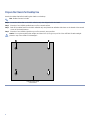
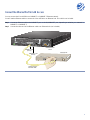
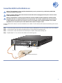
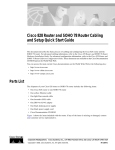
Quick Start Guide
Cisco AS5300 Universal Access Server
1 Documents, Equipment, and Tools
2 Install the Cisco AS5300
3 Gather Configuration Information
4 Configure the Cisco AS5300
5 Obtaining Documentation
6 Obtaining Technical Assistance
1 Documents, Equipment, and Tools
User Documentation
All of the documents described here are available online and on the documentation CD-ROM that you received with your
Cisco AS5300. To be sure of obtaining the latest information, you should access the online documentation.
To print a document in its original page format, access the online document, and click on the PDF icon.
To access online user documentation (PDF and HTML formats):
From Cisco.com at http://www.cisco.com, under Service & Support, select Technical Documents and select Cisco Product
Documentation.
To access user documentation on the Documentation CD-ROM (HTML format only):
On the Documentation CD-ROM, select Cisco Product Documentation.
Paths to specific documents are provided below, starting at Cisco Product Documentation.
Tip To navigate up to the next higher level in the documentation hierarchy, click on CONTENTS in the navigation
bar at the top of each page.
Cisco AS5300 Documentation
Regulatory Compliance and Safety Information
The Regulatory Compliance and Safety Information document provides essential safety information applicable to your router.
This document contains multiple-language translations of the safety warnings applicable to the Cisco AS5300.
You can access this document at: Cisco Product Documentation > Access Servers & Routers > Access Routers > Cisco AS5300
>Regulatory Compliance and Safety Information
Chassis Hardware Installation Guide
The chassis hardware installation guide provides detailed description and installation instructions for the Cisco AS5300 chassis.
You can access this document at: Cisco Product Documentation > Access Servers & Routers > Access Routers > Cisco AS5300
> Hardware Installation Documents for Cisco AS5300 > Cisco AS5300 Chassis Installation Guide
Module Hardware Installation Guide
The module hardware installation guide provides additional detailed description, installation, and cabling information for
Cisco AS5300 modules.
You can access this document at: Cisco Product Documentation > Access Servers & Routers > Access Routers > Cisco AS5300
> Hardware Installation Documents for Cisco AS5300 > Cisco AS5300 Module Installation Guide
Software Configuration Guide
The software configuration guide provides additional detailed configuration information specific to the Cisco AS5300.
You can access this document at: Cisco Product Documentation > Access Servers & Routers > Access Routers > Cisco AS5300
> Configuration Documents for Cisco AS5300 > AS5300 Software Configuration Guide
Voice Over IP Configuration
Voice over IP configuration information provides detailed instructions for configuring VoIP on the Cisco AS5300.
You can access this document at: Cisco Product Documentation > Access Servers & Routers > Access Routers > Cisco AS5300
> Configuration Documents for Cisco AS5300 > VoIP Information
2
Release Notes
Cisco IOS release notes for the Cisco AS5300 provide up-to-date information about specific Cisco IOS software releases used
on Cisco AS5300s.
You can access these documents at: Cisco Product Documentation > Access Servers & Routers > Access Routers> Cisco AS5300
> Cisco IOS Release Notes for AS5300
Hardware Configuration Notes
Cisco AS5300 configuration notes contain various hardware-related instruction procedures, such as:
• Replacing and installing power supplies
• Installing memory modules
• Installing modem modules
• Installing feature cards
• Upgrading VCWare
• Replacing DSPMs
You can access these documents at: Cisco Product Documentation > Access Servers & Routers > Access Routers> Cisco AS5300
> Hardware Installation Documents for Cisco AS5300 > Documentation for Spare Parts
Additional documents of this type are located at: Cisco Product Documentation > Access Servers & Routers > Access Routers>
Cisco AS5300
Cisco IOS Software Documentation
Master Index to Software Documentation (Cisco IOS Releases 12.0 and 12.1)
The master index provides links to topics and commands for specific Cisco IOS software releases.
You can access master indexes at: Cisco Product Documentation > Cisco IOS Software Configuration > Cisco IOS Software
Release you are using > Configuration Guides and Command References > Master Index link for this software release
Configuration Guides
The Cisco IOS software configuration guides provide detailed configuration procedures and examples.
You can access these documents at: Cisco Product Documentation > Cisco IOS Software Configuration > Cisco IOS Software
Release you are using > Configuration Guides and Command References > Configuration guide for your application
Command References
The Cisco IOS software command references provide detailed information about each configuration command.
You can access these documents at: Cisco Product Documentation > Cisco IOS Software Configuration > Cisco IOS Software
Release you are using > Configuration Guides and Command References > Command reference for your application
New Feature Documentation
New Feature Documentation contains detailed information about new features introduced in specific Cisco IOS releases.
You can access these documents at: Cisco Product Documentation > Cisco IOS Software Configuration > Cisco IOS Software
Release you are using > New Feature Documentation
If you have an account on Cisco.com, you can get updated information about platform support for features by accessing Feature
Navigator at the following URL: http://www.cisco.com/go/fn
3
Release Notes
Cisco IOS release notes for all platforms provide up-to-date information about specific Cisco IOS software releases.
You can access these documents at: Cisco Product Documentation > Cisco IOS Software Configuration > Cisco IOS Software
Release you are using > Release Notes
Supporting Documents and Related Documentation
Debug commands and other support documents provide additional information about specific Cisco IOS software releases,
platforms, and applications.
You can access these documents at: Cisco Product Documentation > Cisco IOS Software Configuration > Cisco IOS Software
Release you are using > Supporting Documents or Related Documentation
Additional documents of this type are located at: Cisco Product Documentation > Access Servers & Routers > Access Routers>
Cisco AS5300
Items Included with Cisco AS5300
• Cisco AS5300
• 19- and 24-in. rack-mount brackets
• Rubber feet for desktop installation
• RJ-45-to-DB-9 female DTE adapter (labeled TERMINAL)
• RJ-45-to-DB-25 female DTE adapter (labeled TERMINAL)
• RJ-45-to-DB-25 male DCE adapter (labeled MODEM)
• RJ-45-to-RJ-45 rollover console cable
• ESD–preventive wrist strap
• Carrier removal tool
• Two nylon cable ties
• Two cable tie holders
• Grounding lug
• Power cord
• Quick Start Guide (this document)
• Regulatory Compliance and Safety Information document
• Release Notes for the specific Cisco IOS release installed on the Cisco AS5300
• Documentation CD-ROM and information packet
• Cisco Fast Step CD-ROM
Items Not Included
• Four screws for installing the chassis in a rack
• T1 channel service unit/data service unit (CSU/DSU) or E1 networks terminating unit
• PC (with CD-ROM drive) running terminal emulation software for administrative access
• Modem for remote administrative access
• Ethernet cable (straight-through RJ-45-to-RJ-45)
• 4 T1 cables (straight-through RJ-45-to-RJ-45)
• 4 E1 cables (RJ-45 to E1 network)
4
• Serial 12-in-1 cable (serial to WAN access)
• Slot cover for unused slots
• 19-in. telco rack-mount brackets
2 Install the Cisco AS5300
Warning This unit is intended for installation in restricted access areas. A restricted access area is where access
can only be gained by service personnel through the use of a special tool, lock and key, or other means of security,
and is controlled by the authority responsible for the location.
Prepare the Chassis for Rack-Mounting
You can install the chassis in a rack or on a desktop. For a desktop installation, proceed to the next section, “Prepare the Chassis
for Desktop Use.”
Note Brackets and screws are included for attaching the brackets to the chassis. However, you need four additional
screws to install the chassis in a rack.
Step 1
Attach the brackets using one of the three methods shown below.
Step 2
Install the chassis in a rack.
Front panel forward
Rear panel forward
Rear panel forward,
center-mount telco
5
Prepare the Chassis for Desktop Use
Attach the rubber feet before installing the chassis on a desktop.
Note Rubber feet are included.
Step 1
Locate the rubber feet on the black adhesive strip that shipped with the chassis.
Step 2
Place the Cisco AS5300 upside-down on a flat, smooth surface.
Step 3
Peel off the rubber feet from the black adhesive strip and place them adhesive-side down on the dotted circles at each
corner of the chassis bottom.
Step 4
Place the Cisco AS5300 right-side up on a flat, smooth, secure surface.
Caution Do no place anything that weighs more than 10 lb (4.5 kg) on top of the Cisco AS5300. Excessive weight
placed on top of the chassis could damage it.
Universal access server
chassis bottom
6
Connect the Ethernet Port for LAN Access
You can connect the Cisco AS5300 to a 10BASE-T or 100BASE-T Ethernet network.
You will need an Ethernet cable to connect the Cisco AS5300 to an Ethernet hub. This cable is not included.
Step 1
Connect an Ethernet cable to the 10BASE-T port or the 10/100BASE-T port, depending on whether your network is
10BASE-T or 100BASE-T.
Step 2
Connect the other end of the Ethernet cable to an Ethernet hub (not included).
Universal access
server
10BASE-T port
(RJ-45)
Ethernet hub
100BASE-T port
(RJ-45)
8
7
1
Straight-through
Ethernet cable
7
Connect the T1/PRI Card for WAN Access
Warning Do not work on the system or connect or disconnect cables during periods of lightning activity.
Warning The ISDN connection is regarded as a source of voltage that should be inaccessible to user contact. Do not
attempt to tamper with or open any public telephone operator (PTO)-provided equipment or connection hardware.
Any hardwired connection (other than by a nonremovable, connect-one-time-only plug) must be made only by PTO
staff or suitably trained engineers.
Warning To avoid electric shock, do not connect safety extra-low voltage (SELV) circuits to telephone-network
voltage (TNV) circuits. LAN ports contain SELV circuits, and WAN ports contain TNV circuits. Some LAN and WAN
ports both use RJ-45 connectors. Use caution when connecting cables.
Warning Hazardous network voltages are present in WAN ports regardless of whether power to the router is OFF or
ON. To avoid electric shock, use caution when working near WAN ports. When detaching cables, detach the end
away from the router first.
You can connect the Cisco AS5300 to a T1 or E1/PRI card for WAN access. If you have a E1/PRI card, go to the next procedure.
You need four straight-through RJ-45-to-RJ-45 cables to connect the T1/PRI card to a WAN. These cables are not included.
Note To identify a straight-through cable, hold the connectors side-by-side, with the tab at the back. The wires are
in the same sequence at both ends of the cable.
Step 1
Connect one end of the straight-through RJ-45-to-RJ-45 cable to the T1 port labeled 0 on the rear panel of the
Cisco AS5300.
Step 2
Connect the other end of the cable to the incoming T1 line (RJ-45 jack).
Step 3
Repeats Steps 1 and 2 to connect other cables to the remaining ports.
Straight-through
RJ-45-to-RJ-45 cable
T1/PRI
connectors
(RJ-45)
T1/PRI card
RJ-45 jack
8
Universal access
server
Connect the E1/PRI Card for WAN Access
Warning This equipment is to be installed and maintained by service personnel only as defined by AS/NZS 3260
Clause 1.2.14.3 Service Personnel.
Warning The telecommunications lines must be disconnected 1) before unplugging the main power connector and/or
2) while the housing is open.
Warning The E1 interface card may only be installed in an ACA-permitted customer equipment or a Data Terminal
Equipment (DTE) that is exempted from ACA's permit requirements. The customer equipment must only be housed in
a cabinet that has screw-down lids to stop user access to overvoltages on the customer equipment. The customer
equipment has circuitry that may have telecommunications network voltages on them.
You will need four E1 cables to connect the E1/PRI card to a WAN. The E1 cables and E1 networks terminating units are not
included.
Step 1
Connect the single-connector end of the E1 cable to the port labeled PORT 4 on the rear panel of the Cisco AS5300.
Step 2
Connect the Rx end of the cable to the Receive port of an E1 networks terminating unit.
Step 3
Connect the Tx end of the cable to the Transmit port of the E1 networks terminating unit.
Step 4
Repeats Steps 1 to 3 to connect other cables to the remaining ports.
E1/PRI card
Universal access
server
E1 cable
E1 networks terminating unit
Rx
Tx
9
Connect the Serial Port for WAN Access
Use a serial 12-in-1 cable (DTE if connecting to a DSU or DCE if connecting to a CSU) to connect one of the four synchronous
serial ports on the E1 or T1 PRI cards (with serial support) to a modem or a CSU or DSU. The CSU or DSU provides access to
a WAN.
Step 1
Connect the serial 12-in-1 cable connector on the serial cable to the serial port on the rear panel of the Cisco AS5300.
Step 2
Connect the EIA/TIA-232, EIA/TIA-449, EIA/TIA-530A, EIA-530, V.35, or X.21 connector to the CSU or DSU.
PORT SELECT
LA
A
SA
0
S A
1
SA
2
S
3
A
SA
4
SA
5
S A
6
S
7
15874
RA
LB
T1
T0
T3
T2
ACT OK
RX
TX
Synchronous serial
port (DB-26)
Universal access
server
Serial
transition
cable
Internet
CSU/DSU or
other DCE or DTE
EIA/TIA-232, EIA/TIA-449, EIA/TIA-530A,
EIA-530, V.35 or X.21 connector
10
Connect a Console for Local Administrative Access
To configure the Cisco AS5300 from a locally-connected PC or terminal, you will need an RJ-45-to-RJ-45 rollover cable and a
terminal adapter (RJ-45-to-DB-9 or RJ-45-to-DB-25). The cable and adapter are included.
Step 1
Connect one of the adapters, labeled TERMINAL, to the communications port (usually labeled COM) on your PC or
terminal. (This communications port is also known as a console port.)
Step 2
Connect one end of the RJ-45-to-RJ-45 rollover cable to the adapter.
Step 3
Connect the other end of the RJ-45-to-RJ-45 rollover cable to the port labeled CONSOLE on the rear panel of the
Cisco AS5300.
Step 4
Configure your PC terminal emulation software or terminal for 9600 baud, 8 data bits, no parity, and 1 stop bit.
Universal access
server
Console port
(RJ-45)
(labeled CONSOLE)
RJ-45-to-RJ-45
rollover cable
PC (laptop)
RJ-45-to-DB-9 or
RJ-45-to-DB-25 adapter
(labeled TERMINAL)
11
Connect a Modem for Remote Administrative Access (Optional)
To configure the Cisco AS5300 from a remote location, you will need an RJ-45-to-RJ-45 rollover cable and a modem adapter
(RJ-45-to-DB-25) for connecting a modem.
If you will not be using a modem to configure the Cisco AS5300 remotely, skip this procedure and go to Connect Power, page 13.
Note The cable and adapter are included. The modem is not included.
Step 1
Connect the adapter labeled MODEM to your modem.
Step 2
Connect the RJ-45-to-RJ-45 rollover cable to the adapter.
Step 3
Connect the other end of the RJ-45-to-RJ-45 rollover cable to the port labeled AUX on the rear panel of the
Cisco AS5300.
Auxiliary port
(RJ-45)
(labeled AUX)
Universal access
server
RJ-45-to-RJ-45
rollover cable
Modem
RJ-45-to-DB-25 adapter
(labeled MODEM)
12
Connect Power
The access server is available with either an AC or DC power supply. You can also order a power supply as a spare if you decide
later that you need a different type of power supply or the power supply fails.
Warning Do not touch the power supply when the power cord is connected. For systems with a power switch, line
voltages are present within the power supply even when the power switch is off and the power cord is connected.
For systems without a power switch, line voltages are present within the power supply when the power cord is
connected.
Connecting the AC Power Cord
Take these steps:
Step 1
Connect one end of the power cord to the power connector on the rear panel of the access server.
Step 2
Connect the other end of the power cord to the power outlet.
Warning The plug-socket combination must be accessible at all times because it serves as the main disconnecting
device.
Universal access
server
To power
outlet
Power
switch
Wiring the DC Power Supply
If you ordered the access server with a DC power supply, follow the procedure in this section to wire the terminal block.
Warning A readily accessible two-poled disconnect device must be incorporated in the fixed wiring.
Warning Before performing any of the following procedures, ensure that power is removed from the DC circuit. To
ensure that all power is OFF, locate the circuit breaker on the panel board that services the DC circuit, switch the
circuit breaker to the OFF position, and tape the switch handle of the circuit breaker in the OFF position.
Note This product is intended for installation in restricted access areas and is approved for connection using 12 or
14 AWG copper conductors only. The installation must comply with all applicable codes.
Refer to the figure and follow these steps to wire the terminal block:
Step 1
Note the orientation of the DC power supply. The power supply cord should have three wires: +48 VDC, -48 VDC,
and a safety ground (green wire).
Note For central office installations, it is recommended to use a 6 AWG green ground wire with one end connected
to reliable earth. The other end of the wire should be crimped onto the double-hole lug provided in the installation
pack. The lug should be secured to the mating holes on either side of the chassis with the two screws included in the
accessory pack.
13
Warning The illustration shows the DC power supply terminal block. Wire the DC power supply using the appropriate
wire terminations at the wiring end, as illustrated. The proper wiring sequence is ground to ground, positive to
positive, and negative to negative. Note that the ground wire should always be connected first and disconnected last.
Caution In a DC power supply installation do not connect the -48 VDC return to chassis ground at the Cisco AS5300.
A single-point ground is recommended at the power distribution rack.
Step 2
Strip off a quarter of an inch (1/4 in. [0.625 cm]) of insulation on the safety ground, +48 VDC, and -48 VDC input
wires.
Step 3
Install the safety ground (green wire) into the terminal block ground connector and tighten the locking screw. Ensure
that no bare wire is exposed.
Caution Do not overtorque the terminal block contact screws. The recommended torque is 8.2 ± 0.4 inch-lb.
Step 4
Insert the +48 VDC wire into the terminal block positive connector (+) and tighten the locking screw. Ensure that no
bare wire is exposed.
Step 5
Insert the -48 VDC wire into the terminal block negative connector (-) and tighten the locking screw. Ensure that no
bare wire is exposed.
Step 6
Secure the power supply cord to the cable strain-relief clamps on the DC power supply with cable ties.
Warning After wiring the DC power supply, remove the tape from the circuit breaker switch handle and reinstate
power by moving the handle of the circuit breaker to the ON position.
Mounting screw
Mounting screw
Terminal
block
H10720
On/off
switch
Mounting screw
Strain-relief
clamp
Power Up the Cisco AS5300
Power up the access server. The internal power supply fan should power on. Messages will begin to appear on your console
screen.
Caution After you start the Cisco AS5300, it might take several minutes for the startup messages to stop. Do not
press any keys until you see the following message:
Would you like to enter the initial configuration dialog? [yes]:
While you are waiting for this message to appear, proceed to Section 3 Gather Configuration Information.
14
3 Gather Configuration Information
Use this section to help gather and organize the information you need to run the setup script to configure your Cisco AS5300.
The information in the table is not an exhaustive list, but provided only as a starting point when using the setup script.
Note If you do not have this information, you can get it from your network administrator.
Item
Ask Your Network Administrator
1.
What do you want to name the Cisco AS5300 (to
distinguish it from other Cisco devices on your
network)?
2.
What do you want the encrypted enable secret
password to be? (Note: This password cannot be
Enter the Information in This Column
seen when viewing the configuration and
therefore is more secure.)
3.
What do you want the nonencrypted enable
password to be? (This password can be seen when
viewing the configuration and therefore is less
secure.)
4.
What do you want the password for remote console
access to be? This is referred to as the virtual
terminal password.
5.
Do you want to configure the Cisco AS5300 for:
SNMP? If so,
• What is the public (read-only) community
string?
• What is the private (read-write) community
string?
LAT?
AppleTalk?
• AppleTalk multizone networks?
• What are the AppleTalk zone names?
• What are the AppleTalk network numbers?
DECNet?
IP?
IGRP routing?
• What is the IGRP autonomous system number?
CLNS?
IPX?
• What are the IPX network numbers?
VINES?
XNS?
Apollo?
Bridging?
15
Item
Ask Your Network Administrator
6.
Do you want to configure the modems for:
Default chat script?
Dial-in IP SLIP/PPP access?
Dynamic IP address?
Default IP address?
TCP header compression?
Routing updates on async lines?
Async IPX?
ARA?
• ARA clients?
• Zone name for ARA clients?
7.
Will you be using the Ethernet 0 (10BASE-T)
interface?
What is the IP address?
How many bits in the subnet mask?
Configure AppleTalk on this interface?
Extended AppleTalk network?
— AppleTalk network number
— AppleTalk zone name?
Configure IPX on this interface?
— IPX network number?
8.
Will you be using the Fast Ethernet 0 (100BASE-T)
interface?
What is the IP address?
How many bits in the subnet mask?
Configure AppleTalk on this interface?
Extended AppleTalk network?
• AppleTalk network number
• AppleTalk zone name?
Configure IPX on this interface?
• IPX network number?
9.
Will you be using the backhaul serial interface for
WAN access?
What is the IP address?
How many bits in the subnet mask?
Configure AppleTalk on this interface?
Extended AppleTalk network?
• AppleTalk network number
• AppleTalk zone name?
Configure IPX on this interface?
• IPX network number?
16
Enter the Information in This Column
4 Configure the Cisco AS5300
Use any of the following options for configuring your Cisco AS5300:
• Cisco Fast Step Software
• Cisco IOS Release Setup Script
• Initial Configuration Using the CLI (Manual Configuration)
• Configuring VoIP
The option you select depends on how you want to configure your Cisco AS5300. Use the following information to help you
decide which option to select.
Using Cisco Fast Step Software
Cisco Fast Step is a setup utility with a graphical user interface. It provides easy, step-by-step instructions for setting up some
of the most commonly used options available on the Cisco AS5300. Use Cisco Fast Step to configure your Cisco AS5300 with
the following options:
• Protocols and services (IP, IPX, and NetBEUI)
• LAN or WAN topology of 10BASE-T, 10/100BASE-T, and serial ports
• Controller settings (PRI or channelized T1/E1 interfaces)
• WAN encapsulation settings (Frame Relay and HDLC)
• LAN or WAN side IP or IPX settings
• Dial-in side IP or IPX settings
• IP address pools or DHCP server settings for dial-in users
• Cisco AS5300 security and security server settings
• Routing protocol settings including default and user-defined (static) routes
For all other configurations, use the Cisco IOS release setup script (see the section, “Cisco IOS Release Setup Script,” later in
this section) or refer to the Cisco AS5300 Universal Access Server Software Configuration Guide for detailed instructions on
using the command-line interface to configure your Cisco AS5300.
Cisco Fast Step Software
Install and Run Cisco Fast Step
Step 1
Insert the Cisco Fast Step CD-ROM into the CD-ROM drive of the local PC you connected in the “Connect a Console
for Local Administrative Access” section.
Step 2
The Fast Step install program starts Setup.exe automatically. If it does not, use the following steps to start the Fast Step
program:
Step 3
Double-click the My Computer icon on your computer desktop.
Step 4
Double-click the CD icon.
Step 5
Double-click the Setup.exe icon.
The install program prompts you for the information it needs to install Cisco Fast Step, then copies the software to
your hard drive.
17
Configure the Cisco AS5300
After installation, the Cisco Fast Step setup program starts automatically. Follow the onscreen instructions to guide you through
configuring and testing the Cisco AS5300.
Cisco IOS Release Setup Script
Timesaver Section 3, “Gather Configuration Information,” is provided to help you gather the appropriate
information before you begin to configure the Cisco AS5300 using the setup script.
This section shows how to start the Cisco IOS release setup script in the system configuration dialog to complete a basic
configuration for the Cisco AS5300. For detailed steps for the setup script, refer to the Cisco AS5300 Universal Access Server
Software Configuration Guide.
Note If you make a mistake, you can exit and run the system configuration dialog again. Press Ctrl-c, and type setup
at the enable mode prompt (5300#).
Step 1
Power ON the Cisco AS5300. The power switch is on the rear panel of the Cisco AS5300, at the lower right corner,
near the power cord. Messages will begin to appear in your terminal emulation program window.
Caution Do not press any keys on the keyboard until the messages stop. Any keys pressed during this time are
interpreted as the first command typed when the messages stop, which might cause the Cisco AS5300 to power off
and start over. It will take a few minutes for the messages to stop.
The messages look similar to the following:
Note The messages vary, depending on the Cisco IOS software release and feature set you selected. The screen
displays in this section are for reference only and might not exactly reflect the messages on your screen.
System Bootstrap, Version 12.0(3)T, RELEASED SOFTWARE
Copyright (c) 1994-1999 by Cisco Systems, Inc.
AS5300 processor with 32768 Kbytes of main memory
rommon 3 > b flash:2:
program load complete, entry point:0x80008000, size:0x4e3b38
Self decompressing the image :
########################################################################################]
Restricted Rights Legend
Use, duplication, or disclosure by the Government is
subject to restrictions as set forth in subparagraph
(c) of the Commercial Computer Software - Restricted
Rights clause at FAR sec. 52.227-19 and subparagraph
(c) (1) (ii) of the Rights in Technical Data and Computer
Software clause at DFARS sec. 252.227-7013.
Cisco Systems, Inc.
170 West Tasman Drive
San Jose, California 95134-1706
Cisco Internetwork Operating System Software
Cisco Internetwork Operating System Software
IOS (tm) 5300 Software (C5300-IS-M), Version 12.2(2)XA, EARLY DEPLOYMENT RELEASE
SOFTWARE (fc1)
TAC:Home:SW:IOS:Specials for info
Copyright (c) 1986-2001 by cisco Systems, Inc.
Compiled Tue 26-Jun-01 23:47 by hwcheng
Image text-base: 0x600089C8, data-base: 0x61000000
IOS (tm) 5300 Software (C5300-IS-M), Released Version 12.0(19981001:221340)
Copyright (c) 1986-1999 by cisco Systems, Inc.
18
--- System Configuration Dialog ---
Step 2
When the following prompt appears, enter yes to continue:
Would you like to enter the initial configuration dialog? [yes]: yes
At any point you may enter a question mark '?' for help.
Use ctrl-c to abort configuration dialog at any prompt.
Default settings are in square brackets '[]'.
When you are done selecting options and saving the script, the Cisco AS5300 displays the 5300> prompt, which
indicates that you are at the command-line interface (CLI) and you have just completed the basic Cisco AS5300
configuration. However, this is not a complete configuration. At this point you have two options:
• Run the setup script again and create another configuration by entering the following commands:
5300> enable
Password: password
5300# setup
• Modify the existing configuration or configure additional features with the CLI as described in the Cisco AS5300
Universal Access Server Software Configuration Guide.
Initial Configuration Using the CLI (Manual Configuration)
This section shows how to bring up a command line interface (CLI) prompt for configuration using the CLI, and it directs you to
the documentation for CLI configuration.
Step 1
To proceed with manual configuration using the CLI, enter no.
Would you like to enter the initial configuration dialog? [yes/no]: no
Step 2
Press Return to terminate autoinstall and continue with manual configuration.
Would you like to terminate autoinstall? [yes] Return
Several messages are displayed, ending with a line similar to the following:
...
Copyright (c) 1986-2000 by cisco Systems, Inc.
Compiled <date> <time> by <person>
Step 3
Press Return to bring up the Router> prompt.
...
flashfs[4]: Initialization complete.
Router>
Step 4
Enter privileged EXEC mode.
Router> enable
Router#
The router is now ready for configuration using the CLI.
For configuration using the CLI, refer to the applicable configuration procedures in the Cisco AS5300 Universal Access Server
Software Configuration Guide.
You can access this document at: Cisco Product Documentation > Access Servers & Routers > Access Routers > Cisco AS5300
> Configuration Documents for Cisco AS5300 > AS5300 Software Configuration Guide
19
Configuring VoIP
The actual configuration procedure depends entirely upon the topology of your voice network, but, in general, you need to
complete the following configuration tasks:
1. Configure IP Networks for Real-Time Voice Traffic.
2. Configuring Voice Ports for ISDN PRI.
3. Configuring the D Channels.
4. Configuring the Dial Peers.
5. Configuring Voice Network Data.
For detailed procedures, see the Cisco AS5300 Universal Access Server Software Configuration Guide. You can access this
document at: Cisco Product Documentation > Access Servers & Routers > Access Routers > Cisco AS5300 > Configuration
Documents for Cisco AS5300 > AS5300 Software Configuration Guide
For detailed examples of command output, see the Voice Over IP for the Cisco AS5300 Configuration Guide. You can access
this document at: Cisco Product Documentation > Access Servers & Routers > Access Routers > Cisco AS5300 > Configuration
Documents for Cisco AS5300 > VoIP Information > Voice over IP for the Cisco AS5300
For additional voice configuration see the Cisco IOS Voice, Video, and Fax Configuration Guide. You can access this
documentatio at: Cisco Product Documentation > Cisco IOS Software Configuration > Cisco IOS Software Release you are
using > Configuration Guides and Command References > Cisco IOS Voice, Video, and Fax Configuration Guide
Where to Go Next
For additional specialized configuration procedures, refer to the appropriate Cisco IOS software configuration documentation,
available on the Documentation CD-ROM and on Cisco.com:
Tip See the “User Documentation” section on page 2 for help in locating these documents.
For detailed configuration information specific to the Cisco AS5300:
Cisco AS5300 Universal Access Server Software Configuration Guide.
You can access this document at: Cisco Product Documentation > Access Servers & Routers > Access Routers > Cisco
AS5300 > Configuration Documents for Cisco AS5300 > AS5300 Software Configuration Guide
For detailed configuration information for specific features:
Configuration Guides and Command References for the Cisco IOS software release installed on your Cisco router.
You can access these documents at: Cisco Product Documentation > Cisco IOS Software Configuration
> Cisco IOS Software Release you are using > Configuration Guides and Command References
For new features associated with a specific software release:
New feature documentation for the Cisco IOS software release installed on your Cisco router.
You can access these documents at: Cisco Product Documentation > Cisco IOS Software Configuration
> Cisco IOS Software Release you are using > New Feature Documentation
Feature Navigator
If you have an account on Cisco.com, you can get updated information about platform support for features by accessing
Feature Navigator at the following URL:
http://www.cisco.com/go/fn
20
5 Obtaining Documentation
The following sections provide sources for obtaining documentation from Cisco Systems.
World Wide Web
You can access the most current Cisco documentation on the World Wide Web at the following sites:
• http://www.cisco.com
• http://www-china.cisco.com
• http://www-europe.cisco.com
Documentation CD-ROM
Cisco documentation and additional literature are available in a CD-ROM package, which ships with your product. The
Documentation CD-ROM is updated monthly and may be more current than printed documentation. The CD-ROM package
is available as a single unit or as an annual subscription.
Ordering Documentation
Cisco documentation is available in the following ways:
• Registered Cisco Direct Customers can order Cisco Product documentation from the Networking Products MarketPlace:
http://www.cisco.com/cgi-bin/order/order_root.pl
• Registered Cisco.com users can order the Documentation CD-ROM through the online Subscription Store:
http://www.cisco.com/go/subscription
• Nonregistered Cisco.com users can order documentation through a local account representative by calling Cisco corporate
headquarters (California, USA) at 408 526-7208 or, in North America, by calling 800 553-NETS(6387).
Documentation Feedback
If you are reading Cisco product documentation on the World Wide Web, you can submit technical comments electronically.
Click Feedback in the toolbar and select Documentation. After you complete the form, click Submit to send it to Cisco.
You can e-mail your comments to [email protected].
To submit your comments by mail, for your convenience many documents contain a response card behind the front cover.
Otherwise, you can mail your comments to the following address:
Cisco Systems, Inc.
Document Resource Connection
170 West Tasman Drive
San Jose, CA 95134-9883
We appreciate your comments.
21
6 Obtaining Technical Assistance
Cisco provides Cisco.com as a starting point for all technical assistance. Customers and partners can obtain documentation,
troubleshooting tips, and sample configurations from online tools. For Cisco.com registered users, additional troubleshooting
tools are available from the TAC website.
Cisco.com
Cisco.com is the foundation of a suite of interactive, networked services that provides immediate, open access to Cisco
information and resources at anytime, from anywhere in the world. This highly integrated Internet application is a powerful,
easy-to-use tool for doing business with Cisco.
Cisco.com provides a broad range of features and services to help customers and partners streamline business processes and
improve productivity. Through Cisco.com, you can find information about Cisco and our networking solutions, services, and
programs. In addition, you can resolve technical issues with online technical support, download and test software packages,
and order Cisco learning materials and merchandise. Valuable online skill assessment, training, and certification programs are
also available.
Customers and partners can self-register on Cisco.com to obtain additional personalized information and services. Registered
users can order products, check on the status of an order, access technical support, and view benefits specific to their
relationships with Cisco.
To access Cisco.com, go to the following website:
http://www.cisco.com
Technical Assistance Center
The Cisco TAC website is available to all customers who need technical assistance with a Cisco product or technology that is
under warranty or covered by a maintenance contract.
Contacting TAC by Using the Cisco TAC Website
If you have a priority level 3 (P3) or priority level 4 (P4) problem, contact TAC by going to the TAC website:
http://www.cisco.com/tac
P3 and P4 level problems are defined as follows:
• P3—Your network performance is degraded. Network functionality is noticeably impaired, but most business operations
continue.
• P4—You need information or assistance on Cisco product capabilities, product installation, or basic product configuration.
In each of the above cases, use the Cisco TAC website to quickly find answers to your questions.
To register for Cisco.com, go to the following website:
http://www.cisco.com/register/
If you cannot resolve your technical issue by using the TAC online resources, Cisco.com registered users can open a case online
by using the TAC Case Open tool at the following website:
http://www.cisco.com/tac/caseopen
22
Contacting TAC by Telephone
If you have a priority level 1 (P1) or priority level 2 (P2) problem, contact TAC by telephone and immediately open a case. To
obtain a directory of toll-free numbers for your country, go to the following website:
http://www.cisco.com/warp/public/687/Directory/DirTAC.shtml
P1 and P2 level problems are defined as follows:
• P1—Your production network is down, causing a critical impact to business operations if service is not restored quickly.
No workaround is available.
• P2—Your production network is severely degraded, affecting significant aspects of your business operations. No
workaround is available.
23
Corporate Headquarters
Cisco Systems, Inc.
170 West Tasman Drive
San Jose, CA 95134-1706
USA
www.cisco.com
Tel: 408 526-4000
800 553-NETS (6387)
Fax: 408 526-4100
European Headquarters
Cisco Systems Europe
11 Rue Camille Desmoulins
92782 Issy-les-Moulineaux
Cedex 9
France
www-europe.cisco.com
Tel: 33 1 58 04 60 00
Fax: 33 1 58 04 61 00
Americas Headquarters
Cisco Systems, Inc.
170 West Tasman Drive
San Jose, CA 95134-1706
USA
www.cisco.com
Tel: 408 526-7660
Fax: 408 527-0883
Asia Pacific Headquarters
Cisco Systems Australia, Pty., Ltd
Level 9, 80 Pacific Highway
P.O. Box 469
North Sydney
NSW 2060 Australia
www.cisco.com
Tel: +61 2 8448 7100
Fax: +61 2 9957 4350
Cisco Systems has more than 200 offices in the following countries. Addresses, phone numbers, and fax numbers are listed on the
Cisco Web site at www.cisco.com/go/offices
Argentina • Australia • Austria • Belgium • Brazil • Bulgaria • Canada • Chile • China PRC • Colombia • Costa Rica • Croatia • Czech Republic • Denmark • Dubai, UAE
Finland • France • Germany • Greece • Hong Kong SAR • Hungary • India • Indonesia • Ireland • Israel • Italy • Japan • Korea • Luxembourg • Malaysia • Mexico
The Netherlands • New Zealand • Norway • Peru • Philippines • Poland • Portugal • Puerto Rico • Romania • Russia • Saudi Arabia • Scotland • Singapore • Slovakia
Slovenia • South Africa • Spain • Sweden • Switzerland • Taiwan • Thailand • Turkey • Ukraine • United Kingdom • United States • Venezuela • Vietnam • Zimbabwe
Copyright © 1998, 1999, 2001 Cisco Systems, Inc. All rights reserved. AccessPath, AtmDirector, Browse with Me, CCIP, CCSI, CD-PAC, CiscoLink, the Cisco Powered Network logo, Cisco Systems Networking
Academy, the Cisco Systems Networking Academy logo, Fast Step, Follow Me Browsing, FormShare, FrameShare, GigaStack, IGX, Internet Quotient, IP/VC, iQ Breakthrough, iQ Expertise, iQ FastTrack, iQ
Net Readiness Scorecard, the iQ logo, MGX, the Networkers logo, Packet, RateMUX, ScriptBuilder, ScriptShare, SlideCast, SMARTnet, TransPath, Unity, Voice LAN, Wavelength Router, and WebViewer, are
trademarks of Cisco Systems, Inc.; Changing the Way We Work, Live, Play, and Learn, Discover All That’s Possible, and Empowering the Internet Generation, are service marks of Cisco Systems, Inc.; and
Aironet, ASIST, BPX, Catalyst, CCDA, CCDP, CCIE, CCNA, CCNP, Cisco, the Cisco Certified Internetwork Expert Logo, Cisco IOS, the Cisco IOS logo, Cisco Press, Cisco Systems, Cisco Systems Capital,
the Cisco Systems logo, Enterprise/Solver, EtherChannel, EtherSwitch, FastHub, FastSwitch, IOS, IP/TV, LightStream, MICA, Network Registrar, PIX, Post-Routing, Pre-Routing, Registrar, StrataView Plus,
Stratm, SwitchProbe, TeleRouter, and VCO are registered trademarks of Cisco Systems, Inc. and/or its affiliates in the U.S. and certain other countries.
All other trademarks mentioned in this document or Web site are the property of their respective owners. The use of the word partner does not imply a partnership relationship between Cisco and any other
company. (0108R)
78-4531-06