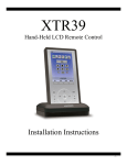
1
Sun StorageTek™ 6140 Array
Release Notes
Release 6.2
Sun Microsystems, Inc.
www.sun.com
Part No. 820-6710-10
November 2008, Revision A
Submit comments about this document at: http://www.sun.com/hwdocs/feedback
Copyright 2007 Sun Microsystems, Inc., 4150 Network Circle, Santa Clara, California 95054, U.S.A. All rights reserved.
Sun Microsystems, Inc. has intellectual property rights relating to technology that is described in this document. In particular, and without
limitation, these intellectual property rights may include one or more of the U.S. patents listed at http://www.sun.com/patents and one or
more additional patents or pending patent applications in the U.S. and in other countries.
This document and the product to which it pertains are distributed under licenses restricting their use, copying, distribution, and
decompilation. No part of the product or of this document may be reproduced in any form by any means without prior written authorization of
Sun and its licensors, if any.
Third-party software, including font technology, is copyrighted and licensed from Sun suppliers.
Parts of the product may be derived from Berkeley BSD systems, licensed from the University of California. UNIX is a registered trademark in
the U.S. and in other countries, exclusively licensed through X/Open Company, Ltd.
Sun, Sun Microsystems, the Sun logo, AnswerBook2, docs.sun.com, Sun StorEdge, Solaris, Java, Sun StorageTek, and Solstice DiskSuite are
trademarks or registered trademarks of Sun Microsystems, Inc., or its subsidiaries, in the U.S. and in other countries.
All SPARC trademarks are used under license and are trademarks or registered trademarks of SPARC International, Inc. in the U.S. and in other
countries. Products bearing SPARC trademarks are based upon an architecture developed by Sun Microsystems, Inc.
Legato Networker is a registered trademark of Legato Systems Inc.
Netscape Navigator and Mozilla are trademarks or registered trademarks of Netscape Communications Corporation in the United States and
other countries.
The OPEN LOOK and Sun™ Graphical User Interface was developed by Sun Microsystems, Inc. for its users and licensees. Sun acknowledges
the pioneering efforts of Xerox in researching and developing the concept of visual or graphical user interfaces for the computer industry. Sun
holds a non-exclusive license from Xerox to the Xerox Graphical User Interface, which license also covers Sun’s licensees who implement OPEN
LOOK GUIs and otherwise comply with Sun’s written license agreements.
U.S. Government Rights—Commercial use. Government users are subject to the Sun Microsystems, Inc. standard license agreement and
applicable provisions of the FAR and its supplements.
DOCUMENTATION IS PROVIDED "AS IS" AND ALL EXPRESS OR IMPLIED CONDITIONS, REPRESENTATIONS AND WARRANTIES,
INCLUDING ANY IMPLIED WARRANTY OF MERCHANTABILITY, FITNESS FOR A PARTICULAR PURPOSE OR NON-INFRINGEMENT,
ARE DISCLAIMED, EXCEPT TO THE EXTENT THAT SUCH DISCLAIMERS ARE HELD TO BE LEGALLY INVALID.
Copyright 2007 Sun Microsystems, Inc., 4150 Network Circle, Santa Clara, Californie 95054, Etats-Unis. Tous droits réservés.
Sun Microsystems, Inc. a les droits de propriété intellectuels relatants à la technologie qui est décrit dans ce document. En particulier, et sans la
limitation, ces droits de propriété intellectuels peuvent inclure un ou plus des brevets américains énumérés à http://www.sun.com/patents et
un ou les brevets plus supplémentaires ou les applications de brevet en attente dans les Etats-Unis et dans les autres pays.
Ce produit ou document est protégé par un copyright et distribué avec des licences qui en restreignent l’utilisation, la copie, la distribution, et la
décompilation. Aucune partie de ce produit ou document ne peut être reproduite sous aucune forme, par quelque moyen que ce soit, sans
l’autorisation préalable et écrite de Sun et de ses bailleurs de licence, s’il y en a.
Le logiciel détenu par des tiers, et qui comprend la technologie relative aux polices de caractères, est protégé par un copyright et licencié par des
fournisseurs de Sun.
Des parties de ce produit pourront être dérivées des systèmes Berkeley BSD licenciés par l’Université de Californie. UNIX est une marque
déposée aux Etats-Unis et dans d’autres pays et licenciée exclusivement par X/Open Company, Ltd.
Sun, Sun Microsystems, le logo Sun, AnswerBook2, docs.sun.com, Sun StorEdge, Solaris, Java, Sun StorageTek, et Solstice DiskSuite sont des
marques de fabrique ou des marques déposées de Sun Microsystems, Inc., ou ses filiales, aux Etats-Unis et dans d’autres pays.
Netscape Navigator et Mozilla est une marques de Netscape Communications Corporation aux Etats-Unis et dans d’autres pays.
Toutes les marques SPARC sont utilisées sous licence et sont des marques de fabrique ou des marques déposées de SPARC International, Inc.
aux Etats-Unis et dans d’autres pays. Les produits portant les marques SPARC sont basés sur une architecture développée par Sun
Microsystems, Inc.
L’interface d’utilisation graphique OPEN LOOK et Sun™ a été développée par Sun Microsystems, Inc. pour ses utilisateurs et licenciés. Sun
reconnaît les efforts de pionniers de Xerox pour la recherche et le développement du concept des interfaces d’utilisation visuelle ou graphique
pour l’industrie de l’informatique. Sun détient une license non exclusive de Xerox sur l’interface d’utilisation graphique Xerox, cette licence
couvrant également les licenciées de Sun qui mettent en place l’interface d ’utilisation graphique OPEN LOOK et qui en outre se conforment
aux licences écrites de Sun.
LA DOCUMENTATION EST FOURNIE "EN L’ÉTAT" ET TOUTES AUTRES CONDITIONS, DECLARATIONS ET GARANTIES EXPRESSES
OU TACITES SONT FORMELLEMENT EXCLUES, DANS LA MESURE AUTORISEE PAR LA LOI APPLICABLE, Y COMPRIS NOTAMMENT
TOUTE GARANTIE IMPLICITE RELATIVE A LA QUALITE MARCHANDE, A L’APTITUDE A UNE UTILISATION PARTICULIERE OU A
L’ABSENCE DE CONTREFAÇON.
Contents
1.
Sun StorageTek 6140 Array Release Notes, Release 6.2
Features in This Release
2
Sun StorageTek 6140 Array Features
6140 Array Ship Kit Contents
Management Software
2
3
4
Array Expansion Module Support
4
Licenses For Optional Premium Features
System Requirements
4
5
Disk Drives and Tray Capacity
Data Host Requirements
6
6
Multipathing Software
7
Supported Enterprise Software
19
Supported FC and Multilayer Switches
Installing Firmware
20
20
Upgrading Array Firmware
▼
1
20
To Upgrade the Firmware on the Array
Updating the SSD Driver for the Solaris OS
21
22
▼
To Update the SSD Driver for the Solaris 8 OS
22
▼
To Update the SSD Driver for the Solaris 9 OS
22
iii
Known Issues
23
Installation and Initial Configuration Issues
Hardware and Firmware Issues
Documentation Issues
25
26
Operational Information
Release Documentation
23
28
31
Service Contact Information
Third-Party Web Sites
33
A.
Disk Drive Insertion
35
B.
Using DC Power
32
39
DC Power Overview
39
Site Preparation for DC Power
Site Wiring and Power
DC Power Input
41
41
42
DC Power Connector Cables and Source Wires
Additional DC Specifications
Installation Notes for DC Power
Ship Kit Changes
DC Power LEDS
43
43
44
44
DC Power Caution When Link Rate Switching
Connecting Power Cables
▼
Connecting the Cables
44
45
45
Turning Off the DC Power During an Emergency
Relocation Cautions
C.
46
Preparing the Two-Post Telco Rack
Preparing the Telco Rack
49
50
Attaching the Rails to a Telco 2-Post Rack
iv
43
Sun StorageTek 6140 Array Release Notes • November 2008
50
46
Installing a Tray in a Telco 2-Post Rack
55
Contents
v
vi
Sun StorageTek 6140 Array Release Notes • November 2008
Tables
TABLE 1
Comparison of 2GB Cache and 4GB Cache Array Configurations
TABLE 2
Supported Expansion Modules - 6000 Series Arrays
TABLE 3
Available Licenses for Premium Features,
TABLE 4
Supported Disk Drives
TABLE 5
6540 Multipathing Software
TABLE 6
Supported Solaris Data Host Platforms
TABLE 7
Supported Microsoft Windows Data Host Platforms
TABLE 8
Supported Linux Data Host Platforms
14
TABLE 9
Other Supported Data Host Platforms
17
TABLE 10
Supported Enterprise Software
TABLE 1
6540Firmware Upgrades
TABLE B-1
Lights on the Array Module
2
4
5
6
7
9
10
19
21
44
vii
viii
Sun StorageTek 6140 Array Release Notes • November 2008
Sun StorageTek 6140 Array
Release Notes, Release 6.2
This document contains important release information about the Sun StorageTek™
6140 Array or information that was not available at the time the product
documentation was published. Read this document so that you are aware of issues
or requirements that can affect the installation and operation of the Sun StorageTek
6140 Array.
These Release Notes cover the array and related hardware issues. For information
about the management software for the array, see the latest Common Array Manager
Software Release Notes. The CAM release is currently version 6.2.0 and the latest
firmware version is 07.15.11.11.
Make sure you look for the latest patches pertaining to your environment. Select
Patches & Updates from the following site:
http://www.sun.com/download/
The Release Notes consist of the following sections:
■
“Features in This Release” on page 2
■
“System Requirements” on page 5
■
“Installing Firmware” on page 20
■
“Known Issues” on page 23
■
“Operational Information” on page 28
■
“Release Documentation” on page 31
■
“Service Contact Information” on page 32
■
“Third-Party Web Sites” on page 33
1
Features in This Release
This section describes the main features of the Sun StorageTek 6140 Array, including
the following:
■
“Sun StorageTek 6140 Array Features” on page 2
■
“6140 Array Ship Kit Contents” on page 3
■
“Management Software” on page 4
■
“Array Expansion Module Support” on page 4
■
“Licenses For Optional Premium Features” on page 4
Sun StorageTek 6140 Array Features
The Sun StorageTek 6140 Array is a 4-Gb/2-Gb Fibre Channel (FC) array that offers
both direct attached and SAN attached storage. The Sun StorageTek 6140 Array
features:
■
Eight or four SFP host ports (four or two per controller)
■
1-Gb, 2-Gb, and 4-Gb host interface speed
■
Dual redundant controllers
■
FC and/or Serial Advanced Technology Attachment (SATA)-2 disk drives
■
Support of up to 6 expansion trays with one controller tray for the 4-Gb model or
up to three expansion trays with one controller tray for the 2-Gb model
■
Switched drive tray (contains an FC switch)
■
112 maximum drives (7 trays with up to 16 drives each) for the 4-Gb array
■
AC or DC Power
The Sun StorageTek 6140 Array is available in a 2 GByte cache and a 4 GByte cache
configuration. TABLE 1 compares the 2 GB cache and 4GB cache array configurations.
TABLE 1
2
Comparison of 2GB Cache and 4GB Cache Array Configurations
Sun StorageTek 6140
Array with 2GB Cache
Sun StorageTek 6140
Array with 4GB Cache
Total cache size per array
2GB
4GB
Number of host ports (4Gb/s) per
array
4
8
Maximum number of drives
supported
64
112
Sun StorageTek 6140 Array Release Notes • November 2008
TABLE 1
Comparison of 2GB Cache and 4GB Cache Array Configurations
Sun StorageTek 6140
Array with 2GB Cache
Sun StorageTek 6140
Array with 4GB Cache
Maximum array configuration
1x4
1x7
Maximum RAW capacity
32TBytes
56TBytes
Optional storage domains
supported
4/8/16
4/8/16/64
6140 Array Ship Kit Contents
The Sun StorageTek 6140 Array controller and expansion trays are shipped
separately. The following is a list of the contents in the tray ship kits.
■
■
Ship kit for the controller tray:
■
Two 5-meter Fibre Channel (FC) cables for connecting the redundant array of
independent disks (RAID) controllers to your storage area network (SAN) or
host
■
Two 6-meter RJ45 -RJ45 Ethernet cables
■
Two RJ45-miniDIN cables
■
One RJ45-DB9 adapter
■
One RJ45-DB9 adapter with null modem
■
Sun StorageTek Common Array Manager Software CD
■
Sun StorageTek Common Array Manager Software Installation Guide
■
Sun StorageTek 6140 Array Hardware Installation Guide
■
Sun StorageTek 6140 Array Poster
■
Accessing Documentation card
Ship kit for each expansion tray:
■
Two 2-meter optical FC cables and SFPs
■
Accessing Documentation guide
AC power cords (or the optional DC power option) are shipped separately with each
tray.
Sun StorageTek 6140 Array Release Notes, Release 6.2
3
Management Software
The Sun StorageTek Common Array Manager software provides you with an easyto-use interface to configure, manage, and monitor Sun StorageTek storage systems,
including the Sun StorageTek 6140 Array. You can also use the Common Array
Manager software to diagnose problems, view events, and monitor the health of
your array.
The Common Array Manager is described separately in the Sun StorageTek
Common Array Manager documentation.
Array Expansion Module Support
Controller firmware 06.19.25.10 or higher allows tray mixing of Sun StorageTek 6540,
6140, and 6130 Array Controller Modules and the Sun StorageTek CSM100 and
CSM200 Expansion Modules. After installing the firmware, the CSM100 expansion
modules can be used with 6140 controllers.
Note – To add trays with data already on them, contact your service representative
for assistance to avoid data loss.
Refer to “Upgrading Firmware for Adding Expansion Trays” in the Sun StorageTek
Common Array Manager Release Notes, v.6.2 or higher, for more information on the
procedure to upgrade trays without data.
For information on upgrading to current firmware levels, see “Upgrading Array
Firmware” on page 20.
TABLE 2 lists the supported expansion modules.
TABLE 2
Supported Expansion Modules - 6000 Series Arrays
Array Controller
Original Supported
Expansion Modules
Supported Expansion
Modules with Controller
Firmware 06.19.25.10
Sun StorageTek 6140 Array
CSM200
CSM100, CSM200
Licenses For Optional Premium Features
For optional premium features, you must purchase licenses. When you order
premium feature licenses, the licenses will be sent to you with instructions on how
to activate the features.
4
Sun StorageTek 6140 Array Release Notes • November 2008
The following licenses for premium features are available from Sun:
TABLE 3
Available Licenses for Premium Features,
Premium Feature
6140 Array
Data Snapshot
X
Data Volume Copy
X
Data Replicator
X
4 Domains
X
Upgrade 4 to 8 Domains
X
8 Domains
X
Upgrade 8 to 16 Domains
X
16 Domains
X
Upgrade 16 to 64 Domains
X
64 Domains
X
Combo Data Snapshot and 8 Domains
X
Combo Data Snapshot, Data Volume Copy, Data Replicator, and 64
Domains
X
Combo Data Snapshot, Data Volume Copy
X
Combo Data Snapshot, Data Volume Copy, and Data Replicator
X
System Requirements
The software and hardware products that have been tested and qualified to work
with the Sun StorageTek 6140 Array are described in the following sections:
■
“Disk Drives and Tray Capacity” on page 6
■
“Data Host Requirements” on page 6
Sun StorageTek 6140 Array Release Notes, Release 6.2
5
Disk Drives and Tray Capacity
TABLE 4 lists the size, speed, and tray capacity for the supported FC and Serial
Advanced Technology Attachment (SATA) disk drives in the Sun StorageTek 6140
Array.
TABLE 4
Supported Disk Drives
Drive
Description
FC 73G15K
73-GB 15,000-RPM FC drives
(4 Gbits/sec); 1168 GB per tray
FC 146G10K
146-GB 10,000-RPM FC drives
(2 Gbits/sec); 2044 GB per tray
FC 146G15K
146-GB 15,000-RPM FC drives
(4 Gbits/sec); 2336 GB per tray
FC 300G10K
300-GB 10,000-RPM FC drives
(2 Gbits/sec); 4800 GB per tray
FC 300G15K
300-GB 15,000-RPM FC drives
(4 Gbits/sec): 4800 GB per tray
FC400G10K
400-Gbyte 10,000-RPM FC drives
(4Gbits/sec); 6400 Gbytes per tray
SATA 2, 500G7.2K
500-GB 7,200-RPM SATA drives
(3 Gbits/sec); 8000 GB per tray
SATA 2, 750G7.2K
750-GB 7,200-RPM SATA drives
(3 Gbits/sec); 12000 GB per tray
SATA2, 1T7.2K
1-Tbyte7, 200-RPM SATA drives
(3Gbits/sec); 16000 Gbytes per tray
Data Host Requirements
This section describes supported data host software, HBAs, and switches.
6
■
“Multipathing Software” on page 7
■
“Supported Host Bus Adaptors (HBAs)” on page 8
■
“Supported Enterprise Software” on page 19
■
“Supported FC and Multilayer Switches” on page 20
Sun StorageTek 6140 Array Release Notes • November 2008
Multipathing Software
You must install multipathing software on each data host that communicates with
the Sun Storage 6140 Array.
For Solaris OS 8 and 9 data hosts, the multipathing software is part of the Sun
StorageTek SAN Foundation Kit (SFK) software. Solaris OS 10 includes the
multipathing software. For data hosts running the Solaris OS, follow the instructions
in the Sun StorageTek 6140 Array Hardware Installation Guide to download and install
the software from the Sun Download Center.
TABLE 5 lists supported multipathing software by operating system.
TABLE 5
6540 Multipathing Software
OS
Multipathing
Software
Minimum Version
Latest Version
Host Type Setting
Solaris 8/9 S
STMS/MPxIO
SFK 4.4.10
SFK 4.4.13
4.4.14 (Solaris 9)
Solaris with
MPxIO
Solaris 10
STMS/MPxIO
Update 6
Update 5 with
patch 137137-09
(Sparc),
137138-09 (x64)
Kernel Jumbo
Patch (KJP)
Solaris with
MPxIO
Solaris 8, 9
RDAC
09.10.02.01
9.10.02.01
Solaris with
MPxIO
Solaris 8,9,10
with DMP
Symantec Veritas 5.0
Dynamic MultiPathing (DMP)
5.0MP3
Solaris with
DMP
Windows
2000/2003 NonClustered
RDAC/MPIO
09.01.32.30
(RDAC)
01.03.0302.0013
(MPIO)
Windows
2000/2003
Non Clustered
Windows MSCS
Cluster
RDAC/MPIO
09.01.32.30
(RDAC)
01.03.0302.0013
(MPIO)
Windows
2000/20003
Clustered
Windows
2000/2003
Non-Clustered
with DMP
DMP
5.0
5.1
Windows
2000/Server 2003
non-clustered
(with Veritas
DMP)
Notes
Support for
RDAC on
Windows stops
at 6.60 firmware.
You must use
MPIO for 7.10
and above
Sun StorageTek 6140 Array Release Notes, Release 6.2
7
TABLE 5
6540 Multipathing Software
Multipathing
Software
Minimum Version
Latest Version
Host Type Setting
Windows 2003
Clustered with
DMP
DMP
5.0
5.1
Windows Server
2003 clustered
(with Veritas
DMP)
Windows 2008
MPIO
01.03.0302.0013
01.03.0302.0013
Windows
Array must be at
2000/Server 2003 firmware level
06.60 and above
AIX 5.2, 5.3
SUNdac Plugin
5.2.0.16
5.2.0.16
AIX
AIX 5.x with
DMP
DMP
5.0
5.0MP3
AIX with DMP
Red Hat 3
SUSE 8
RDAC/MPP
09.00.A2.19
09.03.0B02.0013
Linux
09.03.0B02.0013
09.03.0B02.0013
Linux
09.03.0C02.0013
Linux
5.0MP3
5.0MP3
Linux with DMP Requires 7.10
firmware and
NVSRAM.
5.0MP1
5.0MP1
OS
Red Hat 4
RDAC/MPP
SUSE 9/SUSE 10
Red Hat 5
SUSE 10 SP1
RDAC/MPP
Red Hat
SUSE with DMP
DMP
HPUX
Veritas DMP
09.03.0C02.0013
Notes
HP-UX
Supported Host Bus Adaptors (HBAs)
TABLE 6, TABLE 7, TABLE 8, and TABLE 9 lists supported HBAs and other data host
platform elements by operating system.
HBAs must be ordered separately from Sun or its respective manufacturers. Sun
HBAs can be ordered from:
/www.sun.com/storagetek/storage_networking/hba/
You can download HBA drivers and other host software from the Sun Download
Center, http://www.sun.com/software/download/.
Download operating system updates from the web site of the operating system
company.
8
Sun StorageTek 6140 Array Release Notes • November 2008
You must install the multipathing software before you install any OS patches.
TABLE 6
Supported Solaris Data Host Platforms
Operating
System
Minimum OS
Patches
Solaris 8
Solaris 9
2-Gbit HBA Driver
4-Gbit HBA Driver
8-Gb Sun HBAs
108974-49 or
higher
SG-XPCI1FC-QF2 (6767A)
SG-XPCI2FC-QF2 (6768A)
SG-XPCI2FC-QF2-Z (6768A)
SG-XPCI2FC-QF4
SSG-XPCIE1FC-QF4
SG-XPCIE2FC-QF4
SG-XPCIE1FC-EM4
SG-XPCIE2FC-EM4
N/A
113277-44 or
higher
SG-XPCI1FC-QF2 (6767A)
SG-XPCI2FC-QF2 (6768A)
SG-XPCI2FC-QF2-Z (6768A)
SG-XPCI2FC-QF4
SG-XPCIE1FC-QF4
SG-XPCIE2FC-QF4
SG-XPCIE1FC-EM4
SG-XPCIE2FC-EM4
N/A
Solaris 10
Update 6
SG-XPCI1FC-QF2 (6767A)
SG-XPCI2FC-QF2 (6768A)
SG-XPCI2FC-QF2-Z (x6768A)
SG-XPCI2FC-QF4
SG-XPCIE1FC-QF4
SG-XPCIE2FC-QF4
SG-XPCIE1FC-EM4
SG-XPCIE2FC-EM4
SG-XPCIE1FC-QF8-Z
SG-XPCIE2FC-QF8-Z
SG-XPCIE1FC-EM8-Z
SG-XPCIE2FC-EM8-Z
Solaris 10
x86
Update 6
SG-XPCI1FC-QF2 (6767A)
SG-XPCI2FC-QF2 (6768A)
SG-XPCI2FC-QF2-Z (x6768A)
SG-XPCI2FC-QF4
SG-XPCIE1FC-QF4
SG-XPCIE2FC-QF4
SG-XPCIE1FC-EM4
SG-XPCIE2FC-EM4
SG-XPCIE1FC-QF8-Z
SG-XPCIE2FC-QF8-Z
SG-XPCIE1FC-EM8-Z
SG-XPCIE2FC-EM8-Z
Sun StorageTek 6140 Array Release Notes, Release 6.2
9
TABLE 7
Supported Microsoft Windows Data Host Platforms
Host OS
Windows 2000
Server and
Windows 2000
Advanced
Server
Patches or
Service
Pack
Service
Pack 4
(SP4)
Servers
HBAs
x86 (IA32)
QLogic QLA 246x
QLogic QLA 2200/2202
QLogic QLA 2310/2340/2342
Emulex LP11000/LP11002
Emulex LP9802/9802DC/982
Emulex LP952/LP9002/LP9002DC
Emulex 10000/10000DC/LP1050
Emulex LP8000
LSI 449290/409190
2-Gb Sun HBAs:
SG-XPCI1FC-EM2
SG-XPCI2FC-EM2
SG-XPCI1FC-QL2
SG-XPCI1FC-QF2
SG-XPCI2FC-QF2-Z
4-Gb Sun HBAs:
SG-XPCIE1FC-QF4
SG-XPCIE2FC-QF4
SG-XPCIE1FC-EM4
SG-XPCIE2FC-EM4
SG-XPCI1FC-QF4
SG-XPCI2FC-QF4
SG-XPCI1FC-EM4-Z
SG-XPCI2FC-EM4-Z
10
Sun StorageTek 6140 Array Release Notes • November 2008
Cluster
Configurations
Microsoft
Cluster Server
TABLE 7
Supported Microsoft Windows Data Host Platforms (Continued)
Host OS
Windows 2003
32-bit
Patches or
Service
Pack
Servers
HBAs
SP1 R2
x86 (IA32)
Qlogic QLE 256x
Qlogic QLE 246x
QLogic QLA 246x
QLogic QLA 234x
QLogic QLA 2310F
Emulex LPe12000/12002
Emulex
LPe11000/LPe11002/LPe1150
Emulex LP9802/9802DC/982
EmulexLP952/LP9002/LP9002DC
Emulex 10000/10000DC/LP1050
LSI 7102XP/7202XP
SysConnect SYS9843
Cluster
Configurations
Microsoft
Cluster Server
2-Gb Sun HBAs:
SG-XPCI1FC-EM2
SG-XPCI2FC-EM2
SG-XPCI1FC-QL2
SG-XPCI1FC-QF2
SG-XPCI2FC-QF2-Z
4-Gb Sun HBAs:
SG-XPCIE1FC-QF4
SG-XPCIE2FC-QF4
SG-XPCIE1FC-EM4
SG-XPCIE2FC-EM4
SG-XPCI1FC-QF4
SG-XPCI2FC-QF4
SG-XPCI1FC-EM4-Z
SG-XPCI2FC-EM4-Z
8-Gb Sun HBAs:
SG-XPCIE1FC-QF8-Z
SG-XPCIE2FC-QF8-Z
SG-XPCIE1FC-EM8-Z
SG-XPCIE2FC-EM8-Z
Sun StorageTek 6140 Array Release Notes, Release 6.2
11
TABLE 7
Supported Microsoft Windows Data Host Platforms (Continued)
Host OS
Windows 2003
64-bit
Patches or
Service
Pack
SP1 R2
Servers
HBAs
x64 (AMD)
EM64T
IA64
Qlogic QLE 256x
Qlogic QLE 246x
QLogic QLA 246x
QLogic QLA 234x
QLogic QLA 2310F
Emulex LPe12000/12002
Emulex
LPe11000/LPe11002/LPe1150
Emulex LP9802/9802DC/982
Emulex LP952/LP9002/LP9002DC
Emulex 10000/10000DC/LP1050
LSI 7102XP/7202XP
SysConnect SYS9843
2-Gb Sun HBAs:
SG-XPCI1FC-EM2
SG-XPCI2FC-EM2
SG-XPCI1FC-QL2
SG-XPCI1FC-QF2
SG-XPCI2FC-QF2-Z
4-Gb Sun HBAs:
SG-XPCIE1FC-QF4
SG-XPCIE2FC-QF4
SG-XPCIE1FC-EM4
SG-XPCIE2FC-EM4
SG-XPCI1FC-QF4
SG-XPCI2FC-QF4
SG-XPCI1FC-EM4-Z
SG-XPCI2FC-EM4-Z
8-Gb Sun HBAs:
SG-XPCIE1FC-QF8-Z
SG-XPCIE2FC-QF8-Z
SG-XPCIE1FC-EM8-Z
SG-XPCIE2FC-EM8-Z
12
Sun StorageTek 6140 Array Release Notes • November 2008
Cluster
Configurations
Microsoft
Cluster Server
TABLE 7
Supported Microsoft Windows Data Host Platforms (Continued)
Host OS
Windows 2008
Patches or
Service
Pack
Service
Pack 1
Cluster
Configurations
Servers
HBAs
x86 (IA32)
x64 (AMD)
EM64T
IA64
QLogic QLE 256x
QLogic QLA 246x
QLogic QLE 246x
QLogic QLA 2310/2340/2342
Emulex LP11000/LP11002
Emulex LPe11000/LPe11002
Emulex LP9802/9802DC/982
Emulex LP952/LP9002/LP9002DC
Emulex 10000/10000DC/LP1050
Emulex LPe12000/LPe12002
Microsoft
Cluster Server
2-Gb Sun HBAs:
SG-XPCI1FC-EM2
SG-XPCI2FC-EM2
SG-XPCI1FC-QL2
SG-XPCI1FC-QF2
SG-XPCI2FC-QF2-Z
4-Gb Sun HBAs:
SG-XPCIE1FC-QF4
SG-XPCIE2FC-QF4
SG-XPCIE1FC-EM4
SG-XPCIE2FC-EM4
SG-XPCI1FC-QF4
SG-XPCI2FC-QF4
SG-XPCI1FC-EM4-Z
SG-XPCI2FC-EM4-Z
8-Gb Sun HBAs:
SG-XPCIE1FC-QF8-Z
SG-XPCIE2FC-QF8-Z
SG-XPCIE1FC-EM8-Z
SG-XPCIE2FC-EM8-Z
Sun StorageTek 6140 Array Release Notes, Release 6.2
13
TABLE 8
Supported Linux Data Host Platforms
Host OS
Linux SuSE 8.0,
2.4 kernel
Patches or
Service Pack
SP4
HBAs
QLogic QLE 256x
QLogic QLA 246x
QLogic QLE 246x
QLogic QLA 2310/2340/2342
Emulex LP11000/LP11002
Emulex LPe11000/LPe11002
Emulex LP9802/9802DC/982
Emulex LP952/LP9002/LP9002DC
Emulex 10000/10000DC/LP1050
Emulex LPe12000/LPe12002
2-Gb Sun HBAs
SG-XPCI1FC-EM2
SG-XPCI2FC-EM2
SG-XPCI1FC-QL2
SG-XPCI1FC-QF2
SG-XPCI2FC-QF2-Z
4-Gb Sun HBAs
SG-XPCIE1FC-QF4
SG-XPCIE2FC-QF4
SG-XPCIE1FC-EM4
SG-XPCIE2FC-EM4
SG-XPCI1FC-QF4
SG-XPCI2FC-QF4
SG-XPCI1FC-EM4-Z
SG-XPCI2FC-EM4-Z
14
Sun StorageTek 6140 Array Release Notes • November 2008
Cluster
Configurations
Oracle Real
Application
Clusters (RAC)
SteelEye
LifeKeeper
Server
Clustering
TABLE 8
Supported Linux Data Host Platforms (Continued)
Host OS
Linux SuSE 9.0 IA 32, 2.6 kernel
Patches or
Service Pack
SP4
Cluster
Configurations
HBAs
QLogic QLE 256x
QLogic QLA 246x
QLogic QLE 246x
QLogic QLA 2310/2340/2342
Emulex LP11000/LP11002
Emulex LPe11000/LPe11002
Emulex LP9802/9802DC/982
Emulex LP952/LP9002/LP9002DC
Emulex 10000/10000DC/LP1050
Emulex LPe12000/LPe12002
Oracle RAC
SteelEye
LifeKeeper
Server
Clustering
2-Gb Sun HBAs:
SG-XPCI1FC-EM2
SG-XPCI2FC-EM2
SG-XPCI1FC-QL2
SG-XPCI1FC-QF2
SG-XPCI2FC-QF2-Z
4-Gb Sun HBAs:
SG-XPCIE1FC-QF4
SG-XPCIE2FC-QF4
SG-XPCIE1FC-EM4
SG-XPCIE2FC-EM4
SG-XPCI1FC-QF4
SG-XPCI2FC-QF4
SG-XPCI1FC-EM4-Z
SG-XPCI2FC-EM4-Z
8-Gb Sun HBAs:
SG-XPCIE1FC-QF8-Z
SG-XPCIE2FC-QF8-Z
SG-XPCIE1FC-EM8-Z
SG-XPCIE2FC-EM8-Z
Sun StorageTek 6140 Array Release Notes, Release 6.2
15
TABLE 8
Supported Linux Data Host Platforms (Continued)
Host OS
Red Hat Linux 4.0,
2.6 kernel
Patches or
Service Pack
-
HBAs
QLogic QLE 256x
QLogic QLA 246x
QLogic QLE 246x
QLogic QLA 2310/2340/2342
Emulex LP11000/LP11002
Emulex LPe11000/LPe11002
Emulex LP9802/9802DC/982
Emulex LP952/LP9002/LP9002DC
Emulex 10000/10000DC/LP1050
Emulex LPe12000/LPe12002
2-Gb Sun HBAs:
SG-XPCI1FC-EM2
SG-XPCI2FC-EM2
SG-XPCI1FC-QL2
SG-XPCI1FC-QF2
SG-XPCI2FC-QF2-Z
4-Gb Sun HBAs:
SG-XPCIE1FC-QF4
SG-XPCIE2FC-QF4
SG-XPCIE1FC-EM4
SG-XPCIE2FC-EM4
SG-XPCI1FC-QF4
SG-XPCI2FC-QF4
SG-XPCI1FC-EM4-Z
SG-XPCI2FC-EM4-Z
8-Gb Sun HBAs:
SG-XPCIE1FC-QF8-Z
SG-XPCIE2FC-QF8-Z
SG-XPCIE1FC-EM8-Z
SG-XPCIE2FC-EM8-Z
16
Sun StorageTek 6140 Array Release Notes • November 2008
Cluster
Configurations
SteelEye
LifeKeeper
Server
Clustering
TABLE 8
Supported Linux Data Host Platforms (Continued)
Patches or
Service Pack
Host OS
Red Hat Linux 3.0,
2.4 kernel
-
Cluster
Configurations
HBAs
QLogic QLA 246x
QLogic QLA 2342
QLogic QLA 2340
QLogic QLA 2310F
Emulex LP982/LP9802/9802DC
Emulex LP9002/LP9002DC/LP952
Emulex LP10000/10000DC/LP1050
LSI 44929
LSI 40919
Oracle RAC
SteelEye
LifeKeeper
Server
Clustering
2-Gb Sun HBAs:
SG-XPCI1FC-EM2
SG-XPCI2FC-EM2
4-Gb Sun HBAs:
SG-XPCIE1FC-QF4
SG-XPCIE2FC-QF4
SG-XPCIE1FC-EM4
SG-XPCIE2FC-EM4
TABLE 9
Other Supported Data Host Platforms
Host OS
Host
Servers
HBAs
Cluster Configurations
Novell NetWare 6.0 (SP5)
x86 (IA32) QLogic QLA 2342
QLogic QLA 2340
QLogic QLA 2310F
Novell Cluster Services
Novell NetWare 6.5 (SP7)
x86 (IA32) QLogic
QLogic
QLogic
QLogic
Novell Cluster Services
IRIX 6.5.26, 6.5.27, 6.5.28, 6.5.29
MIPS
QLA
QLA
QLA
QLA
2342
2340
2310F
246x
QLogic QLA 2310
N/A
Sun StorageTek 6140 Array Release Notes, Release 6.2
17
TABLE 9
Other Supported Data Host Platforms (Continued)
HP-UX B11.31
HP RISC
HP
HP
HP
HP
HP
HP
HP
HP
HP
A6795A
A6826A
A6684A
A6685A
A5158A
AB378A
AB379A
AD300A
AD355A
HP-UX B11.11
HP RISC
HP
HP
HP
HP
HP
A6795A
A6826A
A6684A
A6685A
A5158A
HP-UX B.11.23
HP RISC
IA64
HP
HP
HP
HP
HP
HP
HP
A6795A
A6826A
A9784A
AB378A
AB379A
AD300A
AD355A
IBM AIX 5.2, 5.3
Power
IBM
IBM
IBM
IBM
IBM
5716
5758
5759
6228
6239
Veritas Cluster Service
Note – The multipathing driver for the IBM AIX platform is Veritas DMP, bundled in Veritas
Volume Manager 3.x for the Sun StorageTek 6140 Array on AIX. Download the Array Support
Library (ASL) from http://support.veritas.com/.
18
Sun StorageTek 6140 Array Release Notes • November 2008
Supported Enterprise Software
The enterprise software applications listed in TABLE 10 are compatible with the
Solaris OS on the data host.
TABLE 10
Supported Enterprise Software
Software
Version
Legato NetWorker
7.3
Sun Cluster
3.0, 3.1
Sun StorEdge QFS software
4.0 minimum
Sun StorEdge SAM-FS software
4.0 minimum
Sun StorEdge Availability Suite
3.2 minimum
Sun StorEdge Enterprise Backup
Software
7.3
Solstice DiskSuite
4.2.1 (in conjunction
with the Solaris 8 OS)
Solaris Volume Manager
Embedded in the
Solaris 9 and 10 OSs
Veritas Volume Manager (VxVM)
3.2, 3.5, 4.0, 4.1
Veritas File System (VxFS)
3.2, 3.5, 4.0, 4.1
Veritas Cluster Server (VCS)
3.2, 3.5, 4.0, 4.1
Veritas NetBackup
5.0 or higher
Sun StorageTek 6140 Array Release Notes, Release 6.2
19
Supported FC and Multilayer Switches
The following FC fabric and multilayer switches are compatible for connecting data
hosts and the Sun StorageTek 6140 Array:
■
Sun StorEdge Network 2 Gb FC Switch - 8, 16, and 64
■
SANRAD V-Switch 3000
■
Brocade SilkWorm
200E/2400/2800/300/3200/3250/3800/3850/3900/4100/4900/5000/5100/5300/
7420/7500/12000/24000/48000/DCX
■
Cisco 9020/9120/9140/9124/9134/9216/9216i/9222i/9506/9509/9513
■
McDATA 3216/3232/4300/4400/4500/4700/6064/6140/i10K/QPM 4Gb blade for
6140
■
QLogic
■
■
SANBox 3050/3602/5200/5602/9000
■
SANBox2-8
■
SANBox2-16
■
SANBox2-64
Computer Network Technology Edge 3000
Installing Firmware
The array installation procedures are described in the Sun StorageTek 6140 Array
Hardware Installation Guide that came with your array. Host management software
installation and upgrades are described in the Sun StorageTek Common Array Manager
Release Notes. This section describes release-specific steps for firmware upgrades that
you must perform:
■
“Upgrading Array Firmware” on page 20
■
“Updating the SSD Driver for the Solaris OS” on page 22
Upgrading Array Firmware
New firmware files are included in each release of the Sun StorageTek Common
Array Management software, currently Release 6.2.0. When you install new
management software from CD or web download and perform the Upgrade
Firmware function, the software will detect older firmware versions and upgrade to
the new firmware versions required for this release. It is not necessary to uninstall
the existing firmware.
20
Sun StorageTek 6140 Array Release Notes • November 2008
If the software detects that there is no earlier version installed, it will perform a
complete new installation. The software is available on the Sun StorageTek Common
Array Manager CD, or in the package you obtain from
http://www.sun.com/storagetek/management_software/resource_manag
ement/cam/get_it.html
TABLE 1 shows the firmware files relevant to CAM Release 6.2.0.
TABLE 1
6540Firmware Upgrades
Firmware
Upgrade Type
Upgrade Performed By
06.60.11.10
Online
Customer
07.10.25.10
Offline
Sun Microsystems Support Services
07.15.11.11 and higher
Online
Customer
The 06.xx versions of firmware are online upgrades and customer installable.
The transition from 06.xx to 07.xx firmware is an offline upgrade requiring a service
call to implement. Contact Sun Microsystems Support Services at:
http://www.sun.com/contact/support.jsp.
While firmware 07.15.11.11 is bundled with CAM Release 6.2.0, it is still required to
first update the 6140 array to 07.10.25.10 via a service call. Once the array firmware
is at a version of 07.xx, you can perform an online upgrade of the firmware to the
07.15.11.11 version.
▼ To Upgrade the Firmware on the Array
The following procedure applies only to 06 level firmware and firmware upgrades
after the 07.10.25.10 upgrade has been installed by Sun Service. Using the Common
Array Manager interface, this procedure downloads the firmware binary on the
management host to the array and upgrades the firmware running in the array.
1. Log in to the management host.
2. On the Java Web Console page, click Sun StorageTek Common Array Manager.
3. Go to the Storage System Summary page and select the arrays to be upgraded.
4. Click the Upgrade Firmware button.
5. Follow the prompts.
Sun StorageTek 6140 Array Release Notes, Release 6.2
21
Updating the SSD Driver for the Solaris OS
After installing software for the data hosts from the Sun StorageTek 6140 Host
Installation Software CD, go to SunSolve (http://www.sun.com/sunsolve) and
download the SSD driver for data hosts running the Solaris 8 or 9 OS.
▼ To Update the SSD Driver for the Solaris 8 OS
Note – Patch 108974-49 or higher requires patch 108528-29 or higher. If needed,
apply patch 108528-29 or higher first.
1. Download the 108974-49 or higher patch from SunSolve.
Refer to the README file for more information on downloading patches.
2. Unpack the patch:
unzip 108974-49.zip
3. Read the README file:
108974-49/README.108974-49
4. Apply the patch with the patchadd command:
patchadd 108974-49
5. Reboot your system.
reboot -- -r
▼ To Update the SSD Driver for the Solaris 9 OS
Note – Patch 113277-44 or higher requires patches 112233-02 and 112834-02, which
are already included in most versions of the Solaris 9 OS. If they are needed, apply
patches 112233-02 and 112834-02 first.
1. Download the 113277-44 or higher patch from SunSolve.
Refer to the README file for more information on downloading patches.
2. Unpack the patch:
unzip 113277-44.zip
3. Read the README file:
22
Sun StorageTek 6140 Array Release Notes • November 2008
113277-44/README.113277-44
4. Apply the patch with the patchadd command.
patchadd 113277-44
5. Reboot your system.
reboot -- -r
Known Issues
The following sections provide information about known issues and bugs filed
against this product release:
■
“Installation and Initial Configuration Issues” on page 23
■
“Hardware and Firmware Issues” on page 25
■
“Documentation Issues” on page 26
■
“Operational Information” on page 28
If a recommended workaround is available for a bug, it follows the bug description.
Installation and Initial Configuration Issues
This section describes known issues and bugs related to installing and initially
configuring the Sun StorageTek 6140 Array.
Auto Code Sync Feature Can Fail During Controller Replacement
Bug 6757957 – Replacement controllers have recently shipped with 7.x version
firmware on them. If the primary controller is replaced while the array is powered
on and a good secondary controller with 06.xx firmware exists, the replacement
should auto code synchronize to the secondary controller. During a controller
replacement the replacement controller occasionally does not auto code synchronize
to the secondary controller as it should. Instead, the array automatically upgrades to
7.x code.
In such a case. the firmware on the controllers will not match the baseline firmware
on the Common Array Manager Software 6.2.0 CD or download. An alarm will be
generated.
Sun StorageTek 6140 Array Release Notes, Release 6.2
23
Workaround – Download the following patch and follow the patch instructions to
install it on the array.
Patch 140060-01 6xxx Array Firmware -- (Solaris)
Patch 140061-01 6xxx Array Firmware -- (Windows)
Patch 140062-01 6xxx Array Firmware -- (Linux)
Future replacement controllers will be updated to correct the problem.
Array IP Address Not Discovered When Queried
Bug 6734964 – When running controller firmware version 07.10.25.10, the IP address
of the array is not found during discovery. Therefore, the array cannot be accessed
nor managed. This issue occurs when the array’s default IP configuration is used.
The array defaults to an internal static IP address when no Dynamic Host
Configuration Protocol (DHCP) server is available to assign an IP address.
Workaround – The array IP settings need to be configured prior to network
attachment. Perform one of the following tasks:
■
Assign a static IP address to the array.
■
Configure a DHCP server to issue an IP address to the array.
Controller Reboot With Out-of-Band Management
Bug 6754351 – While performing out-of-band management over Ethernet via the
array management software graphical user interface (GUI), it is possible for the
array controller to reboot with an exception.
Workaround – Disconnect the Ethernet cables and switch to in-band management.
Contact Sun Services for information regarding possible controller firmware
updates.
Auto-Negotiation of Ethernet Switches Must be Set to On
The Ethernet ports of the array auto-negotiate for standard 10 and 100 Mbits/second
full duplex connectivity. The ethernet switch that the array’s management path
connects with must have auto-negotiation turned on. If it is not set, the array will
eventually lose visibility from the management host.
24
Sun StorageTek 6140 Array Release Notes • November 2008
Hardware and Firmware Issues
This section describes general issues related to the Sun StorageTek 6140 Array
hardware and firmware.
Controllers Enter Reboot Loop After Data Replication Pairs are Restored
Bug 6755990 – When using controller firmware version 7.10.25.10 or higher, if an
event occurs which normally would cause a single data replication pair to become
unsynchronized, all data replication pairs become unsynchronized at the same time.
A restart of data synchronization then causes both controllers on the primary data
replication array to reboot continuously.
Null Reference for a Removed Drive
Bug 6746324 – After performing a drive replacement for a virtual disk on an array
running controller firmware version 07.xx.x.xx, the array returns a null reference for
the removed drive.
Failed Drive Maintenance LED Remains Illuminated After Volume
Deletion
Bug 6590564 – When a drive has failed and is part of a volume being deleted, it is
possible for the failed drive’s blue maintenance LED to illuminate and remain
illuminated despite the drive no longer being assigned to a volume.
Workaround – A reboot of the controller will clear the maintenance LED.
Large Data Replication Block Size Causes Controller Reboot
Bug 6680647 – When running data replication with an I/O block size of 4096 blocks,
it is possible for the array controller to reboot with anomalous data.
Workaround – If running controller firmware version 06.xx.xx.xx, do not exceed a
maximum data replication block size of 512 blocks. If running controller firmware
version 07.xx.xx.xx, do not exceed a maximum data replication block size of 1024
blocks.
Sun StorageTek 6140 Array Release Notes, Release 6.2
25
Controller Cache Memory Size Displays 0
Bug 6747153 – When running controller firmware version 07.xx.xx.xx, both the GUI
and command line interface (CLI) versions of the array management software report
0 for cache memory size.
Workaround – The following serial command can be used to gather the cache size:
rpaGetMemorySizeMB
Addition and Removal of Initiators From Zones in Fabric Are Not
Dynamically Detected
Bug 6329784 - When an initiator is added or removed from a zone in a fabric, the
configuration software does not dynamically detect the change. The WWNs of
initiators newly added to the SAN are not displayed.
Workaround – If the WWN of a new initiator is not in the drop-down list on the
New initiator page, try creating the initiator by manually entering the new WWN.
This will force the page to refresh. When you create another new initiator, the WWN
will be in the list.
Cannot Boot From System With a 6768A Direct Attached HBA
Bug 6358173 - The 6768A (QLogic 2342) 2-Gb dual-port adapter cannot be used in
direct attach mode, and you cannot boot from it.
Workaround - To use 6768A in direct attach mode, move the jumpers from pins 2-3
to pins 1-2. To boot using this HBA, move the 6768A jumpers from pins 2-3 to pins
1-2 or put a switch between the host and array.
Errors From IOM 2A and 2B Ports
Bug 6417872 - When Small Form-factor Plugs (SFPs) are installed into the I/O
Module (IOM) 2A and 2B ports, the front amber fault LED lights and the IOM
displays an H8 error.
Workaround - Do not install SFPs into these slots; they are reserved for future use.
Documentation Issues
This section describes known issues and bugs related to the Sun StorageTek 6140
Array documentation.
26
Sun StorageTek 6140 Array Release Notes • November 2008
With Release 5.0, the Sun StorageTek 6140 Array Getting Started Guide (Release 2.0) has
been replaced by the Sun StorageTek Common Array Manager Software Installation
Guide and the Sun StorageTek 6140 Array Hardware Installation Guide. Refer to the Sun
StorageTek Common Array Manager Software Installation Guide for information about
Sun StorageTek Common Array Manager software installation, firmware files, and
logging into the browser interface and sscs CLI man pages.
Cable Changes in Installation Guide
The Sun StorageTek 6140 Array Hardware Installation Guide has not yet been
updated for:
■
The addition of one RJ45-DB9 adapter with null modem to the contents of the
controller tray box.
■
A change from copper cables to 2-meter optical FC cables and SFPs in the
expansion module box.
The outdated copper cables are referenced in each configuration cabling section.Use
the optical FC cables instead.
Revised Specifications
The following are revised specifications for the array and its documentation.
Controller Module (fully populated)
■
Acoustics: 6.8 bels
■
Heat Output:
380 Watts (1297 BTU/Hr) using AC Power Source
445 Watts (1519 BTU/Hr) using DC Power Source (NEBS)
■
Altitude (storage) 100 ft (30.5 M) below sea level to 9,840 feet (3,000 meters)
■
AC Power
3.73 A Max Operating @ 115 VAC (90 to136 VAC Range), 50/60 Hz
1.96 A Max Operating @ 230 VAC (180 to 264 VAC Range), 50/60 Hz
■
DC Power
15.8 A Max Operating @ 36 VDC (-36 to -72 VDC Range)
■
Safety and Emissions
EN 300 386 (NEBS)
CSM200 Expansion Module (fully populated)
■
Acoustics: 6.8 bels
Sun StorageTek 6140 Array Release Notes, Release 6.2
27
■
Heat Output:
410 Watts (1400 BTU/Hr) using AC Power Source
445 Watts (1519 BTU/Hr) using DC Power Source (NEBS)
■
Altitude (storage) 100 ft (30.5 M) below sea level to 9,840 feet (3,000 meters)
■
AC Power
4.21 A Max Operating @ 115 VAC (90 to136 VAC Range), 50/60 Hz
2.16 A Max Operating @ 230 VAC (180 to 264 VAC Range), 50/60 Hz
■
DC Power
15.8 A Max Operating @ 36 VDC (-36 to -72 VDC Range)
■
Safety and Emissions
EN 300 386 (NEBS)
Operational Information
This section provides useful operational information not documented elsewhere.
Sharp Edges on Chassis
Caution – On both the controller and expansion trays, the rear of the chassis has
very sharp edges.
Controller FRU Handle Can Be Hazardous
Caution – Be careful using the FRU handle on the controller tray. It can snap shut
when pushed hard during reinsertion, pinning fingers between the tray and handle
edges.
Replacing Failed Disk Drives From Another Array
If a volume failure on a Sun StorageTek 6140 Array results from failed disk drives,
you must be careful when introducing replacement drives that were part of a
volume in use by another Sun StorageTek 6140 Array.
28
Sun StorageTek 6140 Array Release Notes • November 2008
Workaround - To avoid having the array incorrectly initiate a volume migration
process with the newly introduced replacement drives, perform one of the following
tasks:
■
Verify that the volume on the Sun StorageTek 6140 Array with the failed disk
drives has not been deleted. You should leave the volume in a failed state and not
delete the volume.
■
Verify that the disk drives being taken from the inactive Sun StorageTek 6140
Array are not part of an active volume. If the disk drives are part of an active
virtual disk, delete all volumes residing on that virtual disk before removing the
disk drives.
Controller Tray ID Numbering Is Unrestricted
Controller tray IDs can be set to any number between 0 and 99. Expansion trays use
the values 0 to 79. Controller trays should use the values 80 to 99 (except 85) to
avoid duplicate tray IDs.
If tray IDs are duplicated, the array will not be able to detect the drives on one of the
two trays that have the same ID (which one is arbitrary). Do not use ID 85 for the
controller tray, as this number is the default setting that indicates everything is
operating as expected.
The Expansion Module Must Be Set to the Same Speed As the Controller
The controller and expansion modules must be set to the same speed. If the 2/4GB
switch is set to 2GB on one and it is set to 4GB on the other, the expansion module
will appear inoperative with no indication of the cause.
The controller is set to 2GB at the factory. An expansion module is set at the factory
to whatever its disk drives are. You can tell what the speed of the disks on the tray
are by removing one of the disks and examining the label. Next to the disk name on
the label there is a number indicating the RPM and speed of the disk. For example,
the number 15k.4 indicates the disk is 15,000 RPMs and 4GB.
Cable Adapters
The array ships with two RJ-45 to miniDIN cables, a RJ45-DB9 adapter, and a RJ45DB9 adapter with a null modem. The two adapters allow users to connect to the
array from most Sun workstations, portable PCs, and terminal servers. If your ship
kit does not include the RJ45-DB9 adapter with a null modem and you cannot
connect with the RJ45-DB9 adapter, either supply your own adapter or contact Sun
Service.
Sun StorageTek 6140 Array Release Notes, Release 6.2
29
To connect from a portable PC without a serial port, you will need to purchase a USB
to serial adapter, available from most computer stores.
When Performing an Array Import, Do Not Modify Management
Objects
If you create management objects while an “import array” job is running, it might
interfere with the import. Be sure that everyone who uses the destination array does
not modify or create any objects (including volumes, initiators, mappings, and so
on) while the import is in progress.
Array Health Is Displayed Incorrectly During RAID-5 and RAID-1
Reconstruction
Bug 6202126 - During RAID-1 or RAID-5 reconstruction, the array health status is
incorrectly reported as OK in the Sun StorEdge Configuration Service application
while the Sun Storage Automated Diagnostic Environment correctly reports volumes
in degraded mode.
Using a Volume Before It Is Fully Initialized
When you create a volume and label it, you can start using the volume before it is
fully initialized.
Controller Tray Battery Information
During bootup, the battery light might flash for an extended period. The battery
charger performs a series of battery qualification tests before starting a battery
charge cycle. This series of tests occurs at subsystem power-up. The tests are
automatically reinitialized approximately every 25 hours by a timer.
Each controller tray contains a hot-pluggable lithium ion battery pack for cache
backup in case of power loss. The on-board battery is capable of holding a 2gigabyte cache for three days (72 hours). The service life of the battery pack is three
years, at the end of which the battery pack must be replaced (it is field-replaceable).
Status Codes
The following is a list of the meanings of the status codes that may display on the
numerical LEDs on the controller and expansion modules.
30
Sun StorageTek 6140 Array Release Notes • November 2008
FF – IOM Boot Diagnostic executing
88 – This IOM is being held in Reset by the other IOM
AA – IOM-A application is booting up
bb – IOM-B application is booting up
L0 – Mismatched IOM types
L2 – Persistent memory errors
L3 – Persistent hardware errors
L9 – Over Temperature
H1 – SFP Speed Mismatch (2 Gb/s SFP installed when operating at 4 Gb/s)
H2 – Invalid/Incomplete Configuration
H3 – Maximum Reboot Attempts Exceeded
H4 – Cannot Communicate with Other IOM
H5 – Midplane Harness Failure
H6 – Firmware Failure
H7 – Current Enclosure Fibre Channel Rate Different than Rate Switch
H8 – SFP(s) Present in Currently Unsupported Slot (2A or 2B)
Release Documentation
Following is a list of documents related to the Sun StorageTek 6140 Array. For any
document number with nn as a version suffix, use the most current version
available.
Sun StorageTek 6140 Array Release Notes, Release 6.2
31
You can search for this documentation online at
http://www.sun.com/documentation.
Application
Title
Part Number
Site planning information
Sun StorageTek 6140 Array Site
Preparation Guide
819-5046-nn
Regulatory and safety
information
Sun StorageTek 6140 Array Regulatory and
Safety Compliance Manual
819-5047-nn
Installation and initial
configuration instructions
Sun StorageTek 6140 Hardware Installation
Guide
819-7497-nn
Instructions for installing the Sun
StorEdge Expansion cabinet
Sun StorEdge Expansion Cabinet
Installation and Service Manual
805-3067-nn
Instructions for installing the Sun
Rack 900/1000 cabinets
Sun Rack Installation Guide
816-6386-nn
Instructions for installing the Sun
Fire cabinet
Sun Fire Cabinet Installation and Reference
Manual
806-2942-nn
Release-specific information for
the Sun StorageTek Common
Array Manager
Sun StorageTek Common Array Manager
Release Notes, v. 6.2.0 or higher
819-5749-nn
Installation instructions and
basic configuration information
for the Sun StorageTek Common
Array Manager
Sun StorageTek Common Array Manager
Software Installation Guide, v6.2.0 or
higher
819-5747-nn
Reference information for the
Common Array Manager CLI
Sun StorageTek Common Array Manager
CLI Guide
819-5748-nn
Service Contact Information
If you need help installing or using this product, go to:
http://www.sun.com/service/contacting
32
Sun StorageTek 6140 Array Release Notes • November 2008
Third-Party Web Sites
Sun is not responsible for the availability of third-party web sites mentioned in this
document. Sun does not endorse and is not responsible or liable for any content,
advertising, products, or other materials that are available on or through such sites
or resources. Sun will not be responsible or liable for any actual or alleged damage
or loss caused by or in connection with the use of or reliance on any such content,
goods, or services that are available on or through such sites or resources.
Sun StorageTek 6140 Array Release Notes, Release 6.2
33
34
Sun StorageTek 6140 Array Release Notes • November 2008
CHAPTER
A
Disk Drive Insertion
This appendix describes how to properly insert a disk drive into a controller or
expansion tray.
Drives are inserted with the power on, unless specifically instructed not to by Sun
technical support.
The correct way to insert a disk drive into the tray is as follows:
1. Lift the drive handle up to open it.
2. Push the disk drive into the chassis by slowly pushing against the drive housing
until the drive handle engages with the chassis.
3. When the handle starts to move itself downwards, push the disk drive handle
down. This will crank the disk drive the rest of the way into the chassis.
FIGURE A-1 shows a drive being inserted into the chassis the correct way.
35
FIGURE A-1
Inserting a Disk Drive.
When the drive is completely installed, the drive and handle will be flush with the
others, as shown in FIGURE A-2.
36
Sun StorageTek 6140 Array Release Notes • November 2008
FIGURE A-2
Successfully Inserted Disk Drive
Caution – Do not insert a disk drive into a tray by pushing on its housing until it is
all the way in. This can cause the handle to be stuck in the “up” position so it is
unable to close.
FIGURE A-3 shows the wrong way to insert the drive.
Chapter A
Disk Drive Insertion
37
FIGURE A-3
38
Incorrect Way to Insert Disk Drive
Sun StorageTek 6140 Array Release Notes • November 2008
CHAPTER
B
Using DC Power
This appendix describes using the DC Power Unit for the Sun StorageTek 6140 array
in the following sections:
■
“DC Power Overview” on page 39
■
“Site Preparation for DC Power” on page 41
■
■
“Site Wiring and Power” on page 41
■
“DC Power Input” on page 42
■
“DC Power Connector Cables and Source Wires” on page 43
“Installation Notes for DC Power” on page 43
■
“Ship Kit Changes” on page 44
■
“DC Power LEDS” on page 44
■
“DC Power Caution When Link Rate Switching” on page 44
■
“Connecting Power Cables” on page 45
■
“Turning Off the DC Power During an Emergency” on page 46
■
“DC Power Caution When Link Rate Switching” on page 44
■
“Relocation Cautions” on page 46
DC Power Overview
The Sun StorageTek 6140 array can be ordered with a DC power connection and
connector cables.
39
Caution – A qualified service person is required to make the DC power connection
per NEC and CEC guidelines. A two-pole 20-amp circuit breaker is required
between the DC power source and the array module for over-current and shortcircuit protection. Before turning off any power switches on a DC-powered module,
you must disconnect the two-pole 20-amp circuit breaker.
Caution – Electrical grounding hazard – This equipment is designed to permit the
connection of the D.C. supply circuit to the earthing conductor at the equipment.
FIGURE B-1 shows the DC Power Connectors and DC Power Switch.
FIGURE B-1
DC Power Connectors and DC Power Switch.
Caution – Risk of electrical shock – This unit has more than one power source.
To remove all power from the unit, all DC MAINS must be disconnected by
removing all power connectors (item 4 in Appendix FIGURE B-2) from the power
supplies.
40
Sun StorageTek 6140 Array Release Notes • November 2008
FIGURE B-2
DC Power Connector Cable and Source Wires
1. Supply (Negative), Brown
Wire, –48 VDC
2. Return (Positive), Blue
Wire
3. Ground, Green/Yellow
Wire
4. DC Power Connector
Site Preparation for DC Power
This section updates the Sun StorageTek 6140 Array Site Preparation Guide with
information regarding site power and wiring, power requirements (–48 VDC), and
power cord routing instructions for the Sun StorageTek 6140 array:
■
“Site Wiring and Power” on page 41
■
“DC Power Input” on page 42
■
“DC Power Connector Cables and Source Wires” on page 43
Site Wiring and Power
The Sun StorageTek 6140 array uses wide-ranging, redundant power supplies that
automatically accommodate voltages to the AC power source or the optional –48VDC power source.
The power supplies meet standard voltage requirements for both North American
(USA and Canada) operation and worldwide (except USA and Canada) operation.
The power supplies use standard industrial wiring with line-to-neutral or line-toline power connections.
Chapter B
Using DC Power
41
Note – Power for the optional –48-VDC power configuration is supplied by a
centralized DC power plant instead of the AC power source in the cabinet. Refer to
the associated manufacturer’s documentation for specific DC power source
requirements.
Consider the following information when preparing the array’s installation site:
■
Protective ground – Site wiring must include a protective ground connection to
the AC power source or the optional –48-VDC power source.
Note – Protective ground is also known as safety ground or chassis ground.
■
Circuit overloading
Power circuits and associated circuit breakers must provide sufficient power and
overload protection. To prevent possible damage to the array, isolate their power
source from large switching loads (such as air- conditioning motors, elevator
motors, and factory loads).
■
■
Interruptions:
■
Input transient – 50 percent of the nominal voltage
■
Duration – One-half cycle
■
Frequency – Once every 10 seconds
Power failures – If a total power failure occurs, the array automatically performs
a power-on recovery sequence without operator intervention after power is
restored.
DC Power Input
The DC power source must provide the correct voltage, current, and frequency
specified on the array nameplate label and the serial number label.
The DC power limits within which the Sun StorageTek 6140 array can run without
interruption include the following:
■
■
42
Nominal voltage
■
Low range: –36 VDC
■
High range: –72 VDC
Operating current: 15.8 A maximum
Sun StorageTek 6140 Array Release Notes • November 2008
DC Power Connector Cables and Source Wires
The Sun StorageTek 6140 array is shipped with –48-VDC power connector cables if
the DC power option is ordered. The power connector cable plugs into the DC
power connector on the back of the array (Figure 6-3 on page 6-3). The three source
wires on the other end of the power connector cable connect the array to centralized
DC power plant equipment, typically through a bus bar above the cabinet. A
qualified service person is required to make this DC power connection. FIGURE B-2
shows the DC connector cable and the source wires.
Two (or optionally, four) DC power connector cables are provided with each array.
There are two DC power connectors on the back of each array’s two DC power
supplies if additional redundancy is required.
Note – It is not mandatory that the second DC power connection on the array’s DC
power supplies be connected. The second DC power connection is provided for
additional redundancy only and may be connected to a second DC power bus.
Additional DC Specifications
The following are specifications for DC power for a fully populated controller or
expansion module:
Heat Output: 445 Watts (1519 BTU/Hr) using DC Power Source (NEBS)
Safety and Emissions: EN 300 386 (NEBS)
Installation Notes for DC Power
The sections that follow update the Sun StorageTek 6140 Array Hardware
Installation Guide for DC power.
■
“Ship Kit Changes” on page 44
■
“DC Power LEDS” on page 44
■
“DC Power Caution When Link Rate Switching” on page 44
■
“Connecting Power Cables” on page 45
■
“Turning Off the DC Power During an Emergency” on page 46
■
“DC Power Caution When Link Rate Switching” on page 44
■
“Relocation Cautions” on page 46
Chapter B
Using DC Power
43
Ship Kit Changes
If the DC power option is ordered, two DC power connector cables are provided
with each controller tray for connection to centralized DC power plant equipment.
Two additional DC power connector cables should be ordered if additional
redundancy is required.
Caution – A qualified service person is required to make the DC power connection
per NEC and CEC guidelines. A two-pole 20-amp circuit breaker is required
between the DC power source and the array module for over-current and shortcircuit protection. Before turning off any power switches on a DC-powered module,
you must disconnect the two-pole 20-amp circuit breaker.
DC Power LEDS
The following table lists the LEDs for DC power.
TABLE B-1
Lights on the Array Module
Light
DC Power (Optional)
Symbol
Location (CRUs)
Power-fan
Note - Light is directly
above or below DC
power switch and DC
power connector
Direct Current (DC)
Enabled
Power-fan
Function
Indicates the power supply is
receiving DC input power
Indicates the power supply is
outputting DC power
DC Power Caution When Link Rate Switching
Caution – Change the Link Rate switch only when there is no power applied to the
controller tray. The link rate setting is read only at power-on. Before turning off any
power switches on a DC-powered tray, you must disconnect the two-pole 20-amp
circuit breaker.
44
Sun StorageTek 6140 Array Release Notes • November 2008
Connecting Power Cables
To use the DC power option (–48-VDC) to power the array module, review the
following points.
■
Ensure that you use a separate power source for each optional DC power
connector on the array module. Connecting to independent power sources
maintains power redundancy.
■
It is not mandatory that the second DC power connection on each of the array
module’s DC power-fan CRUs be connected. The second DC power connection
is for additional redundancy only and may be connected to a second DC power
bus.
Caution – A qualified service person is required to make the DC power
connection per NEC and CEC guidelines. A two-pole 20-amp circuit breaker is
required between the DC power source and the array module for over-current and
short-circuit protection. Before turning off any power switches on a DC-powered
module, you must disconnect the two-pole 20-amp circuit breaker.
Caution – Ensure that you do not turn on power to the array module or the
connected drive modules until this guide instructs you to do so. For the proper
procedure for turning on the power, see ““Connecting Power Cables” on page 45.”
Caution – Electrical grounding hazard – This equipment is designed to permit the
connection of the D.C. supply circuit to the earthing conductor at the equipment.
▼ Connecting the Cables
1. Disconnect the two-pole 20-amp DC circuit breaker for the storage array.
2. Ensure that all DC power switches on the DC-powered array module and all
DC power switches on any connected, DC-powered drive modules are turned
off.
3. Connect the DC power connector cable to the DC power connector on the back
of the array module.
Caution – The three source wires on the DC power connector cable (–48 VDC)
connect the array module to centralized DC power plant equipment, typically
through a bus bar located above the cabinet.
Chapter B
Using DC Power
45
Note – It is not mandatory that the second DC power connection on each of the
array module’s DC power-fan CRUs be connected. The second DC power connection
is for additional redundancy only and may be connected to a second DC power bus.
4. A qualified service person is required to make the DC power connection per
NEC and CEC guidelines. A two-pole 20-amp circuit breaker is required
between the DC power source and DC-powered modules for over-current and
short-circuit protection. Connect the DC power source wires on the other end of
the DC power connector cable to the centralized DC power plant equipment as
follows (see “DC Power Connector Cable and Source Wires” on page 41).
a. Connect the brown –48-VDC supply wire to the negative terminal.
b. Connect the blue return wire to the positive terminal.
c. Connect the green/yellow ground wire to the ground terminal.
5. If applicable, connect a DC power cable to each DC-powered drive module in
the storage array.
Turning Off the DC Power During an Emergency
Caution – Potential loss of data – An emergency shutdown of the storage array
might not allow the server to complete its I/O to the storage array.
Note – Trays in storage arrays can be connected to either the standard AC power
supply or the optional DC power supply (–48 VDC).
Note – Before turning off the power switches on a DC-powered tray you must
disconnect the two-pole 20-amp circuit breaker.
Relocation Cautions
Use the following guidelines when relocating trays or drives from one storage array
to another.
46
Sun StorageTek 6140 Array Release Notes • November 2008
Caution – Potential data loss – Moving a array or array components that are
configured as part of a volume group can result in data loss. To prevent data loss,
always consult a Customer Support representative before relocating configured
drives, controller trays or expansion trays.
Note – Trays in arrays can be connected to the DC power supply (–48 VDC). Before
turning off any power switches on a DC-powered tray, you must disconnect the twopole 20-amp circuit breaker.
Do not move controller trays or expansion trays that are part of a volume group
configuration. If you must move array components, contact a Customer Support
representative for procedures. A Customer Support representative might direct you
to complete several tasks prior to undertaking the relocation. These tasks might
include:
■
Creating, saving, and printing an array profile of each storage array that is
affected by the relocation of a drive or tray.
■
Performing a complete backup of all data on the drives that you intend to move.
■
Verifying that the volume group and each of its associated volumes on the
affected array have an Optimal status.
■
Determining the location and status of any global hot spares associated with the
affected storage array.
Chapter B
Using DC Power
47
48
Sun StorageTek 6140 Array Release Notes • November 2008
CHAPTER
C
Preparing the Two-Post Telco Rack
Use the procedures in this chapter to install trays in a standard Telco rack. (You can
use the existing universal rack kit and procedures to install the Sun StorageTek 6140
array in a four-post Telco rack.) The number of trays you need to install depends on
your overall storage requirements. You can install a maximum of eight, one
controller tray and up to seven expansion trays, in a third-party Telco rack.
This chapter describes the process of installing Sun StorEdge 6140 trays. It contains
the following sections:
■
“Preparing the Telco Rack” on page 50
■
“Attaching the Rails to a Telco 2-Post Rack” on page 50
■
“Installing a Tray in a Telco 2-Post Rack” on page 55
The installation procedures in this chapter require the following items:
■
#2 Phillips screwdriver
■
#3 Phillips screwdriver
■
Flathead screwdriver
■
Antistatic protection
Caution – Electrostatic discharge can damage sensitive components. Touching the
array or its components without using a proper ground might damage the
equipment. To avoid damage, use proper antistatic protection before handling any
components.
49
Preparing the Telco Rack
Install the rack as described in the installation instructions provided by the
manufacturer.
Note – Sun Microsystems makes no warranties or guaranties as to fit, form, or
function of the Sun StorEdge 6140 array installed in third-party racks or cabinets. It
is the customer’s responsibility to ensure that the rack or cabinet can house the Sun
StorEdge 6140 array in all conditions that may exist. All racks and cabinets must
comply with local building and construction codes.
Populating a rack with trays starting from the bottom and moving up distributes the
weight correctly in the cabinet.
Attaching the Rails to a Telco 2-Post Rack
This procedure describes how to attach the rackmount rail kit to a Telco 2-post
frame. You can use rack rails with a depth of 3-to-6 inches.
You will mount each tray with its horizontal center aligned with the frame of the
Telco 2-post rack.
1. Loosely adjust the rail length to accommodate the length of the array.
1. Insert four (12-24 or 10-32) screws (one in each post side) in the front and back
mounting holes of the right and left posts (FIGURE C-1). Do not tighten at this
time.
Use the lowest available mounting hole at the bottom of each post that can be
aligned with the top mount slot on the rail. The mount slot allows the rail to hang
over the screw. Make sure that all four screws are aligned and mounted at the
same height.
50
Sun StorageTek 6140 Array Release Notes • November 2008
FIGURE C-1
Inserting Screws in the Front and Back Mounting Holes
2. Align the open slot of the left mounting rail over the front and back screws of
the left post, and press the rail down until it is seated over the screws
(FIGURE C-2). Repeat for the right rail.
Chapter C
Preparing the Two-Post Telco Rack
51
FIGURE C-2
Seating the Mounting Rails Over the Front and Back Screws
3. Insert eight more (12-24 or 10-32) screws (two in each post side) in the lower
mounting holes at the front and back of the left and right rails (FIGURE C-3).
52
Sun StorageTek 6140 Array Release Notes • November 2008
FIGURE C-3
Inserting Screws in the Lower Mounting Holes
Chapter C
Preparing the Two-Post Telco Rack
53
4. Using the #3 Phillips screwdriver, tighten all twelve screws (three on each side
of a post) at the front and back of both mounting rails to secure each rail to its
post (FIGURE C-3).
FIGURE C-4
54
Securing Each Rail to its Post
Sun StorageTek 6140 Array Release Notes • November 2008
Installing a Tray in a Telco 2-Post Rack
When installing a tray in a Telco 2-post rack, follow these instructions:
1. Unsnap and remove the left and right end caps on the tray to permit access to
the screw mounting holes (FIGURE C-5).
FIGURE C-5
Removing the End Caps on the Tray
2. Using two people, one at each side of the tray, carefully lift and rest the tray on
the bottom ledge of the left and right rails (FIGURE C-6).
Caution – Use care to avoid injury. An tray can weigh up to 95 pounds (45 kg).
Chapter C
Preparing the Two-Post Telco Rack
55
FIGURE C-6
Positioning the Tray in the Rack
3. Carefully slide the tray onto the mounting rails until the front bezel of the tray
contacts the rail flange on each side (FIGURE C-7).
FIGURE C-7
56
Sliding the Tray Into the Rack
Sun StorageTek 6140 Array Release Notes • November 2008
1
2
3
4
5
6
7
8
9
10
11
12
13
14
15
16
4. Use the #2 Phillips screwdriver to insert and tighten four 10-32 x 1/2 screws,
washers, and nuts (two each per side) to secure the tray to the front of the rack
(FIGURE C-8).
Chapter C
Preparing the Two-Post Telco Rack
57
FIGURE C-8
Securing the Tray to the Front of the Rack
1
2
3
4
5
6
7
8
9
10
11
12
13
14
1
15
16
2
3
4
5. Replace the left and right end caps to hide the front mounting screws.
The end caps snap onto the front bezel of the tray.
6. At the back of the tray, make a final adjustment to the rail lengths to align the
back mounting points (FIGURE C-9) on the rail and array.
7. At the back of the tray, use the flathead screwdriver to install and tighten two
6-32 flat-head screws (one per side) through the back mounting points
(FIGURE C-9).
58
Sun StorageTek 6140 Array Release Notes • November 2008
FIGURE C-9
Securing the Tray to the Back of the Rack
8. Tighten the four10-32 locknuts (two on each rail) on each rail extension to
secure the rail length.
Chapter C
Preparing the Two-Post Telco Rack
59
FIGURE C-10
60
Tightening the Locknuts on the Rail Extension.
Sun StorageTek 6140 Array Release Notes • November 2008