1
Service Manual
TNC 415B/425
11/06
Kundendienst/Service
* SERVICE MANUAL *
TNC 415B / 425
Changes/Developments
We are constantly working on technical improvements of our products.
For this reason, details described in this manual may differ slightly from your control. In this case, please
order a revised service manual from us.
Duplication
This manual is provided subject to the condition that no part of it shall be duplicated in any form without
our prior consent.
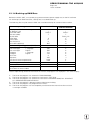
Issue 11/2006
valid for the software versions
TNC 415B/425:
TNC 415F/425E:
TNC 415B/425:
TNC 415F/425E:
NC Software 259 93*
NC Software 259 94*
NC Software 280 54*
NC Software 280 56*
(Standard)
(Export)
(Special Software)
(Export)
Contents Service Manual TNC 415B/425
How to use this Service Manual
Minor Error Messages
Major Error Messages and their Causes
Hardware Components TNC 415B/425
Logic Unit LE 415B/425
Connector Designation and Pin Layout
Block Diagrams
Board Description
Grounding Diagrams TNC 415B/425
Power Supply
Keyboard Unit TE 400/410
Visual Display Unit BC 110/B
Encoders
Electric Handwheels
3D-Touch Probes
Data Interfaces
Data Input and Output
Analogue Outputs
PLC Inputs and Outputs
Test Units
Exchange Instructions
Machine Parameter List
1
2
3
4
5
6
7
8
9
10
11
12
13
14
15
16
17
18
19
20
21
22
SERVICE MANUAL TNC 415B/425
Page 1
Issue: 20.08.95
Table of Contents
Page
1.
How to Use this Service Manual................................................................................ 3
2.
2.1
Minor Error Messages ................................................................................................... 4
Causes of Minor Error Messages ........................................................................................ 5
3.
Major Error Messages and their Causes .................................................................. 7
4.
Hardware Components TNC 415B/425.................................................................... 16
5.
5.1
5.2
5.3
Logic Unit LE 415B/425 ............................................................................................... 17
Designation of the Logic Unit LE 415B/F............................................................................ 17
Designation of the Logic Unit LE 425/E .............................................................................. 18
Hardware Components of the Logic Unit LE 415B/425...................................................... 19
6.
6.1
6.2
6.3
6.4
Connector Designation and Pin Layout .................................................................. 20
Connectors on the Logic Unit LE 415B/425 ....................................................................... 20
Connectors on the PLC I/O Boards..................................................................................... 28
Connectors on the Keyboard Units ..................................................................................... 39
Connectors on the Visual Display Units .............................................................................. 43
7.
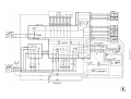
Block Diagrams.............................................................................................................. 45
8.
Board Description ......................................................................................................... 47
9.
Grounding Diagram TNC 415/B ................................................................................. 48
10.
10.1
10.2
10.3
10.4
10.5
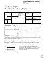
Power Supply ................................................................................................................. 51
External Power Supply Requirements ................................................................................ 51
Power Supply of the NC ..................................................................................................... 53
Checking the Power Supply Unit ........................................................................................ 55
Power Supply of the PLC.................................................................................................... 58
Buffer Battery ...................................................................................................................61.1
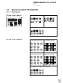
11. Keyboard Unit TE 400/410.......................................................................................... 62
11.1 Overview ............................................................................................................................ 62
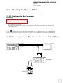
11.2 Checking the Keyboard Unit ............................................................................................... 64
12. Visual Display Unit BC 110/B..................................................................................... 73
12.1 Overview ............................................................................................................................ 73
12.2 Checking the Visual Display Unit ........................................................................................ 73
13.
13.1
13.2
13.3
Encoders .......................................................................................................................... 76
Error Messages for Axes with Analogue Speed Controller ................................................ 76
Error Messages for Axes with Integral Digital Speed Controller ........................................ 78
Electrical Inspection of an Encoder..................................................................................... 80
14.
14.1
14.2
14.3
Electronic Handwheels ................................................................................................ 81
Handwheel HR 130/330...................................................................................................... 81
Handwheel HR 332............................................................................................................ 82
Error Messages .................................................................................................................. 83
SERVICE MANUAL TNC 415B/425
Page 2
Issue: 20.08.95
Page
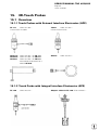
15. 3D-Touch Probes ........................................................................................................... 84
15.1 Overview ............................................................................................................................ 84
15.2 Error Messages .................................................................................................................. 85
16.
16.1
16.2
16.3
16.4
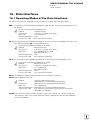
Data Interfaces .............................................................................................................. 87
Operating Modes of the Data Interfaces ............................................................................ 87
Machine Parameters for the Data Interfaces...................................................................... 89
Error Messages .................................................................................................................. 90
Wiring Diagrams of the Data Interfaces.............................................................................. 95
17.
17.1
17.2
17.3
17.4
Data Input and Output ................................................................................................. 97
Data Transfer Menu ............................................................................................................ 97
Overview of Files for TNC 415B/425 .................................................................................. 99
External Data Output .......................................................................................................... 99
Downloading External Data ............................................................................................... 110
18.
18.1
18.2
18.3
18.4
18.5
18.6
Analogue Outputs ........................................................................................................ 120
Specifications..................................................................................................................... 120
Checking the Analogue Outputs ........................................................................................ 120
Switching Over the Position Display.................................................................................. 124
Adjustment of the Feed Rate ............................................................................................ 125
Offset Adjustment ............................................................................................................. 126
Oscilloscope Function........................................................................................................ 129
19.
19.1
19.2
19.3
19.4
19.5
19.6
PLC Inputs and Outputs ............................................................................................. 133
PLC Inputs ......................................................................................................................... 133
PLC Outputs ...................................................................................................................... 133
Checking the PLC Inputs and Outputs .............................................................................. 134
Diagnosis Possibilities in the PLC Mode............................................................................ 137
Compiling the PLC Program............................................................................................... 142
Output "Control Ready for Operation" and Acknowledgement for Test
" Control Ready for Operation " .......................................................................................... 143
20.
20.1
20.2
20.3
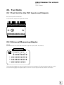
Test Units ....................................................................................................................... 145
Test Unit for the PLC Inputs and Outputs ......................................................................... 145
Universal Measuring Adapter............................................................................................. 145
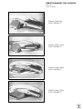
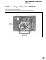
Encoder Diagnostic Set ..................................................................................................... 147
21.
21.1
21.2
21.3
21.4
21.5
21.6
21.7
21.8
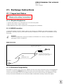
Exchange Instructions ................................................................................................ 148
Important Notes................................................................................................................. 148
Exchanging the Logic Unit ................................................................................................. 154
Exchanging the Processor Board ....................................................................................... 156
Exchanging the CLP Board ................................................................................................ 158
Exchanging the PLC Graphics Board ................................................................................. 161
Exchanging the Power Supply Unit ................................................................................... 163
Exchanging the PLC I/O Boards......................................................................................... 165
Exchanging the EPROMs .................................................................................................. 169
22.
Machine Parameter List ............................................................................................. 170
SERVICE MANUAL TNC 415B/425
Page 3
Issue: 20.08.95
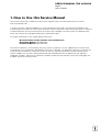
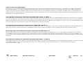
1. How to Use this Service Manual
The service manual TNC 415B/425 can be used to diagnose, locate and eliminate errors on machine
tools controlled by TNC.
In order to correctly judge the problems in an NC-controlled machine tool, fundamental knowledge of the
machine tool and its drives as well as their interaction with the control and the measuring systems is required.
Incorrect behaviour of the machine tool can also result from improper use of the control, NC-programming
errors and incorrect or not properly optimized machine parameters.
For further information in this respect please refer to the
• Documentation of the machine tool manufacturer
• Operating Manual (HEIDENHAIN)
• Technical Manual (HEIDENHAIN).
The Technical Manual is not enclosed with every control. In general, it is only supplied to the machine tool
manufacturer and is updated by HEIDENHAIN, Traunreut. Therefore, it is absolutely necessary to contact the
machine tool manufacturer, if errors occur that are due to a machine parameter or to the interface of the
control. Support will, however, also be provided by the HEIDENHAIN service department and agencies.
Telephone numbers, addresses and telex/fax numbers can be found on the back side of the cover page and
the back side of the service manual.
SERVICE MANUAL TNC 415B/425
Page 4
Issue: 20.08.95
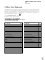
2. Minor Error Messages
TNC 415B/425 features a comprehensive integral monitoring system to avoid input and operation errors,
to locate errors and technical defects of the entire equipment (TNC, measuring systems, machine tool,
cables etc.). The monitoring system is a fixed component of the TNC hardware and software; it is always
active when the control is switched on. If a technical defect or an operation error is detected, an error
message in plain language is displayed on the screen.
To erase minor error messages, press
CE
.
Further error messages are described in the
•
•
•
•
Operating Manual TNC 407/415B/425
Technical Manual TNC 407/415/425
Documentation by the machine tool manufacturer
Operating Instructions FE 401 B.
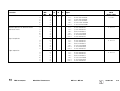
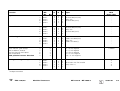
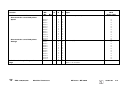
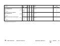
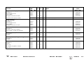
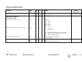
Error Message
Sec.
Error Message
Sec.
AXIS DOUBLE PROGRAMMED
START POSITION INCORRECT
TOUCH POINT INACCESSIBLE
RANGE EXCEEDED
OPERATING PARAMETERS ERASED
BAUD RATE NOT POSSIBLE
CYCL PARAMETER INCORRECT
FAULTY RANGE DATA
ROTATION NOT PERMITTED
DATA MEDIUM MISSING
DATA MEDIUM EMPTY
DATA MEDIUM WRITE-PROTECTED
LIMIT SWITCH <AXIS>
PLANE WRONGLY DEFINED
EMERGENCY STOP
EXT. IN-/OUTPUT NOT READY
ERR: 001
ERR: 002
ERR: 003
ERR: 004
ERR: 005
ERR: 006
ERR: 007
ERR: 010
ERR: 011
ERR: 012
ERR: 013
ERR: 014
ERR: 015
ERR: 016
ERR: 017
ERR: 018
ERR: 100
ERR: 101
15.2
15.2
15.2
15.2
2.1
16.3
15.2
15.2
15.2
16.3
16.3
16.3
2.1
15.2
19.6
16.3
16.3
16.3
16.3
16.3
16.3
16.3
16.3
16.3
16.3
16.3
16.3
16.3
16.3
16.3
16.3
16.3
16.3
16.3
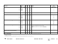
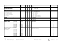
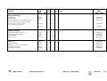
ERR: 102
ERR: 103
ERR: 104
ERR: 105
ERR: 106
ERR: 107
ERR: 108
ERR: 109
PROGRAM DATA ERRONEOUS
WRONG OPERATING MODE
WRONG AXIS PROGRAMMED
HANDWHEEL ?
HANDWHEEL DEFECTIVE
ME: TAPE END
SCALING FACTOR NOT PERMITTED
PLC PROGRAM NOT TRANSLATED
PLC: ERROR <00 to 99>
POSITIONING ERROR
PROGRAM INCOMPLETE
POWER INTERRUPTED
INTERFACE ALREADY ASSIGNED
RELAY EXT. DC VOLTAGE MISSING
STYLUS ALREADY IN CONTACT
PROBE SYSTEM NOT READY
EXCHANGE TOUCH PROBE BATTERY
TRANSFERRED VALUE ERRONEOUS X
TRANSFERRED DATA INCORRECT X
TIME LIMIT EXCEEDED
16.3
16.3
16.3
16.3
16.3
16.3
16.3
16.3
16.3
16.3
15.2
14.3
14.3
16.3
15.2
2.1
2.1
2.1
16.3
2.1
16.3
19.6
15.2
15.2
15.2
16.3
16.3
15.2
SERVICE MANUAL TNC 415B/425
Page 5
Issue: 20.08.95
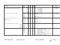
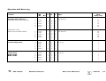
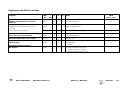
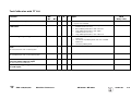
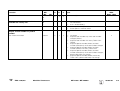
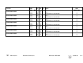
2.1 Causes of Minor Error Messages
OPERATING PARAMETERS ERASED
-
With new and exchange controls, the machine parameters are always erased
Defective buffer batteries, accumulator or capacitor
RAM error on the processor board
Software exchanged
LIMIT SWITCH <AXIS>
-
"Manual" Operating Mode
The preset software limit switch has been reached during traverse with the axis address keys.
"Automatic" Operating Mode
The calculated position of the current block is beyond the software limit switch range or beyond the
additional limit (set with the MOD function <AXIS LIMIT>). The positioning is not performed.
Machine Parameters for the Software Limit Switches
Default setting
1)
Activation via PLC
1)
Activation via PLC
X+
910.0
911.0
912.0
X920.0
921.0
922.0
Y+
910.1
911.1
912.1
Y920.1
921.1
922.1
Default setting
1)
Activation via PLC
1)
Activation via PLC
IV+
910.3
911.3
912.3
IV920.3
921.3
922.3
V+
910.4
911.4
912.4
V920.4
921.4
922.4
1)
Z+
910.2
911.2
912.2
PLC markers M 2816 and M 2817
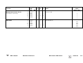
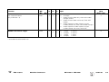
POWER INTERRUPTED
-
After a reset signal of the power supply (e.g. line voltage drops)
Important machine parameters may have been changed:
e.g. MP 210, MP 410.3, MP 730, MP 3240.1, MP 7210, MP 7310
POSITIONING ERROR
-
The servo lag monitor set in the machine parameters 1410.X or 1710.X has responded.
(Check the run-in behaviour of the axis; readjust, if necessary.)
PLC PROGRAM NOT TRANSLATED
- After editing, the PLC program must be compiled (translated) anew.
Z920.2
921.2
922.2
SERVICE MANUAL TNC 415B/425
Page 6
Issue: 20.08.95
PLC: ERROR 00
to
PLC: ERROR 99
marker
2924
to
marker
— set
3023
- Instead of PLC: ERROR 00 to 99 another dialogue may be displayed with customized PLC programs.
For further information please contact your machine tool manufacturer.
NOTES
SERVICE MANUAL TNC 415B/425
Page 7
Issue: 20.08.95
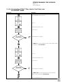
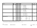
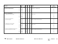
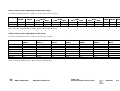
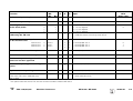
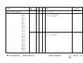
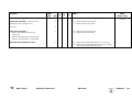
3. Major Error Messages and their Causes
The integrated monitoring system distinguishes between minor and gross errors. Gross errors are
characterized by a blinking display (e.g. malfunctions of the encoders, of the drives and data processing
errors).
If a gross error occurs, the control opens the contact "Control Ready for Operation". This causes an
emergency stop of the machine tool.
END
By switching off the main switch or by pressing
the error cause has been eliminated.
, the emergency stop state can be reset, provided that
Display (blinking)
Error Cause
PROCESSOR CHECK ERROR YX
X= 0
1
2
3
4
5
6
7
8
9
A
B
CRC sum control data incorrect
CRC sum machine parameters incorrect
Check sum NC-memory incorrect
Test plane incomplete / will not run
Crosstalk between data bits in RAM
Crosstalk between addresses in RAM
Stack overflow
CRC sum PLC program ASCII
CRC sum PLC program OP-Code
CRC sum test section
Software error
Wrong interrupt
Differentiation with register V0:
08 bus error
0C address error
10 illegal instruction
14 division by 0
18 error output for CHK command
(check range)
20 error output for TRAPV command
(trap on overflow)
24 privilege infringement (supervisor
command in the user mode)
28 emulator trap
2C emulator trap
30 34 38 3C interrupt vector not initialized
40 interrupt vector not initialized
44 interrupt vector not initialized
48 interrupt vector not initialized
4C 50 54 58 5C 60 false interrupt (with priority 0)
64-7C interrupt auto-vector 4-7,
user interrupt $100-$3FC
94-BC TRAP #5 - #15
SERVICE MANUAL TNC 415B/425
Page 8
Issue: 20.08.95
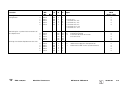
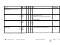
Display (blinking)
Error Cause
C
D
E
F
G
H
I
PROCESSOR CHECK ERROR YX
(continued)
J
K
L
M
N
O
P
Q
R
Y=
Time slice overflow
Command stack overflow control loop
Wrong command main processor
Wrong display mode main processor
Wrong boot command
Verify error with boot command "load"
Wrong supplementary command with boot
command "test"
Boot logon not successful
EPROM comparison CLP
Wrong command CLP processor
Operating voltage beyond tolerance range
No PLC texts in PLC chip
Axis 4 and/or 5 paraxial with export version
Inhibited software function activated
(function without software enable module)
TNC 415 without CLP or geometry CPU
The control attempted to start a
PLC positioning (M2704 to M2708),
a datum shift (M2716) or to switch the
range (M2816 and M2817), although
MP7440/bit 2 was set or MP3030 ≤ 1.
CPU number
1 = main processor
2 = geometry processor
3 = CLP processor
If the error message PROCESSOR CHECK ERROR XY (XY = code; see above) comes up repeatedly, send
the complete logic unit to HEIDENHAIN for repair. Please indicate the error message and the code.
SERVICE MANUAL TNC 415B/425
Page 9
Issue: 28.10.00
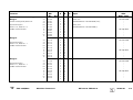
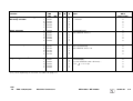
Display (blinking)
ERROR IN PLC-PROGRAM XX
Error Cause
XX = 1A
1B
1C
1D
1E
1F
1G
1H
1I
1J
1K
1L
1M
1N
1O
1P
1Q
1R
2A
2B
2C
2D
2E
2F
2G
2H
2I
2K
2L
2M
2N
2P
50
51
52
53
54
55
1) Only active with compatibility mode TNC 355
NC start
Rapid traverse
Axis address key latch
Feed enable
PLC positioning X 1)
PLC positioning Y 1)
PLC positioning Z 1)
PLC positioning IV 1)
Axis address key X+
Axis address key XAxis address key Y+
Axis address key YAxis address key Z+
Axis address key ZAxis address key IV+
Axis address key IVMore than one of the markers
M2485...M2487 (M03, M04,
M05) are set simultaneously
More than one of the
functions "PLC Positioning"
(M2704 to M2708), "Datum
Shift" (M2716) or "Q-Parameter Transfer" are activated
simultaneously.
Jog increment pos. X+
Jog increment pos. XJog increment pos. Y+
Jog increment pos. YJog increment pos. Z+
Jog increment pos. ZJog increment pos. IV+
Jog increment pos. IVJog increment pos. V+
Jog increment pos. V-
complement missing
complement missing
complement missing
complement missing
complement missing
complement missing
complement missing
complement missing
complement missing
complement missing
complement missing
complement missing
complement missing
complement missing
complement missing
complement missing
complement missing
complement missing
complement missing
complement missing
complement missing
complement missing
complement missing
complement missing
complement missing
complement missing
complement missing
Axis address key V+
complement missing
Axis address key Vcomplement missing
PLC positioning V
complement missing
Excessive nesting (too many modules nested inside
one another)
Stack underflow (an attempt to acquire data from the
STACK, although it was empty)
Stack overflow (an attempt to load too many data
onto the STACK)
Time-out (the permissible program run-time has been
exceeded by more than twice. Check the structure of
the subprogram)
CASE arguments are larger than the number of
entries in the table
No access to error texts / dialogue texts
SERVICE MANUAL TNC 415B/425
Page 10
Issue: 20.08.95
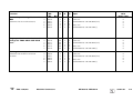
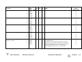
Display (blinking)
ERROR IN PLC-PROGRAM X
Error Cause
X=
7
8
9
ERROR IN PLC-PROGRAM XX
XX = 10
11
12
13
14
15
16
17
18
19
20
21
22
Called label not defined
No end-program condition found (the program does
not contain an EM instruction, or it contains a JP
instruction without a LBL instruction following.)
Program is too long (RAM overflow) (insufficient
memory for the program code to be generated.)
Assign with parenthesis (an =, S, SN, R, RN or PS
instruction has been programmed, although arithmetic
parenthesis are open)
Excessive nesting of parentheses (more than 16
parentheses are open)
Jump within a gating sequence (unconditional jump
has been programmed, although the gating sequence
was not closed with an Assign)
"Close Parenthesis" without "Open Parenthesis" (a
"Close Parenthesis" command was programmed,
although no parentheses were open)
Label within parentheses (a LBL instruction has been
programmed, although parentheses are open)
Label within a gating sequence (a LBL instruction has
been programmed, although the previous gating was
not closed with an Assign)
Jump within parentheses (a jump instruction has been
programmed, although parentheses are open)
Parentheses open at the end of a block (an EM
instruction has been programmed, although
parentheses are open)
Label defined twice
Logic Assign missing (a Word Assign or gating has
been programmed, although the previous Logic-gating
was not closed with a Assign)
Logic Assign missing (a Word instruction has been
programmed, although the previous Logic-gating was
not closed with an Assign)
Word accumulator not loaded (a Word Assign or
gating has been programmed, although the Logic
accumulator does not contain a definite value)
Logic accumulator not loaded (a Logic has been
programmed, although the Logic accumulator does
not contain a definite value)
SERVICE MANUAL TNC 415B/425
Page 11
Issue: 20.08.95
Display (blinking)
ERROR IN PLC-PROGRAM XX
Error Cause
23
(continued)
24
25
26
27
NOTES
Accumulators not loaded on "Open Parentheses"
(an A[, AN[, O[, ON[, XON[ command has been
programmed, although neither the word nor the logic
accumulator has been gated or loaded)
Incorrect type of parentheses result (a different type
has been calculated in the parentheses from that which
was defined in the "Open Parentheses" command, i.e.
logic instead of word or vice versa)
Conditional jump with incorrect logic accumulator
(a conditional jump has been programmed, although the
logic accumulator does not contain a definite value)
Empty CASE instruction
"END-CASE" missing
SERVICE MANUAL TNC 415B/425
Page 12
Issue: 20.08.95
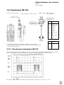
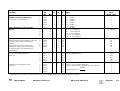
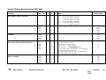
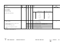
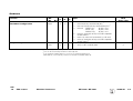
Error Messages GROSS POSITIONING ERROR:
Axes with Analogue Speed Controller
Display (blinking)
GROSS POSITIONING ERROR
<AXIS> YA
GROSS POSITIONING ERROR
<AXIS> YB
GROSS POSITIONING ERROR
<AXIS> YC
GROSS POSITIONING ERROR
<AXIS> YD
GROSS POSITIONING ERROR
<AXIS> YE
Error Cause
Positioning (Servo Lag) Monitoring
- Operation with feed forward control:
position monitoring range exceeded
(range defined in MP1420.X)
- Operation with servo lag:
servo lag monitoring range exceeded
(range defined in MP1720.X)
- Operation with gantry axes:
positions of master and slave axes deviate by more than
the value set in MP855.X. (displayed axis = slave axis)
Monitoring of the Analogue Voltage Limit
- The nominal voltage calculated by the control has
reached its limit of ± 10 V (± 20 V for spindle).
(only with feed forward control)
Movement Monitoring
- The path actually traversed in a certain time is less than
¼ of or more than 4x the nominal value calculated by the
control. (can be influenced via MP1140.x)
Standstill Monitoring
- The deviation from the nominal position of an axis in
standstill has exceeded the value programmed in the
machine parameter MP1110.x.
Monitoring of the Offset Voltage
- The offset voltage limit of 100mV has been reached
during an automatic offset adjustment with MP1220.
(see section 18.5)
Y = CPU number
1 = main processor
2 = geometry processor
3 = CLP processor
Error Location
When the error message GROSS POSITIONING ERROR is displayed, the error may be located in any
element of the closed loop.
e.g.- Error in control (e.g. CLP board)
- Excessive offset voltage at the servo amplifier
- Incorrect speed adjustment at the servo amplifier
- Monitoring function of servo amplifier has responded
(e.g. monitoring of current intensity)
- Electrical defect at the servo amplifier
- Mechanical error (bearing, spindle, guides)
- Excessive mechanical forces on a drive
SERVICE MANUAL TNC 415B/425
Page 13
Issue: 20.08.95
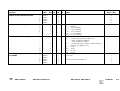
Error Messages GROSS POSITIONING ERROR:
Axes with Integrated Digital Speed Controller
Display (blinking)
GROSS POSITIONING ERROR
<AXIS> YA
GROSS POSITIONING ERROR
<AXIS> YB
GROSS POSITIONING ERROR
<AXIS> YC
GROSS POSITIONING ERROR
<AXIS> YD
GROSS POSITIONING ERROR
<AXIS> YE
GROSS POSITIONING ERROR
<AXIS> YF
Error Cause
Positioning (Servo Lag) Monitoring
- Operation with feed forward control:
position monitoring range exceeded
(range defined in MP1420.X)
- Operation with servo lag:
servo lag monitoring range exceeded
(range defined in MP1720.X)
- Operation with gantry axes:
positions of master and slave axes deviate by more than
the value set in MP855.X. (displayed axis = slave axis)
Monitoring of the Analogue Voltage Limit
- The nominal voltage calculated by the control has
reached its limit of ± 10 V (± 20 V for spindle).
(only with feed forward control)
Movement Monitoring
- The difference between the path information of the
position encoder (LS) and that of the speed encoder
(ROD) has reached the tolerance limit defined in
MP1970.x.
Standstill Monitoring
- The deviation from the nominal position of an axis in
standstill has exceeded the value programmed in the
machine parameter MP1110.x.
Monitoring of the Offset Voltage
- The offset voltage limit of 100mV has been reached
during an automatic offset adjustment with MP1220.
(see section 18.5)
Monitoring of the Integrated Digital Speed
Controller
- The monitoring limit of the integrated speed controller
(MP1910.x) has responded.
Y = CPU number
1 = main processor
2 = geometry processor
3 = CLP processor
Error Location
When the error message GROSS POSITIONING ERROR is displayed, the error may be located
in any element of the closed loop.
e.g.: - Error in control (e.g. CLP board)
- Excessive offset voltage at the servo amplifier
- Monitoring function of servo amplifier has responded
(e.g. monitoring of current intensity)
- Electrical defect at the servo amplifier
- Motor, tachometer, encoder or cabling defective
- Mechanical error (bearing, spindle, guides)
- Excessive mechanical forces on a drive
SERVICE MANUAL TNC 415B/425
Page 14
Issue: 20.08.95
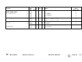
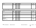
Display (blinking)
Error Cause
ENCODER <AXIS> DEFECTIVE YA
Signal amplitude error
position encoder
ENCODER <AXIS> ` DEFECTIVE YA
Signal amplitude error
speed encoder
ENCODER <AXIS> DEFECTIVE YB
Signal frequency error
position encoder
ENCODER <AXIS> ` DEFECTIVE YB
Signal frequency error
speed encoder
ENCODER <AXIS> DEFECTIVE YC
Error with distance-coded scale
position encoder
ENCODER <AXIS> `DEFECTIVE YC
Error with distance-coded scale
speed encoder
Y = CPU number
1 = main processor
2 = geometry processor
3 = CLP processor
Error Causes:
- Encoder not connected
- Cable damaged
- Glass scale contaminated or damaged
- Scanning head defective
- Encoder monitoring system defective
Checking the encoders: see section 13
WRONG REFERENCE POINT
Wrong reference mark spacing entered with distancecoded linear encoders (counting error caused by the
measuring system or the logic unit)
TNC OPERATING TEMP. EXCEEDED
Temperature inside the logic unit has exceeded + 70°C
EMERG. STOP DEFECTIVE YX
YX = 1( 1. emergency stop test
1) 2. emergency stop test
1. 3. emergency stop test
- Error during the test routine "Control ready for operation"
when the machine is switched on (see section 19.4)
EMERGENCY STOP PLC
This error message is only generated, if the marker 2815
is set without additional marker (M2924 - M3023).
SERVICE MANUAL TNC 415B/425
Page 15
Issue: 20.08.95
Display (blinking)
PLC: Error 00
Error Cause
1)
to
PLC: Error 99
CHECK SUM ERROR YX
marker
2924
to
1)
marker
— and marker 2815 set
3023
TNC 407:
1A
1B
1D
1X
CRC sum main processor EPROM chips 1/2
CRC sum main processor EPROM chips 3/4
CRC sum PLC chip
Check sum calculation
TNC 415A:
YA
YC
YD
YE
YR
1X
CRC sum main processor EPROM chips 1 to 4
CRC sum geometry processor EPROM chips 5/6
CRC sum PLC chip
CRC sum GEM chip 7
CRC sum CLP boot chip
Check sum calculation
TNC 415B,
TNC 425:
YA
YB
YC
YD
YE
YR
1X
CRC sum main processor EPROM chips 1/2
CRC sum main processor EPROM chips 3/4
CRC sum geometry processor EPROM chips 5/6
CRC sum PLC chip
CRC sum GEM chip 7
CRC sum CLP boot chip
Check sum calculation
Y=
CPU number
1 = main processor
2 = geometry processor
3 = CLP processor
1)
Instead of PLC: ERROR 00 ... 99 another dialogue may be displayed with customized PLC programs.
For further information, please contact your machine tool manufacturer.
CRC = Cyclic Redundancy Check (during data transfer)
If the error message CHECK SUM ERROR YX comes up repeatedly, send the complete logic unit to
HEIDENHAIN for repair. Please indicate the check sum error.
SERVICE MANUAL TNC 415B/425
Page 16
Issue: 20.08.95
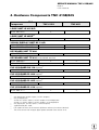
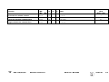
4. Hardware Components TNC 415B/425
TNC
Component
TNC 415 B
LOGIC UNIT LE 415 B/F
Id.No. 267 223 --
TNC 425
6)
x
6(7)
LOGIC UNIT LE 425/E
Id.No. 267 214 --
x
VISUAL DISPLAY UNIT BC 110/B
Id.No. 260 520 -- (BC 110B)
Id.No. 254 740 -- (BC 110)
KEYBOARD UNIT TE 400
Id.No. 250 517 --
x
x 5)
x
x 5)
x
x
KEYBOARD UNIT TE 410 (customized version)
Id.No. 258 645 -x
Id.No. 264 105 -x
x
x
2)
PLC I/O BOARD PA 110 (option)
Id.No. 262 651 --
x
x
x
x
x
x
x
x
1)
PLC I/O BOARD PL 400 (option)
Id.No. 255 855 --
4)
PLC I/O BOARD PL 405 (option)
Id.No. 263 371 21
3)
PLC I/O BOARD PL 410 (option)
Id.No. 263 371 --
1)
2)
3)
4)
5)
6)
7)
only digital part (64 PLC inputs / 32 PLC outputs)
only analogue part
version 01: 64 PLC inputs / 23 PLC outputs and analogue part
version 11: 64 PLC inputs / 23 PLC outputs, no analogue part
only digital part: (32 PLC inputs / 16 PLC outputs)
superseded by BC 110B
F/E: export versions of the controls (different software; hardware identical)
TNC 425: control with integral digital speed controller (see section 18.2)
SERVICE MANUAL TNC 415B/425
Page 17
Issue: 20.08.95
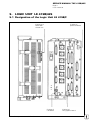
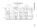
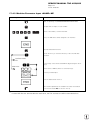
5. LOGIC UNIT LE 415B/425
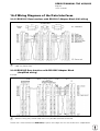
5.1 Designation of the Logic Unit LE 415B/F
ID plate and
PGM label
of logic unit
ID plate of
processor board
ID plate of
CLP board
LE 415F = export version of LE 415B
ID plate of
PLC graphics board
SERVICE MANUAL TNC 415B/425
Page 18
Issue: 20.08.95
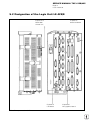
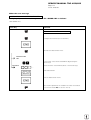
5.2 Designation of the Logic Unit LE 425/E
ID plate and
PGM label
of logic unit
ID plate of
processor board
ID plate of
CLP board
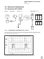
LE 425E= export version of LE 425
ID plate of
PLC graphics board
SERVICE MANUAL TNC 415B/425
Page 19
Issue: 20.08.95
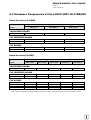
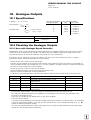
5.3 Hardware Components of the LOGIC UNIT LE 415B/425
Board Overview LE 415B/F
Board
LE 415B/F
267 223 --
TNC 415B/F
LE 415B/F
267 223 3-
LE 415B/F
267 223 4-
x
x
x
x
x
PROCESSOR BOARD
Id.No. 268 553 01
PLC GRAPHICS BOARD
Id.No. 257 954 02
Id.No. 257 954 03*
x
CLP BOARD
Id.No. 275 705 01
Id.No. 275 705 02
x
x
x
Board Overview LE 425/E
Board
LE 425/E
267 214 1-
TNC 425/E
LE 425/E
267 214 3-
LE 425/E
267 214 4-
LE 425/E
267 214 5-
x
x
x
x
x
x
x
LE 425/E
267 214 2-
PROCESSOR BOARD
Id.No. 268 553 01
x
PLC GRAPHICS BOARD
Id.No. 257 954 02
Id.No. 257 954 03*
x
x
CLP BOARD
Id.No. 265 401 01
Id.No. 268 927 01
Id.No. 275 711 01
Id.No. 275 711 02
x
x
x
x
x
* +24V supply voltage of the operating panel (routed via X46) cannot be switched off with EMERG. STOP.
SERVICE MANUAL TNC 415B/425
Page 20
Issue: 20.08.95
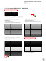
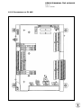
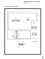
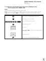
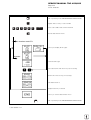
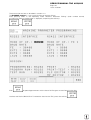
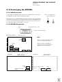
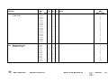
6. Connector Designation and Pin Layout
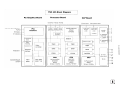
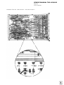
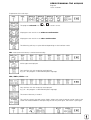
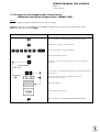
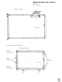
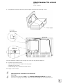
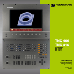
6.1 Connectors on the LOGIC UNIT LE 415B/425
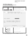
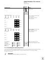
6.1.1 Connector Designation LOGIC UNIT LE 415B/425
LE 415B
Power
Supply
CLP
Board
PLC
Graphics
Board
Processor
Board
CLP board
X1 = measuring system 1 (∼)
X2 = measuring system 2 (∼)
X3 = measuring system 3 (∼)
X4 = measuring system 4 (∼)
X5 = measuring system 5 (∼)
X6 = measuring system S ( )
X8 = nominal value output 1, 2, 3, 4, 5, S
X12 = triggering touch probe
X14 = measuring touch probe
B = signal ground
PLC graphics board
X41 = PLC output
X42 = PLC input
X43 = visual display unit (BC)
X44 = 24V power supply for PLC
X45 = TNC keyboard unit (TE)
X46 = machine operating panel
X47 = PLC I/O board
Processor board
X21 = RS-232-C data interface
X22 = RS-422 data interface
X23 = electronic handwheel
X31 = 24V- power supply for NC
SERVICE MANUAL TNC 415B/425
Page 21
Issue: 20.08.95
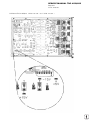
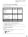
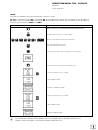
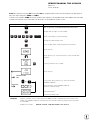
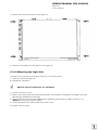
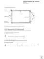
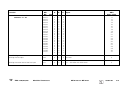
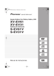
LE 425
Power
Supply
CLP
Board
PLC
Graphics
Board
Processor
Board
CLP Board
X1 = encoder 1 (∼)
X2 = encoder 2 (∼)
X3 = encoder 3 (∼)
X4 = encoder 4 (∼)
X5 = encoder 5 (∼)
)
X6 = encoder S (
X8 = nominal value output 1, 2, 3, 4, 5, S
X12 = touch trigger probe
X14 = measuring touch probe
X15 = encoder / speed
X16 = encoder / speed
X17 = encoder / speed
X18 = encoder / speed
X19 = encoder / speed
X20 = reserved
B = signal ground
PLC Graphics Board
X41 = PLC output
X42 = PLC input
X43 = visual display unit (BC)
X44 = 24 V power supply for PLC
X45 = TNC operating panel (TE)
X46 = machine operating panel
X47 = PLC I/O interface
Processor Board
X21 = V.24/RS-232-C data interface
X22 = V.11/RS-422 data interface
X23 = electronic handwheel
X31 = 24V- power supply for NC
SERVICE MANUAL TNC 415B/425
Page 22
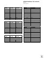
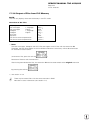
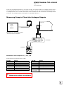
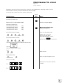
Issue: 14.11.06
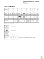
6.1.2 Pin Layout: POWER SUPPLY LE 415B/425
X31 Power Supply (NC)
terminal strip (pluggable) 2-pin
Pin No.
1
2
Assignment
+ 24 V
0V
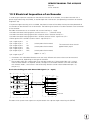
6.1.3 Pin Layout: CLP Board LE 415 B
X1,X2,X3,X4,X5 Encoders 1,2,3,4,5
(Position)
sinusoidal input,
current interface 7-16µA
flange socket with female insert (9-pin, Conei)
X6 Spindle Encoder (Position)
Pin No.
1
2
5
6
7
8
3
4
9
housing
Pin No.
5
6
8
1
3
4
7
(2)
12
(11)
10
9 (via spring)
Assignment
0°+
0°90°+
90°RP+
RP+ 5 (Up)
0 V (Uusable comp.)
internal shield
external shield = housing
square-wave encoder (TTL)
flange socket with female insert (12-pin, Conei)
Signal Designation
Ua1
-Ua1
Ua2
-Ua2
Ua0
-Ua0
-UaS
+ 5V (sense)
+ 5V (Up)
0 V (sense)
0 V (Uusable comp.)
shield = housing
X8 Nominal Value Output 1,2,3,4,5,S
flange socket with female insert
(15-pin, D-SUB)
X12 Touch Trigger Probe
flange socket with female insert
(15-pin, D-SUB)
Pin No.
1
3
5
7
4
8
9
11
13
14
6
15
housing
2,10,12
Pin No.
1
3
4
5
6
7
8
9
10
2, 11 to 15
Signal Designation
analogue output 1
analogue output 2
analogue output 3
analogue output 4
analogue output 5
analogue output spindle
0V analogue output 1
0V analogue output 2
0V analogue output 3
0V analogue output 4
0V analogue output 5
0V analogue output spindle
external shield = housing
do not assign
Signal Designation
internal shield
standby
start
+ 15V
+ 5V (Up)
-battery warning
0 V (Uusable comp.)
trigger signal
-trigger signal 1)
not assigned
1) stylus at rest = high level
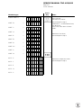
SERVICE MANUAL TNC 415B/425
Page 23
Issue: 20.08.95
X14 Measuring Touch Probe
flange socket with female insert (25-pin, D-SUB)
Pin No.
17
4
16
3
14
2
15
1
21
8
20
7
18
6
19
5
25
12
24
11
22
10
23
9
13
Assignment
0° +
0° 90° +
90° RP +
RP + 5V
0V
0° +
0° 90° +
90° RP +
RP + 5V
0V
0°+
0°90°+
90°RP +
RP + 5V
0V
shield
6.1.4 Pin Layout: CLP Board LE 425
X1, X2, X3, X4, X5 Encoder 1, 2, 3, 4, 5
(Position)
sinusoidal input
current interface 7 - 16µA
flange socket with female insert (9-pin, D-SUB)
Pin No.
6
1
8
3
9
5
7
2
3
housing
Assignment
0° +
0° 90° +
90° RP +
RP + 5V (UP)
0V (UN)
internal shield
external shield = housing
X8 Nominal Value Output 1, 2, 3, 4, 5, S
see CLP board LE 415 B
X14 Measuring Touch Probe
see CLP board LE 415 B
X6 Spindle Encoder (Position)
square-wave input (TTL)
flange socket with female insert (15-pin, D-SUB)
Pin No.
1
9
3
11
14
7
13
12
10
4
2
5, 6, 8, 15
housing
Assignment
Ua1
-Ua1
Ua2
-Ua2
Ua0
-Ua0
-UaS
+ 5V sense
0V sense
+ 5V (UP)
0V (UN)
not assigned
external shield = housing
X12 Touch Trigger Probe
see CLP board LE 415 B
SERVICE MANUAL TNC 415B/425
Page 24
Issue: 20.08.95
X15, X16, X17, X18, X19 Encoder 1,2,3,4,5 (Speed)
sinusoidal input,
voltage interface 1Vpp
flange socket with female insert (15-pin, D-SUB)
Pin No.
1
9
3
11
14
7
4
2
(12)
(10)
5,6,8,13,15
housing
Assignment
A+
AB+
BR+
R+ 5V (UP)
0V (UN)
+ 5V sense
0V sense
do not assign
external shield = housing
6.1.5 Pin Layout: PLC Graphics Board LE 415B/425
X44 Power Supply (PLC)
terminal strip (pluggable) 3-pin
.
Pin No.
1
2
3
Assignment
+ 24V_A can be switched off via
EMERG. STOP
+ 24V cannot be switched off
via EMERG. STOP
0V
X41 PLC Output
flange socket with female insert (37-pin, D-SUB)
Pin No.
1
2
3
4
5
6
7
8
9
10
11
12
13
14
15
16
17
18
19
20
Assignment
O0
O1
O2
O3
O4
O5
O6
O7
O8
O9
O10
O11
O12
O13
O14
O15
O16
O17
O18
O19
X42 PLC Input
flange socket with female insert (37-pin, D-SUB)
Pin No.
Assignment
21
O20
22
O21
23
O22
24
O23
25
O24 2)
26
O25 2)
27
O26 2)
28
O27 2)
29
O28 2)
30
O29 2)
31
O30 2)
32
do not assign
33
0V (PLC) 1)
34
control ready for operation 2)
35,36,37
+24V_A PLC 3)
housing
external shield
1) 0 V PLC reference potential for testing
2) cannot be switched off with ext. EMERG. STOP
3) + 24V_A PLC power supply for testing
(can be switched off)
X45 TNC Operating Panel (TE)
flange socket with female insert (37-pin, D-SUB)
SERVICE MANUAL TNC 415B/425
Page 25
Issue: 20.08.95
Pin No.
1
2
3
4
5
6
7
8
9
10
11
12
13
14
15
16
17
18
19
20
21
22
23
24
25
26
27
28
29
30
31
32
33,34
35,36,37
housing
1) external
Assignment
I0
I1
I2
I3 acknowledgement for test
"control ready for operation"
I4
I5
I6
I7
I8
I9
I10
I11
I12
I13
I14
I15
I16
I17
I18
I19
I20
I21
I22
I23
I24
I25
I26
I27
I28
I29
I30
I31
do not assign
0V PLC 1)
external shield = housing
reference potential for PLC supply
X43 Visual Display Unit (BC 110/B)
flange socket with female insert (15-pin, D-SUB)
Pin No.
1,8,11
2 to 6,12,13
7
9
10
14
15
Assignment
GND
do not assign
R signal
V SYNC
H SYNC
G signal
B signal
Pin No.
1
2
3
4
5
6
7
8
9
10
11
12
13
14
15
16
17
18
19
20
21
22
23
24
25
26
27
28
29
30
31
32
33
34
35
36
37
housing
Assignment
RL0
RL1
RL2
RL3
RL4
RL5
RL6
RL7
RL8
RL9
RL10
RL11
RL12
RL13
RL14
RL15
key matrix
RL16
RL17
RL18
SL0
SL1
SL2
SL3
SL4
SL5
SL6
SL7
RL19
RL20
do not assign
RL21
RL22
key matrix
RL23
spindle override (wiper)
feed override (wiper)
- 5V override potentiometer
0V override potentiometer
external shield = housing
SERVICE MANUAL TNC 415B/425
Page 26
Issue: 20.08.95
X46 Machine Operating Panel
flange socket with female insert (37-pin, D-SUB)
X47 PLC Expansion Interface
12V interface
flange socket with male insert(25-pin, D-SUB)
Pin No.
1
2
3
4
5
6
7
8
9
10
11
12
13
14
15
16
17
18
19
20
21
22
23
24
25
26
27
28
29
30
31
32
33
34
35
36
37
Pin No.
1,2,3
4
5,6,17,18
7
8
9
10
11
12
13
14,15,16
19
20
21
22
23
24
25
Assignment
I128
I129
I130
I131
I132
I133
I134
I135
I136
I137
I138
I139
I140
I141
I142
I143
I144
I145
I146
I147
I148
I149
I150
I151
I152
1)
O0
1)
O1
1)
O2
1)
O3
1)
O4
1)
O5
1)
O6
1)
O7
0 V (PLC) 2)
0 V (PLC) 2)
+ 24V PLC 3) 4)
+ 24V PLC 3) 4)
1) O0...O7 simultaneously at X21 (PLC output)
2) 0V PLC reference potential for testing
3) + 24 V PLC supply voltage routed via fuse for the inputs
I128 to I152
4) PLC board version 01/02:
PLC board version 03:
+ 24V_A can be switched off
+ 24V cannot be switched off
Assignment
0V*1
serial IN 2
not assigned
-RESET
-WRITE EXTERN
WRITE EXTERN
-O5
-O3
-O1
shield
+ 12V * 1
serial IN 1
EMERGENCY STOP
-serial OUT
serial OUT
-O4
-O2
-O0
SERVICE MANUAL TNC 415B/425
Page 27
Issue: 20.08.95
6.1.6 Pin Layout: Processor Board LE 415B/425
X21 V.24/RS-232 Data Interface
flange socket with female insert (25-pin, D-SUB)
Pin No.
1
2
3
4
5
6
7
8 to 19
20
21 to 25
housing
Assignment
shield
RxD
TxD
CTS
RTS
DTR
GND (0 V * 2)
not assigned
DSR
not assigned
external shield = housing
X22 V.11/RS-422 Data Interface
flange socket with female insert (15-pin, D-SUB)
Pin No.
1
2
3
4
5
6
7
8
9
10
11
12
13
14
15
Assignment
shield
RxD
CTS
TxD
RTS
DSR
DTR
GND
-RxD
-CTS
-TxD
-RTS
-DSR
-DTR
do not assign
X23 Handwheel Interface (serial)
flange socket with female insert (9-pin, D-SUB)
Pin No.
1,3,5
4
2
6
9
8
7
housing
Assignment HR 130/330
not assigned
+ 12V
0V
DTR
not assigned
RXD
do not assign
external shield = housing
Assignment HR 332
not assigned
+ 12V
0V
DTR
not assigned
RXD
TXD
external shield = housing
SERVICE MANUAL TNC 415B/425
Page 28
Issue: 20.08.95
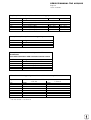
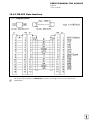
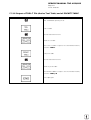
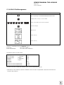
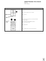
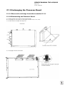
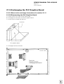
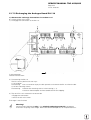
6.2 Connectors on the PLC I/O Boards
6.2.1 Connectors on PL 400
can be switched off
+24V
via EMERG. STOP
X1
X6
12
11
10
9
8
7
6
5
4
3
2
1
X7
12
11
10
9
8
7
6
5
4
3
2
1
X8
12
11
10
9
8
7
6
5
4
3
2
1
X4
X2
1
2
3
4
5
6
7
8
9
10
11
12
X3
+24V
(cannot be switched off
via EMERG. STOP)
X5
12
11
10
9
8
7
6
5
4
3
2
1
121110 9 8 7 6 5 4 3 2 1
1
2
3
4
5
6
7
8
9
10
11
12
1
2
3
4
5
6
7
8
9
10
11
12
X9
X12
0V
6
5
4
3
2
1
X10
from LE
X11
to 2. PLC board
(PL or PA)
SERVICE MANUAL TNC 415B/425
Page 29
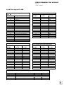
Issue: 20.08.95
6.2.2 Pin Layout: PL 400
X1
Pin No.
1
2
3
4
5
6
7
8
9
10
11
12
Assignment
as 1. PL
O32
O33
O34
O35
O36
O37
O38
O39
O40
O41
O42
do not assign
as 2. PL
064
065
066
067
068
069
070
071
072
073
074
X4
Pin No.
1
2
3
4
5
6
7
8
9
10
11
12
Assignment
as 1. PL
I126
I74
I73
I72
I71
I70
I69
I68
I67
I66
I65
I64
as 2. PL
I254
I202
I201
I200
I199
I198
I197
I196
I195
I194
I193
I192
X2
Pin No.
1
2
3
4
5
6
7
8
9
10
11
12
Assignment
as 1. PL
O43
O44
O45
O46
O47
O48
O49
O50
O51
O52
O53
do not assign
as 2. PL
075
076
077
078
079
080
081
082
083
084
085
X5
Pin No.
1
2
3
4
5
6
7
8
9
10
11
12
Assignment
as 1. PL
I86
I85
I84
I83
I82
I81
I80
I79
I78
I77
I76
I75
as 2. PL
I214
I213
I212
I211
I210
I209
I208
I207
I206
I205
I204
I203
X3
Pin No.
1
2
3
4
5
6
7
8
9
10
11
12
Assignment
as 1. PL
as 2. PL
O54
086
O55
087
O56 1)
088 1)
1)
O57
089 1)
1)
O58
090 1)
1)
O59
091 1)
1)
O60
092 1)
O61 1)
093 1)
O62 1)
094 1)
control ready for operation
do not assign
+24V cannot be switched off
via ext. EMERG. STOP
X6
Pin No.
1
2
3
4
5
6
7
8
9
10
11
12
Assignment
as 1. PL
I98
I97
I96
I95
I94
I93
I93
I91
I90
I89
I88
I87
as 2. PL
I227
I226
I225
I224
I223
I221
I220
I219
I218
I217
I216
I215
1) outputs
cannot be switched off via ext. EMERG. STOP
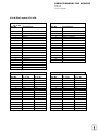
SERVICE MANUAL TNC 415B/425
Page 30
Issue: 20.08.95
X7
Pin No.
1
2
3
4
5
6
7
8
9
10
11
12
Assignment
as 1. PL
I110
I109
I108
I107
I106
I105
I104
I103
I102
I101
I100
I99
as 2. PL
I238
I237
I236
I235
I234
I233
I232
I231
I230
I229
I228
I227
X8
Pin No.
1
2
3
4
5
6
7
8
9
10
11
12
Assignment
as 1. PL
I122
I121
I120
I119
I118
I117
I116
I115
I114
I113
I112
I111
as 2. PL
I250
I249
I248
I247
I246
I245
I244
I243
I242
I241
I240
I239
X9
Pin No.
1
2
3
4
5
6
Assignment
as 1. PL
do not assign
do not assign
do not assign
I125
I124
I123
as 2. PL
I253
I252
I251
X10 Connection to LE or to 1. PL
Pin No.
Assignment
1,2,3
0V
4
serial IN 2
5,6,17,18
not assigned
7
-RESET
8
-WRITE EXTERN
9
WRITE EXTERN
10
-O5
11
-O3
12
-O1
13
shield
14,15
+ 12 V
16
board ID (PK)
19
serial IN 1
20
control ready for operation
21
-SERIAL OUT
22
SERIAL OUT
23
-O4
24
-O2
25
-O0
X11 Connection of 2. PL or PA
Pin No.
Assignment
1,2,3
0V
4-6, 14-18
do not assign
7
-RESET
8
-WRITE EXTERN
9
WRITE EXTERN
10
-O5
11
-O3
12
-O1
13
shield
19
serial IN 2
20
control ready for operation
21
-serial OUT
22
serial OUT
23
-O4
24
-O2
25
-O0
SERVICE MANUAL TNC 415B/425
Page 31
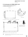
Issue: 20.08.95
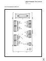
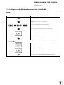
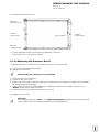
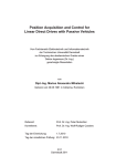
6.2.3 Connectors on PL 405
SERVICE MANUAL TNC 415B/425
Page 32
Issue: 20.08.95
6.2.4 Pin Layout: PL 405
X1 Connection to Logic Unit or
to 1. PL
Pin No.
Assignment
1,2,3
0V
5.6.17.18
do not assign
4
serial IN 2
7
-RESET
8
WRITE EXTERN
9
-WRITE EXTERN
10
-O5
11
-O3
12
-O1
13
shield
14, 15
+12V
16
board ID (PK)
19
serial IN 1
20
control ready for operation
21
-serial OUT
22
serial OUT
23
-O4
24
-O2
25
-O0
X3 PLC Inputs
Assignment
Pin No.
as 1. PL
1
I64
2
I65
3
I66
4
I67
5
I68
6
I69
7
I70
8
I71
9
I72
10
I73
11
I74
12
I75
13
I76
14
I77
15
I78
16
I79
X4 PLC Inputs
X8 PLC Outputs
and "Control Ready for Operation"
Assignment
Pin No.
as 1. PL
as 2. PL
1
O48
O80
2
O49
O81
3
O50
O82
4
O51
O83
5
O52
O84
6
O53
O85
7
O54
O86
8
O55
O87
9
O56
O88
10
O57
O89
11
O58
O90
12
O59
O91
13
O60
O92
14
O61
O93
15
O62
O94
16
control ready for operation
Pin No.
1
2
3
4
5
6
7
8
9
10
11
12
13
14
15
16
Assignment
as 1. PL
I80
I81
I82
I83
I84
I85
I86
I87
I88
I89
I90
I91
I92
I93
I94
I95
X9, X10, X13, X14
Terminal
X9
X10
X13
X14
as 2. PL
I208
I209
I210
I211
I212
I213
I214
I215
I216
I217
I218
I219
I220
I221
I222
I223
PL 405 Power Supply
Assignment
as 1. PL
as 2. PL
0V
+24 V- logic supply and "Control Ready for Operation"
+24 V- output supply
O48 - O55
O80 - O87
+24 V- output supply
O56 - O62
O88 - O94
as 2. PL
I192
I193
I194
I195
I196
I197
I198
I199
I200
I201
I202
I203
I204
I205
I206
I207
SERVICE MANUAL TNC 415B/425
Page 33
Issue: 20.08.95
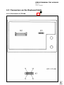
6.2.5 Connectors on PL 410
SERVICE MANUAL TNC 415B/425
Page 34
Issue: 20.08.95
6.2.6 Pin Layout: PL 410
X1 Connection to Logic Unit or
to 1. PL
Pin No.
Assignment
1,2,3
5, 6, 17, 18
4
7
8
9
10
11
12
13
14, 15
16
19
20
21
22
23
24
25
0V
do not assign
serial IN 2
-RESET
-WRITE EXTERN
WRITE EXTERN
-O5
-O3
-O1
shield
+12V
board ID (PK)
serial IN 1
control ready for operation
-serial OUT
serial OUT
-O4
-O2
-O0
X3 PLC Inputs
Assignment
Pin No.
as 1. PL
1
I64
2
I65
3
I66
4
I67
5
I68
6
I69
7
I70
8
I71
9
I72
10
I73
11
I74
12
I75
13
I76
14
I77
15
I78
16
I79
as 2. PL
I192
I193
I194
I195
I196
I197
I198
I199
I200
I201
I202
I203
I204
I205
I206
I207
X2 Connection of 2. PL or PA
Pin No.
1,2,3
4-6, 14 - 18
7
8
9
10
11
12
13
19
20
21
22
23
24
25
Assignment
0V
do not assign
RESET
-WRITE EXTERN
WRITE EXTERN
-O5
-O3
-O1
shield
serial IN 2
control ready for operation
-serial OUT
serial OUT
-O4
-O2
-O0
X4 PLC Inputs
Assignment
Pin No.
as 1. PL
1
I80
2
I81
3
I82
4
I83
5
I84
6
I85
7
I86
8
I87
9
I88
10
I89
11
I90
12
I91
13
I92
14
I93
15
I94
16
I95
as 2. PL
I208
I209
I210
I211
I212
I213
I214
I215
I216
I217
I218
I219
I220
I221
I222
I223
SERVICE MANUAL TNC 415B/425
Page 35
Issue: 20.08.95
X5 PLC Inputs
Assignment
Pin No.
as 1. PL
1
I96
2
I97
3
I98
4
I99
5
I100
6
I101
7
I102
8
I103
9
I104
10
I105
11
I106
12
I107
13
I108
14
I109
15
I110
16
I111
as 2. PL
I224
I225
I226
I227
I228
I229
I230
I231
I232
I233
I234
I235
I236
I237
I238
I239
X6 PLC Inputs
Assignment
Pin No.
as 1. PL
1
I112
2
I113
3
I114
4
I115
5
I116
6
I117
7
I118
8
I119
9
I120 1)
10
I121 1)
11
I122 1)
12
I123 1)
13
I124 1)
14
I125 1)
15
I126 1)
16
I127 1)
as 2. PL
O64
O65
O66
O67
O68
O69
O70
O71
O72
O73
O74
O75
O76
O77
O78
O79
X8 PLC Outputs
and "Control Ready for Operation"
Assignment
Pin No.
as 1. PL
as 2. PL
1
O48
O80
2
O49
O81
3
O50
O82
4
O51
O83
5
O52
O84
6
O53
O85
7
O54
O86
8
O55
O87
9
O56
O88
10
O57
O89
11
O58
O90
12
O59
O91
13
O60
O92
14
O61 1)
O93 1)
15
O62 1)
O94 1)
16
control ready for operation
X7 PLC Outputs
Pin No.
1
2
3
4
5
6
7
8
9
10
11
12
13
14
15
16
1) With
Assignment
as 1. PL
O32
O33
O34
O35
O36
O37
O38
O39
O40
O41
O42
O43
O44
O45
O46
O47
as 2. PL
I240
I241
I242
I243
I244
I245
I246
I247
I248 1)
I249 1)
I250 1)
I251 1)
I252 1)
I253 1)
I254 1)
I255 1)
active analogue inputs (depend on the position of the ENABLE ANALOGUE INPUTS switch on
PL140) these PLC inputs and outputs are not available (see section 21.7.2).
SERVICE MANUAL TNC 415B/425
Page 36
Issue: 20.08.95
X9, X10, X11, X12, X13, X14
Terminal
X9
X10
X11
X12
X13
X14
PL Power Supply
Assignment
as 1. PL
as 2. PL
0V
+24 V- supply of LE and "Control Ready for Operation"
+24 V- output supply
O32 - O39
O64 - O71
+24 V- output supply
O40 - O47
O72 - O79
+24 V- output supply
O48 - O55
O80 - O87
+24 V- output supply
O56 - O62
O88 - O94
X15 1), X16 1), X17 1), X18 1) Analogue Inputs ± 10V
Pin No.
1
2
3
Assignment
voltage input (± 10V)
0V
shield
X19 1), X20 1), X21 1), X22 1) Inputs for PT 100
Thermistors
Four-wire Connector with constant current source
Pin No.
1
2
3
4
5
Assignment
I+
constant current for PT 100
U+ measuring input
Umeasuring input
Iconstant current for PT 100
shield
Allocation of Analogue Inputs to Internal PLC Memory Addresses
Input
X15
X16
X17
X18
X19
X20
X21
X22
1)
W496
W498
W500
W502
W504
W506
W508
W510
not with version 11 of PL 410
Internal Memory Address
1. PL 410
2. PL 410
W464
W466
W468
W470
W472
W474
W476
W478
SERVICE MANUAL TNC 415B/425
Page 37
Issue: 20.08.95
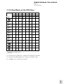
6.2.7 Connectors on PA 110
SERVICE MANUAL TNC 415B/425
Page 38
Issue: 20.08.95
6.2.8 Pin Layout: PA 110
X1 Connection to Logic Unit or
1.PL
Pin No.
Assignment
1, 2, 3
0V
4
serial IN 2
5, 6, 17, 18 do not assign
7
-RESET
8
-WRITE EXTERN
9
WRITE EXTERN
10
-O5
11
-O3
12
-O1
13
shield
14, 15
+ 12V
16
board ID (PK)
19
serial IN 1
20
control ready for operation
21
-serial OUT
22
serial OUT
23
-O4
24
-O2
25
-O0
X2, X3, X4, X5
Analogue Inputs ± 10V
Pin No.
Assignment
1
voltage input (+/- 10 V)
2
0V
3
shield
X6 PA 110 Power Supply
Pin No.
Assignment
1
+24 V
2
0V
X7, X8, X9, X10 Inputs for PT 100
Thermistors
Four-wire connector with const. current source
Pin No.
Assignment
1
I+
constant current for PT100
2
U+ measuring input
3
Umeasuring input
4
Iconstant current for PT100
5
shield
Allocation of Analogue Inputs to Internal PLC Memory Addresses
Input
X2
X3
X4
X5
X7
X8
X9
X10
W496
W498
W500
W502
W504
W506
W508
W510
Internal Memory Address
PA as 1. expansion
PA as 2. expansion
W464
W466
W468
W470
W472
W474
W476
W478
SERVICE MANUAL TNC 415B/425
Page 39
Issue: 20.08.95
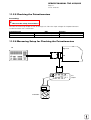
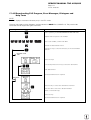
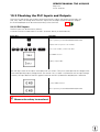
6.3 Connectors on the Keyboard Units
6.3.1 Connectors on TE 400
SERVICE MANUAL TNC 415B/425
Page 40
Issue: 20.08.95
6.3.2 Pin Layout: TE 400
X1 Connection of the Soft Keys
of the VDU
Plug-type connector with female insert (9-pin)
Pin No.
Assignment
1
SL0
2
SL1
3
SL2
4
SL3
5
do not assign
6
RL15
7
RL14
8
RL13
9
RL12
= key matrix
X2 Connection to Logic Unit (LE)
flange socket with male insert (37-pin)
Pin No.
Assignment
1
RL0
2
RL1
3
RL2
4
RL3
5
RL4
6
RL5
7
RL6
8
RL7
9
RL8
10
RL9
11
RL10
12
RL11
13
RL12
14
RL13
15
RL14
16
RL15
17
RL16
18
RL17
19
RL18
20
SL0
21
SL1
22
SL2
23
SL3
24
SL4
25
SL5
26
SL6
27
SL7
28
SL19
29
SL20
30
do not assign
31
RL21
32
RL22
33
RL23
34
spindle override (wiper)
35
feed override (wiper)
36
+ 5V
37
0V
SERVICE MANUAL TNC 415B/425
Page 41
Issue: 20.08.95
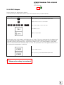
6.3.3 Connectors on TE 410
SERVICE MANUAL TNC 415B/425
Page 42
Issue: 20.08.95
6.3.4 Pin Layout: TE 410
X1 Connection of the Soft Keys of the
Logic Unit
flange socket with female insert (9-pin)
Pin No.
Assignment
1
SL0
2
SL1
3
SL2
4
SL3
5
do not assign
6
RL15
7
RL14
8
RL13
9
RL12
X2 Connection to the Logic Unit
flange socket with male insert (37-pin)
Pin No.
Assignment
1
RL0
2
RL1
3
RL2
4
RL3
5
RL4
6
RL5
7
RL6
8
RL7
9
RL8
10
RL9
11
RL10
12
RL11
13
RL12
14
RL13
15
RL14
16
RL15
17
RL16
18
RL17
19
RL18
20
SL0
21
SL1
22
SL2
23
SL3
24
SL4
25
SL5
26
SL6
27
SL7
28
RL19
29
RL20
30
do not assign
31
RL21
32
RL22
33
RL23
34
spindle override (wiper)
35
feed override (wiper)
36
+ 5V
37
0V
X3 Connection to the Logic Unit
flange socket with male insert (37-pin)
Pin No.
Assignment
1
I 128 unlock shelter door 3)
2
I 129 coolant ON/OFF
3
I 130 spindle OFF
4
I 131 NC OFF
5
I 132 NC ON
6
I 133 axis address key X- 1) X+ 2)
7
I 134 axis address key Y- 1) Z- 2)
8
I 135 axis address key Z- 1) Y- 2)
9
I 136 axis address key Z+ 1) Y+ 2)
10
I 137 axis address key Y+ 1) Z+ 2)
11
I 138 axis address key X+ 1) X- 2)
12
I 139 axis address key IV+
13
I 140 axis address key IV14
I 141 rapid traverse
15
I 142 spindle ON
16
do not assign
17
do not assign
18
do not assign
19
I 146 axis address key V+
20
I 147 axis address key V21
I 148 spindle probing operation
22
do not assign
23
do not assign
24
do not assign
25
do not assign
26
do not assign
27
do not assign
28
do not assign
29
do not assign
30
do not assign
31
do not assign
32
do not assign
33
do not assign
34
do not assign
35
do not assign
36
+ 24V - PLC
37
+ 24V - PLC
= key matrix
1) = TE versions 01/03
2) = TE versions 02/04
3) = TE Id.Nos. 264 105 05/06
SERVICE MANUAL TNC 415B/425
Page 43
Issue: 20.08.95
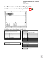
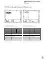
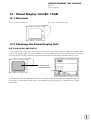
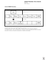
6.4 Connectors on the Visual Display Units
6.4.1 Connectors on the Visual Display Unit BC 110
6.4.2 Pin Layout: Visual Display Unit BC 110
X1 Connection to the Logic Unit
flange socket with male insert (15-pin)
Pin No.
7
9
10
11
14
15
Assignment
R analogue
V-SYNC
H-SYNC
0V
G analogue
B analogue
X3 Power Connection
Euro connector
X2 Connection of the soft keys to the
Keyboard Unit
flange socket with male insert (9-pin)
Pin No.
Assignment
1
SL0
2
SL1
3
SL2
4
SL3
6
RL15
7
RL14
8
RL13
9
RL12
X4 DC Connection for Integral Fan
terminal strip (2-pin)
Pin No.
Assignment
1
+24V
2
0V
= key matrix
SERVICE MANUAL TNC 415B/425
Page 44
Issue: 20.08.95
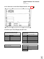
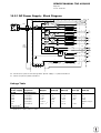
6.4.3. Connectors on the Visual Display Unit BC 110 B
6.4.4 Pin Layout: Visual Display Unit BC 110 B
X1 Connection to the Logic Unit
flange socket with male insert (15-pin)
Pin No.
7
9
10
11
14
15
Assignment
R analogue
V-SYNC
H-SYNC
0V
G analogue
B analogue
X3 Power Connection
terminal strip (3-pin)
Assignment as labelled
X2 Connection of the Soft Keys to the
Keyboard Unit
flange socket with male insert (9-pin)
Pin No.
Assignment
1
SL0
2
SL1
3
SL2
4
SL3
6
RL15
7
RL14
8
RL13
9
RL12
X4 Test Output
terminal strip (2-pin)
Pin No.
Assignment
+
6V
0V
= key matrix
PLC Graphics Board
Machine operating panel
PLCInterface
PL/PA
63 inputs
Processor Board
Handwheel RS-232
RS-422
Handwheel
interface
RS-422interface
RS-232interface
DUART
31 outputs
A/D converter
8-bit
CLP Board
3D touch probe
Shared memory
SRAM
EPROM
TIMER
3D touch
probe
meas. touch
probe
3 * analogue
X
Encoder
inputs
5 * analogue
1 *square
(192K*16)
Z
IV
V
VI
TIMER
TIMER
SRAM
SRAM
EPROM
EPROM
CPU
communication
processor
68020
32 bits/16MHz
CPU
geometry
processor
68020
32 bits/16MHz
SRAM
Boot-EPROM
CPU
CLP processor
68020
32 bits/16MHz
X
Y
6*nom.
value output
Z
16 bits
IV
V
VI
SERVICE MANUAL TNC 415B/425
Video RAM
Y
Page 45
Issue: 20.08.95
Keyboard
interface
Color
pallet
Interface
Software module
Videocontroller
Color/analogue
screen
Interface
ARBITER
feed rate, temp.,
battery
monitoring
Keyboard
Measuring touch probe
7. Block Diagrams
TNC 415 Block Diagram
SERVICE MANUAL TNC 415B/425
Page 46
Issue: 20.08.95
SERVICE MANUAL TNC 415B/425
Page 47
Issue: 20.08.95
8. Board Description
LE 415B/425
PROCESSOR BOARD
- Interfaces
V.24/RS-232-C data interface
V.11/RS-422 data interface
HR 130/330 handwheel
- Monitoring function
EMERGENCY STOP
- Storage
Operating program (NC software)
PLC programs
Machine parameters
Compensation value lists
NC program (customized programs)
CLP BOARD
- Interfaces
Encoder inputs
3D touch probe
- Monitoring functions
Encoder inputs
Axis position
Program memory
Data processing
EMERGENCY STOP
PLC GRAPHICS BOARD
- Interfaces
57 PLC inputs
31 PLC outputs
Visual display unit
Keyboard unit
Machine operating panel
PLC I/O boards
- Monitoring functions
Temperature
Voltages
Buffer battery
SERVICE MANUAL TNC 415B/425
Page 48
Issue: 20.08.95
SERVICE MANUAL TNC 415B/425
Page 49
Issue: 20.08.95
SERVICE MANUAL TNC 415B/425
Page 50
Issue: 20.08.95
NOTES
SERVICE MANUAL TNC 415B/425
Page 51
Issue: 20.08.95
10. Power Supply
10.1 External Power Supply Requirements
The voltages must correspond to the following definitions:
Assembly
LE
Power Supply
NC
Voltage Range
DC Mean Value
lower limit
24V - (VDE 0551)
Max. Current
Consumption
LE 415/425: 1.5A
Power Consumption
1.8A
if half of the
inputs/outputs are
active simultaneously
21A
if half of the
inputs/outputs are
active simultaneously
approx. 100mA
approx. 6W
if approx. 1/3 of the
inputs/outputs are active
simultaneously
approx. 25W
if approx. 1/3 of the
inputs/outputs are active
simultaneously
approx. 2.9W
LE 415/425: approx. 36W
20.4V ...
upper limit
PLC
24V - (VDE 0550)
31V ...
1)
PL 400
PL 410
PA 110
1)
Voltages up to 36V ... are permissible with t < 100ms.
10.1.1 NC Power Supply
U
24V
1.5Vpp
The NC part of the LE must not be connected to the control
voltage of the machine tool. It requires its own external
power supply generated separately according to the German
standard VDE 0551.
24V DC voltage with a permissible AC component
(ripple voltage) of 1.5Vpp (recommended filtering capacitor
10 000µF/40V - ).
t
10.1.2 PLC Power Supply
The PLC part (PLC inputs and outputs) of the LE, PL and PA is operated with a control voltage of 24V- of the
machine tool (generated according to VDE 0550).
The installation and connection of the measuring resistors and the analogue inputs (PL 410, PA 110) must be
safe from contact according to VDE 0160 (section 5.5.1).
If this cannot be ensured, PLC and PL 410 (PA 110) have to be powered according to VDE 0551.
Superimposed AC voltage components arising from a non-controlled three-phase bridge connection with a
ripple factor of 5% (see German standard DIN 40110/10.75, section 1.2) are permissible. Thus the highest
absolute value for the upper voltage limit is 32.6V; the smallest value for the lower voltage limit is 18.5V.
The 0V line of the PLC power supply must be connected to
the central signal ground (line ∅ ≥ 6mm2) of the machine tool.
U
32.6 V
The ground connector on the PL410 housing must be
31 V
connected to the protective ground (line ∅ ≥ 6mm2). To avoid
ground loops the measuring voltage at the analogue inputs
must not be grounded.
20.4 V
18.5 V
t
SERVICE MANUAL TNC 415B/425
Page 52
Issue: 20.08.95
10.1.3 Power Supply of the Visual Display Units
BC 110
BC 110B
X1 = connection of logic unit
X2 = keyboard connection (for soft keys)
X1 = connection of logic unit
X2 = keyboard connection (for soft keys)
X3 = Line connection
X3 = Line connection
Line voltage
110 V~
220 V~
Line voltage
110 V~
220 V~
Voltage range
85 ... 132 V~
170 ... 264 V~
Voltage range
85 ... 132 V~
170 ... 264 V~
Line fuse
F 3.15 A
F 3.15 A
Line fuse
T 2.0 A
T 2.0 A
Frequency
49 ... 61 Hz
Power consumption
60 W
X4 = DC connection for fan
Pin designation
Assignment
Frequency
Power consumption
49 ... 61 Hz
60 W
X4 = Voltage output for testing
Pin designation
Assignment
1
+ 24 V
+
6V
2
0V
-
0V
Note:
The fan of BC 110B is supplied internally
with + 24V.
SERVICE MANUAL TNC 415B/425
Page 53
Issue: 20.08.95
10.2 Power Supply of the NC
The power supply line of the NC is connected to the terminals of X31.
X31 NC power supply
Pin No.
Assignment
1
+ 24 V
2
0V
The different voltages for the LE are transformed from the voltage fed (+24V) in the POWER SUPPLY
assembly (see block diagrams in section 10.2.1).
The input and output voltages are displayed by LEDs. The states of the individual voltages are only displayed
approximately by the LEDs. The exact values must be measured; the measured values must correspond to
the table in section 10.2.1.
SERVICE MANUAL TNC 415B/425
Page 54
Issue: 20.08.95
10.2.1 NC Power Supply: Block Diagram
X2
X1
wh/bk 11
LH4
VDE 0551
+12V
X31
+
+24V
wh/bl
F 2.5A
2
F 4.0A
-
0V
LH5
24V
BE
+24V
1
12
wh/br 10
LH2
BE
12V
LH6
LH7
bk
LH8
-15V
-15V
9
9
gn
6
6
br
3
3
re
4
4
re/bl
1
1
LH13
LH15
-12V
+15V
gr
LH14
LH16
LH18
+15V
LH17
LH20
+12V
LH19
LH22
+5V
LH21
power
supply,
housing
+5V *1
LH1
0V *1
re/bk 12
12
br/gn 7
7
bk
5
5
pi
8
8
LH3
RES
LH12
LH11
LH24
LH23
1k
3
4
bk
re
LH10
power supply board
LH9
battery 3 x 1.5 V
X2: connector (12-pin) of connecting cable "power supply <-> processor board"
X1: socket (12-pin) on processor board
Voltage Table
Test point on Reference point
power supply on power
board
supply board
LH22
LH24 (0V)
LH20
LH24 (0V)
LH18
LH24 (0V)
LH14
LH24 (0V)
LH10
LH24 (0V)
LH1
LH3 (0V*1)
LH12 (reset) 2)
1) potential-free voltage
2) reset ULmax = 0.4 V, UHmin = 3.9 V
Output
UNOM [V]
UMIN [V]
UMAX [V]
INOM [A]
+ 5V (UP)
+ 12V
+ 15V
- 15V
+ UBATT
+ 5V * 1 1)
+ 5.05
+ 12
+ 15.0
- 15.0
+ 4.5
+5
+ 5.00
+ 11.4
+ 14.4
- 14.4
+ 3.9
+ 4.75
+ 5.10
+ 12.6
+ 15.6
- 15.6
+ 5.25
2.5
0.1
0.15
0.08
approx. 20 µA
0.3
SERVICE MANUAL TNC 415B/425
Page 55
Issue: 20.08.95
10.3 Checking the Power Supply Unit
Two low-voltage fuses are located on the POWER SUPPLY assembly. The fuse F 2.5A protects the output
voltage of +24V BE (not required for TNC 415B/425), and the fuse F 4.0A protects the remaining voltages (see
block diagram in section 10.2.1). If an error occurs in the power supply (all voltages missing), first check the
+24V at the supply line (2-pin terminal strip X31) and then the low-voltage fuse F 4.0A.
The voltages can be measured directly on the power supply board, the processor board and the CLP board
(sections 10.3.1 and 10.3.2).
The values and their tolerances can be seen from the corresponding tables. If the measured values deviate
distinctly from the values in the table, the power supply assembly is defective.
*
Observe the safety instructions!
The power supply unit does not work without load.
(Basic load is required)
SERVICE MANUAL TNC 415B/425
Page 56
Issue: 20.08.95
10.3.1 Test Points on the Power Supply Board
Voltage Table
Test point on Reference point
power supply on power
board
supply board
LH22
LH24 (0V)
LH20
LH24 (0V)
LH18
LH24 (0V)
LH14
LH24 (0V)
LH10
LH24 (0V)
LH1
LH3 (0V*1)
LH12 (reset) 2)
1) potential-free voltage
2) reset ULmax = 0.4 V, UHmin = 3.9 V
Output
UNOM [V]
UMIN [V]
UMAX [V]
INOM [A]
+ 5V (UP)
+ 12V
+ 15V
- 15V
+ UBATT
+ 5V * 1 1)
+ 5.05
+ 12
+ 15.0
- 15.0
+ 4.5
+5
+ 5.00
+ 11.4
+ 14.4
- 14.4
+ 3.9
+ 4.75
+ 5.10
+ 12.6
+ 15.6
- 15.6
+ 5.25
2.5
0.1
0.15
0.08
approx. 20 µA
0.3
SERVICE MANUAL TNC 415B/425
Page 57
Issue: 20.08.95
10.3.2 Test Points on the Boards
Processor board TNC 415B/425 Id.No. 268 553 --
SERVICE MANUAL TNC 415B/425
Page 58
Issue: 20.08.95
CLP board TNC 425 Id.No. 265 401 -- and Id.No. 268 927 --
SERVICE MANUAL TNC 415B/425
Page 58.1
Issue: 20.08.95
CLP Board TNC 415B/425 Id.No. 275 705 -- and Id.No. 275 911 --
SERVICE MANUAL TNC 415B/425
Page 59
Issue: 20.08.95
10.4 Power Supply of the PLC
The power supply line for the internal PLC of LE 415B/425 is connected to the terminal strip X44.
X44 PLC power supply of LE 415B/425
Terminal strip (pluggable) 3-pin
Pin No.
Assignment
1
+ 24 V_A, can be switched off
via EMERGENCY STOP
2
+ 24 V , cannot be switched off
via EMERGENCY STOP
3
0V
Fuses:
F1: 3.15A (+ 24V_A, can be switched off)
F2: 1.0A (+ 24V, cannot be switched off)
The PLC power supply of PL 400, PL 405, PL 410 or PA 110 is connected to the following terminal strips:
Power supply of PA 110
Pin No.
Assignment
1
+ 24 V - can be switched off via
EMERGENCY STOP
2
0V
Power supply of PL 400
Terminal
Assignment
X13
+ 24 V can be switched off via
EMERGENCY STOP
X12
0V
X3, pin 12
+ 24V_A cannot be switched off
via EMERGENCY STOP
Power supply of PL 405 / 410
X9, X10, X11, X12, X13, X14
Power supply of PL
Terminal
Assignment
X9
0V
X10
+ 24V- logic unit and "control ready for operation"
X11 1)
X12 1)
+ 24V- logic unit for outputs
O32 - O39
O64 - O71
+ 24V- logic unit for outputs
O40 - O47
O72 - O79
X13
+ 24V- logic unit for outputs
O48 - O55
O80 - O87
X14
+ 24V- logic unit for outputs
O56 - O62
O88 - O94
Fuse:
1)
- F2: T1A (+ 24V- supply for logic unit)
not with PL 405
1.PL
2.PL
SERVICE MANUAL TNC 415B/425
Page 60
Issue: 20.08.95
10.4.1 PLC Power Supply: Block Diagram
machine
operating
panel
X46
1
.
.
.
33
34
35
PLC board version
03
36
37
PLC input
X42
PLC board versions
1
01/02
.
.
34
35
for testing
only
36
37
PLC output
F 3.15A
X41
+24V_A
F 1A
+24V
1
to internal
PLC
.
.
33
34
for testing
only
+24V
0V
36
37
10
3
X44
24V_A
1
24V
0V
2
3
11
wh
wh/bk
can be switched off
via ext. EMERG. STOP
VDE 0550
0V
35
12
bk
2
1
B
1
0
X12
X3/12
X13
X9 X10 X11 X12 X13 X14
1)
1)
1)
X6/1
X6/2
1)
not with
PL 405
PL 400
(option)
1)
PA 110
24V or 24V_A
PL 405/410
(option)
(option)
can be powered with 24V or 24V_A
X44 Pin 1, +24V_A (PLC can be switched off): power supply for the PLC outputs O0 - O23.
X44 Pin 2, +24V (PLC cannot be switched off): power supply for the PLC outputs O24 - O30 and output
"control ready for operation"; power supply for PLC graphics
board.
SERVICE MANUAL TNC 415B/425
Page 61
Issue: 20.08.95
10.4.2 Test Points on the PLC Graphics Boar
SERVICE MANUAL TNC 415B/425
Page 61.1
Issue: 20.08.95
10.5 Buffer Battery
The buffer battery is the voltage source for the program
memory when the machine tool is switched off.
If the error message
EXCHANGE BUFFER BATTERY
is generated, the batteries must be exchanged within
one week.
The buffer batteries are located behind a screw fitting in the
power supply of the LE. To exchange the batteries, open
the LE by undoing the snaps.
In order to protect the program memory of TNC 415B/425,
a capacitor (on the processor board) is used in addition to
the batteries. Thus, the line voltage may be switched off
during battery exchange.
Without the batteries the capacitor is capable of maintaining
the memory contents for about one day.
*
The capacitor is only being charged when the TNC
is switched on.
3 AA-size batteries
leak-proof
IEC designation "LR6"
SERVICE MANUAL TNC 415B/425
Page 62
Issue: 20.08.95
11.
Keyboard Unit TE 400/410
11.1 Overview
TE 400 Id.No. 250 517 ..
Version 01
Version 02
.
.
Version 03
APPR
DEP
CR
CHF
.
.
RND
CT
L
CC
C
(remaining keys as version 01)
TE 410 Id.No. 258 645 ..
Version 01
(without protective frame)
IV+
Z´-
Y+
X´+
Y-
Version 03
(with protective frame)
V+
IV+
X´-
Z´+
Z´-
X´+
Y-
V-
IV-
Y+
V+
X´-
Z´+
IV-
V-
Version 02
Version 04
(without protective frame)) (with protective frame)
IV+
Y´-
Z+
X´Z-
V+
IV+
X´+
Y´+
Y´-
X´Z-
V-
IV-
CR
.
.
RND
CT
CHF
CC
L
C
(remaining keys as version 01)
V+
X´+
Y´+
Version 05 (remaining keys as version 03)
Version 06 (remaining keys as version 04)
APPR
DEP
Z+
IV-
V-
SERVICE MANUAL TNC 415B/425
Page 63
Issue: 20.08.95
TE 410 Id.No. 264 105 ..
Version 01
IV+
Z´-
Version 02
Y+
X´+
Y-
V+
IV+
X´-
Z´+
Y´-
X´Z-
V-
IV-
CR
.
.
RND
CT
CHF
CC
Y´+
L
C
Version 05 (remaining keys as version 03)
Version 06 (remaining keys as version 04)
T
O
I
V+
X´+
Version 03 (remaining keys as version 01)
Version 04 (remaining keys as version 02)
APPR
DEP
Z+
IV-
V-
SERVICE MANUAL TNC 415B/425
Page 64
Issue: 20.08.95
11.2 Checking the Keyboard Unit
The keyboard unit can be checked fast and reliably with the measuring adapter.
11.2.1 Checking the Key Functions
Proceeding:
*
Observe the safety instructions!
• Switch off the main switch.
• Disconnect the keyboard unit from the LE and connect the measuring adapter (see section 20) to
the keyboard unit.
Now the contacts of the keys can be measured at the measuring adapter with an Ohmmeter.
PGM
NR
is pressed at the TNC operating panel, approx. 1 Ω can be measured at the adapter between
If e.g.
PIN 8 and PIN 24 (see key matrix, section 11.2.3 and 11.2.4); consider the resistance of the testing wires.
11.2.2 Measuring Setup for Checking the Functions of the NC-Keys
TE
BC 110/B
X1 (9-pin)
X2 (37-pin)
test adapter
Ω
multimeter
SERVICE MANUAL TNC 415B/425
Page 65
Issue: 20.08.95
11.2.3
Key Matrix of the Keyboard Unit
X2 Pin
1
2
3
4
5
6
7
8
9
17
18
19
28
29
31
32
20
21
22
23
24
25
26
27
Key
RL0
1
2
3
4
5
6
7
8
16
17
18
19
20
21
22
SL0
1
2
3
4
5
6
7
!
X
X
X
X
S
X
0/
0
X
X
X
X
&
X
X
X
*
X
(
X
)
X
X
X
X
X
X
X
X
X
X
X
"
X
Q
X
X
X
E
X
X
X
R
X
T
X
X
X
Y
X
U
X
X
X
X
P
X
X
W
O
X
X
X
X
X
X
SERVICE MANUAL TNC 415B/425
Page 66
Issue: 20.08.95
X2 Pin
1
2
3
4
5
6
7
8
9
17
18
19
28
29
31
32
20
21
22
23
24
25
26
27
Key
RL0
1
2
3
4
5
6
7
8
16
17
18
19
20
21
22
SL0
1
2
3
4
5
6
7
X
X
X
RET
CTRL
X
A
X
X
X
X
S
X
D
X
X
X
F
X
G
X
X
X
H
X
J
X
X
X
K
X
L
X
;
X
X
X
X
X
:
X
SPACE
X
Z
X
X
X
X
X
X
C
X
X
X
V
X
B
X
X
X
N
X
M
X
,
X
X
X
X
X
SERVICE MANUAL TNC 415B/425
Page 67
Issue: 20.08.95
X2 Pin
1
2
3
4
5
6
7
8
9
17
18
19
28
29
31
32
20
21
22
23
24
25
26
27
Key
RL0
1
2
3
4
5
6
7
8
16
17
18
19
20
21
22
SL0
1
2
3
4
5
6
7
.
X
X
?
X
/
X
X
X
X
SPACE
PGM
NAME
X
X
CL
PGM
X
X
PGM
CALL
X
X
X
X
EXT
X
X
X
X
MOD
X
X
.
X
X
X
X
X
X
X
X
X
X
X
X
X
X
APPR
DEP
X
X
X
X
X
X
X
SERVICE MANUAL TNC 415B/425
Page 68
Issue: 20.08.95
X2 Pin
1
2
3
4
5
6
7
8
9
17
18
19
28
29
31
32
20
21
22
23
24
25
26
27
Key
RL0
1
2
3
4
5
6
7
8
16
17
18
19
20
21
22
SL0
1
2
3
4
5
6
7
CHF
X
L
X
X
CR
X
RND
X
CT
X
X
X
C
X
X
X
X
TOUCH
PROBE
X
CYCL
DEF
X
CYCL
CALL
X
X
LBL
SET
X
X
LBL
CALL
X
STOP
X
X
X
X
TOOL
DEF
X
TOOL
CALL
X
RL
X
R +R
X
X
X
X
X
X
X
7
X
X
8
X
X
X
X
X
Y
4
X
X
CC
9
X
X
X
X
X
SERVICE MANUAL TNC 415B/425
Page 69
Issue: 20.08.95
X2 Pin
1
2
3
4
5
6
7
8
9
17
18
19
28
29
31
32
20
21
22
23
24
25
26
27
Key
RL0
1
2
3
4
5
6
7
8
16
17
18
19
20
21
22
SL0
1
2
3
4
5
6
7
5
6
X
X
X
X
Z
X
1
X
2
3
X
X
X
X
X
X
IV
X
0
X
X
.
X
X
X
X
X
+/
V
X
X
X
X
X
Q
X
X
X
X
CE
DEL
X
P
X
X
X
X
X
NO
ENT
X
X
ENT
X
END
X
X
X
X
X
X
GOTO
X
X
X
X
X
X
X
X
SERVICE MANUAL TNC 415B/425
Page 70
Issue: 20.08.95
11.2.4 Key Matrix of the VDU Keys
X1 Pin 1)
4b
3b
2b
1b
1a
2a
3a
4a
X2 Pin 1)
13
14
15
16
20
21
22
23
Key 2)
RL12
RL13
RL14
RL15
SL0
SL1
SL2
SL3
X
X
SK1
X
X
X
X
SK4
X
X
SK5
X
X
SK6
SK7
X
X
SK2
SK3
X
X
X
X
X
SK8
X
X
X
X
X
1)
2)
X
X
connector on keyboard unit
VDU key
X1: connector for flat cable VDU Ö keyboard unit (plug-type connector)
X2: connector for cable keyboard unit Ö logic unit (D-SUB, 37-pin)
SK = soft key ( SK1...SK8 from left to right)
SERVICE MANUAL TNC 415B/425
Page 71
Issue: 20.08.95
11.2.5 Checking the Potentiometers
Proceeding:
*
Observe the safety instructions!
Connect the measuring adapter to X45 of the logic unit. Now the wiper voltages of the potentiometers
can be measured with a multimeter.
Potentiometer
override F%
spindle S%
PIN
37 = 0V / 35 = + pot.
37 = 0V / 34 = + pot.
Voltage
(0 to approx. 4.95)V
(0 to approx. 4.95)V
11.2.6 Measuring Setup for Checking the Potentiometers
TE
logic unit
X45
test
measuring
adapter
adapter
0.15
multimeter
SERVICE MANUAL TNC 415B/425
Page 72
Issue: 20.08.95
11.2.7 Machine Operating Panel of TE 410
The PLC inputs of the machine operating panel of TE 410 (I128 - I148) can be tested at the flange socket X3
(37-pin) on the keyboard unit TE 410 or at the flange socket X46 (connection of machine control panel) of the
TNC 415B/425.
For this purpose the TABLE function (see section 19.4) in the PLC mode is helpful as well.
KEY
of version
Flange socket X3 on
KEYBOARD UNIT
PLC
KEY
of version
1)
01/03
02/04
PIN
PIN
Input
IV+
IV+
12
36.37
I139
Z´-
Y´-
8
36.37
I135
Y+
Z+
10
36.37
I117
V+
V+
19
36.37
X´+
X´-
11
05/06
Flange socket X3 on
KEYBOARD UNIT
PLC
PIN
PIN
Input
3
36.37
I130
15
36.37
I142
21
36.37
I148
I146
1
36.37
I128
36.37
I138
2
36.37
I129
14
36.37
I141
NC
0
NC
0
4
36.37
I131
NC
I
NC
I
5
36.37
I132
O
O
I
I
T
T
X´-
X´+
6
36.37
I133
Y-
Z-
7
36.37
I134
Z´+
Y´+
9
36.37
I136
1)
IV-
IV-
13
36.37
I140
pin 36/37 = + 24V_PLC
V-
V-
20
36.37
I147
remaining versions
SERVICE MANUAL TNC 415B/425
Page 73
Issue: 20.08.95
12. Visual Display Unit BC 110/B
12.1 Overview
BC 110 Id.No. 254 740 01
BC 110 B Id.No. 260 520 01
12.2 Checking the Visual Display Unit
BC 110 B, Id.No. 260 520 01
If the screen remains dark when the machine is switched on, first check the power supply (line voltage) of the
VDU. If the voltage supply is functioning properly, a square highlighted filed can be generated on the screen of
the VDU (which must be switched on) by pressing the external test button on the back side of the unit.
highlighted field
external test button
If the VDU generates this highlighted field, the PLC graphics board in the logic unit is probably defective.
If however, the VDU remains dark after the test button was pressed, the VDU is defective and must be
exchanged.
SERVICE MANUAL TNC 415B/425
Page 74
Issue: 20.08.95
BC 110, Id.No. 254 740 01
If the screen remains dark when the machine is switched on, first check the power supply (line voltage) of the
VDU. The control signals for the screen can only be checked with an oscilloscope.
The following diagrams were generated with the VISUAL DISPLAY UNIT connected. Depending on machine
parameters and image depicted, the colour signals R-analog, Y-analog and B-analog may differ from those on
page 75.
X43 Visual Display Unit (BC 110)
flange socket with female insert (15-pin)
Pin No.
1, 8, 11
2 to 6, 12, 13
7
9
10
14
15
Assignment
GND
do not assign
R signal
V SYNC
H SYNC
Y signal
B signal
Diagrams
V-SYNC PIN 9
H-SYNC PIN 10
2V/DIV
2V/DIV
10 ms/DIV
20 µs/DIV
SERVICE MANUAL TNC 415B/425
Page 75
Issue: 20.08.95
R-analog PIN 7 1)
Y-analog PIN 14 1)
0,2V/DIV
0,2V/DIV
5 ms/DIV
5 ms/DIV
B-analog PIN 15 1)
0,2V/DIV
5 ms/DIV
1
When measuring the colour signals directly at the output of the logic unit (without the VISUAL DISPLAY
UNIT connected), the amplitudes are twice as large.
SERVICE MANUAL TNC 415B/425
Page 76
Issue: 20.08.95
13. Encoders
13.1 Error Messages for Axes with Analogue
Speed Controller
ENCODER <AXIS> DEFECTIVE YA
A = signal amplitude error
ENCODER <AXIS> DEFECTIVE YB
B = signal frequency error
ENCODER <AXIS> DEFECTIVE YC
C = error with distance-coded scales
Y = CPU number
1 = main processor
2 = geometry processor
3 = CLP processor
13.1.1 Error Causes
• Glass scale contaminated or damaged
• Scanning head contaminated or defective
• Cable damaged
• Encoder input of the logic unit (LE) defective
13.1.2 Error Location
In order to determine whether the encoder or the encoder input of the logic unit is defective, the encoders
can be switched at the logic unit. For this purpose the corresponding machine parameters must be altered
as well:
Function
Allocation of the axes
to the encoder inputs
Entry Value
0 = X1
1 = X2
2 = X3
3 = X4
4 = X5
5 = X61)
1) X6 may be used for a machine axis, if no oriented spindle stop is required.
X
Y
Z
IV
V
MP
110.0
110.1
110.2
110.3
110.4
SERVICE MANUAL TNC 415B/425
Page 77
Issue: 20.08.95
Flow-Chart for Error Location
ENCODER X DEFECTIVE 3B
(Example)
switch off power
switch encoder of X axis
and e.g. encoder of Y axis
at the logic unit
switch on power
if the message
POWER INTERRUPTED
is generated, enter code number
95148 to call the active parameter
list and switch the entry values
of MP110.0 and 110.1
Does the error message
switch from X to Y?
NO
YES
Defect is located in the position
encoder input of the control
*
Observe the safety instructions!
Defect is located in the position
encoder or in the encoder cable
SERVICE MANUAL TNC 415B/425
Page 78
Issue: 20.08.95
13.2 Error Messages for Axes with Integral Digital
Speed Controller
With the integral digital speed controller there are two encoder inputs for each axis:
Encoder inputs for the actual position:
encoder 1:
input X1
encoder 2:
input X2
encoder 3:
input X3
encoder 4:
input X4
encoder 5:
input X5
encoder S:
input X6
Encoder inputs for the actual speed:
encoder 1:
input X15
encoder 2:
input X16
encoder 3:
input X17
encoder 4:
input X18
encoder 5:
input X19
Therefore, there are two groups of error messages:
Monitoring of actual position capture (X1, X2, X3, X4, X5, X6)
ENCODER <AXIS> DEFECTIVE YA
A = signal amplitude error, position encoder
Y = CPU number
ENCODER <AXIS> DEFECTIVE YB
B = signal frequency error, position encoder
1 = main processor
2 = geometry processor
3 = CLP processor
ENCODER <AXIS> DEFECTIVE YC
C = error with distance-coded scales, position encoder
Monitoring of actual speed capture (X15, X16, X17, X18, X19)
ENCODER <AXIS>` DEFECTIVE YA
A = signal amplitude error, speed encoder
Y = CPU number
ENCODER <AXIS>` DEFECTIVE YB
B = signal frequency error, speed encoder
1 = main processor
2 = geometry processor
3 = CLP processor
ENCODER <AXIS>` DEFECTIVE YC
C = error with distance-coded scales (speed encoder)
13.2.1 Error Causes
• Glass scale contaminated or damaged
• Scanning head contaminated or defective
• Cable damaged
• Encoder input of the logic unit (LE) defective
13.2.2 Error Location
In order to determine whether the one of the encoders of an axis or one of the encoder inputs on the logic
unit is defective, the encoders can be switched at the logic unit. For this purpose the corresponding machine
parameters must be altered as well (always change both parameters!):
Function
Allocation of the axes
to the encoder inputs
1)
Entry value
0 = X1 (pos.) / X15 (speed)
1 = X2 (pos.) / X16 (speed)
2 = X3 (pos.) / X17 (speed)
3 = X4 (pos.) / X18 (speed)
4 = X5 (pos.) / X19 (speed)
5 = X61) (pos.)
X6 can be used for a machine axis, if no oriented spindle stop is required.
X
Y
Z
IV
V
MP
110.0
110.1
110.2
110.3
110.4
SERVICE MANUAL TNC 415B/425
Page 79
Issue: 20.08.95
Flow-Chart for Error Location
ENCODER X` DEFECTIVE 3B
(Example)
switch off power
switch encoder of X axis
and e.g. encoder of Y axis
at the logic unit
NOTE: always switch both
encoders: X1 + X2; X15 + X16!
switch on power
if the message
POWER INTERRUPTED
is generated, enter code number
95148 to call the active parameter
list and switch the entry values
of MP110.0 and 110.1
Does the error message
switch from X to Y?
NO
YES
Defect is located in the position
encoder input of the control
*
Observe the safety instructions!
Defect is located in the position
encoder or in the encoder cable
SERVICE MANUAL TNC 415B/425
Page 80
Issue: 20.08.95
13.3 Electrical Inspection of an Encoder
In order to give a precise statement on the electrical function of an encoder, it must be measured with a
phase angle measuring unit (PWM), an oscilloscope and a leak tester. (see operating instructions of encoder
diagnostic set)
If no phase angle measuring unit is available, the electrical state of the cable, the lamp and the photocells of
an encoder can be checked with an ohmmeter. The following resistances must be measured at the connector
of the encoder:
Possible measurements at an encoder with current interface (7 - 16µA)
• encoder connector housing against machine chassis < 1 Ω (external shield)
• encoder connector housing against PIN 9 (internal shield - external shield) R = ∞
• encoder connector housing against PIN 1 to PIN 8 (external shield - signal lines ) R = ∞
• PIN 9 against PIN 1 to PIN 8 (internal shield - signal line) R = ∞
• pin 1 against pin 2
• pin 2 against pin 1
• pin 5 against pin 6
• pin 6 against pin 5
• pin 7 against pin 8
• pin 8 against pin 7
0°
0°
90°
90°
RP1)
RP1)
(switch poles of ohmmeter)
The measured values should
approximately equal.
(switch poles of ohmmeter)
(switch poles of ohmmeter)
(approx. 5 - 30 Ω)
• pin 3 against pin 42)
1)
If encoders with selectable reference mark are used, different resistance values can be measured
(or no resistance), depending on the type of activation.
2) The encoder check (pin 3 against pin 4) can only be carried out, if the encoder light unit is a lamp.
If the encoder features an amplifier section, the light unit cannot be checked at all. With encoders
with infrared diodes, a resistance in the conducting direction can be measured between pin 3 (+)
and pin 4 (-).
Basic Circuit Diagram with Sinusoidal Signals (7 - 16µA)
gn
gn 1
0°
ye 2
ye
bl
90°
external shield
re
gr
RI
br
wh
0° La +
wh 4
La bl 5
re 6
pi
R1
br 3
0° +
90° +
90° -
gr 7
RI +
pi 8
wh/br 9
RI internal shield
Encoders with square-wave signals can only be tested with a phase angle measuring unit (PWM).
SERVICE MANUAL TNC 415B/425
Page 81
Issue: 20.08.95
14. Electronic Handwheels
14.1 Handwheel HR 130/330
HR 130
HR 130.001
Id.No. 254 040 -Id.No. 249 371 --
HR 330
Id.No. 251 534 --
Adapter cable for HR 330
Id.No. 249 889 --
pin
1
2
3
4
5
6
color
bl
bl
gn
ye
bn
wh
signal
EMG.
STOP
RxD
DTR
+12V
0V
pin
2
4
6
8
color
wh
bn
ye
gn
signal
0V
+12V
DTR
RxD
14.1.1 Checking the Handwheel HR 130/330
The serial handwheel HR 130 (without auxiliary keys) and HR 330 (with auxiliary keys) can be checked with an
oscilloscope. The following signals can be measured at the handwheel input X23 of LE 415B/425. The signals
have to correspond to the diagram below.
The supply voltage for the handwheel is fed via the logic unit (X23 pin 2 = 0V, pin 4 = + 12V).
SERVICE MANUAL TNC 415B/425
Page 82
Issue: 20.08.95
14.2 Handwheel HR 332
HR 332 Id.No. 266 064 -Connecting cable Id.No. 272 292 --
Adapter cable Id.No. 274 556 01
(12-pin to 9-pin)
Pin
1
2
3
4
5
6
7
8
9
10
11
12
Pin
The assignment of the handwheel keys depends on the version.
* The number of the permissive buttons and the internal wiring depends
on the version of HR 332.
2
4
6
7
8
Signal
designation
EMERG. STOP
EMERG. STOP
Permissive
button *
Permissive
button *
Permissive
button *
not connected
TxD
RxD
Housing shield
DSR
0V
+ 12V
Signal
designation
0V
+ 12V
DTR
TxD
RxD
14.2.1 Checking the Handwheel HR 332
The serial handwheel HR 332 can be checked with an oscilloscope. The following signals can be measured at
the handwheel input X23 of LE 415B/425. The signals have to correspond to the diagram below.
The supply voltage for the handwheel is fed via the logic unit (X23 pin 2 = 0V, pin 4 = + 12V).
SERVICE MANUAL TNC 415B/425
Page 83
Issue: 20.08.95
14.3 Error Messages
HANDWHEEL ?
- Data transfer (cable) has been interrupted
- Incorrect value entered in MP 7640.
HANDWHEEL DEFECTIVE
The light unit in the electronic handwheel is not emitting enough light, with the result that the signals
in the handwheel become too small. An error signal is sent over the serial interface of the handwheel.
SERVICE MANUAL TNC 415B/425
Page 84
Issue: 20.08.95
15.
3D-Touch Probes
15.1 Overview
15.1.1 Touch Probes with External Interface Electronics (APE)
TS 111
Id.No. 237 400 -Transmission via cable
TS 511
Id.No. 237 402 -Infra-red transmission
APE 110
APE 510
APE 511
SE 510
Id.No. 230 465 -- for TS 111
Id.No. 227 590 -- for TS 511
Id.No. 237 586 -- for TS 511
with additional connector for a
second SE 510
Id.No. 230 473 --
15.1.2 Touch Probe with Integral Interface Electronics (APE)
TS 120
Id.No. 243 614 --
Adapter cable for TS 120 Id.No. 244 891 --
SERVICE MANUAL TNC 415B/425
Page 85
Issue: 20.08.95
15.2 Error Messages
15.2.1 Error Messages in the Probing Mode
TOUCH POINT INACCESSIBLE
- After the start of a probing function, the scanning point was not reached within the measuring range defined
in the machine parameter MP6130.
EXCHANGE TOUCH PROBE BATTERY
- The battery voltage of the touch probe system with infrared transmission is below the minimum value.
STYLUS ALREADY IN CONTACT
- The stylus was already deflected when the probing function was started.
PROBE SYSTEM NOT READY
- The infrared transmission between the "Touch Probe" and the "Transmitter/Receiver Unit" is faulty
(e.g. caused by contamination) or interrupted. The two windows of the touch probe system must be
oriented to the transmitter/receiver unit.
- The battery is dead.
- The TM 110 is not connected.
- An error has been detected at one of the encoders of the TM110 (contamination).
15.2.2 Error Messages during Digitizing of 3D-Contours
WRONG AXIS PROGRAMMED
- The touch probe axis in the scanning cycle RANGE is not identical with the calibrated touch probe axis.
FAULTY RANGE DATA
- A MIN coordinate value in the scanning cycle RANGE is larger than or equal to the corresponding
MAX coordinate value.
- One or more coordinates are beyond the limit switch range of the scanning cycle RANGE.
- No scanning cycle RANGE was defined when calling the scanning cycles MEANDER or CONTOUR
LINES.
MIRRORING NOT PERMITTED
ROTATION NOT PERMITTED
SCALING FACTOR NOT PERMITTED
- Mirroring, rotation or scaling factor were active when the scanning cycles RANGE, MEANDER or
CONTOUR LINES were called.
SERVICE MANUAL TNC 415B/425
Page 86
Issue: 20.08.95
RANGE EXCEEDED
- The range has been exceeded during probing, i.e. a part of the 3D-contour is outside the range.
CYCL PARAMETER INCORRECT
- The programmed travel or the distance between lines or points is negative or larger than 56 535 mm.
(only possible with Q-parameter programming)
TOUCH POINT INACCESSIBLE
- The stylus was deflected before the range was reached during approach.
- In the cycle CONTOUR LINES, the stylus was not deflected within the probing range.
STYLUS ALREADY IN CONTACT
- The stylus is not at rest, although it is not touching the contour.
PLANE WRONGLY DEFINED
- One of the coordinates of the starting point in the cycle CONTOUR LINES is identical with the touch
probe axis.
START POSITION INCORRECT
- The starting point coordinate that is identical with the starting probe-axis is beyond the range.
AXIS DOUBLE PROGRAMMED
- The same axis has been programmed for both starting point coordinates in the cycle CONTOUR LINES.
TIME LIMIT EXCEEDED
- In the scanning cycle CONTOUR LINES the first point of the scanned line was not reached within the
programmed time limit.
STYLUS DEFLECTION EXCEEDS MAX.
- The stylus was deflected by more than the value programmed in the machine parameter MP6330 (TM110).
SERVICE MANUAL TNC 415B/425
Page 87
Issue: 20.08.95
16. Data Interfaces
16.1 Operating Modes of the Data Interfaces
For data transfer the TNC 415B/425 can be switched to the following 6 interface modes:
ME: For connection of the HEIDENHAIN Magnetic Tape Unit ME 101/102 or other peripheral units
(e.g. printer).
*
Data format and protocol adapted to ME!
Protocol:
standard transfer
Data format:
7 data bits, 1 stop bit, even parity
Baud rate:
110 - 2400 Baud
Interface parameter: fixed
Transmission stop:
DC3 (software handshake)
FE 1: For connection of the HEIDENHAIN Floppy Disk Unit FE 401 B (or the Floppy Disk Unit FE 401,
from software 230 626 03) or other peripheral units.
*
Data format and protocol adapted to FE 401/B!
Protocol:
blockwise transfer
Data format:
7 data bits, 1 stop bit, even parity
Baud rate:
110 - 38400 Baud (FE 401B)
9600 Baud (FE 401)
Interface parameter: fixed
Transmission stop:
DC3 (software handshake)
FE 2: For connection of the HEIDENHAIN Floppy Disk Unit FE 401 or other peripheral units.
*
Data format and protocol adapted to FE 401/B!
Protocol:
blockwise transfer
Data format:
7 data bits, 1 stop bit, even parity
Baud rate:
110 - 38400 Baud
9600 Baud (FE 401)
Interface parameter: fixed
Transmission stop:
DC3 (software handshake)
EXT 1:To adapt the transfer of data to external units in standard data format
EXT 2:and for blockwise transfer.
*
Protocol:
standard or blockwise transfer
adaptation from machine parameter MP 5000
Data format:
adaptation from machine parameter MP 5000
Baud rate:
110 - 38400 Baud
Interface parameters : adaptation from machine parameter MP 5000
Transmission stop:
DC3 (software handshake) or RTS (hardware handshake)
selectable as of MP5000
LSV/2: With the LSV/2 protocol several functions (such as file management, remote control and
TNC diagnosis from a PC) can be performed with the appropriate software (TNC REMOTE
or LSV/2 TOOLBOX).
SERVICE MANUAL TNC 415B/425
Page 88
Issue: 20.08.95
16.1.1 Interface Configuration and Allocation of the
Operating Modes
In the operating modes PROGRAMMING AND EDITING and TEST RUN the setup menu for the data
interfaces is called after pressing
MOD
and the soft key
.
On the left half of the screen the RS-232-C interface is configured, on the right half the RS-422-C. On the
lower left of the screen the operating modes PROGRAMMING/EDITING, PROGRAM RUN and TEST RUN can
be allocated to either RS-232-C or RS-422-C. (If the MOD function "RS 232/RS 422 SETUP" is called in the PLC
editor or the MP editor, the editor can be allocated to one of the interfaces.)
On the lower right of the screen the user can define via PRINT or PRINT TEST, whether outputs with FN15
and digitized positions are to be output via one of the interfaces or into a file in the memory of the control.
• RS 232 means:
• RS 422 means:
• FILE means:
Data are output via the data interface RS-232-C.
Data are output via the data interface RS-422-C.
Data are filed in the TNC.
Note:
In the machine parameter MP5000 individual interfaces can be disabled.
SERVICE MANUAL TNC 415B/425
Page 89
Issue: 20.08.95
With the arrow keys
the desired settings
GOTO
(operating mode, baud rate, interface allocation) can be selected and set according to your requirements by
pressing
ENT
.
To exit the MOD function RS 232/RS 422 SETUP, press the soft key
.
16.2 Machine Parameters for the Data Interfaces
In the operating modes ME, FE 1, FE 2 and LSV/2 the interface parameters cannot be changed.
In the operating modes EXT 1 and EXT2 the interface parameters can be set via machine parameter
(starting with MP5000).
The detailed functions of the individual machine parameters please see from the "Technical Manual" or from
the "Description of the Data Interfaces TNC 407/415" (Id.No. 275 931 --).
SERVICE MANUAL TNC 415B/425
Page 90
Issue: 20.08.95
16.3 Error Messages
16.3.1 Error Messages at the TNC in the ME Mode
WRONG OPERATING MODE
The wrong operating mode or no operating mode was selected on the external data medium.
WRONG PROGRAM DATA
Wrong program data have been detected during data transfer. The control attempted three times to read the
data from the magnetic tape before interrupting the process.
DATA MEDIUM MISSING
No cassette has been inserted into the drive.
DATA MEDIUM EMPTY
No programs are stored on the data medium (cassette).
DATA MEDIUM WRITE-PROTECTED
The write-enable plug on the cassette is missing.
PROGRAM INCOMPLETE
Data transfer was interrupted before the program was transferred completely.
EXT. INPUT/OUTPUT NOT READY
The DSR-signal is missing at the TNC.
- ME not connected.
- Defective or wrong transfer cable.
- Wrong interface assignment.
ME: TAPE END
The cassette is full. To continue data transfer, turn over or exchange the cassette.
SERVICE MANUAL TNC 415B/425
Page 91
Issue: 20.08.95
16.3.2 Error Messages at the ME
In the ME the electronics is tested, and the external operating conditions are checked. If an error is
detected, the lamps of the operating mode display start blinking. In the following table the error types
are listed:
{ LED off
LED blinking
Indicator Lamp Error Message
{{{
{{{{
Faulty data during transfer
{{{
{{{{
No cassette inserted
{{
{{{{
Write-enable plug in cassette missing
{{{
{{{{
Wrong operating mode selected
{{
{{{{
Data of magnetic tape faulty
{{
{{{{
Magnetic tape empty
{{{
{{{{
{{
{{{{
{{
{{{{
Errors in ME electronics
{
{{{{
{{
{{{{
{
{{{{
{{{{
End of tape
{
{{{{
Peripheral unit not connected
Data transfer between TNC and ME or peripheral unit
{
{{{{
DEL
was interrupted with
STOP
By pressing
the error messages can be cleared.
SERVICE MANUAL TNC 415B/425
Page 92
Issue: 20.08.95
16.3.3 Error Messages at the FE in the ME-Mode
In the ME-mode, errors are displayed by blinking indicator lamps (LEDs).
{ LED off
z LED on
LED blinking
Indicator Lamp Error Message
{{{z
{{{
{{{
{{{
{{z
{{{
{{
{{{
z{z
{{{{
{zz
{{{{
{{z
{{z{
{z
{{{{
{{
{{z{
{{z
z{{{
{{zz
{{{
{{{z
{z{
{{z
{{{
{{{
{z{
{z{z
{{{
{{z
{{z{
{{
{{z{
{{{
{{z{
{{z
{{{{
{{z
{{{{
Disk missing or error in the ME electronics
Disk cannot be formatted, as it is currently being used
Disk missing or not formatted
Disk cannot be copied, as a read/write process is active
External unit not ready or not connected
Disk missing or not formatted
Disk missing or not formatted or no program available
Program cannot be output, as a transfer is active via the TNC interface
Program cannot be output, as a transfer is active via the PRT interface
External unit not ready or not connected
Disk missing or not formatted
Disk missing or not formatted
Program cannot be output, as a transfer is active via the TNC interface
Program cannot be output, as a transfer is active via the PRT interface
External unit not ready or not connected
Disk missing or error in the ME electronics
Table of contents cannot be output, as a transfer is active via the PRT interface
No interface coupling possible, as a transfer is active via the TNC interface
No interface coupling possible, as a transfer is active via the PRT interface
External unit not ready or not connected
STOP
By pressing
the error messages can be cleared.
SERVICE MANUAL TNC 415B/425
Page 93
Issue: 20.08.95
16.3.4 Error Messages at the TNC in the FE Mode
In this operating mode, the floppy disk unit outputs errors in the following format:
(SOH) ERR: (SP) (SP) (SP) [XXX] (ETB) (BCC)
XXX = error number
The following errors can be displayed on the screen:
Input/Output Errors
ERR: 001 = wrong command code
ERR: 002 = illegal program name
ERR: 003 = faulty data transfer
ERR: 004 = program incomplete
ERR: 005 = receiving buffer overflow
ERR: 006 = function currently disabled
ERR: 007 = data-buffer overflow
Errors during Program Write or Read
ERR: 010 = program not on disk
ERR: 011 = program erase-protected
ERR: 012 = program is being written to
ERR: 013 = program directory is full
ERR: 014 = disk is full
ERR: 015 = text not found
ERR: 016 = program name already exists
ERR: 017 = disk access active
ERR: 018 = program currently being read
Disk / Drive / Controller Errors
ERR: 100 = disk not initialized
ERR: 101 = sector number too large 1)
ERR: 102 = drive not ready 2)
ERR: 103 = disk is write-protected
ERR: 104 = faulty data on disk 1)
ERR: 105 = sector cannot be found1)
ERR: 106 = check sum incorrect 1)
ERR: 107 = disk controller defective 3)
ERR: 108 = DMA defective 3)
ERR: 109 = disk exchanged during program loading
1)
These error messages indicate that the disk is defective; in most cases, they can only be
eliminated by formatting the disk anew.
2)
If this error message comes up while the disk is inserted, the drive is probably defective.
3)
Hardware defect
SERVICE MANUAL TNC 415B/425
Page 94
Issue: 20.08.95
16.3.5 Error Messages during Data Transfer
TRANSFERRED VALUE ERRONEOUS X
X= A
B
C
D
E
F
G
H
K
L
faulty character frame
character overflow
faulty character frame or character overflow
parity error
faulty character frame or parity error
character overflow or parity error
faulty character frame or character overflow or parity error
receiving-buffer overflow
} incorrect ESC sequence (only in ME mode)
TRANSFERRED DATA INCORRECT X
X= A
D
M
N
faulty character frame
parity error
control has received the character for "negative acknowledgement" (NAK)
more than 3 times
control has sent the character for "negative acknowledgement" (NAK) more
than 3 times
BAUD RATE NOT POSSIBLE
If both data interfaces (RS 232 / RS 422) are activated simultaneously, the baud rates of both interfaces
must be the same.
INTERFACE ALREADY ASSIGNED
A data interface cannot be used for two operating modes simultaneously. (e.g. DNC mode and programming
at the same time is not possible with one data interface.)
EXT. IN-/OUTPUT NOT READY
-
DSR signal at the TNC missing
Defective or wrong transfer cable
Wrong interface assignment
PROGRAM INCOMPLETE
Data transfer was interrupted before the program was completely loaded.
SERVICE MANUAL TNC 415B/425
Page 95
Issue: 20.08.95
16.4 Wiring Diagrams of the Data Interfaces
16.4.1 RS-232-C Data Interface with RS-232-C Adapter Block (full wiring)
*
If the pin layout of your peripheral unit differs from the above layout, the HEIDENHAIN connecting
cable may not be used.
16.4.2 RS-232C Data Interface with RS-232C Adapter Block
(simplified wiring)
Example:
*
With this wiring, only transfer stop with DC3 is possible (software handshake).
The RS-232-C data interface has different pin layouts at the logic unit X21 and the RS-232-C adapter block.
SERVICE MANUAL TNC 415B/425
Page 96
Issue: 20.08.95
16.4.3 RS-422 Data Interface
*
The RS-422 data interface has identical pin layouts at the logic unit X22 and at the RS-422
adapter block.
SERVICE MANUAL TNC 415B/425
Page 97
Issue: 20.08.95
17. Data Input and Output
17.1 Data Transfer Menu
In the operating mode PROGRAMMING/EDITING (press
), the data transfer menu is activated by
EXT
pressing
.
On the left half of the screen the memory contents of the TNC is displayed; on the right half the memory
contents of the peripheral unit.
The memory contents of the peripheral unit is only displayed automatically in the interface mode FE1. In all
other operating modes it can be loaded by means of the soft key
and
To switch between the screen halves press the arrow keys
By switching the screen half the direction of data transfer is changed.
.
.
SERVICE MANUAL TNC 415B/425
Page 98
Issue: 20.08.95
Explanation of the soft keys:
The program selected with
or
is read in or out.
All programs are read in or out without confirmation.
All programs are read in or out after confirmation.
The following soft keys may be offered depending on the interface mode:
FE1 mode (external directory is loaded automatically):
All file types are displayed.
Only the files with this extension are displayed.
e.g. (.H = NC program in HEIDENHAIN plain language)
FE2 / EXT1 / EXT2 mode:
Only the files with this extension are displayed.
e.g. (.H = NC program in HEIDENHAIN plain language)
The external directory is loaded.
This soft key cancels the split screen display. Afterwards several settings can be made in the
screen half selected before. After pressing the soft key once again, the screen is split again.
SERVICE MANUAL TNC 415B/425
Page 99
Issue: 20.08.95
17.2 Overview of Files for TNC 415B/425
Depending on the subordinate mode (NC, PLC MODE, MP MODE etc.) in which the transfer menu is
activated, only certain file types are offered to be downloaded or output.
The following data may be in the RAM:
NC Memory Management
NC program: HEIDENHAIN language
NC program: ISO
Active tool file
Tool data (table)
Pocket number table
Pallet table
Datum table
Text file (ASCII)
Measuring point table (digitizing)
PLC Memory Management (RAM)
PLC program
Error messages1. language
Error messagesEnglish
Dialogues
1. language
Dialogues
English
ASCII file
Help texts
Data for axis error compensation
Data for axis error compensation
Machine Parameter Mode
Machine parameter lists
Compensation value table
selectable via code number
Extension
(TNC)
.H
.I
TOOL.T
.T
.P
.D
.A
.PNT
Extension
(external)
.H
.D
TOOL.T
.T
TOOL_P.R
.L
.N
.A
.U
.PLC
.ER1
.ERE
.DI1
.DIE
.A
.HLP
.COM
.CMA
.P
.A
.A
.A
.A
.A
.J
.V
.S
.MP
.KOR
.M
.S
Additional information on the files or programs is provided by letters in the status field.
E: The file/program has been selected in the PROGRAMMING mode.
S: The file/program has been selected and activated in the TEST RUN mode.
M: The file/program has been selected and activated in either PROGRAM RUN / FULL SEQUENCE
or in PROGRAM RUN / SINGLE BLOCK.
P: The file/program is protected against erasing and editing.
IN: The table/program was programmed in Inch.
W: The file/program was not completely transferred to an external memory and thus is no longer available.
17.3 External Data Output
Preparations:
-
Connect the external data medium (FE, ME or other peripheral unit, e.g. personal computer with
HEIDENHAIN data transfer software) to the TNC.
-
Prepare the external data medium for data transfer:
Press
Press
-
STOP
STOP
TNC
,
and
at the ME
at the FE.
Select the operating mode, the baud rate and the interface assignment at the TNC (see section 16.1).
SERVICE MANUAL TNC 415B/425
Page 100
Issue: 20.08.95
17.3.1 Output of Files with the Extensions
.H, .I, .T, .D, .P, .A, .PNT
Press Key
Function
Operating mode PROGRAMMING/EDITING
Activate data transfer menu
EXT
The different file types are distinguished by the file name and the extension.
In the TNC there are the following six different file types that can be selected via soft key:
- HEIDENHAIN dialogue programs
<file name> .H
- ISO programs
<file name > .I
- Tool tables
<file name > .T 1)
- Datum tables
<file name > .D
- Pallet tables
<file name > .P
- Text files (ASCII)
<file name > .A
- Point files
<file name > .PNT
FE 1 interface mode
Soft keys to display all file types
Select file type
otherwise:
Soft key to confirm desired file type
Call external directory
Select file by pressing arrow keys
Start data transfer 2)
Output further files
Soft key to exit data transfer
TNC in operating mode PROGRAMMING/EDITING
1) The file TOOL.T (active tool table) must be read out in another operating mode (see section 17.3.2)
2) see section 17.2
SERVICE MANUAL TNC 415B/425
Page 101
Issue: 20.08.95
17.3.2 Output of TOOL.T File (Active Tool Table) and of POCKET-TABLE
Press Key
Function
TNC in MANUAL operating mode
Call tool table
EXT
Activate data transfer menu
Read out tool table
The active tool table is output to the external data medium;
filename: TOOL.T
Call pocket table
EXT
Activate data transfer menu
Read out pocket table
The POCKET TABLE is output to the external data medium;
filename: TOOL_P.R
Exit subprogram
SERVICE MANUAL TNC 415B/425
Page 102
Issue: 20.08.95
17.3.3 Output of the Machine Parameter List <NAME>.MP
NOTE:
The TNC only displays the external directory in the FE1 mode.
Press Key
Function
TNC in operating mode PROGRAMMING AND EDITING
Prepare TNC for entry of code number
MOD
9
5
1
4
MOD
EXT
8
ENT
Enter code number and confirm with ENT
Here an interface can be allocated to the MP editor
Activate data transfer menu
There may be several files with the extension .MP in the TNC. The active machine parameter list is distinguished
by the STATUS M.
Soft key for data transfer
Exit data transfer menu
END
TNC in operating mode PROGRAMMING AND EDITING
SERVICE MANUAL TNC 415B/425
Page 103
Issue: 20.08.95
17.3.4 Output of the Compensation Value List for Multipoint Axis
Error Compensation <NAME>.KOR
NOTE:
The TNC only displays the external directory in the FE1 mode.
Until NC software 259 93x.07 and 259 94x.07 the compensation values and the axis relations were filed
in one table (file with extension .KOR). This file is stored in the RAM of the TNC and can be read out.
Press Key
Function
TNC in operating mode PROGRAMMING AND EDITING
Prepare TNC for entry of code number
MOD
1
0
5
2
9
EXT
6
ENT
Enter code number and confirm with ENT
Activate data transfer menu
Press soft key
The file <NAME>.KOR is stored on the external data medium as
<NAME>.S
Exit data transfer menu
END
TNC in operating mode PROGRAMMING AND EDITING
SERVICE MANUAL TNC 415B/425
Page 104
Issue: 20.08.95
NOTE:
The TNC only displays the external directory in the FE1 mode.
As of NC software 259 93x.08 and 259 94x.08 the compensation values and axis relations can be stored as
files with the extensions .COM and .CMA.
Press Key
Function
TNC in operating mode PROGRAMMING AND EDITING
Prepare TNC for entry of code number
MOD
8
0
7
6
6
EXT
MOD
7
ENT
Enter code number and confirm with ENT
Activate data transfer menu
Here the PLC editor can be assigned to an interface
Press arrow key to select the TNC directory
Soft key and arrow key on VDU
List <NAME>.COM
Read out <NAME>.COM
Soft key and arrow key on VDU
List <NAME>.CMA
Read out NAME>.CMA
*
If no .CMA file is defined and multipoint axis error compensation selected via MP730, the
compensation value tables of the code number 105296 are valid.
SERVICE MANUAL TNC 415B/425
Page 105
Issue: 20.08.95
17.3.5 PLC File Management
Press Key
Function
TNC in operating mode PROGRAMMING AND EDITING
Prepare TNC for entry of code number
MOD
8
0
7
6
6
7
ENT
Enter code number and confirm with ENT
Call file manager
PGM
NAME
Split screen
Press soft key
Press soft key
The PLC is subdivided into two internal drives.
Drive TNC:
PLC files in RAM 1)
Drive TNC/EPROM:
PLC files in PLC EPROM 1)
The following files may be stored:
PLC programs
Error messages
1. language
Error messages
English
Dialogues
1. language
Dialogues
English
ASCII files
Help texts
Data for axis error compensation
Data for axis error compensation
.PLC
.ER1
.ERE
.DI1
.DIE
.A
.HLP
.COM
.CMA
For each half of the screen the required "drive" can be selected by soft key.
1)
Between the PLC RAM and the PLC EPROM similar functions are possible as between the RAM and
external data medium.
SERVICE MANUAL TNC 415B/425
Page 106
Issue: 20.08.95
Selecting the Drives
Press Key
Function
or
Select the window to be modified
Switch soft key row
or
Press soft key
SERVICE MANUAL TNC 415B/425
Page 107
Issue: 20.08.95
Press Key
Function
Assign the "drive" by pressing a soft key
Press soft key
Switch soft key row back
or
SERVICE MANUAL TNC 415B/425
Page 108
Issue: 20.08.95
17.3.6 Output of Files from PLC Memory
NOTE:
The TNC only displays the external directory in the FE1 mode.
Overview of the Files
PLC programs
Error messages
1. language
Error messages
English
Dialogues
1. language
Dialogues
English
ASCII files
Help texts
Files for axis error compensation
Files for axis error compensation
1)
.PLC
.ER1 1)
.ERE 1)
.DI1 1)
.DIE 1)
.A 1)
.HLP
.COM 2)
.CMA 2)
Note:
The error messages, dialogues and ASCII files are output as ASCII files with the extension .A.
Therefore, the files to be output must have different filenames so that they will not be overwritten
on the external data medium.
.)
(to rename a files, press the soft key
Note down filename and the extension!
After having downloaded the files, the extension .A must be reconverted to the original extension
by pressing the soft key
2)
.
see section 17.3.4
*
There may be several files with the same extension in RAM.
Note down status information (see section 17.2).
SERVICE MANUAL TNC 415B/425
Page 109
Issue: 20.08.95
Press Key
Function
TNC in operating mode PROGRAMMING AND EDITING
Prepare TNC for entry of code number
MOD
8
0
7
6
6
7
ENT
Enter code number and confirm with ENT
Activate data transfer menu
EXT
in interface mode FE 1
Soft keys to display all file types
otherwise:
List desired file type
Select desired file with arrow keys (if necessary)
Rename file with soft key (if necessary)
Start data transfer 1)
Output further file, if desired
Soft key to exit the data transfer menu
END
1)
see section 17.1
TNC in operating mode PROGRAMMING AND EDITING
SERVICE MANUAL TNC 415B/425
Page 110
Issue: 20.08.95
17.4 Downloading External Data
Preparations:
• Connect the external data medium (ME, FE or other peripheral unit) to the TNC.
• Prepare the external data medium for data transfer:
press
STOP
,
TNC
and
at the ME,
STOP
press
at the FE..
• Select the operating mode, the baud rate and the interface assignment (see 16.1) at the TNC.
17.4.1 Downloading files with the Extensions .H, .I, .D, .P, .T, .A
Press Key
Function
TNC in operating mode PROGRAMMING AND EDITING
EXT
Activate data transfer menu
Press arrow key to select screen of external data medium
in interface mode FE 1
Soft keys to display all file types
Press arrow key on the VDU to switch the soft key row to
display of all file types
otherwise:
List desired file type
Call directory of external data medium
Select file with arrow key, if required
Start data transfer
Download further files, if required
Soft key to exit data transfer menu
END
TNC in operating mode PROGRAMMING AND EDITING
*
The TOOL.T file (active tool table) must be downloaded in another operating mode
(see section 17.4.2).
SERVICE MANUAL TNC 415B/425
Page 111
Issue: 20.08.95
17.4.2 Downloading TOOL.T Files (Active Tool Table) and
the POCKET TABLE
Press Key
Function
TNC in MANUAL operating mode.
EDIT on!
EXT
Activate data transfer menu.
Press soft key.
DELETE/ENT
IGNORE/NOENT
NO
ENT
Downloading is not started.
The TOOL.T file is downloaded from the external data medium.
The existing file is overwritten!
ENT
EDIT on!
EXT
Activate data transfer menu.
Press soft key-
DELETE/ENT
IGNORE/NOENT
ENT
NO
ENT
Downloading is not started.
The TOOL_P.R file is downloaded from the external data
medium. The existing file is overwritten!
END
Exit the subordinate mode.
SERVICE MANUAL TNC 415B/425
Page 112
Issue: 20.08.95
17.4.3 Machine Parameter Input <NAME>.MP
Press Key
Function
TNC in operating mode PROGRAMMING AND EDITING.
Prepare TNC for input of code number.
MOD
9
5
1
4
8
ENT
Enter code number, confirm with ENT.
Here, the MP editor can be assigned to an interface.
MOD
Activate data transfer menu.
EXT
Press arrow key to enter the directory of the external data
medium.
in Schnittstelleninterface
mode
FE1
Betriebsart FE1
If necessary: select the desired MP file by pressing the arrow
keys.
otherwise:
Enter name of MP file (ASCII or numerical keys).
sonst:
...
Soft key for data input.
Exit the data transfer menu 1)
END
1)
The machine parameter file loaded in the editor is activated
(receives the status M, see section 17.3.3).
If several MP files are downloaded after each other, the TNC activates the MP list downloaded last.
SERVICE MANUAL TNC 415B/425
Page 113
Issue: 20.08.95
When the error message
OPERATING PARAMETERS ERASED
is displayed, enter the machine parameter file <NAME>.MP as follows:
(see section 2.1)
Press Key
Function
Clear the error message
OPERATING PARAMETERS ERASED
CE
MOD
Configure the interface (see section16.1)
Activate the data transfer menu.
EXT
interface mode
FE1
If necessary: select the desired MP file by pressing the
arrow keys.
otherwise
Enter the name of the MP file (ASCII or numerical keys).
...
Start data transfer.
Exit the data transfer menu.
END
The machine parameter file loaded in the editor is activated
(receives the status M, see section 17.3.3).
SERVICE MANUAL TNC 415B/425
Page 114
Issue: 20.08.95
17.4.4 Input of the Compensation Value List for
Multipoint Axis Error Compensation <NAME>.KOR
NOTE:
The TNC displays the external directory only in the FE1 mode.
Until NC-software 259 93x.07 and 259 94x.07 the compensation values and the relations are filed in
one table (file with extension .KOR).
Press key
Function
TNC in operating mode PROGRAMMING AND EDITING.
Prepare TNC for input of code number.
MOD
1
0
5
2
9
6
ENT
Enter code number, confirm with ENT.
Activate data transfer menu.
EXT
Press arrow key to enter the directory of the external data
medium.
interface mode
FE1
If necessary: select desired compensation value list by pressing
an arrow key.
otherwise:
...
Enter the file name of the compensation value list
(ASCII or numerical keys).
Start data transfer.
Exit the data transfer menu.
END
TNC in operating mode PROGRAMMING AND EDITING
SERVICE MANUAL TNC 415B/425
Page 115
Issue: 20.08.95
From NC-software 259 93x.08 and 259 94x.08 the compensation values and the relations can be stored in
files with the extensions .COM and .CMA.
If there is no <NAME>.CMA file on the external data medium, the compensation value tables from the code
number 105 296 are valid. These files can be read in as described in section 17.4.4.
Press key
Function
TNC in operating mode PROGRAMMING AND EDITING.
Prepare TNC for input of code number.
MOD
8
0
7
6
6
7
ENT
Enter code number, confirm with ENT.
Activate the data transfer menu.
EXT
Here, the PLC editor can be assigned to an interface.
MOD
Press soft key.
Press arrow key to enter the directory of the external data
medium.
Soft key and arrow key on VDU.
Press soft key.
interface mode
FE1
If necessary: press arrow key to select the desired
<NAME>.COM file.
or
otherwise:
...
Enter the name of the <NAME>.COM file
(ASCII or numerical keys).
Start data transfer 1)
(continued on page 116)
1)
Caution:
Until the software version 12 the dimensions "MM" must be contained after the file name in the
header of a <NAME>.COM file; otherwise the file cannot be read in (if required, use a text editor
to insert MM)
Example of a header:
BEGIN X-AXIS.COM MM DATUM:+90 DIST:2
SERVICE MANUAL TNC 415B/425
Page 116
Issue: 20.08.95
Press key
Function
Press soft key and arrow key on VDU.
Press soft key.
interface mode
FE1
If necessary: press arrow key to select the desired
<NAME>.CMA file.
or
otherwise:
...
Enter the name of the <NAME>.CMA file
(ASCII or numerical keys).
Start data transfer.
Exit the data transfer menu after data transfer.
SERVICE MANUAL TNC 415B/425
Page 117
Issue: 20.08.95
17.4.5 Downloading PLC Program, Error Messages, Dialogues and
Help Texts
NOTE:
The TNC displays the external directory only in the FE1 mode.
The error messages and the dialogues are downloaded as ASCII files (<NAME>.A). They need to be
converted to their original file types afterwards.
Press key
Function
TNC in operating mode PROGRAMMING AND EDITING.
Prepare TNC for input of code number.
MOD
8
0
7
6
6
7
ENT
Enter code number, confirm with ENT.
Activate the data transfer menu.
EXT
Press arrow key to enter the directory of the external data
medium.
interface mode
FE1
Press soft keys.
If necessary: Press arrow key to select the desired file.
Start data transfer.
Download further files if required.
otherwise:
Press soft key to select the desired file extension.
...
Enter the name of the file to be downloaded.
(ASCII or numerical keys)
Press soft key.
Download further files if required.
SERVICE MANUAL TNC 415B/425
Page 118
Issue: 20.08.95
*
After reading in the files, the error messages and dialogues need to be reconverted into
their original file types.
Error messages
Error messages
Dialogues
Dialogues
1. language:
English:
1. language:
English:
Press key
<NAME>.A
<NAME>.A
<NAME>.A
<NAME>.A
⇒
⇒
⇒
⇒
<NAME>.ER1
<NAME>.ERE
<NAME>.DI1
<NAME>.DIE
Function
Press arrow key to select the TNC directory.
Soft keys to display all file types.
or
Select the file to be converted.
Soft key and arrow key on VDU.
Start conversion.
Soft key for desired file extension.
Convert further files if required.
After the conversion into the original file types, the ASCII files that were converted must be deleted.
CL
PGM
or
Select desired file.
Delete file.
Delete further files if required.
PGM
NAME
Press soft key.
SERVICE MANUAL TNC 415B/425
Page 119
Issue: 20.08.95
If the PLC program is run from RAM (MP 4010 = 1) and several files of the type <NAME>.PLC are contained
in RAM, the PLC program that had the status M before it was transferred, must be loaded into the process
memory. (see section 19.5)
If there are several dialogue or error message files in RAM, the desired file can be selected via soft key.
Press key
Function
...
TNC in PLC menu.
Press soft key.
Select desired file.
or
Press soft key.
Press soft key.
SERVICE MANUAL TNC 415B/425
Page 120
Issue: 20.08.95
18. Analogue Outputs
18.1 Specifications
6 outputs 1, 2, 3, 4, 5 and S
Load capacity: RLmin > 5 kΩ
CLmax < 2 nF
Voltage range:
Resolution:
Smallest step
Uamax = ± 10V ± 100 mV
0V ± 3 mV
Uamin =
Machine parameters for the analogue outputs
Analogue outputs
MP
Entry values
X
120.0
0 = output 1
Y
120.1
1 = output 2
Z
120.2
2 = output 3
IV
120.3
3 = output 4
V
120.4
4 = output 5
5 = output S
16 Bit = 65 536 steps
10 V
= 0.153 mV
65 536
18.2 Checking the Analogue Outputs
18.2.1 Axes with Analogue Speed Controller
Proportionally to the traversing speed, the control generates an analogue voltage of 0V to 9V (rapid traverse).
The easiest way to determine this voltage is to connect the test adapter directly to the logic unit or to the
connecting terminals of the servo-amplifiers and to measure with a multimeter.
If however, the axis does not move due to a defect, and you want to test whether the error is inside or
outside the control, the following steps are recommended:
- Switch off the main switch at the machine tool.
- Connect the test adapter to the connector X8 (nominal value output) of the LE and connect a multimeter to
the test adapter sockets for the defective axis. If no test adapter is available, connect a multimeter directly to
the nominal value output of the servo-amplifier.
- Switch on the main switch and the control voltage.
- Switch the position display to LAG (servo lag) (see section 18.3).
- Check and adjust the following machine parameters:
(If you alter a machine parameter, note down the original value and enter it again after finishing the test.)
MP
1410.X
1420.X
1140.X
1710.X
1720.X
-
-
Entry Value Function
Servo-lag monitoring (erasable), feed forward
30 [mm]
Servo-lag monitoring (EMERG. STOP),
30 [mm]
feed forward
Movement monitoring
9.99 [V]
Servo lag monitoring (erasable), trailing mode
300 [mm]
Servo lag monitoring (EMERG. STOP),
300 [mm]
trailing mode
Original Value
Traverse the reference points that need to be traversed before those of the defective axis.
Turn the override potentiometer of the keyboard unit completely to the left and start reference mark
traverse for the defective axis.
Check the axis enable for the defective axis at the servo amplifier.
Check the screen display.
* (Control ready for operation) must be ON, the F of the feed rate display must be normally lit (if the display
is inverse, the feed rate enable is missing), and the symbol for "Axis not in the position loop" (e.g. →|← X)
should not follow the position display.
Turn the override potentiometer slowly to the right and turn it back left again before the servo lag display
reaches the limit of the position monitoring.
SERVICE MANUAL TNC 415B/425
Page 121
Issue: 20.08.95
When the override potentiometer is turned to the right, the control outputs an analogue voltage which is
increased proportionally to the servo lag up to a maximum value of 10V. The control operates correctly,
if a voltage of 10V ± 0.1V can be measured at the test adapter with the multimeter. If no voltage can be
measured, switch off the main switch, unplug the connector X8 from the logic unit, disconnect the nominal
value line from the servo amplifier and test this line for short-circuit. If the nominal value line is in order,
connect X8 to the logic unit again (leave the nominal value line disconnected), switch on the main switch and
repeat the measurement with reference mark traverse. If an analogue voltage can be measured now, the
control operates correctly. If no voltage can be measured, the analogue output of the logic unit is probably
defective.
Measuring Setup to Check the Analogue Outputs
logic unit
servo
amplifier
X8
ANALOGUE
test adapter
multimeter
5.15V
X8 Nominal value output for 1, 2, 3, 4, 5, S
flange socket with female insert (15-pin
Pin No.
Signal
Pin No.
Signal
1
3
5
7
4
8
9
analogue output 1
analogue output 2
analogue output 3
analogue output 4
analogue output 5
analogue output S axis
0V analogue output 1
11
13
14
6
15
housing
2, 10, 12
do not assign
0V analogue output 2
0V analogue output 3
0V analogue output 4
0V analogue output 5
0V analogue output S axis
external shield = housing
*
Observe the safety instructions!
SERVICE MANUAL TNC 415B/425
Page 122
Issue: 20.08.95
18.2.2 Axes with Integral Digital Speed Controller
Depending on the machine parameter MP1900 the driving axes of TNC 425/E are individually defined as
analogue axes (as TNC 415 B/F) or as digital axes.
With axes with integral digital speed controller (corresponding bit of MP1900 = 1) a TTL voltage
is output at the analogue output.
If however, the axis does not move due to a defect, and if you want to test whether the error is inside or
outside the control, the following steps are recommended:
• Switch off the main switch.
• Disconnect the nominal value line from the connector X8 and check for short-circuit and line
disconnection.
• If the nominal value line is in order, leave it disconnected and connect the test adapter to
the connector X8.
• Switch on main switch and machine control voltage.
• Switch the position display to LAG (servo lag); see section 18.3.
• Define the axis to be checked as analogue controlled axis (MP1900, corresponding bit = 0)
MP
No.
Function
Axes with
digital speed controller
Bit
1900
X
Y
Z
IV
V
0
1
2
3
4
Entry range
0 to 31
0=
analogue-controlled axis
+1 = X-axis digital controlled
+2 = Y-axis digital controlled
+4 = Z-axis digital controlled
+8 = IV. axis digital controlled
+16 = V. axis digital controlled
Original 1)
Entry Values
• The following machine parameters need to be checked and adapted. (Do not forget to re-enter the
original values after having finished the test!)
1410.X
Entry
Value
30 [mm]
1420.X
30 [mm]
1140.X
9.99 [V]
1710.X
300 [mm]
1720.X
300 [mm]
MP
Function
Original Entry Values
Servo lag monitoring (cancellable),
feed forward control
Servo lag monitoring (EMERG. STOP),
feed forward control
Movement monitoring
Servo lag monitoring (cancellable),
trailing operation
Servo lag monitoring (EMERG. STOP),
trailing operation
• Turn the override potentiometer of the keyboard unit completely to the left and start reference mark
traverse for the defective axis.
• Check the axis enable for the defective axis at the servo amplifier.
• Check the screen display
* (control ready for operation) must be switched on, the F of the feed rate display must be lit normally
(if the display is inverse the feed rate enable is missing) and the symbol for "axis not in position loop"
(e.g. →|← X) must not follow the position display.
• Turn the override potentiometer slowly to the right and turn it back left before the servo lag display
reaches the limit of the position monitoring.
SERVICE MANUAL TNC 415B/425
Page 123
Issue: 20.08.95
When the override potentiometer is turned to the right, the control outputs an analogue voltage which is
increased proportionally to the servo lag up to a maximum value of 10V. The control operates correctly,
if a voltage of 10V ± 0.1V can be measured at the test adapter with the multimeter. If no voltage can be
measured, the analogue output of the logic unit is probably defective.
Measuring Setup to Check the Analogue Outputs
logic unit
servo
amplifier
X8
DIGITAL
Disconnect the cable between nominal
value output and servo amplifier !
test adapter
multimeter
5.15V
X8 Nominal value output for 1, 2, 3, 4, 5, S
flange socket with female insert (15-pin)
Pin No.
Signal
Pin No.
Signal
1
3
5
7
4
8
9
analogue output 1
analogue output 2
analogue output 3
analogue output 4
analogue output 5
analogue output S axis
0V analogue output 1
11
13
14
6
15
housing
2, 10, 12
do not assign
0V analogue output 2
0V analogue output 3
0V analogue output 4
0V analogue output 5
0V analogue output S axis
external shield = housing
*
Observe the safety instructions!
SERVICE MANUAL TNC 415B/425
Page 124
Issue: 20.08.95
18.3 Switching Over the Position Display
Press Key
Function
TNC in operating mode MACHINE (manual, full sequence etc.)
MOD
Activate MOD function
Select dialogue POSITION DISPLAY
or
ENT
Switch to desired display mode
NOML:
nominal position
DIST:
distance-to-go
ACTL:
actual position
REF:
distance to reference mark (machine
datum); with distance-coded measuring system
zero REF mark
LAG:
current servo lag
Exit the subprogram
SERVICE MANUAL TNC 415B/425
Page 125
Issue: 20.08.95
18.4 Adjustment of the Feed Rate
18.4.1 Axes with Analogue Speed Controller
Check and adapt the machine parameters (note down the original entry values).
MP
1390
Entry Value
0
7290.X
6
Function
feed forward control 1) ON
in automatic operating modes
display step = 0.1 µm
Original Entry Value
• Switch position display to LAG (servo lag).
• Enter the following test program (e.g. for X axis)
0
1
2
3
4
5
BEGIN PGM X MM
LBL 1
X + 0 F MAX
X + 100 F MAX
(select a larger traverse range if possible!)
CALL LBL 1 REP 100/100
END PGM X MM
• Run the test program in the operating mode "PROGRAM RUN / FULL SEQUENCE".
• Adjust the feed rate at the servo amplifier (tachometer) until the servo lag display is approximately
zero for positioning in both directions.
• Repeat the adjustment for all axes.
• Reset the machine parameters and the position display to the original values.
1)
The operating mode "feed forward control" must be optimized.
18.4.2 Axes with Integral Digital Speed Controller
Depending on the machine parameter MP1900 the driving axes of TNC 425/E are individually defined
as analogue axes (as TNC 415 B/F) or as digital axes.
With axes with integral digital speed controller (corresponding bit of MP1900 = 1) the feed
adjustment of the servo amplifier as described in section 18.4.1 is not required.
SERVICE MANUAL TNC 415B/425
Page 126
Issue: 20.08.95
18.5 Offset Adjustment
18.5.1 Axes with Analogue Speed Controller
a) Offset Adjustment with Code Number
Press Key
Function
TNC in operating mode PROGRAMMING AND EDITING
Prepare TNC for entry of code number
MOD
7
5
3
6
8
ENT
Enter code number for offset adjustment and confirm with ENT
Now the contents of the offset memory is displayed on the screen in converter steps (1 conv. step = 0.153 mV).
From left to right: X, Y, Z, IV, V.
Offset compensation is executed
Offset is not executed or is cancelled
*
The offset adjustment with code number only compensates the current offset. Subsequent offset
modifications are not compensated.
SERVICE MANUAL TNC 415B/425
Page 127
Issue: 20.08.95
b) Cyclic Offset Adjustment via Machine Parameters
In the machine parameter MP1220 the cycle time is defined [1s] after which an offset is compensated
by one converter step.
To switch off the automatic offset adjustment, enter the value 0 in the machine parameter MP1220.
*
NOTE:
If an offset voltage of 100 mV is reached with automatic offset adjustment, the control switches off,
generating the error message
GROSS POSITIONING ERROR <axis><CPU number> E
c) Offset Adjustment at the Servo Amplifier
• Check and adjust the following machine parameters. (Note down the original values before changing.)
MP
Entry Value
1080.0
1080.1
1080.2
1080.3
1080.4
1220
0
0
0
0
0
0
1390
0
1510.0
1510.1
1510.2
1510.3
1510.4
≥1
≥1
≥1
≥1
≥1
6
7290.X
Function
Original Entry
Value
integral factor
cycle time for
automatic offset adjustment
feed forward control ON
KV factor for feed forward control
display step = 0.1 µm
• Switch position display to LAG (display of servo lag); see section 18.3.
• Cancel the offset compensation with code number (see item a)
• Adjust the offset at the servo amplifier until the values of the individual axes are zero or oscillate
symmetrically about zero.
• Reset the machine parameter values and the position display to their original values.
18.5.2 Axes with Integral Digital Speed Controller
With axes with integral digital speed controller (TNC 425, corresponding bit of MP1900 = 1)
the offset adjustment as described in section 18.5.1 is not required.
.
SERVICE MANUAL TNC 415B/425
Page 128
Issue: 20.08.95
NOTES
SERVICE MANUAL TNC 415B/425
Page 129
Issue: 20.08.95
18.6 Oscilloscope Function
TNC 415B/425 features an integral oscilloscope. To activate the OSCILLOSCOPE mode, enter the
code number 688 379.
The axes, parameters and trigger conditions to be recorded are selected by pressing the cursor keys which
move the cursor to the desired position.
The following characteristic curves can be displayed:
Feed rate
Shaft speed 1)
Speed controller 1)
Position
Servo lag
Analogue voltage
1)
F ACTL
F NOML
N ACTL
N NOML
N INT
S ACTL
S NOML
S DIFF
U ANALOG
only for digital controlled driving axes
actual value (mm/min)
nominal value (mm/min)
actual value (mm/min)
nominal value (mm/min)
difference of nominal and actual for speed controller (mm/min)
actual value (mm)
nominal value (mm)
servo lag for position control (mm)
analogue voltage output (V)
SERVICE MANUAL TNC 415B/425
Page 130
Issue: 20.08.95
18.6.1 Soft Key Rows
Explanation of the soft keys:
start recording
horizontal zoom
activate cursor
optimum vertical resolution, centered on screen
SERVICE MANUAL TNC 415B/425
Page 131
Issue: 20.08.95
18.6.2 Trigger
The following possibilities are available:
• FREE RUN
• SINGLE SHOT
• CHANNEL ...
Recording is terminated by hand.
Recording of a memory contents; started by trigger condition
Recording starts when the trigger threshold of the selected channel is exceeded.
Trigger Threshold
The trigger threshold for the selected channel is indicated as a numerical value; the units are as follows:
• feed rate (mm/min)
• position (mm)
• shaft speed (mm/min)
• servo lag (µm)
• analogue voltage (mV)
Edges
Triggering with rising (positive) and falling (negative) edge.
Pre-Trigger
Definition of recording start in % of the total recording time; possible entry values are 0%, 25%, 50%,
75%, 100%; selectable by pressing ENT.
18.6.3
Recording
The recording parameters to be edited are selected via arrow keys. The values for the feed rate threshold and
the trigger threshold are entered via the numerical keys. The entry values for all other recording parameters
are selected by pressing ENT.
Output
To output a nominal value in the MANUAL mode, it is possible to chose between a pre-set ramp and a jump
function. The jump function (only possible with digital controlled axes) is required for the adjustment of the
speed encoder. Moreover, if the preliminary entry value is unknown, the maximum acceleration can be
determined from jump function and recording with the oscilloscope. In MDI and AUTOMATIC the axes are
always accelerated following the selected ramp.
Feed Rate
If a jump function is selected as output signal, the feed rate is entered in mm/min. The programmed feed rate
is valid for the acceleration subsequent to the ramp.
Time Resolution
The recording time is between 2.4576 seconds and 24.576 seconds (selected time x 4096). The selected time
(0.6 ms to 6 ms) is the clock time for recording the characteristic lines. The recording time is displayed below
the grating. Beginning and end of display (relative to the trigger point; cursor line T1) are displayed as well.
SERVICE MANUAL TNC 415B/425
Page 132
Issue: 20.08.95
Channel 1 to Channel 4
Four channels can be selected for recording. The assignment of the axes to the channels is variable;
select the axis to be changed, press ENT to switch the channel.
For each channel a characteristic line is selected. It consists of the following values:
Feed rate
Shaft speed
Speed controller
Position
Servo lag
Analogue voltage
Channel
V ACTL
V NOML
N ACTL
N NOML
N INT
S ACTL
S NOML
S DIFF
U ANALOG
OFF
SAVED
actual value (mm/min)
nominal value (mm/min)
actual value (mm/min)
nominal value (mm/min)
difference of nominal/actual value for the speed controller (mm/min)
actual value (mm)
nominal value(mm)
servo lag for position controller (mm)
analogue voltage output (V)
channel is displayed
channel is stored
Recording is started by pressing the START soft key. A soft key row is displayed which only contains a
STOP key. The process can be interrupted at any time.
During recording the stored channels cannot be displayed simultaneously, since it is not possible to
synchronise the stored channels and the newly recorded channels.
Evaluation of the recorded channels via cursor
Whereas the entire memory contents is displayed after start, the time window selected before the start is
displayed after re-setup of the screen.
On the left side of the screen the time T1 (time of trigger event) is displayed. Below there is the absolute
value in [mm/min], [mm] or [mV].
If an additional cursor with the time T2 is displayed by means of the key CURSOR 1/2, it can be shifted with
the arrow keys on the TNC operating panel. The time T2 is the difference to T1; the numerical value displayed
below is the difference to the value belonging to T1.
The T2 display and the additional cursor can be erased by pressing the soft key END or "Cursor 1/2".
Vertical Zoom
For the display of each selected channel the vertical grid can be changed in steps via soft key. The vertical grid
size is displayed on the left side of the screen below the designations of the channel and the recording.
Centering the Display
The vertical resolution is selected such that an optimum display is ensured.
Returning to the original vertical resolution:
By pressing NOENT the original display of the stored data is re-established.
Horizontal Zoom
The recording comprises 4096 evaluated data. The time resolution (i.e. the clock time of the recorded data)
can be set between 0.6 and 6 ms. The range for extension and compression is limited as follows:
minimum display
max. extended display
evaluated data
4096
64
data: pixels
8:1
1:8
The length of the displayed detail and its starting point as absolute position within the duration of the recorded
data is depicted as scroll bar in the status window.
SERVICE MANUAL TNC 415B/425
Page 133
Issue: 20.08.95
19. PLC Inputs and Output
19.1 PLC Inputs
19.1.1 PLC Inputs on LE
Connector X42: I0 to I31 and acknowledgement "control ready for operation"
Connector X46: I128 to I152
"0" signal
Ue = - 20V to 3.2V
Ie =
1.0mA with Ue = 3.2V
"1" signal
Ue = 13V to 30.2V
Ie = 3.8mA to 8.9mA
19.1.2 PLC Inputs on PL 400
Terminal strips X4 to X9: I64 (I192) to I126 (I254)
"0" signal
Ue = - 20V to 4V
Ie =
1.6mA with Ue = 4V
"1" signal
Ue = 16.5V to 30V
Ie = 6.2mA to 12.6mA
19.1.3 PLC Inputs on PL 405/410
PL 405, terminal strips X3 to X4: I64 (I192) to I95 (I223)
PL 410, terminal strips X3 to X6: I64 (I192) to I127 (I255)
"0" signal
Ue = - 20V to 4V
Ie =
1.6mA with Ue = 4V
"1" signal
Ue = 16.5V to 30V
Ie = 6.2mA to 12.6mA
19.2 PLC Outputs
19.2.1 PLC Outputs on LE
Connector X41: O0 to O30 and output "control ready for operation"
Connector X46: O0 to O7 1)
1)
outputs available at X46 or X41
"1" signal
Ua min
=
Ia NOML =
UB - 3V
0.1A
19.2.2 PLC Outputs on PL 400
Terminal strips X1 to X3: O32 (O64) to O62 (O94) and output "control ready for operation"
"1" signal
19.2.3
Ua min
=
Ia NOML =
UB - 3V
1.2A
PLC Outputs on PL 405/410
PL 405, terminal strip X8:
O48 (O80) to O62 (O94) and output "control ready for operation"
PL 410, terminal strips X7 to X8: O32 (O64) to O47 (O79) and output "control ready for operation"
"1" signal
Ua min
=
Ia NOML =
Pin layout: see section 6
UB - 3V
1.2A
SERVICE MANUAL TNC 415B/425
Page 134
Issue: 20.08.95
19.3 Checking the PLC Inputs and Outputs
The test unit (see section 20) can be used to check the PLC inputs and outputs on the logic unit
(X41, X42, X46). The voltage level of the PLC inputs and the output current of the PLC outputs
on the PL 400/405/410 can be measured directly at the terminals.
19.3.1 PLC Inputs
The PLC inputs can be checked as follows:
• Connect the test unit between LE and PLC (measure directly at the PL boards).
Press Key
Function
TNC in operating mode PROGRAMMING/EDITING
Prepare TNC for input of code number
MOD
8
0
7
6
6
7
ENT
Enter code number, confirm with ENT
Call TABLE function
Display of input table
Now the logic states of the inputs are displayed on the screen. They must correspond to the voltage levels
of the corresponding inputs (voltage levels: see section 19.1). If there is a difference and the input voltage
is correct, the input board of the PLC graphics board or the PLC I/O board PL 400/405/410 is defective.
Exit the TABLE function
TNC in operating mode PROGRAMMING/EDITING
*
Observe the safety instructions!
SERVICE MANUAL TNC 415B/425
Page 135
Issue: 20.08.95
19.3.2 PLC Outputs
The PLC outputs can be checked as follows:
• Connect the test unit between the PLC and the LE (measure directly at the PL boards).
Press Key
Function
TNC in operating mode PROGRAMMING/EDITING
Prepare TNC for input of code number
MOD
8
0
7
6
6
7
ENT
Enter code number, confirm with ENT
Call TABLE function
Display of output table
Now the logic states of the outputs are displayed on the screen. They must correspond to the voltage levels
of the corresponding outputs. If there is a difference, check the output cable for short circuit and measure
the output current at the interface (max. 100 mA for LE outputs, max. 1.2 A for PL outputs). If the output
current is not exceeded and connecting cable is in order, the output board of the PLC graphics board or the
PLC I/O board PL 400/405/410 is defective.
Exit the TABLE function
TNC in operating mode PROGRAMMING/EDITING
*
Observe the safety instructions!
SERVICE MANUAL TNC 415B/425
Page 136
Issue: 20.08.95
19.3.3 Measurement Setup for PLC Inputs and Outputs at the LE
Logic Unit
X46
X42
Interface
X41
Test Adapter
Multimeter
0.15 V
X41 : PLC output
X42 : PLC input
X46 : machine operating panel
*
Observe the safety instructions!
SERVICE MANUAL TNC 415B/425
Page 137
Issue: 20.08.95
19.4 Diagnosis Possibilities in the PLC Mode
19.4.1 TRACE Function
Activation via soft key
The TRACE function provides the possibility of controlling the logic states of the markers, inputs, outputs,
timers and counters; it also serves to check the contents of bytes, words and double words of the compiled
PLC program.
An instruction list (AWL) of the compiled program is displayed. In addition, the contents of the operand
and of the accumulator is displayed in HEX code or decimal code. All active commands of the instruction
list are marked by "*". Use the cursor keys or the GOTO function to display the requested program part.
SERVICE MANUAL TNC 415B/425
Page 138
Issue: 20.08.95
19.4.2 LOGIC Diagram
The logic states of up to 16 operands (M, I, O, T, C) can be depicted simultaneously on the screen.
1024 PLC scans can be traced.
Activation of the Logic Diagram:
Press Key
Function
Press soft key
Press soft key
SERVICE MANUAL TNC 415B/425
Page 139
Issue: 20.08.95
Selecting the Operands and Starting the Logic Diagram
Press Key
Function
A table is displayed from which the operands can be selected. The control requests the positions of the table in
a dialogue. Wrong inputs can be cleared by pressing DEL. It is possible to enter a trigger condition for each
operand. 512 states are traced before and after a trigger event. The following trigger conditions are possible:
"1"
⇒
trace if the operand is a logical "1"
(trigger on positive edge)
"0"
⇒
trace if the operand is a logical "0"
(trigger on negative edge)
⇒
no trigger
If no trigger condition is entered for any of the operands, the operand states are traced
continuously and the last 1024 states are stored.
NO
ENT
e.g.: 0 I5
1 ⇒ trigger on positive edge
1 O6
0 ⇒ trigger on negative edge
2 M2003
⇒ no trigger
Start TRACE function
TNC in operating mode "MACHINE" (key on VDU)
The trace function is started with START TRACE; END TRACE or a trigger event terminate the tracing.
PCTR blinking
PCTR on
PCTR off
: trigger condition has not occurred yet
: trigger condition has occurred; write access to buffer memory
: buffer memory is full; LOGIC DIAGRAM can be called
Switch to TRACE mode
Call logic diagram
SERVICE MANUAL TNC 415B/425
Page 140
Issue: 20.08.95
19.4.3 TABLE Function
Press Key
Function
Call TABLE function
Key on VDU
After pressing a soft key, the corresponding table is activated.
The logic states of the markers, inputs, outputs, counters and timers are dynamically displayed.
In the tables for bytes, words and double words, the display can be switched between HEX and DECIMAL.
With the cursor keys or the GOTO key, positions of a table can be selected.
SERVICE MANUAL TNC 415B/425
Page 141
Issue: 20.08.95
Notes
SERVICE MANUAL TNC 415B/425
Page 142
Issue: 20.08.95
19.5 Compiling the PLC Program
Selecting a File as EDITOR PGM:
Press Key
Function
PGM
NAME
Call file overview
Select desired program
The file is no in the editor and can be called any time by pressing the soft key
Loading <NAME.PLC> into the Process Memory:
Press soft key
Press soft key
The selected PLC PGM is compiled and loaded into the process memory.
.
SERVICE MANUAL TNC 415B/425
Page 143
Issue: 20.08.95
19.6 Output "Control Ready for Operation" and
Acknowledgement for Test " Control Ready for
Operation "
Important functions are monitored by the TNC 415B/425 by way of a self-diagnosis system (electronic
assemblies such as micro-processor, EPROM, RAM, positioning systems, encoders etc.).
If an error is detected, a blinking error message in plain language is displayed in the dialogue line. As soon
as this error message is generated, the control opens the output "Control Ready for Operation".
The output "Control Ready for Operation" is available via:
Logic unit,
PL 400,
PL 405,
PL 410,
connector X41
terminal strip X3
terminal strip X8
terminal strip X8
pin 34
pin 10
pin 16
pin 16
END
By switching off the power switch or by pressing
cause has been eliminated.
this state can be cancelled, provided that the error
The output "Control Ready for Operation" is to switch off the +24V control voltage in the machine tool
interface. Since this is an important safety function, the switch-off function of the output "Control Ready for
Operation" is tested via the input "Acknowledgement Control Ready for Operation" each time the control is
switched on.
TNC 415B/425 features three monitoring systems (main processor, geometry processor and CLP processor)
which are also tested when the machine tool is switched on.
If the +24V at the input "Acknowledgement Control Ready for Operation" are missing during the test routine
after power-on, the error message " RELAY EXT. DC VOLTAGE MISSING" is displayed. If however, the
acknowledgement is switched off too late (or not at all) after the output has been switched off, the blinking
error message "EMERGENCY STOP DEFECTIVE" is generated. This error message is also displayed, if the
power supply of the PLC is missing (power supply of the PLC: see section 10).
If the control detects an error during the power-on test routine, a bridge can be inserted between the output
"Control Ready for Operation" and the input "Acknowledgement Control Ready for Operation" (disconnect the
wires) in order to determine whether the defect is due to the control or to the interface. If the error is still
present after inserting the bridge and with correct PLC power supply, the defect is located in the logic unit.
If however, the error does not occur with the bridge being inserted, the defect is located in the interface.
Warning!
Do not forget to remove the bridge and to install the standard operating state after the test.
*
Observe the safety instructions!
SERVICE MANUAL TNC 415B/425
Page 144
Issue: 20.08.95
19.6.1 Wiring of the EMERGENCY STOP Interface
X44/1
24V_A Power supply
24V
for the PLC outputs
X44/2
X42/4
+24V
EXTERNAL
EMERG. STOP
INPUT: Acknowledgement
"Control Ready for Operation"
INTERNAL
EMERG. STOP
(blinking)
X41/34
Machine Tool
Limit Switch
0V
OUTPUT: "Control Ready
for Operation"
Control Voltage
LE 415B/425
19.6.2 TNC 415B/425 Flow Diagram
EMERG. STOP
geometry proc.
EMERG. STOP
communication proc.
EMERG. STOP
CLP processor
OUTPUT: "Control
Ready for Operation"
INPUT: Acknowledgement
"Control Ready for Operation"
1
2
3
max.
114 ms
2
3
3
max.
114 ms
max.
114 ms
2
4
CE
Time
Remarks
1
Error Message
POWER INTERRUPTED
2
Waiting for control voltage
RELAY EXT. DC VOLTAGE MISSING
3
After switching off the output
"Control Ready for Operation", the
"Acknowledgement Control Ready for
Operation" must be switched off within
114 ms; otherwise the blinking error
message is generated.
EMERGENCY STOP DEFECTIVE YX
4
If the acknowledgement is switched off
during operation, the error message is
displayed.
YX = 1(
1)
1.
= Communication processor
= Geometry processor
= CLP processor
EMERGENCY STOP
SERVICE MANUAL TNC 415B/425
Page 145
Issue: 20.08.95
20. Test Units
20.1 Test Unit for the PLC Inputs and Outputs
PL Test Unit, Id.No. 247 359 01
to test the PLC inputs and outputs on PL 400
x
x
20.2 Universal Measuring Adapter
Used:
as universal test unit for D-Sub connectors, 9-pin to 37-pin (Id.No. 255 480 01)
MESSADAPTER
MEASURING ADAPTER
1 2 3 4 5 6 7 8 9
10
20
30
The measuring adapter can be used to test the inputs and outputs of D-Sub connectors (9-pin to 37-pin).
On the following page the adapter cables are shown that are required for the different connectors.
SERVICE MANUAL TNC 415B/425
Page 146
Issue: 20.08.95
Adaptor Cable,9pin
Id.No. 255 481 01
Adaptor Cable, 15pin
Id.No. 255 482 01
Adaptor Cable, 25pin
Id.No. 255 483 01
Adaptor Cable, 37pin
Id.No. 255 484 01
SERVICE MANUAL TNC 415B/425
Page 147
Issue: 20.08.95
20.3 Encoder Diagnostic Set, Id.No. 254 599 01
Used:
to test the electrical functions of an encoder
(Further information please see from the operating instructions of the Diagnostic Set.)
SERVICE MANUAL TNC 415B/425
Page 148
Issue: 20.08.95
21. Exchange Instructions
21.1 Important Notes
*
Observe the safety instructions!
21.1.1 Required Equipment
1 external data medium, e.g. FE 401/B or PC with connecting cable
1 tool set (screw driver, socket wrench etc.)
1 MOS protection device (only required for exchanging boards or EPROMs)
21.1.2 MOS Protection
If the processor board, the PLC graphics board, the CLP boards or EPROMs are to be exchanged, a MOS
protection is definitely required, since otherwise MOS components on the boards or the EPROMs may be
destroyed.
*
Caution!
Avoid any unprotected handling of the boards or EPROMs with statically charged objects
(packaging material, storage etc.).
MOS Protection
potential compensating line
with protective resistor
R = 1 MΩ
MOS
protection mat
GROUND
(e.g. protective wire socket)
not required, if the MOS protection
mat lays on the machine table
bracelet
21.1.3 Software Compatibility
Exchange units (LOGIC UNIT) are always supplied with the most recent software version. Exchange boards,
however, are delivered without software and without software enable module. Therefore, the EPROMs
and the software enable module of the defective board must be inserted into the exchange board at site.
Always remove the EPROMs and the software enable module before sending us boards for repair!)
SERVICE MANUAL TNC 415B/425
Page 149
Issue: 20.08.95
21.1.4 Backing up RAM Data
Before the LOGIC UNIT, an assembly (e.g. processor board, power supply etc.) or the NC software
are exchanged, all RAM data (files, settings etc.) must be backed up.
The following files may be stored in RAM and must be backed up on a external data medium:
NC memory management
NC program, HEIDENHAIN dialogue
NC program, ISO
Active tool table
Tool data (table)
Pocket table
Pallet table
Datum table
Text file (ASCII)
Point table (digitizing)
PLC memory management (RAM)
PLC program
Error messages
1. language
Error messages
English
Dialogues
1. language
Dialogues
English
ASCII files
Help texts
Data for axis error compensation
Data for axis error compensation
Machine parameter mode
Machine parameter list
Compensation value table
(accessible via code number)
.P
.D
.A
.PNT
Extension on
external medium
.H
.I
TOOL.T
.T
TOOL_P.R
.L
.N
.A
.U
.PLC
.ER1
.ERE
.DI1
.DIE
.A
.HLP
.COM
.CMA
.P
.A
.A
.A
.A
.A
.J
.V
.S
.MP
.KOR
.M
.S
Extension in TNC
.H
.I
TOOL.T
.T
Letters representing additional information on the files and programs are displayed in the status display:
E: The file or the program was selected in PROGRAMMING.
S: The file or the program was selected and activated in TEST RUN.
M: The file or the program was selected and activated in PROGRAM RUN/FULL SEQUENCE
or in PROGRAM RUN/SINGLE BLOCK.
P: The file or the program is protected against deleting and editing.
IN: The file or the program was programmed in inches.
W: The file or the program was not completely transferred to the external medium and thus
is no longer available.
SERVICE MANUAL TNC 415B/425
Page 150
Issue: 20.08.95
The data can be read out as described in section 17.3.
The BACKUP routine is a very useful function to read out all data.
After pressing MOD in the operating mode "Machine Parameter Editing" (code number 95148)
the menu for interface configuration is displayed, comprising the soft keys
and
With
.
all operating parameters and the data of all file types are transferred via the data
interface and filed in $BACKUP.A. To reload the data into the TNC, press the soft key
.
SERVICE MANUAL TNC 415B/425
Page 151
Issue: 20.08.95
Moreover, the pre-set values and the entry values for the supplementary operating modes must be
determined so that they can be re-entered after the exchange.
Switch off and on the main switch of the machine tool.
Press
Key
TNC Dialogue
MEMORY TEST
POWER INTERRUPTED
CE
RELAY EXT. DC VOLTAGE MISSING
MANUAL OPERATION
TRAVERSE REF. POINT
TRAVERSE REF. POINT
TRAVERSE REF. POINT
TRAVERSE REF. POINT
Notes
AXIS
AXIS
AXIS
AXIS
Switch on control voltage
MOD
Do not yet traverse the
reference points!
POSITION DISPLAY (upper)
Mark the selected position
ACTL
display with a cross and
then switch the upper
POSITION DISPLAY to ACTL
REF
LAG
NOML DIST
POSITION DISPLAY (lower)
by pressing
ENT
if necessary.
ACTL REF
LAG NOML DIST
The lower position display can be activated with the
soft key
(only in the split screen mode)
UNIT
Mark the unit
MM
INCH
PROGRAM INPUT
Mark the type of program input
HEIDENHAIN
ISO
Software number:
NC
PLC
Note down NC and PLC software
number
SERVICE MANUAL TNC 415B/425
Page 152
Issue: 20.08.95
Press
Key
TNC Dialogue
SIGN of LIMIT X-
=
LIMIT X+
=
.
LIMIT Y-
=
.
LIMIT Y+
=
.
LIMIT Z-
=
.
LIMIT Z+
=
.
LIMIT IV-
=
.
LIMIT IV+
=
.
LIMIT V-
=
.
LIMIT V+
=
.
ACTL X
.
.
ACTL Y
.
ACTL Z
.
ACTL IV
.
ACTL V
.
Notes
Press soft key,
note down the values.
(do not forget the sign!)
If MP7490 = 1, three different limits
may be active.
In this case, note down all three
values.
Note down the values
(do not forget the sign!)
Note down the pre-set values
(do not forget the sign!)
SERVICE MANUAL TNC 415B/425
Page 153
Issue: 20.08.95
Press
Key
TNC Dialogue
Notes
(key on VDU)
MOD
OPERATING MODE
ME
FE1
FE2
EXT1
EXT2 LSV2
BAUD RATE
FE:
BAUD
EXT 1:
BAUD
EXT 2:
BAUD
LSV 2:
BAUD
OPERATING MODE
ME
FE1
FE2
EXT1
EXT2 LSV2
BAUD RATE
FE:
BAUD
EXT 1:
BAUD
EXT 2:
BAUD
LSV 2:
BAUD
ASSIGNMENT
LATCH
TEST RUN
PROGRAM RUN
PRINT
PRINT TEST
RS232
RS232
RS232
RS232
RS232
RS422
RS422
RS422
RS422
RS422
Mark the operating mode of the
RS 232 interface
Mark the baud rate of the
RS 232 interface
Mark the operating mode of the
RS 422 interface
Mark the baud rate of the
RS 422 interface
Mark the assignment of the
interfaces to the operating modes
21.1.5 Labelling the Connecting Cables
If the connecting cables are labelled incompletely or not at all, they have to be marked such that the correct
plug connections can be re-established after having exchanged the logic unit or another assembly.
Pin layout: see section 6
*
WARNING:
Switching the connecting cables may destroy the unit!
SERVICE MANUAL TNC 415B/425
Page 154
Issue: 20.08.95
21.2 Exchanging the Logic Unit
21.2.1 Observe the exchange instructions (section 21.1) !
21.2.2 Dismounting the Logic Unit
a) Switch off the main switch.
b) Loosen all plug connections and clamped joints at the logic unit.
Round connector
Loosen knurled coupling rings (TNC 415B/F only)
Loosen ground terminal
central signal ground B
D-Sub connector
Loosen knurled screws
and
NOTE:
If a PL400/410 is mounted on the upper side
of the housing, it must be removed before
dismounting the logic unit.
SERVICE MANUAL TNC 415B/425
Page 155
Issue: 20.08.95
c) Loosen the 4 mounting screws on the logic unit
d) Remove the old logic unit and insert the new logic unit.
21.2.3 Mounting the Logic Unit
The logic unit is mounted in the reverse order that is was dismounted.
a) Insert and secure the logic unit.
b) Engage the connectors.
*
Observe that no connectors are switched!
c) Switch on the main switch.
d) Read in the machine tool data (machine parameters, PLC program, NC programs and tables) that have
been backed up before the exchange.
e) Enter the pre-set values and the supplementary operating modes from the table in section 21.1.4
(before traversing the reference marks).
f) Offset adjustment with code number (see section 18.5).
Exchange is now finished.
SERVICE MANUAL TNC 415B/425
Page 156
Issue: 20.08.95
21.3 Exchanging the Processor Board
21.3.1 Observe the exchange instructions (section 21.1)!
21.3.2 Dismounting the Processor Board
a) Switch off the main switch on the machine tool.
b) Disengage the connectors on the processor board (X21, X22, X23).
c) Undo the lock and open the logic unit.
Undo lock
d) Disengage internal connectors
SERVICE MANUAL TNC 415B/425
Page 157
Issue: 20.08.95
e) Loosen/remove fixing screws
Remove
knurled screw
Loosen
fixing screws
Loosen
fixing screws
Remove
knurled screw
f) Lift out the processor board; exchange the EPROMs, if required
(see section 21.8). Insert the new board.
21.3.3 Mounting the Processor Board
The processor board is mounted in the reverse order that is was dismounted.
a) Insert and secure the processor board.
b) Engage the connectors.
*
Observe that no connectors are switched!
c) Close the logic unit and the lock.
d) Switch on the main switch.
e) Read in the machine data (machine parameters, PLC program, NC programs and tables) that have been
backed up before the exchange.
f) Enter the pre-set values and the supplementary operating modes from the table in section 21.1.4
(before traversing the reference marks).
g) Offset adjustment with code number (see section 18.5).
Exchange is now finished.
*
Warning!
Send and store the boards only in the original packaging that protects them from acquiring
static charge. Never use conventional plastics to wrap the boards in.
SERVICE MANUAL TNC 415B/425
Page 158
Issue: 20.08.95
21.4 Exchanging the CLP Board
21.4.1 Observe the exchange instructions (section 21.1)!
21.4.2 Dismounting the CLP Board
a) Switch off the main switch at the machine tool.
b) Disengage the connectors at the CLP board.
c) Undo the locks and open the logic unit.
Undo lock
d) Disengage internal connectors
CLP board TNC 415B
SERVICE MANUAL TNC 415B/425
Page 159
Issue: 20.08.95
CLP board TNC 425
e) Loosen/remove the fixing screws.
CLP board TNC 415B
Remove
knurled screw
Loosen
fixing screws
Remove
knurled screw
Loosen
fixing screws
SERVICE MANUAL TNC 415B/425
Page 160
Issue: 20.08.95
CLP board TNC 425
Remove
knurled screw
Loosen
fixing screws
Loosen
fixing screws
Remove
knurled screw
f) Lift out the CLP board; exchange the EPROM, if required (see section 21.8).
Insert the new board.
21.4.3 Mounting the CLP Board
The CLP board is mounted in the reverse order that is was dismounted.
a) Insert and secure the CLP board.
b) Engage the connectors.
*
Observe that no connectors are switched!
c) Close the logic unit and the locks.
d) Switch on the main switch.
e) Offset adjustment with code number (see section 18.5).
Exchange is now finished.
*
Warning!
Send and store the boards only in the original packaging that protects them from
acquiring static charge. Never use conventional plastics to wrap the boards in.
SERVICE MANUAL TNC 415B/425
Page 161
Issue: 20.08.95
21.5 Exchanging the PLC Graphics Board
21.5.1 Observe the exchange instructions in section 21.1!
21.5.2 Dismounting the PLC Graphics Board
a) Switch off the main switch of the machine tool.
b) Disengage the connectors on the PLC graphics board.
c) Undo the lock and open the logic unit.
Undo lock
PLC graphics board
d) Disengage internal connectors.
SERVICE MANUAL TNC 415B/425
Page 162
Issue: 20.08.95
e) Loosen/remove fixing screws
Remove
knurled screw
Loosen
fixing screws
Remove
fixing screws
Remove
knurled screw
f) Lift out the PLC graphics board and insert the new board.
21.5.3 Mounting the PLC Graphics Board
The PLC graphics board is mounted in the reverse order that it was dismounted.
a) Insert and secure the PLC graphics board.
b) Engage the connectors.
*
Observe that no connectors are switched!
c) Close the logic unit and the lock.
d) Switch on the main switch.
e) Carry out offset adjustment with code number (see section 18.5).
Exchange is now finished.
*
Warning!
Send and store the boards only in the original packaging material that protects
them from acquiring static charge. Never use conventional plastics to wrap the boards in.
SERVICE MANUAL TNC 415B/425
Page 163
Issue: 20.08.95
21.6 Exchanging the POWER SUPPLY Unit
a) Observe the exchange instructions in section 21.1!
b) Switch off the main switch on the machine tool.
c) Undo the lock and open the logic unit.
Undo lock
d) Disengage the connection to the power supply unit at the processor board.
e) Pull the cable harness to the power supply through the housing.
*
To pull the cable harness the PLC graphics board and the CLP board must be removed.
(see sections 21.4 and 21.5)
SERVICE MANUAL TNC 415B/425
Page 164
Issue: 20.08.95
f) Disengage the connector of the NC power supply and loosen the mounting screws.
Disengage
2-pin connector
Approx. 5
revolutions
Slide out the power supply unit to the right and insert the new power supply unit.
g) • Fasten the mounting screws.
• Pull the cable harness through the housing again.
• Engage the connectors.
• Close the logic unit, switch on the main switch.
Exchange is now finished.
*
*
Observe that no connectors are switched!
Warning!
Send and store the boards only in the original packaging material that protects
them from acquiring static charge. Never use conventional plastics to wrap the boards in.
SERVICE MANUAL TNC 415B/425
Page 165
Issue: 20.08.95
21.7 Exchanging the PLC I/O Boards
21.7.1 Exchanging the PLC I/O Board PL 400
a) Observe the exchange instructions in section 21.1!
b) Switch off the main switch.
c) Disengage the connectors at the PL 400
d) Unscrew the cover of the PL 400 and disconnect the cable to the PLC graphics board from the PL 400.
Loosen
cable clip
Loosen
screws
SERVICE MANUAL TNC 415B/425
Page 166
Issue: 20.08.95
e) Unscrew the PL 400 from the logic unit. 1)
f) The new PLC I/O board PL 400 is mounted in reverse order:
- Mount the PL 400 to the logic unit. 1)
- Engage the connectors.
- Switch on the main switch.
Exchange is now finished.
*
1)
Warning!
Send and store the boards only in the original packaging material that protects
them from acquiring static charge. Never use conventional plastics to wrap the boards in.
The PL 400 may also be located in the switch cabinet.
SERVICE MANUAL TNC 415B/425
Page 167
Issue: 20.08.95
21.7.2 Exchanging the PLC I/O Board PL 410
a) Observe the exchange instructions in section 21.1!
b) Switch off the main switch.
c) Loosen the connectors at the PL 410.
Loosen clamp connection
d) Loosen the PL 410 mounting screws
e) The new PLC I/O board PL 410 is mounted in reverse order:
• Engage all connectors.
• Check the correct position of the switch ENABLE ANALOGUE INPUTS.
(ON position: analogue part activated, other position: analogue part not activated)
• Switch on the main switch.
Exchange is now finished.
*
Warning!
Send and store the boards only in the original packaging material that protects
them from acquiring static charge. Never use conventional plastics to wrap the boards in.
SERVICE MANUAL TNC 415B/425
Page 168
Issue: 20.08.95
21.7.3 Exchanging the Analogue Board PA 110
a) Observe the exchange instructions in section 21.1!
b) Switch off the main switch.
c) Disengage the connectors at the PA 110.
Disconnect terminal strip!
D-Sub connector
Loosen knurled screw
d) Dismounting the PA 110
The PA 110 may be fixed in two ways:
1) via fixing bar
Dismounting: Use a screwdriver to pry the lock upwards and remove the PA 110 from the bar.
2) via four mounting screws:
Dismounting: • Loosen the mounting screws in the housing (∗ →)
• Unscrew the base plate and reassemble the PA for shipping.
e) The new PA 110 is mounted in reverse order:
• Engage the connectors.
• Switch on the main switch.
Exchange is now finished.
*
Warning!
Send and store the boards only in the original packaging material that protects
them from acquiring static charge. Never use conventional plastics to wrap the boards in.
SERVICE MANUAL TNC 415B/425
Page 169
Issue: 20.08.95
21.8 Exchanging the EPROMs
21.8.1 MOS Protection
To exchange the EPROMs MOS protection is indispensable, as otherwise
the EPROMs could be destroyed by static charge.
e.g. IC drawing punch
and insertion tool
Observe the mark on the EPROMs (do not turn them by 180°); be sure not
to damage any components during the exchanged. Use an appropriate tool.
After the software exchange the logic unit must be marked with the new
NC-software number (see sections 5.1 and 5.2).
21.8.2 EPROM Designation
Id.No.
Location No. (e.g. IC-P1)
Index (software version)
PROCESSOR Board
Id.No. 268 553 01
Note:
IC-P8
PLC
With the current software version
IC-P3 / IC-P4 are not inserted.
IC-P7
RUN-IN: Internal test program
(does not have to be exchanged
together with the software)
RUN-IN
IC-P10
IC-P3
IC-P4
IC-P1
IC-P2
CLP Board
IC-P5
IC-P6
Id.No. 275 711 -Id.No. 275 705 --
CLP Board
Id.No. 268 927 -Id.No. 265 401 --
BOOT
IC-P9
software enable module
(option)
IC-S
Software-Freigabe-Modul
software
enable module
(Option)
(option)
BOOT
IC-S
IC-S
IC-P9
IC-P9
.1
.0
s
5.
1
.2
)
LI
an S
d T
5
PA
TN
C R
41 A
5B M
/4
25 E
,s T
ec E
ti
on R
M
(E
xc A
er
CH
pt
fr
om IN
R.
E
H
SERVICE MANUAL TNC 415B/425
Page 170
Issue: 20.08.95
22. Machine Parameter List
Code Numbers
123
75368
79513
86357
95148
105296
531210
620159
807667
688379
951026
MACHINE PARAMETER EDITING FOR END USERS (marked by *)
OFFSET ADJUSTMENT
VOLTAGE AND TEMPERATURE DISPLAY
REMOVE EDIT/ERASE PROTECTION
MP MODE
COMPENSATION VALUE LIST
RESET M 1000 TO M 2000 AND BYTES 0 - 127
DOWNLOAD RUN-IN PROGRAM VIA INTERFACE
PLC MODE
INTERNAL OSCILLOSCOPE
START RUN-IN PROGRAM FROM EPROM
Machine Parameters
In the following list the machine parameters for all software versions are listed.
Since however, certain machine parameters are only valid for a certain software version, or are only active from a certain software version on,
columns with symbols for differentiation have been introduced after the machine parameter number.
Explanation of the Symbols:
04
I04
-
= The machine parameter applies for all software versions of this control.
= The machine parameter has been introduced with a certain software version (e.g. 04 means: introduced with software version 04).
= The machine parameter is inactive.
= The machine parameter is not available with this control.
Explanation of the Columns:
A
B
C
AE6
= TNC 415B/F/BR/FR and TNC 425/E with NC software 259 93* -- or 259 94*
= TNC 415B/F/BR/FR and TNC 425/E with NC software 280 54* -- or 280 56* -- (special software)
= reserved
= entry values for operation with HEIDENHAIN test unit
RH
1.0 TNC 415B/425
Machine Parameters
Overview
18.03.96
5.1
1
User Parameters
By means of the MOD function "User Parameters" certain machine parameters can
be altered easily (e.g. adaptation of the data interface). The user parameters that are
accessible via this MOD function are determined in machine parameters by the
machine tool manufacturer.
Input Values
Input values are e.g.
- the numbers 0 and 1 to select functions, algebraic signs or the counting direction
or
- numerical values for feed rates, displacement etc.
- decimal input values that can be calculated by combining several functions (bitcoded)
- bit patterns (selectable with %)
e.g. MP 10 : % 00111
i.e.
X,Y,Z with encoder
(1)
IV, V without encoder (0)
- hexadecimal values (selectable with $)
e.g. MP 7353.0: $ 0F818A0
Structure
The machine parameters are subdivided into groups.
The parameter numbers are structured such that the list can be expanded easily.
RH
1.0 TNC 415B/425
Machine Parameters
0-999
Encoders and machine tool axes: allocation, evaluation, compensation
1000
Positioning
1400
Operation with feed precontrol
1700
Operation with servo lag
1900
Integral digital speed control (TNC 425)
2000
Integral speed and current control (TNC 426 PA)
3000
Spindle
4000
Integral PLC
5000
Adaptation of the data interface
6000
3D-touch probe (general parameters)
6200
Connection of measuring touch probe or touch trigger probe
6210
Digitizing with 3D-touch probe
6500
Tool calibration with TT 110
7100
Tapping
7200
Display and programming
7330
User parameters
7350
Colours, general display and FK graphics
7400
Operation and program run
7500
Tilting the working plane
7600
Hardware
Overview
08.05.95
5.1
2
Function
MP
No.
10
Axes with encoder
X
Y
Z
IV
V
Encoder monitoring
Absolute position of distance-coded
reference marks
0
1
2
3
4
30
X
Y
Z
IV
V
S
Signal amplitude
0
1
2
3
4
5
31
X
Y
Z
IV
V
S
Edge separation
0
1
2
3
4
5
32
X
Y
Z
IV
V
S
RH
1.0
TNC 415 B/425
A
B
C
Input
AE-6
Entry value
Bit
Machine Parameters
0
1
2
3
4
5
0 =
+1 =
+2 =
+4 =
+8 =
+16 =
0 =
+1 =
+2 =
+4 =
+8 =
+16 =
+32 =
0 =
+1 =
+2 =
+4 =
+8 =
+16 =
+32 =
0 =
+1 =
+2 =
+4 =
+8 =
+16 =
+32 =
no encoder
X axis with encoder
Y axis with encoder
Z axis with encoder
IV. axis with encoder
V. axis with encoder
no axis monitored
X axis monitored
Y axis monitored
Z axis monitored
IV. axis monitored
V. axis monitored
S axis monitored
no axis monitored
X axis monitored
Y axis monitored
Z axis monitored
IV. axis monitored
V. axis monitored
S axis monitored
no axis monitored
X axis monitored
Y axis monitored
Z axis monitored
IV. axis monitored
V. axis monitored
S axis monitored
MP 10 - MP 32
% 11111
% 111111
% 111111
% 111111
03.01.95
5.2
1
Function
MP
No.
40
VDU display
X
Y
Z
IV
V
S
Controlled axes
0
1
2
3
4
5
50
X
Y
Z
IV
V
PLC auxiliary axes
A
B
C
08
0
1
2
3
4
60
X
Y
Z
IV
V
Assignment of the encoder inputs
to the machine axes
X
Y
Z
IV
V
Input
AE-6
Entry value
Bit
110.0
110.1
110.2
110.3
110.4
0 =
+1 =
+2 =
+4 =
+8 =
+16 =
+32 =
0 =
+1 =
+2 =
+4 =
+8 =
+16 =
no axis displayed
X axis displayed
Y axis displayed
Z axis displayed
IV. axis displayed
V. axis displayed
position of regulated spindle
(not with M03/M04)
no axis controlled
X axis controlled
Y axis controlled
Z axis controlled
IV. axis controlled
V. axis controlled
0=
no auxiliary axis
+1 =
X axis is auxiliary axis
+2 =
Y axis is auxiliary axis
+4 =
Z axis is auxiliary axis
+8 =
IV. axis is auxiliary axis
+16 =
V. axis is auxiliary axis
0 to 5
TNC 415B/426CA:
TNC 425:
0 = X1
0 = X1/X15
1 = X2
1 = X2/X16
2 = X3
2 = X3/X17
3 = X4
3 = X4/X18
4 = X5
4 = X5/X19
1)
5 = X6
5 = X6
1)
1)
2)
% 111111
% 11111
% 00000
TNC 426PA:
0 = X1
1 = X2
2 = X3
3 = X4
4 = X5
1)
5 = X6
2)
0
1
2
3
4
X6 may only be used for a machine axis, if no regulated spindle (GS) is required.
The input assignment for the speed encoders (X15 - X20) is fixed: X15 = X axis, X16 = Y axis etc.
RH
1.0
TNC 415B/425
Machine Parameters
MP 40 - MP 110.4
03.01.95
5.2
2
Function
MP
No.
Assignment of the nominal value
outputs to the machine axes
(no function, if MP 2000.X ≠ 0)
Count direction of the encoder
signals
Signal period
(displacement per grating period; consider
the screw pitch when using a rotary
encoder.)
With square-wave input signals the
displacement per square-wave period
must be entered. (Consider external
interpolation.)
Calculation of the signal period
Path for counting pulses from
MP 332.X
Number of counting pulses from
MP 331.X
1)
X
Y
Z
IV
V
A
B
C
Input
AE-6
Entry value
Bit
120.0
120.1
120.2
120.3
120.4
210
X
Y
Z
IV
V
0
1
2
3
4
0 to 5
0 = output 1
1 = output 2
2 = output 3
3 = output 4
4 = output 5
5 = output S 1)
0 = positive
+1 = X axis negative
+2 = Y axis negative
+4 = Z axis negative
+8 = IV. axis negative
+16 = V. axis negative
0.1 to 1000[µm]
X
Y
Z
IV
V
330.0
330.1
330.2
330.3
330.4
I02
I02
I02
I02
I02
X
Y
Z
IV
V
331.0
331.1
331.2
331.3
331.4
-
-
02
02
02
02
02
0 to 99 999.9999 [mm]
X
Y
Z
IV
V
332.0
332.1
332.2
332.3
332.4
-
-
02
02
02
02
02
1 to 16 177 215 [counting pulses]
The TNC automatically calculates the signal period.
MP331
signal period [mm] =
MP332
0
1
2
3
4
(% 00000)
20
20
20
20
20
0.02
0.02
0.02
0.02
0.02
1
1
1
1
1
S-analogue may only be used for a machine axis, if no analogue output of the spindle speed is required.
RH
1.0
TNC 415B/425
Machine Parameters
MP 120.0 - MP 332.4
03.01.95
5.2
3
Function
MP
No.
Interpolation factor of the EXE
at the encoder input
(TNC 415BR/FR only)
A
B
C
Input
AE-6
Entry value
Bit
0, 1, 5
X
Y
Z
IV
V
340.0
340.1
340.2
340.3
340.4
-
0 = no EXE
1 = 1-fold EXE
5 = 5-fold EXE
IV
V
410.3
410.4
0=A
3=U
IV
V
420.3
420.4
0 = inactive
1 = active
0
0
IV
V
430.3
430.4
0 to 30.0000 [°]
1
1
0
0
0
0
0
Axis designation
Hirth coupling
Activation
Prescribed step
RH
1.0
TNC 415B/425
Machine Parameters
1=B
4=V
2=C
5=W
MP 340.0 - MP 430.4
4
5
03.01.95
5.2
4
Function
MP
No.
Axis correction:
Backlash compensation
Compensation of reversal spikes in
circular interpolation
• magnitude of reversal spike
• feed rate to compensate
the reversal spike
• magnitude of reversal spike
(only effective with M05)
• feed rate to compensate the reversal
spike (only effective with M05)
RH
1.0
TNC 415 B/425
A
B
C
Input
AE-6
Entry value
Bit
X
Y
Z
IV
V
710.0
710.1
710.2
710.3
710.4
-1.0000 to +1.0000 [mm]
0
0
0
0
0
X
Y
Z
IV
V
711.0
711.1
711.2
711.3
711.4
0 to 1 [mm]
0
0
0
0
0
X
Y
Z
IV
V
712.0
712.1
712.2
712.3
712.4
0 to 1 [mm per CLP cycle time]
0
0
0
0
0
X
Y
Z
IV
V
715.0
715.1
715.2
715.3
715.4
08
08
08
08
08
0 to 1 [mm]
0
0
0
0
0
X
Y
Z
IV
V
716.0
716.1
716.2
716.3
716.4
08
08
08
08
08
0 to 1 [mm per CLP cycle time]
0
0
0
0
0
Machine Parameters
MP 710.0 - MP 716.4
03.01.95
5.2
5
Function
MP
No.
Factor for multipoint axis error
compensation
X
Y
Z
IV
V
Multipoint axis error compensation
720.0
720.1
720.2
720.3
720.4
730
X
Y
Z
IV
V
Display mode
for rotary axes and PLC auxiliary axes
RH
1.0
TNC 415B/425
X
Y
Z
IV
V
A
B
C
Input
AE-6
Entry value
-1.0000 to +1.0000 [mm/m]
Bit
0
1
2
3
4
810.0
810.1
810.2
810.3
810.4
Machine Parameters
0=
linear compensation active
+1 = X axis, multipoint compensation active
+2 = Y axis, multipoint compensation active
+4 = Z axis, multipoint compensation active
+8 = IV. axis, multipoint compensation active
+16 = V. axis, multipoint compensation active
0 to ± 99 999.9999 [mm] or [°]
0=
display ± 99 999.9999
(software limit switch active)
≠0
modulo value for display
(software limit switch inactive)
MP 720.0 - MP 810.4
0
0
0
0
0
% 00000
0
0
0
0
0
03.01.95
5.2
6
Function
MP
No.
Gantry axes
Configuration
A
B
C
X
Y
Z
IV
V
850.0
850.1
850.2
850.3
850.4
08
08
08
08
08
X
Y
Z
IV
V
855.0
855.1
855.2
855.3
855.4
-
02
02
02
02
02
06
06
06
06
06
X
Y
Z
IV
V
860.0
860.1
860.2
860.3
860.4
08
08
08
08
08
Defining the relationship between the axes
TNC 415B/425
AE-6
Entry value
0 to 5
Monitoring the synchronized movement of
the coupled axes
RH
1.0
Input
Bit
Machine Parameters
0 = main axis
1 = tracked to X axis
2 = tracked to Y axis
3 = tracked to Z axis
4 = tracked to IV. axis
5 = tracked to V. axis
0 to 100.0000 [mm]
0=
monitoring inactive
≠0
maximum deviation of master
and slave axes
0, 1
0=
1=
referenced to position after power-on
referenced to REF marks (machine datum)
MP 850.0 - MP 860.4
0
0
0
0
0
0
0
0
0
0
0
0
0
0
0
06.03.95
5.2
7
Function
Software limit switch ranges
Range 1
Default setting after power-on:
Activation by PLC:
M2817 = 0, M2816 = 0
strobe marker M2824
MP
No.
A
B
C
Input
AE-6
Entry value
linear axis:
-99 999.9999 to +99 999.9999 [mm]
+99 999.9999
"
"
"
"
-99 999.9999
"
"
"
"
Bit
X+
Y+
Z+
IV+
V+
XYZIVV-
910.0
910.1
910.2
910.3
910.4
920.0
920.1
920.2
920.3
920.4
X+
Y+
Z+
IV+
V+
XYZIVV-
911.0
911.1
911.2
911.3
911.4
921.0
921.1
921.2
921.3
921.4
+99 999.9999
"
"
"
"
-99 999.9999
"
"
"
"
X+
Y+
Z+
IV+
V+
XYZIVV-
912.0
912.1
912.2
912.3
912.4
922.0
922.1
922.2
922.3
922.4
+99 999.9999
"
"
"
"
-99 999.9999
"
"
"
"
rotary axis:
-99 999.9999 to +99 999.9999 [°]
Range 2
Activation by PLC:
M2817 = 0, M2816 = 1
strobe marker M2824
Range 3
Activation by PLC:
M2817 = 1, M2816 = 1
strobe marker M2824
RH
1.0
TNC 415B/425
Machine Parameters
MP 910.0 - MP 922.4
06.03.95
5.2
8
Function
MP
No.
Datum for positioning blocks with
M92
(referenced to the machine datum)
Target position for simulated tool
change for TOOL CALL with block
scan
Shifting the machine datum
(referenced to the REF mark of the
encoder)
RH
1.0
TNC 415B/425
A
B
C
Input
AE-6
Entry value
Bit
X
Y
Z
IV
V
950.0
950.1
950.2
950.3
950.4
linear axis:
-99 999.9999 to +99 999.9999 [mm]
X
Y
Z
IV
V
951.0
951.1
951.2
951.3
951.4
08
08
08
08
08
linear axis:
-99 999.9999 to +99 999.9999 [mm]
X
Y
Z
IV
V
960.0
960.1
960.2
960.3
960.4
linear axis:
-99 999.9999 to +99 999.9999 [mm]
Machine Parameters
rotary axis:
-99 999.9999 to +99 999.9999 [°]
rotary axis:
-99 999.9999 to +99 999.9999 [°]
rotary axis:
-99 999.9999 to +99 999.9999 [°]
MP 950.0 - MP 960.4
0
0
0
0
0
0
0
0
0
0
0
0
0
0
0
03.01.95
5.2
9
Function
Rapid traverse
X
Y
Z
IV
V
MP
No.
1010.0
1010.1
1010.2
1010.3
1010.4
Manual feed
X
Y
Z
IV
V
1020.0
1020.1
1020.2
1020.3
1020.4
linear axis:
10 to 30 000 [mm/min]
rotary axis:
10 to 30 000 [°/min]
10000
"
"
"
"
Positioning window
X
Y
Z
IV
V
1030.0
1030.1
1030.2
1030.3
1030.4
linear axis:
0.0001 to 2.0000 [mm]
rotary axis
0.0001 to 2.0000 [°]
0.05
"
"
"
"
0 = positive
+1 = X axis negative
+2 = Y axis negative
+4 = Z axis negative
+8 = IV. axis negative
+16 = V. axis negative
4.5 to 9 [V]
Polarity
of the nominal value voltage
1)
(TNC 415B/425 /426CA)
or of the nominal shaft speed
(TNC 425/426PA)
with positive traverse direction
Analogue voltage for rapid traverse
1)
1040
X
Y
Z
IV
V
X
Y
Z
IV
V
A
B
C
Input
linear axis:
10 to 30 000 [mm/min]
rotary axis:
10 to 30 000 [°/min]
Bit
0
1
2
3
4
1050.0
1050.1
1050.2
1050.3
1050.4
no function with TNC 426 PA
(entry value: 1)
AE-6
Entry value
10000
"
"
"
"
% 00000
9
9
9
9
9
analogue controlled
RH
1.0
TNC 415B/425
Machine Parameters
MP 1010.0 - MP 1050.4
03.01.95
5.2
10
Function
A
B
C
Input
0.001 to 3.0 [m/s²]
1070
0.0001 to 3.0 [m/s²]
X
Y
Z
IV
V
1080.0
1080.1
1080.2
1080.3
1080.4
0 to 65 535
Standstill monitoring
X
Y
Z
IV
V
1110.0
1110.1
1110.2
1110.3
1110.4
0.0001 to 30 [mm]
Movement monitoring
X
Y
Z
IV
V
1140.0
1140.1
1140.2
1140.3
1140.4
0.03 to 10 [V] for TNC 415B/425
0.03 to 10 [1000/min] for TNC 426 PA
Note: entry value 10 Ö monitoring inactive
1150
0 to 65 535 [s]
1220
1 to 65 535 [s]
0 = no automatic adjustment
Acceleration
X
Y
Z
IV
V
Radial acceleration
Integral factor
1)
Time out to switch off the residual
voltage on error message "Positioning
Error"
2)
Automatic cyclical
offset adjustment
1)
2)
MP
No.
1060.0
1060.1
1060.2
1060.3
1060.4
AE-6
Entry value
1
1
1
1
1
Bit
1.5
0
0
0
0
0
1)
0.1
0.1
0.1
0.1
0.1
0.1
1
1
1
1
1
1
0
1
analogue controlled
no function with TNC 425 (MP 1900 ≠ 0) and TNC 426 PA (MP 2000 ≠ 0): entry value = 0
RH
1.0
TNC 415B/425
Machine Parameters
MP1060.0 - MP 1220
06.03.95
5.2
11
Function
Reference mark evaluation
Direction for traversing the reference marks
MP
No.
1320
X
Y
Z
IV
V
A
B
C
Input
0=
+1 =
+2 =
+4 =
+8 =
+16 =
AE-6
Entry value
Bit
0
1
2
3
4
positive
X axis negative
Y axis negative
Z axis negative
IV. axis negative
V. axis negative
% 00000
Feed rate for traversing the reference marks
Feed rate for leaving the reference endposition
(only if MP1350 = 2)
X
Y
Z
IV
V
1330.0
1330.1
1330.2
1330.3
1330.4
linear axis:
10 to 30 000 [mm/min]
X
Y
Z
IV
V
1331.0
1331.1
1331.2
1331.3
1331.4
linear axis:
10 to 500 [mm/min]
1340.0
1340.1
1340.2
1340.3
1340.4
1350.0
1350.1
1350.2
1350.3
1350.4
Axis sequence for reference mark traverse
Type of reference mark approach
RH
1.0
TNC 415B/425
1. axis
2. axis
3. axis
4. axis
5. axis
X
Y
Z
IV
V
Machine Parameters
rotary axis:
10 to 30 000 [°/min]
rotary axis:
10 to 500 [°/min]
0 = no ref. mark traverse
1= X
2= Y
3= Z
4 = IV
5= V
0=
position encoder with distance-coded
reference marks (1. mode)
1=
position encoder without distance-coded
reference marks
2=
special function (linear measurement
with rotary encoder)
3=
position encoder with distance-coded
reference marks (2. mode)
MP 1320 - MP 1350.4
10 000
"
"
"
"
200
"
"
"
"
1
2
3
4
5
1
1
1
1
1
03.01.95
5.2
12
Function
Feed forward control or trailing
mode
in the operating modes
"Positioning with MDI"
"Program Run / Single Block"
"Program Run / Full Sequence"
Feed forward control
in all operating modes
MP
No.
1390
A
B
C
Input
0 = feed forward control
1 = trailing mode
-
02
02
bit not set:
control in the operating modes "Positioning with
MDI", "Program Run / Single Block" and "Program
Run / Full Sequence" according to MP1390
bit set:
feed forward control in all operating modes
A
B
C
Input
Bit
1391
X
Y
Z
IV
V
0
1
2
3
4
AE-6
Entry value
0
% 00000
Operation with Feed Forward Control
Function
MP
No.
Position monitoring in operation
with feed forward control
cancellable (POSITIONING ERROR)
EMERGENCY STOP
(GROSS POSITIONING ERROR)
RH
1.0
TNC 415B/425
AE-6
Entry value
Bit
X
Y
Z
IV
V
1410.0
1410.1
1410.2
1410.3
1410.4
0.0001 to 30.0000 [mm]
3
3
3
3
3
X
Y
Z
IV
V
1420.0
1420.1
1420.2
1420.3
1420.4
0.0001 to 30.0000 [mm]
4
4
4
4
4
Machine Parameters
MP1390 - MP 1420.4
03.01.95
5.2
13
Cams for "Reference End Position":
The reference marks can either be traversed manually using the axis direction keys or automatically with the start key. It is not necessary to enter a code number
for the manual traverse as was the case with preceding TNC models. The traverse direction for automatic traverse of the reference marks is defined in MP1320.
In order to reverse the traverse direction at the end of the traverse range, a cam for "reference end position" is required. The trigger signals "ref. end position" are
assigned to free PLC inputs. By the PLC software these PLC inputs are connected to the PLC markers M2506 and M2556 to M25599. Depending on the entry value
of MP1350 the TNC behaves differently.
Linear Encoder with Distance-Coded Reference Marks (MP 1350.X = 0), Mode 1
If the trigger signal "ref. end position" is set when starting reference mark traverse, the axis moves in the direction opposite to that set in the MP1320. If the trigger
signal "ref. end position" is only set during automatic traverse, the TNC ignores this signal. Thus, there must be at least two reference marks within the range of the
"reference end position". Ref. mark evaluation takes place either in the range of the "ref. end position" or else beyond this range. In case of an evaluation beyond the software
limit switch range, the axis automatically moves to the software limit switch after evaluation.
Linear Encoder without Distance-Coded Reference Marks (MP 1350.X = 1)
The traverse direction is automatically reversed, if the axis traverses the cam for "ref. end position". If the axis is already in the range of the "reference end position"
range when starting, it moves immediately in the opposite direction. For this reason the reference mark has to be outside the "ref. end position" range.
Special Operation: Linear Measurement with a Rotary Encoder (MP1350.X = 2)
The axis automatically moves to the cam for "reference end position" at the defined feed rate (MP1330). This axis is started again at a reduced feed rate (MP1331)
in the opposite direction; the first reference mark is evaluated after the end of the "reference end position" range has been reached. Then the axis is stopped. If the
axis is already in the "reference end position" range when starting, it moves immediately at the reduced feed rate (MP1331) in the direction opposite to that indicated
in MP1320.
Linear Encoder with Distance-Coded Reference Marks (MP1350.X = 3), Mode 2
If the trigger signal "reference end position" is set during reference mark traverse, the axis moves opposite to the direction defined in MP1320. The signal "ref. end position" is
not ignored by the NC. it is only set during automatic traverse. The traverse direction is reversed immediately. Thus, no reference marks are required
in the "ref. end position" range.
RH
1.0
TNC 415B/425
Machine Parameters
MP1350.X
03.01.95
5.2
14
Function
1. block of Kv factors
for operation with feed forward
control
Stiction compensation
Duration of stiction compensation
(differential part)
Limit of extent of stiction compensation
(differential part)
Feed rate for stiction compensation
(differential part)
2. block of Kv factors
for operation with feed forward
control
M105: enable
M106: inhibit
Approach speed and transient
behaviour when accelerating
Feed rate below which the
positioning window is monitored
RH
1.0
TNC 415B/425
X
Y
Z
IV
V
X
Y
Z
IV
V
X
Y
Z
IV
V
X
Y
Z
IV
V
X
Y
Z
IV
V
MP
No.
1510.0
1510.1
1510.2
1510.3
1510.4
1511.0
1511.1
1511.2
1511.3
1511.4
1512.0
1512.1
1512.2
1512.3
1512.4
1513.0
1513.1
1513.2
1513.3
1513.4
1515.0
1515.1
1515.2
1515.3
1515.4
1520
A
B
C
Input
Bit
0.1 to 20
0 to 16 777 215 [µs]
0 to 16 777 215 [counting steps]
0 to 300 000 [mm/min]
0.1 to 10
0.1 to 10 [m/min]
AE-6
Entry value
1
1
1
1
1
0
0
0
0
0
0
0
0
0
0
0
0
0
0
0
1
1
1
1
1
1
0.1 to 10.000 [mm/min]
X
Y
Z
IV
V
1525.0
1525.1
1525.2
1525.3
1525.4
Machine Parameters
-
02
02
02
02
02
recommended value: 0.5 mm/min
MP 1510.0 - MP 1525.4
0
0
0
0
0
08.05.95
5.2
15
Operation with Servo Lag
Function
Position monitoring during
operation with servo lag
cancellable (POSITIONING ERROR)
EMERGENCY STOP
(GROSS POSITIONING ERROR)
1. block of Kv factors
for the trailing mode
2. block of Kv factors for the
trailing mode
M105: enable
M106: inhibit
RH
1.0
TNC 415B/425
MP
No.
A
B
C
Input
AE-6
Entry value
Bit
0 to 300 [mm]
X
Y
Z
IV
V
1710.0
1710.1
1710.2
1710.3
1710.4
X
Y
Z
IV
V
1720.0
1720.1
1720.2
1720.3
1720.4
0 to 300 [mm]
30
30
30
30
30
X
Y
Z
IV
V
1810.0
1810.1
1810.2
1810.3
1810.4
0.1 to 10
1
1
1
1
1
X
Y
Z
IV
V
1815.0
1815.1
1815.2
1815.3
1815.4
0.1 to 10
1
1
1
1
1
Machine Parameters
20
20
20
20
20
MP 1710.0 - MP 1815.4
03.01.95
5.2
16
Function
MP
No.
A
B
C
Input
AE-6
Entry value
Bit
Multiplication factor for Kv
(not effective with M105)
X
Y
Z
IV
V
1820.0
1820.1
1820.2
1820.3
1820.4
0.001 to 1.000
Kink point
X
Y
Z
IV
V
1830.0
1830.1
1830.2
1830.3
1830.4
0 to 100.000 [%]
RH
1.0
TNC 415B/425
Machine Parameters
1
1
1
1
1
100
100
100
100
100
MP 1820.0 - MP 1830.4
03.01.95
5.2
17
Integral Digital Speed Control (TNC 425)
MP
No.
1900
Function
Selecting the axes
with digital speed controller
X
Y
Z
IV
V
Speed controller monitoring
Integral component for the speed
controller
Limitation of the integral factor for
the speed controller (PT1 element)
Proportional component for the
speed controller
RH
1.0
TNC 415B/425
Bit
0
1
2
3
4
A
B
X
Y
Z
IV
V
X
Y
Z
IV
V
1910.0
1910.1
1910.2
1910.3
1910.4
1920.0
1920.1
1920.2
1920.3
1920.4
X
Y
Z
IV
V
1925.0
1925.1
1925.2
1925.3
1925.4
-
X
Y
Z
IV
V
1940.0
1940.1
1940.2
1940.3
1940.4
Machine Parameters
C
Input
0 to 31
0=
axis with analogue controller
+1 = X axis with digital controller
+2 = Y axis with digital controller
+4 = Z axis with digital controller
+8 = IV. axis with digital controller
+16 = V. axis with digital controller
1 to 167 215 [counting steps]
0 to 65 535
0 to 30.000 [s]
0 = inactive (normal case)
Standard value: 0.1 to 2.0 [s]
entry value 2: → normal effect
entry value 0.1: → very strong effect
This function should only be used, if the drive jogs
during standstill due to stiction.
The larger the entry value, the more the behavior
resembles that of a PI controller.
0 to 65 535
AE-6
Entry value
% 11111
5000
5000
5000
5000
5000
100
100
100
100
100
0
0
0
0
0
250
250
250
250
250
MP 1900 - MP 1940.4
03.06.96
5.2
18
Function
Factor for acceleration feedforward
control of the speed controller
MP
No.
X
Y
Z
IV
V
Polarity of torque signal
Bit
1945.0
1945.1
1945.2
1945.3
1945.4
1950
X
Y
Z
IV
V
Selecting the measuring systems
Ratio of grating period
LS to ROD
RH
1.0
TNC 415B/425
0
1
2
3
4
1951
X
0
Y
Z
IV
V
1
2
3
4
X
Y
Z
IV
V
1955.0
1955.1
1955.2
1955.3
1955.4
Machine Parameters
A
B
C
Input
0 to 9.999 [V/(m/s²)]
0 to 31
0=
+1 =
+2 =
+4=
+8=
+ 16 =
0 to 31
0=
AE-6
Entry value
0
0
0
0
0
% 00000
positive
X axis negative
Y axis negative
Z axis negative
IV. axis negative
V. axis negative
% 00000
2 measuring systems for each axis:
- linear encoder for position
- rotary encoder for speed
+1 = 1 measuring system (rotary encoder) for both
position and speed (X axis)
+2 = Y axis
+4 = Z axis
+8 = IV. axis
+16 = V. axis
0.1 to 100
(the entry values should be >5)
MP 1945.0 - MP 1955.4
1
1
1
1
1
03.06.96
5.2
19
Function
MP
No.
Compensation for reversal spikes
with digitally controlled driving
axes
Movement monitoring for position
and speed
(only for digitally controlled driving axes)
Delayed shutdown of speed
controller in EMERGENCY STOP
RH
1.0
TNC 415B/425
A
B
C
Input
AE-6
Entry value
Bit
X
Y
Z
IV
V
1960.0
1960.1
1960.2
1960.3
1960.4
-1.0000 to +1.0000 [mm]
X
Y
Z
IV
V
1970.0
1970.1
1970.2
1970.3
1970.4
0 to 1 [mm]
1980
0 to 1.999 [s]
Machine Parameters
Note: entry value 0 Ö monitoring inactive
MP 1960 - MP 1980
0
0
0
0
0
0,5
0,5
0,5
0,5
0,5
0
18.03.96
5.2
20
Function
Maximum current
of the power stage
1)
1)
Nominal current
2
(reference value for I t monitoring)
Voltage of the current sensor
with peak current
Motor type
1)
2)
2)
X
Y
Z
IV
V
S
X
Y
Z
IV
V
S
X
Y
Z
IV
V
S
X
Y
Z
IV
V
S
MP
No.
2110.0
2110.1
2110.2
2110.3
2110.4
2110.5
2120.0
2120.1
2120.2
2120.3
2120.4
2120.5
2130.0
2130.1
2130.2
2130.3
2130.4
2130.5
2200.0
2200.1
2200.2
2200.3
2200.4
2200.5
A
B
C
Input
-
-
0 to 999.999[Ap]
e.g. with SIEMENS power stage 6SN1123-1AA000BA0:
6SN1123-1AA00-0BA0:
18 A x 2 = 25.45 Ap
see MP2310
0 to 999.999[Ap]
e.g.with SIEMENS power stage 6SN1123-1AA00-0BA0:
6SN1123-1AA00-0BA0:
9 A x 2 = 12.72 Ap
Bit
0 to 99.999[V]
with HEIDENHAIN interface card: 7.5V
0 to 5
0 = synchronous motor
1 = asynchronous motor
2 to 5 = reserved
AE-6
Entry value
0
0
0
0
0
0
0
0
0
0
0
0
0
0
0
0
0
0
0
0
0
0
0
0
entry values depending on the power stage: see table 1 on page 21.1
entry values depending on the motor: see table 2 on page 21.1
RH
1.0
TNC 415B/425/426
Machine Parameters
MP 2110.0 - MP 2200.5
06.03.95
5.2
21
Table 1: Entry values depending on the power stage
The following SIEMENS power stages can be connected to TNC 426 PA:
MP2110
MP2120
0AA0
0BA0
14.14
7.07
25.45
12.72
6SN1123-1AA00
0DA0
VSA
HSA
79.2
79.2
39.6
42.42
0CA0
VSA
50.91
25.45
HSA
50.91
33.94
0EA0
VSA
158.4
79.2
6SN1123-1AB00
0AA0 0BA0 0CA0
0FA0
HSA
158.4
84.85
VSA
198
99
HSA
198
120.2
14.14
7.07
25.45
12.72
50.91
25.45
When using non-SIEMENS power stages, please contact HEIDENHAIN.
Table 2: Entry values depending on the motor
The following SIEMENS drives can be connected to TNC 426 PA:
MP2200
MP2210
MP2220
MP2230
MP2280
MP2290
MP2300
MP2310
1FT6064
6AC71
0
2 000
2 915
3
0
0
5.4
21.5
1FT6084
8AC71
0
2 000
3 080
4
0
0
11.8
46.95
1FT6086
8AC71
0
2 000
2 970
4
0
0
15.4
61.7
1FT6062
6AH71
0
4 500
6 435
3
0
0
5.5
22.06
1FT6082
8AH71
0
4 500
6 930
4
0
0
11.5
62.2
1PH6103
4NG4
1
2 000
9 900
2
14.0
162
28.3
45.3
1PH6107
4NG4
1
2 000
9 900
2
22.1
189
43.8
70.1
When using non-SIEMENS drives, please contact HEIDENHAIN.
RH
1.0
TNC 415B/425/426
Machine Parameters
Tables for
drive-dependent entry values
06.03.95
5.2
21.1
Function
1)
Nominal speed (synchronous motor)
1)
Kink point rpm (asynchronous motor)
Maximum shaft speed
1)
Number of pairs of poles
1)
Line count of rotary encoder
(speed encoder)
1)
X
Y
Z
IV
V
S
MP
No.
2210.0
2210.1
2210.2
2210.3
2210.4
2210.5
A
B
C
Input
-
-
0 to 10 000[rpm]
X
Y
Z
IV
V
S
2220.0
2220.1
2220.2
2220.3
2220.4
2220.5
-
-
0 to 99 999[rpm]
(value from table plus 10%)
When operating with servo lag, the speed is limited to
the value of MP 2220. When operating with feed forward control, the error message GROSS POSITIONING
ERROR <Axis> B is generated when the value of
MP 2220 is reached.
1 to 4
X
Y
Z
IV
V
S
2230.0
2230.1
2230.2
2230.3
2230.4
2230.5
-
-
X
Y
Z
IV
V
S
2240.0
2240.1
2240.2
2240.3
2240.4
2240.5
-
-
Bit
0 to 10 000 [lines per revolution]
0 = non-controlled axis (no encoder monitoring)
AE-6
Entry value
0
0
0
0
0
0
0
0
0
0
0
0
1
1
1
1
1
1
0
0
0
0
0
0
entry values depending on the motor: see table 2 on page 21.1
RH
1.0
TNC 415B/425/426
Machine Parameters
MP 2210.0 - MP 2240.5
06.03.95
5.2
22
Function
Counting direction of the signals of
the rotary encoder
X
Y
Z
IV
V
S
MP
No.
2250.0
2250.1
2250.2
2250.3
2250.4
2250.5
Motor constant
X
Y
Z
IV
V
S
2260.0
2260.1
2260.2
2260.3
2260.4
2260.5
-
-
0 to 99.999[Nm/A]
with SIEMENS drives: 0
0
0
0
0
0
0
Max. motor temperature
X
Y
Z
IV
V
S
2270.0
2270.1
2270.2
2270.3
2270.4
2270.5
-
-
0 to 255[°C]
255 = no monitoring
with SIEMENS drives: 150
0
0
0
0
0
0
X
Y
Z
IV
V
S
2280.0
2280.1
2280.2
2280.3
2280.4
2280.5
-
-
Magnetising current
1)
1)
A
B
C
Input
-
-
0 = not inverted
1 = inverted
Bit
0 to 99.999[Ap]
e.g. with SIEMENS motor 1PH6103/... :
9.9 A x 2 = 12.72 Ap
AE-6
Entry value
0
0
0
0
0
0
0
0
0
0
0
0
entry values depending on the motor: see table 2 on page 21.1
RH
1.0
TNC 415B/425/426
Machine Parameters
MP2250.0 - MP 2280.5
06.03.95
5.2
23
Function
Time constant of armature
1)
X
Y
Z
IV
V
S
MP
No.
2290.0
2290.1
2290.2
2290.3
2290.4
2290.5
A
B
C
-
-
Input
Bit
0 to 10 000[ms]
Example: Calculation of time constant of the armature from the motor
parameters of the SIEMENS spindle motor 1PH6107-4GN4
SIEMENS motor parameters:
P164 = nom. frequency
= 68.9 Hz
P168 = resistance of armature (cold) = 157 mΩ
P170 = leakage reactance of armat. = 785 mΩ
P171 = reactance of main field
= 12 090 mΩ
MP2290 =
=
1)
reserved
2300.0
2300.1
2300.2
2300.3
2300.4
2300.5
2310.0
2310.1
2310.2
2310.3
2310.4
2310.5
2320.x
-
-
reserved
2330.x
-
-
Nominal value of motor
(reference value for "utilization"
display and for I²t monitoring)
Maximum current
of motor
1)
1)
X
Y
Z
IV
V
S
X
Y
Z
IV
V
S
[ ]
[ ]
2 ⋅ Π ⋅ P164[Hz] ⋅ P168[mΩ]
(P171 mΩ + P170 mΩ ⋅ 1000
(12090 + 785) ⋅ 1000
2 ⋅ Π ⋅ 68,9 ⋅ 157
AE-6
Entry value
0
0
0
0
0
0
[ms] =
[ms] = 189 [ms]
0 to 100.000[A]
MP 2300 is used to calculate the l²t monitoring and the utilization
display (modules 9160 and 9166)
entry value 0
0
0
0
0
0
0
0
0
0
0
0
0
0
entry value 0
0
0 to 100.000[Ap]
The speed controller limits the maximum current to the minimum
value of MP2110 and MP2310.
entry values depending on the motor: see table 2 on page 21.1
RH
1.0
TNC 415B/425/426
Machine Parameters
MP 2290.0 - MP 2330.x
06.03.95
5.2
24
Function
Amplification for current controller
reserved
Proportional factor of the current
controller
Integral factor of the current
controller
reserved
reserved
RH
1.0
TNC 415B/425/426
X
Y
Z
IV
V
S
X
Y
Z
IV
V
S
X
Y
Z
IV
V
S
X
Y
Z
IV
V
S
X
Y
Z
IV
V
S
X
Y
Z
IV
V
S
MP
No.
2400.0
2400.1
2400.2
2400.3
2400.4
2400.5
2410.0
2410.1
2410.2
2410.3
2410.4
2410.5
2500.0
2500.1
2500.2
2500.3
2500.4
2500.5
2510.0
2510.1
2510.2
2510.3
2510.4
2510.5
2520.0
2520.1
2520.2
2520.3
2520.4
2520.5
2530.0
2530.1
2530.2
2530.3
2530.4
2530.5
A
B
C
Input
02
02
02
02
02
02
0 to 30 000 [1/V]
0 = controller inhibited
Bit
Machine Parameters
-
-
0
0 to 100 000[Ap]
0 to 100 000[A]
0
0
MP 2400.0 - MP 2530.5
AE-6
Entry value
0
0
0
0
0
0
0
0
0
0
0
0
0
0
0
0
0
0
0
0
0
0
0
0
0
0
0
0
0
0
0
0
0
0
0
0
03.01.95
5.2
25
Function
reserved
reserved
reserved
Holding current for height axes
Movement monitoring
position and speed
RH
1.0
TNC 415B/425/426
X
Y
Z
IV
V
S
X
Y
Z
IV
V
S
X
Y
Z
IV
V
S
X
Y
Z
IV
V
S
X
Y
Z
IV
V
MP
No.
2600.0
2600.1
2600.2
2600.3
2600.4
2600.5
2610.0
2610.1
2610.2
2610.3
2610.4
2610.5
2620.0
2620.1
2620.2
2620.3
2620.4
2620.5
2630.0
2630.1
2630.2
2630.3
2630.4
2630.5
2800.0
2800.1
2800.2
2800.3
2800.4
A
B
C
Input
-
-
06
06
06
06
06
06
02
02
02
02
02
0
Bit
Machine Parameters
0
0
0 to ± 30 [A]
0 to 99 999.999[mm]
0 = no monitoring
The position is calculated from the pulses of the
position encoder and from the pulses of the speed
encoder. If the difference of the results exceeds the
value of MP2800, the error message GROSS
POSITIONING ERROR <Axis> C is generated.
MP 2600.0 - MP 2800.4
AE-6
Entry value
0
0
0
0
0
0
0
0
0
0
0
0
0
0
0
0
0
0
0
0
0
0
0
0
0
0
0
0
0
0
06.03.95
5.2
26
Spindle
Function
MP
No.
Output of the spindle speed
A
B
C
Input
3010
0=
spindle speed not output
1=
2=
only if speed changes
with every TOOL CALL
3=
gear switching signal only if gear range
changes
gear switching signal with every
TOOL CALL
no gear switching signal
coded
analogue
4=
5=
controlled spindle for orientation
6=
7=
8=
Output of an analogue voltage at
the analogue output of the spindle
(only if MP3010 < 3)
Feed rate that corresponds to an
analogue voltage of 10V
(only if MP3011 = 1)
RH
1.0
TNC 415B/425/426
AE-6
Entry value
Bit
3011
3012
Machine Parameters
gear switching signal only if gear range
changes
gear switching signal with every
TOOL CALL
no gear switching signal
-
0=
1=
0 to 300 000 [mm/min]
2=
3=
6
no function
voltage is proportional to the current feed
rate
voltage defined via PLC (module 9130)
voltage defined via M-function
(M200 - M204)
MP 3010 - MP 3012
0
0
06.03.95
5.2
27
Function
MP
No.
LASER function with M202
Characteristic curve kink points
Speed
Characteristic curve kink points
Voltage
Definition of the spindle speed
range
RH
1.0
TNC 415B/425/426
A
B
C
Input
AE-6
Entry value
Bit
10 to 300 000 [mm/min]
3013.0
3013.1
3013.2
3013.3
3013.4
3013.5
3013.6
3013.7
3013.8
3013.9
3013.10
3013.11
3014.0
3014.1
3014.2
3014.3
3014.4
3014.5
3014.6
3014.7
3014.8
3014.9
3014.10
3014.11
3020
Machine Parameters
04
0 to 9.999 [V]
0 to 99 999
00991 = no limitation
MP 3013 - MP 3020
0
0
0
0
0
0
0
0
0
0
0
0
0
0
0
0
0
0
0
0
0
0
0
0
00991
03.01.95
5.2
28
Function
MP
No.
3030
A
B
C
Input
0=
1=
3120
0
3130
3140
3142
-
-
0 ⇒ S = 0 permitted
1 ⇒ S = 0 not permitted
0 = M03: positive
M04: negative
1 = M03: negative
M04: positive
2 = M03 and M04: positive
3 = M03 and M04: negative
0 = positive
1 = negative
0 = 1024 lines
1 = 2048 lines
1
2
3
4
5
6
7
8
3210.0
3210.1
3210.2
3210.3
3210.4
3210.5
3210.6
3210.7
0 to 9.999 [V]
9
9
9
9
9
9
9
9
1
2
3
4
5
6
7
8
3210.0
3210.1
3210.2
3210.3
3210.4
3210.5
3210.6
3210.7
-
-
Axis halt on TOOL CALL with only a
spindle speed output
Programming the spindle speed
S = 0 (if MP3240.1 ≠ 0)
Polarity
• of S-analogue voltage
(TNC 415B/425/426CA)
• of nominal spindle speed
(TNC 426 PA)
Count direction of the spindle
encoder
Line count of the spindle encoder
S-analogue voltage with
nominal speed
gear range
gear range
gear range
gear range
gear range
gear range
gear range
gear range
Revolutions of the motor with
nominal speed
(TNC 426 PA)
gear range
gear range
gear range
gear range
gear range
gear range
gear range
gear range
RH
1.0
TNC 415B/425/426
Bit
axis halt
no axis halt
AE-6
Entry value
0
0
0
0
0 to 9.999 [1000/min]
Machine Parameters
9
9
9
9
9
9
9
9
MP 3030 - 3210.7
06.03.95
5.2
29
Function
MP
No.
A
B
C
Input
AE-6
Entry value
Bit
Controlled range for S-analogue output
Min. S-analogue voltage that can be output
3240.1
0 to 9.999 [V]
0
Jog voltage for gear switching
(markers for direction of rotation: M2490/M2491)
3240.2
0 to 9.999 [V]
0.1
3240.1
-
-
0 to 9.999 [1000/min]
0
Motor speed for gear switching (markers for
direction of rotation: M2490/M2491)
Limit with S-override
max.
min.
Ramp gradient of the spindle:
3240.2
-
-
0 to 9.999 [1000/min]
0.1
3310.0
3310.1
0 to 150 [%]
150
0
• Spindle ON/OFF, M03, M04, M05;
3410.0
0.1
• Oriented spindle stop
• "Tapping" cycle
3410.1
3410.2
0.1
0.1
• Tapping without floating tap holder
(Rigid Tapping)
Ramp gradient of the spindle:
(TNC 426 PA)
• Spindle ON/OFF, M03, M04, M05;
3410.3
0.1
3410.0
-
-
• Oriented spindle stop
• "Tapping" cycle
3410.1
3410.2
-
-
0.1
0.1
• Tapping without floating tap holder
(Rigid Tapping)
3410.3
-
-
0.1
Controlled range for S-speed output
(TNC 426 PA)
Min. motor speed that can be output
RH
1.0
TNC 415B/425/426
0 to 1.999 [V/ms]
0 to 1.999 [
Machine Parameters
1000 / min
]
ms
MP 3240.1 - 3410.3
0.1
06.03.95
5.2
30
Function
MP
No.
A
B
C
3415.0
3415.1
3415.2
3415.3
-
-
Positioning window for the spindle
3420
0 to 65 535 [increments]
10
Spindle pre-set
3430
0 to 360 [°]
0
3440.0
3440.1
3440.2
3440.3
3440.4
3440.5
3440.6
3440.7
0.1 to 10
1
1
1
1
1
1
1
1
Transient response of the spindle:
• Spindle ON/OFF, M03, M04, M05;
• Oriented spindle stop
• "Tapping" cycle
• "Rigid Tapping" cycle
Kv factor for the spindle
(per gear range)
gear range
gear range
gear range
gear range
gear range
gear range
gear range
gear range
RH
1.0
TNC 415B/425/426
Input
AE-6
Entry value
Bit
0 to 1000[ms]
1
2
3
4
5
6
7
8
Machine Parameters
1
1
1
1
MP 3415.0 - MP 3440.7
03.01.95
5.2
31
Function
MP
No.
A
B
C
Input
AE-6
Entry value
0 to 99 999.999 [rpm]
1000
2000
3000
4000
5000
6000
7000
8000
0 to 99 999 [rpm]
1200
2400
3600
4800
6000
7200
8400
9600
Bit
Nominal spindle speed
gear range
gear range
gear range
gear range
gear range
gear range
gear range
gear range
1
2
3
4
5
6
7
8
3510.0
3510.1
3510.2
3510.3
3510.4
3510.5
3510.6
3510.7
gear range
gear range
gear range
gear range
gear range
gear range
gear range
gear range
1
2
3
4
5
6
7
8
3515.0
3515.1
3515.2
3515.3
3515.4
3515.5
3515.6
3515.7
Spindle speed activated by
marker 2501
3520.0
0 to 99 999.999 [rpm]
direction of rotation is always positive
200
Spindle speed for oriented
spindle stop
3520.1
0 to 99 999.999 [rpm]
100
Maximum spindle speed
RH
1.0
TNC 415B/425/426
Machine Parameters
MP 3510.0 - MP 3520.1
06.03.95
5.2
32
Integral PLC
Function
MP
No.
A
B
C
Input
AE-6
Entry value
Bit
PLC program from RAM or from
EPROM
4010
-
+ 0 = EPROM operation
+ 1 = RAM operation
PLC compatibility to TNC 415/425
4020
-
-
0 to 31
convert axis words W1024ff to markers
0
convert new markers into old markers
1
convert configuration bits from MP4210
into markers
2
error markers are available
3
X
Y
Z
IV
V
Maximum change of the temperature
compensation per PLC scan in the
PLC words W576 - W584
TNC 415B/425/426
%00000
corresponding bit = 0 ⇒ function inactive
corresponding bit = 1 ⇒ function active
4
non-volatile markers in the range
M1000 to M1999
Automatic lubrication
RH
1.0
0
4060.0
4060.1
4060.2
4060.3
4060.4
0 to 65 535 [65 536 µm]
4070
0.0001 to 0.005 [mm]
Machine Parameters
MP 4010 - MP 4070
100
200
300
400
0
0.0001
03.01.95
5.2
33
Function
PLC:
RH
1.0
Time for
T 0 - T 29
TNC 415B/425/426
MP
No.
A
B
C
Input
AE-6
Entry value
0 to 65 535 [PLC cycles ]
Bit
4110.0
4110.1
4110.2
4110.3
4110.4
4110.5
4110.6
4110.7
4110.8
4110.9
4110.10
4110.11
4110.12
4110.13
4110.14
4110.15
4110.16
4110.17
4110.18
4110.19
4110.20
4110.21
4110.22
4110.23
4110.24
4110.25
4110.26
4110.27
4110.28
4110.29
Machine Parameters
MP 4110.0 - MP 4110.29
100
22
50
100
4
5
6
7
8
9
10
11
12
13
14
15
25
0
0
0
0
0
0
0
0
0
0
0
0
0
03.01.95
5.2
34
Function
PLC:
PLC:
RH
1.0
Time for
T 30 - T 47
Pre-set values for
counters 0 - 10
TNC 415B/425/426
MP
No.
A
B
C
4110.30
4110.31
4110.32
4110.33
4110.34
4110.35
4110.36
4110.37
4110.38
4110.39
4110.40
4110.41
4110.42
4110.43
4110.44
4110.45
4110.46
4110.47
4120.0
4120.1
4120.2
4120.3
4120.4
4120.5
4120.6
4120.7
4120.8
4120.9
4120.10
Input
AE-6
Entry value
Bit
0 to 65 535 [PLC cycles]
Machine Parameters
0
0
0
0
0
0
0
0
0
0
0
0
0
0
0
0
0
0
0 to 65 535 [PLC cycles]
0
1
2
3
4
5
6
7
8
9
10
MP 4110.30- MP 4120.10
03.01.95
5.2
35
Function
A
B
C
4120.11
4120.12
4120.13
4120.14
4120.15
4120.16
4120.17
4120.18
4120.19
4120.20
4120.21
4120.22
4120.23
4120.24
4120.25
4120.26
4120.27
4120.28
4120.29
4110.30
4110.31
Fast PLC input
Defining the fast input
4130
0 to 254
0
Defining the active level of the fast input
4131
0=
1=
0
PLC:
RH
1.0
MP
No.
Pre-set values for
counters 11 - 31
TNC 415B/425/426
Input
AE-6
Entry value
Bit
Machine Parameters
11
12
13
14
15
16
17
18
19
20
21
22
23
24
25
26
27
28
29
30
31
activation with LOW level
activation with HIGH level
MP 4120.11- MP 4131
03.01.95
5.2
36
Function
Setting a number
RH
1.0
TNC 415B/425/426
D768
D772
D776
D780
D784
D788
D792
D796
D800
D804
D808
D812
D816
D820
D824
D828
D832
D836
D840
D844
D848
D852
D856
D860
D864
D868
D872
D876
D880
D884
D888
D892
MP
No.
Bit
4210.0
4210.1
4210.2
4210.3
4210.4
4210.5
4210.6
4210.7
4210.8
4210.9
4210.10
4210.11
4210.12
4210.13
4210.14
4210.15
4210.16
4210.17
4210.18
4210.19
4210.20
4210.21
4210.22
4210.23
4210.24
4210.25
4210.26
4210.27
4210.28
4210.29
4210.30
4210.31
Machine Parameters
A
B
C
Input
-99 999.9999 to +99 999.9999 [mm] or [°]
MP 4210.0 - MP 4210.31
AE-6
Entry value
+10
+1
+2
+3
+4
+5
+6
+7
+8
+9
+10
+11
+12
+13
+14
+15
+16
+17
+18
+19
+20
+21
+22
+23
+24
+25
+26
+27
+28
+29
+30
+31
03.01.95
5.2
37
Function
Setting a number
Machine parameters with
multiple function
Setting a number
(readable with module9032)
RH
1.0
TNC 415B/425/426
W960
W962
W964
W966
W968
D896
D900
D904
D908
D912
D916
D920
D924
D928
D932
D936
D940
D944
D948
D952
D956
X
Y
Z
IV
V
MP
No.
Bit
4210.32
4210.33
4210.34
4210.35
4210.36
4210.37
4210.38
4210.39
4210.40
4210.41
4210.42
4210.43
4210.44
4210.45
4210.46
4210.47
4220.0
4220.1
4220.2
4220.3
4220.4
4230.0
.
.
.
4230.31
Machine Parameters
A
B
C
.
.
.
.
.
.
.
.
.
Input
10 to 30 000
- setting a number in PLC
or
- feed rate for reapproaching the contour
[mm/min] or [°/min]
-99 999.9999 to +99 999.9999 [mm]
MP 4210.32- MP 4230.31
AE-6
Entry value
+0
+0
+0
+0
+0
+0
+0
+0
+0
+0
+0
+0
+0
+0
+0
+0
1800
1800
1800
1800
1800
0
0
03.01.95
5.2
38
Function
MP
No.
Bit
4231.0
.
.
.
4231.31
PLC: setting a number
(readable with module 9032)
PLC: setting a number
W976 (M2192 to 2207)
W978 (M2208 to 2223)
W980 (M2224 to 2239)
W982 (M3200 to 3215)
W984 (M3216 to 3231)
W986 (M3232 to 3247)
W990 (M3248 to 3263)
Adaptation of the PLC extension
interface (X47)
B
C
Input
.
.
.
.
.
.
.
.
.
-99 999.9999 to +99 999.9999
AE-6
Entry value
0
0
-99 999.9999 to +99 999.9999
4310.0
4310.1
4310.2
4310.3
4310.4
4310.5
4310.6
4410
0
1
1)
A
20480
0
0
0
0
0
0
1)
0
+0 = no analogue inputs activated on
1. extension
+1 = analogue inputs on 1. extension (PA 100
or analogue inputs activated on PL 410)
+0 = no analogue inputs activated on
2. extension
+2 = analogue inputs on 2. extension (PA 100
or analogue inputs activated on PL 410)
reserved, entry value 0
RH
1.0
TNC 415B/425/426
Machine Parameters
MP 4231.0 - MP 4410
03.01.95
5.2
39
Adaptation of the Data Interface
Function
MP
No.
A
B
C
Input
0=
1=
2=
Inhibiting a data interface
Data format and transfer stop
operating mode EXT1
operating mode EXT2
operating mode EXT3 (PLC)
AE-6
Entry value
Bit
5000
5020.0*
5020.1*
5020.2*
7 or 8 data bits
0
Block check character
1
Transmission stop through RTS
2
Transmission stop through DC3
3
Character parity even/odd
4
Character parity on/off
5
Number of stop bits
6
7
no interface inhibited
RS-232 inhibited
RS-422 inhibited
0 to 255
+0 =
+1 =
+0 =
+2 =
+0 =
+4 =
+0 =
+8 =
+0 =
+16 =
+0 =
+32 =
+ 64
+128
bit 6
0
1
0
1
0
168
168
168
7 data bits, bit 8 = parity
8 data bits, bit 8 = 0, bit 9 = parity
BCC character optional
control character not BCC
inactive
active
inactive
active
even
odd
off
on
→ bit 6 = 1
→ bit 7 = 1
bit 7
1 = 1½ stop bits
0 = 2 stop bits
1 = 1 stop bit
1 = 1 stop bit
* accessible via code number 123
RH
1.0
TNC 415B/425/426
Machine Parameters
MP 5000 - MP 5020.2
03.01.95
5.2
40
Function
MP
No.
Operating mode for
EXT1
EXT2
EXT3 (PLC)
Data transfer rate for PLC coupling
(EXT3)
Control characters for "Blockwise
Transfer"
ASCII character for beginning of
program
EXT1
EXT2
EXT3 (PLC)
ASCII character for end of program
EXT1
EXT2
EXT3 (PLC)
ASCII character for file type (for
data transfer)
EXT1
EXT2
EXT3 (PLC)
A
B
C
Input
5030.0*
5030.1*
5030.2*
0=
1=
5040
AE-6
Entry value
Bit
"standard data transfer"
"blockwise transfer"
0 to 9
0 = 110 Bd
1 = 150 Bd
2 = 300 Bd
3 = 600 Bd
4 = 1200 Bd
1
1
1
7
5 = 2400 Bd
6 = 4800 Bd
7 = 9600 Bd
8 = 19200 Bd
9 = 38400 Bd
0 to 127
(STX)
5200.0*
5200.1*
5200.2*
I02
I02
I02
(ETX)
5201.0*
5201.1*
5201.2*
I02
I02
I02
5202.0*
5202.1*
5202.2*
I02
I02
I02
0
0
0
0 to 127
0
0
0
0 to 127
0
0
0
* accessible via code number 123
RH
1.0
TNC 415B/425/426
Machine Parameters
MP 5030.0 - MP 5202.2
06.03.95
5.2
41
Function
ASCII character for
identification
EXT1
EXT2
EXT3 (PLC)
ASCII character for
(for data output)
EXT1
EXT2
EXT3 (PLC)
ASCII character for
identification
EXT1
EXT2
EXT3 (PLC)
ASCII character for
command block
EXT1
EXT2
EXT3 (PLC)
ASCII character for
command block
EXT1
EXT2
EXT3 (PLC)
MP
No.
A
B
C
5203.0*
5203.1*
5203.2*
I02
I02
I02
5204.0*
5204.1*
5204.2*
I02
I02
I02
5205.0*
5205.1*
5205.2*
I02
I02
I02
(SOH) 5206.0*
5206.1*
5206.2*
I02
I02
I02
(ETB)
I02
I02
I02
Input
Bit
input
AE-6
Entry value
0 to 127
(E)
0
0
0
file type
0 to 127
output
0
0
0
0 to 127
(A)
0
0
0
beginning of
0 to 127
0
0
0
end of
0 to 127
5207.0*
5207.1*
5207.2*
0
0
0
* accessible via code number 123
RH
1.0
TNC 415B/425/426
Machine Parameters
MP 5203.0 - MP 5207.2
03.01.95
5.2
42
Function
MP
No.
ASCII character for positive
acknowledgement
EXT1
EXT2
EXT3 (PLC)
ASCII character for negative
acknowledgement
EXT1
EXT2
EXT3 (PLC)
ASCII character for end of transfer
EXT1
EXT2
EXT3 (PLC)
A
B
C
Input
Bit
AE-6
Entry value
0 to 127
(ACK)
5208.0*
5208.1*
5208.2*
I02
I02
I02
(NAK)
5209.0*
5209.1*
5209.2*
I02
I02
I02
5210.0*
5210.1*
5210.2*
I02
I02
I02
0
0
0
0 to 127
(EOT)
0
0
0
0 to 127
0
0
0
* accessible via code number 123
RH
1.0
TNC 415B/425/426
Machine Parameters
MP 5208.0 - MP 5210.2
03.01.95
5.2
43
3D-Touch Probe (General Parameters)
Function
MP
No.
A
B
C
Input
AE-6
Entry value
Bit
Selection of touch trigger probe
6010*
0 = transmission via cable (TS 120)
1 = infrared transmission (TS 510)
0
Probing feed rate
6120*
10 to 3 000 [mm/min]
80
Maximum measuring range
6130*
0.001 to 99 999.9999 [mm]
1
Safety clearance over measurement point for automatic
measurement
6140*
0.001 to 99 999.9999 [mm]
1
Rapid traverse for probe cycle
M-function for 180° spindle
rotation to compensate the center
misalignment of the stylus
6150*
10 to 10 000 [mm/min]
6160*
0 = function inactive
1 to 88 = number of M-function for probing
0
-
04
1 = oriented spindle stop via NC
0 = function inactive
+1 to 88 = number of M function for oriented spindle
stop via PLC
0
2000
Connection of Measuring Touch Probe or Touch Trigger Probe
Function
Selecting the touch probe
(probing and digitizing cycles)
MP
No.
A
B
10
C
Input
AE-6
Entry value
Bit
6200 *
0 = touch trigger probe
1 = measuring touch probe
0
* accessible via code number 123
RH
1.0
TNC 415B/425
Machine Parameters
MP 6010 - MP 6200
08.05.95
5.2
44
Digitizing with 3D-Touch Probe
Function
MP
No.
A
B
C
Input
AE-6
Entry value
Bit
Number of oscillations in normal
direction
Lubrication of touch probe axis
• displacement for lubrication at the end
of a line
• time intervals for lubrication
6210
0 to 65.535 [1/sec]
0
6220
-
0.000 to 999.999 [mm]
0
6221
-
0 to 65 535 [min]
0
Feed rate in normal direction
6230
0 to 1 000 [mm/min]
0
Maximum deflection of the stylus
Output of M90 on NC blocks of
digitized data
6240
0 to 10 [mm]
0
6260
0 = no output
1 = output
0
6270
0 = output in 0.001 mm (1 µm)
1 = output in 0.01 mm (10 µm)
2 = output in 0.0001 mm (0.1 µm)
0
Rounding of decimal places
(NC blocks)
RH
1.0
TNC 415 B/425/426
Machine Parameters
MP 6210 - MP 6270
03.01.95
5.2
45
Function
Deflection depth of stylus
MP
No.
1)
6300
Deflection depth of stylus
6310
Counting direction of the encoders
in the touch probe
A
B
C
Input
10
-
-
0.1 to 2.0000 [mm]
AE-6
Entry value
1
-
0.1 to 2.0000 [mm]
1
10
10
0 = positive
+1 = X axis negative
+2 = Y axis negative
+4 = Z axis negative
0 = calibrate and measure center offset
1 = calibrate without measuring center offset
Bit
6320
X
Y
Z
0
1
2
0
6321
-
6322.0
6322.1
6322.2
-
0 = touch probe axis X
1 = touch probe axis Y
2 = touch probe axis Z
0
1
2
Maximum deflection of the stylus
6330
10
10
0.1 to 4 [mm]
3
Minimum deflection of the stylus
6340
I12
I12
-
0.001 to 0.5 [mm]
Feed rate for positioning to the MIN
point and contour approach
6350
10
10 to 3 000 [mm/min]
300
Feed rate for probing in measuring
cycles
6360
10
10 to 3 000 [mm/min]
1000
Rapid traverse for probing
6361
10
10 to 10 000 [mm/min]
2000
Feed rate reduction
if the stylus (TM 110) is deflected away
from its path
6362
-
0 = feed reduction inactive
1 = feed reduction active
Calculating the center offset when
calibrating the TM 110
Allocation of the touch probe axes
to the machine axes
machine axis
machine axis
machine axis
1)
X
Y
Z
0
0.005
0
with special software and for TNC 426 this function has been shifted to MP 6310!
RH
1.0
TNC 415B/425/426
Machine Parameters
MP 6300 - MP 6362
06.03.95
5.2
46
Function
MP
No.
A
B
C
Input
AE-6
Entry value
Bit
Kv factor for column control
6370
10
-
-
0.1 to 10
1
Factor for friction compensation
6380
10
-
-
0 to 0.999
0.1
Target window for contour lines
6390
10
0.1 to 4.0
1
RH
1.0
TNC 415B/425/426
Machine Parameters
MP 6370 - MP 6390
03.01.95
5.2
47
Tool Calibration with TT 110
Function
MP
No.
6500
Tool calibration cycles
A
B
C
Input
-
Bit
AE-6
Entry value
0
Probing direction for tool
calibration
6505
-
Calculating the probing feed rate
6507
-
Maximum permissible measuring
error
for measurement with a rotating tool
6510
-
0 = cycles inhibited
1 = cycles not inhibited
0 = pos. probing direction in the angle
reference axis (0° axis)
1 = pos. probing direction in the +90° axis
2 = neg. probing direction in the angle
reference axis (0° axis)
3 = neg. probing direction in the +90° axis
0 = calculation of probing feed rate with constant
tolerance
1 = calculation of probing feed rate with variable
tolerance
2 = constant probing feed
0.002 to 0.999 [mm]
Probing feed rate
for measurement with a non-rotating tool
6520
-
10 to 3 000 [mm/min]
10
Distance between lower edge of
tool and upper edge of stylus
for tool radius measurement
Diameter or edge length of the
TT 110 stylus
6530
-
0.001 to 99.9999 [mm]
10
6531
-
0.001 to 99 999.9999 [mm]
10
RH
1.0
TNC 415B/425/426
Machine Parameters
MP 6500 - MP 6531
0
0
0.005
03.01.95
5.2
48
Function
MP
No.
6540
Safety zone around the stylus
of TT 110 for pre-positioning
A
B
C
Input
-
0.001 to 99 999.9999 [mm]
Bit
AE-6
Entry value
10
Rapid traverse in the probing cycle
6550
-
10 to 10 000 [m/min]
10
M function for oriented spindle stop
for measuring individual cutting edges
6560
-
10
Maximum permissible surface
cutting speed
at the cutting edges of the tool
Center coordinates of the
TT 110 stylus
referenced to the machine datum
6570
-
-1 = oriented spindle stop via NC
0 = function inactive
1 to 88 = number of M function for oriented spindle
stop via PLC
1.0000 to 120.0000 [m/min]
- 99 999.9999 to + 99 999.9999 [mm]
X
Y
Z
RH
1.0
TNC 415B/425
100
6580.0
6580.1
6580.2
Machine Parameters
-
0
0
0
MP 6540 - MP 6580.2
08.05.95
5.2
49
Tapping
Function
MP
No.
A
B
C
Input
AE-6
Entry value
Bit
Minimum feed override when
tapping
7110.0
0 to 150 [%]
95
Maximum feed override when
tapping
Dwell time for change of direction
of spindle rotation in a tapping
cycle
Spindle run-on time in a tapping
cycle (only effective with BCD output of
the spindle speed)
Spindle slow-down time after
reaching the boring depth
7110.1
0 to 150 [% ]
105
7120.0
0 to 65.535 [s]
0
7120.1
0 to 65.535 [s]
0
7120.2
0 to 65.535 [s]
0
• run-in behaviour of the spindle
7130
0.001 to 10 [°/min]
0.5
• transient response of the spindle
during acceleration
7140
-
0.01 to 0.999
0.15
7150
0.0001 to 2 [mm]
0.05
7160
0=
1=
Tapping without floating tap holder
Positioning window for tool axis
Oriented spindle stop at the
beginning of cycle 17 "Rigid
Tapping"
RH
1.0
TNC 415B/425/426
Machine Parameters
spindle orientation is executed
spindle orientation is not executed
MP 7110.0 - MP 7160
1
03.01.95
5.2
50
Display and Programming
Function
Programming station
MP
No.
7210*
POWER INTERRUPTED
7212
Block number increment size
(for ISO programming)
Maximum length of file names
when opening a file
7220*
7222*
I02
7224.0*
0 = control
1 = programming station: PLC active
2 = programming station: PLC inactive
0=
press [CE] to confirm the message
1=
message is confirmed automatically
0 to 250
0=
no generation
0=
max. 8 characters
1=
max. 12 characters
2=
max. 16 characters
0=
no file type disabled
08
08
+1=
+2=
+4=
+8=
+16 =
+32 =
+64 =
+128 =
Disabling file types
(for selection, table of contents and ext.
data transfer)
HEIDENHAIN programs
ISO programs
Tool tables
Datum tables
Pallet tables
ASCII (text) files
PLC help files
Measuring point tables
A
B
C
Input
Bit
(.H)
(.I)
(.T)
(.D)
(.P)
(.A)
(.HLP)
(.PNT)
0
1
2
3
4
5
6
7
AE-6
Entry value
0
1
0
% 00000000
disabled
disabled
disabled
disabled
disabled
disabled
disabled
disabled
* accessible via code number 123
RH
1.0
TNC 415B/425/426
Machine Parameters
MP 7210 - MP 7224.0
03.01.95
5.2
51
Function
B
C
Input
(.H)
(.I)
(.T)
(.D)
(.P)
(.A)
(.HLP)
(.PNT)
MP
A
No.
Bit
7224.1*
0
1
2
3
4
5
6 08
7 08
0=
+1=
+2=
+4=
+8=
+16 =
+32 =
+64 =
+128 =
(.P)
(.D)
7226.0*
7226.1*
0 to 255 =
7228.0
7228.1
08
08
1 to 1024 [kBytes]
1 to 1024 [kBytes]
1
100
Length of program
- to check the program
- up to which FK blocks are permitted
7229.0
7229.1
-
-
100 to 9999
100
Changing the dialog language
7230*
-
7230.0
7330.1
-
-
7230.2
-
-
7235
-
-
0 = 1. language
1 = 2. language
0 = English
6 = Portuguese
1 = German
7 = Swedish
2 = Czech
8 = Danish
3 = French
9 = Finnish
4 = Italian
10 = Dutch
5 = Spanish
-23 to +23 [hours]
0 = Greenwich time
1 = CET
2 = Central European summer time
Protecting file types
HEIDENHAIN programs
ISO programs
Tool tables
Datum tables
Pallet tables
ASCII (text) files
PLC help files
Measuring point tables
Preset size
Pallet table
Datum table
Size of NC memory for
DNC mode
Minimum
Maximum
Changing the dialog language
NC dialog
PLC dialog (OEM cycles,
USER parameters)
PLC error messages
Deviation from Greenwich time
AE-6
Entry value
% 00000000
no file type protected
protected
protected
protected
protected
protected
protected
protected
protected
number of reserved entries
(can be expanded via soft key)
10
10
0
1
1
1
The factory setting of the internal clock of the control is Greenwich time. To
adapt the time of the program manager to the local time, the difference
between local time and Greenwich time must be entered in MP 7235.
* accessible via code number 123
RH
1.0
TNC 415B/425/426
Machine Parameters
MP 7224.1 - MP 7230.2
06.03.95
5.2
52
Function
Inhibiting program entry if
PGM No. = No. of OEM cycle
Inhibiting HEIDENHAIN cycles
cycle 1
cycle 2
cycle 3
cycle 4
cycle 5
cycle 6
cycle 7
cycle 8
cycle 9
cycle 10
cycle 11
cycle 12
cycle 13
cycle 14
cycle 15
MP
No.
7240*
7245.0
1
2
3
4
5
6
7
8
9
10
11
12
13
14
15
7245.1
cycle 16
cycle 17
cycle 18
cycle 19
cycle 20
cycle 21
cycle 22
cycle 23
cycle 24
cycle 25
cycle 26
cycle 27
cycle 28
cycle 29
cycle 30
cycle 31
RH
1.0
TNC 415B/425/426
A
B
C
Input
0 = inhibited
1 = not inhibited
0 to 65 535
Bit = 0 ⇒ cycle not inhibited
Bit = 1 ⇒ cycle inhibited
Bit
0
1
2
3
4
5
6
7
8
9
10
11
12
13
14
15
Machine Parameters
0 to 65 535
Bit = 0 ⇒ cycle not inhibited
Bit = 1 ⇒ cycle inhibited
MP 7240 - MP 7245.1
AE-6
Entry value
1
$ 0000
$ 0000
03.01.95
5.2
53
Function
Disable paraxial positioning blocks
with R+/R- compensation
MP
No.
7246
A
B
C
Input
0 = enabled
1 = disabled
Bit
AE-6
Entry value
0
Difference between Q-parameter
numbers for DLG-DEF block and
DLG-CALL block in OEM cycle
7250
0 to 50
0 if only "DLG-CALL" blocks
0
Number of global Q-parameters
transferred form OEM cycle to
calling program
7251
0 to 100
40 = the Q-parameters Q60 to Q90 are global
0
Central tool file
7260*
Number of tools with pocket
number
7261*
0 to 254: central tool file
entry value = number of tools
0 = no central tool file
0 to 254
254
254
* accessible via code number 123
RH
1.0
TNC 415B/425/426
Machine Parameters
MP7246 - MP 7261
03.01.95
5.2
54
Function
MP
No.
Items in the tool table (.T file) that can
be displayed and output via interface:
NAME
(tool name)
L
(tool length)
R
(tool radius 1)
R2
(tool radius 2)
DL
(oversize tool length)
DR
(oversize tool radius 1)
DR2
(oversize tool radius 2)
TL
(tool locked)
RT
(replacement tool)
TIME1
(max. tool life)
TIME2
(max. tool life with TOOL CALL)
CUR.TIME current tool life)
DOC
(commentary on tool)
CUT
(number of cutting edges)
LTOL
(tolerance for tool length)
RTOL
(tolerance for tool radius)
DIRECT
(cutting direction of the tool)
PLC
(PLC status)
TT: L-OFFS (tool offset, length)
TT: R-OFFS (tool offset, radius)
LBREAK
(breakage tolerance, tool length)
RBREAK
(breakage tolerance, tool radius)
Items in the pocket table (TOOL.P file)
T
(tool number)
ST
(replacement tool)
F
(fixed pocket)
L
(locked pocket)
PLC
(PLC status)
* accessible via code number 123
RH
1.0
TNC 415B/425
A
B
C
Input
AE-6
Entry value
Bit
0 = not displayed
1 - 99 = position of the element in the tool table
7266.0
7266.1
7266.2
7266.3
7266.4
7266.5
7266.6
7266.7
7266.8
7266.9
7266.10
7266.11
7266.12
7266.13
7266.14
7266.15
7266.16
7266.17
7266.18
7266.19
7266.20
7266.21
-
02
04
04
04
04
7267.0
7267.1
7267.2
7267.3
7267.4
Machine Parameters
smallest value = first position
highest value = last position
0 = not displayed
1 - 99 = position of the element in the tool table
smallest value = first position
highest value = last position
MP 7266.0 - MP 7267.4
1
2
3
4
5
6
7
8
9
10
11
12
13
14
15
16
17
18
19
20
21
22
1
2
3
4
5
08.05.95
5.2
55
Function
MP
No.
7270
*
Display of the feed rates in the
MANUAL operating modes
A
B
C
Input
0=
Bit
display of the axis feed rate only when an axisdirection key is pressed (axis-specific feed rate
from MP1020.X)
1 = display of the axis feed rate before operating an
axis-direction key (smallest value from MP1020.X
for all axes)
0 = decimal comma
1 = decimal point
0 = tool length ignored
1 = tool length taken into account
AE-6
Entry value
0
Decimal sign
7280*
Tool length in nominal / actual
value display
7285*
7290.0
*
7290.1
*
7290.2
*
7290.3
*
7290.4
*
7295*
0 = 0.1 mm or 0.1°
1 = 0.05 mm or 0.05°
2 = 0.01 mm or 0.01°
3 = 0.005 mm or 0.005°
4 = 0.001 mm or 0.001°
5 = 0.0005 mm or 0.0005°
6 = 0.0001 mm or 0.0001°
6
6
6
6
6
0
08
0 = not disabled
+ 1 = X axis disabled
+ 2 = Y axis disabled
+ 4 = Z axis disabled
+ 8 = IV axis disabled
+16 = V axis disabled
0 = datum can be set with axis keys and soft key
1 = datum can be set with soft key only
Display step
Inhibiting datum setting
(axis keys and soft key)
Datum setting with axis keys
X
Y
Z
IV
V
X
Y
Z
IV
V
0
1
2
3
4
7296
0
0
0
* accessible via code number 123
RH
1.0
TNC 415B/425/426
Machine Parameters
MP 7270 - MP 7296
06.03.95
5.2
56
Function
MP
No.
7300
Cancelling
A
B
C
Input
0 to 7
AE-6
Entry value
0
Bit
- status data (S)
- TOOL data (T)
- Q-parameters (Q)
0
1
2
0=
1=
2=
3=
4=
5=
6=
7=
with M02, M30, END PGM
program end
S Q T
- - S Q T
- Q S Q T
- - T
S Q T
- Q T
program selection
- - - - - Q - Q - - T
- - T
- Q T
- Q T
- = data are erased
7310*
Graphics display
• 3-plane display
0
• rotation of the coordinate system in the
machining plane
• BLK form after datum shift
1
• display of cursor position in 3-plane
display
3
2
+ 0 = German standard
+ 1 = American standard
+ 0 = no rotation
+ 2 = coordinate system is rotated by + 90°
+ 0 = BLK form will not shift
+ 4 = BLK form will shift
+ 0 = not shown
+ 8 = cursor position shown
0
* accessible via code number 123
RH
1.0
TNC 415B/425/426
Machine Parameters
MP 7300 - MP 7310
03.01.95
5.2
57
Function
MP
No.
A
B
C
Input
AE-6
Entry value
Bit
Graphic simulation of a program
without TOOL CALL or without
infeed movement in the tool axis
in "Program Run" and "Test Run"
Tool radius
7315*
0 to 99 999 [mm]
0
Penetration depth
(from top surface of the blank)
M function to start the simulation
7316*
0 to 99 999 [mm]
0
7317.0*
0 to 88
0
7317.1*
0 to 88
0
M function ton interrupt the
simulation
RH
1.0
TNC 415B/425/426
Machine Parameters
MP 7315 - MP 7317.1
03.01.95
5.2
58
User Parameters
Function
MP
No.
A
B
C
Input
AE-6
Entry value
Bit
USER Parameters
Determination of the USER parameters
0
1
2
3
4
5
6
7
8
9
10
11
12
13
14
15
7330.0
7330.1
7330.2
7330.3
7330.4
7330.5
7330.6
7330.7
7330.8
7330.9
7330.10
7330.11
7330.12
7330.13
7330.14
7330.15
0 to 9999.99
number of desired machine parameter
NOTE:
the index must have 2 decimal places,
i.e. 110.10 instead of 110.1
0
0
0
0
0
0
0
0
0
0
0
0
0
0
0
0
Allocation of the dialogs to the defined
USER parameters
0
1
2
3
4
5
6
7
8
9
7340.0
7340.1
7340.2
7340.3
7340.4
7340.5
7340.6
7340.7
7340.8
7340.9
0 to 4095
0 = first line of the corresponding file
0
0
0
0
0
0
0
0
0
0
RH
1.0
TNC 415B/425/426
Machine Parameters
MP 7330.0 - MP 7340.9
03.01.95
5.2
59
Function
MP
No.
10
11
12
13
14
15
A
B
C
Input
AE-6
Entry value
A
B
C
Input
$000 000 to $3F3F3F
Bit
7340.10
7340.11
7340.12
7340.13
7340.14
7340.15
0
0
0
0
0
0
Colours, General Display and FK Graphics
Function
Window frame
MP
No.
7350
Error messages
7351
$03F3F0F
7352.0
7352.1
7352.2
$0000000
$0342008
$03F3828
7353.0
7353.1
7353.2
$0000000
$0342008
$03F3828
Operating mode display "Machine"
Background
Text for operating mode
Dialogue
Operating mode display
"Programming"
Background
Text for operating mode
Dialogue
RH
1.0
TNC 415B/425/426
Bit
Machine Parameters
MP 7340.10 - MP 7353.2
AE-6
Entry value
$030200C
03.01.95
5.2
60
Function
MP
No.
Program text display "Machine"
Background
General program text
Current block
Background of active window
A
B
7354.0
7354.1
7354.2
7354.3
7354.3
-
04
7355.0
7355.1
7355.2
7355.3
Status-and PLC window
Background
Axis pos. in the status display
Status display, except axis positions
7356.0
7356.1
7356.2
Soft key display "Machine"
Background
Symbols
7357.0
7357.1
Soft key display "Programming"
Background
Symbols
7358.0
7358.1
Graphics: 3D-view
Background
Surface
Front face
Text display in graphics window
Side face
7360.0
7360.1
7360.2
7360.3
7360.4
TNC 415B/425
Input
AE-6
Entry value
$000000 to $3F3F3F
Background of inactive window
Program text display
"Programming"
Background
General program text
Current block
Background of active window
RH
1.0
C
Bit
$0080400
$038240C
$038341C
$00C0800
$0040800
$000000 to $3F3F3F
$0080400
$038240C
$038341C
$00C0800
$000000 to $3F3F3F
$00C0800
$03F2C18
$03F280C
$000000 to $3F3F3F
$0000000
$03F3828
$000000 to $3F3F3F
$0000000
$03F3828
$000000 to $3F3F3F
Machine Parameters
$0000000
$0203038
$00C1820
$03F3F3F
$0102028
MP7354 - MP 7360.4
08.05.95
5.2
61
Function
MP
No.
Graphics: View in 3 planes
(and oscilloscope)
Background
Plan (grating)
Front and side view (not selected channel)
Axis cross and text in graphics display
(cursor, data, screen window)
Cursor (selected channel)
A
B
C
7361.0
7361.1
7361.2
$0000000
$0203038
$0203038
7361.3
$03F3F3F
7361.4
$03F0000
7362.0
7362.1
7362.2
7362.3
FK graphics
Background
Resolved contour
Subprograms and frame for zoom
Alternative solutions
Non-resolved contour
7363.0
7363.1
7363.2
7363.3
7363.4
TNC 415B/425
AE-6
Entry value
$000000 to $3F3F3F
Additional status display in
graphics window
Background graphics window
Background status display
Status symbols
Status values
RH
1.0
Input
Bit
$000000 to $3F3F3F
$0080400
$00C0800
$038240C
$03F2C18
$000000 to $3F3F3F
Machine Parameters
$0000000
$03F3F3F
$0003F00
$0003F00
$03F0000
MP 7361 - MP 7363.4
03.01.95
5.2
62
Machining and Program Run
Function
"Scaling factor" cycle in two or
three axes
Tool data in TOUCH PROBE cycle
MP
No.
7410*
A
B
C
Input
0=
1=
3 axes
only in the machining plane
0=
the current tool data are overwritten with the
calibrated data of the touch probe
the calibrated tool data are retained
Bit
7411*
1=
Cycles for milling pockets with
free-programmed contour
• Slot milling direction
AE-6
Entry value
0
0
%00000
7420*
0
• Sequence for clearing out and slot milling
1
• Merge programmed contours
2
• Clear out and slot milling to pocket depth
for each peck
3
• Position after finishing a contour pocket
(cycles 6, 15, 16, 21, 22, 23, 24)
4
-
05
0 to 31
0 = anti-clockwise slot milling of the pocket contours,
clockwise for islands
1 = clockwise slot milling of the pocket contours,
anti-clockwise for islands
0 = first slot milling, then clear out pocket
2 = first clear out pocket, then slot milling
0 = contours merged only if the tool center paths
intersect
4 = contours merged if the programmed contours
overlap
0 = clearing out and slot milling performed in one
operation for all pecks
8 = for each peck, first perform slot milling and
then feed clearing out (depending on bit 1)
before next peck
0 = the control moves to the position at which it was
before the cycle call
16 = only the tool axis is lifted to clearance height
after the cycle
* accessible via code number 123
RH
1.0
TNC 415B/425
Machine Parameters
MP 7420
03.06.96
5.2
63
Function
Overlap-factor for pocket milling
Arc-end point tolerance
Linear contour
Output of M functions
MP
No.
7430*
7431*
7440*
Programmed halt on M06
0
Output of M89, modal cycle call
1
Axis standstill when an M function
is output
Exceptions: axis standstill always occurs
after M functions that result in a
programmed halt (such as M00, M02 ...) or
in case of STOP or CYCL-CALL block
2
Select Kv factors (M105/106)
3
Reduced feed rate in the tool axis
with M103
Calculate tool change position
from MP951.X in block scan
X
Y
Z
IV
V
Feed rate for reapproaching the
contour after a program interruption X
Y
Z
IV
V
* accessible via code number 123
4
RH
1.0
TNC 415B/425
A
B
C
Input
AE-6
Entry value
0.1 to 1414
0.0001 to 0.016 [mm]
Bit
7450
08
Machine Parameters
0,01
+ 0 = programmed halt on M06
+ 1 = no programmed halt on M06
+ 0 = no cycle call, normal code transfer of M89
at beginning of block
+ 2 = modal cycle call at end of block
+ 0 = program halt until acknowledgement of
M function
+ 4 = no program halt; TNC does not wait for
acknowledgement
0
1
2
3
4
7451.0
7451.1
7451.2
7451.3
7451.4
1
-
-
06
06
06
06
06
+ 0 = function not active
+ 8 = function active
+ 0 = function not active
+ 16 = function active
0 = do not calculate
+1 = X axis
+2 = Y axis
+4 = Z axis
+8 = IV. axis
+16 = V. axis
10 to 300 000 [mm/min]
%00010
%00000
0
0
0
0
0
MP 7430 - MP 7451.4
06.03.95
5.2
64
Function
Constant feed rate in corners
Display mode and software limit
switches for rotary axis
Datum in datum table
Output of tool number or pocket
number
with TOOL CALL block
MP
No.
74
60
*
74
70
*
7475
A
B
C
Input
0 to 179.9999 [°]
I08
-
-
0=
1=
0=
1=
Bit
7480.0
0=
1=
3=
4=
5=
6=
TNC 415B/425
0
0
0 to 6
2=
RH
1.0
0 to ± 359.999° (software limit switches are
not monitored)
0 to ± 99 999.9999 [°]
datum point is workpiece datum
datum point is machine datum
AE-6
Entry value
10
Machine Parameters
no output
output of tool number only when tool number
changes (W262)
output of tool number with every TOOL CALL
(W262)
output of pocket number (W262) and tool
number (W264) only when tool number changes
output of pocket number (W262) and tool
number (W264) with every TOOL CALL
output of pocket number (W262) and tool
number (W264) only when tool number changes;
pocket table does not change.
output of pocket number (W264) with every
TOOL CALL; pocket table does not change.
MP 7460 - MP 7480.0
2
06.03.95
5.2
65
Function
with TOOL-DEF blocks
(only if MP7260 > 0)
MP
No.
A
B
C
Input
0=
1=
7480.1
2=
3=
4=
Number of traverse ranges
AE-6
Entry value
Bit
7490
0=
1=
2=
3=
no output
output of tool number only when tool number
changes (W262)
output of tool number with every TOOL DEF
(W262)
output of pocket number (W262) and tool
number (W264) only when tool number changes
output of pocket number (W262) and tool
number (W264) with every TOOL DEF
2
1 range,
3 ranges,
1 range,
3 ranges,
0
3 datums
3 datums
1 datum
1 datum
* accessible via code number 123
RH
1.0
TNC 415B/425
Machine Parameters
MP 7480.1 - MP 7490
03.01.95
5.2
66
Tilting the Working Plane
Function
Tilting the working plane
MP
No.
7500
Swivel head geometry
1. Parameter block
selecting the transformed axis
7510
A
B
08
0 = function inactive
1 = function active
08
0 to 63
+1 = X axis
+2 = Y axis
+4 = Z axis
+8 = A axis
+16 = B axis
+32 = C axis
08
0
1
2
3
4
5
supplementary identifier for transformation
7511
0
dimensions for transformation
7512
08
2. Parameter block
7520
7521
7522
08
08
08
TNC 415B/425
Input
Machine Parameters
AE-6
Entry value
0
0
+0 = tilting head
+1 = tilting table
+0 = incremental dimensions (for tilting head)
+2 = absolute values referenced to the machine
datum (for tilting table)
1
RH
1.0
C
Bit
-99 999.9999 to +99 999.9999
0 = free tilting axis
0 to 63
0 to 3
-99 999.9999 to +99 999.9999
MP 7500- MP 7522
0
0
0
08.05.95
5.2
67
Function
3. Parameter block
4. Parameter block
5. Parameter block
6. Parameter block
7. Parameter block
8. Parameter block
9. Parameter block
RH
1.0
TNC 415B/425
MP
No.
7530
7531
7532
7540
7541
7542
7550
7551
7552
7560
7561
7562
7570
7571
7572
7580
7581
7582
7590
7591
7592
A
B
08
08
08
08
08
08
08
08
08
08
08
08
08
08
08
08
08
08
08
08
08
C
Input
Bit
Machine Parameters
0 to 63
0 to 3
-99 999.9999 to +99 999.9999
0 to 63
0 to 3
-99 999.9999 to +99 999.9999
0 to 63
0 to 3
-99 999.9999 to +99 999.9999
0 to 63
0 to 3
-99 999.9999 to +99 999.9999
0 to 63
0 to 3
-99 999.9999 to +99 999.9999
0 to 63
0 to 3
-99 999.9999 to +99 999.9999
0 to 63
0 to 3
-99 999.9999 to +99 999.9999
MP 7530 - MP 7592
AE-6
Entry value
0
0
0
0
0
0
0
0
0
0
0
0
0
0
0
0
0
0
0
0
0
08.05.95
5.2
68
Function
MP
No.
7620
Feed rate and spindle override
Bit
A
B
C
Input
AE-6
Entry value
% 1101
Feed rate override, if rapid traverse
button pressed in "program run"
0
reserved
1
Feed rate override, if
• rapid traverse button pressed in
"manual" or
• rapid traverse button and handwheel
direction key pressed in "handwheel"
2
+ 0 = feed rate override inactive
+ 4 = feed rate override active
Override characteristic curve
3
+ 0 = feed rate and spindle override in 1% increm.
+ 8 = feed rate and spindle override in 0.01% increm.,
and non-linear characteristic curve
RH
1.0
TNC 415B/425
Machine Parameters
+ 0 = feed rate override inactive
+ 1 = feed rate override active
MP 7620
08.05.95
5.2
69
Hardware
Function
MP
No.
Handwheel configuration
Bit
7640*
A
B
C
Input
0=
1=
2=
3=
4=
5=
6=
Entry of interpolation factor
7641
* accessible via code number 123
0=
1=
no handwheel connected
1)
HR 330 (all keys evaluated by NC)
2)
HR 130, HR 330 (all keys evaluated by NC)
HR 330
"RAPID" key
by PLC I 162
"PLUS" key
by PLC I 160
"MINUS" key
by PLC I 161
HR 332, evaluation of keys and LEDs depends
on MP 7645.0
HRA 110, multi-axis handwheel (3 x HR 150)
HR 410, evaluation of keys and LEDs depends
3)
on MP 7645.0
entry via keyboard
entry via PLC module 9036
AE-6
Entry value
0
0
1)
axis can only be switched by handwheel
axis can be switched by handwheel and keyboard
3)
If the handwheel HR 410 does not receive any initializing parameters
(MP 7645.X), it automatically switches to HR 332 mode (MP 7640 = 4).
2)
RH
1.0
TNC 415B/425
Machine Parameters
MP 7640 - MP 7641
08.05.95
5.2
70
Function
MP
No.
Initializing parameters for
handwheel
Input
Bit
7645.0
A
B
0
Assignment of 3. handwheel via axis
selector switch (MP 7640 = 5)
2-7
7645.0
+ 0 = position 1 (left stop) → Z axis
position 2 → IV. axis
position 3 → V. axis
0
+ 1 = position 1 → X axis
position 2 → Y axis
position 3 → V. axis
position 4 → IV. axis
position 5 → V. axis
1
Evaluation of the keys and LEDs
on HR 332 (MP 7640 = 4)
HR 410 in HR 332 mode (MP 7640 = 4)
AE-6
Entry value
C
+ 2 = position 3 → Z axis
position 4 → IV. axis
position 5 → V. axis
reserved
HR 332
0 = keys X, Y, Z, IV and their LEDs evaluated by NC
remaining keys: PLC I 164 to 170
remaining LEDs: PLC O 100 to O 106
1 = keys: PLC I 160 to I 171
LEDs: PLC O 96 to O 107
0
HR 410
0 = keys X, Y, Z, IV and their LEDs evaluated by NC
remaining keys: PLC I 164 to 171
remaining LEDs: PLC O 100 to O 107
1 = keys: PLC I 160 to I 171
LEDs: PLC O 96 to O 107
HR 410 inn HR 410 mode (MP 7640 = 6)
-
0=
1=
RH
1.0
TNC 415B/425
Machine Parameters
keys X, Y, Z, IV, actl. value transfer and their
LEDs evaluated by NC
remaining keys: PLC I 168 to 175
remaining LEDs: PLC O 100 to O 111
keys: PLC I 160 to I 175
LEDs: PLC O 96 to O 111
MP 7645.0
0
08.05.95
5.2
71
Function
Assignment of 3. handwheel via
machine parameter (MP 7640 = 5)
MP
No.
7645.1
A
B
C
Input
Bit
0=
simulation of 1. position of
axis selector switch
MP 7645.0 = 0 → Z axis
MP 7645.0 = 1 → X axis
+ 1 = X axis
+ 2 = Y axis
+ 4 = Z axis
+ 8 = IV. axis
+ 16 = V. axis
0 = selection via axis selector switch
according to MP 7645.0
1 = axis selection according to MP 7645.1
AE-6
Entry value
0
Axis selection procedure
(MP 7640 = 5)
7645.2
reserved
7645.3
to
7645.7
no function
0
Count direction for handwheel
7650
0=
1=
0
Hysteresis for electronic
handwheel
7660
0 to 65 535 [increments]
10
Minimum interpolation factor
for handwheel
Handwheel interpolation factor
slow (HR 130/3xx/410)
medium (HR 410)
fast (HR 410)
HR 410: handwheel % factor
slow (HR 410)
medium (HR 410)
fast (HR 410)
7670
I04
0 to 10
0
7670.0
7670.1
7670.2
-
04
04
04
0 to 10
0
0
0
7671.0
7671.1
7671.2
-
04
04
04
0 to 100 [%]
RH
1.0
TNC 415B/425
Machine Parameters
positive count direction
negative count direction
MP 7645.1 - MP 7671.2
50
75
100
08.05.95
5.2
72
Function
MP
No.
7680
A
B
0
1
• Block scan
2
• Interruption of block scan by
"STOP" or by M06
• Include dwell time during block
scan to change the direction of
rotation in a "tapping" cycle
• Start calculation with block scan
3
4
5
• Tool length for blocks with surface
normal vector
• Bit reserved
6
-
7
-
-
Parameter with multiple
function
• Memory function for axis
direction keys
• Re-approaching the contour
RH
1.0
TNC 415B/425
C
Input
AE-6
Entry value
%00011111
Bit
Machine Parameters
0=
+1 =
0=
+2 =
0=
+4 =
0=
+8 =
0=
+16 =
not stored
stored
inactive
active
inactive
active
interruption
no interruption
dwell time is waited to end
dwell time is not waited to end
0=
+32 =
0=
+64 =
start from cursor position
start from beginning of program
without DR2 from the tool table
with DR2 from the tool table
MP 7680
08.05.95
5.2
73
Function
Incremental positioning after
TOOL CALL
Memory test at power-on
MP
No.
7682
A
B
C
Input
-
-
06
0 = tool length difference taken into account
1 = tool length difference ignored
Bit
0 to 7
7690
RAM
0
EPROM
1
Harddisk
2
-
-
RH
1.0
TNC 415B/425
Machine Parameters
+0 =
+1 =
+0 =
+2 =
+0 =
+4 =
AE-6
Entry value
0
%111
test
no test
test
no test
test
no test
MP 7682 - MP 7690
06.03.95
5.2
74