1
LG12
Text and Graphics Printer
Maintenance Manual
digi tal
Order Number: FW–LGMA1–A8
Digital Equipment Corporation • Merrimack, NH 03054
2nd Edition, May 1993
Digital Equipment Corporation, 1993
All Rights Reserved
The information in this document is subject to change without notice and should
not be construed as a commitment by Digital Equipment Corporation. Digital
Equipment Corporation assumes no responsibility for any errors that may appear
in this document.
Printed in U.S.A.
The following are trademarks of Digital Equipment Corporation:
DATATRIEVE
DEC
DECmate
DECset
DECsystem
DECUS
DECwriter
DECxpress
DIBOL
IVAX
MASSBUS
PDP
P/OS
Professional
Rainbow
RSTS
RSX
Scholar
ULTRIX
UNIBUS
VAX
VMS
VT
Work Processor
digi tal
FCC USER STATEMENT
NOTICE:
This equipment generates, uses, and may emit radio frequency. The equipment has
been type tested and found to comply with the limits for a Class A computing device
pursuant to Subpart B of Part 15 of FCC rules, which are designed to provide reasonable protection against such radio frequency interference. Operation of this equipment
in a residential area may cause interference in which case the user at his own expense
will be required to take whatever measures may be required to correct the interference.
Table of Contents
1
Overview
About This Manual . . . . . . . . . . . . . . . . . . . . . . . . . . . . . . . . . . . . . . . . . . . . . 1–2
How to Use This Manual . . . . . . . . . . . . . . . . . . . . . . . . . . . . . . . . . . . . . 1–2
Warnings and Special Information . . . . . . . . . . . . . . . . . . . . . . . . . . . . . . 1–2
Printing Conventions in this Manual . . . . . . . . . . . . . . . . . . . . . . . . . . . . 1–3
Controls and Indicators . . . . . . . . . . . . . . . . . . . . . . . . . . . . . . . . . . . . . . . . . . 1–4
Electrical Controls and Indicators . . . . . . . . . . . . . . . . . . . . . . . . . . . . . . 1–4
Mechanical Controls . . . . . . . . . . . . . . . . . . . . . . . . . . . . . . . . . . . . . . . . 1–6
Tools, Test Equipment, and Supplies . . . . . . . . . . . . . . . . . . . . . . . . . . . . . . . 1–8
2
Principles of Operation
Line Matrix Printing . . . . . . . . . . . . . . . . . . . . . . . . . . . . . . . . . . . . . . . . . . . . 2–2
Functional Elements of the Printer . . . . . . . . . . . . . . . . . . . . . . . . . . . . . . . . . 2–9
Control Panel . . . . . . . . . . . . . . . . . . . . . . . . . . . . . . . . . . . . . . . . . . . . . . . . . 2–11
Controller Board . . . . . . . . . . . . . . . . . . . . . . . . . . . . . . . . . . . . . . . . . . . . . . . 2–12
CCB Hardware Summary . . . . . . . . . . . . . . . . . . . . . . . . . . . . . . . . . . . . 2–17
Mechanism Driver Board . . . . . . . . . . . . . . . . . . . . . . . . . . . . . . . . . . . . . . . . 2–21
Hammer Driver Board . . . . . . . . . . . . . . . . . . . . . . . . . . . . . . . . . . . . . . . . . . 2–25
Power Supply Board . . . . . . . . . . . . . . . . . . . . . . . . . . . . . . . . . . . . . . . . . . . . 2–28
Print Mechanism . . . . . . . . . . . . . . . . . . . . . . . . . . . . . . . . . . . . . . . . . . . . . . . 2–29
Hammer Bank, Shuttle, and MPU . . . . . . . . . . . . . . . . . . . . . . . . . . . . . . 2–29
Ribbon Deck . . . . . . . . . . . . . . . . . . . . . . . . . . . . . . . . . . . . . . . . . . . . . . . 2–31
Paper Feed Control . . . . . . . . . . . . . . . . . . . . . . . . . . . . . . . . . . . . . . . . . . 2–32
Table of Contents
i
3
Preventive Maintenance
Preventive Maintenance . . . . . . . . . . . . . . . . . . . . . . . . . . . . . . . . . . . . . . . . . 3–2
Cleaning the Printer . . . . . . . . . . . . . . . . . . . . . . . . . . . . . . . . . . . . . . . . . . . . 3–2
4
Troubleshooting
Introduction . . . . . . . . . . . . . . . . . . . . . . . . . . . . . . . . . . . . . . . . . . . . . . . . . . . 4–3
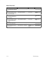
Fault Messages . . . . . . . . . . . . . . . . . . . . . . . . . . . . . . . . . . . . . . . . . . . . . . . . 4–3
48 Volt Failed * . . . . . . . . . . . . . . . . . . . . . . . . . . . . . . . . . . . . . . . . . . . . 4–3
Dynamic RAM Fault . . . . . . . . . . . . . . . . . . . . . . . . . . . . . . . . . . . . . . . . 4–5
Ham. Bank Hot * . . . . . . . . . . . . . . . . . . . . . . . . . . . . . . . . . . . . . . . . . . . 4–6
Ham. Coil Open * . . . . . . . . . . . . . . . . . . . . . . . . . . . . . . . . . . . . . . . . . . 4–7
Ham. Coil Short * . . . . . . . . . . . . . . . . . . . . . . . . . . . . . . . . . . . . . . . . . . 4–8
Ham. Drv. Short * . . . . . . . . . . . . . . . . . . . . . . . . . . . . . . . . . . . . . . . . . . 4–9
Mech Driver Hot * . . . . . . . . . . . . . . . . . . . . . . . . . . . . . . . . . . . . . . . . . . 4–10
Mech Driver Link * . . . . . . . . . . . . . . . . . . . . . . . . . . . . . . . . . . . . . . . . . 4–11
Paper Jam . . . . . . . . . . . . . . . . . . . . . . . . . . . . . . . . . . . . . . . . . . . . . . . . . 4–12
Paper Out . . . . . . . . . . . . . . . . . . . . . . . . . . . . . . . . . . . . . . . . . . . . . . . . . 4–13
Platen Open . . . . . . . . . . . . . . . . . . . . . . . . . . . . . . . . . . . . . . . . . . . . . . . 4–14
Ribbon Stall . . . . . . . . . . . . . . . . . . . . . . . . . . . . . . . . . . . . . . . . . . . . . . . 4–15
Shuttle Fan * . . . . . . . . . . . . . . . . . . . . . . . . . . . . . . . . . . . . . . . . . . . . . . 4–16
Shuttle Jam . . . . . . . . . . . . . . . . . . . . . . . . . . . . . . . . . . . . . . . . . . . . . . . . 4–17
Software Error * . . . . . . . . . . . . . . . . . . . . . . . . . . . . . . . . . . . . . . . . . . . . 4–18
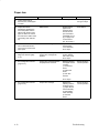
Troubleshooting Symptoms Not Indicated by Fault Messages . . . . . . . . . . . 4–19
Troubleshooting Aids . . . . . . . . . . . . . . . . . . . . . . . . . . . . . . . . . . . . . . . . . . . 4–19
Printer Confidence Check . . . . . . . . . . . . . . . . . . . . . . . . . . . . . . . . . . . . . . . . 4–20
CCB Diagnostic Checks . . . . . . . . . . . . . . . . . . . . . . . . . . . . . . . . . . . . . . . . . 4–21
Diagnostic Self–Tests . . . . . . . . . . . . . . . . . . . . . . . . . . . . . . . . . . . . . . . . . . . 4–27
Running the Diagnostic Self–Tests . . . . . . . . . . . . . . . . . . . . . . . . . . . . . . . . . 4–29
Hex Code Printout . . . . . . . . . . . . . . . . . . . . . . . . . . . . . . . . . . . . . . . . . . . . . 4–30
Clearing Nonvolatile Memory (NVRAM) . . . . . . . . . . . . . . . . . . . . . . . . . . . 4–32
ii
Table of Contents
5
Adjustments
Hammer Bank Service Position . . . . . . . . . . . . . . . . . . . . . . . . . . . . . . . . . . . 5–2
Hammer Spring Retensioning . . . . . . . . . . . . . . . . . . . . . . . . . . . . . . . . . . . . . 5–8
Hammer Tip Alignment . . . . . . . . . . . . . . . . . . . . . . . . . . . . . . . . . . . . . . . . . 5–10
Magnetic Pickup Gap Adjustment . . . . . . . . . . . . . . . . . . . . . . . . . . . . . . . . . 5–12
Magnetic Pickup Phasing . . . . . . . . . . . . . . . . . . . . . . . . . . . . . . . . . . . . . . . . 5–14
Paper Feed Belt Tension . . . . . . . . . . . . . . . . . . . . . . . . . . . . . . . . . . . . . . . . . 5–16
Paper Out Switch Adjustment . . . . . . . . . . . . . . . . . . . . . . . . . . . . . . . . . . . . 5–18
Platen Gap Adjustment . . . . . . . . . . . . . . . . . . . . . . . . . . . . . . . . . . . . . . . . . . 5–22
Platen Open Belt Adjustment . . . . . . . . . . . . . . . . . . . . . . . . . . . . . . . . . . . . . 5–24
Ribbon Tracking Check and Adjustment . . . . . . . . . . . . . . . . . . . . . . . . . . . . 5–26
Shuttle and Counterweight Preload . . . . . . . . . . . . . . . . . . . . . . . . . . . . . . . . 5–28
Shuttle and Counterweight Spring Adjustment . . . . . . . . . . . . . . . . . . . . . . . 5–32
Shuttle Belt Tension Adjustment . . . . . . . . . . . . . . . . . . . . . . . . . . . . . . . . . . 5–36
6
Replacement Procedures and Parts
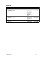
Replacement Procedures
Blower Assembly . . . . . . . . . . . . . . . . . . . . . . . . . . . . . . . . . . . . . . . . . . . . . . 6–4
Cabinet Cooling Fan . . . . . . . . . . . . . . . . . . . . . . . . . . . . . . . . . . . . . . . . . . . . 6–5
Card Cage Fan . . . . . . . . . . . . . . . . . . . . . . . . . . . . . . . . . . . . . . . . . . . . . . . . 6–6
Control Panel . . . . . . . . . . . . . . . . . . . . . . . . . . . . . . . . . . . . . . . . . . . . . . . . . 6–7
Counterweight Assembly . . . . . . . . . . . . . . . . . . . . . . . . . . . . . . . . . . . . . . . . 6–8
(Shuttle) Cam and Flywheel . . . . . . . . . . . . . . . . . . . . . . . . . . . . . . . . . . . . . . 6–9
Gas Shock . . . . . . . . . . . . . . . . . . . . . . . . . . . . . . . . . . . . . . . . . . . . . . . . . . . . 6–11
Hammer Bank . . . . . . . . . . . . . . . . . . . . . . . . . . . . . . . . . . . . . . . . . . . . . . . . . 6–12
Hammer Cover Assembly . . . . . . . . . . . . . . . . . . . . . . . . . . . . . . . . . . . . . . . . 6–23
Hammer Spring and Hammer Coil . . . . . . . . . . . . . . . . . . . . . . . . . . . . . . . . . 6–24
I/O Panel and Cable Assembly . . . . . . . . . . . . . . . . . . . . . . . . . . . . . . . . . . . . 6–25
Magnetic Pickup Assembly (MPU) . . . . . . . . . . . . . . . . . . . . . . . . . . . . . . . . 6–26
Oil Wick . . . . . . . . . . . . . . . . . . . . . . . . . . . . . . . . . . . . . . . . . . . . . . . . . . . . . 6–26
Paper Feed Motor and Belt . . . . . . . . . . . . . . . . . . . . . . . . . . . . . . . . . . . . . . . 6–27
Table of Contents
iii
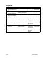
Paper Motion/Out Detector . . . . . . . . . . . . . . . . . . . . . . . . . . . . . . . . . . . . . . . 6–28
Platen Open Motor and Belt . . . . . . . . . . . . . . . . . . . . . . . . . . . . . . . . . . . . . . 6–29
Platen Open Switch . . . . . . . . . . . . . . . . . . . . . . . . . . . . . . . . . . . . . . . . . . . . . 6–30
Printed Circuit Board Assemblies (PCBAs) . . . . . . . . . . . . . . . . . . . . . . . . . . 6–32
Power Supply . . . . . . . . . . . . . . . . . . . . . . . . . . . . . . . . . . . . . . . . . . . . . . . . . 6–31
Ribbon Hub . . . . . . . . . . . . . . . . . . . . . . . . . . . . . . . . . . . . . . . . . . . . . . . . . . . 6–33
Ribbon Motor . . . . . . . . . . . . . . . . . . . . . . . . . . . . . . . . . . . . . . . . . . . . . . . . . 6–34
Shuttle Motor . . . . . . . . . . . . . . . . . . . . . . . . . . . . . . . . . . . . . . . . . . . . . . . . . 6–35
Shuttle Motor Belt . . . . . . . . . . . . . . . . . . . . . . . . . . . . . . . . . . . . . . . . . . . . . 6–36
Tractor Assemblies . . . . . . . . . . . . . . . . . . . . . . . . . . . . . . . . . . . . . . . . . . . . . 6–37
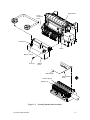
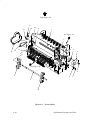
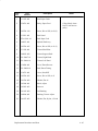
Illustrated Parts Lists
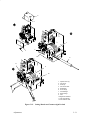
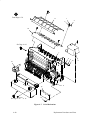
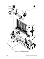
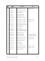
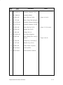
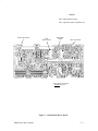
Printer Assembly . . . . . . . . . . . . . . . . . . . . . . . . . . . . . . . . . . . . . . . . . . . . . . 6–38
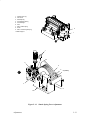
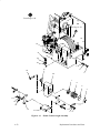
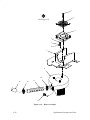
Print Mechanism . . . . . . . . . . . . . . . . . . . . . . . . . . . . . . . . . . . . . . . . . . . . . . . 6–40
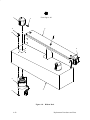
Ribbon Deck . . . . . . . . . . . . . . . . . . . . . . . . . . . . . . . . . . . . . . . . . . . . . . . . . . 6–42
Tractor Shafts . . . . . . . . . . . . . . . . . . . . . . . . . . . . . . . . . . . . . . . . . . . . . . . . . 6–44
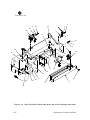
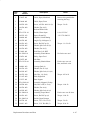
Paper Feed and Platen Open Motors,
Paper Out and Platen Open Switches . . . . . . . . . . . . . . . . . . . . . . . . . . . . . . . 6–46
Hammer Bank Assembly . . . . . . . . . . . . . . . . . . . . . . . . . . . . . . . . . . . . . . . . 6–48
Hammer Springs and Coils . . . . . . . . . . . . . . . . . . . . . . . . . . . . . . . . . . . . . . . 6–50
Shuttle Counterweight Assembly . . . . . . . . . . . . . . . . . . . . . . . . . . . . . . . . . . 6–52
Shuttle Cam and Flywheel . . . . . . . . . . . . . . . . . . . . . . . . . . . . . . . . . . . . . . . 6–54
Card Cage and Control Panel (CCB) . . . . . . . . . . . . . . . . . . . . . . . . . . . . . . . 6–56
Blower Assembly . . . . . . . . . . . . . . . . . . . . . . . . . . . . . . . . . . . . . . . . . . . . . . 6–58
Power Supply and I/O Assembly . . . . . . . . . . . . . . . . . . . . . . . . . . . . . . . . . . 6–60
iv
Table of Contents
7
Appendices
A
Wire Data
B
Abbreviations, Acronyms, and Signal Mnemonics
C
PROM and Chip Locations
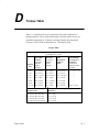
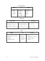
D
Torque Table
E
Metric Conversion Tables
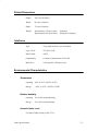
F
Printer Specifications
Table of Contents
v
vi
Table of Contents
1
Overview
Chapter Contents
About This Manual . . . . . . . . . . . . . . . . . . . . . . . . . . . . . . . . . . . . . . 1–2
How to Use This Manual . . . . . . . . . . . . . . . . . . . . . . . . . . . . . . 1–2
Warnings and Special Information . . . . . . . . . . . . . . . . . . . . . . . 1–2
Printing Conventions in this Manual . . . . . . . . . . . . . . . . . . . . . 1–3
Controls and Indicators . . . . . . . . . . . . . . . . . . . . . . . . . . . . . . . . . . . 1–4
Electrical Controls and Indicators . . . . . . . . . . . . . . . . . . . . . . . . 1–4
Mechanical Controls . . . . . . . . . . . . . . . . . . . . . . . . . . . . . . . . . . 1–6
Tools, Test Equipment, and Supplies . . . . . . . . . . . . . . . . . . . . . . . . . 1–8
Overview
1–1
About This Manual
This is a field service maintenance manual for the LG12 Text and Graphics
printer.
This manual does not explain how to operate or configure the printer. For
that information, refer to the User’s Manual.
How to Use This Manual
This manual is designed so that you can quickly find the information you
need to service the printer. You can locate maintenance information three
ways:
♦
Use the Table of Contents at the front of the manual.
♦
Use the Chapter Contents listed at the front each chapter.
♦
Use the Index at the back of the manual.
Read the entire procedure before beginning any maintenance task.
Gather all required tools and make sure you understand all warnings,
cautions, and notes before you begin working on the printer.
Warnings and Special Information
Always comply with information printed under the following headings:
WARNING
Conditions that can harm you and damage the printer.
CAUTION
Conditions that can damage the printer.
IMPORTANT
Information vital to proper operation of the printer.
NOTE: Information important enough to emphasize.
1–2
Overview
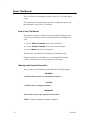
Printing Conventions in This Manual
Switches, indicators, and switch positions that are labeled on the printer are
printed in uppercase letters.
Example: Press the CLEAR switch.
Messages that appear on the liquid crystal display of the control panel are
printed in quotation marks.
Example: Press the CLEAR switch. “Off–Line Emulation” appears on the
LCD.
Overview
1–3
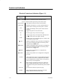
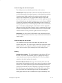
Controls and Indicators
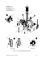
Electrical Controls and Indicators (Figure 1–1)
Switch or
Indicator
NOTE:
ON LINE is the only switch that operates when the printer is
on–line. All other switches operate only in the off–line state.
Power Switch
Turns printer on and off. Is also a circuit breaker.
Status lamps
Illuminate when printer is on–line. Flash alternately to
indicate fault or warning. Off when printer is off–line.
LCD
Liquid Crystal Display. Shows printer status and error
messages.
Toggles the printer on–line and off–line.
ON LINE
FF
Advances paper to top of form on next page.
LF
Advances paper to top of next print line. When pressed
with switch, micro–steps paper vertically.
VIEW
Advances paper for viewing through cover window, then
returns paper to print position.
(UP)
Displays configuration menus, submenus, and diagnostic
tests. Locks and unlocks ENTER switch when pressed
simultaneously with switch.
(DOWN)
Displays configuration menus, submenus, and diagnostic
tests. Locks and unlocks ENTER switch when pressed
simultaneously with switch.
(PREV)
Displays previous parameter in a configuration or
diagnostic test menu.
(NEXT)
Displays next parameter in a configuration or diagnostic
test menu.
CLEAR
Clears printer after a fault is corrected. Returns printer to
off–line state from within a configuration menu. When
pressed simultaneously with R/S switch, resets printer to
most recently saved configuration.
R/S
Runs and stops configuration and self tests. Runs and
stops hex dump. Resets printer to most recently saved
configuration when pressed simultaneously with CLEAR
switch.
SET TOF
ENTER
1–4
Function
Sets location of first line of print on a page.
Enters displayed parameter into printer nonvolatile
memory. Must be unlocked before using.
Overview
Printer Cover
On
Power Switch
Off
Status Lamps
Liquid Crystal Display (LCD)
CLEAR
UP
R/S
PREV
NEXT
SET TOF
ON LINE
FF
LF
VIEW
ENTER
DOWN
RAISE PRINTER
COVER TO ACCESS
THESE SWITCHES
Figure 1–1. Electrical Controls and Indicators
Overview
1–5
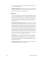
Mechanical Controls
(Figure 1–2)
Control or
Indicator
1–6
Function
Forms thickness
lever
Sets platen for paper and forms of different thicknesses.
Must be raised to load paper.
Forms thickness
pointer and scale
Indicates relative thickness of paper. Set the forms
thickness lever at A for thin (single–part) forms, B for
thicker forms, and so on.
Tractors (2)
Hold and feed paper. Also used to set left side margin.
Tractor locks (2)
Lock tractors in position.
Horizontal
adjustment knob
Allows fine positioning of left print margin. Moves
paper left or right.
Vertical
adjustment knob
Used to set top of form or first line to be printed. Rotate
to move paper vertically.
Overview
Tractor Lock
Tractor Lock
Horizontal
Adjustment
Knob
Vertical
Adjustment
Knob
Forms
Thickness
Pointer and Scale
Forms
Thickness
Lever
Tractor
Figure 1–2. Mechanical Controls
Overview
1–7
Tools, Test Equipment, and Supplies
The tools, test equipment, and supplies required for field level maintenance
of LG12 printers are listed below.
Item
Part Number
Recommended Item
Adjustable Wrench
—
Utica 91–4C
Alcohol, Anhydrous
—
—
29–26246–01
—
Diagonal Cutters
—
Erem 91EH
Digital Voltmeter
—
—
Extension, 3 in., 3/8 Drive
—
—
Feeler Gauge Set
—
Proto 000AA
Force Gauge
29–24411–00
—
IC Insertion/Extraction Tool
29–24015–00
—
—
—
29–30945–01
—
Nut Driver Set
—
Xcelite P2120
Oscilloscope and Probes (≥ 35 MHz)
—
—
134742–001
—
Pliers, Grip Ring
—
Truarc 1120
Pliers, Chain Nose
—
Erem 11DH
Ratchet, 3/8 in. Drive
—
—
Rule, Steel, 6 in.
—
General 616
Scale, Spring, 0 to 40 lbs.
—
—
Driver, Torque Screwdriver
29–17381–00
Utica TS35
Adapter, Torque Screwdriver
29–24723–00
Utica HW–18
Extension, 6 in., Torque Screwdriver
—
—
Hex Bit, 3/16 in., Torque Screwdriver
29–20995–00
Utica W–8
Hex Bit, 3/32 in., Torque Screwdriver
29–18505–00
Utica HW–4
Hex Bit, 5/32 in., Torque Screwdriver
24–18504–00
Utica HW–6
Hex Bit, 5/64 in., Torque Screwdriver
—
—
Hex Key Set, 15 PC
—
McMaster–Carr Supply,
Cat. No. 7125A11
Screwdriver, Allen Hex
—
Xcelite 99PS40
Screwdriver, Phillips
—
Xcelite X100
Screwdriver, Phillips
—
Xcelite X102
Anti–Static Workstation, Pocket
Kimwipes
Lubricant, Bearing
Packaging Kit
1–8
Overview
Item
Part Number
Recommended Item
Screwdriver, Slot
—
Xcelite A184
Screwdriver, Slot
—
Xcelite R3164
Screwdriver, Stubby, 1.5 in shank, 0.25 in
tip–width
—
—
Shim, Antirotation (0.010 in.)
29–30943–01
—
Shim, Antirotation (0.005 in.)
29–30944–01
—
Shims, Counterweight
29–24417–00
—
Shims, Shuttle Spring
29–24420–00
—
Socket, 7/16 in., 3/8 in. Drive
—
—
Soldering Iron and Tips
—
—
Tool, Antirotation
29–30905–01
—
Tool, Hammer Alignment
FD–28262–01
—
—
—
X–acto Knife and Blades
Overview
1–9
1–10
Overview
2
Principles of Operation
Chapter Contents
Line Matrix Printing . . . . . . . . . . . . . . . . . . . . . . . . . . . . . . . . . . . . . 2–2
Functional Elements of the Printer . . . . . . . . . . . . . . . . . . . . . . . . . . 2–9
Control Panel . . . . . . . . . . . . . . . . . . . . . . . . . . . . . . . . . . . . . . . . . . . 2–11
Common Controller Board (CCB) . . . . . . . . . . . . . . . . . . . . . . . . . . 2–12
CCB Hardware Summary . . . . . . . . . . . . . . . . . . . . . . . . . . . . . . 2–17
Mechanism Driver Board . . . . . . . . . . . . . . . . . . . . . . . . . . . . . . . . . 2–21
Hammer Driver Board . . . . . . . . . . . . . . . . . . . . . . . . . . . . . . . . . . . . 2–25
Auto–Ranging Power Supply . . . . . . . . . . . . . . . . . . . . . . . . . . . . . . 2–28
Print Mechanisms . . . . . . . . . . . . . . . . . . . . . . . . . . . . . . . . . . . . . . . 2–29
Hammer Bank, Shuttle, and MPU . . . . . . . . . . . . . . . . . . . . . . . 2–29
Ribbon Deck . . . . . . . . . . . . . . . . . . . . . . . . . . . . . . . . . . . . . . . . 2–31
Paper Feed Control . . . . . . . . . . . . . . . . . . . . . . . . . . . . . . . . . . . 2–32
Principles of Operation
2–1
Line Matrix Printing
The LG12 creates characters and graphics by a printing technique called line
matrix printing. Line matrix printing consists of printing patterns of ink dots
on paper, an entire line at a time.
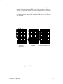
Each text character is stored in memory as a pattern of dots on a logical grid
called the dot matrix. (See Figure 2–1.) The actual ink dots are made by a
row of hammer springs mounted on a shuttle that sweeps rapidly back and
forth. Printer logic divides every printable line into horizontal dot rows. The
hammer springs put dots at the required positions for the entire line by
striking a moving ink ribbon and the paper.
1
Column No.
0.10 ”
12
0.00835 ”
First row and column
of next character.
0.01389 ”
Lowest descender
dot line.
First row and column of
next character line (at 6
LPI).
0.02 ”
Figure 2–1. A Dot Matrix
When the shuttle reaches the end of a sweep, it reverses direction, the paper
is advanced one dot row, and the hammer springs print the next row of dots
as the shuttle sweeps in the opposite direction. After a line of characters is
printed, hammer action stops and the paper advances to the first dot row of
the next print line. The number of dot rows allowed for line separation
depends on the vertical line spacing the user selects.
2–2
Principles of Operation
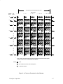
The dot patterns of characters vary according to the font selected. For
example, in the data processing (DP) font at a line spacing of six lines per
inch (lpi), the dot matrix contains 12 dot rows from the top of one character
line to the top of the next. (See Figure 2–1 and Figure 2–2.) At eight lpi there
are nine dot rows per character line, at nine lpi eight dot rows per character
line, and so on.
Uppercase
(Reference)
Underline
Lowercase with Descender
Figure 2–2. Typical Characters
Principles of Operation
2–3
The Hammer Bank
The LG12 uses a hammer bank to print dots. The hammer bank consists of
88 hammer springs mounted on a shuttle that moves horizontally back and
forth. The hammer bank prints one horizontal line of dots during each
horizontal sweep of the shuttle.
A hammer spring is a stiff leaf spring with a hardened steel tip at the upper
end, and is attached to the hammer bank at the lower end. (See Figure 2–3.)
A permanent magnet keeps the hammer springs retracted and under tension.
Behind every hammer is a pair of magnetic coils which, when energized,
neutralize the field of the permanent magnet. This releases the hammer,
which springs forward and strikes the ribbon and paper, leaving a dot. The
hammer is recaptured by the permanent magnet as it rebounds. (See
Figure 2–4.)
2–4
Principles of Operation
Ribbon
Ribbon Mask
Hammer Bank Cover
Paper
Hammer Tip
Magnet
Coil
Coil
Platen
Shuttle Shaft
Hammer Spring
Hammer Spring Mounting Screw
Paper Ironer
Figure 2–3. Hammer Spring and Shuttle Arrangement
Normal (retracted) State
Coils de–energized
Activated (released) State
Coils energized
Permanent Magnet
Coil
Coil
Coil
Hammer
Tip
Coil
Hammer
Spring
Figure 2–4. Hammer Spring Action
Principles of Operation
2–5
Character Generation
Paper advances one dot row after each horizontal sweep of the shuttle. (See
Figure 2–5 and Figure 2–6.)
Direction of Shuttle Movement
Dot
Row
Character
Row
1
2
3
4
5
6
7
8*
9**
10
11
12
1
2
Paper
Advances
Start
Paper
Feed
Paper
Advances
Space
1 Hammer
Print Span
The LG12 shuttle sweeps
through 1.5 character positions
at 10 cpi.
1 Hammer
Print Span
*
Used for lowercase descender only.
**
Used for underline and lowercase
descender.
Figure 2–5. Standard Character Formation
2–6
Principles of Operation
Successive Hammer Strokes Per Scan
Dot Column
Shuttle
Scan
Dot
Row
1
1
2
1
2
3
1
2
3
4
1
2
3
4
5
1
2
3
4
5
6
1
2
3
4
5
6
7
1
2
3
4
5
6
7
* 1
*
NOTE:
* 1 3
* 1 3 5
* 1 3 5 7
*
1 3 5 7 9
*
Even column dot centers within the printed character area and character space
hammer positions are not illustrated in this diagram.
= Dot
=No dot where hammer has already been
= Hammer Position
Figure 2–6. Character Formation by One Hammer
Principles of Operation
2–7
Normal Operation
In normal operation, the user presses a switch on the control panel to put the
printer on–line. Host computer data are then read into the input buffer as
ASCII data. The data in the input buffer are compared to tables stored in
memory to determine the matrix and location of each character The
characters are then built in the dot image buffer.
Information from the dot image buffer is synchronized with printer
requirements using the magnetic pickup signal, then shifted to the hammer
drivers. The selected hammers are fired.
When all dots in a row are printed, the paper advances one dot row and the
next dot row of data from the dot image buffer are synchronized then shifted
to the hammer drivers. Vertical paper movement is delayed to allow double
printing if adjacent dot printing is required. (See Figure 2–7.)
During self–tests, data stored in ROM are used to build the dot image buffer.
Operation then proceeds as in normal printing.
Input Data Buffer
(Dynamic RAM)
ASCII data (DPU)
**
Control Panel
Printer Setup
Printer Enable
Build dot image from
lookup tables. Put into
Dynamic RAM (DPU).
Synchronize timing to
codewheel (MPU)
software.
Printer Interface:
Host Input Data
Demand hammer load
data be shifted to
hammer driver. **
Fire hammers on next
MPU. (Software timers.)
No
** Controlled by
software, executed
by hardware.
Software
decision
All dots in
row
printed?
Yes
Move paper.
(Mech. Driver)
Figure 2–7. The Print Cycle
2–8
Principles of Operation
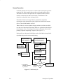
Functional Elements of the Printer
The printer consists of six functional elements:
♦
Control panel
♦
Common controller board (CCB)
♦
Mechanism driver board
♦
Hammer driver board
♦
Auto–ranging power supply
♦
Print mechanism
Figure 2–8 is a block diagram of these elements.
The rest of this chapter discusses these systems in more detail.
Principles of Operation
2–9
+12.5Vdc
ON / OFF
Switch
AUTO–RANGING
POWER SUPPLY
EMI
FILTER
Circuit Brkr
AC
POWER
HAMMER
DRIVER
BOARD
POWER
SUPPLY
FAN
HOST
COMPUTER
Data
PRINT
MECHANISMS
+48 Vdc
HMR DRV 1–40
+12.5Vdc
12V / 48V FILTER
BLR DRIVE
+48 Vdc
Crowbar
Data
+5 Vdc
Status
COMMON
CONTROLLER
BOARD
Fault
DPU
Paper
Control
+5 Vdc
Keyboard
Shuttle
Timing
SHARED
MEMORY
Hmrs
41–88
MECHANISM
DRIVER
BOARD
Shuttle Drive
FAULT CIRCUITS
PAPER TRANSPORT
DRIVE
SHUTTLE DRIVE
MPU
RIBBON DRIVE
P/S CIRCUITS
Message
Indicator
HAMMER
BANK
SHUTTLE
ASSEMBLY
Control
Fault Hmrs
1–40
+48 Vdc
Status
Hmrs
1–88
+5 Vdc
CARD CAGE
FAN
PRINTER
INTERFACE
BLOWER
ASSEMBLY
BLR
Control
HMR DRV 41–88
Paper Feed
Motor Control
PAPER
TRANSPORT
Platen Open
Motor Control
Hammer
Driver Data
Hammer
Timing Data
RTPU
Shuttle & Ribbon
Control
CONTROL PANEL
Ribbon Status
RIBBON
TRANSPORT
Ribbon Control
PAPER
OUT
PLATEN
OPEN
PAPER
MOTION
Sensors
Figure 2–8. Functional Elements of the LG12 Printer
2–10
Principles of Operation
Control Panel
The control panel consists of indicator lamps, LEDs, contact switches, and a
liquid crystal display (LCD).
The control panel processes and sends switch closure information to the
controller board and receives status information.
Control Panel Assembly
Switch
Closures
Status
Control Panel
Circuit Board Assembly
Control
Data
Switch
Closures
Common Controller Board (CCB)
Figure 2–9. Control Panel Block Diagram
Principles of Operation
2–11
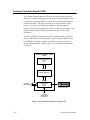
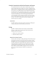
Common Controller Board (CCB)
The Common Controller Board (CCB) oversees and coordinates all printer
functions. It is functionally two units: the data processing unit (DPU) and the
real–time processing unit (RTPU). The DPU converts all character data into
printable dot images. The DPU is the high–level logical controller of the
printer; it is not involved in real–time or hardware–dependent printer
operation. The RTPU operates the host interfaces, operator control panel, and
the print mechanism. The RTPU also monitors the fault circuitry in the
mechanism.
The DPU and RTPU communicate by means of shared memory. The DPU
gets host and operator input from buffers in shared memory which are filled
by the RTPU, and returns dot images and operator messages to buffers in
memory which the RTPU empties. Figure 2–10 summarizes the architecture
of the CCB.
Common Controller Board
(CCB)
DATA PROCESSING
UNIT
(DPU)
SHARED MEMORY
PRINTER
INTERFACE
REAL–TIME
PROCESSING
UNIT
(RTPU)
CONTROL PANEL
PRINTING
MECHANISM
INTERFACE
Figure 2–10. Architectural Overview of the CCB
2–12
Principles of Operation
Controller Communication with the Host Computer and Operator
The controller board processes three kinds of computer input: Centronics
parallel, DataProducts parallel, and RS–232 serial data. The RTPU operates
all three interfaces. The parallel interfaces are similar, and the RTPU contains
direct–memory–access (DMA) hardware which loads parallel data directly
into shared memory. The serial interface requires byte–by–byte intervention
by the processor, since ACK/NACK and XON/XOFF protocols require that
every byte be examined as it is received. The universal asynchronous
receiver/transmitter (UART) is internal to the RTPU, which processes any
protocol requirements then puts the data in shared memory, where the DPU
can read it. To the DPU, all input data look the same, regardless of the
interface used to receive the data.
Control Panel
The RTPU handles the control panel interface requirements of shifting and
clocking control panel data, but the DPU processes the data.
Printing
The RTPU coordinates printing of the dot images sent from the DPU.
Printing is a complex process requiring many control functions, but is
logically divided into two groups:
•
Hammer driver interface functions
•
Mechanical interface functions
Hammer Driver Interface Functions
In order to print a dot image, two things must happen. First, the dots must get
to the hammers one dot row at a time and in the correct sequence. Second,
the hammers must be fired at the appropriate time in the stroke of the shuttle.
The RTPU microprocessor controls both of these functions, but each is
actually performed by an application–specific integrated circuit (ASIC)
containing hardware dedicated to the function. These ASICs are the Dot
Plucker Memory Controller (DPMC) and the Fire Timer IC (FTIC). The
hammer driver interface functions of the RTPU are summarized in
Figure 2–11.
Principles of Operation
2–13
DATA PROCESSING
UNIT
(DPU)
SHARED MEMORY
DOT PLUCKER
ASIC
Hammer
Driver
Data
RTPU
PROCESSOR
EPROM
DMA CONTROLLER
FIRE TIMER
ASIC
Hammer
Timing
Data
REAL–TIME PROCESSING UNIT
Figure 2–11. Hammer Driver Interface Functions of the RTPU
Getting Dots to the Hammers Getting dots to the hammers consists of
going into the shared memory and pulling bits out in a given order and
shifting them to the hammer driver at the correct time. This process is called
“dot plucking.” The order in which dots are plucked from memory depends
on the dot density, the number of dots per hammer, the number of hammers
on the hammer bank, the number of phases, and other factors. These factors
are all considered by the RTPU processor as it programs the dot plucker and
the FTIC for each dot row.
Synchronizing Dot Plucking and Hammer Firing Transfer of dots to the
hammer driver must be synchronized with hammer firing. Dots are
transferred to the hammer driver in bursts, serial streams of dots that tell
which hammers will print when their phase is next fired. The bursts are timed
precisely; they must occur neither too early nor too late. Synchronization is
performed by having the FTIC request bursts from the dot plucker. The FTIC
reads the magnetic pick–up unit (MPU) to determine when to request a burst.
The time at which the burst request is made is contained in the fire timing
tables.
2–14
Principles of Operation
Mechanical Interface Functions
Three mechanical operations are coordinated in printing: paper motion,
ribbon motion, and shuttle motion. Virtually all digital handling of paper
motion is contained in the RTPU. The ribbon and shuttle are controlled by
logic on the mechanism driver board, under the direction of the RTPU.
Figure 2–12 shows the mechanical interface section of the RTPU.
DATA PROCESSING
UNIT
SHARED MEMORY
DOT PLUCKER
REAL–TIME PROCESSING UNIT
RTPU
PROCESSOR
EPROM
UART
PAPER FEED
CONTROLLER
Shuttle
and
Ribbon
Control
Paper
Control
Figure 2–12. Mechanical Interface Functions of the RTPU
Paper Motion The DPU determines when paper must be moved and how far
to move it. It communicates this to the RTPU through the shared memory.
The RTPU processor performs some paper handling operations (such as
holdback on slews), but most RTPU paper handling is done by a dedicated
microcontroller called the paper feed controller (PFC).
The PFC moves paper by looking up motion profiles and driving a sequence
of motor positions to the mechanism driver board. If the motion is a dot row
or interline advance, it is synchronized to hammer firing by a signal from the
FTIC that tell the PFC when to move.
Ribbon and Shuttle Motion The ribbon and shuttle motors are controlled
by a microcontroller on the mechanism driver board. The RTPU interface to
Principles of Operation
2–15
the ribbon/shuttle processor (RSP) is a 2400 baud asynchronous serial line. A
message protocol is used to communicate ribbon and shuttle information.
Fault Monitoring
The RTPU also monitors the hammer driver, mechanism driver, and the
electro–mechanical sensors for fault conditions. Fault conditions are reported
to the DPU.
Hammer Bank and Hammer Driver Faults
The FTIC works with the hammer driver ASIC to monitor coil shorts, opens,
average upper driven phase current, and temperature conditions. The RTPU
reads the FTIC registers to determine out–of–range conditions, and these are
passed on to the DPU.
Paper Faults
Two kinds of paper faults can occur: paper out and paper jammed. Both of
these conditions are monitored through optical sensors. The paper feed
controller watches the paper out and paper motion sensors and reports errors
to the RTPU. The RTPU passes this information on to the DPU.
Ribbon and Shuttle Faults
The mechanism driver ribbon and shuttle controller monitors fault conditions
in the drive circuits and notifies the RTPU if it finds errors. The RTPU can
also use the FTIC to measure time between magnetic pick–up (MPU) pulses,
enabling it to monitor shuttle speed and thus detect some shuttle faults.
2–16
Principles of Operation
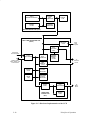
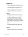
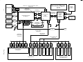
CCB Hardware Summary
A Motorola 68010 microprocessor performs the DPU functions, a 64180
microprocessor handles the RTPU functions, and an 8032 microcontroller
serves as the paper feed controller (PFC), which is part of the RTPU. Actual
implementation of this hardware blurs the distinctions between the DPU and
RTPU, since the 68010 has access to the parallel port and the real–time
functions of the dot plucker, which are RTPU resources, while the 64180 has
access to the nonvolatile memory (NVRAM), which is a resource of the
DPU. These possibilities exist because of efficiencies in the hardware design;
software maintains the functional differences between the DPU and RTPU.
The CCB has four data buses:
♦
The 68010 has a local sixteen bit bus.
♦
The 64180 uses a local bus eight bits wide.
♦
The DPU and RTPU share a sixteen bit bus arbitrated on a
cycle–by–cycle basis.
♦
The 8032 chip has its own eight bit local bus.
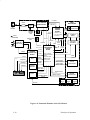
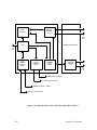
The manner in which the CCB implements this hardware is depicted in
Figure 2–13.
The 64180 IC that oversees the RTPU processor contains a Z80
microprocessor with extended memory management, two DMA controllers,
two asynchronous and one synchronous serial port, two counter timers, and
an interrupt controller.
Principles of Operation
2–17
68010
MICROPROCESSOR
SHARED
BUS
INTERFACE
EPROM
512 KB
CONTROL
REGISTER
NVRAM
2 KB
DATA PROCESSING UNIT (DPU)
REAL–TIME PROCESSING UNIT
(RTPU)
PARALLEL
PORT
From
Host
Computer
DOT
PLUCKER
ASIC
Serial from
Host Computer
64180
PROCESSOR
Serial to Host,
Mech. Driver, and
Control Panel
SHARED
BUS
INTERFACE
SHARED
MEMORY
DRAM
512 KB
To
Hammer
Driver
FIRE
TIMER IC
(FTIC)
EPROM
64 KB
HARDWARE
CONTROL
REGISTER
SRAM
2 KB
HARDWARE
STATUS
REGISTER
COMM.
PORT
8032
PROCESSOR
PAPER FEED
CONTROLLER
(PFC)
EPROM
16 KB
To
Mech.
Driver
Figure 2–13. Hardware Implementation of the CCB
2–18
Principles of Operation
Communicating with the Host Computer
The 64180 processor runs both the parallel and serial interfaces.
Parallel Input Parallel input data is nine bits wide, and is transferred in one
cycle from the parallel port to shared memory over the shared sixteen bit bus.
Using the internal DMA controller of the 64180 to transfer parallel data
requires some manipulation. The eight bit DMA controller in the 64180
performs either eight or sixteen bit DMA cycles, while the eight bit processor
in the 64180 performs only eight bit memory access cycles. Sixteen bit DMA
is achieved by hardware shifting of the DMA addresses one bit (effectively
multiplying the address by two and changing the DMA auto–increment from
byte to word) and by manipulating the control strobe. Software adjusts the
addresses provided to the DMA controller when it is programmed for sixteen
bit DMA. This manipulation saves both the added cost of a sixteen bit DMA
controller and the second cycle that an eight bit transfer would require.
Serial Input One of the 64180 UARTs handles serial communication with
the host. Additional modem control lines are provided in the 64180 hardware
control register.
Communicating with the Operator
The synchronous serial port in the 64180 shifts data in and out of the
operator control panel. The control register in the RTPU contains three other
control panel bits: one samples the switches, one strobes the liquid–crystal
display, and one strobes a light–emitting diode (LED) holding register.
Printing
Hammer Driver Interface The 64180 programs the dot plucker ASIC and
the FTIC every stroke, after which the FTIC uses a DMA request line to
control the movement of tables from EPROM to FTIC. The second DMA
controller in the 64180 performs this transfer.
Mechanism Driver Interface The paper feed controller (PFC) directs all
paper motion. During printing, it usually moves paper in response to a trigger
from the FTIC, which synchronizes paper motion with shuttle motion. The
64180 programs the PFC 8032 at the beginning of each dot row, telling the
PFC how far to move when the trigger is received. The PFC sets up for the
move, waits, then moves when the trigger occurs. The other method of
starting paper motion is with a command to move paper immediately. This
Principles of Operation
2–19
results in immediate movement. Other paper commands and status signals
are also passed through this port.
Ribbon and Shuttle Motion The 64180 interfaces through its second UART
to the ribbon / shuttle processor (RSP) on the mechanism driver board. The
64180 begins all transactions on the serial interface.
Fault Monitoring
The RTPU 64180, the PFC 8032, and the RSP monitor different functions for
faults. The 64180 looks for hammer driver faults, shuttle stalls, and an open
platen. The PFC 8032 monitors paper out and the paper motion detector. The
RSP watches for faults in the motor drive circuits. The PFC and RSP report
errors to the 64180, which collates fault status and passes it on to the DPU
68010 processor.
Hammer Bank and Hammer Driver Faults The 64180 and FTIC check the
hammer driver and hammer bank for faults on every shuttle stroke. Faults are
detected by circuits on the mechanism driver and hammer driver boards and
relayed to the CCB. Fault circuitry can detect rising temperatures in the coils.
One coil is checked on every shuttle stroke; therefore, 88 shuttle strokes are
required to check all coils. When the RTPU is notified of a fault, it sends a
message to the 68010. The hammer driver and mechanism driver boards also
continuously monitor for shorts in hammer driver circuits and cables. If they
detect currents that can harm the hammer bank, the +48 volt power supply is
shut down by “crowbar” circuitry within 70 milliseconds.
Paper Faults The PFC 8032 monitors paper faults and reports them to the
64180 through the eight bit parallel port they share. The PFC works with a
friction wheel paper motion detector and a reflective (optical) paper out
sensor. The sensors interface directly to the CCB; analog circuits on the CCB
condition the sensor inputs.
Ribbon and Shuttle Faults The RSP monitors ribbon and shuttle faults and
reports them to the 64180 over the serial interface.
2–20
Principles of Operation
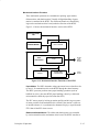
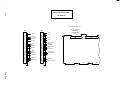
Mechanism Driver Board
The mechanism driver board, acting on timing and control signals from the
CCB, controls real–time operation of the electromechanical printer systems.
Functionally, the board consists of the following subsystems:
•
An 8032 microcontroller controls ribbon, shuttle, and platen drives,
and communication with the controller board. This 8032 is called
the RSP (Ribbon/Shuttle/Platen) controller.
•
The interface to the power supply.
•
Pulse–width modulator (PWM) current mode / voltage mode
full–bridge power amplifiers connected directly to the shuttle,
ribbon, paper feed, and platen open motors. Current mode is used
for the paper feed motor, voltage mode is used for the ribbon and
shuttle motors.
•
The paper feed controller (PFC) accepts control codes from the
controller board for each motor phase to vector–control the paper
feed motor.
•
The shuttle drive controller receives speed commands from the
controller board through the 8032 microcontroller and commands
the speed of the three–phase brushless DC shuttle motor.
•
The ribbon drive controller, based around the 8032 microcontroller,
receives commands from the controller board and drives two DC
stepper motors, regulating the speed and tension of the ribbon and
monitoring the end of ribbon sensors.
•
The platen drive controller for reverse paper feed receives
commands from the 8032 microcontroller (RSP).
•
Fault detection circuitry samples and senses heat sink temperature,
ribbon speed, shuttle speed, hammer driver circuitry, hammer bank
coil temperatures, power supply voltages, and fault communication
with the controller board.
•
Circuitry that registers magnetic pick–up unit (MPU) output,
processes it for the logic interface, and sends it to the controller
board for timing hammer fire.
Figure 2–14 summarizes mechanism driver board operation in block diagram
form.
Principles of Operation
2–21
MECHANISM DRIVER BOARD
HAMMER
DRIVERS
41–88
FAULT
CIRCUITS
To
Coils
41–88
HAMMER DRIVE BOARD
LOGIC
To
CCB
8032
RIBBON
&
SHUTTLE
DRIVE
PAPER
TRANSPORT
DRIVE
HAMMER
DRIVER
LOGIC
HAMMER
DRIVERS
1–40
To
Coils
1–40
PAPER FEED CONTROL
PLATEN OPEN CONTROL
RIBBON CONTROL & STATUS
SHUTTLE DRIVE & MPU
Figure 2–14. Operational Overview of the Mechanism Driver Board
2–22
Principles of Operation
The Ribbon Drive System
The ribbon drive system is controlled by the 8032 microcontroller. The
controller board sends commands to the 8032 to start and stop the ribbon, set
the ribbon speed, and apply slack or tension to the ribbon. The real–time
control functions are done by the 8032, acting in accordance with firmware
control algorithms and look–up tables. The 8032 communicates with an
ASIC to provide direct digital PWM drive signals for the ribbon motor PWM
amplifier. The 8032 drives the ribbon motors through PWM generators in the
mechanism driver integrated circuit (MDIC). Nearly all mechanical control
functions are carried out through the MDIC ASIC. Digital I/O is done
through latches connected to the 8032 I/O ports and MDIC. Ribbon faults are
passed to the controller board.
Ribbon Velocity
Ribbon velocity is controlled by means of a closed–loop system that first
measures the speed of the two ribbon drive motors. One motor is driven; the
other motor is not driven and applies tension to the ribbon through its drag
circuitry. The velocity of the driven motor is known, while the velocity of the
tensioning motor is measured by converting the zero crossing of the
back–EMF signal to a digital pulse signal. This signal is processed by the
8032 to determine the radius of the ribbon on the take–up reel. The processor
monitors this information and adjusts the velocity of the driven motor to
maintain constant linear speed. The roles of the two motors reverse at the end
of ribbon travel, when a metallic strip crosses the ribbon guide of the
emptying reel and closes a circuit that causes the RSP to reverse motor
functions.
The four PWM amplifiers in the ribbon drive system are voltage mode to aid
in system damping (as opposed to current mode). The 8032 input to the
PWM amplifiers maintains a constant voltage/frequency ratio at the motor.
The ribbon drive is protected from over current.
Ribbon Tension
The 8032 processor regulates tension in three discrete steps by using
information gathered by the zero–crossing circuitry and ribbon information.
Tension is adjusted by controlling the load on the drag motor back emf. This
load generates drag torque on the ribbon hub that maintains tension.
Principles of Operation
2–23
Start / Stop Ribbon
The ribbon motors are started and stopped by a digital signal from the
controller board. After a stop signal is received, the ribbon is locked to
maintain tension. If the controller board sends a slack signal, the PWM
amplifiers are tri–stated.
The Shuttle Drive System
The shuttle drive system is an analog closed–loop speed controller that
accepts commands from the controller board through the 8032
microcontroller and MDIC ASIC. The controller board writes a word
containing start, stop, and speed data to the 8032, which in turn writes a word
to the MDIC. The MDIC generates a clock signal based on this word.
The shuttle is protected from overspeed and over current.
The Paper Feed System
Dot row advance and slew tables are stored in the controller board The paper
feed drive circuit takes commands directly from the controller board to
control the two–phase DC paper feed stepper motor. A controller board paper
feed command is a digital word containing a value proportional to the desired
current level in the paper feed motor, enabling the motor to be
quarter–stepped. Two PWM current mode amplifiers, protected against
overloads and short circuits, drive the paper feed motor. The paper feed
motor is usually energized whenever printer power is on in order to maintain
tension and position of the paper. The paper feed motor is disabled in a
platen open, paper jam, or paper out fault condition.
The Reverse Paper Feed System
To reverse paper motion, the printer must open the platen, move the paper
backwards vertically, close the platen, and remove the slack in the paper. A
platen open or close command is generated on the controller board and
communicated to the RSP 8032 processor. The RSP generates control and
step clock signals for the platen driver circuitry. The platen driver circuitry is
connected to a stepper motor that drives the platen through a toothed belt.
The platen motor is only energized during the open and close cycles. The
platen driver is protected from over current.
2–24
Principles of Operation
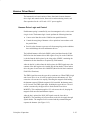
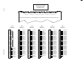
Hammer Driver Board
The hammer driver board consists of three functional elements: hammer
driver logic and control circuits, blower drive and monitoring circuits, and
filter capacitors for the +48 V and +12.5 V power supplies.
Hammer Driver Logic and Control
Each hammer spring is controlled by two electromagnetic coils, a driver, and
a logic circuit. The hammer logic circuits perform the following functions:
♦
Convert serial data bits on the COM line into parallel data bits.
♦
Control the energizing of hammer coils to print dots in accordance with
the parallel data.
♦
Provide safety features to prevent coils from energizing under conditions
that could damage the coils and hammer drivers.
The buffered hammer shift clock (BHSC) pulses load data from the COM
DATA line into the hammer driver shift register. Every bit on the COM line
is clocked into the shift register by the rising edge of BHSC, containing dot
information for the characters to be printed by each hammer.
After the last bit is clocked into the shift register, the FIRE signal causes the
contents of the shift register to be loaded into the data latches. These latches
drive the gates of each lower drive MOSFET (Metal Oxide Semi–conductor
Field Effect Transistor).
The FIRE signal also turns the upper drive transistors on. When FIRE is high
and a lower driver is on, 48 volts are applied across the hammer coil. This
causes the coil current to rise rapidly, cancelling the magnetic field holding
the hammer retracted. With the magnetic field cancelled, the hammer starts
to fly forward. The FIRE signal drops, disabling the upper drivers. The coil
current is sustained by the upper driver diodes and the lower driver
MOSFETs. This combination applies 12.5 volts across the coil, keeping the
magnetic field cancelled until hammer impact.
After the dot is printed, the NLD_RST signal resets the lower driver
MOSFETs. The remaining coil current returns to the 48 volt supply through
flyback diodes. The magnetic field is restored and the permanent magnet
captures the hammer. (See Figure 2–15.)
Principles of Operation
2–25
Test Mode
12.5 V
V
ramp
+48 V
Coil Temp.
&
Open Detect
+24
V
bootstrap
Level
Shift
12.5
VSUS
HD Coil Temp.
Flyback
Diodes
12.5 1%
Boot
Strap
Window Compare
&
Fault Detect
HD Short
Hammer
Coil
LD
FET
COM
CLK
FIRE
Shift
Register
Latch
NLD_RST
Figure 2–15. Hammer Driver Logic
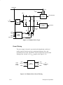
Power Filtering
The power supply is housed in a protected and independently cooled steel
module separate from the card cage containing the hammer driver and
mechanism driver boards. The hammer driver board therefore provides bulk
filtering of the +48 and +12.5 (VSUS) supplies. (See Figure 2–16.)
+48V
From
Power
Supply
+12.5V
GND
+48V
Filter
Capacitors
+12.5V
GND
To
Mechanism
Driver
Figure 2–16. Hammer Driver Power Filtering
2–26
Principles of Operation
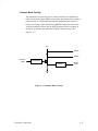
Hammer Bank Cooling
The hammer driver board also powers a blower fan that cools the hammer
bank. A fixed 60/40 signal (PWM) is provided to the hammer driver board to
run the blower fan. The hammer driver board demodulates this signal to a
binary (on/off) logic signal, then drives a MOSFET that powers the blower.
A current monitoring circuit tells the RTPU when the blower is running. If
the blower is stalled or not connected, the RTPU declares a fault. (See
Figure 2–17.)
48 V
Blower +
Blower –
Bank Fan
PWM
Demodulator
Blower
Running
Blower
Fault
Figure 2–17. Hammer Bank Cooling
Principles of Operation
2–27
Auto–Ranging Power Supply
The power supply board, AC input connector, power switch/circuit breaker,
and a cooling fan are contained in a removable steel module at the rear of the
printer. The power supply senses and adjusts to any commercial electrical
system that provides AC mains potential in 50 or 60 Hertz systems. AC input
power is converted to +48 volt and +12.5 volt DC power and sent to the
hammer driver board for bulk filtering. The hammer driver board then passes
the filtered +48 and +12.5 Vdc to the mechanism driver board for
distribution to logic and electromechanical circuits.
AC Power
The power supply operates on AC voltages ranging from 88 to 135 or
176 to 270 volts. It can tolerate variations in frequency of 47 to 63 Hz. The
power supply is designed to withstand an AC input overvoltage of 125% of
nominal for one second with no degradation of DC output voltage or damage
to printer circuits.
DC Power
The power supply board contains two DC power supply systems for the
printer. The first is a + 5 volt bus for logic circuits. The second consists of
+ 48 volt and + 12.5 volt buses for the electromechanical sections of the
printer (all drive motors and the hammer bank).
The + 5 volt and + 48/12.5 volt supplies have separate return lines. Both
returns are tied together in a single–point ground at the mechanism driver
board.
There is an opto–isolated logic level input from the printer that can shut
down and latch off the + 48 volt and + 12.5 volt supplies while maintaining
the + 5 volt output. The return for this signal is the + 5 volt return. In
addition, this shutdown circuit discharges and latches the + 48 volt down to
a level lower than 15 volts in less than 300 milliseconds and requires
recycling of the power switch/circuit breaker to reset the latch.
The + 5 volt power supply has its own inverter, separate from the + 48 volt
and + 12.5 volt outputs to provide logic power if the +48/12.5 volt supply is
shut down.
2–28
Principles of Operation
Print Mechanisms
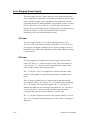
Hammer Bank, Shuttle, and MPU
Printing is synchronized with shuttle movement by signals from the magnetic
pickup unit (MPU). The MPU, located next to the flywheel timing disk, is so
oriented that timing signals relate precisely to the shuttle position. (See
Figure 2–18.) Variations in magnetic reluctance are sensed by the MPU from
apertures on the timing disk as it rotates, generating SYNC pulses. Two
aperture locations at opposite ends of the disk are of double width (material
between two adjacent apertures is removed). These double width apertures
separate the 284 single width apertures into two groups and generate a
RESYNC signal coincident with the shuttle starting to move from left to
right.
One rotation of the disk provides four back–and–forth shuttle cycles, which
equals eight printing periods. Each printing period is followed by a
turnaround period when the shuttle movement is reversed, paper is advanced
a distance determined by the vertical dot density, and no printing occurs.
Typical signal levels received from the magnetic pickup are:
SYNC: 2.5 to 5.5 Vpp
RESYNC: 4 Vpp minimum
Operation of the hammer bank and shuttle is also described on page 2–4.
Principles of Operation
2–29
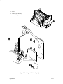
Hammer Bank and Shuttle Assembly
Shuttle Motor
(Shuttle Mechanics)
MPU
Figure 2–18. Hammer Bank and Shuttle Mechanical Elements
2–30
Principles of Operation
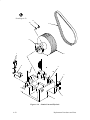
Ribbon Deck
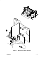
The printer ribbon winds and unwinds continuously on a pair of spools
latched to hubs driven by the ribbon motors. The ribbon motors operate only
while the hammer bank assembly is running. Ribbon motion reverses when
the metal strip at either end of the ribbon crosses the left or right ribbon
guide, completing a circuit that causes both motors to reverse direction.
Constant ribbon tension is maintained by controlling each motor with a drive
or drag circuit. While the hammer bank assembly is in motion, one motor
acts as a driving motor, drawing the ribbon against the resistance exerted by
the other motor—the drag motor. This system maintains a constant motor
speed and constant ribbon tension.
Figure 2–19. Ribbon Deck
Principles of Operation
2–31
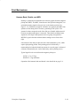
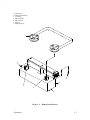
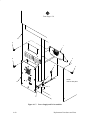
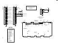
Paper Feed Control
The paper transport system accepts continuous, fan–folded, edge–perforated
paper from three to 16 inches wide and from one to six sheets thick. (See
Appendix F for precise paper specifications.) Horizontal positioning is
provided by the horizontal adjustment knob and two tractors. The tractors are
laterally adjustable along the splined and support shafts. Each tractor engages
paper perforations with eight pins and locks in place with a friction lock.
During printing, the paper feed motor drives the splined shaft with a toothed
belt. The splined shaft drives the tractors. The paper feed drive motor is a
two–phase step motor controlled by the paper feed sections of the
mechanism driver board and the paper feed controller on the CCB.
Paper is manually advanced with the vertical adjustment knob.
Tractors
Horizontal
Adjustment
Knob
Paper Feed Motor
Vertical
Adjustment
Knob
Support
Shaft
Splined
Shaft
Friction
Lock
Figure 2–20. Paper Feed Components
2–32
Principles of Operation
3
Preventive Maintenance
Chapter Contents
Preventive Maintenance . . . . . . . . . . . . . . . . . . . . . . . . . . . . . . . . . . . 3–2
Cleaning the Printer . . . . . . . . . . . . . . . . . . . . . . . . . . . . . . . . . . . . . . 3–2
Preventive Maintenance
3–1
Preventive Maintenance
The LG12 printer requires no preventive maintenance beyond normal
replenishment of paper and ribbons and periodic cleaning. Since operating
conditions vary widely, the user must determine how often to clean the
printer.
Cleaning the Printer
CAUTION
Do not use abrasive cleaners, particularly on the window. Do not drip
water into the printer; damage to equipment will result. When using
spray solutions, do not spray directly onto the printer; spray the cloth.
1. Turn the printer off.
2. Disconnect the printer power cord.
3. Open the printer cover.
4. Remove paper from the printer.
5. Wipe the cabinet exterior with a clean, lint–free cloth dampened (not
wet) with water and mild detergent or window cleaning solution.
6. Dry the cabinet with a clean, lint–free cloth.
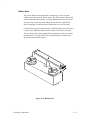
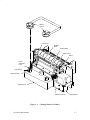
7. Open the forms thickness lever all the way. (See Figure 3–1.)
8. Squeeze the lock tabs on the ribbon hubs and remove the ribbon spools.
9. Using a soft–bristled brush, remove paper dust and ribbon lint from the
tractors, ribbon deck, ribbon path, and base casting. Vacuum up the
residue.
10. Wipe the splined shaft and support shaft with a soft cloth.
CAUTION
To avoid corrosion damage, use only anhydrous alcohol to clean the
print mechanism.
11. Using a cloth dampened with anhydrous alcohol, clean the ribbon guides.
3–2
Preventive Maintenance
Ribbon
Spools
Left Tractor
Splined
Shaft
Support Shaft
Right Tractor
Platen
Forms
Thickness
Lever
Lock Tab (2)
Ribbon Hub (2)
Ribbon Deck
Ribbon Guide (2)
Figure 3–1.
Preventive Maintenance
Base Support
Cleaning Interior of Cabinet
3–3
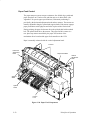
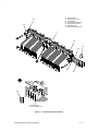
12. Wipe the platen with a cloth dampened with anhydrous alcohol.
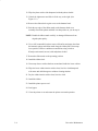
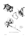
13. Unlock the right tractor and slide it all the way to the right. (See
Figure 3–2.)
14. Remove the ribbon deck to gain access to the hammer bank.
15. Push the top edge of the ribbon mask on the hammer bank cover
assembly toward the platen and hold it in that position as you do step16.
NOTE: Handle the ribbon mask carefully. A damaged ribbon mask can
degrade print quality.
16. Use a stiff, nonmetallic brush to remove ribbon lint and paper dust from
the hammer springs and ribbon mask along the ribbon path. Vacuum up
loose particles. Remove stubborn accumulations using a cloth or
Kimwipe moistened (not wet) with anhydrous alcohol.
17. Return the ribbon mask to the operating position.
18. Install the ribbon deck.
19. Vacuum up dust or residue that has accumulated inside the lower cabinet.
20. Wipe the lower cabinet interior with a clean, lint–free cloth dampened
with water and mild detergent or window cleaning solution.
21. Dry the cabinet interior with a clean, lint–free cloth.
22. Install the ribbon.
23. Install the printer power cord.
24. Load paper.
25. Close the printer cover and return the printer to normal operation.
3–4
Preventive Maintenance
Right Tractor
Forms
Thickness
Lever
Lock Tab (2)
Platen
Ribbon Hub (2)
Screw (3)
Ribbon
Deck
Ribbon Mask
Hammer Spring
Hammer Bank
Cover
Hammer TIp
Figure 3–2.
Preventive Maintenance
Cleaning Hammer Bank Assembly
3–5
3–6
Preventive Maintenance
4
Troubleshooting
Chapter Contents
Introduction . . . . . . . . . . . . . . . . . . . . . . . . . . . . . . . . . . . . . . . . . . . . 4–3
Fault Messages . . . . . . . . . . . . . . . . . . . . . . . . . . . . . . . . . . . . . . . . . . 4–3
48 Volt Failed * . . . . . . . . . . . . . . . . . . . . . . . . . . . . . . . . . . . . . . 4–3
Dynamic RAM Fault . . . . . . . . . . . . . . . . . . . . . . . . . . . . . . . . . . 4–5
Ham. Bank Hot . . . . . . . . . . . . . . . . . . . . . . . . . . . . . . . . . . . . . . 4–6
Ham. Coil Open * . . . . . . . . . . . . . . . . . . . . . . . . . . . . . . . . . . . . 4–7
Ham. Coil Short * . . . . . . . . . . . . . . . . . . . . . . . . . . . . . . . . . . . . 4–8
Ham. Drv. Short * . . . . . . . . . . . . . . . . . . . . . . . . . . . . . . . . . . . . 4–9
Mech Driver Hot * . . . . . . . . . . . . . . . . . . . . . . . . . . . . . . . . . . . 4–10
Mech Driver Link * . . . . . . . . . . . . . . . . . . . . . . . . . . . . . . . . . . . 4–11
Paper Jam . . . . . . . . . . . . . . . . . . . . . . . . . . . . . . . . . . . . . . . . . . 4–12
Paper Out . . . . . . . . . . . . . . . . . . . . . . . . . . . . . . . . . . . . . . . . . . . 4–13
Platen Open . . . . . . . . . . . . . . . . . . . . . . . . . . . . . . . . . . . . . . . . . 4–14
Ribbon Stall . . . . . . . . . . . . . . . . . . . . . . . . . . . . . . . . . . . . . . . . . 4–15
Shuttle Fan * . . . . . . . . . . . . . . . . . . . . . . . . . . . . . . . . . . . . . . . . 4–16
Shuttle Jam . . . . . . . . . . . . . . . . . . . . . . . . . . . . . . . . . . . . . . . . . 4–17
Software Error * . . . . . . . . . . . . . . . . . . . . . . . . . . . . . . . . . . . . . 4–18
Troubleshooting Symptoms Not Indicated by Fault Messages . . . . . 4–19
Troubleshooting Aids . . . . . . . . . . . . . . . . . . . . . . . . . . . . . . . . . . . . 4–19
Printer Confidence Check . . . . . . . . . . . . . . . . . . . . . . . . . . . . . . . . . 4–20
CCB Diagnostic Checks . . . . . . . . . . . . . . . . . . . . . . . . . . . . . . . . . . 4–21
Troubleshooting
4–1
Diagnostic Self–Tests . . . . . . . . . . . . . . . . . . . . . . . . . . . . . . . . . . . . 4–27
Running the Diagnostic Self–Tests . . . . . . . . . . . . . . . . . . . . . . . . . . 4–29
Hex Code Printout . . . . . . . . . . . . . . . . . . . . . . . . . . . . . . . . . . . . . . . 4–30
Clearing Nonvolatile Memory (NVRAM) . . . . . . . . . . . . . . . . . . . . 4–32
4–2
Troubleshooting
Introduction
This chapter contains procedures for troubleshooting printer malfunctions.
Diagnostic test procedures are covered in this chapter, but basic printer
operation is not. Since you must operate the printer to check its performance,
have the Operator‘s Guide or User‘s Manual at the printer site.
Fault Messages
This section contains troubleshooting tables for fault messages that can
appear on the Liquid Crystal Display (LCD).
Two kinds of faults can appear on the LCD:
♦
Operator correctable faults
♦
Faults requiring the attention of a field service technician—indicated
with an asterisk (*) after the fault message
IMPORTANT
Test printer operation after every corrective action, and stop
troubleshooting when the symptom disappears. Always press the
CLEAR switch after correcting a fault indicated by a fault message.
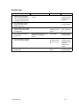
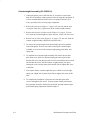
48 Volt Failed *
Instruction
1. Cycle power: Turn printer off.
Indication
Yes
“48 Volt Failed * ” message.
Go to step 2.
Return printer to
normal operation.
“48 Volt Failed * ” message.
Go to step 3.
Return printer to
normal operation.
Wait 15 seconds. Turn printer
on.
2. Press the CLEAR switch.
No
3. Turn printer off.
—
Go to step 4.
4. Disconnect CCB/Mech
—
Go to step 5.
—
Driver cable from connector
J2 on the controller board
and connector J6 on the
mech driver board.
Troubleshooting
4–3
Instruction
5. Turn printer on and observe
Indication
power supply fan.
7. Cycle power and observe the
power supply fan.
8. Cycle power and observe the
power supply fan above the
on/off switch.
9. Cycle power and check for
Replace the
controller board.
Reattach
CCB/Mech Driver
cable to connector
J2 on the
controller and
connector J6 on
the mech driver
board, and go to
step 6.
Power supply fan runs, then
stops.
Replace the
mech. driver
board.
Go to step 7.
Power supply fan runs, then
stops, with new mech. driver
board installed.
Replace the
hammer driver
board.
Go to step 8.
Power supply fan does not run
at all.
Replace the
power supply.
Return printer to
normal operation.
“48 Volt Failed * ” message.
Replace +5V
cable assembly.
(See Appendix A.)
Go to step 10.
Return printer to
normal operation.
“48 Volt Failed * ” message.
Replace Hi
voltage cable
assembly. (See
Appendix A.) Go
to step 11.
Return printer to
normal operation.
“48 Volt Failed * ” message.
Replace Main
Wire Harness.
(See Appendix A.)
Go to step 12.
Return printer to
normal operation.
“48 Volt Failed * ” message.
Replace hammer
bank cables. (See
Appendix A.)
Return printer to
normal operation.
the fault message.
10. Cycle power and check for
the fault message.
11. Cycle power and check for
the fault message.
12. Cycle power and check for
the fault message.
4–4
No
Card cage fan comes on.
card cage fan: feel for air flow
beneath the card cage.
6. Cycle power and observe the
Yes
Troubleshooting
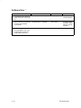
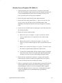
Dynamic RAM Fault *
Instruction
1. Cycle power: Turn printer off.
Wait 15 seconds. Turn printer
on.
2. Disconnect the input data line
from the host computer. Set
power switch to off. Wait 15
seconds. Set power switch to
on.
3. Make a Diagnostic Check of
Indication
Yes
No
“Dynamic RAM Fault * ”
message.
Go to step 2.
Return printer to
normal operation.
“Dynamic RAM Fault * ”
message.
Go to step 3.
Return printer to
normal operation.
—
—
—
the CCB (page 4–21). If any
problems are found on the
CCB, replace the board.
Troubleshooting
4–5
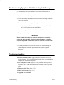
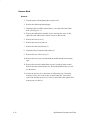
Ham. Bank Hot
NOTE: The printer has protective circuits that sense conditions which can
lead to overheating. When such conditions are sensed, print speed
is reduced 50%. If the printer consistently prints at half speed, it
may be printing long jobs of very dense graphics or operating in a
severe environment. A severe environment is consistently above 90°
Fahrenheit (32° Celsius) or is dirty enough to create blockage of the
blower ducts. If the printer is located in such an environment,
consider relocating it to a cooler, cleaner area or reducing the size
and duration of the print jobs.
Instruction
Indication
Yes
No
1. Press the CLEAR switch.
The printer continues the print
job.
No further
attention required.
The printer
continues original
print job then fault
message
reappears.
2. Check ambient temperature
Printer area at or above 100° F
(37° C).
Allow hammer
bank to cool for 10
minutes. Cool
printer area or
reduce size and
duration of print
jobs.
Go to step 3.
Unobstructed air flow through
blower duct.
Go to step 4.
Remove
obstructions from
blower
assemblies.
“Ham. Bank Hot” message.
Replace the
hammer bank.
Run the hammer
bank diagnostics
program to
calibrate the coils
(page NO TAG).
Return the printer
to normal
operation.
where printer is operated.
3. Run a diagnostic self–test
(page 4–27).
4. Cool the hammer bank for 2
hours. (It must be at room
temperature.) Run the
hammer bank diagnostics
program to calibrate the coils
(page NO TAG). Run a
diagnostic self–test (page
4–27).
4–6
Troubleshooting
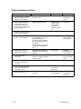
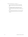
Ham. Coil Open *
Instruction
Indication
Yes
No
“Ham. Coil Open * ” message.
Go to step 2.
Return printer to
normal operation.
2. Press the CLEAR switch.
“Ham. Coil Open * ” message.
Go to step 3.
Return printer to
normal operation.
3. Run a diagnostic self–test
“Ham. Coil Open * ” message.
Go to step 4.
Return printer to
normal operation.
Observe where the non–printing
hammer is located.
Go to step 5.
—
Go to step 6.
—
1. Cycle power: Turn printer off.
Wait 15 seconds. Turn printer
on.
(page 4–27).
4. Run a diagnostic self–test
(page 4–27).
5. Switch hammer bank cable
—
connectors at the hammer
driver board. (Top connectors
are for the left side of the
hammer bank.)
6. Run a diagnostic self–test
(page 4–27). Observe where
the non–printing hammer is
located.
7. Return the hammer bank
cables to their correct
connectors on the hammer
driver board. Run a
diagnostic self–test (page
4–27).
Troubleshooting
Position of the non–printing
hammer remains the same.
Replace the
offending coil then
go to step 7.
If the non–printing
hammer is 1–40,
replace the
hammer driver
board. If the
non–printing
hammer is 41–88,
replace the
mechanism driver
board. Go to step
7.
“Ham. Coil Open * ” message.
Replace the
hammer bank
cables.
Return printer to
normal operation.
4–7
Ham. Coil Short *
Instruction
1. Cycle power: Turn the printer
Indication
Yes
No
“Ham. Coil Short * ” message.
Go to step 2.
Return the printer
to normal
operation.
Resistance is 4–8 Ohms for all
coils.
Go to step 4.
For coils less than
4 Ohms, go to
step 3.
Coil resistance still less than 4
Ohms.
Replace the coil.
Go to step 4.
Cable resistance is more than
1K Ohm.
For hammers 1 –
40, replace the
hammer driver
board. For
hammers 41 – 88,
replace the
mechanism driver
board.
Replace the
hammer driver
cable.
off. Wait 15 seconds. Turn
the printer on.
2. Turn the printer off. Remove
the ribbon deck. Measure the
coil resistance at hammer
bank connectors J1 – J6:
each coil has a red and a
white wire; put probes where
wire enters the top of the
connector.
3. If a coil is less than 4 Ohms,
disconnect its hammer bank
connector and measure the
coil resistance again, as in
step 2.
4. Disconnect the hammer bank
cable connectors J1 – J6.
Measure resistance of the
coil leads of the hammer
driver cable. (You are
checking resistance through
both the hammer driver cable
and the hammer driver board.
Do not disconnect the
hammer driver cable at the
hammer driver board. See
Appendix A for pin
assignments.)
4–8
Troubleshooting
Ham. Drv. Short *
Instruction
Indication
Yes
No
“Ham. Drv. Short * ” message.
Go to step 2.
Return printer to
normal operation.
2. Press the CLEAR switch.
“Ham. Drv. Short * ” message.
Go to step 3.
Return printer to
normal operation.
3. Disconnect connectors J4,
“Ham. Drv. Short * ” message.
Replace the
mechanism driver
board.
Go to step 4.
“Ham. Drv. Short * ” message.
Replace the
hammer driver
board.
Return printer to
normal operation.
“Ham. Drv. Short * ” message.
Disconnect
hammer driver
cables one by one
until offending
cable is isolated.
Go to step 6.
Return printer to
normal operation.
1. Cycle power: Turn printer off.
Wait 15 seconds. Turn printer
on.
J5, and J6 from hammer
driver board. Cycle power.
4. Disconnect connectors J1,
J2, J3, and J4 from the
hammer driver board.
Connect J5 and J6. Cycle
power.
5. Connect all cables. Cycle
power.
6. Check resistance to ground
of all contacts in the bad
cable.
Troubleshooting
If any measure 100 KΩ to
ground, replace the cable and
the coil.
Return printer to
normal operation.
4–9
Mech Driver Hot *
Instruction
Indication
Yes
No
“Mech Driver Hot * ” message.
Go to step 2.
Return printer to
normal operation.
Card cage fan operates.
Go to step 3.
Replace the card
cage fan.
Cabinet exhaust fan operates.
Go to step 4.
Replace the
cabinet exhaust
fan.
Power supply fan operates.
Go to step 5.
Replace power
supply.
5. Press the CLEAR switch.
“Mech Driver Hot * ” message.
Go to step 6.
Return printer to
normal operation.
6. Run a diagnostic self–test
“Mech Driver Hot * ” message.
Replace
mechanism driver
board.
Return printer to
normal operation.
1. Cycle power: Turn printer off.
Wait 15 seconds. Turn printer
on.
2. Observe operation of card
fan: check for air flow at the
bottom of card cage.
3. Observe operation of cabinet
exhaust fan: check for air
flow out of the grid at the rear
of the printer.
4. Observe operation of power
supply fan above the on/off
switch at the rear of the
printer.
(page 4–27).
4–10
Troubleshooting
Mech Driver Link *
Instruction
Indication
Yes
No
“Mech Driver Link * ” message.
Go to step 2.
Return printer to
normal operation.
2. Press the CLEAR switch.
“Mech Driver Link * ” message.
Go to step 3.
Return printer to
normal operation.
3. Run a diagnostic self–test
“Mech Driver Link * ” message.
Go to step 4.
Return printer to
normal operation.
—
Go to step 5.
—
1. Cycle power: Turn printer off.
Wait 15 seconds. Turn printer
on.
(page 4–27).
4. Remove the card cage cover.
5. Check ribbon cable
connectors between
controller board and
mechanism driver board.
6. Check installation of
Connectors are attached
properly.
Go to step 6.
Connect and latch
ribbon connectors.
Go to step 6.
Boards are installed correctly.
Go to step 7.
Reseat controller
and mechanism
driver boards in
their edge
connectors at
back of card cage.
Go to step 8.
RTPU and RSP EPROMs and
microprocessors are correct
versions and installed correctly.
Go to step 8.
Install correct
RTPU and RSP
EPROMs and
microprocessors.
controller board and
mechanism driver board.
7. Check for correct installation
and revision levels of
EPROMs and
microprocessors for the
RTPU on the controller board
and RSP on the mechanism
driver board. (Appendix E.)
8. Power up printer and check
Go to step 8.
“Mech Driver Link * ” message.
Replace the
controller board,
then go to step 9.
Return printer to
normal operation.
“Mech Driver Link * ” message.
Replace the
mechanism driver
board, then go to
step 10.
Return printer to
normal operation.
“Mech Driver Link * ” message.
Replace
CCB/Mech. Dr.
cable. (See
Appendix A.)
Return printer to
normal operation.
for fault message.
9. Power up printer and check
for fault message.
10. Power up printer and check
for fault message.
Troubleshooting
4–11
Paper Jam
Instruction
1. Inspect paper path for
Indication
Yes
No
Paper path is clear.
Go to step 2.
Remove paper
and go to step 2.
Debris found.
Gently remove
paper or lint
particles with a
wooden stick or
pair of tweezers.
CAUTION: Do not
pry or apply force
to the hammer
tips. Go to step 3.
Go to step 3.
Ribbon mask damaged or bent.
Replace the
hammer bank
cover assembly.
Go to step 4.
Go to step 4.
Paper moves correctly but
“Paper Jam” message still
appears.
Clean the paper
motion detector
with cotton swab.
Go to step 5.
Go to step 5.
“Paper Jam” message appears
and paper does not move.
Replace following
until paper moves
correctly:
1) mech driver
board
2) paper feed
motor
3) main wire
harness
Return printer to
normal operation.
bunched, torn, folded paper
or labels.
2. Inspect the narrow
passageway between the
face of the platen and the
ribbon mask for bits of torn
paper or ribbon lint. Check
the holes in the ribbon mask
surrounding each hammer
tip.
3. Check that the ribbon mask
has not been deformed in
such a way as to block the
paper path.
4. Load paper and run a
diagnostic self–test (page
4–27).
5. Run a diagnostic self–test
(page 4–27).
Go to step 6.
6. Run a diagnostic self–test
(page 4–27).
4–12
“Paper Jam” message.
Replace the
following until the
message clears:
1) paper detector
switch assembly.
2) intermediate
cable assembly.
3) controller
board.
Return printer to
normal operation.
Troubleshooting
Paper Out
Instruction
1. Load paper.
2. Run a diagnostic self–test
Indication
—
(page 4–27).
Troubleshooting
—
Replace paper
detector switch
assembly. Adjust
the new paper
motion switch
assembly
(Chapter 4). Go to
step 3.
Return printer to
normal operation.
“Paper Out” message.
Replace the
sensor harness
assembly. Go to
step 4.
Return printer to
normal operation.
“Paper Out” message.
Replace the
controller board.
Return printer to
normal operation.
(page 4–27).
4. Run a diagnostic self–test
Go to step 2.
No
“Paper Out” message.
(page 4–27).
3. Run a diagnostic self–test
Yes
4–13
Platen Open
Instruction
1. Load paper and close the
Indication
—
Yes
No
Go to step 2.
—
forms thickness lever.
2. Run a diagnostic self–test
“Platen Open” message.
Replace platen
interlock switch
assembly. Go to
step 3.
Return printer to
normal operation.
“Platen Open” message.
Replace sensor
harness assembly.
Go to step 4.
Return printer to
normal operation.
“Platen Open” message.
Replace the
controller board.
Return printer to
normal operation.
(page 4–27).
3. Run a diagnostic self–test
(page 4–27).
4. Run a diagnostic self–test
(page 4–27).
4–14
Troubleshooting
Ribbon Stall
Instruction
1. Check that forms thickness
lever is not closed too tightly;
this can jam the ribbon and
shuttle.
2. Run a diagnostic self–test
Indication
Yes
Forms thickness lever is set
correctly.
Go to step 2.
Readjust the
setting of the
forms thickness
lever.
Go to step 2.
“Ribbon Stall” message.
Go to step 3.
Return printer to
normal operation.
Ribbon path is clear.
Go to step 4.
Remove
obstructions from
ribbon path and
go to step 4.
Ribbon is OK. (Folds are
permitted, if the ribbon is
otherwise undamaged.)
Rewind and
reinstall ribbon.
Go to step 5.
Replace ribbon, if
damaged. Unfold
and rewind ribbon
if it was folded.
Go to step 5.
Ribbon tracks OK.
Go to step 6.
Align ribbon
guides.
Go to step 6.
Only one motor winds the
ribbon.
Replace the
following until
symptom clears:
1) mechanism
driver board.
2) defective ribbon
drive motor.
Return printer to
normal operation.
(page 4–27) and check for
shuttle obstruction.
3. Check ribbon path for
blockage or obstruction.
4. Wind ribbon by hand and
inspect for folds, tears, holes,
fraying.
5. Do a fast shuttle self–test
(page 4–27) and check the
alignment of the ribbon
guides and hubs if the ribbon
was folded.
6. Using a screwdriver, short
across the ribbon guide
screws to reverse ribbon hub
motion. Check for a ribbon
drive motor that will not wind
ribbon.
Troubleshooting
No
4–15
Shuttle Fan *
Instruction
1. Cycle power: Turn printer off.
Indication
Yes
No
“Shuttle Fan” message.
Go to step 2.
Return printer to
normal operation.
Blower starts and runs, but
“Shuttle Fan” message displays.
Go to step 3.
Go to step 4.
Cables are connected and
undamaged.
Replace the
controller and
hammer driver
boards.
Replace the
defective cable
assembly.
“Shuttle Fan” message displays
and blower does not run.
Replace the
blower. Go to step
5.
Return printer to
normal operation.
“Shuttle Fan” message displays
and blower does not run.
Replace the
hammer driver
board. Go to step
6.
Return printer to
normal operation.
“Shuttle Fan” message displays
and blower does not run.
Replace the
mechanism driver
board. Go to step
7.
Return printer to
normal operation.
“Shuttle Fan” message displays
and blower does not run.
Replace the
power supply high
voltage cable
assembly.
Return printer to
normal operation.
Wait 15 seconds. Turn printer
on.
2. Run a shuttle/ribbon
diagnostic test (page 4–27)
and observe the blower fan.
3. Turn off the printer. Check all
cable connections between
hammer drivers, power
supply wire harness, and the
sensor harness assembly.
4.
5. Turn the printer on and run a
diagnostic self–test (page
4–27).
6. Run a diagnostic self–test
(page 4–27).
7. Run a diagnostic self–test
(page 4–27).
4–16
Troubleshooting
Shuttle Jam
Instruction
1. Check the forms thickness
lever: if it is set too tightly, it
can slow the shuttle enough
to trigger the fault message.
2. Run a diagnostic self–test
Indication
Yes
Forms thickness lever set
correctly.
Go to step 2.
Set forms
thickness lever for
thicker paper. Go
to step 2.
“Shuttle Jam” message.
Go to step 3.
Return printer to
normal operation.
Shuttle movement blocked.
Remove
obstruction. Go to
step 4.
Install ribbon
deck. Go to step
4.
Nothing obstructing shuttle, but
“Shuttle Jam” message
appears.
Go to step 5.
Return printer to
normal operation.
MPU voltage is 2.5–6 VAC.
Replace
mechanism driver
board. Go to step
6.
Replace the MPU.
Adjust the gap to
0.008 inches and
adjust the
phasing. Go to
step 6.
“Shuttle Jam” message.
Replace hammer
bank.
Return printer to
normal operation.
(page 4–27) and check for
shuttle obstruction.
3. Remove ribbon deck. Inspect
shuttle area and mechanism
for obstruction.
4. Run a diagnostic self–test
(page 4–27).
5. Run shuttle/ribbon diagnostic
test and check MPU voltage.
6. Run a diagnostic self–test
(page 4–27).
Troubleshooting
No
4–17
Software Error *
Instruction
1. Cycle power: Turn printer off.
Indication
Yes
“Software Error * ” message.
Go to step 2.
Return printer to
normal operation.
“Software Error * ” message.
Go to step 3.
Problem is not in
the printer. Return
printer to normal
operation.
Wait 15 seconds. Turn printer
on.
2. Disconnect the input data line
from the host computer.
Cycle power.
3. Make a Diagnostic Check of
No
—
—
—
the CCB (page 4–21). If any
problems are found on the
CCB, replace the board.
4–18
Troubleshooting
Troubleshooting Symptoms Not Indicated by Fault Messages
Use standard fault–isolation techniques to troubleshoot malfunctions not
indicated by fault messages:
1. Ask the user to describe the problem.
2. Verify the fault by running diagnostic self–tests or replicating conditions
reported by the user.
3. Locate the malfunction using the half–split method:
a. Isolate faults to half the remaining system at a time, until the final
half is a field–replaceable part or assembly.
b. Start at a general level and work down to details.
4. Replace the defective part or assembly.
IMPORTANT
Do not attempt field repairs on electronic components or assemblies —
replace the entire assembly. Most electronic problems are corrected by
replacing the printed circuit board, sensor, or cable that causes the fault
indication.
5. Test the printer after every corrective action. Stop troubleshooting and
return the printer to normal operation when the reported symptom
disappears.
Troubleshooting Aids
Troubleshooting
♦
Printer Confidence Check (page 4–20). This procedure checks basic
printer functions. Use it to establish basic printer status or to troubleshoot
imprecise or intermittent symptoms.
♦
CCB Diagnostic Check (page 4–21). This procedure checks processor
operations on the CCB and mechanism driver boards. (For CCB printers
only.)
♦
Diagnostic Self–Tests (Page 4–27.)
♦
Hex Code Printout (Page 4–30.)
♦
Appendix A: Wire Data
4–19
Printer Confidence Check
Instruction
1. Check that printer is plugged
into correct power source.
(Refer to User’s Manual.)
2. Disconnect the interface
Indication
No
Power cable installed correctly
to proper source.
Go to step 2.
Connect printer to
correct power
source.
Printer operates correctly.
Fault is not in the
printer. Check
host computer,
applications
software, cabling,
etc.
Go to step 3
(data) cable from the host
computer to isolate the
printer, then run a diagnostic
self–test (page 4–27.)
3. Connect the interface (data)
Yes
—
Go to step 4.
—
Make sure that:
a) Configuration is correct for
the user’s application.
b) Host computer and printer
are using the same protocol
(emulation).
c) Configuration has not been
inadvertently changed by the
user.
Go to step 5.
Reconfigure the
printer. (Refer to
Setup Guide.)
Assemblies and components
adjusted in accordance with
Chapter 5.
Go to step 6.
Adjust all
assemblies that
are out of spec.
Connections are clean and tight,
wires are not stripped, frayed, or
out of connectors.
Go to step 7.
Replace stripped,
frayed, or broken
wires.
Boards are seated in card cage.
Go to step 8.
Reseat all boards.
Metallic debris.
Remove debris.
Clean printer
(page 3–2).
Go to step 9.
Printer powers up and initializes
correctly.
Return printer to
normal operation.
Troubleshoot the
fault message
(page 4–3).
cable to host and printer.
4. Make a configuration printout.
(Refer to User’s Manual.)
5. Check alignments and
adjustments. (Chapter 5.)
6. Check all electrical
connectors.
7. Check that all circuit boards
are seated correctly in the
card cage.
8. Inspect for debris that could
cause short circuits (loose
fasteners, foil, etc.).
9. Set power switch to on.
4–20
Troubleshooting
CCB Diagnostic Checks
This procedure checks the operation of the microprocessors and IC chips on
the Common Controller (CCB) and Mechanism Driver boards. Do the steps
in the order presented.
1. Turn the printer off.
2. Open the card cage and reseat the CCB and Mech Driver boards.
3. Turn the printer on. Wait at least 15 seconds; while you are waiting
watch the DPU LED at location A2 on the CCB and watch the display on
the control panel. (NOTE: IC locations are shown in Appendix C. The
DPU LED is also identified as “68010,” though some boards may be
silk–screened as “68000.”)
a. When the CCB is operating correctly, the control panel displays
“Diagnostic Tests in Progress,” and the DPU LED turns on for 1 to15
seconds, then turns off. The DPU LED turns off after the 68010
successfully tests itself, RAM, 68010 ROM, and communication
with the 64180 CPU. The more RAM or ROM installed in the
printer, the longer the LED is on, but it always turns on then off
when the CCB is functioning correctly. If the printer turns on
normally, the CCB is okay. Turn power off and return the printer to
normal operation.
If the DPU LED turns on and off as described above, but the printer
does work properly, or fails later, go to step 4.
(“Dynamic RAM Fault” on the display can mean the 64180 has
waited 15–20 seconds without getting its handshake from the 68010.
The following substeps use the DPU LED to fault isolate this
message.)
b. If the DPU LED never turns on, it means the 68010 did not
execute the first software instruction in its ROM. Go to step 5.
c. If the DPU LED stays on for 30 seconds but never blinks, it
means RAM and ROM for the 68010 are okay, but the 64180 is not
executing instructions. Go to step 6.
Troubleshooting
4–21
d. If the DPU LED blinks steadily at 1 blink per second, it means
that the 68010 ROMs are bad. Turn off the printer, remove the CCB,
and check that all ROM chips are inserted in the correct position and
with all pins inserted correctly.
This check will catch out–of–order ROMs and all single and multiple
bit failures of floating–gate EPROMs (the type with the window, that
erase with ultraviolet light).
If a ROM chip was inserted backwards, discard it. Even if it operates
properly, a high current flowed through the backwards–biased
transistors, and its service life is probably shortened due to thermal
damage.
If ROMs appear correctly inserted, they may still be defective.
Sometimes bits “fade” to one when internal floating gates discharge.
This can occur from over–voltage programming, radiation damage,
too many EPROM erasures, etc. Install new program PROMs.
e. If the DPU LED blinks steadily 5 times per second, it means CCB
RAM has failed. The most common cause of this failure during
maintenance is turning off the printer too briefly for the 64180 to
reset. The 64180 shares memory with the 68010, and writes to RAM
if it is not completely reset. Turn the printer off, wait at least 15
seconds, then recycle power before accepting this indication of CCB
RAM failure.
The RAM chips are at board coordinates N9 and P9. The sockets at
N8 and P8 are normally empty; this will not cause a RAM failure.
Inspect the RAM chips, sockets and traces for shorts or missing
chips. Damaged traces or sockets call for replacement of the CCB.
A remote possibility is failure of the 64180 in the start–up handshake
or in the code that programs the memory controller. Try changing the
64180 RTPU PROM.
4. The DPU LED turns on, then off, but the printer doesn’t work. Look at
the control panel display:
4–22
Troubleshooting
a. If the display is blank, or has a single line of black squares across
the top, the connector to the control panel probably needs to be
plugged in or reseated. Turn off the printer, plug in the panel cable to
connector J3 on the CCB, and start over at step 1. If the display is
still blank, or has a black line, and the DPU LED lights and turns off,
the control panel or its cable are defective.
b. If the display reads “Mech Driver Link,” the 8032 at location J12
on the CCB may have failed. Check the 8032 and its PROM at
location J10 for bent pins, misalignment, or backwards insertion.
Also, make sure the clock–test jumper E2 at location J14 is installed.
If everything appears okay, try reseating the PROM at location J10,
the 8032 at J12, the clock jumper at J14, and the connector at
J2—sometimes this message is caused by a failure to communicate
with the 8032 on the Mech Driver board.
If the problem persists, check the Mech Driver 8032, its clock
jumper, and the PROM. Look for backwards insertion, misalignment,
etc., and try reseating the parts. (NOTE: On some Mech Driver
boards, the 8032 PROM correct orientation may be upside down in
relation to the rest of the board. On these boards, the silk–screen will
show the correct orientation.) Always replace PROMs and parts that
were inserted backwards.
If the problem persists, replace the 8032 PROMs on the CCB and
Mech Driver boards. If the problem persists, replace the CCB/Mech.
Driver interconnect cable. (See Appendix A.)
c. If the printer appears normal, but does not print from the host,
check the data cable to the host and reseat the cable that attaches to
J1 of the CCB and A12. Then make sure the correct interface is
selected and configured from the control panel. (Refer to the Setup
Guide or User’s Manual.) Save the configuration and reset the
printer.
If the printer is running RS–232, interchange the wires to pins 2 and
3. This is the most common cause of a completely inoperative
RS–232 cable. Make sure the printer and host have the same baud
rate and parity. In RS–232, configure the host for XON/XOFF if
possible; this requires the least complex cable.
Troubleshooting
4–23
d. If the printer prints from the host, but occasionally loses blocks
of data, the most likely cause is the host not responding to “send no
more data” signals from the printer. With a Centronics interface, this
means the host is ignoring BUSY; in RS–232, the host is ignoring the
XOFF character or “Data Terminal Ready” (pin 20). Sometimes the
cable is not conveying the necessary signals. Test this by using a
serial line analyzer and software or test equipment that displays the
data and handshake lines of the printer. A break–out box works, but
will not debug XON/XOFF or other RS–232 data protocols. If the
printer is sending XOFF, the host may not be receiving it if it
requires 1.5 or 2 stop bits.
e. If the printer prints from the host, but occasionally prints double
characters, there is probably a noise problem at the interface or the
host computer is sending an inverted strobe. This problem can occur
on Centronics or Dataproducts interfaces, never on RS–232. What
happens is the strobe signal registers logic 1 more than once for a
certain character. To fix this, change the strobe to trailing edge or
invert the Dataproducts strobe polarity.
Also check that the terminating resistors are present at locations C12
and D12 on the CCB. You can correct noise problems by using a
shielded data cable or by changing the terminating resistors. (Refer
to Appendix E.) The standard terminating resistors are optimized for
high speed data transfer for cables between 1 and 5 meters long; you
can change them to be slower and slightly more immune to noise.
Noise is caused by static, floating logic ground, unshielded cable,
changes in ground voltage from nearby equipment, or capacitively–
or magnetically–induced noise. On very long cables,
capacitively–induced noise from the other signals of the cable
(especially Centronics “ACK” or Dataproducts data request “DRQ”)
can cause false strobes. Unshielded and flat ribbon cables are much
more prone to problems due to increased length. The best solution is
to shorten cable, shield it, and reduce local electromagnetic noise.
4–24
Troubleshooting
f.
If the printer prints garbled data or slews uncontrollably, put the
printer into hex dump mode and analyze the binary data. One cause
of garble is the host interface or cable is not transmitting all the data.
When this occurs, the Centronics or Dataproducts interface receives
a 1 on every unconnected data line. Uncontrolled slewing is often
caused by enabling PI (Paper Instruction) when the host lacks a PI
signal. (PI shows as “p” on the hex dump.) Some DEC RS–232 and
Dataproducts interfaces only send 7 data bits. In this case, the eighth
bit will be received as one.
In RS–232, a common cause of garble is the interface configured at
the wrong baud rate or parity. Sometimes the host sends 1.5 or 2 stop
bits; in this case, the printer’s “1–stop–bit” setting will accept both
1.5 and 2 stop bit data. Sometimes the data may “fade” or “persist”
from one character to the next. This reveals a problem with
Centronics or Dataproducts terminating resistors on the CCB at C12
and D12, especially if they are absent. Garble can also result from
failed terminating resistors or parallel logic, but this is rare.
5. The DPU LED never lights. The 68010 has not run its first instruction.
a. The first two programs PROMs may be malfunctioning or inserted
wrong. Do the corrective actions listed in step 3.d.
b. Check the power supply voltages: look at the control panel display. If
it is not blank, the logic power supply is okay. If the display is blank,
turn off the printer. Reseat the power supply cable on the Mech
Driver board and the CCB/Mech. Driver cable assembly W1. Turn
the printer on. If that does not correct the problem, check for logic
supply voltage on the CCB board between the positive end of C4
(location A5) and TP1 (location A1).
c. On the CCB, inspect the PROM sockets, the 68010 socket (if
installed), and the oscillator module at location P6. Remove any
obvious dirt or conductive dust.
d. Test for voltage supplied to the DPU LED. The LED may have
failed.
e. If the failure persists, replace the common controller board (CCB).
Troubleshooting
4–25
6. The DPU LED lights, but never turns off. Look at the control panel
display:
a. If the top line of the display is blank, the control panel is probably
unplugged or defective. Do the corrective actions listed in step 4.a.
b. If the display has a single line of black squares on the top line,
the 64180 has failed. Turn off the printer, remove the CCB, and
check the 64180 RTPU PROM at location H8 for bent pins, pins not
inserted, or backwards insertion. Discard any PROMs that were
inserted backwards. Their transistors were reverse biased, and even if
they work their service life has been shortened by thermal damage.
Replace the 64180 RTPU PROM. Check that the 64180 is correctly
inserted and completely seated in its socket.
c. If the display reads “Diagnostic Test in Progress” and DPU LED
has been on for 20 seconds or more but is not blinking, it means
the 64180 cannot communicate with the 8032 on the Mech Driver
board. Turn off the printer, reseat the cable in J2 of the CCB and on
the Mech Driver board. Check the 8032 on the Mech Driver, its
PROM, and its clock jumper (E1–E2) for correct insertion, bent pins,
etc. Reseat the jumper and socketed parts. If the problem persists,
replace the Mech Driver’s PROM and the CCB/Mech. Driver cable
assembly W1.
4–26
Troubleshooting
Diagnostic Self–Tests
Run diagnostic self–tests to check the print quality and operation of the
printer. The self–tests are listed below; the procedure for running the tests is
explained on page 4–29.
NOTE: Under the description of each diagnostic test is a list of items that
may require adjustment or replacement if the test produces a bad
print pattern. Items are listed in the order they should be checked:
simplest items first, moving to more complex components.
ASCII Swirl A sliding alphanumeric pattern useful for identifying
missing or malformed characters, improper vertical alignment, or vertical
compression.
Ribbon
Splined shaft skew adjustment
MPU sensor
Hammer spring
Hammer coil
All E’s A pattern of all uppercase letter Es useful for identifying missing
characters, misplaced dots, smeared characters, improper phasing, or
light/dark character variations.
Ribbon
Splined shaft skew adjustment
MPU sensor
Hammer spring
Hammer coil
E’s plus TOF A pattern of all Es followed by a form feed to the next
page top of form, useful for identifying paper motion or feeding
problems.
Power supply board
Mechanism Driver board
Paper motion sensor
Paper feed belt or motor
Splined shaft bearings
Tractors or tractor belts
All H’s A pattern of all uppercase letter Hs useful for detecting missing
characters or dots, smeared characters, or improper phasing.
Troubleshooting
4–27
Ribbon
MPU sensor
Hammer spring
Hammer coil
All Underlines An underline pattern useful for identifying hammer bank
misalignment.
Mechanism Driver board
Hammer tips
Paper feed belt or motor
Splined shaft bearings
Tractor bearings or belts
All Black All odd dot positions are printed, creating a solid black band.
Exercises shuttle and hammer bank at maximum capacity.
Mechanism Driver board
Power Supply board
Hammer spring
Hammer coil
Shuttle Slow Verifies proper operation by exercising shuttle motion at
low speed.
Shuttle Fast Verifies proper operation by exercising shuttle motion at
high speed.
Phasing A hammer timing parameter that permits you to adjust the
vertical alignment of dots in character printing.
Test Width Permits you to run tests at all available print widths.
4–28
Troubleshooting
Running the Diagnostic Self–Tests
To run a diagnostic self–test:
1. On the control panel, press the ON LINE switch to place the printer
off–line. “Off–line Emulation” displays.
2. Raise the printer cover.
3. On the control panel, press the and switches at the same time.
“ENTER Switch Not Locked” briefly displays. (If “Locked” displays,
press and again.)
4. Press the switch. The current emulation displays.
5. Press the or switch until “Emulation Self Test” displays.
6. Press ENTER. “Emulation Self Test * ” displays.
7. Press . “Self Test ASCII Swirl” displays.
8. Press or until the test you want to run displays. (The tests are
summarized on page 4–27.)
9. Press R/S (or ENTER) to start the self–test.
Press R/S (or ENTER) to stop the test.
10. Examine the print quality. Characters should be horizontally and
vertically aligned and solidly formed.
11. Press CLEAR. “Off–Line Emulation” displays.
12. Press once, then press until the emulation you want displays.
13. Press ENTER, then press the and switches simultaneously.
14. Close the printer cover.
15. Press the ON LINE switch to place the printer on–line.
Troubleshooting
4–29
Hex Code Printout
Hex dumps list all ASCII character data received from the host computer
with their corresponding two–digit hexadecimal codes. (The ASCII character
set is on page 4–31.) You can use hex dumps to troubleshoot printer data
reception problems. Printable characters print as the assigned symbol;
nonprintable characters are indicated by the period symbol (.). The letter p
before a hex code indicates an active Paper Instruction (PI) line. A blank
space before a hex code indicates an inactive PI line.
To make a hex printout:
1. On the control panel, press the ON LINE switch to place the printer
off–line. “Off–line Emulation” displays.
2. Raise the printer cover.
3. On the control panel, press the and switches simultaneously.
“ENTER Switch Not Locked” briefly displays. (If “Locked” displays,
press and again.)
4. Press the switch. The current emulation displays.
5. Press the or switch until “Emulation Hex Dump” displays.
6. Press ENTER. “Emulation Hex Dump * ” displays, indicating hex dump
mode is now active.
7. Press ON LINE. The display indicates the printer is ready to print in hex
dump mode: “On–Line Hex Dump”
8. Send data from the host — the data print in hex dump format. (Any data
remaining in the buffer will print before the hex code printout starts.)
9. To stop the hex dump, press ON LINE. The display reads “Off–line Hex
Dump”.
10. Press CLEAR. “Off–Line Emulation” displays.
11. Press once, then press until the emulation you want to use displays.
12. Press ENTER, then press the and switches simultaneously.
13. Close the printer cover and press ON LINE to place the printer on–line.
4–30
Troubleshooting
ASCII Character Set
B7
0
B6
KEY
B7
B6
0
B5
0
0
0
1
B4 B3 B2 B1
1 0
BITS
0
B5
BITS
0
1
0
1
1
OCTAL equivalent
DECIMAL equivalent
HEX equivalent
ASCII Character
33
27
1B
ESC
1
0
1
0
1
0
1
1
0
0
1
1
1
1
0
1
1
COLUMN
0
B4 B3 B2 B1 ROW
1
0 0 0 0
0
NUL
0
0
0
0 0 0 1
1
SOH
1
1
1
0 0 1 0
2
STX
2
2
2
DC2
0 0 1 1
3
ETX
3
3
3
0 1 0 0
4
EOT
0 1 0 1
5
0 1 1 0
DLE
DC1
(XON)
2
20
16
10
21
17
11
3
SP
40
32
20
!
41
33
21
4
0
60
48
30
1
61
49
31
5
6
@
100
64
40
P
120
80
50
A
101
65
41
Q
121
81
51
a
7
140
96
60
p
160
112
70
141
97
61
q
161
113
71
22
18
12
”
42
34
22
2
62
50
32
B
102
66
42
R
122
82
52
b
142
98
62
r
162
114
72
(XOFF)
23
19
13
#
43
35
23
3
63
51
33
C
103
67
43
S
123
83
53
c
143
99
63
s
163
115
73
4
4
4
DC4
24
20
14
$
44
36
24
4
64
52
34
D
104
68
44
T
124
84
54
d
144
100
64
t
164
116
74
ENQ
5
5
5
NAK
25
21
15
%
45
37
25
5
65
53
35
E
105
69
45
U
125
85
55
e
145
101
65
u
165
117
75
6
ACK
6
6
6
SYN
26
22
16
&
46
38
26
6
66
54
36
F
106
70
46
V
126
86
56
f
146
102
66
v
166
118
76
0 1 1 1
7
BEL
7
7
7
ETB
27
23
17
47
39
27
7
67
55
37
G
107
71
47
W
127
87
57
g
147
103
67
w
167
119
77
1 0 0 0
8
BS
10
8
8
CAN
30
24
18
(
50
40
28
8
70
56
38
H
110
72
48
X
130
88
58
h
150
104
68
x
170
120
78
1 0 0 1
9
HT
11
9
9
EM
31
25
19
)
51
41
29
9
71
57
39
I
111
73
49
Y
131
89
59
i
151
105
69
y
171
121
79
1 0 1 0
10
LF
12
10
0A
SUB
32
26
1A
*
52
42
2A
:
72
58
3A
J
112
74
4A
Z
132
90
5A
j
152
106
6A
z
172
122
7A
1 0 1 1
11
VT
1 1 0 0
12
FF
1 1 0 1
13
CR
1 1 1 0
14
SO
16
14
0E
RS
36
30
1E
.
56
46
2E
>
76
62
3E
N
116
78
4E
1 1 1 1
15
SI
17
15
0F
US
37
31
1F
/
57
47
2F
?
77
63
3F
O
117
79
4F
DC3
33
13
11
0B
14
12
0C
ESC
FS
Troubleshooting
34
28
1C
35
15
13
0D
27
1B
GS
29
1D
’
+
,
–
53
43
2B
54
44
2C
55
45
2D
;
<
=
73
59
3B
74
60
3C
75
61
3D
K
L
M
113
75
4B
114
76
4C
115
77
4D
[
\
]
^
_
133
91
5B
134
92
5C
135
93
5D
k
l
m
153
107
6B
154
108
6C
155
109
6D
{
|
}
173
123
7B
174
124
7C
175
125
7D
136
94
5E
n
156
110
6E
~
176
126
7E
137
95
5F
o
157
111
6F
DEL
177
127
7F
4–31
Clearing Nonvolatile Memory (NVRAM)
Clearing nonvolatile memory (NVRAM) erases all configuration values
stored in NVRAM. These values include the saved configuration under all
emulations, the print statistics, and the phasing index.
IMPORTANT
The printer must be rephased if NVRAM is cleared.
To clear NVRAM, hold down the CLEAR switch while the printer is turned
on and powers up.
4–32
Troubleshooting
5
Adjustments
Chapter Contents
Special Procedures
Hammer Bank Service Position . . . . . . . . . . . . . . . . . . . . . . . . . . . . . 5–2
Adjustments
Hammer Spring Retensioning . . . . . . . . . . . . . . . . . . . . . . . . . . . . . . 5–8
Hammer Tip Alignment . . . . . . . . . . . . . . . . . . . . . . . . . . . . . . . . . . . 5–10
Magnetic Pickup Gap Adjustment . . . . . . . . . . . . . . . . . . . . . . . . . . . 5–12
Magnetic Pickup Phasing . . . . . . . . . . . . . . . . . . . . . . . . . . . . . . . . . 5–14
Paper Feed Belt Tension . . . . . . . . . . . . . . . . . . . . . . . . . . . . . . . . . . 5–16
Paper Out Switch Adjustment . . . . . . . . . . . . . . . . . . . . . . . . . . . . . . 5–18
Platen Gap Adjustment . . . . . . . . . . . . . . . . . . . . . . . . . . . . . . . . . . . 5–22
Platen Open Belt Adjustment . . . . . . . . . . . . . . . . . . . . . . . . . . . . . . 5–24
Ribbon Tracking Check and Adjustment . . . . . . . . . . . . . . . . . . . . . 5–26
Shuttle and Counterweight Preload . . . . . . . . . . . . . . . . . . . . . . . . . . 5–28
Shuttle and Counterweight Spring Adjustment . . . . . . . . . . . . . . . . . 5–32
Shuttle Belt Tension Adjustment . . . . . . . . . . . . . . . . . . . . . . . . . . . . 5–36
Adjustments
5–1
Hammer Bank Service Position
Putting the Hammer Bank in the Service Position
1. Remove the printer’s power cord from the AC receptacle to insure that
there are no hazardous voltages present while servicing this equipment. It
is also recommended that an anti–static wrist strap (29–26246–01) be
worn, especially while servicing logic components.
2. Remove the paper supply from the print station and tractors.
3. Disconnect four connectors (1) from the bottom of the ribbon deck
assembly (2). (See Figure 5–1.)
4. Squeeze the lock tabs (3) and remove the ribbon spools (4) from the
ribbon hubs (5).
5. Remove three hex head screws (6).
6. Raise the ribbon deck assembly slightly and lift it off the retaining clips
(7). Set the ribbon deck aside.
(Procedure continued on page 5–4.)
5–2
Adjustments
1.
2.
3.
4.
5.
6.
7.
Connector (4)
Ribbon Deck Assembly
Lock Tab (2)
Ribbon Spool (2)
Ribbon Hub (2)
Screw (3)
Retaining Clip (2)
4
6
7
2
5
3
1
Figure 5–1.
Adjustments
Ribbon Deck Removal
5–3
7. Place the hammer bank assembly in the service position, as follows:
a. Raise the forms thickness lever (1) all the way. (See Figure 5–2)
b. Remove the velcro pad (2) holding the coil wires.
c. Disconnect the coil connectors (3).
d. Remove four screws (4), eight washers (23, 24), and two coil lead
brackets (5).
e. Remove two screws (6), lockwashers (7), and washers (8).
f.
Remove two screws (9) and washers (10) from the shroud (11).
g. Separate the shroud from the shuttle assembly (12).
CAUTION
Be careful to prevent shims and the antirotation block from falling into
the printer.
h. Remove two screws (13). Separate the antirotation block (14) and
shims (15) from the shuttle assembly by compressing the spring on
the side and lifting the block up.
i.
Rotate the hammer bank (16) as far as it will go toward the front of
the printer.
CAUTION
Do not loosen the bearing block set screws (25).
j.
5–4
Pull the hammer bank cover (17) away from the magnets on the
hammer bank. Disengage the cover from the holding pins (18) and
remove it from the printer.
Adjustments
1. Forms Thickness Lever
2. Velcro Pad
3. Coil Connector
4. Screw (4)
5. Coil Lead Bracket (2)
6. Screw (2)
7. Lockwasher (2)
8. Washer (2)
9. Screw (2)
10. Washer (2)
11. Shroud
12. Shuttle Assembly
13. Screw (2)
14. Antirotation Block
15. Shim
16. Hammer Bank
17. Hammer Bank Cover
9
10
8
3
6
7
11
1
15
14
5
12
17
24
25
23
4
19
2
20
22
13
16
21
18. Holding Pin (2)
19. Screw
20. Screw
21. Hammer Spring
22. Clamp Plate
23. Washer (4)
24. Washer (4)
25. Set Screw (2)
26. Coil Clamp
27. Clamp Screw (2)
2
18
26
27
Figure 5–2.
Adjustments
Hammer Bank Service Position
5–5
Returning the Hammer Bank to the Operating Position
1. Install the hammer bank cover. Check for engagement with the holding
pins.
2. Rotate the hammer bank as far as it will go toward the rear of the printer.
CAUTION
Do not lubricate the bearing block assemblies or hammer bank shaft.
3. Apply a 1/4 inch dab of bearing lubricant (see page 1–8) to both sides of
the plate of the hammer bank where the plate contacts the bearing
surfaces of the antirotation block.
4. Place the antirotation block and shim(s) on the shuttle assembly by
forcing the slide toward the rear of printer. Install two screws (13).
5. Place the shroud (11) on the shuttle assembly. Install two screws (9) and
washers (10) at the top loosely.
6. Loosely install two screws (6), lockwashers (7), and washers (8). Pull the
shroud toward the front of the printer and tighten the top screws (9).
Release the shroud, then tighten the front screws (6).
CAUTION
To prevent wear on the front of the shroud, do the next step carefully.
Incorrect placement can also cause poor print quality. Inspect the front
area of the shroud to ensure that there is adequate clearance between the
shroud and the screws on the hammer bank assembly.
7. Install two coil lead brackets to the shroud with four screws (4) and eight
washers (23, 24). Be sure to position the brackets down against the ledge
on the shroud. Working from left to right, connect the coil connectors
and reinstall the velcro pad.
8. Install the ribbon deck assembly by reversing the steps on page 5–2.
5–6
Adjustments
1. Forms Thickness Lever
2. Velcro Pad
3. Coil Connector
4. Screw (4)
5. Coil Lead Bracket (2)
6. Screw (2)
7. Lockwasher (2)
8. Washer (2)
9. Screw (2)
10. Washer (2)
11. Shroud
12. Shuttle Assembly
13. Screw (2)
14. Antirotation Block
15. Shim
16. Hammer Bank
17. Hammer Bank Cover
9
10
8
3
6
7
11
1
15
14
5
12
17
24
25
13
23
4
19
20
22
16
21
2
18
18. Holding Pin (2)
19. Screw
20. Screw
21. Hammer Spring
22. Clamp Plate
23. Washer (4)
24. Washer (4)
25. Set Screw (2)
Figure 5–2.
Adjustments
Hammer Bank Service Position
5–7
Hammer Spring Retensioning (Figure 5–3)
NOTE: Tensioning hammer springs is a trial–and–error process. Adjust and
test until print quality is satisfactory.
If Print is Too Light:
1. Put the hammer bank in the service position. (See page 5–2.)
CAUTION
The hammer tip is fragile. Take care not to damage the hammer tip with
the screwdriver when flexing the spring.
2. Using the tip of a screwdriver, carefully flex the tip of the hammer spring
away from the pole pin under the spring.
3. Restore the hammer bank to the operating position. (See page 5–6.)
If Print is Too Dark:
1. Put the hammer bank in the service position and remove the hammer that
is printing too dark. (See page 5–2.)
CAUTION
The hammer tip is fragile. Be careful not to damage the hammer tip with
the screwdriver when flexing the spring.
2. Grip the spring with long nose pliers so the screw hole is just covered.
Using the tip of the screwdriver, carefully flex the spring in a direction
away from the hammer tip.
3. Install the hammer spring.
4. Align the hammer tip. (See page 5–10.)
5. Restore the hammer bank to the operating position. (See page 5–6.)
5–8
Adjustments
PRINT TOO LIGHT
PRINT TOO DARK
Figure 5–3.
Adjustments
Hammer Spring Retensioning
5–9
Hammer Tip Alignment (Figure 5–4)
IMPORTANT
You must use the alignment tool to correctly align the hammer tips. This
procedure cannot be done accurately by hand.
1. Put the hammer bank in the service position. (See page 5–2.)
2. Loosen the screw (1) of the hammer spring (2) to be aligned.
3. Place the hammer alignment tool (3) (P/N FD–28262–01) over the
hammer tips. Move the hammer spring until the tip is in an appropriate
hole in the alignment tool.
4. Torque the screw (1) to 6 to 9 in–lbs.
5. Remove the alignment tool.
6. Return the hammer bank to the operating position. (See page 5–6.)
5–10
Adjustments
1. Screw
2. Hammer Spring
3. Hammer Alignment Tool (P/N FD–28262–01)
3
1
2
Figure 5–4.
Adjustments
Hammer Tip Alignment
5–11
Magnetic Pickup Gap (Figure 5–5)
NOTE: Unless otherwise directed, do the MPU phasing adjustment (page
5–14) immediately after this procedure.
1. Loosen the two captive screws and remove the cam cover (1).
2. Loosen the clamping screw (2) enough to allow the MPU (3) to be
rotated.
3. Set the gap between the MPU and the flywheel (4) using a flat feeler
gauge (5):
a. If a blue mark is on the flywheel, use a 0.002 inch feeler gauge and
set the gap in line with the blue mark.
b. If the flywheel does not have a blue mark, use a 0.008 inch feeler
gauge.
4. Tighten the clamping screw (2). Verify that the MPU does not rotate.
5. Adjust the MPU phasing (page 5–14).
5–12
Adjustments
1.
2.
3.
4.
5.
Cam Cover
Screw
MPU
Flywheel (Sync Windows)
Flat Feeler Gauge
1
4
5
2
3
Figure 5–5.
Adjustments
Magnetic Pickup Gap Adjustment
5–13
Magnetic Pickup Phasing Adjustment (Figure 5–6)
NOTE: Unless otherwise directed, adjust the MPU gap (page 5–12) before
doing this procedure.
1. Open the printer cover.
2. Loosen the screw (1) until the MPU arm (2) can be pivoted, but only
with some effort. Push the MPU arm (2) all the way down.
3. Load full width (132 column) paper and ribbon.
4. Turn the printer on.
5.
Press ON LINE to take the printer off–line.
6.
Press and at the same time to unlock the ENTER switch.
7.
Press . The current emulation appears on the LCD.
8.
Press or until “Emulation Self Test” appears on the LCD.
9.
Press ENTER to select this “emulation,” then press .
10. Press until “Self Test Phase Value” appears on the LCD.
11. Press R/S. “Phase Value” and the current phasing index number display.
The printer begins printing all H’s, each line preceded by the phasing
index number.
12. Press the or switches to increase or decrease the phasing index
until the pattern of H’s appears as shown below:
Needs
Adjustment
Correct
Needs
Adjustment
13. When the pattern of H’s is acceptable, press R/S. Printing stops, and the
current phase index value is entered into nonvolatile memory.
14. Press the CLEAR switch. “Off–Line Emulation” appears on the LCD.
15. Press once. Press until the emulation that you want to print with
appears on the LCD. Press ENTER to select this emulation.
16. Press and at the same time to lock the ENTER switch.
17. Close the printer cover and place the printer on–line.
5–14
Adjustments
1. Screw
2. MPU Arm
1
2
Figure 5–6.
Adjustments
Magnetic Pickup Phasing Adjustment
5–15
Paper Feed Belt Tension (Figure 5–7)
Tension Check
1. Open the printer cover.
2. Remove two screws (1) and the belt guard (2).
3. Press the middle of the paper feed belt (3) down with the force gauge,
using 2 to 5 pounds of force.
4. If the belt deflects more or less than .06 inch (1.6 mm), adjust the tension
as described below.
5. Install the belt guard and two screws.
6. Close the printer cover.
Adjustment
1. Remove the lower paper guide. (See page 6–40.)
2. Loosen the four nuts (4) securing the paper feed motor (5).
3. Place a reusable tie–wrap around the motor, leaving enough slack to
insert the force gauge, in the manner illustrated on page 5–25.
4. Hook the right–angle end of the force gauge through the tie–wrap and
apply 7 pounds of tension to motor by pulling the gauge in the direction
opposite the splined shaft.
5. Hold 7 pounds tension on the force gauge and torque the motor mount
nuts (4) to 14 inch–pounds.
6. Remove the reusable tie–wrap from the paper feed motor.
7. Install the lower paper guide. (See page 6–40.)
5–16
Adjustments
1.
2.
3.
4.
5.
Screw (2)
Belt Guard
Paper Feed Belt
Nut (4)
Paper Feed Motor
4
5
0.0625 in. DEFLECTION
2
3
1
Figure 5–7.
Adjustments
Paper Feed Belt Tension Check and Adjustment
5–17
Paper Out Switch Adjustment
This procedure is required only if a new paper out switch has been installed
or if the paper out distance is set incorrectly. Although not mandatory, it is
advisable to test the Paper Out distance with 6–part paper, in order to verify
printing with multi–part forms.
1. Turn the printer on and load full width (132 column) paper.
2. Make sure the printer is not in a fault condition and the forms thickness
lever is closed.
3. Press ON LINE to take the printer off–line. Open the printer cover.
4. Press and at the same time to unlock the ENTER switch.
5. Press . The current emulation appears on the display.
6. Press . “Off–Line Print Engine” appears on the LCD.
7. Press . “Print Engine Unidirectional” displays.
8. Press . “Print Engine Paperout Adjust” displays.
9. Press . “Paperout Adjust xxx dots * ” appears.
10. Set the paper out distance to the default value:
a. Increase or decrease the paper out distance as necessary to show 159
dot rows on the control panel display. Use the switch to increase,
or the switch to decrease the number of dot rows. (The possible
range of dot rows is 117 to 177.)
b. When the display reads “Paperout Adjust 159 Dot Rows,” press
ENTER. An asterisk (*) appears, indicating that the value is now the
active value in nonvolatile memory.
11. Press the CLEAR switch.
12. Adjust the Paper Out distance:
a. On a sheet of paper two or three sheets below the paper channel in
the printer, cut or tear a 4–inch–by–4–inch square in the paper on the
left side and immediately below the perforation. (See Figure 5–8.)
This hole will create a Paper Out condition but allows printing to the
right of the hole.
5–18
Adjustments
Page Perforation
4 in.
4 in.
Figure 5–8.
Paper Preparation for Paper Out Adjustment Test
NOTE: You will use paper prepared this way a number of times during this
procedure. Cut or tear 8 to 10 pages, every third sheet.
b. Press . the current emulation appears on the LCD.
c. Press until the display reads “Emulation Self Test.” Press ENTER
to select this “emulation.”
d. Press , then press repeatedly until the display reads “Self Test
Paperout Adjust.”
This self–test causes the printing of a vertical “comb” pattern at
column 70, each long bar (or comb) separated by 4 dot rows. The
pattern, though much smaller, looks like this:
e. On the page just below the paper channel, cut or tear the paper in the
same manner as in Step 12.a.
Adjustments
5–19
f.
Press R/S or ENTER to start the test. When the Paper Out condition
occurs, remove the paper from the tractors, and determine the
distance to the edge of the paper by counting the number of dot rows
from the end of the comb to the perforation (if short), or the dot rows
beyond the perforation (if long).
NOTE: Use the long bars for counting the dot rows quickly. The distance
between long bars is 4 dot rows. You can tear off a small piece of
the comb pattern from the beginning of the pattern to help you
determine the dot rows required to reach the perforation (or back up
to it).
•
If the comb pattern is short or long, go to substep g.
•
If the comb pattern succeeds in just meeting the edge of the
paper, insert new paper, close the forms thickness lever, and go
to Step 13.
g. Press CLEAR.
h. Press . The current emulation appears on the display.
i.
Press . “Off–Line Print Engine” appears on the LCD.
j.
Press . “Print Engine Unidirectional” displays.
k. Press . “Print Engine Paperout Adjust” displays.
l.
Press . “Paperout Adjust xxx dots * ” appears.
m. Increase (for short test) or decrease (for long test) the Paper Out
Adjust value by the number of dot–rows you counted in Step 12.f.
For example:
•
If the distance is short by the distance between 2 long combs,
add 4 to the Paper Out Adjust value (using the switch).
•
If the distance is long by half the distance between 2 long combs,
subtract 2 from the Paper Out Adjust value (using the switch).
Press ENTER to select the new value as the active value. An asterisk
(*) will appear next to it on the display.
n. Load the paper and close the forms thickness lever.
5–20
Adjustments
o. Repeat Step 12. to print the comb pattern. If the pattern does not stop
just at the perforation, repeat the steps to increase or decrease the
Paper Out Adjust value as necessary. Otherwise, go to Step 13.
13. Press CLEAR to exit the configuration menus.
14. Press , then press until the emulation you want to print with is
displayed.
15. Press ENTER to select this emulation. An asterisk (*) appears next to it
on the display.
16. Press and at the same time to lock the ENTER switch.
17. Close the printer cover and return the printer to normal operation.
Adjustments
5–21
Platen Gap (Figure 5–9)
1. Disconnect the power cord from the rear of the printer. Open the printer
cover. Remove paper from the printer.
2. Remove the ribbon deck assembly. (See page 5–2.)
3. Remove the RPF belt cover. Loosen the platen open motor screws to
loosen the platen open belt. (See page 6–44.)
4. Raise the forms thickness lever (1) all the way.
5. Measure the platen gap, as follows:
CAUTION
Take care not to damage the hammer bank cover or the hammer tips
with the feeler gauge.
a. Insert a flat feeler gauge (2) between the platen (3) and the hammer
tips (4) in the ribbon path of the hammer bank cover (5) within six
hammer positions of the left end of the hammer bank. If the forms
thickness lever is in the “A” position, use a 0.009 inch feeler gauge.
When the forms thickness lever is fully closed, use a 0.007 inch
gauge.
b. Carefully lower the forms thickness lever until the platen just
contacts the feeler gauge with the lever at the “A” setting. The feeler
gauge should move with only slight friction. Make sure the gauge is
vertical and in the same plane as the hammer tips.
6. Repeat Steps 4 and 5 at the right end of the hammer bank.
7. If the platen gap is incorrect:
a. Adjust the two set screws (6) as required:
1/4 turn equals approximately 0.008 inch.
b. Repeat Steps 4 through 6 until the platen gap is correct.
8. Adjust the platen open belt (page 5–24).
9. Install the ribbon deck assembly by reversing the steps on page 5–2.
Load paper. Close the printer cover and connect the power cord.
5–22
Adjustments
3
6
1
6
6
2
5
4 (hidden)
1.
2.
3.
4.
5.
6.
Figure 5–9.
Adjustments
Forms Thickness Lever
Feeler Gauge
Platen
Hammer Tip
Hammer Bank Cover
Set Screw (2)
Platen Gap Adjustment
5–23
Platen Open Belt Adjustment (Figure 5–10)
1. Open the printer cover and the rear door.
2. Remove the RPF belt cover (1) by squeezing the top and bottom to
release the plastic tabs from the slots in the side plate.
3. Loosen the platen open motor mount screws (2).
4. Place a reusable tie–wrap (3) around the platen open motor (4), leaving
enough slack to insert the force gauge.
5.
Close the forms thickness lever all the way.
CAUTION
Too much tension on the platen open belt can cause the platen gap to
change, which can lead to premature wear of the platen, damaged
hammer tips, and poor print quality.
6. Hook the right–angle end of the force gauge (5) through the tie–wrap
and apply 5–6 pounds of tension to the platen open motor by pulling the
gauge in the direction opposite the forms thickness lever.
7. Hold 5–6 pounds tension on the force gauge and torque the motor mount
screws (2) to 20 inch–pounds.
8. Remove the reusable tie–wrap from the platen open motor.
9.
Snap the RPF belt cover into the slots in the side plate.
10. Close the printer cover and the rear door.
5–24
Adjustments
2
1
2
3
5
1.
2.
3.
4.
5.
4
Figure 5–10.
Adjustments
RTF Belt Cover
Screw (2)
Tie Wrap, Reusable
Platen Open Motor
Force Gauge
Platen Open Belt Adjustment
5–25
Ribbon Tracking Check and Adjustment (Figure 5–11)
1. Make sure ribbon and paper are loaded and that the ribbon is fully wound
on one of the spools.
2. Turn the printer on and open the printer cover.
3. Set the forms thickness lever (1) to any position between “A” and “B.”
Make sure no error indications appear.
4. Run a shuttle fast self–test (page 4–27). Shuttle action and ribbon motion
should begin.
5. On either the left or right ribbon guide (2), momentarily short across the
skids (3) with a screwdriver. The ribbon should reverse direction.
6. Let the ribbon run completely out of one spool. Verify that the ribbon is
centered in the guide. If it is not, follow these Steps:
a. Loosen two screws (4) until the ribbon guide can be rotated about the
guide post (6).
b. Pivot the guide until the ribbon tracks in the center.
c. Tighten two screws.
d. Verify that the ribbon is centered and winds up without interference
on the ribbon spool.
7. The spool should automatically reverse. If it does not, follow these Steps:
a. Replace the ribbon. Run the shuttle test again.
b. If there is still an error, check the cabling.
c. If ribbon tracking is still unsuccessful, check that the ribbon deck is
installed properly and replace it if necessary. (See page 5–2.)
5–26
Adjustments
1.
2.
3.
4.
5.
6.
Forms Thickness Lever
Right Ribbon Guide
Right Guide Skid (2)
Screw (2)
Washer (2)
Guide Post
1
Short across here
with a screwdriver.
2
3
6
5
4
Figure 5–11.
Adjustments
Ribbon Tracking Check and Adjustment
5–27
Shuttle and Counterweight Preload (Figure 5–12)
NOTE: Set shuttle and counterweight preload when improper shuttling
action or excessive rattle is detected, or whenever shuttle drive
components have been replaced.
1. Disconnect the AC power cord from the rear of the printer. Open the
printer cover.
2. Remove the ribbon deck assembly. (See page 5–2.)
3. Loosen two captive screws (1) and remove the cam cover (2).
(Figure 5–12, detail A.)
4. Remove six screws (3) and the cam front cover plate (4).
5. Remove the dust barrier (5).
6. Insert force gauge (6) in the hole in the counterweight (7). (Figure 5–12,
detail B.)
7. Insert a 0.003 inch flat feeler gauge (8) between the cam (9) and the right
cam follower (10).
8. Pull the force gauge horizontally to the right. Note the gauge indication
when the feeler gauge comes loose.
a. If the indication is between 12 and 17 pounds, go to Step 9.
b. If the indication is less than 12 pounds, install a shuttle spring shim
as described on page 5–32 and repeat Steps 6. through 8.
c. If the indication is greater than 17 pounds, remove a counterweight
spring shim and repeat Steps 6. through 8.
9. Insert a 0.003 inch flat feeler gauge (8) between the cam (9) and the left
cam follower (11).
10. Press the rod end of the force gauge against the cam follower yoke (12),
positioning the gauge as close to parallel with the shuttle shaft as
possible. (Figure 5–12, detail C.)
5–28
Adjustments
2
1
7
5
3
4
12
6
11
9
10
1. Captive Screw (2)
2. Cam Cover
3. Screw (6)
4. Cam Cover Plate
5. Dust Barrier
6. Force Gauge
7. Counterweight
8. Feeler Gauge
9. Cam
10. Right Cam Follower
11. Left Cam Follower
12. Cam Follower Yoke
8
Figure 5–12.
Adjustments
Setting Shuttle and Counterweight Preload
5–29
11. Push the force gauge horizontally to the left. Note the gauge indication
when the feeler gauge comes loose.
NOTE: If springs have been replaced, set the preload at the high end of
range, otherwise set it at the low end.
a. If the indication is between 12 and 17 pounds, go to Step 12.
b. If the indication is less than 12 pounds, install a shuttle spring shim
as described on page 5–32 and repeat Steps 9. through 11.
c. If the indication is greater than 17 pounds, remove a shuttle spring
shim and repeat Steps 9. through 11.
12. Operate the printer.
a. Run a shuttle/ribbon fast test for 10 minutes. Check for rattle and
increase the preload if necessary.
b. Run a shuttle/ribbon slow test. Check for stalls or no–start conditions
and decrease the preload if necessary.
13. Install the dust barrier.
14. Install the gasket, cam front cover plate, and six screws.
15. Install the cam cover and tighten the two captive cover screws.
16. Install the ribbon deck assembly by reversing the steps on page 5–2.
17. Install paper and close the printer cover.
5–30
Adjustments
2
1
7
3
4
5
12
6
11
9
10
1. Captive Screw (2)
2. Cam Cover
3. Screw (6)
4. Cam Cover Plate
5. Dust Barrier
6. Force Gauge
7. Counterweight
8. Feeler Gauge
9. Cam
10. Right Cam Follower
11. Left Cam Follower
12. Cam Follower Yoke
8
Figure 5–12.
Adjustments
Setting Shuttle and Counterweight Preload
5–31
Shuttle and Counterweight Spring Adjustment (Figure 5–13)
NOTE: You can make force adjustments with or without a force gauge. The
procedure on page 5–28 describes the use of a force gauge and is the
preferred method. Although the procedure below is not
recommended, you can do it if excessive rattle is detected under the
cam cover and you are unable to do the procedure on page 5–28.
(Rattle under the cam cover indicates incorrect spring force, which
can effect print quality.)
1. Open the printer cover.
2. Loosen two captive screws (1) and remove the cam cover (2).
3. Inspect the area around the shuttle spring (3) and the counterweight
spring (4) for broken or loose shims. Replace loose shims per Steps 6
and 7.
4. Turn the printer on. Run the printer using a shuttle/ribbon test to keep the
shuttle moving.
5. Loosen screw (8) about three turns. With the screwdriver, press in on the
loosened screw to apply heavy pressure to the right side of the
counterweight (5). Check for rattle.
a. If the rattle does not change, go to Step 6.
b. If the rattle decreases, go to Step 7.
6. Install a 0.01 inch shuttle spring shim as follows:
NOTE: More than one shim may be required to obtain the desired effect.
a. Turn the printer off.
b. Use a screwdriver to pry the spring away from the yoke (6).
c. Insert a shim (7) and press down until it is flush with the yoke.
5–32
Adjustments
1. Captive Screw (2)
2. Cam Cover
3. Shuttle Spring
4. Counterweight Spring
5. Counterweight
6. Yoke
7. Shim, Shuttle Spring
8. Screw
9. Shim, Counterweight Spring
10. Base Support
2
1
7
3
5
4
9 (Hidden)
6
8
10
Figure 5–13.
Adjustments
Shuttle Spring Force Adjustment
5–33
7. Install a counterweight spring shim as follows:
NOTE: More than one shim may be required to obtain the desired effect.
a. Loosen screw (8) about three turns.
b. With the screwdriver, press in on the loosened screw to create space
for a shim (9).
c. Install a shim between the spring spacer and the base support (10).
d. Tighten the screw.
8. Operate the printer.
a. Run a shuttle/ribbon fast test for 10 minutes. Check for rattle and
increase the preload if necessary.
b. Run a shuttle/ribbon slow test. Check for stalls or no–start conditions
and decrease the preload if necessary.
9. Install the cam cover and attached gasket.
10. Tighten the two captive screws and close the printer cover.
5–34
Adjustments
1. Captive Screw (2)
2. Cam Cover
3. Shuttle Spring
4. Counterweight Spring
5. Counterweight
6. Yoke
7. Shim, Shuttle Spring
8. Screw
9. Shim, Counterweight Spring
10. Base Support
2
1
7
3
5
4
9 (Hidden)
6
8
10
Figure 5–13.
Adjustments
Shuttle Spring Force Adjustment
5–35
Shuttle Belt Tension (Figure 5–14)
Tension Check
1. Open the printer cover.
2. Loosen the two captive screws and remove the cam cover (1).
3. Press down with your finger in the middle of the shuttle belt (2) using
about 2 ounces of force.
4. If the belt deflection is more or less than 0.21 inches (5.3 mm), do the
adjustment procedure below.
Adjustment
1. Loosen the four motor mount nuts (3).
2. Position the motor (4) to obtain the proper belt tension. Do not allow the
motor to tilt.
3. Torque the four motor mount nuts (3) to 105 in–lbs.
4. Return the printer to normal operation.
5–36
Adjustments
1.
2.
3.
4.
Cam Cover
Shuttle Belt
Nut (4)
Motor
0.21 in. DEFLECTION
1
2
3
4
2
Figure 5–14.
Adjustments
Shuttle Belt Tension Check and Adjustment
5–37
5–38
Adjustments
6
Replacement Procedures and Parts
Chapter Contents
Replacement Procedures
Blower Assembly . . . . . . . . . . . . . . . . . . . . . . . . . . . . . . . . . . . . . . . . 6–4
Cabinet Cooling Fan . . . . . . . . . . . . . . . . . . . . . . . . . . . . . . . . . . . . . 6–5
Card Cage Fan . . . . . . . . . . . . . . . . . . . . . . . . . . . . . . . . . . . . . . . . . . 6–6
Control Panel . . . . . . . . . . . . . . . . . . . . . . . . . . . . . . . . . . . . . . . . . . . 6–7
Counterweight Assembly . . . . . . . . . . . . . . . . . . . . . . . . . . . . . . . . . . 6–8
(Shuttle) Cam and Flywheel . . . . . . . . . . . . . . . . . . . . . . . . . . . . . . . 6–9
Gas Shock . . . . . . . . . . . . . . . . . . . . . . . . . . . . . . . . . . . . . . . . . . . . . 6–11
Hammer Bank . . . . . . . . . . . . . . . . . . . . . . . . . . . . . . . . . . . . . . . . . . 6–12
Hammer Cover Assembly . . . . . . . . . . . . . . . . . . . . . . . . . . . . . . . . . 6–23
Hammer Spring and Hammer Coil . . . . . . . . . . . . . . . . . . . . . . . . . . 6–24
I/O Panel and Cable Assembly . . . . . . . . . . . . . . . . . . . . . . . . . . . . . 6–25
Magnetic Pickup Assembly (MPU) . . . . . . . . . . . . . . . . . . . . . . . . . . 6–26
Oil Wick . . . . . . . . . . . . . . . . . . . . . . . . . . . . . . . . . . . . . . . . . . . . . . . 6–26
Paper Feed Motor and Belt . . . . . . . . . . . . . . . . . . . . . . . . . . . . . . . . 6–27
Paper Motion/Out Detector . . . . . . . . . . . . . . . . . . . . . . . . . . . . . . . . 6–28
Platen Open Motor and Belt . . . . . . . . . . . . . . . . . . . . . . . . . . . . . . . 6–29
Platen Open Switch . . . . . . . . . . . . . . . . . . . . . . . . . . . . . . . . . . . . . . 6–30
Printed Circuit Board Assemblies (PCBAs) . . . . . . . . . . . . . . . . . . . 6–32
Power Supply . . . . . . . . . . . . . . . . . . . . . . . . . . . . . . . . . . . . . . . . . . . 6–31
Replacement Procedures and Parts
6–1
Ribbon Hub . . . . . . . . . . . . . . . . . . . . . . . . . . . . . . . . . . . . . . . . . . . . 6–33
Ribbon Motor . . . . . . . . . . . . . . . . . . . . . . . . . . . . . . . . . . . . . . . . . . . 6–34
Shuttle Motor . . . . . . . . . . . . . . . . . . . . . . . . . . . . . . . . . . . . . . . . . . . 6–35
Shuttle Motor Belt . . . . . . . . . . . . . . . . . . . . . . . . . . . . . . . . . . . . . . . 6–36
Tractor Assemblies . . . . . . . . . . . . . . . . . . . . . . . . . . . . . . . . . . . . . . 6–37
6–2
Replacement Procedures and Parts
Illustrated Parts Lists
Printer Assembly . . . . . . . . . . . . . . . . . . . . . . . . . . . . . . . . . . . . . . . . 6–38
Print Mechanism . . . . . . . . . . . . . . . . . . . . . . . . . . . . . . . . . . . . . . . . 6–40
Ribbon Deck . . . . . . . . . . . . . . . . . . . . . . . . . . . . . . . . . . . . . . . . . . . 6–42
Tractor Shafts . . . . . . . . . . . . . . . . . . . . . . . . . . . . . . . . . . . . . . . . . . . 6–44
Paper Feed and Platen Open Motors,
Paper Out and Platen Open Switches . . . . . . . . . . . . . . . . . . . . . . . . 6–46
Hammer Bank Assembly . . . . . . . . . . . . . . . . . . . . . . . . . . . . . . . . . . 6–48
Hammer Springs and Coils . . . . . . . . . . . . . . . . . . . . . . . . . . . . . . . . 6–50
Shuttle Counterweight Assembly . . . . . . . . . . . . . . . . . . . . . . . . . . . 6–52
Shuttle Cam and Flywheel . . . . . . . . . . . . . . . . . . . . . . . . . . . . . . . . . 6–54
Card Cage and Control Panel (CCB) . . . . . . . . . . . . . . . . . . . . . . . . . 6–56
Blower Assembly . . . . . . . . . . . . . . . . . . . . . . . . . . . . . . . . . . . . . . . . 6–58
Power Supply and I/O Assembly . . . . . . . . . . . . . . . . . . . . . . . . . . . . 6–60
Replacement Procedures and Parts
6–3
Replacement Procedures
Blower Assembly (29–30891–01)
1. Unplug the printer power cord from the AC receptacle to insure that
there are no hazardous voltages present while servicing this equipment. It
is also recommended that an anti–static wrist strap (29–26246–01) be
worn, especially while servicing logic components.
2. Remove the paper supply from the print station and tractors. Remove the
paper chains, paper tent, and wire paper guide.
3. As shown in Figure 6–17 (page 6–60, item #2), remove the inner access
panel by removing seven (7) 5/16” screws.
4. Figure 6–17 shows the general position of the blower assembly, located
in the right rear of the cabinet directly above the power supply.
5. Loosen the hose clamp (Figure 6–16, page 6–58, item #10) nearest the
blower, slide it to the center of the blower hose, and remove the hose
from the blower outlet.
6. Remove the blower power mate–n–lock connector J18.
7. From the top rear of the cabinet loosen the three (3) blower mounting
screws; slide the blower forward and down for removal.
NOTE: It is necessary to remove the Cabinet Cooling Fan (29–29294–01),
located in the right rear of the cabinet in order to loosen the third
blower mounting screw. Review the procedure to remove this fan if
instructions are needed. (See page 6–5.)
8. Once the blower is free from the cabinet, remove the braided ground
strap from the cabinet end. (5/16” nut driver, or slotted screwdriver)
9. Reverse the removal steps to install the new blower motor.
NOTE: Use the mounting hardware and ground strap from the old blower
when installing the new assembly.
6–4
Replacement Procedures and Parts
Cabinet Cooling Fan (29–29294–01)
1. Unplug the printer power cord from the AC receptacle to insure that
there are no hazardous voltages present while servicing this equipment. It
is also recommended that an anti–static wrist strap (29–26246–01) be
worn, especially while servicing logic components.
2. Open the printer cover to gain access to the upper cooling fan, located at
the right rear of the printer. (See Figure 6–6, page 6–38).
3. Disconnect the power mate–n–lock connector from the fan., and remove
the two (2) 1/4” retaining screws. (See Figure 6–16, page 6–58.)
NOTE: Two of the four screws are used to attach the grill to the fan, these
must be removed and used with the new fan.
4. The fan will now be free of its housing. Reverse these steps for new fan
replacement.
Replacement Procedures and Parts
6–5
Card Cage Fan (29–29294–01)
1. Unplug the printer power cord from the AC receptacle to insure that
there are no hazardous voltages present while servicing this equipment. It
is also recommended that an anti–static wrist strap (29–26246–01) be
worn, especially while servicing logic components.
2. Remove the front panel (Figure 6–6, page 6–38, item #1), from the
cabinet to gain access to the card cage and fan. This is accomplished by
loosening the retaining screw located inside the top of the cabinet,
directly below the control panel. Lift and pull the panel away from the
printer to remove.
3. Remove the two (2) 1/4” retaining screws with the appropriate wrench.
Two of the four screws are used to attach the grill to the fan, these must
be removed and used with the new fan.
4. Remove the fan from the front of the cabinet, and disconnect the
mate–n–lock power connector P1.
5. Reverse the removal steps to install the new fan.
NOTE: It may be necessary to remove the inner access panel to gain better
access to the two screws which hold the fan in place. This can be
accomplished by removing seven (7) 5/16” screws. (See
Figure 6–17, page 6–60, item #2)
6–6
Replacement Procedures and Parts
Control Panel (29–29286–01)
1. Unplug the printer power cord from the AC receptacle to insure that
there are no hazardous voltages present while servicing this equipment. It
is also recommended that an anti–static wrist strap (29–26246–01) be
worn, especially while servicing logic components.
2. Using a 5/16” wrench or nut driver, loosen the 4 screws which hold the
control panel in place. (See Figure 6–15, page 6–56.)
3. Remove the front panel (Figure 6–6, page 6–38), from the cabinet to gain
access to the card cage. This is accomplished by loosening the retaining
screw located inside the top of the cabinet, directly below the control
panel. Lift and pull the panel away from the printer to remove.
4. Remove the card cage access panel by removing the five (5) screws
which hold it in place. Follow the control panel ribbon cable to the berg
connector on the front edge of the CCB PCBA.
5. Remove the connector from the module, and cut the necessary tie–wraps
to free the cable. Remove the cable and control panel from the printer.
6. Reverse the removal steps to install the new control panel.
NOTE: Before tightening the screws that secure the control panel to its
bracket, close the printer cover and center the control panel in the
cutout.
Replacement Procedures and Parts
6–7
Counterweight Assembly (29–30892–01)
1. Unplug the printer power cord from the AC receptacle to insure that
there are no hazardous voltages present while servicing this equipment. It
is also recommended that an anti–static wrist strap(29–26246–01) be
worn, especially while servicing logic components.
2. Remove the cam cover (Figure 6–7, page 6–40, item #4), and the cam
cover plate (item #12), to gain access to the counterweight assembly.
3. Remove the front two (2) allen screws (Figure 6–13, page 6–52, item
#21), from the counterweight base plate, and just ”loosen” the rear screw.
4. Remove one (1) allen screw (Figure 6–13, page 6–52, item #3), from the
counter–weight assembly. (Right side of printer deck)
5. To remove the counterweight, slide the assembly forward, toward the
front of the printer. Exercise care while removing the counterweight
assembly, so as not to lose the counterweight spring guide shims, and
spring seat.
6. To install the new counterweight assembly first remove the rear base
plate allen screw which was loosened during the removal procedure.
Position this screw into the base plate rear slot, and with the allen wrench
inserted into the screw, slide the counter weight assembly into place,
starting the screw into the printer deck threads. Do not tighten this screw
at this time.
7. Next replace the the counterweight allen screw which secures the right
spring seat. (Right side of printer deck) Do not tighten this screw at this
time.
8. To complete the installation, replace the two front base plate allen
screws, and tighten all 4 screws. To insure proper shuttle performance,
this procedure should be followed by the shuttle and and counterweight
preload and spring adjustments found in chapter 5.
6–8
Replacement Procedures and Parts
(Shuttle) Cam and Flywheel (FD–38890–01)
1. Unplug the printer power cord from the AC receptacle to insure that
there are no hazardous voltages present while servicing this equipment. It
is also recommended that an anti–static wrist strap(29–26246–01) be
worn, especially while servicing logic components.
2. Remove the paper supply from the print station and tractors.
3. Remove the lower paper guide (Figure 6–7, page 6–40, item #16), four
(4) 1/4” screws, this will allow access to the shuttle motor, when
tightening of the shuttle belt becomes necessary during the re–assembly
steps.
4. Loosen the four (4) shuttle motor mounting nuts, to aid in the removal of
the flywheel assembly.
5. Remove the counterweight assembly:
a. Remove the cam cover (Figure 6–7, page 6–40, item #4), and the
cam cover plate (item #12), to gain access to the counterweight
assembly.
b. Remove the front two (2) allen screws (Figure 6–13, page 6–52,,
item #21), from the counterweight base plate, and just loosen the rear
screw.
c. Remove one (1) allen screw (Figure 6–13, page 6–52, item #3), from
the counter–weight assembly. (Right side of printer deck)
d. To remove the counterweight, slide the assembly forward, toward the
front of the printer. Exercise care while removing the counterweight
assembly, so as not to lose the counterweight spring guide shims.
6. Remove the two (2) allen screws (Figure 6–14, page 6–54, item #11),
which secure the flywheel assembly to the printer deck. The flywheel
can now be lifted up and away from the deck casting.
7. When re–installing the flywheel, the shuttle motor belt should first be fed
onto the shuttle motor sprocket, then onto the flywheel. Exercise care
when handling the flywheel, so as not to damage the MPU (magnetic
pickup unit). Replace the two (2) allen screws, which hold the flywheel
in place, and tighten to the recommended torque specifications.
(Appendix D)
Replacement Procedures and Parts
6–9
8. Re–install the counterweight assembly:
e. To install the counterweight assembly first remove the rear base plate
allen screw which was loosened during the removal procedure.
Position this screw into the base plate rear slot, and with the allen
wrench inserted into the screw, slide the counter weight assembly
into place, starting the screw into the printer deck threads. Do not
tighten this screw at this time.
f.
Next replace the the counterweight allen screw which secures the
right spring seat. (Right side of printer deck) Do not tighten this
screw at this time.
g. To complete the installation, replace the final front base plate allen
screws, and then tightened all 4 screws.
9. Insure that the shuttle belt tension adjustment is completed as described
in Chapter 5., and then replace the lower paper guide.
10. To insure proper shuttle performance, the shuttle and counterweight
preload and spring adjustments, and the MPU gap and phase adjustments
found in chapter 5. should be performed.
6–10
Replacement Procedures and Parts
Gas Shock (107961–005)
1. Unplug the printer power cord from the AC receptacle to insure that
there are no hazardous voltages present while servicing this equipment. It
is also recommended that an anti–static wrist strap (29–26246–01) be
worn, especially while servicing logic components.
2. Remove the paper supply from the print station and tractors. Remove the
paper chains, paper tent, and wire paper guide.
3. As shown in Figure 6–17 (page 6–60, item #2), remove the inner access
panel by removing seven (7) 5/16” screws.
WARNING
The printer cover is very heavy and personal injury, or equipment
damage can result if care is not exercised while replacing the gas shock.
4. Raise the cover to its full height, if the cover will not easily remain in
this position, another person should be asked to assist.
5. With the cover in this position extract the locking clip located on the top
swivel socket of the gas shock. Once this clip is extracted, the socket can
be pulled from the ball. The top cover can now be rotated backward. The
cover hinges will support its weight, but it is recommended that another
means of support is used.
6. From inside the bottom cabinet immediately above the power supply,
extract the locking clip located on the bottom swivel socket of the gas
shock. The gas shock can now be removed from the printer.
7. Reverse the removal steps to replace the new gas shock.
Replacement Procedures and Parts
6–11
Hammer Bank
Removal
1. Turn the printer off and unplug the ac power cord.
2. Remove the ribbon and unload paper.
3. Disconnect the two ribbon motor cables (1) on each side of the ribbon
deck. (See Figure 6–1.)
4. Remove the ribbon deck assembly (2) by removing one screw on the
right side of the ribbon deck, and two screws on the left side.
5. Remove the cam cover (3).
6. Remove the cam cover plate (4).
7. Remove the dust barrier block (5).
8. Disconnect the six hammer bank cables (6).
9. Remove the two velcro covers (7).
10. Remove the two screws (8) that attach the shuttle shroud to the bearing
caps.
11. Remove the two anti–rotation block screws (9) using an allen wrench.
Remove the anti–rotation shims (10). Do not discard the shims; you will
use them later.
12. Loosen the jam nut (11) in the center of each bearing cap. Loosen the
bearing set screw (12) in the center of each bearing cap. Loosen and
remove the bearing cap screws (13 and 14), and remove the right and left
bearing caps (15 and 16).
6–12
Replacement Procedures and Parts
3
17
18
19
8
6
14
10
8
16
9
21
7
13
20
14
14
15
5
1
2
12
11
1
4
1.
2.
3.
4.
5.
6.
7.
8.
9.
10.
11.
12.
13.
14.
15.
16.
17.
18.
19.
20.
21.
Ribbon Motor Cables
Ribbon Deck Assembly
Cam Cover
Cam Cover Plate
Dust Barrier Block
Cable Connectors
Velcro Covers
Screw (2)
Anti–Rotation Screw (2)
Anti–Rotation Shim (3)
Jam Nut (2)
Bearing Set Screw (2)
Bearing Cap Screw (1)
Bearing Cap Screw (5)
Right Bearing Cap
Left Bearing Cap
Hammer Bank
Shuttle Spring Shims
Casting Edge
Screws (3)
Air Deflector (Paper Scale)
Figure 6–1. Hammer Bank Removal/Installation
Replacement Procedures and Parts
6–13
13. Remove the hammer bank (17): (See Figure 6–2.)
a. Note the U–shaped shims (18) installed at the end of the shuttle
spring (22). Do not lose these shims while removing the hammer
bank.
b. Firmly gripping the right and left shuttle shroud screws (24) with
your right and left thumbs, slowly lift the hammer bank while
keeping the shuttle shroud, hammer bank cables, and antirotation pad
in place.
c. Be careful that the left linear bearing sleeve (23) does not slip off the
shaft or that the hammer bank cables catch on any exposed edges of
the printer.
6–14
Replacement Procedures and Parts
17.
18.
22.
23.
24.
25.
26.
24
23
Hammer Bank
Shuttle Spring Shims
Shuttle Spring
Linear Bearing Sleeve (2)
Shuttle Shroud Screws
Antirotation Pad
Right Linear Bearing Slot
17
24
18
23
26
22
25
Correct Location
for Anti–Rotation Pad
Figure 6–2. Hammer Bank Removal
Replacement Procedures and Parts
6–15
Installation
CAUTION
To prevent excessive noise, bearing failure, and poor print quality,
carefully perform every step in this procedure. Do not skip or omit any
steps.
1. Clean oil, dirt, and paper dust from the base casting in the hammer bank
area, the bearing seats, and the anti–rotation block.
IMPORTANT
The antirotation pad (Figure 6–3, item 25) must be kept in place inside
the shuttle shroud (Figure 6–3A) to ensure good print quality. Hold the
hammer bank unit carefully to avoid dislodging the antirotation pad, as
follows:
2. Remove the replacement hammer bank unit (17) from its box: (See
Figure 6–3.)
a. When picking up the hammer bank unit, keep the shuttle shroud,
hammer bank cables, and antirotation pad (25) in place by firmly
gripping the right and left shuttle shroud screws (24) with your
thumbs. Do not let the hammer bank cables catch on any exposed
edges of the printer.
b. Note the U–shaped shims (18) installed at the end of the shuttle
spring (22). These were installed at the factory to set the correct
spring pre–load. Make sure that these shims stay in place while
transferring the hammer bank into the casting.
c. Be careful not to let the left linear bearing (23) slip off the shaft.
3. Gripping the shuttle shroud screws (24) with your thumbs, install the
hammer bank in the base casting with the shuttle spring shoulder washer
against the machined surface of the casting, the linear bearing sleeves
near the center of their mounting blocks (Figure 6–4A and B), and the
cam follower bearing in contact with the cam (Figure 6–4C).
6–16
Replacement Procedures and Parts
17.
18.
22.
23.
24.
25.
26.
24
23
Hammer Bank
Shuttle Spring Shims
Shuttle Spring
Linear Bearing Sleeve (2)
Shuttle Shroud Screws
Antirotation Pad
Right Linear Bearing Slot
17
24
18
23
26
22
25
Correct Location
for Anti–Rotation Pad
Figure 6–3. Replacement Hammer Bank
Replacement Procedures and Parts
6–17
4. Rotate the bearing sleeves (23) so that the slots (Figure 6–3, item 26) are
facing the front of the printer. Make sure that the front edge of the shuttle
shroud (Figure 6–4, item 26) fits behind the machined edge of the
casting, and that the foam air seal (27) makes a tight seal against the
casting.
5. Line up the left edge of the right bearing sleeve (Figure 6–4A) so that it
is directly adjacent to the recessed bearing cap screw hole and base
casting indent, with the bearing sleeve slot facing forward (Figure 6–3,
item 24). Verify that the slot faces forward by placing a 1/16–inch allen
wrench (28) into the hole in the right bearing mounting block, pushing
the allen wrench in so that the end fits into the bearing sleeve slot, and
attempting to rotate the bearing sleeve by hand.
6. Install the right bearing cap (15) by tightening the short mounting screw
(13) and two longer mounting screws (14) finger tight. Then tighten
them snugly using an allen wrench, in the following order: first 13;
second 14(2); third 14(3).
7. Line up the right edge of the left bearing sleeve (Figure 6–4B) so that is
directly adjacent to the recessed bearing cap screw hole, with the bearing
sleeve slot facing forward (Figure 6–3, item 24). Verify that the slot faces
forward by placing a 1/16–inch allen wrench (28) into the right hole in
the left bearing mounting block, pushing the allen wrench in so that the
end fits into the bearing sleeve slot, and attempting to rotate the bearing
sleeve by hand.
8. Install the left bearing cap (16) and tighten the three mounting screws
(14) finger tight. Then tighten them snugly using an allen wrench, in the
following order: first 14(1); second 14(2); third 14(3).
9. Install the two screws (8) that attach the shuttle shroud to the bearing
caps.
10. Install the anti–rotation shims (10) that were removed with the old
hammer bank (Removal, Step 11.). Install the anti–rotation block screws
(9) using an allen wrench.
6–18
Replacement Procedures and Parts
8.
9.
10.
13.
14.
15.
16.
22.
25.
26.
27.
28.
14 (3)
14 (2)
14 (1)
16
Screw (2)
Anti–Rotation Block Screw (2)
Anti–Rotation Shims (3)
Bearing Cap Screw (1)
Bearing Cap Screw (5)
Right Bearing Cap
Left Bearing Cap
Linear Bearing Sleeve (2)
Shuttle Spring Shoulder Washer
Shuttle Shroud
Foam Air Seal
1/16–Inch Allen Wrench
14 (2)
13
22
14 (3)
15
26
22
8
10
27
9
28
25
8
Casting
Line Up
Line Up
Screw
Hole
Cam Follower Yoke
Oil Wick
Bearing
Sleeve
Cam Follower Bearing
Thrust Shims
131256–001=.590
–002=.438
Mounting
Block
TOP VIEW
Cam
TOP VIEW
Figure 6–4. Installing Hammer Bank
Replacement Procedures and Parts
6–19
11. Torque the right and left bearing set screws (Figure 6–5A, item 12) to 10
in–lb.
12. Wedge the shank of a large screwdriver between the yoke and the
flywheel shank (29) such that the cam follower bearing and cam are not
in contact. Remove the cam follower bearing screw (Figure 6–5B, item
30), holding a finger under the bearing to keep it in place. Remove the
two washers from the screw. Reinstall the screw with the antirotation tool
(Figure 6–5B, item 32). Do not use a wrench to tighten the screw; hand
tighten only. The bracket is intended to be at an angle, as shown in
Figure 6–5B.
13. Try to fit a .004–inch feeler gauge (Figure 6–5C, item 33) between the
side of the cam and the alignment tool at the top and bottom of the tool.
If the gauge fits in the top space (Figure 6–5C, left), add anti–rotation
block shims (Figure 6–4, item 10). If there is clearance at the bottom
(Figure 6–5C, right), remove shims. (Adding or removing one .005–inch
shim will normally correct the alignment.)
14. Remove the antirotation tool, install the cam follower bearing screw with
the original washers, and torque it to 20 in–lb. Remove the screwdriver
from between the yoke and fly wheel shank.
15. Connect the six hammer bank cables and install the velcro covers. Install
the dust barrier block (Figure 6–1, item 5). Install the ribbon deck
(Figure 6–1, item 2). Remove the three screws (Figure 6–1, item 20) that
secure the air deflector, then remove the deflector (Figure 6–1, item 21).
16. Connect the ribbon motor cables (Figure 6–1, item 1).
17. Install a standard (60 yard) ribbon. (This procedure is not possible with
100–yard ribbons. )
18. Load paper in the printer, then turn the printer on.
6–20
Replacement Procedures and Parts
11.
12.
28.
29.
30.
31.
32.
33.
Jam Nut (2)
Bearing Set Screw (2)
1/16–inch Allen Wrench
Screwdriver
Cam Follower Bearing Screw
Cam Follower Yoke
Tool, Antirotation (29–30905–01)
.004–inch Feeler Gauge
29
12
11
28
30
32
33
32
30
31
30
31
32
30
33
SIDE VIEW
TOP VIEW
Figure 6–5. Yoke and Antirotation Shim Adjustment
Replacement Procedures and Parts
6–21
19. Adjust the right bearing set screw using the shuttle/ribbon fast diagnostic
test. Place a 1/16–inch allen wrench through the cutout in the ribbon
deck and into the slot of the right bearing sleeve to keep the slot forward,
then run the shuttle/ribbon fast diagnostic test. As the printer is shuttling,
loosen the right bearing set screw two turns and retighten it with a torque
driver, torquing it to 10 in–lb. If a binding noise comes from the bearing,
repeat this process, loosening and tightening the right bearing set screw
while holding the allen wrench in the slot in the bearing sleeve.
20. Tighten the right jam nut to hold the right bearing set screw in place, and
remove the allen wrench from the right mounting block hole.
21. Adjust the left bearing set screw using the shuttle/ribbon fast diagnostic
test. Place a 1/16–inch allen wrench through the cutout in the ribbon
deck and into the slot of the right bearing sleeve to keep the slot forward,
then run the shuttle/ribbon fast diagnostic test. As the printer is shuttling,
loosen the left bearing set screw two turns and retighten it with a torque
driver, torquing it to 10 in–lb. If a binding noise comes from the bearing,
repeat this process, loosening and tightening the left bearing set screw
while holding the allen wrench in the slot in the bearing sleeve.
22. Tighten the left jam nut to hold the left bearing set screw in place, and
remove the allen wrench from the left mounting block hole.
23. Check the shuttle and counterweight preload. (See page 5–28.)
24. Check and adjust the platen gap. (See page 5–22.)
25. Install the air deflector (Figure 6–1, item 22), dust barrier block
(Figure 6–1, item 5), cam cover plate (Figure 6–1, item 4), and cam
cover (Figure 6–1, item 3).
26. Install the ribbon and load 132–column paper.
27. Check and adjust the magnetic pickup phasing. (See page 5–14.)
28. Run a diagnostic self test to print some 132–column lines.
29. Check alignment of the scale to the print at column positions 1 and 132.
30. If adjustment is necessary, loosen the three screws (Figure 6–1, item 20),
position the air deflector so that column positions 1 and 132 line up with
the first and last characters on the 132 character printout, and tighten the
screws.
31. Close the printer cover and return the printer to normal operation.
6–22
Replacement Procedures and Parts
Hammer Cover Assembly (FD–38422–01)
1. Put the hammer bank in the service position (page 5–2). From the service
position, the hammer cover, which is magnetic, can be lifted clear of the
hammer bank face and the two lower tabs which hold it in place.
2. Install the new hammer cover assembly by reversing the removal
procedure. Return the hammer bank to the operating position (page 5–6).
Replacement Procedures and Parts
6–23
Hammer Spring (FD–15794–01) and
Hammer Coil (FD–15793–01)
Spring Removal:
1. Put the hammer bank in the service position (page 5–2).
2. To remove a defective hammer spring, remove the two (2) allen screws
which secure the hammer retaining clamp. Each clamp supports 2
hammer springs. (See Figure 6–12, page 6–50.)
3. After reassembling the hammer bank, adjust the hammer tips (page
5–10).
Coil Removal:
1. Remove the corresponding hammer spring to expose the defective coil. (See
Figure 6–12, page 6–50, item #6.)
2. Remove the two (2) allen screws which secure the coil clamp (Figure 5–2, page
5–5, items #26 and #27), and the two (2) phillips screws which secure the coil
lead bracket(s) of the coil being replaced.
3. Carefully remove the hammer coil by prying upward with a plastic tool.
4. At the berg header of the defective hammer coil, using a sharp pointed
tool, release the red and white wires/leads by depressing inward on the
silver locking tab of the female contact.
5. After reassembling the hammer bank, adjust the hammer tips (page
5–10).
6–24
Replacement Procedures and Parts
I/O Panel and Cable Assembly (29–30893–01)
1. Unplug the printer power cord from the AC receptacle to insure that
there are no hazardous voltages present while servicing this equipment. It
is also recommended that an anti–static wrist strap (29–26246–01) be
worn, especially while servicing logic components.
2. Remove the paper supply from the print station and tractors. Remove the
paper chains, paper tent, and wire paper guide.
3. As shown in Figure 6–17 (page 6–60, item #2), remove the inner access
panel by removing seven (7) 5/16” screws.
4. Remove the four (4) 5/16” retaining screws from the I/O panel assembly,
and rest the panel on the inside of the cabinet floor.
5. Remove the front panel (Figure 6–6, page 6–38) from the cabinet to gain
access to the card cage. This is accomplished by loosening the retaining
screw located inside the top of the cabinet, directly below the control
panel. Lift and pull the panel away from the printer to remove.
6. Remove the card cage access panel by removing the five (5) screws
which hold it in place.
7. Follow I/O panel ribbon cable to the berg connector on the front edge of
the CCB PCBA module, and remove. Pull this end of the cable through
the side of the card cage to free the I/O panel assembly from the printer.
8. Reverse the removal steps to install the new I/O panel.
Replacement Procedures and Parts
6–25
Magnetic Pickup Assembly (MPU) (FD–15800–01)
1. Unplug the printer power cord from the AC receptacle to insure that
there are no hazardous voltages present while servicing this equipment. It
is also recommended that an anti–static wrist strap(29–26246–01) be
worn, especially while servicing logic components.
2. Loosen the MPU locking screw (Figure 5–5, page 5–13, item #2).
3. Remove the MPU guide bracket (Figure 6–14, page 6–54, item #3).
4. Disconnect the MPU cable connector P35.
5. Using your fingers, unscrew the MPU completely until it is removed
from the pickup arm.
6. Reverse the removal steps to install a new MPU. Then perform the MPU
gap adjustment (page 5–12). It is also recommended that the MPU
phasing adjustment be performed as a final step (page 5–14).
Oil Wick (29–30900–01)
1. Perform the flywheel assembly removal procedure (page 6–9).
2. Once the flywheel has been separated from the printer, remove the two
(2) 5/16” screws which secure the oil wick (Figure 6–14, page 6–54,
item #7).
3. Re–install the new oil wick, and then reverse the flywheel removal steps
as outlined. Complete this procedure by performing the shuttle and and
counterweight preload and spring adjustments, and the MPU gap and
phase adjustments found in chapter 5.
6–26
Replacement Procedures and Parts
Paper Feed Motor and Belt (FD–30894–01) (FD–13861–01)
1. Unplug the printer power cord from the AC receptacle to insure that
there are no hazardous voltages present while servicing this equipment. It
is also recommended that an anti–static wrist strap (29–26246–01) be
worn, especially while servicing logic components.
2. Remove the paper supply from the print station and tractors.
3. Remove the lower paper guide (Figure 6–7, page 6–40, item #16), four
(4) 1/4” screws. This will allow access to the paper motor when
tightening the belt.
4. Remove the Paper Feed Belt Cover.
5. Loosen the four (4) 5/16” nuts which secure the paper feed motor. (See
Figure 6–10, page 6–46.)
6. Slide the new belt onto the paper tractor shaft sprocket, and the paper
feed motor sprocket, and adjust the belt tension (page 5–16).
7. If the paper feed motor is to be replaced, remove the four (4) 5/16” nuts
which secure the paper feed motor, disconnect the power and signal
cable connector, and remove the motor.
8. Install a new paper feed motor using the 5/16” hardware, and adjust the
belt tension (page 5–16).
9. Reverse the removal steps to replace the paper feed belt cover and lower
paper guide.
Replacement Procedures and Parts
6–27
Paper Motion/Out Detector (29–30805–01)
1. Unplug the printer power cord from the AC receptacle to insure that
there are no hazardous voltages present while servicing this equipment. It
is also recommended that an anti–static wrist strap (29–26246–01) be
worn, especially while servicing logic components.
2. Remove the paper supply from the print station and tractors. Remove the
paper chains, paper tent, and wire paper guide.
3. Working from the rear of the paper cabinet, remove the three (3) 5/16”
screws that hold the machined and front paper guide assembly in place.
(See Figure 6–10, page 6–46, items #1 and #2.)
4. Disconnect the mate–n–lock connectors, and cut the necessary tie–wraps
to allow the removal of the entire assembly.
5. To remove the paper motion/out switch assembly, remove the two
(2)1/4” screws securing it to the machined and front paper guide
assembly.
6. Reverse the removal procedure to re–install the paper motion/out switch
assembly. When assembly is complete, adjust the Paper Out Switch
(page 5–18).
6–28
Replacement Procedures and Parts
Platen Open Motor and Belt (29–29282–01) (29–30899–01)
1. Unplug the printer power cord from the AC receptacle to insure that
there are no hazardous voltages present while servicing this equipment. It
is also recommended that an anti–static wrist strap (29–26246–01) be
worn, especially while servicing logic components.
2. Remove the platen belt cover by depressing down to release the top tab,
then tip the cover out while pulling upward.
3. Remove the lower paper guide (Figure 6–7, page 6–40, item #16), four
(4) 1/4” screws. This will allow access to the platen open motor.
4. If replacing the platen belt, adjust the Platen Open Belt (page 5–24), and
return the printer to an operational state.
5. If replacing the platen open motor, remove both the top and bottom
mounting screws, and the power connector (PLM). Replace the motor,
adjust the Platen Open Belt (page 5–24), and return the printer to an
operational state.
Replacement Procedures and Parts
6–29
Platen Open Switch (FD–15791–01)
1. Unplug the printer power cord from the AC receptacle to insure that
there are no hazardous voltages present while servicing this equipment. It
is also recommended that an anti–static wrist strap (29–26246–01) be
worn, especially while servicing logic components.
2. Remove the platen belt cover by depressing down to release the top tab,
then tip the cover out while pulling upward.
3. Remove the lower paper guide (Figure 6–7, page 6–40, item #16), four
(4) 1/4” screws. This will allow access to the platen open switch
nutplate.
4. Remove the two connectors from the switch, noting their position for
correct re–installation.
5. Remove the two (2) allen screws while holding the mating nutplate. Take
care so as not to drop the two spacers behind the switch.
6. For re–installation of the new platen open switch, reverse the removal
steps.
6–30
Replacement Procedures and Parts
Power Supply (29–30895–01)
1. Unplug the printer power cord from the AC receptacle to insure that
there are no hazardous voltages present while servicing this equipment. It
is also recommended that an anti–static wrist strap (29–26246–01) be
worn, especially while servicing logic components.
2. Remove the paper supply from the print station and tractors. Remove the
paper chains, paper tent, and wire paper guide.
3. As shown in Figure 6–17 (page 6–60, item #2), remove the inner access
panel by removing seven (7) 5/16” screws.
4. Remove the six (6) 5/16” screws which secure the power supply, from
the rear of the cabinet.
5. From inside the printer remove the two (2) 5/16” screws which secure
the power supply to the floor of the cabinet.
6. Remove the 5/16” nut from the power supply ground strap stud, and
remove the strap.
7. Release the two cables from the rear of the power supply, and from the
back of the printer
8. Pull the assembly out of the cabinet.
9. Reverse the removal steps to install the new power supply.
Replacement Procedures and Parts
6–31
Printed Circuit Board Assemblies (PCBAs):
(CCB DX 29–30901–01)
(Mech Driver 29–30903–01)
(Hammer Driver 29–30902–01)
1. Unplug the printer power cord from the AC receptacle to insure that
there are no hazardous voltages present while servicing this equipment. It
is also recommended that an anti–static wrist strap (29–26246–01) be
worn, especially while servicing logic components.
2. Remove the front panel (Figure 6–6, page 6–38), from the cabinet to gain
access to the card cage. This is accomplished by loosening the retaining
screw located inside the top of the cabinet, directly below the control
panel. Lift and pull the panel away from the printer to remove.
3. Remove the card cage access panel by removing the five (5) screws
which hold it in place.
4. Identify the correct PCBA to be replaced, and, with your wrist strap in
place, remove and replace the defective PCBA.
NOTE: The Mech Driver PCBA (center module) seats very firmly into the
upper and lower card guides. It may be necessary to gently lift up on
the card cage directly above the upper card guide in order to slide
the Mech Driver board into the card cage.
5. Before re–installing the front covers, apply power to the printer and
insure that the problem has been corrected.
6. Re–install the front covers, and return the printer to the on–line state.
6–32
Replacement Procedures and Parts
Ribbon Hub (29–29296–01)
1. Unplug the printer power cord from the AC receptacle to insure that
there are no hazardous voltages present while servicing this equipment. It
is also recommended that an anti–static wrist strap (29–26246–01) be
worn, especially while servicing logic components.
2. Squeeze the lock tabs and remove the ribbon spools from the ribbon
hubs. (See Figure 5–1, page 5–3.)
3. As shown in Figure 6–8 (page 6–42, item #2), loosen the ribbon hub set
screw and remove the hub.
4. Reverse the removal steps to install the new ribbon hub.
Replacement Procedures and Parts
6–33
Ribbon Motor (29–30897–01)
1. Unplug the printer power cord from the AC receptacle to insure that
there are no hazardous voltages present while servicing this equipment. It
is also recommended that an anti–static wrist strap (29–26246–01) be
worn, especially while servicing logic components.
2. Squeeze the lock tabs and remove the ribbon spools from the ribbon
hubs. (See Figure 5–1, page 5–3.)
3. Disconnect four connectors from the bottom of the ribbon deck
assembly.
4. Remove three (3) hex head screws from the ribbon deck.
5. Raise the ribbon deck assembly slightly and lift it off the retaining clips.
Set the ribbon on a flat working surface.
6. On the ribbon motor to be replaced, loosen the ribbon hub set screw
(Figure 6–8 (page 6–42, item #2), and remove the hub from the motor
shaft.
7. To remove the ribbon motor, remove the four (4) screw and nut pairs
which secure the ribbon motor to the ribbon deck.
8. Reverse the removal steps to install the new ribbon motor and return the
printer to an operational state. Complete this procedure by performing
the ribbon tracking check and adjustment (page 5–26).
6–34
Replacement Procedures and Parts
Shuttle Motor (FD–32538–01)
1. Unplug the printer power cord from the AC receptacle to insure that
there are no hazardous voltages present while servicing this equipment. It
is also recommended that an anti–static wrist strap (29–26246–01) be
worn, especially while servicing logic components.
2. Remove the paper supply from the print station and tractors.
3. Remove the lower paper guide (Figure 6–7, page 6–40, item #16), this
will allow access to the shuttle motor.
4. Remove the cam cover (Figure 6–7, page 6–40, item #4), and the paper
feed belt guard (Figure 6–9, page 6–44, item #4).
5. Remove the shuttle motor belt guard by removing one (1) bottom 5/16”
screw, and one (1) 5/16” nut/bolt pair from the top, being careful not to
drop the nut into the printer. This cover fits tightly, and will need to be
flexed for removal.
6. Remove the shuttle motor power and signal cables from their
mate–n–lock connectors, and the four (4) shuttle motor mounting nuts,
(7/16) to free the motor from its mounting plate.
7. Install the new shuttle motor, while looping the belt around the shuttle
motor sprocket prior to installing the four shuttle motor mounting bolts.
Reconnect the power and signal cables, and adjust the shuttle belt tension
(page 5–36).
8. Reverse the remaining removal steps to complete the shuttle motor
replacement.
Replacement Procedures and Parts
6–35
Shuttle Motor Belt (FD–34554–01)
1. Unplug the printer power cord from the AC receptacle to insure that
there are no hazardous voltages present while servicing this equipment. It
is also recommended that an anti–static wrist strap (29–26246–01) be
worn, especially while servicing logic components.
2. Remove the paper supply from the print station and tractors.
3. Remove the lower paper guide (Figure 6–7, page 6–40, item #16), this
will allow access to the shuttle motor.
4. Remove the flywheel assembly (page 6–9).
5. Discard the old belt and loop the new belt around the flywheel, and
re–install.
6. Loop the free end of the belt around the shuttle motor sprocket, and
adjust the belt tension (page 5–36).
7. Complete this procedure by replacing the counterweight assembly, and
performing the shuttle and and counterweight preload and spring
adjustments, and the MPU gap and phase adjustments found in chapter 5.
8. Replace all remaining belt guards and covers, and invoke the necessary
self–test routines to insure the printer performs as expected.
6–36
Replacement Procedures and Parts
Tractor Assemblies (Left – 29–30906–01) (Right – 29–30907–01)
1. Unplug the printer power cord from the AC receptacle to insure that
there are no hazardous voltages present while servicing this equipment. It
is also recommended that an anti–static wrist strap (29–26246–01) be
worn, especially while servicing logic components.
2. Remove the paper supply from the print station and tractors.
3. Loosen the 3/32nd set screw in the left bushing (Figure 6–9, page 6–44,
item #19), and remove the bushing from the splined shaft.
4. Loosen the two (2) 5/64th set screws in the adjustment knob (Figure 6–9,
page 6–44, item #17), and remove the knob from the tractor support
shaft.
5. While holding the tractor support shaft from turning, remove the 5/16”
screw from the left end of the shaft.
6. Remove the paper feed belt cover and belt, as described in the paper feed
belt replacement procedure.
7. Slide both the splined shaft and the tractor support shaft to the right, and
remove the paper adjustment bushing and washer (Figure 6–9, page
6–44, items #20 and #21) from the tractor support shaft.
8. Unlock the left tractor lock, and remove the tractor assembly from the
two shafts.
9. To remove the right tractor assembly, first remove the snap ring from the
tractor support shaft. Then with the left tractor lock released, remove the
assembly from the two shafts.
10. Reverse the removal steps to install the new tractor assemblies.
NOTE: Insure that the paper pins on both the right and left tractors are
aligned vertically when installing tractors.
Replacement Procedures and Parts
6–37
Illustrated Parts Lists
3
5
See Page 6–40.
2
See
Page
6–60.
4
(Not
Shown.)
1
See Page
6–56.
Figure 6–6.
6–38
See Page
6–58.
Printer Assembly
Replacement Procedures and Parts
Item
No.
Part
Number
Description
1
134294–004
Front Panel
2
134294–002
Front Door
3
134294–001
Top Cover
4
134294–003
Rear Door
5
107961–005
Gas Spring
Replacement Procedures and Parts
Notes
6–39
From Page 6–38.
17
1
3
2
16
4
5
See Page 6–44.
7
8
9
10
15
11
12
See Page 6–42.
14
13
Figure 6–7.
6–40
Print Mechanism
Replacement Procedures and Parts
6
Item
No.
Part
Number
Description
Notes
1
102786–605
Screw, Hex w/LW, 6x.31 (4)
2
101526–002
Washer, Flat #6 (4)
3
133519–001
Ground Clip (2)
4
140269–001
Cam Cover
5
106963–001
Gasket
6
103258–001
Captive Screw (2)
7
131152–001
Rear Paper Guide
8
108740–001
Paper Guide Retainer (2)
9
101526–001
Washer, Flat #6 (2)
10
102786–605
Screw, Hex w/LW, 6x.31 (2)
11
133673–001
Base Support
12
131580–001
Cam Cover Plate
13
140113–003
Screw, Hex, w/LW (6)
Torque: 20 in–lb
14
140113–003
Screw, Hex, w/LW (3)
Torque: 20 in–lb
15
Ref
Ribbon Spool
16
108763–001
Lower Paper Guide
17
108649–001
Upper Paper Guide
Replacement Procedures and Parts
Torque: 11 in–lb
Torque: 11 in–lb
6–41
1
2
From Page 6–40.
5
11
10
3
4
6
9
7
8
Figure 6–8.
6–42
Ribbon Deck
Replacement Procedures and Parts
Item
No.
Part
Number
Description
1
29–29296–01
Assembly, Ribbon Hub (2)
2
103677–009
Screw, Cruciform, 6–19x.50 (2)
3
102288–001
Screw, Btn Hd, Hex Dr,
6–32x.25 (3)
4
101526–002
Washer, Flat #6 (3)
5
133705–001
Deflector, Air, Revised
6
133917–002
133917–001
Rbn Guide Assy, Stepper, Rt
Rbn Guide Assy, Stepper, Left
7
29–30896–01
Assembly, Ribbon Deck
8
102788–600
Nut, Hex w/LW, 6–32 (8)
9
29–30897–01
Assembly, Ribbon Motor (2)
10
101526–002
Washer, Flat #6 (8)
11
102786–608
Screw, Hex w/LW, 6x.50 (8)
Replacement Procedures and Parts
Notes
(Left guide not shown.)
6–43
From Page 6–40.
18
19
15
20
21
1
See Page 6–46.
2
16
17
6
14
13
12
5
4
See Page 6–48.
3
11
8
7
9
10
Figure 6–9.
6–44
Tractor Shafts
Replacement Procedures and Parts
Item
No.
Part
Number
Description
1
131152–001
Rear Paper Guide
2
150521–001
Pulley, Paper Feed
3
102786–610
Screw, Hex w/LW, 6x.62 (2)
4
132312–001
Belt Guard
5
FD–13861–01
Belt, Paper Feed
6
108653–001
Splined Shaft Assy
7
102786–605
Screw, Hex w/LW, 6x.31 (2)
8
131158–001
Tractor Shaft Plate
9
102095–002
Tractor Support Shaft
10
29–30907–01
Tractor, Right Hand
11
29–30906–01
Tractor, Left Hand
12
134424–001
Lever, Platen Reverse
13
29–30899–01
Belt, Platen Timing
14
134533–001
Cover, Belt, RPF
15
102786–605
Screw, Hex w/LW, 6x.31
16
101526–002
Washer, Flat #6
17
102100–001
Knob, Adjust
18
102185–003
Setscrew
19
101143–002
Left Bushing
20
102094–001
Bushing, Tractor Adjust
21
101547–003
Washer, Flat, Nylon, 1/2 inch
Replacement Procedures and Parts
Notes
Collar, Shaft, Alum
140763–002 next to
pulley.
6–45
From Page 6–44.
27
5
13
29
3
4
26
7
28
8
6
10
11
31
12
25
30
21
15
14
17
16
18
22
19
32
20
23
2
1
24
Figure 6–10.
6–46
Paper Feed Motor, Platen Open Motor and Switch, and Paper Out Switch
Replacement Procedures and Parts
Item
No.
Part
Number
Description
Notes
1
134647–001
Guide, Paper, Machined
2
134646–001
Guide, Paper, Front
3
102559–420
Screw, w/LW 4–40x1.00 (2)
4
101526–009
Washer, Flat #4 (2)
5
Ref
Red and White leads
6
FD–15791–01
Switch, Platen Open
1.0A, 125 VAC
7
102132–013
Spacer, Round (2)
.115/.375x.200 LN
8
104960–001
Nutplate, Switch Mating
9
101554–001
Angle Clip, 90 degree (2)
10
101514–063
Screw, Skt Hd Cap (2)
11
102158–005
Washer, Split Lock #6 (2)
12
101526–002
Washer, Flat #6 (2)
13
134403–001
Side Plate, Left, RPF
14
29–29282–01
Assembly, Platen Motor
15
150521–001
Pulley, Paper Feed
16
150707–001
Nut Plate
17
FD–32538–01
Assembly, Shuttle Motor
18
108481–002
Carriage Bolt (4)
19
101526–012
Washer, Flat #1/4 (4)
20
102158–007
Washer, Split Lock, #1/4 (4)
21
101525–010
Nut, Hex, 1/4–20 (4)
22
131147–002
Plate, Right Side
23
133673–001
Base Support
24
FD–15800–01
Assembly, Magnetic Pickup
25
102788–600
Nut, Hex w/LW, 6–32 (4)
26
101526–002
Washer, Flat #6 (4)
27
102158–005
Washer, Split Lock #6 (4)
28
29–30894–01
Assembly, Paper Motor
Ferrite core over all wires
29
101514–063
Screw, Skt Hd Cap (4)
Torque: 14 in–lb
30
29–30805–01
Switch, Paper Detector
31
105728–011
Screw, TF, 6–32x.375 (2)
Torque: 5 in–lb
32
140113–003
Screw, 5/16” Hex Hd (3)
Torque: 20 in–lb
Replacement Procedures and Parts
Remove belt guard before
removing this assy.
Torque: 5 in–lb
Torque: 11 ± 2 in–lb
No ferrite core used
Ferrite core over red,
blue, and black wires
Torque: 105 in–lb
Torque: 14 in–lb
6–47
21
(3 places)
1
From Page 6–44.
2
20
21
(2 places)
22
3
4
19
18
17
5
6
7
8
See Page 6–50.
23
9
13
11
10
12
See Page 6–52.
14
16
15
Figure 6–11.
6–48
Hammer Bank Assembly
Replacement Procedures and Parts
Item
No.
Part
Number
Description
Notes
1
101514–025
Screw, Skt Cap, 6x.31 (2)
2
102158–005
Washer, Split Lock, #6 (2)
3
131998–001
Shroud, Shuttle
4
140540–001
Cap, Bearing, Right
5
101526–003
Washer, Flat #10 (2)
6
102158–002
Washer, Split Lock #10 (2)
7
101514–017
Screw, Skt Cap, 10x.38 (2)
Torque: 10 in–lb
8
101514–057
Screw, Skt Cap, 4x1.00 (2)
Torque: 8 in–lb
9
102158–001
Washer, Split Lock #4 (2)
10
133442–001
Block, Dust Barrier, Machined
11
134470–001
Hammerbank Assy
12
131787–001
Foam, Air Seal
13
29–30943–01
29–30944–01
Shim, Antirotation (0.010 in.)
Shim, Antirotation, (0.005 in.)
14
134571–001
Paper Ironer, P9212
15
108297–001
108297–005
Tape, Hooks, 2.00 W
Tape, Loops, 2.00 W
On top of coil leads.
Attached to base support.
16
101514–054
Screw, Skt Cap, 10x1.375 (2)
Torque: 20 in–lb
17
101514–053
Screw, Skt Cap, 4x.31 (2)
Torque: 8 in–lb
18
102158–001
Washer, Split Lock #4
19
101526–050
Washer, Flat #4
20
140541–001
Cap, Bearing, Left
21
101514–058
Screw, Skt Cap, 6x1.25 (5)
Torque: 15 in–lb
22
101514–028
Screw, Skt Cap, 6x.62 (1)
Torque: 15 in–lb
23
131494–001
Block, Antirotation
Replacement Procedures and Parts
Torque: 8 in–lb
6–49
From Page 6–48.
1
15
16
14
13
2
3
4
11
5
12
10
6
7
8
9
Figure 6–12.
6–50
Hammer Springs and Coils
Replacement Procedures and Parts
Item
No.
Part
Number
Description
1
FD–38422–01
Assembly, Hammer Cover
2
29–30898–01
Assembly, Shuttle
3
101514–055
Screw, Skt Cap–U (88)
4
131173–001
Plate, Clamp, Hmr Spring (44)
5
FD–15794–01
Assembly, Hammer Spring (88)
6
FD–15793–01
Assembly, Hammer Coil (88)
7
101514–056
Screw, Skt Cap–U (22)
8
101526–039
Washer, Flat #2 (22)
9
132001–001
Clamp, Coil (11)
10
FD–28262–01
Tool, Short Alignment
11
105947–001
Screw, Philips, Self–Lock (12)
6,4x.10
12
131934–001
Clamp Assy, Coil Leads (6)
13
131937–001
Bracket Assy, Coil (2)
14
109687–001
Conn, Socket, 34–pin (6)
15
Part of item 6
Coil Lead Wire
16
Part of item 6
Coil Lead Wire Connector
Replacement Procedures and Parts
Notes
Torque: 6–9 in–lb
Torque: 12 ± 2 in–ounce
Torque: 10 in–lb
6–51
From Page 6–48.
See Page 6–54.
24
21
22
23
1
2
19
18
3
20
7
6
5
4
15
17
16
11
14
13
12
Figure 6–13.
6–52
10
9
8
Shuttle Counterweight Assembly
Replacement Procedures and Parts
Item
No.
Part
Number
Description
Notes
1
101526–003
Washer, Flat #10
2
102158–002
Washer, Split Lock #10
3
101514–041
Screw, Counterweight, 10x.75
4
101564–001
Shim, Counterweight,
Spring Guide
5
131960–001
Seat, Spring
6
131053–001
Spring, Shuttle
7
131960–001
Seat, Spring
8
101514–002
Screw, Skt Cap, 4x.38 (4)
9
102158–001
Washer, Split Lock #4 (4)
10
101526–009
Washer, Flat #4 (4)
11
131954–001
Clamp, Upper (2)
12
133588–001
Plate, Counterweight Mating
13
131956–001
Spring, Flat, Counterweight (2)
14
131956–001
Clamp, Lower (2)
15
101526–009
Washer, Flat #4 (4)
16
102158–001
Washer, Split Lock #4 (4)
17
101514–002
Screw, Skt Cap, 4x.38 (4)
Torque: 8 in–lb
18
102453–003
Screw, Shoulder, Self–Locking
Torque: 11 in–lb
19
101315–006
Bearing, Roller
20
133603–001
Counterweight, Machined
21
101514–041
Screw, Skt Cap, 10x.75 (3)
22
102158–002
Washer, Split Lock #10 (3)
23
101526–003
Washer, Flat #10 (3)
24
29–30892–01
Assembly, Counterweight
Replacement Procedures and Parts
Torque: 20 in–lb
Torque: 8 in–lb
Torque: 20 in–lb
6–53
From Page 6–52.
11
10
1
8
9
7
6
2
3
4
5
Figure 6–14.
6–54
Shuttle Cam and Flywheel
Replacement Procedures and Parts
Item
No.
Part
Number
Description
1
FD–34554–01
Belt, Shuttle
2
101514–041
Screw, Skt Cap, 10x.75
3
102633–001
Bracket, Guide, Mag Pickup
4
101240–001
Magnetic Pickup Arm
5
133673–001
Base Support, Machined
6
29–30900–01
Oil Wick
7
140133–001
Screw, w/LW (2)
8
Part of item 9
Cam
9
FD–38890–01
Assembly, Flywheel
10
102158–002
Washer, Split Lock #10 (2)
11
101514–042
Screw, Skt Cap, 10x1.00 (2)
Replacement Procedures and Parts
Notes
Torque: 5 in–lb
Torque: 40 ± 3 in–lb
6–55
1
From Page 6–38.
21
2
3
4
20
19
5
18
6
13
7
8
17
12
9
16
14
10
11
15
Figure 6–15.
6–56
Card Cage and Control Panel
Replacement Procedures and Parts
Item
No.
Part
Number
Description
1
29–29286–01
Assembly, Control Panel
2
134287–001
Bracket, Control Panel, P9212
3
101526–002
Washer, Flat #6
4
102786–606
Screw, Hex w/LW, 6–32x.375
5
29–29294–01
Assembly, Card Cage Fan
6
134478–001
Weldment, Card Cage, P9212
7
29–30893–01
Assembly, I/O Cable
8
Part of item 1
Assembly, Control Panel
9
150551–001
Cable Assy, CCB/Mech Dr
10
133750–001
Cable Assy, Hmr Dr/Mech Dr
11
141455–002
141455–001
Castor, P9212 w/Brake
Castor, P9212, w/o Brake
12
29–30902–01
PCBA, Hammer Drive
13
29–30903–01
PCBA, Mech Driver
14
29–30901–01
PCBA, CCB DX
15
133753–001
Cable Assy, Hammer Bank
16
134479–001
Cover, Card Cage, P9212
17
140113–001
Screw, Hex w/Washer (5)
18
202013–001
Dummy Panel, Disk Drive
19
134296–001
Frame/Skin Assy, P9212
20
140113–001
Screw, Hex w/Washer (4)
21
Part of item 1
Cable, Control Panel Assy
Replacement Procedures and Parts
Notes
Two front
Two rear
(CCB: Common
Controller Board)
6–57
1
2
From Page 6–38.
3
4
5
6
7
8
10
11
13
12
9
Figure 6–16.
6–58
Blower Assembly
Replacement Procedures and Parts
Item
No.
Part
Number
Description
1
102786–682
Screw, w/LW, 6x1.75 (2)
2
130025–001
Guard, Finger
3
29–29294–01
Assembly, 48VDC Fan
4
102998–001
Screw, Skt Cap, 10–32x.38 (3)
5
102158–002
Washer, Split Lock #10 (3)
6
101526–003
Washer, Flat #10 (3)
7
Ref
Frame Assy
8
29–30891–01
Assembly, Blower
9
Part of item 8
Connector, Blower Assy
10
141532–001
Clamp, Hose, SS, 2 inch
11
141402–002
Hose, Air Flow
12
141532–001
Clamp, Hose, SS, 2 inch
13
Ref
Frame Subassembly
Replacement Procedures and Parts
Notes
Torque: 11 in–lb
Torque: 14 in–lb
6–59
From Page 6–38.
10
9
1
2
8
11
3
5
NOTE:
Remove this panel
7
4
6
Figure 6–17.
6–60
Power Supply and I/O Assemblies
Replacement Procedures and Parts
Item
No.
Part
Number
Description
Notes
1
29–30893–01
Assembly, I/O Cable
2
Ref
Access Panel
3
140113–001
Screw, Hex, Washer (7)
4
Part of item 10
#6 Stud
5
102788–600
Nut, Hex, w/LW, 6–32
Torque: 8 in–lb
6
Part of item 7
18 AWG wire, w/ring
terminal
Green with yellow stripe.
7
29–30895–01
Assembly, Power Supply
8
140113–001
Screw, Hex, w/Washer (6)
Torque: 20 in–lb
9
140113–001
Screw, Hex, w/Washer (4)
Torque: 20 in–lb
10
Ref
Frame/Skin Assy
11
140113–001
Screw, Hex w/Washer (2)
Replacement Procedures and Parts
Torque: 20 in–lb
Torque: 20 in–lb
6–61
6–62
Replacement Procedures and Parts
A
Wire Data
NOTE: Signal mnemonics and acronyms are defined in Appendix B.
Interconnection Diagram . . . . . . . . . . . . . . . . . . . . . . . . . . . . . . . . . . A–2
PCBAs . . . . . . . . . . . . . . . . . . . . . . . . . . . . . . . . . . . . . . . . . . . . . . . . A–3
Common Controller PCBA (CCB DX) . . . . . . . . . . . . . . . . . . . A–3
Mechanism Driver PCBA . . . . . . . . . . . . . . . . . . . . . . . . . . . . . . A–5
Hammer Driver PCBA . . . . . . . . . . . . . . . . . . . . . . . . . . . . . . . . A–8
Power Supply . . . . . . . . . . . . . . . . . . . . . . . . . . . . . . . . . . . . . . . . . . . A–12
Cable Assemblies . . . . . . . . . . . . . . . . . . . . . . . . . . . . . . . . . . . . . . . . A–13
I/O Cable Assembly . . . . . . . . . . . . . . . . . . . . . . . . . . . . . . . . . . A–13
Hmr Dr / Mech. Dr 2 . . . . . . . . . . . . . . . . . . . . . . . . . . . . . . . . . . A–14
Hmr Dr / Mech. Dr . . . . . . . . . . . . . . . . . . . . . . . . . . . . . . . . . . . A–15
Hmr Dr / Mech. Dr 1 . . . . . . . . . . . . . . . . . . . . . . . . . . . . . . . . . . A–16
Hammer Bank . . . . . . . . . . . . . . . . . . . . . . . . . . . . . . . . . . . . . . . A–17
Sensor Harness Assembly . . . . . . . . . . . . . . . . . . . . . . . . . . . . . . A–18
Wire Harness, Main . . . . . . . . . . . . . . . . . . . . . . . . . . . . . . . . . . . A–20
HIgh Voltage, Power Supply . . . . . . . . . . . . . . . . . . . . . . . . . . . . A–22
+5V, Power Supply/Mech . . . . . . . . . . . . . . . . . . . . . . . . . . . . . . A–24
CCB/Mech. Dr. . . . . . . . . . . . . . . . . . . . . . . . . . . . . . . . . . . . . . . A–25
Wire Data
A–1
J104
J102
J102
Power Supply
29–30895–01
A–2
Cable Assy:
Hmr Dr / Mech Dr
133749–001
NCB(J)
J101
J101
NCB(P)
J7
Cable Assy:
CCB / Mech Dr
150551–001
J5
Mechanism Driver
PCBA
29–30903–01
Hammer Driver PCBA
29–30902–01
P1
..F(P)
J4
J7
P2 P2
J6
J2
P3 J3
Common
Controller
PCBA
(CCB DX)
29–30901–01
J18
P18
Blower Assy
29–30891–01
J3
P1
Control
Panel
29–29286–01
P1
P4
J1
J2
Cable Assy:
Hmr Dr / Mech Dr
133751–001
(2X)
J1
J4
P1/2
P6 P5 P4 P3 P2 P1
(4X)
J1 P1
P1/2
J1
P4
J5 J4 J3 J2 J1
P3
J6
P3/4
P1
P3/4
P1
..F(P)
HBL HBR
48V Fan
(Cabinet)
29–29294–01
I/O Assy
Triple
29–30893–01
P7
Cable Assy:
Hmr Dr / Mech Dr
133750–001
J7
48V Fan
(Card Cage)
29–29294–01
Interconnect Diagram
LG12
Cable Assy: +5V Pwr Supply/Mech. Driver
134483–001
Hammer Bank Left
Hammer Bank Right
J43
P43
J19
Cable Assy:
Hi V Pwr Supply
133481–001
Main Harness
133872–001
Cable Assy:
Hammer Bank
133753–001
J3
J4
J5
J6
J35
J40
J34
PMD(J)
J41
J32
PLM
P45
P30
P33
P46
P3
P4
P5
P6
P35
P40
P34
PMD(P)
P41
P32
PLM
J45
J30
J33
J46
PLATEN OPEN SW.
FD–15791–0A
PAPER FEED MOTOR
29–30894–01
PLATEN MOTOR ASSY
29–29282–01
RIGHT RIBBON GUIDE
133917–002
RIGHT RIBBON MOTOR
29–30897–01
LEFT RIBBON MOTOR
29–30897–01
LEFT RIBBON GUIDE
133917–001
Shuttle Assembly
29–30989–01
Print Mechanism
SHUTTLE MOTOR
FD–32538–01
J2
P2
MAGNETIC PICK–UP
FD–15800–01
Wire Data
J1
P1
PAPER DETECT ASSY
29–30805–01
Sensor Harness Assy
133871–001
Ribbon Deck Assembly
29–30896–01.A01
Common Controller PCBA
Wire Data
VCC P5
J2
1
2
3
4
5
6
7
8
9
10
11
12
13
14
15
16
17
18
19
20
21
22
23
24
25
26
27
28
29
30
(CCB DX)
29–30901–01
VCC P5
J2
N HAMMER SHIFT CLK
N HAMMER DATA
N HDIC DATA
N HDIC CLK
N HDIC LATCH
N HDIC MODE
N HDIC STATUS
N PAPER DATA
N PAPER CLK
N PAPER LATCH
NC
N MPU PULSE
N MECH DRVR RXD
N MECH DRVR TXD
N MECH DRVR ATTN
31
32
33
34
35
36
37
38
39
40
41
42
43
44
45
46
47
48
49
50
51
52
53
54
55
56
57
58
59
60
N MECH RESET
N CROWBAR
NC
J3
NC
1
2
3
4
5
6
7
8
9
10
NC
MOTOR ID
MECH ID
SENSOR ID
NC
NFP SWITCH RD
FP CLOCK
VCC P5
NFP LCD WR
FP DATA
VCC P5
NFP LED WR
NC
NC
NC
CCB/Mech Driver
Cable Assy W1
(150551–001)
NC
NC
NC
B
3
1
A
TP1
P1
14
J2
1
TP2
C
TP7
P2
5
4
2
Control Panel
Cable Assy.
(150377–002)
6
7
1
8
9
J3
10
J1
11
12
13
D
TP3
E
F
G
H
J
K
TP6
Test Points:
CCB
TP1
TP2
TP3
TP4
TP5
TP6
TP7
GND
SHUTTLE DIRECTION
GND
GND
GND
POD
PMD
TP4
M
N
TP5
A–3
P
P1
J1
Common Controller PCBA
A–4
(CCB DX)
To Multi29–30901–01
I/O Interface
A
B
3
1
TP1
Triple I/O
Cable Assy.
(134500–001)
P1
5
4
2
14
J2
1
TP2
C
TP7
6
7
1
8
9
J3
J1
10
11
12
13
D
TP3
E
F
G
H
J
K
TP6
Test Points:
CCB
TP1
TP2
TP3
TP4
TP5
TP6
TP7
GND
SHUTTLE DIRECTION
GND
GND
GND
POD
PMD
TP4
1
2
3
4
5
6
7
8
9
10
11
12
13
14
15
16
17
18
19
20
21
22
23
24
25
J1
26
27
28
29
30
31
32
33
34
35
36
37
38
39
40
41
42
43
44
45
46
47
48
49
50
STB
P(1)
P(2)
P(3)
P(4)
P(5)
P(6)
P(7)
P(8)
DRQ
BUSY
NPE
SLCT
PI
PRIME
NACK
NC
NC
NC
NC
NC
PE
REVERSE_CHNL
TX DATA
RX DATA
RTS
CTS
DTR
DSR
DCD
NC
NC
NC
M
N
TP5
Sensor Harness
Cable Assy
(133871–001)
P
P1
P1
Wire Data
1
2
3
4
5
6
7
8
9
10
11
12
13
14
15
P1
NC
COVER OPEN SWITCH
PLATEN OPEN SWITCH
PAPEROUT SW
N STACKER FAULT
N PAPER MOVING
N PAGE MOVED
N STACKER FULL
PAPEROUT LED CATHODE
PAPEROUT SEN COLL
PMD SENS COLL
VCC P5
PMD ANODE
A
B
C
D
E
F
H
J
K
L
M
N
P
R
S
COVER OPEN RET
PLATEN OPEN RET
PAPEROUT RET
2
1
PAPEROUT LED AN
PAPEROUTSEN EMIT AN
PMD LED ANODE
PMD SENS EMIT
AIR FAULT SEN
VCC P5
PMD SEN EMIT
C144 2
.001
1
C145 2
.01
1
C143
.1
VCC P5
VCC P5
J6
Wire Data
1
2
3
4
5
6
7
8
9
10
11
12
13
14
15
16
17
18
19
20
21
22
23
24
25
26
27
28
29
30
J6
N HAMMER SHIFT CLK
N HAMMER DATA
N HDIC DATA
N HDIC CLK
N HDIC LATCH
N HDIC MODE
N HDIC STATUS
N PAPER DATA
N PAPER CLK
N PAPER LATCH
NC
N MPU PULSE
N MECH DRVR RXD
N MECH DRVR TXD
N MECH DRVR ATTN
31
32
33
34
35
36
37
38
39
40
41
42
43
44
45
46
47
48
49
50
51
52
53
54
55
56
57
58
59
60
Mechanism Driver PCBA
N RESET
J7
29–30903–01
N CROWBAR
1
2
3
4
5
6
7
8
VCC
NC
NC
R74
R82
NC
1K
R24
1K
VCC P5
1K
N CROWBAR
(Input Power)
(Output Power)
+48 V
CR86
1
IN5340B
6V
2
MOTOR ID (J4–P)
MECH ID (J5–35)
SENSOR ID (J5–5)
Cable Assy., +5V
Pwr Supply/Mech. Driver
(134483–001)
NC
NC
NC
TP6
NC
CCB/Mech Drver
Cable Assy
(150551–001)
TP26
NC
TP7
TP24
P7
1
NC
J5
NC
J6
1
TP4
TP3
TP18
J7
TP5
TP30
TP29
TP1
TP11
TP10
PS5 (J)
TP8
TP28
TP9
TP2
Test Points:
Mech. Driver
TP13
A–5
TP1
TP2
TP3
TP4
TP5
TP6
TP7
TP8
TP9
TP10
TP11
TP12
TP13
TP14
TP15
TP16
TP17
TP18
TP19
TP20
TP21
TP22
TP23
TP24
TP25
TP26
TP27
TP28
TP29
TP30
PAPER B AMPLITUDE
PAPER A AMPLITUDE
PAPER B CURRENT
PAPER A CURRENT
N MPU PULSE
VCC (+5V)
GND (+5V RET)
SHUT CLK
SHUT SPEED
SHUT ERR
HALL CLK
GND (PAPER FEED)
N COIL TEST
N SHORT
GND (HAMMER PWR)
COIL TEMP
+58V
N FAIL SAFE
GND (SHUTTLE)
PFM1
PFM2
PFM3
PFM4
+48V
+9.5V
+15V
+42V
N CROWBAR
N MD RESET
N FAULT
TP12
TP14
TP16
TP19
TP25
TP20 TP21
TP15
J1
HBR (J)
TP17
J2
HBL (J)
J3
PS (J)
(+48 V / 9.5 V Input)
TP23
TP22
J4
A–6
Mechanism Driver PCBA
29–30903–01
To Hammer Driver J7
J5
1
2
3
4
5
6
7
8
9
10
11
12
13
14
15
16
17
18
19
20
21
22
23
24
25
Hmr Dr / Mech Dr
Cable Assy
(133750–001)
J4
J5
BCOM1
BCOM2
SENSOR ID
BCOM3
BCOM4
BHSC1
VCC
BHSC2
BHSC3
BHSC4
+24V
BNLD RST1
BNLD RST2
BNLD RST3
+15V
BNLD RST4
26
27
28
29
30
31
32
33
34
35
36
37
38
39
40
41
42
43
44
45
46
47
48
49
50
BUD1
BUD2
1
J5
BUD3
J6
BUD4
BN COIL TEST
MECH ID
BNVRAMP
HDCOIL TEMP
VCC
HDPH CVR
N HD SHORT
HD LOOPBACK
NC
BCOM OUT
BANK FAN PWM
J1
J2
J3
Wire Data
Mechanism Driver PCBA
29–30903–01
1
J5
Wire Data
HD P1
(HBR)
J1
1
2
3
4
5
6
7
8
9
10
11
12
13
14
15
16
17
18
19
20
21
22
23
24
25
N/C
N/C
UDPH 1B
(COIL 25)
MDCOIL 37N
MDCOIL 25N
UDPH2B
(COIL 26)
MDCOIL 38N
MDCOIL 26N
UDPH 3B
(COIL 27)
MDCOIL 39N
MDCOIL 27N
UDPH 4B
(COIL 28)
MDCOIL 40N
MDCOIL 28N
(COIL 41)
(COIL 29)
MDCOIL 41N
MDCOIL 29N
(COIL 42)
(COIL 30)
MDCOIL 42N
HD P1
HD P2
J1
J2
26
27
28
29
30
31
32
33
34
35
36
37
38
39
40
41
42
43
44
45
46
47
48
49
50
MDCOIL 30N
(COIL 43)
(COIL 31)
MDCOIL 43N
MDCOIL 31N
(COIL 44)
(COIL 32)
MDCOIL 44N
MDCOIL 32N
(COIL 45)
(COIL 33)
MDCOIL 45N
MDCOIL 33N
(COIL 46)
(COIL 34)
MDCOIL 46N
MDCOIL 34N
(COIL 47)
(COIL 35)
MDCOIL 47N
MDCOIL 35N
(COIL 48)
(COIL 36)
MDCOIL 48N
MDCOIL 36N
1
2
3
4
5
6
7
8
9
10
11
12
13
14
15
16
17
18
19
20
21
22
23
24
25
(HBL)
J6
HD P2
J2
N/C
+58 V
UDPH1A
(COIL 1)
MDCOIL 13N
MDCOIL 1N
UDPH2A
(COIL 2)
MDCOIL 14N
MDCOIL 2N
UDPH 3A
(COIL 3)
MDCOIL 15N
MDCOIL 3N
UDPH 4A
(COIL 4)
MDCOIL 16N
MDCOIL 4N
(COIL 17)
(COIL 5)
MDCOIL 17N
MDCOIL 5N
(COIL 18)
(COIL 6)
MDCOIL 18N
26
27
28
29
30
31
32
33
34
35
36
37
38
39
40
41
42
43
44
45
46
47
48
49
50
MDCOIL 6N
(COIL 19)
(COIL 7)
MDCOIL 19N
MDCOIL 7N
(COIL 20)
(COIL 8)
MDCOIL 20N
MDCOIL 8N
(COIL 21)
(COIL 9)
MDCOIL 21N
MDCOIL 9N
(COIL 22)
(COIL 10)
MDCOIL 22N
MDCOIL 10N
(COIL 23)
(COIL 11)
MDCOIL 23N
MDCOIL 11N
(COIL 24)
(COIL 12)
MDCOIL 24N
MDCOIL 12N
J1
J2
Hmr Dr / Mech Dr
Cable Assy
133751–001
Hmr Dr / Mech Dr
Cable Assy
133751–001
J3
1
2
3
4
5
6
7
8
9
10
11
12
13
14
15
J3
Hmr Dr / Mech Dr
Cable Assy
133749–001
J3
VSUS
INPUT POWER
+48V
INPUT POWER
A
B
C
D
E
F
H
J
K
L
M
N
P
R
S
VSUS
INPUT POWER
+48V
INPUT POWER
A–7
Hammer Driver PCBA
A–8
29–30902–01
1
TP1
TP2
TP3
GND VSUS +48V
33
1
Hammer 1
J1
33
1
Hammer 2
J2
33
1
Hammer 3
J3
33
Hammer 4
J4
1
33
Hammer 5
J5
1
33
Hammer 6
J6
GND
NHDSHORT
TP7
Wire Data
48V FAN –
BLOWER +
BLOWER +
48V FAN +
BANK BLOWER
N CROWBAR LOOP A
BLOWER FAULT
N CROWBAR LOOP B
TP8 TP9
NSHORT
C42
C43
C44
GND
C45
C49
C47
NC
1
22
P1
Power Connector
(From PWR Supply)
1
15
P2
Power Connector
(to Mech Drvr)
VSUS
+48V
2
S
15
R
14
P
13
N
12
M
11
L
10
K
9
J
8
H
7
F
6
E
5
D
4
C
3
B
2
A
1
A
1
B
2
C
3
D
4
E
5
F
6
H
7
J
8
K
9
L
10
M
11
N
12
P
13
R
14
S
15
50
P3
Coil Connector 2
(Mech Drvr Coils 1–24)
P2
Mech. Driver Pins
12V FAN +
12V FAN –
A
1
B
2
C
3
D
4
E
5
F
6
H
7
J
8
K
9
L
10
M
11
N
12
P
13
R
14
S
15
T
16
U
17
V
18
W
19
X
20
Y
21
Z
22
TP12
+24V
TP10
VCC
COIL TEMP
P1
BLOWER –
BLOWER –
TP11
+15V
J7
Mech Driver
BLOWER
FAULT
(To Mech Driver logic)
TP4 TP5 TP6
+48V
VSUS
2
50
P4
Coil Connector 1
(Mech Drvr Coils 25–48)
Hammer Driver PCBA
29–30902–01
Wire Data
1
TP1
TP2
TP3
GND VSUS +48V
33
1
Hammer 1
J1
33
Hammer 2
J2
1
33
1
Hammer 3
J3
33
Hammer 4
J4
1
33
Hammer 5
J5
1
33
Hammer 6
J6
TP4 TP5 TP6
(To Mech Driver logic)
GND
NHDSHORT
TP7
TP111
+15V
TP112
+24V
TP10
VCC
COIL TEMP
J7
Mech Driver
BLOWER
FAULT
TP8 TP9
NSHORT
C43
C44
1
C45
C47
22
P1
Power Connector
(From PWR Supply)
C49
15
P2
Power Connector
(to Mech Drvr)
2
50
P3
Coil Connector 2
(Mech Drvr Coils 1–24)
25
24
23
22
21
20
19
18
17
16
15
14
13
12
11
10
9
8
7
6
5
4
3
2
1
26
27
28
29
30
31
32
33
34
35
36
37
38
39
40
41
42
43
44
45
46
47
48
49
50
MDCOIL18N
UDPH2C6
UDPH2C18
MDCOIL5N
MDCOIL17N
UDPH1C5
UDPH1C17
MDCOIL4N
MDCOIL16N
UDPH4C4
UDPH4C16
MDCOIL3N
MDCOIL15N
UDPH3C3
UDPH3C15
MDCOIL2N
MDCOIL14N
UDPH2C2
UDPH2C14
MDCOIL1N
MDCOIL13N
UDPH1C1
UDPH1C13
NC
NC
Mech. Driver Pins
MDCOIL12N
MDCOIL24N
UDPH4C12
UDPH4C24
MDCOIL11N
MDCOIL23N
UDPH3C11
UDPH3C23
MDCOIL10N
MDCOIL22N
UDPH2C10
UDPH2C22
MDCOIL9N
MDCOIL21N
UDPH1C9
UDPH1C21
MDCOIL8N
MDCOIL20N
UDPH4C8
UDPH4C20
MDCOIL7N
MDCOIL19N
UDPH3C7
UDPH3C19
MDCOIL6N
Mech. Driver Pins
Mech. Driver Pins
A–9
1
2
3
4
5
6
7
8
9
10
11
12
13
14
15
16
17
18
19
20
21
22
23
24
25
50
P4
Coil Connector 1
(Mech Drvr Coils 25–48)
P4
Coil Connector 1
P3
Coil Connector 2
50
49
48
47
46
45
44
43
42
41
40
39
38
37
36
35
34
33
32
31
30
29
28
27
26
2
50
49
48
47
46
45
44
43
42
41
40
39
38
37
36
35
34
33
32
31
30
29
28
27
26
1
2
3
4
5
6
7
8
9
10
11
12
13
14
15
16
17
18
19
20
21
22
23
24
25
MDCOIL36N
MDCOIL48N
UDPH4D36
UDPH4D48
MDCOIL35N
MDCOIL47N
UDPH3D35
UDPH3D47
MDCOIL34N
MDCOIL46N
UDPH2D34
UDPH2D46
MDCOIL33N
MDCOIL45N
UDPH1D33
UDPH1D45
MDCOIL32N
MDCOIL44N
UDPH4D32
UDPH4D44
MDCOIL31N
MDCOIL43N
UDPH3D31
UDPH3D43
MDCOIL30N
Mech. Driver Pins
C42
GND
NOTE: Hammer drive circuits 1–48 are transposed
by the hammer driver board to drive
hammer coils 41–88.
25
24
23
22
21
20
19
18
17
16
15
14
13
12
11
10
9
8
7
6
5
4
3
2
1
26
27
28
29
30
31
32
33
34
35
36
37
38
39
40
41
42
43
44
45
46
47
48
49
50
MDCOIL42N
UDPH2D30
UDPH2D42
MDCOIL29N
MDCOIL41N
UDPH1D29
UDPH1D41
MDCOIL28N
MDCOIL40N
UDPH4D28
UDPH4D40
MDCOIL27N
MDCOIL39N
UDPH3D27
UDPH3D39
MDCOIL26N
MDCOIL38N
UDPH2D26
UDPH2D38
MDCOIL25N
MDCOIL37N
UDPH1D25
UDPH1D37
NC
NC
Hammer Driver PCBA
29–30902–01.A01
A–10
1
J1 33
Hammer 1
1
J2 33
Hammer 2
1
J3 33
Hammer 3
1
J4 33
Hammer 4
1
J5 33
Hammer 5
1
J6 33
Hammer 6
NOTE: Hammer drive circuits 1–48 are transposed by the hammer driver board to drive hammer coils 41–88.
J1
Hammer1
Wire Data
1
2
3
4
5
6
7
8
9
10
11
12
13
14
15
16
17
18
19
20
21
22
23
24
25
26
27
28
29
30
31
32
33
34
NC
HDCOIL1N
UDPH1
HDCOIL2N
UDPH2
HDCOIL3N
UDPH3
HDCOIL4N
UDPH4
HDCOIL5N
UDPH1
HDCOIL6N
UDPH2
J2
Hammer2
1
2
3
4
5
6
7
8
9
10
11
12
13
14
15
16
17
18
19
20
21
22
23
24
25
26
27
28
29
30
31
32
33
34
HDCOIL7N
UDPH3
HDCOIL8N
UDPH4
HDCOIL9N
UDPH1
HDCOIL10N
UDPH2
HDCOIL11N
UDPH3
HDCOIL12N
UDPH4
HDCOIL13N
UDPH1
HDCOIL14N
UDPH2
HDCOIL15N
UDPH3
HDCOIL16N
UDPH4
HDCOIL17N
UDPH1
HDCOIL18N
UDPH2
HDCOIL19N
UDPH3
HDCOIL20N
UDPH4
HDCOIL21N
UDPH1
HDCOIL22N
UDPH2
NC
NC
J3
Hammer3
1
2
3
4
5
6
7
8
9
10
11
12
13
14
15
16
17
18
19
20
21
22
23
24
25
26
27
28
29
30
31
32
33
34
HDCOIL23N
UDPH3
HDCOIL24N
UDPH4
HDCOIL25N
UDPH1
HDCOIL26N
UDPH2
HDCOIL27N
UDPH3
HDCOIL28N
UDPH4
HDCOIL29N
UDPH1
HDCOIL30N
UDPH2
HDCOIL31N
UDPH3
HDCOIL32N
UDPH4
HDCOIL33N
UDPH1
HDCOIL34N
UDPH2
HDCOIL35N
UDPH3
HDCOIL36N
UDPH4
HDCOIL37N
UDPH1
HDCOIL38N
UDPH2
HDCOIL39N
UDPH3
J4
Hammer4
1
2
3
4
5
6
7
8
9
10
11
12
13
14
15
16
17
18
19
20
21
22
23
24
25
26
27
28
29
30
31
32
33
34
HDCOIL40N
UDPH4
MDCOIL1N
UDPH1C1
MDCOIL2N
UDPH2C2
MDCOIL3N
UDPH3C3
MDCOIL4N
UDPH4C4
MDCOIL5N
UDPH1C5
MDCOIL6N
UDPH2C6
MDCOIL7N
UDPH3C7
MDCOIL8N
UDPH4C8
MDCOIL9N
UDPH1C9
MDCOIL10N
UDPH2C10
MDCOIL11N
UDPH3C11
MDCOIL12N
UDPH4C12
MDCOIL13N
UDPH1C13
MDCOIL14N
UDPH2C14
MDCOIL15N
UDPH3C15
NC
NC
J5
Hammer5
1
2
3
4
5
6
7
8
9
10
11
12
13
14
15
16
17
18
19
20
21
22
23
24
25
26
27
28
29
30
31
32
33
34
MDCOIL16N
UDPH4C16
MDCOIL17N
UDPH1C17
MDCOIL18N
UDPH2C18
MDCOIL19N
UDPH3C19
MDCOIL20N
UDPH4C20
MDCOIL21N
UDPH1C21
MDCOIL22N
UDPH2C22
MDCOIL23N
UDPH3C23
MDCOIL24N
UDPH4C24
MDCOIL25N
UDPH1D25
MDCOIL26N
UDPH2D26
MDCOIL27N
UDPH3D27
MDCOIL28N
UDPH4D28
MDCOIL29N
UDPH1D29
MDCOIL30N
UDPH2D30
MDCOIL31N
UDPH3D31
MDCOIL32N
UDPH4D32
J6
Hammer6
1
2
3
4
5
6
7
8
9
10
11
12
13
14
15
16
17
18
19
20
21
22
23
24
25
26
27
28
29
30
31
32
33
34
MDCOIL33N
UDPH1D33
MDCOIL34N
UDPH2D34
MDCOIL35N
UDPH3D35
MDCOIL36N
UDPH4D36
MDCOIL37N
UDPH1D37
MDCOIL38N
UDPH2D38
MDCOIL39N
UDPH3D39
MDCOIL40N
UDPH4D40
MDCOIL41N
UDPH1D41
MDCOIL42N
UDPH2D42
MDCOIL43N
UDPH3D43
MDCOIL44N
UDPH4D44
MDCOIL45N
UDPH1D45
MDCOIL46N
UDPH12D46
MDCOIL47N
UDPH3D47
MDCOIL48N
UDPH4D48
NC
NC
Hammer Driver PCBA
29–30902–01.A01
Wire Data
1
TP1
TP2
TP3
GND VSUS +48V
33
1
Hammer 1
J1
33
1
Hammer 2
J2
33
1
Hammer 3
J3
33
Hammer 4
J4
1
33
Hammer 5
J5
1
33
Hammer 6
J6
GND
NHDSHORT
TP7
TP111
+15V
TP112
+24V
TP10
VCC
COIL TEMP
J7
Mech Driver
BLOWER
FAULT
TP8 TP9
NSHORT
C42
C43
C44
1
GND
C45
22
C47
1
(To Mech Driver logic)
TP4 TP5 TP6
NOTE: Hammer drive
circuits 1–48 are
transposed to drive
hammer coils 41–88
by the hammer
driver board.
C49
15
2
50
2
50
J7
Mech. Driver
A–11
1
2
3
4
5
6
7
8
9
10
11
12
13
14
15
16
17
18
19
20
21
22
23
24
25
BUF COM1
BUF COM2
SENSOR ID
BUF COM3
BUF COM4
BUF HSC1
VCC
BUF HSC2
BUF HSC3
BUF HSC4
+24V
BUF NLD RST 1
BUF NLD RST 2
BUF NLD RST 3
+15V
BUF NLD RST 4
26
27
28
29
30
31
32
33
34
35
36
37
38
39
40
41
42
43
44
45
46
47
48
49
50
BUF UD1
BUF UD2
GATED UD1
GATED UD2
BUF UD3
GATED UD3
BUF UD4
GATED UD4
BUF N COIL TEST
MECH ID
BUF NVRAMP
HDCOIL TEMP
VCC
HDPH CUR
N HD SHORT
N CROWBAR LOOP A
N CROWBAR LOOP B
NC
NC
BANK FAN
J102
+5V / 0V Logic Connector
Power Supply Assembly
A–12
29–30895–01
POWER
FACTOR
CHOKE
1
2
3
4
5
6
7
8
9
10
J6
1
2
J5
AC Input
CHASSIS
GND
LINE
NEUTRAL
BUS DISABLE
+5V
+5V
+5V
CHASSIS
GND
5V RET (0V)
5V RET (0V)
5V RET (0V)
5V SENSE RET
+5V SENSE
J102
1
2
3
J101
Main High Voltage
Power Connector
J6
J5
J101
J103
J104
1
2
3
4
5
6
7
8
9
10
11
12
13
14
15
+12.8V SENSE RET
+12.8V SENSE
+12.8V
+12.8V
+12.8V
+12.8V
48V / +12.8V RET (0V)
48V / +12.8V RET (0V)
48V / +12.8V RET (0V)
48V / +12.8V RET (0V)
48V / +12.8V RET (0V)
+48V
+48V
+48V
+48V
J103
Fan
1
2
+12.8V
+12.8V RET
Wire Data
J104
Paper Stacker
1
2
3
+48V
+12.8V
COMMON (RET 0V)
J2 Parallel
Parallel
J3
Dataproducts
Centronics
J1
I/O Cable Assembly
29–30893–01
Wire Data
J2
1
2
3
4
5
6
7
8
9
10
11
12
13
14
15
16
17
18
J3
A–13
1
2
3
4
5
6
7
8
9
10
11
12
13
14
15
16
17
18
19
20
21
22
23
24
25
Parallel
Centronics
DATA STROBE
DB1
DB2
DB3
DB4
DB5
DB6
DB7
DB8
NACK
BUSY
PE
ONLINE
GND
PI
PE RET
CHASSIS GND
NC
Parallel
Dataproducts
DB3
DB3 RET
DB1 RET
DB2 RET
OL RET
READY RET
DEMAND RET
NC
NC
VFU RET (N/C)
PAR ERR RET (N/C)
NC
PARITY RET (N/C)
PI RET
BUF CLR (N/C)
NC
NC
DB5 RET
DB1
DB2
ONLINE
READY
DEMAND
NC
NC
Serial J4
RS232
J2
19
20
21
22
23
24
25
26
27
28
29
30
31
32
33
34
35
36
DS RET
DB1 RET
DB2 RET
DB3 RET
DB4 RET
DB5 RET
DB6 RET
DB7 RET
DB8 RET
BUSY RET
PI RET
NC
NC
ONLINE
NACK RET
NC
NC
NC
J3
26
27
28
29
30
31
32
33
34
35
36
37
38
39
40
41
42
43
44
45
46
47
48
49
50
51
52
VFU READY (N/C)
PAR ERROR (N/C)
DB8
PARITY (N/C)
PI
BUF CLR (N/C)
NC
NC
DB5
DB7 RET
DB7
DS RET
DATA STROBE
GND
DB4 RET
DB4
DB6 RET
DB6
DB8 RET
CABLE VER
NC
NC
NC
NC
NC
CHASSIS GND
J1
Serial
RS232
J4
1
2
3
4
5
6
7
8
9
10
11
12
13
14
15
16
17
18
19
20
21
22
23
24
25
CHASSIS GND
TD
RD
RTS
CTS
DSR
GND
DCD
NC
NC
NC
NC
NC
REV CHNL
TX CLK
NC
RCV CLK
NC
NC
DTR
NC
NC
NC
NC
EXT CLK
1
2
3
4
5
6
7
8
9
10
11
12
13
14
15
16
17
18
19
20
21
22
23
24
25
26
27
28
29
30
31
32
33
34
35
36
37
38
39
40
41
42
43
44
45
46
47
48
49
50
DATA STROBE
DSRET
DB1
DB1RET
DB2
DB2RET
DB3
DB3RET
DB4
DB4RET
DB5
DB5RET
DB6
DB6RET
DB7
DB7RET
DB8
DB8RET
DEMAND
DEMAND RET
BUSY
BUSY RET
READY
READY RET
ONLINE
OLRET
PE RET
GND
PI
PI RET
NACK RET
PRIME
NACK
SPARE2
NC
SPARE3
SPARE4
SPARE5
PE
REVCHNL
TD
RD
RTS
CTS
DTR
DSR
DCD
TXCLK
RCVCLK
EXTCLK
A–14
P2
PIN S
PIN A
P3
PIN 1
PIN 15
PIN 15
PIN 1
Wire Data
Part No.
133749–001
Description
Cable Assembly, Hmr Dr/Mech Dr 2
PIN A
PIN S
Wire Data
PIN 1
PIN 1
PIN 2
J4
PIN 2
J7
A–15
Part No.
133750–001
Description
Cable Assembly, Hmr Dr/Mech Dr
A–16
P1/P2
P3/P4
PIN 2
PIN 1
PIN 1
PIN 2
Wire Data
Part No.
133751–001
Description
Cable Assembly, Hmr Dr/Mech Dr 1
Wire Data
Connector Keys: farside
33
1
34
2
J1 – J6
J6
P5
P4
P3
P2
A–17
33
1
34
2
34
J4
J3
J2
1
33
P6
J5
Connector Keys: farside
2
P1
Part No.
Description
133753–001
Cable Assembly, Hammer Bank
P1 – P6
J1
A–18
(Red)
NCL
COM
(White)
CCB J1 / LMI J4
PMD(J)
PIN 1
J19
P43
PIN 1
Termination Table
Wire Data
CONN
J1/J4
TO
CCB / LMI
J19
PAPER STACKER
P43
BLOWER FAULT
PMD(J)
Part No.
Description
133871–001
Sensor Harness Assembly
(Continued on next page.)
PMD, PPR OUT
NCL
NORMALLY CLOSED TERMINAL, PLATEN SWITCH
COM
COMMON TERMINAL, PLATEN SWITCH
PAPEROUT LED CATHODE
PAPEROUT LED AN
Wire Data
PAPEROUT SEN COLL
PAPEROUT SEN EMIT AN
CHASSIS GND
PMD ANODE
PMD SEN EMIT
VCC P5
N STACKER FAULT
A–19
Part No.
133871–001
Description
Sensor Harness Assembly
(Continued from previous page.)
Termination Table
TO
CONN
PIN 1
A–20
PIN 1
PIN 3
PIN 3
P32
P4
MECH DRIVER
J32
PAPER FEED MOTOR
J35
MAGNETIC PICKUP
J40
SHUTTLE MOTOR
J34
ENCODER
P45
P46
P30
P33
PLM
RT RIBBON GUIDE
LT RIBBON GUIDE
RT RIBBON MOTOR
LT RIBBON MOTOR
PLATEN MOTOR
P30
PIN A
PIN 1
PIN 3
P4
PIN 1
P33
P45
PIN 1
P46
J40
PIN 1
PIN 3
PIN 1
J35
PIN 1
PLM
Wire Data
PIN 1
J34
Part No.
Description
133872–001
Wire Harness, Main
(Continued on next page.)
PIN 1
Wire Data
A–21
Part No.
133872–001
Description
Wire Harness, Main
(Continued from previous page.)
A–22
J101
NCB(P)
J43
J1
P1
P18
P1
Wire Data
Part No.
Description
134481–001
Cable Assembly, High Voltage,
Power Supply
(Continued on next page.)
Wire Data
Description
134481–001
Cable Assembly, High Voltage,
Power Supply
(Continued from previous page.)
A–23
Part No.
A–24
NCB(J)
J102
P7
Wire Data
Part No.
134483–001
Description
Cable Assembly, +5 V, Power Supply/
Mech
Wire Data
PIN 1
PIN 1
A–25
Part No.
Description
150551–001
Cable Assembly, CCB/Mech. Dr.
A–26
Wire Data
B
Abbreviations, Acronyms, and Signal
Mnemonics
Signal mnemonics with initial letter “N” are negative true, all others are
positive true.
ACRONYM/
MNEMONIC
DEFINITION
+5VHL . . . . . . . . . . . . Isolated +5V from –12V
ACK . . . . . . . . . . . . . . Acknowledge
AIRFLT . . . . . . . . . . . Cooling Fan Fault
ASIC . . . . . . . . . . . . . Application–Specific Integrated Circuit
Assy . . . . . . . . . . . . . . Assembly
BA0–15 . . . . . . . . . . . Buffered Address 0 to 15
BD0–7 . . . . . . . . . . . . Buffered Data 0 to 7
BFC0–2 . . . . . . . . . . . Function Code 0–2
BHSC . . . . . . . . . . . . . Buffered Hammer Shift Clock
BIORQ . . . . . . . . . . . . Input Output Cycle
BLR . . . . . . . . . . . . . . Blower
Btn . . . . . . . . . . . . . . . Button
BUSRQ . . . . . . . . . . . DMA Bus Request
BUSY . . . . . . . . . . . . . Busy
BUZZ . . . . . . . . . . . . . Buzzer On
BR/NW . . . . . . . . . . . Buffered Read/Not Write
CAS . . . . . . . . . . . . . . Column Address Strobe
CDEN . . . . . . . . . . . . Control Code Detect Enable
CDIR1,2 . . . . . . . . . . . Ribbon Color Direction Sense
CLK . . . . . . . . . . . . . . Clock
CNTLCD . . . . . . . . . . Control Code Detected (Parallel)
Abbreviations, Acronyms, and Signal Mnemonics
B–1
COLL . . . . . . . . . . . . . Collector
COM . . . . . . . . . . . . . Communication to Hammer Drivers
COM1 . . . . . . . . . . . . COM Data Line Optically Isolated
COMOUT . . . . . . . . . COM Data Output to Next H.D.
CTS . . . . . . . . . . . . . . Clear to Send
DB1, 2, etc. . . . . . . . . Data Bit 1, 2, etc.
DBA1–23 . . . . . . . . . . Buffered Address 1–23
DBD0–15 . . . . . . . . . . Buffered Data 0–15
DCD . . . . . . . . . . . . . . Data Carrier Detect
DCMOD . . . . . . . . . . DC Motor Modulation
DCUDATA . . . . . . . . . DCU Data Ready for MCU
DEC . . . . . . . . . . . . . . Decode
DEL . . . . . . . . . . . . . . Delete Code Detected (Parallel)
DELEN . . . . . . . . . . . Delete Code Detect Enable
DMA . . . . . . . . . . . . . Direct Memory Access
DPMC . . . . . . . . . . . . Dot Plucker Memory Controller
DPU . . . . . . . . . . . . . . Data Processing Unit
DRAM . . . . . . . . . . . . Dynamic Random–Access Memory
DRQ . . . . . . . . . . . . . . Data Request
DRQPOL . . . . . . . . . . Data Request Strobe Polarity
DRQSTB . . . . . . . . . . Data Request Strobe
DS . . . . . . . . . . . . . . . Data Strobe
DSR . . . . . . . . . . . . . . Data Set Ready
DSRET . . . . . . . . . . . . Data Strobe Return
DTR . . . . . . . . . . . . . . Data Terminal Ready
DUART . . . . . . . . . . . Dual Universal Asynchronous Receiver/Transmitter
ENC . . . . . . . . . . . . . . Encode
EXTCLK . . . . . . . . . . External Clock
FIRE0–2 . . . . . . . . . . . Hammer Fire 0 to 2
FL . . . . . . . . . . . . . . . . Floppy Drive
FLT . . . . . . . . . . . . . . . Fault
FP . . . . . . . . . . . . . . . . Front Panel (Control Panel)
FTIC . . . . . . . . . . . . . . Fire Timer Integrated Circuit
B–2
Abbreviations, Acronyms, and Signal Mnemonics
GND . . . . . . . . . . . . . . Ground
HD . . . . . . . . . . . . . . . Hammer Driver
Hd . . . . . . . . . . . . . . . Head
HESA,B,C . . . . . . . . . Hall Sense A,B,C
HESPWR . . . . . . . . . . Hall Sense Power
HRS . . . . . . . . . . . . . . Hammer Reset
HSC . . . . . . . . . . . . . . Shift Clock for communication to Hammer Drivers
IC . . . . . . . . . . . . . . . . Integrated Circuit
IL . . . . . . . . . . . . . . . . Interlock Switch
INT . . . . . . . . . . . . . . . Interface, Interrupt
INTPOL . . . . . . . . . . . Interface Polarity
IPL2 . . . . . . . . . . . . . . Interrupt Level 2
LATSTB . . . . . . . . . . . Latch Strobe
LATPOL . . . . . . . . . . Latch Strobe Polarity
LCD . . . . . . . . . . . . . . Liquid Crystal Display
LED . . . . . . . . . . . . . . Light Emitting Diode
LRM . . . . . . . . . . . . . . Left Ribbon Motor
LW . . . . . . . . . . . . . . . Lock Washer
MA0–8 . . . . . . . . . . . . Memory Address 0 to 8
MOSFET . . . . . . . . . . Metal Oxide Semi–conductor Field Effect Transistor
MPU . . . . . . . . . . . . . . Magnetic Pick Up
Mtr . . . . . . . . . . . . . . . Motor
MUX . . . . . . . . . . . . . Multiplex
N . . . . . . . . . . . . . . . . Negative True
N_ . . . . . . . . . . . . . . . Negative True
NACK . . . . . . . . . . . . Acknowledge
NBAS . . . . . . . . . . . . . Address Strobe
NBG . . . . . . . . . . . . . . Bus Grant
NBGACK . . . . . . . . . Bus Grant Acknowledge
NBLDS . . . . . . . . . . . Lower Data Strobe
NBR . . . . . . . . . . . . . . Bus Request
Abbreviations, Acronyms, and Signal Mnemonics
B–3
NBUDS . . . . . . . . . . . Upper Data Strobe
NBUFCLR . . . . . . . . . Buffer Clear
NBRDBWR . . . . . . . . Read or Write
NBRKRTRP . . . . . . . Breaker Trip
NC, N/C . . . . . . . . . . . Not Connected
NCASOL . . . . . . . . . . Column Address Strobe Lower
NCASOU . . . . . . . . . . Column Address Strobe Upper
NCIACK . . . . . . . . . . Interrupt Acknowledge
NCNTCLR . . . . . . . . . Dot Count Clear
NCTC0–2 . . . . . . . . . . Counter/Timer Chip 0–2 Select
NCTRO . . . . . . . . . . . Dot Count Read
NDAV . . . . . . . . . . . . Data Available
NDMACS . . . . . . . . . DMA Chip Select (68B44)
NDSTBOUT . . . . . . . Data Strobe Out
NDTEXD . . . . . . . . . . Data Transfer Extend
NEMDIS . . . . . . . . . . Memory Disable (Vcc ≤ 3.4V)
NENABLE . . . . . . . . . Enable Front Panel
NEEPROM . . . . . . . . EEPROM Device Select
NEPROM0 . . . . . . . . . EPROM 0 Device Select
NEPROM1 . . . . . . . . . EPROM 1 Device Select
NEPROM2 . . . . . . . . . EPROM 2 Device Select
NFDWR . . . . . . . . . . . Hammer Fire Data Write
NFIRE . . . . . . . . . . . . Summation of Hammer Fire
NFLT . . . . . . . . . . . . . Fault
NFONT0 . . . . . . . . . . Font 0 Device Select
NFONT1 . . . . . . . . . . Font 1 Device Select
NHCK . . . . . . . . . . . . Hammer Clock
NHMC . . . . . . . . . . . . Hammer Master Clear
NHMCNF1N . . . . . . . Hammer Load Configuration 1 Write
NHMCNF3W . . . . . . Hammer Load Configuration 3 Write
NHMRBLK . . . . . . . . Hammer Data Blank
NHSCB . . . . . . . . . . . Hammer Shift Clock Optically Isolated/Buffered
NINT . . . . . . . . . . . . . CTC Interrupt to CPU
NIO0–2,5 . . . . . . . . . . I/O Addresses 0–2 and 5 Select
NIRQ . . . . . . . . . . . . . Interrupt Request (Parallel)
NLD . . . . . . . . . . . . . . Load Hammers
NMC . . . . . . . . . . . . . Not Master Clear (Buffered Reset)
B–4
Abbreviations, Acronyms, and Signal Mnemonics
NMFPE . . . . . . . . . . . Multi Function Peripheral (68901) Device Enable
NOHSTWR . . . . . . . . No Host Writes Allowed
NOVRAM . . . . . . . . . Nonvolatile Random–Access Memory
NPAPO . . . . . . . . . . . . Paper Out Switch
NPAPOSW . . . . . . . . . Paper Out Switch
NPCLOCK . . . . . . . . . Serial Shift Clock for Front Panel
NPE . . . . . . . . . . . . . . No Paper Empty
NPLAO . . . . . . . . . . . Platen Open Switch
NPLOAD . . . . . . . . . . Load Switch Data into Shift Register
NPLAOSW . . . . . . . . Platen Open Switch
NPULEN . . . . . . . . . . Paper Puller Enable
NRAM . . . . . . . . . . . . RAM Bank Device Select
NRESET . . . . . . . . . . Reset
NRIBEN . . . . . . . . . . Ribbon Tense
NRIBFLT . . . . . . . . . . Ribbon Fault
NRIBM . . . . . . . . . . . Ribbon Move
NRIBMOV . . . . . . . . Ribbon Move
NRST . . . . . . . . . . . . . Reset
NRUN1,2 . . . . . . . . . . Enable Paper Feed 1, 2
NSTAT . . . . . . . . . . . . Releases NUD, HRS, DCMOD from Reset State
NSWITCH . . . . . . . . . Switch Depressed
NTOF . . . . . . . . . . . . . Top of Form
NTXSTB . . . . . . . . . . DMA Transmit Data Strobe
NUD . . . . . . . . . . . . . . Upper Hammer Drive
NUDTOSPD . . . . . . . Shuttle Up to Speed
NVRAM . . . . . . . . . . Nonvolatile Random–Access Memory
OD . . . . . . . . . . . . . . . Over Drive
OE . . . . . . . . . . . . . . . Output Enable
OVEREN . . . . . . . . . . Overrun Detect Enable
P1–P8 . . . . . . . . . . . . . Data 1 to 8
PAL . . . . . . . . . . . . . . Programmable Array Logic
PAPIN . . . . . . . . . . . . Paper Instruction Detected (Parallel)
PAREN . . . . . . . . . . . . Parity Check Detect Enable
PARER . . . . . . . . . . . . Parity Error Detected (Parallel)
PARXFER . . . . . . . . . Parallel DMA Data Transfer
Abbreviations, Acronyms, and Signal Mnemonics
B–5
PB . . . . . . . . . . . . . . . Parity Bit
PBE . . . . . . . . . . . . . . Parity Bit Error
PCBA . . . . . . . . . . . . . Printed Circuit Board Assembly
PDATA . . . . . . . . . . . . Front Panel Data
PE . . . . . . . . . . . . . . . . Printer Error, Paper Empty
PF1,2 . . . . . . . . . . . . . Paper Feed 1, 2
PFC . . . . . . . . . . . . . . Paper Feed Controller
PFM . . . . . . . . . . . . . . Paper Feed Motor
PI . . . . . . . . . . . . . . . . Paper Instruction
PIEN . . . . . . . . . . . . . Paper Instruction Detect Enable
PM1–4 . . . . . . . . . . . . Paper Motion 1 to 4
PMD . . . . . . . . . . . . . . Paper Motion Detect
PMDA,C,K . . . . . . . . Paper Motion Detector A, C, K
PO . . . . . . . . . . . . . . . Paper Out
PP . . . . . . . . . . . . . . . . Parallel Port
PROM . . . . . . . . . . . . Programmable Read–Only Memory
PUF,G . . . . . . . . . . . . Pull Up F, G
RBN . . . . . . . . . . . . . . Ribbon
RCV . . . . . . . . . . . . . . Receive
RD . . . . . . . . . . . . . . . Read
Ref . . . . . . . . . . . . . . . Shown for reference
REGSEL . . . . . . . . . . Select LCD Register
RET . . . . . . . . . . . . . . Return
REVCHNL . . . . . . . . Reverse Channel
RIB MOT . . . . . . . . . . Ribbon Motor
RIBSW1,2 . . . . . . . . . Ribbon Switch 1 & 2
RRM . . . . . . . . . . . . . Right Ribbon Motor
RSP . . . . . . . . . . . . . . Ribbon/Shuttle Processor
RST . . . . . . . . . . . . . . Reset
RTPU . . . . . . . . . . . . . Real Time Processing Unit
RTS . . . . . . . . . . . . . . Request to Send
RXCLK . . . . . . . . . . . Receive Clock
RXD . . . . . . . . . . . . . . Receive Detect
RXDATA . . . . . . . . . . Receive Data
SDIR . . . . . . . . . . . . . Sense Direction
B–6
Abbreviations, Acronyms, and Signal Mnemonics
SEN . . . . . . . . . . . . . . Sensor
SENS . . . . . . . . . . . . . Sensor
SERXFER . . . . . . . . . Serial I/O DMA Data Transfer
SHT PROP . . . . . . . . . Proportional Speed Error
SHT INTEG . . . . . . . . Integral Speed Error
SHUT . . . . . . . . . . . . . Shuttle
Skt . . . . . . . . . . . . . . . Socket
SLCT . . . . . . . . . . . . . Select (On–line)
SPARE . . . . . . . . . . . . Spare circuit or chip location
SPSHAM . . . . . . . . . . Spare Sense Hammer Driver 0, 1, 2
SRAM . . . . . . . . . . . . Static Random–Access Memory
STB . . . . . . . . . . . . . . Data Strobe
Stp . . . . . . . . . . . . . . . Step, stepper
SW . . . . . . . . . . . . . . . Switch
TF . . . . . . . . . . . . . . . . Thread Forming
THAM0–2 . . . . . . . . . Test Hammer Driver Test 0–2
TXCLK . . . . . . . . . . . Transmit Clock
TXD . . . . . . . . . . . . . . Transmit Detect
TXDATA . . . . . . . . . . Transmit Data
TXREQ01 . . . . . . . . . DMA Transmit Request
UART . . . . . . . . . . . . . Universal Asynchronous Receiver/Transmitter
VCC . . . . . . . . . . . . . . 5 Volts
VDD . . . . . . . . . . . . . . Voltage at Drain
VSS . . . . . . . . . . . . . . . Voltage at Source
XMT . . . . . . . . . . . . . Transmit
Abbreviations, Acronyms, and Signal Mnemonics
B–7
B–8
Abbreviations, Acronyms, and Signal Mnemonics
C
PROM and Chip Locations
Contents
PROM Kit . . . . . . . . . . . . . . . . . . . . . . . . . . . . . . . . . . . . . . . . . . . . . C–2
Mechanism Driver Board . . . . . . . . . . . . . . . . . . . . . . . . . . . . . . . . . C–3
Common Controller Board (CCB) . . . . . . . . . . . . . . . . . . . . . . . . . . C–4
PROM and Chip Locations
C–1
PROM Kit
The PROM Kit (P/N 29–3094–01) for the LG12 printer contains the
following items:
PROM
DPU
Font
RTPU
Part No. 151043–001 (Hi–1) 151029–001 (Hi–1) 134610
PFC
RSP
151006 150916
151043–002 (Lo–1) 151029–002 (Lo–1)
151043–003 (Hi–2) 151029–003 (Hi–2)
151043–004 (Lo–2) 151029–004 (Lo–2)
NOTE: PROMs are shaded on the location drawings.
C–2
PROM and Chip Locations
LEGEND
RSP = Ribbon/Shuttle Processor
ASIC = Application–Specific Integrated Circuit
Hammer Driver ASIC
8032
Microcontroller
RSP PROM*
150846
Mech. Driver ASIC
* RSP oriented 180 degrees
opposite other ICs.
Figure C–1. Mechanism Driver Board
PROM and Chip Locations
C–3
LEGEND
PROM Kit: P/N 29–3094–01
DPMC = Dot Plucker Memory Controller
Terminating
Resistor:
Pull–down
(Location 12D)
Standard: 1K ohm DIP
or
Alternate: 330 ohm DIP
DPU = Data Processing Unit
FTIC = Fire Timer IC
LED = Light–Emitting Diode
MPU = Magnetic Pick–up
NOVRAM = Nonvolatile Random Access Memory
Terminating
Resistor:
Pull–up
(Location 12C)
Standard: 470 ohm DIP
or
Alternate: 220 ohm DIP
PAL = Programmable Array Logic
68010
Microprocessor
DPU RTPU
LED * LED
68010
Decode
PAL
68010
Controller
PAL
DPU –001
DPU –002
DPU –003
DPU –004
Font –001
Font –002
Font –003
Font –004
PFC = Paper Feed Controller
RTPU = Real Time Processing Unit
Shared
Bus
PAL
Bus
Arbiter
PAL
FTIC
64180
RTPU
MPU
PAL
DPU PROM
HI – 1
DPU PROM
LO – 1
–002
–003
DPU PROM
HI – 2
DPU PROM
LO – 2
–004
–001
Font PROM
HI – 1
Font PROM
LO – 1
–002
Font PROM
HI – 2
Font PROM
LO – 2
–004
–003
68010
&
64180
CLock
PFC
CLock
RTPU
PROM
64180
Decode
PAL DPMC
–001
Static
RAM
NOVRAM
68010
&
64180
Shared
Dynamic
RAM
PFC
PROM
(600 dpi)
E2
Jumper
(Must be
present
PFC or board
will not
work.)
* DPU LED Indications at printer start–up:
ON for 2 sec., then OFF = DPU OK
FLASHING 5 times / second = DPU RAM failure
FLASHING 1 time / second = DPU ROM failure
Figure C–2. Common Controller Board (CCB)
C–4
PROM and Chip Locations
D
Torque Table
Table C–1 establishes the torque requirements for routine installation of
threaded fasteners. These requirements apply to fasteners made of steel, at a
minimum engagement of 3.5 threads, including chamfer and countersink.
Fastener sizes are listed as Numbered Size – Threads Per Inch.
Torque Table
Carbon Steel Fasteners
(ANSI B18.6.3 – 1972)
Fastener
Size
2–56
4–40
6–32
8–32
10–24
10–32
1/4 – 20
Torque Table
Into Alum.
or Brass
25 000 psi
ultimate
tensile
strength
Into Steel
60 000 psi
ultimate
tensile
strength
Into
Weld/Press
Studs or
Nuts
Into Medium
Carbon Steel
Fasteners
105,000 psi
ultimate tensile
strength
25 ± 2 in oz
62 ± 4 in oz
122 ± 7 in oz
11 ± 1 in lb
20 ± 1 in lb
15 ± 1 in lb
40 ± 3 in lb
36 ± 2 in oz
75 ± 5 in oz
150 ± 10 in oz
18 ± 1 in lb
25 ± 1.5 in lb
29 ± 2 in lb
62 ± 4 in lb
30 ± 2 in oz
70 ± 5 in oz
135 ± 10 in oz
18 ± 1 in lb
21 ± 1 in lb
29 ± 1 in lb
62 ± 4 in lb
––
––
––
––
––
––
105 ± 5 in lb
Fastener Size
Torque for Routine Tightening of Threaded
Fasteners
4–40 UNC & 4–48 UNF
6–32 UNC & 6–40 UNF
8–32 UNC & 8–36 UNF
10–24 UNC & 10–32 UNF
4 ± 1 in lb
11 ± 1 in lb
19 ± 1 in lb
25 ± 1 in lb
D–1
D–2
Torque Table
E
Metric Conversion Tables
Length
Multiply
By
To Obtain
foot
foot
foot
0.3048*
30.48*
304.8*
meter (m)
centimeter (cm)
millimeter (mm)
inch
inch
inch
0.0254*
2.54*
25.4*
meter (m)
centimeter (cm)
millimeter (mm)
meter
centimeter
millimeter
3.280840
0.03280840
0.003280840
foot
foot
foot
meter
centimeter
millimeter
39.37008
0.3937008
0.03937008
inch
inch
inch
* Figure is exact.
Torque
Multiply
By
pound/inch
pound/foot
newton/meter (Nm)
newton/meter (Nm)
175.1268
14.59390
0.005710148
0.06852178
Metric Conversion Tables
To Obtain
newton/meter (Nm)
newton/meter (Nm)
pound/inch
pound/foot
E–1
Mass and Density
Multiply
By
To Obtain
pound*
ounce*
0.4535924
28.34952
kilogram (kg)
gram (g)
kilogram
gram
2.204622
0.03527397
pound*
ounce*
* avoirdupois
Temperature
To Convert From
To
Use Formula
temperature Celsius (tC)
temperature Fahrenheit (tF)
tF = 1.8tC + 32
temperature Fahrenheit (tF)
temperature Celsius (tC)
tC = (tF – 32)/1.8
Power
Multiply
E–2
By
To Obtain
Btu (International Table)/hour
watt (W)
0.2930711
3.412141
watt (W)
Btu (International Table)/hour
watt (W)
horsepower (metric)
0.001359621
735.499
horsepower (metric)
watt (W)
Metric Conversion Tables
F
Printer Specifications
Contents
Ribbon Specifications . . . . . . . . . . . . . . . . . . . . . . . . . . . . . . . . . . . . F–2
Paper Specifications . . . . . . . . . . . . . . . . . . . . . . . . . . . . . . . . . . . . . F–2
Paper . . . . . . . . . . . . . . . . . . . . . . . . . . . . . . . . . . . . . . . . . . . . . . F–2
Labels . . . . . . . . . . . . . . . . . . . . . . . . . . . . . . . . . . . . . . . . . . . . . F–2
Printer Dimensions . . . . . . . . . . . . . . . . . . . . . . . . . . . . . . . . . . . . . . F–3
Interfaces . . . . . . . . . . . . . . . . . . . . . . . . . . . . . . . . . . . . . . . . . . . . . . F–3
Environmental Characteristics . . . . . . . . . . . . . . . . . . . . . . . . . . . . . . F–3
Temperature . . . . . . . . . . . . . . . . . . . . . . . . . . . . . . . . . . . . . . . . . F–3
Relative Humidity . . . . . . . . . . . . . . . . . . . . . . . . . . . . . . . . . . . . F–3
Acoustic Noise Level . . . . . . . . . . . . . . . . . . . . . . . . . . . . . . . . . F–3
Electrical Characteristics . . . . . . . . . . . . . . . . . . . . . . . . . . . . . . . . . . F–4
Input Power . . . . . . . . . . . . . . . . . . . . . . . . . . . . . . . . . . . . . . . . . F–4
Power Rating . . . . . . . . . . . . . . . . . . . . . . . . . . . . . . . . . . . . . . . . F–4
Data Input Rate . . . . . . . . . . . . . . . . . . . . . . . . . . . . . . . . . . . . . . F–4
Printing Rates . . . . . . . . . . . . . . . . . . . . . . . . . . . . . . . . . . . . . . . . . . . F–5
Duty Cycle . . . . . . . . . . . . . . . . . . . . . . . . . . . . . . . . . . . . . . . . . . . . . F–7
Printer Specifications
F–1
Ribbon Specifications
Carbon Black, OCR:
Fabric:
LG12R–BC
Nylon, 1 inch x 100 yards spool–to–spool;
metal reversing tabs on each end
NOTE: For best print quality, only use ribbons that meet these
specifications. Use of ribbons that do meet Digital specifications
may void your printer warranty.
Paper Specifications
Paper
Type:
Edge–perforated, fan–folded, 3 to 16 inches wide
Thickness:
Single–part, 15 to 100 pound stock;
Multi–part, 1– to 6–part forms,
carbon and carbonless
Sheet Thickness:
0.025 inches maximum
Drive:
Slew Rate:
Adjustable tractors, 8–pin engagement
20 inches–per–second maximum
Labels
F–2
On Backing:
One–part continuous perforated fan–folded back
form. Labels must be placed at least 1/6 inch from
the fold perforation. Backing adhesive must not be
squeezed out during printing.
Sheet Size:
Three to 16 inches wide, including the two standard
perforated tractor feed strips. A maximum sheet size
of 12 inches between top and bottom perforations.
Thickness:
Not to exceed 0.025 inch (including backing sheet)
Printer Specifications
Printer Dimensions
Height:
105.9 cm (42 inches)
Width:
86.4 cm (34 inches)
Depth:
72.4 cm (29 inches)
Weight:
Approximately 150 kg (330 lbs.) – Unpacked
Approximately 201 kg (450 lbs.) – Packaged for shipping
Interfaces
Type:
Two parallel and one serial, all resident
Logic Levels:
TTL/EIA–232D
Data Format:
ASCII
Compatibility:
Centronics, Dataproducts, EIA–232D
Buffer Size:
2 lines parallel, 1 Kilobyte serial
Environmental Characteristics
Temperature
Operating 10° C to 35° C (50° F to 95° F)
Storage
– 40° C to 70° C (–40° F to 158° F)
Relative Humidity
Operating 10% to 90% (noncondensing)
Storage
5% to 95% (noncondensing)
Acoustic Noise Level
Less than 55 dBA (tested per ISO 7779)
Printer Specifications
F–3
Electrical Characteristics
Input Power
Voltage
100–120 / 200–240 Vac
Phase
Single
Frequency
50 Hz or 60 Hz (47 Hz to 62 Hz)
Power Rating
Standby
330 VA 60 Hz (200 Watts)
Operating
830 VA 60 Hz (520 Watts)
Data Input Rate (maximum)
Dataproducts
Up to 500,000 characters per second
Centronics
Up to 200,000 characters per second
RS–232
Up to 19.2K Baud
Radio Frequency Interference (RFI)
Radio Frequency Interference tested/certified to RFI standards FCC 15.B
Class A; VDE 0871 Class B; CISPR–22.
F–4
Printer Specifications
Print Rates
The printing speed of text characters is a function of the selected font and dot
density, and is measured in lines per minute (LPM). Print speed is
independent of the number of characters configured in the character set. Text
attributes such as bold or emphasized printing, superscripts, subscripts, or
elongated characters cause print rates to decrease to not less than half the
rates of the font without such attributes. Table F–1 charts typical LG12
printing rates. The plotting speed of graphics is measured in inches per
minute (ipm), and is calculated as follows:
Shuttle Speed
1
x Vertical Density
x
60,000
=
Plotting speed in
inches/minute
Shuttle speed varies with the horizontal dot density:
Selectable by
graphics
control codes
Horizontal Density
(dots/inch)
Shuttle Speed
(milliseconds/stroke)
50
60
70
80
90
100
110
120
130
140
150
180
200
6.25
6.25
6.25
6.25
6.25
6.25
6.25
6.25
6.75
7.25
7.8
9.375
10.4
NOTES:
1. The theoretical plot speed is reduced by half if there are adjacent dots in
a dot row (as in the case of RASTER plot). This limitation is due to the
hammer fire cycle time.
2. The theoretical plot speed is again reduced by half if the number of
non–adjacent dots in a row exceeds 86% of the maximum number of
non–adjacent dots for a given horizontal print resolution (this limitation
is due to power consumption requirement).
Printer Specifications
F–5
Table F–1. Printing Rates
Print Application
Emulation, Font,
and Characters
/inch (cpi)
Dot Density1
Dot Matrix2
Uppercase
Only
(lines/minute)
Descenders
& Underline
(lines/minute)
LG06 DP 5
60 (120) x 66.6
10 (18) x 7 + 2
900
720
LG06 DP 6
60 (120) x 66.6
8 (14) x 7 + 2
900
720
LG06 DP 10
60 (120) x 66.6
5 (9) x 7 + 2
900
720
60 (120) x 75
5 (9) x 7 + 2
900
720
LG06 DP 12
60 (120) x 66.6
4 (7) x 7 + 2
900
720
Pro DP 12
60 (120) x 75
4 (7) x 7 + 2
900
720
LG06 DP 15
60 (120) x 100
3 (5) x 7 + 2
900
720
Pro DP 17
60 (120) x 75
3 (5) x 7 + 2
900
720
Pro DP 20
60 (120) x 75
3 (5) x 7 + 2
900
720
5
90 (180) x 85.7
14 (26) x 9 + 3
480
370
LG06 NLQ 6
90 (180) x 85.7
12 (22) x 9 + 3
480
370
LG06 NLQ 10
90 (180) x 85.7
7 (13) x 9 + 3
480
370
Pro NLQ 10
90 (180) x 100
7 (13) x 9 + 3
480
370
LG06 NLQ 12
90 (180) x 85.7
6 (11) x 9 + 3
480
370
Pro NLQ 12
90 (180) x 100
6 (11) x 9 + 3
480
370
LG06 NLQ 15
90 (180) x 85.7
5 (9) x 9 + 3
480
370
LG06 CMP 6.6
60 (120) x 85.7
4 (7) x 7 + 2
900
720
LG06 CMP 8.3
75 (150) x 85.7
4 (7) x 7 + 2
720
575
LG06 CMP 13.3
60 (120) x 85.7
4 (7) x 7 + 2
900
720
LG06 CMP 16.6
75 (150) x 85.7
4 (7) x 7 + 2
720
575
LG06 HS 10
60 (120) x 50
5 (9) x 5 + 1
1200
1030
LG06 OCR–A 10
120 (120) x
150
12 (12) x 15 + 1
300 (best) 450
155 (worst) 232
LG06 OCR–B 10
120 (120) x
150
12 (12) x 15 + 1
300 (best) 450
155 (worst) 232
Pro3
LG06
F–6
Performance
DP 10
NLQ4
1
A (B) x C where: A = maximum horizontal dot density; B = horizontal dot placement
density; C = vertical dot density.
2
D (E) x F + G where: D = maximum number of dots to be placed on horizontal dot positions;
E = horizontal dot positions; F = number of vertical dots for uppercase
symbols; G = number of dots available for descenders.
3
Pro = Proprinter emulation
4
NLQ = correspondence, CMP = compressed, HS = high speed
Printer Specifications
Duty Cycle
The LG12 can print 150,000 pages per month under the following
conditions:
1. Uppercase only
2. 6 lines per inch (lpi)
3. 10 characters per inch (cpi)
4. 50% character density, or 66 characters per line
5. 50% line density, or 33 lines per 11–inch page
6. Single part (18 lb) paper
7. Printer is maintained in good operating condition.
8. Printer is installed as directed in the User’s Manual.
Printer Specifications
F–7
F–8
Printer Specifications
Index
Numbers
48 Volt Failed, 4–3
A
CCB
diagnostic checks, 4–21
functional overview, 2–12
hardware summary, 2–17
replacement, 6–32
Adjusting
counterweight preload, 5–28
counterweight spring, 5–32
hammer spring, 5–8
magnetic pickup gap, 5–12
magnetic pickup phasing, 5–14
paper feed belt, 5–16
paper out switch, 5–18
platen gap, 5–22
platen open belt, 5–24
ribbon tracking, 5–26
shuttle belt, 5–36
shuttle preload, 5–28
shuttle spring, 5–32
Character formation
by one hammer, 2–7
standard, 2–6
Aligning, hammer tips, 5–10
Controller boards, 2–12
Arrow switches, 1–4
Controls and indicators
electrical, 1–4
mechanical, 1–6
printing conventions, 1–3
ASCII Character Set chart, 4–31
B
Block diagram
control panel, 2–11
hammer driver, 2–26, 2–27
Blower assembly, replacement, 6–4
Boards, circuit, replacement, 6–32
C
Cable assembly
interconnections, A–1
part numbers, A–1
Character Set, U.S. ASCII, 4–31
Characters, typical, 2–3
Chips, IC and microprocessor, locations, C–1
Cleaning the printer, 3–2
CLEAR switch, 1–4
CONFIG switch, 1–4
Control panel
block diagram, 2–11
operation, 2–11
replacement, 6–7
Conversion, metric measurement, E–1
Counterweight
preload, setting, 5–28
spring, adjusting, 5–32
Counterweight assembly, replacement, 6–8
D
Diagnostic self–tests, 4–27
Diagrams, interconnection and cables, A–1
Dimensions, printer, F–3
Index–1
G
Display messages, printing conventions, 1–3
Display, liquid crystal, 1–4
Gas shock, replacement, 6–11
Duty cycle, F–7
Dynamic RAM Fault, 4–5
H
Ham. Bank Hot, 4–6
E
Ham. Coil Open, 4–7
Electrical Characteristics, F–4
Ham. Coil Short, 4–8
ENTER switch, 1–4
Ham. Drv. Short, 4–9
Environmental characteristics, F–3
Hammer
coil, replacement, 6–24
spring, adjusting, 5–8
spring, replacement, 6–24
tip alignment, 5–10
Equipment list, 1–8
Error messages, 4–3
F
Fan
cabinet cooling, replacement, 6–5
card cage, replacement, 6–6
Fault condition, shuttle rattling, 5–28
Fault messages
48 Volt Failed, 4–3
Dynamic RAM Fault, 4–5
Ham. Bank Hot, 4–6
Ham. Coil Open, 4–7
Ham. Coil Short, 4–8
Ham. Drv. Short, 4–9
Mech Driver Hot, 4–10
Mech Driver Link, 4–11
Paper Jam, 4–12
Paper Out, 4–13
Platen Open, 4–14
Ribbon Stall, 4–15
Shuttle Fan, 4–16
Shuttle Jam, 4–17
Software Error, 4–18
FF switch, 1–4
Hammer bank
and shuttle operation, 2–29
description, 2–4
replacement, 6–12
service position, 5–2, 5–6
Hammer cover assembly, replacement, 6–23
Hammer driver
block diagram, 2–26, 2–27
operation, 2–25
replacement, 6–32
Hex code printout, 4–30
I
I/O panel and cable assembly, replacement,
6–25
IC locations, C–1
Interconnect diagrams, A–1
Interface specifications, F–3
K
Keys, control panel, operation, 1–4
Index–2
L
O
Labels, Specifications, F–2
Oil wick, replacement, 6–26
LCD, 1–4
ON LINE switch, 1–4
LMI, functional overview, 2–12
Operation
control panel, 2–11
hammer bank and shuttle, 2–29
hammer driver, 2–25
magnetic pickup, 2–29
paper feed control, 2–32
ribbon transport, 2–31
M
Magnetic pickup
gap, adjusting, 5–12
operation, 2–29
phasing, adjusting, 5–14
Magnetic pickup assembly (MPU),
replacement, 6–26
P
Maintenance, preventive, 3–2
Paper, specifications, F–2
Manual
how to use, 1–2
printing conventions, 1–3
warnings and special information, 1–2
Paper feed
belt, replacement, 6–27
motor, replacement, 6–27
Mech Driver Hot, 4–10
Paper feed control, operation, 2–32
Mech Driver Link, 4–11
Paper Jam, 4–12
Mech driver, replacement, 6–32
Paper motion/out detector, replacement, 6–28
Mechanical controls, 1–6
Paper Out, 4–13
Messages, fault, 4–3
Paper out switch, adjusting, 5–18
Metric measurement, conversion tables, E–1
Parts
blower assembly, 6–58
card cage, 6–56
control panel, 6–56
hammer bank assembly, 6–48
hammer springs and coils, 6–50
I/O assembly, 6–60
paper feed motor, 6–46
platen open motor, 6–46
power supply, 6–60
print mechanism, 6–40
printer assembly, 6–38
ribbon deck, 6–42
shuttle cam and flywheel, 6–54
Mnemonics, B–1
Motor
platen open, replacement, 6–29
ribbon, replacement, 6–34
shuttle belt, replacement, 6–36
shuttle, replacement, 6–35
MPU. See Magnetic pickup
N
NLQ switch, 1–4
Paper feed belt, adjusting, 5–16
Index–3
shuttle counterweight assembly, 6–52
switches, 6–46
tractor shafts, 6–44
Parts, replacement, 6–1
PCBAs, replacement, 6–32
Platen gap, adjusting, 5–22
Platen Open, 4–14
Platen open
belt, replacement, 6–29
motor, replacement, 6–29
switch, replacement, 6–30
Platen open belt, adjusting, 5–24
Plot, rates, F–5
Power supply, replacement, 6–31
Preload
counterweight, 5–28
shuttle, 5–28
Preventive maintenance, 3–2
Print quality
too dark, 5–8
too light, 5–8
Print rates, F–5
Printer
cleaning, 3–2
dimensions, F–3
functional elements, 2–9
self–tests, 4–27
specifications, F–1
speed, F–5
troubleshooting, 4–1
Printing, conventions is this manual, 1–3
Printouts, hex code, 4–30
PROM, locations, C–1
R
Replacement
blower assembly, 6–4
cabinet cooling fan, 6–5
card cage fan, 6–6
control panel, 6–7
counterweight assembly, 6–8
gas shock, 6–11
hammer bank, 6–12
hammer coil, 6–24
hammer cover assembly, 6–23
hammer spring, 6–24
I/O panel and cable assembly, 6–25
Magnetic pickup assembly (MPU), 6–26
Oil wick, 6–26
Paper feed belt, 6–27
paper feed motor, 6–27
paper motion/out detector, 6–28
PCBAs, 6–32
platen open
belt, 6–29
motor, 6–29
switch, 6–30
power supply, 6–31
ribbon hub, 6–33
ribbon motor, 6–34
shuttle cam and flywheel, 6–9
shuttle motor, 6–35
shuttle motor belt, 6–36
tractor assemblies, 6–37
Replacement procedures and parts, 6–1
Ribbon
hub, replacement, 6–33
motor, replacement, 6–34
specifications, F–2
Ribbon deck, operation, 2–31
Ribbon Stall, 4–15
Index–4
Ribbon tracking, adjusting, 5–26
S
Self–tests, 4–27
running, 4–29
SET TOF switch, 1–4
Shuttle
belt, adjusting, 5–36
motor belt, replacement, 6–36
motor, replacement, 6–35
preload, 5–28
spring, adjusting, 5–32
Torque
conversion to or from metric, E–1
table, D–1
Tractor assemblies, replacement, 6–37
Troubleshooting, 4–1
aids, 4–19
fault messages, 4–3
printer confidence check, 4–20
symptoms not indicated by fault messages,
4–19
Typical characters, 2–3
V
Shuttle cam and flywheel, replacement, 6–9
VIEW switch, 1–4
Shuttle Fan, 4–16
Shuttle Jam, 4–17
Signal mnemonics, B–1
W
Software Error, 4–18
Warnings and special information, 1–2
Specifications
dimensions, printer, F–3
Electrical, F–4
environmental, F–3
interfaces, F–3
paper, F–2
printing rates, F–5
ribbon, F–2
Wiring diagrams, A–1
Speed, printing, F–5
Supplies list, 1–8
Switches, locations and operation, 1–4
T
Test
CCB, 4–21
printer performance, 4–27
Tools and test equipment, 1–8
Index–5
Index–6