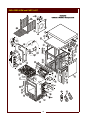
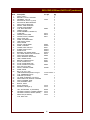
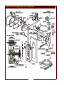
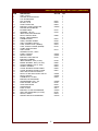
1
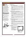
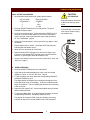
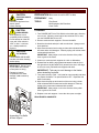
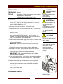
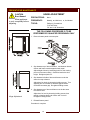
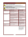
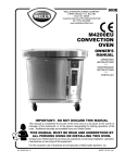
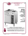
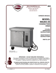
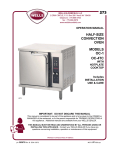
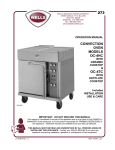
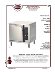
903E
OWNERS MANUAL
MODEL
M4200EU
CONVECTION
OVEN
Includes
OPERATING
INSTRUCTIONS
MAINTENANCE
INSTRUCTIONS
PARTS LIST
Model M4200EU
with optional PREP TOP
IMPORTANT: DO NOT DISCARD THIS MANUAL
This manual is considered to be part of the appliance and is to be given to the OWNER or
MANAGER of the restaurant, or to the person responsible for TRAINING OPERATORS of
this appliance. Additional manuals are available from your WELLS DEALER.
THIS MANUAL MUST BE READ AND UNDERSTOOD BY ALL PERSONS USING OR
INSTALLING THIS APPLIANCE. Contact your WELLS DEALER if you have any
questions concerning installation, operation or maintenance of this equipment.
p/n 305604 Rev.(-) ECN-12475
M903E 022103 cps
GLOBAL WARRANTY STATEMENT
All electrical product manufactured by Wells/Bloomfield are warranted against defects in material and workmanship by our
authorized service provider with:
• One (1) year replacement part warranty
•
•
One (1) year on labor
All genuine Well/Bloomfield replacement parts are warranted for ninety (90) days from date of purchase on
non-warranty equipment. This parts warranty is limited only to replacements of the defective part. Any use of
non-genuine Wells/Bloomfield parts completely voids any warranty.
Labor includes cost of service invoice and travel time is limited to sixty (60) mile radius (or up to a maximum of one hour) to the
nearest authorized service provider. This service will be provided on the customer’s premises for non-portable models. Portable
models (a device with a cord and plug) must be taken or shipped to the closet authorized service provider; transportation charges
prepaid. All labor shall be performed during regular working hours. Overtime premium will be charged to the buyer.
Warranty exclusions:
a) No warranty on glass decanters, airpot liners, or sight glasses for breakage of any kind.
b) Airpots carry thirty (30) day parts replacement only.
c) Dispensers (i.e., tea and coffee) carry ninety (90) day parts replacement only.
d) Warranty does not include any coverage for:
•
•
•
•
•
•
•
•
Resetting the safety thermostats, circuit breakers, overload protectors, or fuse replacements unless
warranted conditions are caused.
All problems due to operation at voltage other than specified on equipment nameplates -- conversion to
correct voltage must be the customer’s responsibility.
All problems due to electrical connections not made in accordance with electrical code requirements and
wiring diagrams supplied with the equipment.
All problems due to inadequate water supply, such as fluctuating, high or low water pressure, etc.
Tank heating element if energized before water tank is filled.
All problems due to mineral/calcium deposits, or contamination from chlorides/chlorines. De-liming is
considered a preventative maintenance function and not covered by warranty.
Calibration of thermostat. Replacement of items subject to normal wear to include such items as knobs,
light bulbs, baskets, grids, mechanical timers, and thermocouples. Normal maintenance functions including
lubrication, adjustment of airflow, thermostats, door mechanisms, microswitches, replacement of fuses, and
indicating light.
Installation, labor, and job check-outs are not considered warranty.
THIS WARRANTY IS THE COMPLETE AND ONLY WARRANTY, EXPRESS OR IMPLIED IN LAW OR FACT, INCLUDING BUT
NOT LIMITED TO WARRANTIES OF MERCHANTABILITY OR FITNESS FOR ANY PARTICULAR PURPOSE, AND/OR FOR
DIRECT, INDIRECT OR CONSEQUENTIAL DAMAGES IN CONNECTION WITH WELL/BLOOMFIELD PRODUCTS. This warranty
is void if it is determined that upon inspection by an authorized Wells/Bloomfield service provider that the equipment has been
modified, misused, misapplied, improperly installed, or damaged in transit or by fire, flood or act of nature. All problems due to water
supply, lime build-up, or high or low water pressure are not covered by this warranty. It also does not apply if the serial nameplate
has been removed or service is performed by unauthorized personnel.
SHIPPING DAMAGE CLAIM PROCEDURE
NOTE: For your protection, please note that equipment in
this shipment was carefully inspected and packaged by
skilled personnel before leaving the factory. Upon
acceptance of this shipment, the transportation company
assumes full responsibility for its safe delivery.
IF SHIPMENT ARRIVES DAMAGED:
1. VISIBLE LOSS OR DAMAGE: Be certain that any
visible loss or damage is noted on the freight bill or
express receipt, and that the note of loss or damage is
signed by the delivery person.
2. FILE CLAIM FOR DAMAGE IMMEDIATELY:
Regardless of the extent of the damage.
3.
CONCEALED LOSS OR DAMAGE: if damage is
unnoticed until the merchandise is unpacked, notify the
transportation company or carrier immediately, and file
“CONCEALED DAMAGE” claim with them. This
should be done within fifteen (15) days from the date
the delivery was made to you. Be sure to retain the
container for inspection.
Wells Manufacturing cannot assume liability for damage or
loss incurred in transit. We will, however, at your request,
supply you with the necessary documents to support your
claim.
xi
TABLE OF CONTENTS
WARRANTY
SPECIFICATIONS
FEATURES & OPERATING CONTROLS
PRECAUTIONS & GENERAL INFORMATION
AGENCY LISTING INFORMATION
INSTALLATION
OPERATION
CLEANING INSTRUCTIONS
PREVENTATIVE MAINTENANCE
Hinge Adjustment
TROUBLESHOOTING SUGGESTIONS
EXPLODED VIEW and PARTS LIST
WIRING DIAGRAM
PARTS & SERVICE
CUSTOMER SERVICE DATA
xi
1
2
4
4
5
8
10
12
13
14
18
19
19
INTRODUCTION
Thank You for purchasing this Wells Manufacturing Co. appliance.
Proper installation, professional operation and consistent maintenance of this appliance will ensure that it
gives you the very best performance and a long, economical service life.
This manual contains the information needed to properly install this appliance, and to use and care for the
appliance in a manner which will ensure its optimum performance.
SPECIFICATIONS
DIMENSIONS
APPLIANCE
OVEN CAVITY
Wide
30-1/8” (765mm)
14-3/8” (365mm)
Deep
25-1/4” (641mm) oven only
27-7/8” (682mm) incl. handle
21” (533mm)
High
25-1/8” (638mm) oven only
34” (863mm) incl. prep-top\
and casters
20” (508mm)
Door Swing
20" (508mm) radius
ELECTRICAL
380-415
L1
L2
L3
N
VAC 3NAC 50/60Hz
11.7 Amps
11.7 Amps
11.7 Amps
0.0 Amps
8400 Watts
1
FEATURES & OPERATING CONTROLS
2
FEATURES & OPERATING CONTROLS (continued)
ITEM DESCRIPTION
FUNCTION
A.
OPTIONAL PREP TOP
Allows top of oven to be used as a work surface
B.
OVEN TOP
Covers and protects top insulation
C.
OVEN DOOR
Covers and provides access to oven cavity
Ergonomic handle is part of the door
D.
LATCH
Holds oven door closed
E.
ACCESS PANEL
Covers and provides access to fan motor and electric
connections and controls
F.
COOLING LOUVERS
Provides air circulation for cooling. DO NOT spray or pour
water into cooling louvers
G.
COOLING FAN OUTLET
Provides ventilation for internal electrical components
H.
EXTERIOR VENT
Replaces louvered biscuit baking adapter plate when oven is
used for cooking protein
J.
OPTIONAL FRONT CASTERS
Allow oven to be easily moved; locking to stabilize oven
when in position
K.
OPTIONAL REAR CASTERS
Allow oven to be easily moved
L.
ELECTRICAL INLET
Electric power supply enters here
M.
AUXILLARY CHASSIS GROUND
Building earth connection
N.
FUSE
Protect electrical circuits from overload
O.
DATA PLATE
Provides manufacturer, model and serial number information.
Also, provides electrical specifications and requirements
P.
HEAT ON LIGHT
Glows amber when heating elements are energized
Q.
ON/OFF/FAN SWITCH
Turns oven and fan, or fan only, on or off
R.
POWER ON LIGHT
Glows green when power is turned on
S.
SOLID STATE CONTROL
Controls cooking times and temperatures; programmable.
DO NOT spray or pour water into controller
T.
BEEPER
Audible indicator for alarms, end-of-cycle, etc.
U.
RACK SUPPORTS
Hold cooking racks
V.
PRODUCT RACK
Holds product to be cooked
W.
HEATING ELEMENTS
Provide cooking heat when energized
X.
FAN
Circulates heated air during cooking
Y.
FAN BAFFLE
Covers fan, also provides mounting for right rack support
3
PRECAUTIONS AND GENERAL INFORMATION
WARNING:
ELECTRIC
SHOCK HAZARD
All servicing requiring
access to non-insulated
electrical components
must be performed by a
factory authorized
technician.
DO NOT open any access
panel which requires the
use of tools. Failure to
follow this warning can
result in severe electrical
shock.
CAUTION:
RISK OF
DAMAGE
DO NOT connect or
energize this appliance
until all installation
instructions are read and
followed. Damage to the
appliance will result if
these instructions are not
followed.
CAUTION:
HOT SURFACE
Exposed surfaces
can be hot to the touch and
may cause burns.
This appliance is intended for use in commercial establishments
only.
This appliance is intended to prepare food for human consumption.
No other use is recommended or authorized by the manufacturer or its
agents.
Operators of this appliance must be familiar with the appliance use,
limitations and associated restrictions. Operating instructions must be
read and understood by all persons using or installing this appliance.
Cleanliness of this appliance is essential to good sanitation. Read and
follow all included cleaning instructions and schedules to ensure the
safety of the food product.
Disconnect this appliance from electrical power before performing any
maintenance or servicing.
DO NOT submerge this appliance in water. This appliance is not jet
stream approved. Do not direct water jet or steam jet at this appliance,
or at any control panel or wiring. Do not splash or pour water on, in or
over any controls, control panel or wiring. Do not wash floor around
this appliance with water or steam jet.
Exposed surfaces of this appliance can be hot to the touch and may
cause burns.
Do not operate this appliance if the control panel is damaged. Do not
operate this appliance if the keypad section of the control panel is torn
or broken. Call your Authorized Wells Service Agent for service.
The technical content of this manual, including any wiring diagrams,
schematics, parts breakdown illustrations and/or adjustment
procedures, is intended for use by qualified technical personnel.
Any procedure which requires the use of tools must be performed by a
qualified technician.
This manual is considered to be a permanent part of the appliance.
This manual and all supplied instructions, diagrams, schematics, parts
breakdown illustrations, notices and labels must remain with the
appliance if it is sold or moved to another location.
This appliance is made in the USA. Unless otherwise noted, this
appliance has American sizes on all hardware.
AGENCY LISTING INFORMATION
STD 4
This appliance conforms to NSF Standard 4 for sanitation only if
installed in accordance with the supplied Installation Instructions and
maintained according to the instructions in this manual.
This appliance meets
4
requirements.
INSTALLATION
UNPACKING & INSPECTION
Carefully remove the appliance from the carton. Remove all
protective plastic film, packing materials and accessories from the
Appliance before connecting electrical power or otherwise performing
any installation procedure.
Carefully read all instructions in this manual and the Installation
Instruction Sheet packed with the appliance before starting any
installation.
Read and understand all labels and diagrams attached to the
appliance.
Carefully account for all components and accessories before
discarding packing materials. Store all accessories in a convenient
place for later use.
COMPONENTS
3 ea.
2 ea.
1 ea.
1 ea.
NOTE: DO NOT discard
the carton or other packing
materials until you have
inspected the appliance for
hidden damage and tested it
for proper operation.
Refer to SHIPPING DAMAGE
CLAIM PROCEDURE on the
inside front cover of this
manual.
WARNING:
RISK OF
PERSONAL INJURY
Installation procedures must
be performed by a qualified
technician with full knowledge
of all applicable electrical and
plumbing codes. Failure can
result in personal injury and
property damage.
OVEN RACKS
RACK SUPPORTS
FAN BAFFLE
VENT DUCT ASSEMBLY
ACCESSORIES
1 ea. LITERATURE PACKAGE
SERVICE TECHNICIAN INSTALLATION NOTES
1. Installation and start up should be performed by an authorized
installation company.
2. Verify that this equipment installation is in compliance with the
specifications listed in this manual and with local code
requirements.
5
IMPORTANT:
It is the RESPONSIBILITY
OF THE INSTALLER to
check with the AUTHORITY
HAVING JURISDICTION, in
order to verify compliance
with local codes and
ordinances for THIS
SPECIFIC EQUIPMENT
INSTALLATION.
INSTALLATION (continued)
WARNING:
EQUIPMENT SET-UP
ELECTRIC
SHOCK HAZARD
1. CURB or COUNTER MOUNTING
a. Setup the appliance only on a firm, level, non-combustible
surface. Verify local codes for requirements. Concrete, tile,
terrazzo or metal surfaces are recommended. Metal over
combustible material may not meet code for non-combustible
surfaces.
b. Appliance is designed for installation with zero clearance at
bottom on non-combustible surfaces only.
c. Recommend at least 3” clearance on sides and back to allow
adequate air flow.
All servicing requiring
access to non-insulated
electrical components must
be performed by a factory
authorized technician.
DO NOT open any access
panel which requires the
use of tools. Failure to
follow this warning can
result in severe electrical
shock.
NOTE: Oven is shipped with
louvered biscuit baking
adapter plate attached to rear
panel.
If oven is used exclusively for
bread products (bread, pies,
etc.), DO NOT remove
adapter.
If oven is used for proteins,
remove adapter and install
external vent. Protein
requires additional venting to
decrease release of cooking
vapors when opening the
door.
Vent Duct Installation
2. INSTALLING OPTIONAL CASTERS (NOTE: Casters are not
provided and must be purchased separately.)
a. Install casters, one on each corner of the appliance, in the
holes provided. Locking casters must be installed on the
FRONT of the appliance.
b. Set up the appliance only on a firm, level, non-combustible
surface. Verify local codes for requirements. Concrete, tile,
terrazzo or metal surfaces are recommended. Metal over
combustible material may not meet code for non-combustible
surfaces.
c. LEVELING: Verify that the appliance sits firmly on all four
casters when in its normal operational position. With a spirit
level, check that the appliance is level front-to-back and
side-to-side.
3. INSTALLING OPTIONAL LEGS (NOTE: Legs are not provided
and must be purchased separately.)
a. Install adjustable legs, one on each corner of the appliance, in
he holes provided.
b. Set up the appliance only on a firm, level, non-combustible
surface. Verify local codes for requirements. Concrete, tile,
terrazzo or metal surfaces are recommended. Metal over
combustible material may not meet code for non-combustible
surfaces.
c. LEVELING: Verify that the appliance sits firmly ON ALL FOUR
LEGS. With a spirit level, check that the appliance is level
front-to-back and side-to-side.
4. INSTALLING ON FABRICATED
MOUNTING
a. Mounting must be capable of
safely supporting 350 pounds
(165 Kg.), and must be
fabricated to the dimensions
shown at right:
b. Attach the appliance securely
to the mounting with four
3/4”-10 x 1” (SAE) bolts.
DIMENSIONS
Fabricated Mounting
6
INSTALLATION (continued)
DANGER: ELECTRICAL SHOCK HAZARD
ELECTRICAL CONNECTIONS MUST BE MADE BY A
LICENSED ELECTRICIAN
Electrical shock will cause death or serious injury.
Refer to the nameplate on the front of the appliance.
• Verify the ELECTRICAL SERVICE POWER.
• Voltage and phase must match the nameplate specifications, and
available electrical service amperage must meet or exceed the
specifications listed on page 1.
• Wiring must be no less than 1.5 mm solid copper wire, rated for at
least 90ºC.
Wire gauge, insulation type and temperature rating , as well as type,
size and construction of conduit, must meet or exceed applicable
specifications of local electrical codes.
The EARTH ground lug is inside the right side access panel, and must
be connected to a suitable earth ground. The POTENTIAL ground
connection is on the back of the cabinet, and must be connected to
other electrical appliances in the room.
CAUTION:
RISK OF
DAMAGE
DO NOT connect or energize
this appliance until all
installation instructions are
read and followed. Damage
to the appliance will result if
these instructions are not
followed.
CAUTION:
ELECTRICAL
SHOCK HAZARD
The ground lug of this
appliance must be connected
to a suitable building ground.
IMPORTANT:
Contact a licensed electrician
to install and connect
electrical power to the
appliance.
IMPORTANT:
Damage due to being
connected to the wrong
voltage or phase is NOT
covered by warranty.
The appliance is shipped from the factory wired for 380-415 volt
3-phase plus Neutral and Ground electrical service.
IMPORTANT: This appliance is designed for 3ø operation only.
7
OPERATION
CAUTION:
SET TEMPERATURE
HOT SURFACE
1. Make sure the power cord is plugged into the appropriate power
supply receptacle.
Exposed surfaces can be hot
to the touch and may cause
burns.
2. Place the ON/OFF/FAN switch in the ON position.
NOTE: No display will be present until the TEMP key is pressed.
3. Press the TEMP key momentarily to display the current oven
temperature. The display will hold for 5 seconds.
4. Press the TEMP button and hold for 3 seconds. The current set
temperature will display and flash. The controller is now in the
programming mode.
5. Use the 3 SET keys to set hundreds, tens and ones for the
desired oven set temperature. The corresponding digit on the
digital readout will increase from 0 to 9. Release the SET key
when the desired digit is displayed.
6. Press the TEMP key to exit the programming mode. The new
set temperature will automatically be stored in memory.
IMPORTANT: Failure to
press the TEMP key within 30
seconds of programming the
new oven set temperature will
cause the controller to revert
to original temperature setting
and delete latest
changes.
7. The maximum temperature to which the controller can be
programmed is 500ºF (260ºC). Any attempt to set the oven
temperature higher than 500ºF (260ºC) will cause the controller to
reset the temperature to 500ºF (260ºC).
NOTE: The "actual temperature" displayed may read higher than set
point during pre-heat until oven temperature has stabilized.
SET TIMER
1. Place the ON/OFF/FAN switch in the ON position.
2. In the IDLE mode, the digital timer displays will be at “low”
intensity, and will brighten while active and counting down.
Verify that the time being displayed on each of the timer digital
displays is correct. If not, proceed as follows:
3. Example: Set TIMER 1
With the timer in IDLE mode (low intensity, not counting down)
a. Press and hold TIMER key 1 and SET key for ONES.
The right digit of timer display 1 will brighten and begin to cycle
through 0 to 9. Release both keys when the desired digit is
reached.
b. Press and hold TIMER key 1 and SET key for TENS.
The left digit of timer display 1 will brighten and begin to cycle
through 0 to 9. Release both keys when the desired digit is
reached. When the keys are released, the display will return
to IDLE mode and the new settings will be retained in memory.
4. TIMER keys 2 through 6 may be set in the same manner.
8
OPERATION (continued)
DAILY SET-UP PROCEDURES
CAUTION:
1. Recommended shelf positions for quality baked products:
HOT SURFACE
NO. OF PANS
OF PRODUCT
1
2
3
RACK POSITION
UTILIZED
5
2&8
2, 5 & 8
2. Place the ON/OFF/FAN switch in the ON position. The green
POWER ON light will glow.
3. Check oven set temperature. Press and hold the TEMP key for 5
seconds or until the screen flashes the current set temperature.
If this is not right, refer to and follow the step-by-step procedure
for ”Set Temperature”, page 8.
4. If the oven set temperature is correct, press the key again to clear
the display.
5. Ensure that the door is closed. The amber HEAT light will glow,
indicating that the heaters are on.
6. Allow the oven to preheat for 30 minutes.
7. When the amber HEAT light goes out, the oven is ready to use.
From then on the amber HEAT light will cycle on and off with the
heaters (i.e. light will glow when the heaters are on).
8. Check to see that the timers are set for the correct times. If not, see
“Set Timer”, page 8.
D.
OVEN OPERATION
1. Place the ON/OFF/FAN switch in the ON position.
2. Verify that the time being displayed on each of the timer digital
displays is correct. If not, see “Set Timer”, page 8.
3. To start a product cook timer, press the corresponding PRODUCT
COOKING TIMER key once.
The digital display will brighten and a timing dot will appear in the
lower right-hand corner of the display. The timer will automatically
begin to countdown. The timer display will show the time remaining
in the cook cycle.
4. When the timer reaches “00”, a three-tone audible alarm will sound,
and the display will blink.
5. To stop the audible alarm, or to cancel a timer operation, press the
corresponding PRODUCT COOKING TIMER key once.
The display will change to IDLE mode (low intensity), the timing
indicator dot will turn off, and the audible tone will be cancelled.
9
Exposed surfaces can be hot
to the touch and may cause
burns.
SUGGESTION: The product
timer can be used for timing
the preheat time.
CLEANING INSTRUCTIONS
CAUTION:
PREPARATION Allow oven to cool to 65ºC or less
ELECTRIC SHOCK
HAZARD
FREQUENCY
Daily
TOOLS
Fiber Brush,
Mild Detergent, McD Sanitizer,
Clean Towel
Disconnect appliance from
electric power
before cleaning.
CAUTION:
BURN HAZARD
Allow appliance to cool
completely before cleaning.
Do not attempt to clean the
oven until it has cooled to
150ºF or less. It can burn
you. Hand protection is
required.
CAUTION:
CUT HAZARD
FAN BLADES ARE SHARP.
Use due care when cleaning
and/or wiping.
IMPORTANT: DO NOT spill
or pour water into controls,
control panel or wiring.
Damage to internal
components from water
damage is not covered by
warranty.
CLEANING
1. Turn POWER SWITCH to FAN. With the door held open, allow the
oven to cool. When the oven interior has cooled to 65ºC or less,
turn the POWER SWITCH to OFF.
2. Remove racks and rack supports. Remove fan baffle.
3. Brush the fan wheel and wipe it with a moist cloth. Sponge out all
loose particles.
4. Wipe down the entire interior using a clean cloth moistened with
hot water and a mild detergent. Rinse by wiping with a clean towel
moistened with sanitizer.
IMPORTANT: Always wipe or rub in the direction of the polish
lines or grain of the metal.
5. Clean oven racks and rack supports in a sink or dishwasher.
6. Reinstall the fan baffle, paying particular attention that the lip on
the right side of the fan baffle is fully seated in the slot in the edge
of the oven cavity. Reinstall rack supports and racks.
IMPORTANT: Take care to avoid damage to fan blades
when reinstalling fan baffle.
7. Turn power switch to FAN . Verify that fan runs smoothly and does
not contact fan baffle. Turn power switch to OFF. Reposition fan
baffle if necessary.
8. Wipe down the prep top and exterior of the oven using a clean
cloth moistened with hot water and a mild detergent. Rinse by
wiping with a clean towel moistened with sanitizer.
IMPORTANT: Always wipe or rub in the direction of the polish
lines or grain of the metal.
9. Replace oven rack supports. Leave the door open overnight.
PROCEDURE IS COMPLETE
Assembling Fan Baffle
& Rack Support
10
CLEANING INSTRUCTIONS (continued)
PREPARATION Allow oven to cool to 65ºC or less
CAUTION:
FREQUENCY
Weekly
ELECTRIC SHOCK
HAZARD
TOOLS
Fiber Brush, Plastic Scouring Pad, Plastic Scraper
Mild Detergent, McD Sanitizer,
APC All Purpose Cleaner, Clean Towel
CLEANING
Disconnect appliance from
electric power
before cleaning.
CAUTION:
1. Turn POWER SWITCH to FAN. With the door held open, allow the
oven to cool. When the oven interior has cooled to 65ºC or less,
turn the POWER SWITCH to OFF.
2. Remove racks and rack supports. Remove fan baffle.
3. Brush the fan wheel and wipe it with a moist cloth. Sponge out all
loose particles.
4. Scrub entire interior of convection oven with a plastic scouring pad
and APC cleaner.
5. For baked-on food spills, apply APC cleaner. Close the oven
door, place the ON/OFF/FAN switch in the OFF position. Let
stand for 10 minutes. Carefully wipe all cleaner and food residue
from all interior surfaces. Wipe with sanitizer.
6. Wipe down the entire interior using a clean cloth or moistened with
hot water and a mild detergent. Rinse by wiping with a clean towel
moistened with sanitizer.
IMPORTANT: Always wipe or rub in the direction of the polish
lines or grain of the metal.
7. Clean oven racks and rack supports in a sink or dishwasher.
8. Reinstall the fan baffle, paying particular attention that the lip on
the right side of the fan baffle is fully seated in the slot in the edge
of the oven cavity. Reinstall rack supports and racks.
BURN HAZARD
Allow appliance to
cool completely before
cleaning.
Do not attempt to clean the
oven until it has cooled to
150ºF or less. It can burn
you. Hand protection is
required.
CAUTION:
CUT HAZARD
FAN BLADES ARE SHARP.
Use due care when cleaning
and/or wiping.
IMPORTANT: DO NOT spill
or pour water into controls,
control panel or wiring.
Damage to internal
components from water
damage is not covered by
warranty.
IMPORTANT: Take care to avoid damage to fan blades
when reinstalling fan baffle.
9. Turn power switch to FAN . Verify that fan runs smoothly and does
not contact fan baffle. Turn power switch to OFF. Reposition fan
baffle if necessary.
10. Wipe down the prep top and exterior of the oven using a clean
cloth moistened with hot water and a mild detergent. A plastic
scouring pad may be used to removed baked-on food debris.
Rinse by wiping with a clean towel moistened with sanitizer.
IMPORTANT: Always wipe or rub in the direction of the polish
lines or grain of the metal.
11. Replace oven rack supports. Leave the door open overnight.
PROCEDURE IS COMPLETE
Assembling Fan Baffle
& Rack Support
11
PREVENTATIVE MAINTENANCE
CAUTION:
Burn Hazard
Allow appliance
to cool completely before
adjusting.
HINGE ADJUSTMENT
PRECAUTIONS:
None
FREQUENCY:
Monthly, at a Minimum; or, As Needed
TOOLS:
Phillips (+) Screwdriver
7/16" Nut Driver
7/8" and 1-1/8" Wrenches
THE FOLLOWING PROCEDURE IS TO BE
PERFORMED BY QUALIFIED PERSONNEL ONLY
1. Remove bottom panel to access pivot.
2. Gap between top of door and frame , and between bottom
of door and frame must be approximately equal
Adjust height of door by loosening jamb nut, then turning
pivot on its screw mounting. Clockwise lowers the door
height. Re-tighten jamb nut .
3. Gap between left side of door and frame must be the
same from top to bottom
Adjust door for plumb by loosening holding screws. Turn
adjusting bolt to increase or decrease gap at bottom.
Clockwise increases gap. Re-tighten holding screws.
4. Gap between top of door and frame must be the same
from side to side
Hinge Adjustment
Adjust door for level by loosening holding screws, then
raising or lowering latch-end of door until it is level.
Re-tighten holding screws.
5. Reinstall bottom panel.
Procedure is complete
12
TROUBLESHOOTING SUGGESTIONS
CAUTION: Electrical Shock Hazard
Removal of any cabinet panel will result in exposed electrical circuits.
Any procedure requiring the removal of any cabinet panel must be performed
by a qualified technician only.
CAUTION: Electrical Shock Hazard
Fuse replacement may expose dangerous voltages.
Fuse replacement must be performed by a qualified technician.
SYMPTOM
POSSIBLE CAUSE
SUGGESTED REMEDY
No power to appliance
Circuit breaker off or tripped
Reset circuit breaker
Fuse blown or loose
Check power fuses. If blown,
correct problem and replace
fuses
Power switch turned to OFF or FAN
Turn power switch ON
Temperature control not set
Set to desired temperature
Oven door not closed
Be sure door is closed and
latched
Hi-limit control tripped on excessive
oven temperature
Allow oven to cool
Hi-limit will reset
Damaged controller
Contact Authorized Wells
Service Agency for repairs
Fan switch OFF
Turn fan switch to HIGH or
LOW
Damage to internal components
Contact Authorized Wells
Service Agency for repairs
Latch out of adjustment
Adjust latch
Oven will not heat
Blower fan will not run
Door pops open during
cook cycle
NOTE: There are no user
serviceable components in the
appliance. In all cases of
damage or component
malfunction, contact your
Authorized Wells Service
Agency for repairs.
13
EXPLODED VIEW and PARTS LIST
14
EXPLODED VIEW and PARTS LIST (continued)
item
1
13
14
15
16
17
19
20
21
22
29
30
35
36
39
40
42
44
46
47
50
51
52
54
55
57
58
59
60
68
69
80
83
84
88
89
90
92
94
95
96
101
102
103
A
B
C
description
ASSY, CAVITY
BRACKET, CAVITY SUPPORT
GROMMET, 7/8" O.D.
INSULATION, CAVITY (7 parts)
INSULATION, MOTOR MOUNT
ASSY, BAFFLE SUPPORT
MOUNT, TEMP SENSORS
COVER, DOOR GASKET
CLIP, RACK SUPPORT
HANDLE, DOOR
DOOR ASSEMBLY, RETRO KIT,
COMPLETE
GASKET, DOOR, SIDE
GASKET, DOOR, TOP/BOT
ASSY, OVEN TOP
PANEL, EXTERIOR SIDE
TRIM, RIGHT FRONT
ASSY, FRAME
SLEEVE, DOOR HINGE
PANEL, CONTROL
GUARD, PROX. SWITCH
STRIKE, DOOR LATCH
DOOR LATCH
BUSHING, TOP DOOR HINGE
PIN, HINGE, DOOR TOP & BOTTOM
ASSY, BOT DOOR HINGE
ASSY, INTERNAL VENT DUCT
TRIM, LOWER FRONT
BRACKET, PROX SWITCH
PLATE, DOOR PIVOT
PLATE, DOOR HINGE PIN
PLATE, DOOR PIVOT HOLE
NUT, HEX 3/4-10 UNC
DECAL, CONTROL PANEL
PANEL, REAR
BOLT, 3/4-10 x 1 HEX
(TABLE MOUNTING) Refer to Page 6.
CLIP, TINNERMAN (pk 50)
WIRE SET (not shown)
TIE, WIRE, STANDOFF (not shown)
ADA PTER PLATE, BISCUIT COOKING
ASSY, EXTERNAL VENT
CAP, EXTERNAL VENT
BAFFLE, OVEN
RACK, PRODUCT
SUPPORT, RACK (pk 2)
LEG, ADJUSTABLE, 6" (OPTIONAL)
OPTIONAL CASTER, LOCKING (FRONT)
OPTIONAL CASTER, SWIVEL (REAR)
PREP TOP (OPTIONAL)
CLIP, PREP TOP
svc p/n
51040
63889
22914
63819
63817
63900
503297
65647
505616
505615
505619
63912
63896
63804
63787
63899
63899
503285
qty
1
2
2
1
1
2
1
4
8
1
1
2
2
1
2
1
1
1
1
1
1
1
1
1
1
1
1
1
1
2
1
1
1
1
Local Purchase 4
57943
1
2
1
1
1
1
21376
3
21375
2
65598
21373
21372
21445
15
4
2
2
1
4
EXPLODED VIEW and PARTS LIST (continued)
16
EXPLODED VIEW and PARTS LIST (continued)
ITEM
1
3
4
5
7
7.1
7.2
8
9
14
16
18
19
26
28
31
33
37
38
42
45
46
49
59
61
62
63
64
70
71
72
73
74
75
76
77
78
79
81
82
85
86
87
89
97
DESCRIPTION
ASSY, CAVITY
SPACER, BLOWER MOTOR
LUG, SOLDERLESS
FAN, COOLING
MOTOR, 1/4 HP
START CAPACITOR
BRACKET, START CAPACITOR
SPACER, MOTOR MOUNT
BLOWER WHEEL
GROMMET, 7/8" O.D.
INSULATION, MOTOR MOUNT
RELAY, 208/240V SPNO
MOUNT, TEMP SENSORS
THERMOCOUPLE
LABEL, GROUND SYMBOL
ASSY, PROXIMITY SWITCH
LIGHT, SIGNAL "HEAT" (AMBER)
LIGHT, SIGNAL "POWER" (GREEN)
CLAMP, WIRE HOLDING
ASSY, FRAME
TERMINAL BLOCK, 4 POLE
PANEL, CONTROL
SWITCH ON/OFF
BRACKET, PROX SWITCH
BRACKET, ELEMENT
INNER ELEMENT, 240V (4" GAP)
MIDDLE ELEMENT, 240V (2.5" GAP)
OUTER ELEMENT, 240V (1" GAP)
GASKET, ELEMENT
COVER, ELEMENT GASKET INNER
COVER, ELEMENT GASKET OUTER
HEAT SINK, SOLID STATE RELAY
RELAY, 55 AMP SOLID STATE 230V 3ø
RELAY, 220/240V
THERMOSTAT, HI-LIMIT
BRACKET, MOTOR MOUNT
TRANSFORMER, 240V - 18V
FUSE HOLDER, 10A 240V
OVEN CONTROLER
STRAIN RELIEF
FUSE, 5A 240V
BRACKET, HI-LIMIT THERMOBULB
HEAT SINK COMPOUND (not shown)
SWITCH, ON/OFF
QUENCH-ARC RFI SUPPRESSOR
SVC P/N
64687
63932
69823
500933
63797
51040
63880
63927
64584
65239
50516
65146
69775
503297
503287
63787
63783
63800
63949
63834
63836
63837
503281
503284
63933
503286
83785
64964
500102
54871
503303
66160
63918
505160
17
QTY
1
4
1
1
1
1
1
4
1
2
1
1
1
1
1
1
1
1
1
1
1
1
1
1
6
1
1
1
1
1
1
1
1
1
1
1
1
1
1
1
1
1
1
1
1
WIRING DIAGRAM
18
PARTS & SERVICE
DESCRIPTION
PART NO.
CASTER SET, OVEN (set of 4)
OVEN STACKING KIT
CASTER, SWIVEL (set of 2)
CASTER, LOCKING (set of 2)
OVEN RACK, REPLACEMENT (ea.)
PREP TOP
WALL SPACER KIT
LEG KIT, OVEN, S/S (set of 4)
VENTING & STACKING KIT
21330
21342
21372
21373
21376
21445
21717
22226
22682
IMPORTANT: Use only
factory authorized service
parts and replacement
filters.
For factory authorized
service, or to order factory
authorized replacement
parts, contact your Wells
authorized service agency,
or call:
Wells Manufacturing Co.
2 Erik Circle
P. O. Box 280
Verdi, NV 89439
phone: (775) 689-5700
fax:
(888) 492-2783
(Service Parts Dept.)
Service Parts Department
can supply you with the
name and telephone
number of the WELLS
AUTHORIZED SERVICE
AGENCY nearest you.
CUSTOMER SERVICE DATA
please have this information available if calling for service
RESTAURANT _____________________________ LOCATION _____________
INSTALLATION DATE ________________________ TECHNICIAN ___________
SERVICE COMPANY ________________________________________________
ADDRESS ___________________________ STATE ______ ZIP__________
TELEPHONE NUMBER (_____)_____-_________
EQUIPMENT MODEL NO. _______________
EQUIPMENT SERIAL NO. _______________
VOLTAGE:
380-415 VAC
19
PREPARED FOR
BY