1
Discipline
Engineering Standard –NSW
Category
Signalling
Title
Cerberus Level Crossing Monitor Equipment
Reference Number
SMS 02 –(RIC Standard: SC 01 51 00 00 EQ)
Document Control
Status
Issue 1
Revision 2
Date
Prepared
Reviewed
Endorsed
Approved
Standards and
Systems
Standards
Engineer
GM
Infrastructure
Strategy &
Performance
Safety
Committee
Refer to
Reference
Number
H Olsen
M Owens
Refer to minutes
of meeting
12/08/04
Mar 05
Engineering Standard –NSW
Signalling
Cerberus Level Crossing Monitor Equipment
SMS 02
Disclaimer
Australian Rail Track Corporation has used its best endeavors to ensure that the content,
layout and text of this document is accurate, complete and suitable for its stated purpose. It
makes no warranties, express or implied, that compliance with the contents of this document
shall be sufficient to ensure safe systems of work or operation. Australian Rail Track
Corporation will not be liable to pay compensation in respect of the content or subsequent
use of this document for any other purpose than its stated purpose or for any purpose other
than that for which it was prepared except where it can be shown to have acted in bad faith
or there has been willful default.
Document Approval
The technical content of this document has been approved by the relevant ARTC
engineering authority and has also been endorsed by the ARTC Safety Committee.
Document Supply and Control
The Primary Version of this document is the electronic version that is available and
accessible on the Australian Rail Track Corporation Internet and Intranet website.
It is the document user’
ssol
er
es
ponsi
bi
l
i
t
yt
oensur
et
hatcopi
esar
echeckedf
orcur
r
ency
against the Primary Version prior to its use.
Copyright
The information in this document is Copyright protected. Apart from the reproduction without
alteration of this document for personal use, non-profit purposes or for any fair dealing as
permitted under the Copyright Act 1968, no part of this document may be reproduced,
altered, stored or transmitted by any person without the prior written consent of ARTC.
March 2005
Version 1.2
© Australian Rail Track Corporation
This document is uncontrolled when printed.
Page 2 of 118
Engineering Standard –NSW
Signalling
Cerberus Level Crossing Monitor Equipment
SMS 02
About This Publication
This document provides information for the maintenance of SCADA-2000
Cerberus Level Crossing monitors.
This document is primarily intended to be read by staff involved with the
testing, commissioning and maintenance of the Level Crossing monitor
equipment.
The‘
Cer
ber
us’l
ev
elcr
ossi
ngmoni
t
or
,moni
t
or
st
hest
at
usofar
ai
l
wayl
ev
el
crossing warning system, logs events, reports warning or failure conditions
to a central location (Control Centre), and provides facilities to remotely
test the level crossing battery supply. In typical installations the following
items are monitored and logged (some also have alarms): track circuits,
control relays, level crossing warning lamps, flasher units, power supplies,
batteries, associated signal control relays. The event logging retains the
last 10,000 changes to; relay positions, analogue voltage changes and to
changes in the number of operating lamps. Typically this is equivalent to
150 crossing operations.
The level crossing monitor is designed and interfaced to the level crossing
equipment in such a way as to minimise the risk of it providing incorrect
information in a manner that is not obviously incorrect or reducing the
integrity of the level crossing.
The level crossing monitor has been especially designed to be interfaced
with Signal Engineering standard signalling designs which are used
throughout NSW. (See standard signalling circuits in appendix C).
Maintenance staff can visit the level crossing monitor and download the
l
oggedi
nf
or
mat
i
onandt
heuni
t
’
sst
at
usvia a PC and serial cable or they
can obtain the same information remotely via modem from a remote site.
If the optional Control Centre system is implemented then the Control
Centre automatically interrogates the level crossing monitor sites and
conducts battery tests. This Control Centre provides a automatic
monitoring and checking system for a number of level crossing monitors.
March 2005
Version 1.2
© Australian Rail Track Corporation
This document is uncontrolled when printed.
Page 3 of 118
Engineering Standard –NSW
Signalling
Cerberus Level Crossing Monitor Equipment
SMS 02
Document History
Primary Source –ARTC Standard SC 01 51 00 00 EQ Version 3.0
List of Amendments –
ISSUE
DATE
1.1
1.2
01/09/2004
14/03/2005
March 2005
Version 1.2
CLAUSE
Disclaimer
DESCRIPTION
Reformatting to ARTC Standard
Minor editorial change
© Australian Rail Track Corporation
This document is uncontrolled when printed.
Page 4 of 118
Engineering Standard –NSW
Signalling
Cerberus Level Crossing Monitor Equipment
SMS 02
Table of Contents
1. Introduction ...........................................................................................................10
1.1 Referenced and Associated publications ......................................10
1.2 Definitions .....................................................................................10
2. Overview ................................................................................................................10
2.1 Monitoring (How does it operate?) ................................................10
2.2 Control and Interrogation ..............................................................13
2.3 Logging .........................................................................................14
2.4 Status Reporting ...........................................................................14
2.4.1 General ..................................................................................14
2.4.2 Maintenance disable of Status Reporting ...............................15
2.4.3 Codes reported to Control Centre ..........................................15
2.5 Digital Inputs .................................................................................16
2.6 Digital Outputs ..............................................................................17
2.7 Analogue inputs ............................................................................18
2.8 Battery Testing .............................................................................19
2.9 Configuration ................................................................................20
3. Operation and Functional Checks .......................................................................21
3.1 General .........................................................................................21
3.2 Main Box ......................................................................................23
3.2.1 General ..................................................................................23
3.2.2 SCADA 2000 A I/O Board ......................................................23
3.2.3 Power Supply Units (PSU) .....................................................29
3.2.4 Analogue to Digital Converter (ADC) ......................................31
3.2.5 Backplane ..............................................................................32
3.3 Current sensor ..............................................................................34
3.3.1 Description .............................................................................34
3.3.2 Function .................................................................................35
3.3.3 Operation ...............................................................................35
3.3.4 Configuration and Set-up .......................................................35
3.3.5 Troubleshooting ......................................................................36
3.3.6 Replacement ..........................................................................37
3.4 VIO ...............................................................................................37
3.4.1 Description .............................................................................37
March 2005
Version 1.2
© Australian Rail Track Corporation
This document is uncontrolled when printed.
Page 5 of 118
Engineering Standard –NSW
Signalling
Cerberus Level Crossing Monitor Equipment
SMS 02
3.4.2 Function ................................................................................. 38
3.4.3 Operation ............................................................................... 38
3.4.4 Configuration and Set-up ....................................................... 38
3.4.5 Troubleshooting ...................................................................... 38
3.4.6 3.4.6 Replacement ................................................................. 39
3.5 Input Optoisolator ......................................................................... 39
3.5.1 Description ............................................................................. 39
3.5.2 Function ................................................................................. 40
3.5.3 Operation ............................................................................... 40
3.5.4 Troubleshooting ...................................................................... 41
3.5.5 Replacement Procedure ......................................................... 42
3.6 Output Optoisolator ...................................................................... 43
3.6.1 Description ............................................................................. 43
3.6.2 Function ................................................................................. 44
3.6.3 Operation ............................................................................... 44
3.6.4 Configuration .......................................................................... 45
3.6.5 Troubleshooting ...................................................................... 45
3.6.6 Multiple Output Failures On One Board ................................. 45
3.6.7 Replacement Procedure ......................................................... 48
3.7 Cables .......................................................................................... 48
3.8 Modem ......................................................................................... 49
3.8.1 DPX-223 Modem .................................................................... 50
3.8.2 DPX-213 Modem .................................................................... 50
3.8.3 DPX-224 Modem .................................................................... 51
3.8.4 Maestro Executive 144FM Modem ......................................... 51
3.8.5 Modem Replacement ............................................................. 51
3.8.6 Other Brand Modems ............................................................. 52
3.9 Telephone line .............................................................................. 52
3.10 Interface Relays and Timer ........................................................ 52
3.11 Battery test resistor ..................................................................... 55
3.12 Signage for Remote Battery Test Sites ...................................... 55
4. Systems Maintenance Program ........................................................................... 57
4.1 Maintenance Tasks ...................................................................... 57
4.1.1 Corrective Maintenance ......................................................... 57
4.1.2 Preventative Maintenance ...................................................... 57
4.1.3 EPROM Replacement or Configuration Data Change............. 57
March 2005
Version 1.2
© Australian Rail Track Corporation
This document is uncontrolled when printed.
Page 6 of 118
Engineering Standard –NSW
Signalling
Cerberus Level Crossing Monitor Equipment
SMS 02
4.1.4 Interrogating the Monitor ........................................................ 59
4.2 Tools and Maintenance ................................................................ 65
4.3 Maintenance Instructions .............................................................. 65
4.4 Incident Investigation .................................................................... 66
5. Fault Diagnosis ..................................................................................................... 67
5.1 General ......................................................................................... 67
5.2 Faults reported by Operations ...................................................... 68
5.3 Faults Detected during Maintenance ............................................ 69
5.3.1 Monitor does not report a status change ................................ 69
5.3.2 Changes are not appearing in the log .................................... 69
5.3.3 Lamp Learn does not complete within 40 seconds ................ 69
5.3.4 Lamp Learn rejects the results ............................................... 70
5.3.5 Lamp problem detected while Crossing operating ................. 71
5.3.6 Lamp problem detected while Crossing not operating ............ 72
5.3.7 Battery test does not work ...................................................... 72
5.3.8 Monitor indicates a Fault ........................................................ 72
5.3.9 Monitor indicates a SYS Fault ................................................ 72
5.3.10 Monitor indicates a Warning ................................................. 73
5.3.11 Unable to communicate with the monitor locally .................. 73
5.3.12 Unable to communicate with the monitor remotely ............... 74
5.3.13 LEDs on the SCADA card not behaving normally ................ 74
5.3.14 Monitor restarting unexpectedly ........................................... 74
5.3.15 Clock stopped or showing invalid time ................................. 74
6. Installation ............................................................................................................. 75
6.1 Circuit Design considerations ....................................................... 75
6.1.1 General .................................................................................. 75
6.1.2 Battery Test Outputs .............................................................. 76
6.1.3 Battery Test Relay .................................................................. 76
6.1.4 Non-Vital Timer ...................................................................... 76
6.1.5 Test Load Resistor ................................................................. 76
6.2 Equipment Installation .................................................................. 77
6.3 Hardware Configuration ............................................................... 77
6.4 Commissioning Procedure ........................................................... 78
7. Data Configuration ............................................................................................... 82
7.1 Configuration Data Description ..................................................... 82
7.1.1 Scope of data ......................................................................... 82
March 2005
Version 1.2
© Australian Rail Track Corporation
This document is uncontrolled when printed.
Page 7 of 118
Engineering Standard –NSW
Signalling
Cerberus Level Crossing Monitor Equipment
SMS 02
7.1.2 Permanent Configuration data syntax ..................................... 82
7.1.3 Variable configuration data ..................................................... 91
7.2 Customising Generic expressions ................................................ 93
7.3 Data Generation ........................................................................... 95
7.4 EPROM programming .................................................................. 95
8. Log Interpretation ................................................................................................. 98
8.1 General ........................................................................................ 98
8.2 Log entry types ............................................................................ 99
8.2.1 Digital inputs and Outputs ....................................................... 99
8.2.2 Intermediate variables ............................................................. 99
8.2.3 Timers ..................................................................................... 99
8.2.4 Analogue ............................................................................... 100
8.2.5 Connection status ................................................................. 102
8.3 Analysis ...................................................................................... 102
8.4 Spurious events ......................................................................... 103
9. Hardware Repair/Replacement .......................................................................... 103
March 2005
Version 1.2
© Australian Rail Track Corporation
This document is uncontrolled when printed.
Page 8 of 118
Engineering Standard –NSW
Signalling
Cerberus Level Crossing Monitor Equipment
1.
1.1
SMS 02
Introduction
Referenced and Associated publications
The following Signal Engineering Specifications provide additional
information to this document.
Specification 1033
Vital Indication Optoisolator.
Specification 1068
Analogue to Digital Converter
Specification 1069
Current sensor.
Specification 1070
Level Crossing Monitor Requirements
Specification 1071
Level crossing monitor hardware
Specification 1072
Level Crossing monitor - backplane.
Specification 1073
Optoisolator
Scada 2000 D12 - Individual Input
Specification 1074
8 way output optoisolator
The following Signal Engineering manuals provide additional
information to this document.
Cerberus Control Centre users guide
SCADA 2000 A/2.0 Technical
manual.
1.2
Definitions
The following mnemonics are used in this document.
2.
2.1
ADC
Analogue to Digital Converter
IIO
Individual Input Optoisolator
PCB
Printed Circuit Board
SCADA
Supervisory Control And Data Acquisition
VIO
Vital Indication Optoisolator
Overview
Monitoring (How does it operate?)
Onceev
er
y0.
25sec
ondst
heLev
elCr
ossi
ngmoni
t
orscansal
lofi
t
’
s
inputs. It then checks the pre-programmed relationships between its
analogue inputs, digital inputs and it's digital outputs.
March 2005
Version 1.2
© Australian Rail Track Corporation
This document is uncontrolled when printed.
Page 9 of 118
Engineering Standard –NSW
Signalling
Cerberus Level Crossing Monitor Equipment
SMS 02
Through the use of the configuration data the level crossing monitor
processes a number of mathematical expressions (known as 'Boolean
Expressions') to examine the relationships. Each expression is the
equivalent of a non-vital relay circuit. For more information on Boolean
Expressions consult the section on configuration data.
The pre-programmed relationships are customised for each particular
level crossing. However they are all based on a standard set of
relationships that are discussed in this section. Any specific
expressions for a level crossing are contained in the expression file for
that particular level crossing.
The Level crossing monitor processes Boolean expressions with,
internal intermediate states and timer facilities to one second accuracy.
Appendix A contains a sample set of Boolean expressions that define
the relationships for a standard level crossing.
The Level crossing monitor determines the number of lamps operating
on each lamp circuit. It then checks the number of lamps operating
against the number that should be operating as specified in the
expression file. A lamp fault indication is provided when the number of
lamps detected is more than expected on any particular lamp circuit or
1 or more lamps has failed on any circuit.
In normal operation the level crossing monitor will display two green
LEDs which indicate NO FAULT and NO WARNING. If a maintenance
computer (either locally or remotely via modem) is connected these two
indications are combined to give a status of NORMAL on the
maintenance computer. If a FAULT occurs than the LED (on the level
crossing monitor front panel) for NO FAULT will extinguish, indicating
that a FAULT has occurred. If a WARNING occurs then the LED for NO
WARNING will extinguish, indicating that a WARNING has occurred.
The NO FAULT status indicates that the battery voltage is not low, no
more than 1 lamp is out, more lamps than expected have not been
found, and no other fault detected by the level crossing monitor. The
Fault indication is latched until the fault reset push button is pressed or
the fault reset command with the appropriate pin number is received
from a serial channel.
The NO WARNING status indicates that none of the warning conditions
are present. The Warning indication is latched until the fault reset push
button is pressed or the fault reset command with the appropriate pin
number is received from a serial channel.
The list below indicates what could cause the status indications. This
list is based on the standard set of GENERIC i/o and expression files
dated 18/5/95.
A status indication of WARNING is indicated if one or more of the
following has occurred:
March 2005
Version 1.2
© Australian Rail Track Corporation
This document is uncontrolled when printed.
Page 10 of 118
Engineering Standard –NSW
Signalling
Cerberus Level Crossing Monitor Equipment
SMS 02
No remote or local test of the level crossing has occurred within the last
36 hours.
The local test was not valid as it was not conducted for the 2 minute
minimum period.
No train has traversed the level crossing within the last 72 hours.
The Emergency switches have been turned off for more than 10
minutes.
There has been a failure of some signalling equipment near the level
crossing which has caused a Interlocking failure. eg. points detection
failure, signal lamps out or track failure.
A status indication of WARNING & LAMP is indicated if:
One of the lamps is not working.
A status indication of WARNING & BATTERY is indicated if:
The AC Supply has been OFF for more than 6 hours 30 minutes.
A status indication of WARNING & SYS_FAULT is indicated if:
The Level Crossing Monitor itself has a internal fault. A possible
internal fault could be due to failure of the A/D card, real time clock,
CPU, memory, log data or EPROM.
A status indication of FAULT & LOGIC is indicated if the level crossing
has:
not started operating 6 seconds after the time that it should start
operating.
not stopped operating 6 seconds after it should have stopped
operating.
not had a change of state on the flasher inputs within the last 5
seconds when the level crossing should be operating.
operated continuously for more than 20 minutes.
remote battery testing output on without a test being requested or the
test runs for more than 5 minutes and 30 seconds.
the Boom normal when it should not be, or not normal when it should
be normal.
either direction stick is up and their is no train detected.
Battery Test relay is faulty
A status indication of FAULT & LAMP is indicated if:
Two or more of the lamps are not working.
March 2005
Version 1.2
© Australian Rail Track Corporation
This document is uncontrolled when printed.
Page 11 of 118
Engineering Standard –NSW
Signalling
Cerberus Level Crossing Monitor Equipment
SMS 02
More lamps are operating than expected (possible short circuit).
A status indication of FAULT & BATTERY is indicated if the level
crossing has:
the battery voltage is below the alarm point configured in the
expression file as measured by the level crossing monitor for more
than 3 seconds.
the Store 74 Low battery alarm card has tripped for more than 3
seconds.
The remote testing of the level crossing battery has not produced
the test current specified in the expression file.
It is possible to have multiple status indications which would indicate
that more than one fault or warning has occurred. For example a failure
of a flasher unit will give FAULT & LAMP & LOGIC.
A status indication with LOGIC flashing once per second indicates that
the monitor has had its reporting of status changes disabled
temporarily (called maintenance mode). When in this state the monitor
will not report changes of status to the Control Centre via modem. This
state, is entered by holding the Fault Reset button pressed for 5
seconds. It is cancelled by a momentary push of the Fault Reset button
or after a time delay of 45 minutes. This function is provided so that
maintenance staff can conduct maintenance activities at the level
crossing without causing unnecessary faults and warning to be reported
back to the Control Centre. All Faults and Warnings must be cleared
before cancelling this maintenance mode otherwise they will be
reported to the Control Centre.
2.2
Control and Interrogation
The control, interrogation, and reporting facilities are provided via the
RS232 serial ports labelled channel A, and channel B. Normally a dialup modem is connected to channel A.
Maintenance staff may Control and interrogate the Monitor using a
Personal Computer and one of two programs. Either the MS-DOS V6.2
based program named LX_MAINT.exe or the MS-WINDOWS
3.
1/
WI
N95basedpr
ogr
ammenamed‘
Cer
ber
us’
.
The dial-up modem is connected to serial channel A. Serial channel B is
available for on-site maintenance staff. The maintainers PC is directly
connected to the Level Crossing Monitor serial channel B via a null
modem serial cable. The cable must include loopbacks on the Level
Crossing Monitor end. These are DTR to CD, and RTS to CTS. See
section 4.2 for further details of the cable configuration. Normally the
Laptop PC end of the cable is plugged into serial port 1.
The level crossing monitors have a default set-up of:
March 2005
Version 1.2
© Australian Rail Track Corporation
This document is uncontrolled when printed.
Page 12 of 118
Engineering Standard –NSW
Signalling
Cerberus Level Crossing Monitor Equipment
SMS 02
Serial Channel A
Serial Channel B
9600 bps
19200 bps
8 data bits
8 data bits
1 stop bit
1 stop bit
no parity
no parity
The functions available to a user are menu driven. These functions
include obtaining the event log, IO states, configuration details, and
status change times as well as conducting a remote battery test.
Some menu items are protected by a PIN number.
The PIN numbers will be common for a Region and are available
through the District Signal Engineer or Standards & Technical
Services Engineer.
2.3
Logging
Once every 0.25 seconds the Level Crossing monitor checks its
analogue inputs, digital inputs and it's digital outputs for changes. If
any changes are found then details of these changes are logged
with their date and time (to the tenth of second) of occurrence.
The log contains the last 10,000 changes. The oldest event is
automatically replaced by the next new event when the event log is
full.
The log is maintained in a non volatile storage medium (battery
backed memory). The log is still retrievable after the Level Crossing
monitor has been without power and disconnected for at least 2
years.
Changes to the state of the flasher inputs are not logged. The VIOs
used to monitor the flasher units are connected to the level crossing
monitor directly via the flasher cable (4 wires - 2 Red, 1 Blue, 1
Orange) to Input 4. This is solely to prevent wasting log space. (See
standard circuits in Appendix C)
2.4
Status Reporting
2.4.1
General
The Level Crossing monitor indicates its status locally using No
Warning and or No Fault indications on the front panel. If a warning or
fault occurs, then the No Fault or No Warning outputs turn off as
appropriate and the cause is indicated by turning on either system,
lamp, battery, or logic output as appropriate. Details of the outputs
are described in the section on digital outputs.
Monitor status changes are reported to a pre-programmed phone
number via a dial-up modem if this facility is enabled. The message
requires an acknowledgment. If not acknowledged because the
phone
March 2005
Version 1.2
© Australian Rail Track Corporation
This document is uncontrolled when printed.
Page 13 of 118
Engineering Standard –NSW
Signalling
Cerberus Level Crossing Monitor Equipment
SMS 02
line is engaged or faulty the modem is hung-up and the monitor will
try again. The number of retries and the timing of retries is in
compliance with the AUSTEL regulations for operating modems.
If present in the level crossing location when a monitor status
change is being reported by the level crossing monitor to a Control
Centre you would see and hear the following sequence:
Hear dial-tone and red OH indication on the modem turn on as
the monitor picks up the phone.
Hear tone or pulse dialling from the modem.
Hear ring tone from the modem.
Hear answer tones from the modem as the Control Centre
answers its phone line.
See the green CD indication on the modem turn on and the
modem go quiet.
See some seconds later the yellow TD and RD indications on
the modem flash as the message is sent and a return
acknowledgment is received.
See the green CD and red OH indications turn off as the monitor
hangs-up the phone.
2.4.2 Maintenance disable of Status Reporting
The maintainer may temporarily disable Status Reporting by holding
the Fault Reset button pressed for 5 seconds. The LOGIC led will
flash once per second to indicate that the monitor has had its
reporting of status changes disabled temporarily. When in this mode
the monitor will not report changes of status to the Control Centre.
This mode is cancelled by a momentary push of the Fault Reset
button or at pre-programmed interval after activation. Normally this
time-out is set at 45 minutes. All Fault and Warning conditions must
be cleared before cancelling this mode otherwise they will be
reported to the Control Centre.
Note that the maintenance disable feature is a part of the
expression file and can be disabled if required by modifying the
expression file.
2.4.3 Codes reported to Control Centre
The level crossing monitor will report a Fault or Warning and one of
the following codes when it detects a change in the status of the
crossing. These directly relate to the monitor front panel indications
discussed previously. But also include some additional information by
identifying some indications that are grouped on the front panel.
March 2005
Version 1.2
© Australian Rail Track Corporation
This document is uncontrolled when printed.
Page 14 of 118
Engineering Standard –NSW
Signalling
Cerberus Level Crossing Monitor Equipment
SMS 02
Code reported by Control Centre PC
Level Crossing Monitor, Status
Codes
Code 1
LAMP
Code 2
LOGIC
Code 3
SYSTEM
Code 4
BATTERY
Code 5
TEST
Code 6
COMMUNICATIONS FAIL
Code 7
SECURITY ALARM
Code 8
EMERGENCY SWITCHES
Code 9
No Train for 72 hours
Code 10
No Test for 36 hours
Code 11
Operating Too long
TRAIN DRAGGING EQUIPMENT
DRAGGING EQUIPMENT
Note 1: Security Alarm is intended to be an alarm module installed at
the level crossing. In the future a number of level crossing locations
may have alarms fitted which can then report back via the level
crossing monitor to the Control Centre.
Note 2: Train Dragging equipment is intended to be an alarm that is
activated by Train Dragging detector equipment. It is a future option.
2.5
Digital Inputs
The Level Crossing monitor has 48 digital inputs that are logged and
8 digital inputs that are not logged. Digital inputs are conditioned
through a 12 volt 32 way Input Optoisolator board. They are suitable
for input voltages in the range of 9 volts to 20 volts DC. They require
a positive voltage for each individual input and a common negative
for the Input Optoisolator board.
The following digital inputs are normally connected to the Level
Crossing monitor when available at the particular Level Crossing:
All track circuits that qualify the operation of the level crossing.
Direction stick relays.
The level crossing control and repeat relays.
Test switch.
Boom 85-90 degree state.
Lights, Bell and Boom emergency switches.
AC supply state.
Low battery voltage indication from charger.
March 2005
Version 1.2
© Australian Rail Track Corporation
This document is uncontrolled when printed.
Page 15 of 118
Engineering Standard –NSW
Signalling
Cerberus Level Crossing Monitor Equipment
SMS 02
Any other function that qualifies the operation of the Level Crossing (for
example approach signals HR and ALSR).
Crossing normal relay.
Reset fault or warning.
Output state of each flasher.
Other relays/contacts of interest e.g Signal control relays, releasing
switches.
2.6
Digital Outputs
The level crossing monitor has 8 digital outputs. The current state of
these outputs is indicated on the front panel of the level crossing
monitor. These outputs are connected to the 8-way Output
Optoisolator which is used to drive the required external relays. This
output optoisolator switches a common positive and are suitable for
operating relays. In particular they are suitable to drive 12 volt BRB
930 series relays directly.
The Level Crossing monitor outputs are as follows:
1 Battery test
Used to control battery test relay.
2 No Fault
This output is ON when no fault condition has been detected with
either the level crossing monitor or the level crossing equipment.
The fault indication remains until reset. This output may be used in
the future to control a external flashing beacon which indicates
healthy/faulty level crossing operation to the train driver or public
road users.
3 No Warning
This output is ON when no warning condition has been detected
with the level crossing equipment. The warning indication remains
until reset.
March 2005
Version 1.2
© Australian Rail Track Corporation
This document is uncontrolled when printed.
Page 16 of 118
Engineering Standard –NSW
Signalling
Cerberus Level Crossing Monitor Equipment
SMS 02
4 System
This output operates in conjunction with the No Fault output. This
output is ON when a fault has been detected internally with the
level crossing monitor unit. The output remains on until the fault
condition is fixed.
8. Battery
This output operates in conjunction with the No Fault and No
Warning outputs. This output is ON when a fault or warning
condition has been detected with the level crossing battery. The
output remains on until the fault or warning condition has been
reset.
9. Lamp
This output operates in conjunction with the No Fault and No
Warning outputs. This output is ON when a fault or warning
condition has been detected with the level crossing lamps. This
output remains on until the correct number of working lamps is
detected. It cannot be turned off until the correct number of lamps
have been detected running for at least 10 seconds.
10.Logic
This output operates in conjunction with the No Fault and No
Warning outputs. This output is ON when a fault or warning
condition has been detected with the operation of the level
crossing equipment. The output remains on until the fault or
warning condition has been reset. If this output is flashing it
indicates the maintenance disable state.
11.Timer test
Used to control both the non-vital battery test timer and the
battery test relay.
2.7
Analogue inputs
The level crossing monitor has 8 analogue inputs.
Analogue input number 1 is used to monitor the Level Crossing
battery voltage. No connection is required from the level crossing
battery to analogue input 1 as the battery voltage is measured
through the power supply input wires used to power the monitor.
This input is electrically conditioned for a 0 to 20 volts DC input
voltage. The Battery voltage is be considered to have changed when
the voltage is more than 0.95 volt different than the last logged
value.
Analogue inputs 2 to 5 are electrically conditioned for a 0 to 5 volts
DC input voltage. These are normally used to monitor the Level
Crossing lamp currents in the range of 0 to 20 amps DC via the
March 2005
Version 1.2
© Australian Rail Track Corporation
This document is uncontrolled when printed.
Page 17 of 118
Engineering Standard –NSW
Signalling
Cerberus Level Crossing Monitor Equipment
SMS 02
Current Sensor units. The Current Sensor that has a linear output
voltage of 0 to 5 volts in response to a lamp current of 0 to 20 amps.
For a standard level crossing two sets of lamps are connected to each
flasher unit (PTF3B or Safeflash). An electronic flasher (PTF3B or
Safeflash) flashes between the two sets of lamps at about 43 times per
minute. The Current Sensors are connected to the common leg of the
two sets of lamps. The two sets of lamps are identified as Flasher Up
and Flasher Down. While the lamps are flashing the Current Sensor is
measuring the current both sets of lamps. To allow the level crossing
monitor to know which set of lamps relates to the current being
measured a digital input (via a VIO) is used to monitor the state of the
flasher (Flasher Up or Flasher Down or in the case of Safeflash - Bank 1
or Bank 2). This digital input tells the level crossing monitor which set
of lamps is currently lit and the monitor than knows the current reading
for each set of lamps.
A change is considered to have occurred on a lamp analogue channel
when a different number of lamps is determined to be operating.
Analogue inputs 6 to 7 are electrically conditioned for a 0 to 5 volts DC
input voltage. They are normally spare and may be used with other
sensors to monitor additional flashing lamps OR log voltage, current or
temperature. A possible use for the spare inputs is to use a Vital
Analogue Interface module (supplied by Signal Engineering) to directly
monitor DC track relay voltages. Another useful application is the
monitoring of the location hut temperature and even monitoring of the
rail temperature.
Analogue input 8 is electrically conditioned for a 0 to 5 volts DC input
voltage. It is normally used to monitor the Level Crossing battery test
current in the range of 0 to 20 amps DC. To monitor the battery test
current it uses a Current Sensor (same unit as used for the lamps) that
has a linear output voltage of 0 to 5 volts in response to a lamp current
of 0 to 20 amps. A change is considered to have occurred when the
current is more than 1.6 ampere different than the last logged value.
2.8
Battery Testing
The level crossing monitor has a facility for testing the capacity and
terminal voltage of the level crossing battery and reporting the results to
a remote location or Control Centre via a dial-up modem.
The level crossing monitor uses outputs 1 and 8 (that is Battery Test,
and Timer Test) to control the battery test circuitry. These outputs
control the 120 V AC supply to the level crossing battery charger, and a
test load for the level crossing battery.
The process of testing the level crossing battery after a request is
received from a Control Centre or maintainer takes approximately 8
minutes to complete
March 2005
Version 1.2
© Australian Rail Track Corporation
This document is uncontrolled when printed.
Page 18 of 118
Engineering Standard –NSW
Signalling
Cerberus Level Crossing Monitor Equipment
SMS 02
The details of the test are as follows.
Perform a through check of the operation of the Level Crossing
monitor which includes processor test, event log integrity check,
EPROM checksum, RAM test. If all checks do not pass then the
battery test does not commence and a system fault is indicated
and reported.
Check battery voltage to determine if it is within limits. If it is too
low, then abort the battery test, indicate a battery Fault and report
it.
Check that the battery test current is less than 1.0 ampere and
the Battery test cut-off indication is ON. (this is to check the
operation of the current sensor and the battery test cut-off relay.
Report that the test has commenced and break the
communications link by hanging up the modem.
Turn on output 8 (that is Timer test). Check that the Battery test
cut-off indication turns OFF between 4 minutes 30 seconds and 5
minutes 30 seconds later. If it does not, then abort the battery
test, indicate a Fault and report it. (This tests that the timer relay
is working correctly and that it is set for the correct time.)
Turn OFF timer test output.
Check that the battery test current is less than 0.5 amps and the
Battery test cut-off indication is ON.
Turn ON both timer test output and Battery test output at the
same time.
Monitor that the Battery test current is greater than 6 amps and
battery voltage remains greater than alarm voltage for 3 minutes. If
battery voltage drops below the alarm voltage, stop test and
indicate a battery fault; otherwise terminate the test at the end of
4 minutes and indicate and report the current state of the level
crossing.
Note: The battery test is stopped automatically if the crossing starts
operating (train is approaching). The battery test is automatically
recommenced 30 seconds after the crossing stops operating.
2.9
Configuration
There are two types of configurable items. One set may be changed
during normal operation. The other set can not. Both are stored in
non-volatile memory.
Configurable items that can not be changed during normal operation
are:
March 2005
Version 1.2
© Australian Rail Track Corporation
This document is uncontrolled when printed.
Page 19 of 118
Engineering Standard –NSW
Signalling
Cerberus Level Crossing Monitor Equipment
SMS 02
Name and date of the permanent configuration data.
For each digital input, its name.
For each digital output, and intermediate state, their name and
controlling Boolean expression.
For each Timer its name, controlling Boolean expression, and
duration in hours, minutes, and seconds.
For the battery analogue input, its name, fail voltage, and bus
voltage correction.
For each lamp analogue input, its name, analogue channel
number, number of lamps expected on flasher up, number of
lamps expected on flasher down, flasher input.
For the battery test current analogue input, its name, analogue
channel number, on current in amperes, off current in amperes.
Configurable items that can be changed during normal operation
are:
Name of crossing
Phone numbers to report too
Serial port set-up
Reporting state. That is report changes, dial-up on status
change, or do not report changes or dial-up on status change.
Current date and time
Battery bus offset from measured value
Lamp offsets for each particular lamp set. This may be required
to allow for variations in level crossing installations. This
information can be manually entered but is normally set during
the lamp learn function (described later)
3.
Operation and Functional Checks
3.1
General
The front panel layout of the level crossing monitor is detailed in
drawing M08-865A. The No Fault, No Warning, +5V, +12V, -12V, and
Led 2 are green in colour. All other LEDs are red.
In the normal state all the green LEDs should be on. That is the +5,
+12, -12 power supply indications, the No Fault, No Warning, should all
have their green LEDs lit.
Led 2 (green) on the SCADA 2000 A I/O board should be lit
continuously.
March 2005
Version 1.2
© Australian Rail Track Corporation
This document is uncontrolled when printed.
Page 20 of 118
Engineering Standard –NSW
Signalling
Cerberus Level Crossing Monitor Equipment
SMS 02
Led 4 (red) on the SCADA 2000A I/O board should be flashing once
every 0.25 seconds, Led 3 (red) may be on or off, and Led 14 (red)
should be on. All other LEDs should be off.
The SCADA 2000 A I/O Boards front panel LEDs have the following
meaning:
LED1: Normally off, Flashing or permanently ON means a
Board Error on start-up or to many resets in the last 5
minutes.
LED2: Normally on, means board successfully passed start-up
tests
LED3: On when a command is being processed either locally or
remotely.
LED4: Normally flashing, means that logging and monitoring is
occurring.
LED5: Should be off, flashes for when a character is received
on a serial port
LED6: Should be off, flashes for each Carrier Detect change on
a serial port
LED7-13: Should be Off, Means that Bits 1 to 56 are configured
as inputs.
LED14:Should be On, Means that Bits 57 to 64 are configured
as outputs.
The Level Crossing monitor is comprised of the following
components.
Main Box
Current sensors
Vital Indication Optoisolators(VIO)
Input Optoisolator
Output Optoisolator
Cables
Interface relays
Battery test load resistor
Modem
Telephone line surge protection unit
Telephone line
March 2005
Version 1.2
© Australian Rail Track Corporation
This document is uncontrolled when printed.
Page 21 of 118
Engineering Standard –NSW
Signalling
Cerberus Level Crossing Monitor Equipment
SMS 02
The level crossing monitor - Hardware Block Diagram shows how all
components of the Level Crossing monitor are connected together.
(Appendix D)
Signal Engineering, Standard circuits sheets X14 to X26 & X49, X50
detail the normal method of connecting the level crossing monitor to the
level crossing signalling equipment. X50 Part 2/2 shows the normal
method for connecting the level crossing monitor with the Westinghouse
SAFEFLASH unit. (see Appendix C)
3.2
Main Box
3.2.1
General
Check that the correct EPROM is inserted. EPROMs are labelled with
LXMON R3.7 (or later), and a date. The software in the EPROM should
be version R3.7 or later. The EPROM is fitted in U5.
Note: The EPROMs have to be inserted in the correct orientation. The
notch on the EPROM socket should match the notch on the EPROM. If
power is applied to a board with the EPROM incorrectly inserted, it may
damage the EPROM or the I/O Board.
The following drawings detail the main box:
3.2.2
M08-865A
Front Panel layout
M08-865B
Rear Panel layout
M08-866
Surge circuit drawing
M08-864A
Wiring
M08-864B
Wiring.
M08-851/1
ADC circuit,
M08-851 /2
ADC physical.
M08-862
Flasher interface Cables
CSSC SRA1016
Sheet 4
Level Crossing Monitor unit assembly.
CSSC SRA1016
Sheet 5
Level Crossing Monitor unit assembly.
CSSC SRA1022
V/Suppress PCB for SRA1016.
SCADA 2000 A I/O Board
S-2000 A/2.0 I/O Board is a general purpose micro controller board with
64 digital inputs and/or outputs. These 64 I/O can be configured as
either Inputs or Output in groups of 8. These are configured as 56 Inputs
and 8 Outputs for the level crossing monitor.
March 2005
Version 1.2
© Australian Rail Track Corporation
This document is uncontrolled when printed.
Page 22 of 118
Engineering Standard –NSW
Signalling
Cerberus Level Crossing Monitor Equipment
SMS 02
The I/O Board also has two serial communications ports at the front, and
a Bitbus communications port which is connected to the Backplane.
Dimensions of the I/O Board are 261 mm (length of face plate) x 220 mm
(d) x 20 mm (width of face plate). These are the standard dimensions for
a 6U high x 220 mm deep extended Eurocard.
The major features of the I/O Board are:
a) The 8044 BitBus Enhanced Micro controller (BEM) which is the heart
of the I/O Board, controlling all its functions.
b) EPROM socket (U5) which allows a 64 KByte (27512) EPROM
containing the software to be installed.
c) RAM sockets (U6 & U7) which each contain a 32 Kbyte SRAM chip.
d) Two D9 Male serial ports (Channel A & Channel B) which are
controlled by the 82530 serial communications chip.
e) 14 x Indication LEDs on the front of the board (LEDs 1 - 2 are for the
micro controller status, LEDs 3 - 6 are general purpose LEDs, and
LEDs 7 - 14 show the I/O Port Configuration).
f) Two 64 way IEC Male connectors mounted on the rear of the board.
These connectors contain the power supply pins, BitBus pins, I/O pins
and Address pins. The top connector is known as 'IOJ1' (it has I/O Bit
Nos. 1 to 32) and the bottom connector is known as 'IOJ2' (it has I/O
Bit Nos. from 33 to 64).
Drawing M08-723 shows the physical dimensions and component layout
of the I/O Board. Drawing M08-724 shows a block diagram of the I/O
Board.
3.2.2.1 Function
The I/O Board is responsible for controlling the functions of the Level
Crossing Monitor and storing the logged information.
3.2.2.2 Operation
The microprocessor on the I/O Board executes a software program which
resides in the EPROM plugged into the I/O board. The program determines
the functionality and configuration of the Level Crossing Monitor.
If the program is not executed correctly then a Watch Dog IC will reset the
board. The Watch Dog IC also monitors the 5 volt power supply and will
reset the microprocessor and hold it reset while the 5 volts bus is not
greater than 4.7 volts. There have been some cases where a slightly high
resistance connection between the power supply and the I/O board supply
pins has resulted in the Watch Dog resetting the microprocessor and
stopping the monitor from operating.
March 2005
Version 1.2
© Australian Rail Track Corporation
This document is uncontrolled when printed.
Page 23 of 118
Engineering Standard –NSW
Signalling
Cerberus Level Crossing Monitor Equipment
SMS 02
For complete details on the operation of the SCADA 2000 board refer
to the source code of the level crossing monitor and the SCADA 2000
A/2.0 Technical manual.
3.2.2.3 Software description
The level crossing monitor software consists of 3 separate tasks. A
task is essentially an independent piece of software that fulfils an
element of functionality.
Task 1 is the command task which:
initialises the hardware and software,
responds to commands received by either serial port,
reports status changes assuming a Hayes Compatible modem is
connected to serial port A.
Task 2 is the scan task which:
Flash Led 4 each time it runs,
reads and check the real time clock,
toggles watch dog,
scans digital inputs and logs changes,
scans analogue inputs and logs changes,
scans timers, updates timer status, and logs changes,
evaluates logic expressions,
scans intermediate states and logs changes,
scans output states, sets outputs accordingly, and logs changes,
update status, and flag status changes,
checks serial port A modem is not off-hook and idle for too long,
scans and logs serial port connection
changes. Task 3 is the serial communications
task which:
receives characters from either serial port,
assembles the received characters into messages,
acknowledges messages which comply which the protocol,
passes valid messages to Task 1.
transmits messages passed from Task 1.
Command task description
March 2005
Version 1.2
© Australian Rail Track Corporation
This document is uncontrolled when printed.
Page 24 of 118
Engineering Standard –NSW
Signalling
Cerberus Level Crossing Monitor Equipment
SMS 02
Execution of this task is commenced by a hardware reset. It proceeds in
the following manner:
Initialise and clean variables
If their has been more than 3 resets in the last 12 seconds then stop and
blink led 1 continuously.
If the EPROM checksum is not correct then stop and blink led 1
continuously.
Create task 2.
If task 2 did not start properly then turn on led 1.
Create task 3.
If task 3 did not start properly then turn on led 1.
Record the start time.
Initialise the serial ports.
Send modem configuration string to port A.
Continuously repeat the following:
Turn led 3 off.
If a valid command has been received on serial port A then turn on led 3,
process the command and respond.
If a valid command has been received on serial port B then turn on led 3,
process the command and respond.
Report changes to serial port A if requested. If required hang-up the
modem on port A. Report changes to serial port B if requested.
Send lamp diagnostic information to serial port if requested.
Report any outstanding status changes.
Check remote test outputs and indicate problems.
Scan task description
Execution of this task is commenced by task 1. It then proceeds in the
following manner:
Initialise variables.
Configure level crossing monitor.
Log stop date from non-volatile memory. Log start date from Real Time
Clock.
March 2005
Version 1.2
© Australian Rail Track Corporation
This document is uncontrolled when printed.
Page 25 of 118
Engineering Standard –NSW
Signalling
Cerberus Level Crossing Monitor Equipment
SMS 02
Continuously repeat the following at 0.25 second intervals: Turn led 4
on.
Check Real Time Clock.
Kick over watch dog.
Scan inputs, update state, and log changes.
Scan timers, update state, log changes, and every fourth time
update run time.
As necessary and every fourth time:
Evaluate expressions.
Scan outputs, log changes, and write outputs.
Scan analogue inputs, update status, and log
changes. Every fourth time.
If not maintenance disabled and their has been a status change
then store the time of the change and set the status to report flag
for task 1.
If their is a communications link on serial port A and there has not
been a valid message sent or received for the last 10 minutes then
force the modem to be hung-up.
Log changes in serial port
connections. Turn led 4 off.
Serial communications task description
Execution of this task is commenced by task 1. It then proceeds in
the following manner:
Initialise variables.
Continuously repeat the following:
If a serial port interrupt has occurred then
Acknowledge the interrupt to the Serial Controller
Chip. Read the Serial Controller Chip interrupt status
register.
Repeat the following until their are no more interrupts to be
processed.
1. If a serial port A receive interrupt occurred then turn led 5 on,
check for and process any reception errors, and process the
received character.
March 2005
Version 1.2
© Australian Rail Track Corporation
This document is uncontrolled when printed.
Page 26 of 118
Engineering Standard –NSW
Signalling
Cerberus Level Crossing Monitor Equipment
SMS 02
2. If serial port A transmit interrupt then if there are characters to
transmit, send the next one, otherwise clear the interrupt.
3. If serial port A external status interrupt then turn on led 6 and check
the state of carrier detect. If it is on, set the port A communications
link flag, and enable RTS, CTS flow control. If it is off, clear the port
A communications link flag, store the connection lost time, and
disable RTS, CTS flow control. Reset the external status interrupt.
4. If a serial port B receive interrupt occurred then turn led 5 on, check
for and process any reception errors, and process the received
character.
5. If serial port B transmit interrupt then if there are characters to
transmit, send the next one, otherwise clear the interrupt.
6. If serial port B external status interrupt then turn on led 6 and check
the state of carrier detect. If it is on, set the port B communications
link flag, and enable RTS, CTS flow control. If it is off, clear the port
B communications link flag, store the connection lost time, and
disable RTS, CTS flow control. Reset the external status interrupt.
Else if their has been no serial port interrupt for 1 second, then check
the transmission/reception state for each serial port and if they are not
idle take the necessary corrective action.
3.2.2.4 Configuration & Set-Up
A specific EPROM is prepared and labelled for the particular level
crossing. The EPROM is inserted in U5. The EPROM must be type
27512 running at 200nS or better.
A DALLAS DS1235YWL 200nS or better is inserted in U6. A DALLAS
DS1244Y 200nS or better is inserted in U7.
The links for the board must as follows (all others shall be open circuit,
that is removed):
1-2
19-20
39-40
59-60
3-4
25-26
43-44
85-86
5-6
27-28
47-48
87-88
7-8
29-30
49-50
89-90
10-11
31-32
51-52
95-96
12-13
33-34
53-54
105-106
17-18
37-38
55-56
107-108
Drawing M08-781 SCADA-2000 A/2.0 I/O Board jumper allocations
(marked up for LX monitor) shows the location and setting of the links.
3.2.2.5 Troubleshooting
Check the LED indications on the I/O Board for correct operation (see
section above).
Check 5 volt supply is greater than 4.75 volts and less than 5.25 volts. It
is easiest to check this on the input or output Optoisolator board test
pins.
March 2005
Version 1.2
© Australian Rail Track Corporation
This document is uncontrolled when printed.
Page 27 of 118
Engineering Standard –NSW
Signalling
Cerberus Level Crossing Monitor Equipment
SMS 02
If the Board Error LED (LED1) is 'ON' or flashing than the monitor has
been reset too many times in the last five minutes (indicating a
possible fault). Press the reset pushbutton once to see if the I/O
Board comes good. If the error LED1 remains 'ON' then replace the
board with a spare.
Suspect boards may be swapped with another board (preferably a
spare). Make sure it is correctly configured before installation.
Normally the EPROM from the faulty board is moved to the
replacement board as it is unusual for these to fail. Note that the
configuration information for the monitor is contained in the DALLAS
1235 SRAM and 1244Y SRAM and clock chips. If a new I/O board is
installed without swapping over the old DALLAS chips than the
configuration file will have to be uploaded and a lamp learn will be
have to be completed.
Make sure the I/O Board is fully seated in its connectors.
Make sure the current version EPROM (R3.7 or later) is installed.
Make sure all the jumpers are installed in their correct positions and
that the correct ICs are installed.
3.2.2.6 Replacement Procedure
The monitor should be turned off.
The ADC board mounted on top of the I/O board must be removed
first by undoing the retaining screw and lifting the board off the
connector.
Remove any connectors plugged into the front of the I/O Board and
eject the board from its slot position by using the front panel card
ejectors (push outwards). Make sure front panel retaining screws are
first unscrewed. In some cases the bottom of the board may foul
against the bottom of the front panel cut-out. It may be necessary to
slightly flex the card to allow it to clear the slot as the card is removed.
Insert an I/O Board into the slot, ensuring that it is pushed all the
way in to get a good connection with all pins in the rear connectors.
Replace any connectors that were plugged into the front of the I/O
Board.
The I/O Board may be difficult to slide in because of the anti-vibration
card guides. If this is the case, wiggle the board as you push it in.
Once pushed in reset the board.
Replace the ADC board and the retaining screw and ensure the
ribbon cable is properly connected to the board.
3.2.3
Power Supply Units (PSU)
The power supply is a DC to DC switch mode power supply which
operates from 10 to 30 volts. It has triple outputs. Output Voltage
one
March 2005
Version 1.2
© Australian Rail Track Corporation
This document is uncontrolled when printed.
Page 28 of 118
Engineering Standard –NSW
Signalling
Cerberus Level Crossing Monitor Equipment
SMS 02
is +5 VDC @ 6.0 A maximum. Output voltage two is +12 VDC @ 3 A
maximum. Output voltage 3 is -12 VDC @ 0.5 A maximum.
Maximum total output power is 65 Watts.
Other features of the PSU are:
overcurrent protection
overvoltage protection on the 5 volt output.
3.2.3.1 Function
The Power Supply Units function is to a supply a regulated and stable
DC voltage (+5, +12, -12 VDC) for the I/O Boards, a 5 VDC supply for
the Optoisolators, +12 VDC for the current sensor, and a +12 VDC
supply for the non-vital timer.
3.2.3.2 Operation
The PSU is based on a high frequency DC-DC switchmode
operation. The DC input supply from the Level Crossing Battery is
first converted to a high frequency AC voltage and then converted to
a DC rectified voltage. The DC voltage is then 'chopped' to form a
pulsed DC voltage. The pulsed DC is then transformed to different
voltages and the output rectified and regulated to provide the correct
DC output voltages.
Switchmode DC-DC converters are small, light and consume less
power than conventional linear supplies. They provide very accurate
and stable outputs and are thus favoured for electronic applications
3.2.3.3 Configuration and Set-Up
Their is no configuration and set-up for the power supply.
3.2.3.4 Troubleshooting
This section is aimed at identifying a failed power supply unit.
(a)Check the status of the three indicating LEDs and the power
switch lamp. This should indicate if the problem is with the input
supply voltage or the output voltage.
(b)If the power switch lamp is 'off', measure the input voltage. It
should be between 12 and 18 volts.
Also check the supply fuses.
(c)If there are no LEDs alight on the I/O Boards or Opto Boards, the
+5V has most likely failed. If the maintenance terminal fails to
respond when plugged into the diagnostic port, the +12V and 12V may have failed.
(d)If any of the indicating LEDs are 'off', the PSU has most-likely
failed and thus the main box requires replacement. However, to
confirm that the PSU has failed, remove the top cover and
measure the
March 2005
Version 1.2
© Australian Rail Track Corporation
This document is uncontrolled when printed.
Page 29 of 118
Engineering Standard –NSW
Signalling
Cerberus Level Crossing Monitor Equipment
SMS 02
output voltages. They should be (+5, +12, -12 VDC). The pinouts for the PSU are either on the top or the sides of the PSU.
(e)To test remove the power supply connector from the rear of the
backplane and test the power supply using a voltmeter between
0V and +5V, +12V and -12V. If the +5V rail is less than 4.7V the
system will not work.
(f) The +5V may be tested in circuit using the test points on the
Input or Output Optoisolator Boards.
3.2.3.5 Replacement Procedure
For the main box, if the PSU has failed, remove and replace the
whole main box. The PSU can be replaced in the workshop.
The power supply is a PD65-31 LC from PowerBox for a V1.0/V2.0
monitor or a NFC25-12T05-12 from Computer Products - Power
Conversion for a V3.0 monitor.
3.2.4
Analogue to Digital Converter
(ADC) 3.2.4.1 Function
The analogue to digital converter provides 8 analogue inputs the
level crossing monitor can monitor and log. They are used to
measure the Battery voltage, Lamp currents and Battery Test
currents. It is mounted on a connector on top of the I/O board.
3.2.4.2 Operation
This board is connected to the rear panel 8-way connector via a
ribbon cable.
Pin 1 of the 8-way connector is internally wired to the incoming +'ve
supply. This connects the Level crossing battery to analogue
channel number 1 on the ADC. Analogue inputs 2-8 are available
on the rear panel for connection to the lamp and battery current
sensors.
Due to the voltage drop of approximately 0.16V DC between the level
crossing battery bus and analogue input number 1 of the ADC
board the measured voltage will be 0.16V DC less than the bus
voltage. To compensate for this the level crossing monitor software
through the expression file automatically adds 0.16V DC to the
displayed voltage so that the bus voltage and the voltage detected
by the monitor are within 0.1 V DC of each other.
The ADC is a 8 bit Analogue to Digital converter. The board has an
onboard voltage reference to provide greater accuracy. The ADC
converts the incoming voltage to a 8-bit digital signal which is then
used by the SCADA I/O microprocessor to detect the battery
voltage and the number of operating lamps.
3.2.4.3 Configuration and Set-up
There is no configuration or set-up required for the ADC.
March 2005
Version 1.2
© Australian Rail Track Corporation
This document is uncontrolled when printed.
Page 30 of 118
Engineering Standard –NSW
Signalling
Cerberus Level Crossing Monitor Equipment
SMS 02
3.2.4.4 Troubleshooting
The Version 1.0 ADC board will fail if reverse polarity is applied to the
level crossing monitor input terminals. The failure will be indicated by
the level crossing monitor giving a system fault and battery low
indication. The application of reverse polarity will cause one of the PC
tracks to burn open circuit. If a jumper wire is soldered in place of the
burnt out track it is most likely that the board will be useable. This
problem was rectified for the ADC boards V2.0 or later which are
supplied with the Version 3.0 level crossing monitors.
By looking at the analogue inputs it is possible to see if the ADC board
is supplying valid readings. If the all of the inputs read zero then maybe
the ribbon cable is not connected or the board has failed. The board is
susceptible to lightning damage and should be checked carefully if the
level crossing monitor has failed after a lightning strike or surge. If the
inputs read full voltage with no current sensors connected then the
ADC board is faulty and should be replaced.
Failure of the ADC board is indicated by the battery voltage to
analogue input 1 reading zero. This will result in a system fault being
displayed. Individual failures of the other inputs 2-8 is rare but each
input can be checked by monitoring the analogue inputs (by viewing I/O
inputs) and connecting 5 volts to each input and confirming that the
A/D reading is close to 255.
The ADC board will also fail if the internal +12V rail fails or goes low
voltage. The ADC board uses this +12VDC rail to generate a voltage
reference. If the +12V rail fails than the ADC will readz
er
oonal
lofi
t
’
s
inputs. (Note: it is possible for a failed current sensor or faulty wiring to
the sensor supply terminals 1-11 to fail the internal +12V rail and
therefore fail the ADC board.
3.2.4.5 Replacement Procedure
Open lid of the Level Crossing Monitor. Turn off the power. Unplug the
cable. Remove the screw and unplug the ADC module from the
SCADA 2000 A I/O board.
Plug in the new module. Re-install the screw and plug in the cable
ensuring that the cable captive clips are engaged.
3.2.5
Backplane
3.2.5.1 Function
The backplane provides the interconnections for the power, digital, and
other wiring.
3.2.5.2 Operation
The backplane is a passive device which provides various connectors and
interconnections between them via Printed Circuit Board (PCB) tracks. The
backplane does have a 5.1 V DC Transorb and a diode which is designed to
suppress voltage spikes from the +5V DC supply and protect against reverse
polarity.
March 2005
Version 1.2
© Australian Rail Track Corporation
This document is uncontrolled when printed.
Page 31 of 118
Engineering Standard –NSW
Signalling
Cerberus Level Crossing Monitor Equipment
SMS 02
3.2.5.3 Configuration and Set-up
The configuration links on the backplane are not used by the level
crossing monitor. They should however be set to the following:
375kbps link set (link between the two bottom pins)
The node address connections should be left as set by the factory.
3.2.5.4 Troubleshooting
If the backplane is suspected then it is best to test it by continuity
testing the relevant circuits on the backplane. If this is okay test for
shorts to test circuits. Close inspection can only be done by
removing the backplane PCB as there are printed circuit board
tracks on both sides of the PCB.
It has been discovered that the 5.1 V Transorb designed to protect
the 5V supply is susceptible to failing short circuit after a power
surge or lightning strike hits the level crossing location. If this
transzorb has failed short circuit than the level crossing monitor will
draw excessive current blowing the 4A supply fuse. As a temporary
measure you can disconnect the failed transzorb with a pair of side
cutters. The level crossing monitor may then function correctly,
although other components on the surge protection and power
supply board may have failed open circuit or PCB tracks may be
damaged.
3.2.5.5 Replacement Procedure
Remove the I/O board, ADC board and the DC/DC converter power
supply to allow access to the backplane PCB. Removal is done by
removing all of the mounting screws disconnecting the 10-way
ribbon cable, disconnecting the 4 power supply wires and lifting the
board out.
On replacement of the backplane PCB ensure that the power supply
wires are connected to their proper terminals. Incorrect wire
placement will cause extensive damage to most components. See
Specification 1072 if you are unsure of the proper connections for
the power supply to backplane connections.
3.3
Current sensor
3.3.1
Description
The current sensor is a Klippon rail mounted device. The module
has an identification label of "LXMON/2.0 CSN". Refer to drawing
M08-854 for details of its physical aspects.
Refer to drawing M08-855 in Appendix D for circuit drawing.
March 2005
Version 1.2
© Australian Rail Track Corporation
This document is uncontrolled when printed.
Page 32 of 118
Engineering Standard –NSW
Signalling
Cerberus Level Crossing Monitor Equipment
SMS 02
3.3.2 Function
The current sensor uses a Hall Effect device to monitor the current
in the wire that is threaded through its aperture. It does not affect
the circuit in which the current is being measured. The Hall Effect
device measures the magnetic field created by current flowing in
the wire. Tong and clamp meters also use Hall Effect devices for
measuring DC currents.
3.3.3 Operation
Power is connected to the current on terminals 1 and 2. Terminal 1
is 0 volts and terminal 2 is +12 VDC.
The output is a voltage between terminals 1 and 4. Terminal 4
being positive in respect to terminal 1. The output voltage is linear in
respect to the current in the circuit being measured.
Output Voltage = Current (A) / 4.
Level Crossing lamps draw approximately 2.5 amps each (10V 25
watt globes). Therefore the output voltage of the current sensor for
a 2 lamp a side level crossing (crossing without gates) while lamps
are flashing is about 5 amps / 4 which is 1.25 volts.
The current sensor can measure currents in the range of 0.28 amps
to 20 amps. Note that because of characteristics of the Hall Effect
device the current sensor typically has an output voltage of about
70 millivolts when their is no current following in the circuit being
measured.
3.3.4 Configuration and Set-up
Normally the link on the current sensor PCB is in the DC position
(LK1 on some units). It may be necessary to move the link to the
AC position (LK2 on some units) if there are 12 Volt DC Signal
lamps fed from the location. When the Signal changes aspect there
may be considerable induction into other circuits which the current
sensor is sensitive enough to pick up. The monitor will then alarm
because it detected lamp current when the crossing lamps should
have no current. The current sensors are susceptible to electrical
noise including radio frequency interference which causes the
sensors to indicate a false higher current reading. If interference
does occur than it will be required to move the link to the AC
position. The sensor wiring may have to be moved and it may be
necessary to move the whole sensor to another position to reduce
the interference.
The current sensors are calibrated by the manufacturer but
occasionally there is one that has been set wrong or missed. This will
mean that field checks and possible re-calibration may be required.
March 2005
Version 1.2
© Australian Rail Track Corporation
This document is uncontrolled when printed.
Page 33 of 118
Engineering Standard –NSW
Signalling
Cerberus Level Crossing Monitor Equipment
SMS 02
Each current sensor should have between 50mV and 80mV DC between
terminals 1 (C) and 4 (OUT). If the voltage is outside these levels than
field calibration is required.
Field calibration is by the following process:
If the output is less than 500mVolts. Turn the muti-turn trimpot until the
output voltage is at least 500mVolts.
Turn the trim-pot until the output voltage just reaches a minimum
value.
Now turn the trimpot the other direction until the output voltage is
between 5 to 10 mV higher than the minimum.
Note: Although most current sensor trimpots require anti-clockwise turning
to lower the output voltage some require the trimpot to turn clockwise to
lower the output voltage.
The resultant output voltage is typically between 50 and 80 mV when no
current is flowing through the circuit being measured.
Workshop calibration is done by passing 5.0 amps through the current
sensor and adjusting the trim-pot until the output voltage is 1.25 volts.
When installing the current sensor ensure that the sense wire is passed
through the sensor in the correct direction. The current sensor has a
arrow on it clearly indicating the direction of positive current flow for the
sense wire.
3.3.5
Troubleshooting
It the current sensor is suspected. Then first check the 12 volt supply to it.
If this is okay. Check that when no current is following in the circuit being
measured that the output voltage is about 70 millivolts. If it is significantly
more the unit has either failed or needs to be recalibrated. Refer to the
previous section for details on calibration. If adjustment of the trimpot from
minimum to maximum does not result in the output voltage (terminals 1
and 4) varying than the current sensor is faulty and should be replaced.
If the unit is correctly calibrated, then check the output voltage when the
circuit being measured is drawing current. If the output voltage is as
expected, then check the connections to the level crossing monitor or the
Analogue to Digital Converter within the level crossing monitor.
If it is significantly different to expected then the check that the circuit
being measured does not have any problems. If it does not then replace
the current sensor.
If lamps are sometimes detected when the crossing is not operating then
change the link on the current sensors from the DC position to the AC
posi
t
i
on.Thi
sl
i
nkc
hangewi
l
lr
educet
heCur
r
entSens
or
’
s
March 2005
Version 1.2
© Australian Rail Track Corporation
This document is uncontrolled when printed.
Page 34 of 118
Engineering Standard –NSW
Signalling
Cerberus Level Crossing Monitor Equipment
SMS 02
sensitivity to induction from adjacent circuits. See section 3.3.4 above for
details on interference with the current sensor.
Note that if it is a new installation you must ensure that the wire is
threaded through the measurement aperture in the correct direction
otherwise the sensor will not operate. It is sensitive to the direction of
current flow. Refer to drawing M08-854.
3.3.6
Replacement
Disconnect the wiring from terminals 1 to 4. Make sure these are
identified and will not be shorted out.
Unclip the current sensor from the Klippon rail. Confirm that their will be
no trains approaching and that it is safe to disconnect the wire through
the current sensor if it is on a lamp circuit. Disconnect the wire
threaded through the current sensor measurement aperture.
Thread the wire through the measurement aperture for the new current
sensor. Ensure that the wire is securely attached and that the lamp
resistor has not been damaged or interfered with.
Make sure the link on the replacement unit is set the same as the
original current sensor.
NOTE: Ensure that the wire is threaded through the measurement
aperture in the same direction otherwise the sensor will not operate. It is
sensitive to the direction of the current.
3.4
VIO
3.4.1
Description
The VIO is a Vital Indication Optoisolator. It is a Klippon rail mounted
device. The module has an identification label of "S-2000 J 1.1 xxV
VITAL INDICATION OPTOISOLATOR". Refer to drawing M08-559 for
details of its physical aspects. xxV is either 12V for monitoring 12 volt
circuits or 50V for monitoring 50 volt circuits. Refer to drawing M08558/2 Circuit details.
CAUTION
A 12V VIO must never be used on 50
volt Vital Signalling Circuits.
Although a 12V VIO will work on a 50V DC circuit a failure of the 12V
unit could result in excessive current being drawn from the 50V circuit it
is connected to.
All VIOs are clearly labelled with their working voltages on the main
label of the unit and on the left edge of the unit when viewed from the
side.
March 2005
Version 1.2
© Australian Rail Track Corporation
This document is uncontrolled when printed.
Page 35 of 118
Engineering Standard –NSW
Signalling
Cerberus Level Crossing Monitor Equipment
SMS 02
3.4.2 Function
The VIO is used to monitor the state of an intermediate point in a Vital
Signalling circuit when it is not practical to do so by other means.
The VIO provides an isolation of greater than 10 KV between the indication
circuit and the Vital Signalling circuit. It is also designed so that the current
drawn is less than half that required to hold a BRB 930 series Safety Relay
energised.
3.4.3 Operation
Terminals 1 and 2 monitor the Vital Signalling circuit. Terminal 1 is
connected to the more positive voltage than terminal 2.
Terminals 3 and 4 provide the indication of the state of the Vital Signalling
circuit. Terminal 3 is connected to the more positive voltage than terminal 4.
For a 50 volt VIO terminals 3 and 4 conduct when the voltage across
terminals 1 and 2 is greater than 25 volts. Terminals 3 and 4 are high
resistance when the voltage across terminals 1 and 2 is less than 20 volts.
For a 12 volt VIO terminals 3 and 4 conduct when the voltage across
terminals 1 and 2 is greater than 8 volts. Terminals 3 and 4 are high
resistance when the voltage across terminals 1 and 2 is less than 6 volts.
3.4.4 Configuration and Set-up
The is no configuration or set-up except the appropriate volt unit is installed
to the voltage signalling circuit being monitored.
CAUTION
A 12V VIO must never be used on
50 volt Vital Signalling Circuits.
3.4.5
Troubleshooting
When the voltage across terminals 1 and 2 is less than 2 volts then the
voltage across terminals 3 and 4 should be equal to the voltage being
switched on the indication circuit. The indication circuit should be in the off
state.
When the voltage across terminals 1 and 2 is close to the rated operating
voltage (12V or 50V) the voltage across terminals 3 and 4 should be about
1.3 volts. The indication circuit should be in the ON state.
In the case of the Flasher VIOs the circuit for terminals 3 and 4 is a 5 volt
circuit (supplied by the special flasher cable from Input 4 of the
March 2005
Version 1.2
© Australian Rail Track Corporation
This document is uncontrolled when printed.
Page 36 of 118
Engineering Standard –NSW
Signalling
Cerberus Level Crossing Monitor Equipment
SMS 02
level crossing monitor). When the level crossing lamps are off the
voltage across 3, and 4 should be 5 volts. When the lights are flashing the
voltage across 3, and 4 should vary between 1 volt and 5 volts in
sequence with the flashing lamps.
If either of these cases is not correct then replace the unit.
Note: Terminals 1, and 3 should always be more positive than terminals
2 and 4.
3.4.6
3.4.6
Replacement
Disconnect the wiring from terminals 1 to 4. The wires connected to
terminals 1 & 2 are connected to vital signalling circuits and the
appropriate procedures must be followed for modifications to vital
signalling circuits. Make sure these wires are identified and will not be
shorted out. Unclip the VIO from the Klippon rail. Clip the replacement to
the Klippon rail. Terminate the wiring back on to terminals 1 to 4.
CAUTION
Ensure that the replacement unit is
same voltage as the unit being
replaced. Ensure that a 12V VIO is
not being used on 50 volt Vital
Signalling Circuit.
3.5
Input Optoisolator
3.5.1
Description
S-2000 D12/2.0 IIO. Dimensions are 315 mm (l) x 76 mm (w). The PCB
is held in a green plastic circuit board module with mounting feet which
clip on to TS32 (Klippon) rail or TS35 (DIN) rail. Identifying features of
the board are:
(a)4 x 8 way ( Green ) connectors (b)2 x 2 way ( Green ) connectors
(c)Integrated circuits have a white coloured casing (4N35)
(d)Row of 32 indicating LEDs
(e)2 x D25 female connectors (labelled 'O/P 1' and 'O/P 2')
Refer to Drawing M08-731 for physical aspects, drawing M08-732 for the
schematic diagram of the input optoisolator, drawing M08-733 for circuit
diagram of the input optoisolator.
Refer to drawing M08-782 for an example of the input optoisolator circuit
in operation.
March 2005
Version 1.2
© Australian Rail Track Corporation
This document is uncontrolled when printed.
Page 37 of 118
Engineering Standard –NSW
Signalling
Cerberus Level Crossing Monitor Equipment
SMS 02
Refer to drawing M08-861 for details of the cable between the main box
and the input optoisolator. Note that the resistor values have been
changed for 12-15V DC volt operation.
3.5.2 Function
The 12 volt Input Opto Board allows connection for up to 32 signalling
inputs. The inputs can be from 9 VDC to 20 VDC.
3.5.3 Operation
Inputs 1 to 16 from the signalling side (green 8-way connector side) are
connected (via the optoisolator circuits) to output pins 1 to 16 on the D25
connector labelled 'O/P 1'. A cable plugs into this D25 connector to
connect 16 inputs into the level crossing monitor on Input 1. Similarly,
inputs 17 to 32 are connected to output pins 1 to 16 of the D25 connector,
labelled 'O/P 2'. A cable plugs into this D25 connector to connect 16 inputs
into the level crossing monitor on Input 2.
All 32 circuits are identical and have consecutive component numbering.
Referring to Drawing M08-782, the circuit operation is as follows:
When a voltage of between 9 - 20 VDC is applied to input 1 on the 8-way
connector, a current flows across pins 1 & 2 of the 4N35 optoisolator (U1)
and illuminates the internal LED which turns on the internal
phototransistor. This causes the LED (LD1) to illuminate and pin 1 of
'O/P1' to be high (+5 VDC).
Similarly, when the voltage at the input is less than 3 VDC, no current
flows across pins 1 & 2 of the 4N35 optoisolator (U1), the internal LED is
extinguished and hence the internal phototransistor is turned off. This
causes the LED (LD1) to turn off and the voltage at pin 1 of 'O/P1' will be
low (0 VDC).
A +5 VDC voltage is fed to the Optoisolator Board from the level crossing
monitor via the Cables. The Cable that is connected to 'O/P1' connector
feeds +5 VDC to circuits 1 to 16 only. The Cable that is connected to
'O/P2' connector feeds +5 VDC to circuits 17 to 32. Test points next to
each O/P connector are used to verify that +5 VDC is present for each
group of 16 circuits.
Wires from the signalling circuits are terminated on the 8-way (green)
connectors. A positive voltage is switched onto a terminal via a relay
contact, push-button or switch. The terminal on the Input Optoisolator
Board can be likened to the positive terminal of a non-vital relay coil. The
return path for the signalling voltage is via the bottom 2-way (green)
connector (labelled 'N24'). This is a common return for all 32 inputs.
The 2-way (green) connector at the top of the board (labelled 'B24') is a
test point for fault finding. It does not perform any function in the
March 2005
Version 1.2
© Australian Rail Track Corporation
This document is uncontrolled when printed.
Page 38 of 118
Engineering Standard –NSW
Signalling
Cerberus Level Crossing Monitor Equipment
SMS 02
optoisolator circuit operation. B12 is only wired to that point to give quick
and handy access to a B12 test point to allow false feeding of inputs
during troubleshooting. If B12 is readily available elsewhere in the
location then this connection point does not need to be wired.
3.5.4
Troubleshooting
If there is no power supplied to the Input Optoisolator Board then all
inputs are read by the level crossing monitor as being 'off' (i.e. open
contact).
Two categories of failures are examined, multiple failures on one board
and single input failures. The 'Multiple Failure' section identifies failure
points that will most likely affect more than one circuit. The 'Single Input
Failure' section provides a comprehensive fault finding procedure of one
input circuit.
In the event that a multiple input failure is rectified by following the
multiple input failure procedure, the technician should then refer to the
single input failure section.
3.5.4.1 Multiple Input Failures On One Board
If the all of the inputs are permanently OFF then the fault is most likely to
be a power supply or connector problem. Check that:
The B12 fuse for the indications is intact and the LXMON B12 bus
has the correct pins in place.
The N12 connection to the Input Optoisolator board is intact.
The cables from the level crossing monitor to the Input Optoisolator
board are intact and securely connected.
The 5 VDC to GND test points both have 5 volts.
Multiple permanently ON failures are not likely to be a fault with the Input
Optoisolator board. Check the cables for damage, and loose or
damaged connections. Check Level crossing monitor for correct
operation and configuration.
If none of the above find the problem double check then replace the
Input Optoisolator board. If the problem persists then the level crossing
monitor is at fault and needs to be repaired or replaced.
3.5.4.2 Testing A Single Input
Each input may be corresponded into the level crossing monitor by
connecting a PC (with software) to channel B of the monitor and
ensuring that the reporting of changes mode is enabled. Now when any
input changes state it will be immediately reported to the PC.
Function test the inputs by forcing them on and off. If an input remains
OFF when it should be ON go to 1. If an input remains ON when it
should be OFF go to 2.
March 2005
Version 1.2
© Australian Rail Track Corporation
This document is uncontrolled when printed.
Page 39 of 118
Engineering Standard –NSW
Signalling
Cerberus Level Crossing Monitor Equipment
SMS 02
1 The input remains OFF when it should be ON If the LED lights
The fault is not likely to be in the Input Optoisolator board. Check in
the following order until the problem is rectified:
Signalling side to ensure B12 is being switched to the input.
Possible faulty cable connection. Check connection at Input Opto
board and level crossing monitor case.
Possible damage cable. Check cable.
Possible faulty input on level crossing monitor. Replace level crossing
monitor.
If the LED remains extinguished
The fault is in the Input Optoisolator Board. Check in the following
order until the problem is rectified:
Possible Input Optoisolator circuit fault. Replace the Input
Optoisolator Board or the individual IC. A replacement IC may be
taken from an unused input.
Possible connection fault on the signalling side of the Optoisolator.
Check the voltage across the large 1 watt resistor (large brown
component between the 4N35 and green 8-way connector labelled
R1 to R32). If the voltage is less than 8 VDC, then the problem is in
the N24 connector. If voltage is present re-check Optoisolator Board.
2 The input remains ON when it should be OFF Re-check
by removing the corresponding 8-way connector.
If the LED remains illuminated. Check in the following order until
problem is rectified.
Possible short on output of 4N35. Replace the Input Optoisolator
Board or the individual IC. A replacement IC may be taken from an
unused input.
Possible damaged Cable. Test or replace cable.
Possible fault in Level Crossing monitor. Replace the level crossing
monitor.
If the LED is extinguished
Check the 8 way connector and external signalling circuit for a short.
3.5.5
Replacement Procedure
To remove a board:
March 2005
Version 1.2
© Australian Rail Track Corporation
This document is uncontrolled when printed.
Page 40 of 118
Engineering Standard –NSW
Signalling
Cerberus Level Crossing Monitor Equipment
SMS 02
Unplug the 2 and 8 way green connectors by pulling them directly
outward from the board.
The Cables are removed by unscrewing the two thumb screw
fasteners on each D25 connector, then pull the D25 plug directly
outwards.
The Optoisolator board is removed by twisting the board off the
Klippon rail. Twist by pulling the board on the 'thick' side of the
Klippon rail whilst holding the board on the 'thin' side of the Klippon
rail.
To install a board:
Looking at the mounting feet on the base of the Opto board, one
side has a square hole running along the length of the board with a lip
that extends to be in line with the side of the board. This side goes
toward the 'thick' side of the Klippon rail. The other end has a clip
which extends diagonally out from the base of the board. The notch
at the end of this clip is inserted into the edge of the rail at 'thin' end
of the Klippon rail. Position this notch on the rail first then clip the
board into place by pushing the board at the thick side onto the rail.
Check that board is correctly in place by lightly tugging the board
(Do not twist the board).
Plug-in the D25F connectors. The D25M plug on the Cables is
connected into its corresponding D25F connector ( 'O/P1' or 'O/P2').
Screw the thumbscrew fasteners in to place. Ensure that the screws
are not so tight as to distort the plastic hood of the D25M plug (finger
tight is sufficient).
Plug-in the 2 and 8 way connectors into their respective sockets.
3.6
Output Optoisolator
3.6.1
Description
The 8 Way Output Optoisolator Board ('Output Opto') is used to control
the battery test and operate no fault and no warning relays if required.
They are called Optoisolator Boards since the main components on the
board which electrically isolates one side from the other are
Optoisolators. An optoisolator is a 'chip' that uses an internal LED
which emits light to switch a phototransistor on.
The main functions of the output optoisolator boards are:
(a)To isolate the main box from any possible power surges
encountered on the level crossing supply (1500V isolation).
(b)To convert the output voltage levels of the main box (0 VDC, +5
VDC) to DC voltage levels suitable for operating relays such as
QBCA1 and HH23-PW.
March 2005
Version 1.2
© Australian Rail Track Corporation
This document is uncontrolled when printed.
Page 41 of 118
Engineering Standard –NSW
Signalling
Cerberus Level Crossing Monitor Equipment
SMS 02
The Output Opto Board allows connection for up to 8 signalling outputs.
Each output is a voltage free contact that can drive nominally 120 mA
(E.g. a Q-type relay ).
Dimensions are 100 mm (l) x 76 mm (w). The PCB is held in a green
plastic circuit board module with mounting feet which clip on to TS32
(Klippon) rail or TS35 (DIN) rail. Identifying features of the board
are:
(a)1 x 8 way ( Green ) connector and 1 x 2 way ( Green ) connector.
(b)Integrated
circuits
have
a
black
coloured
casing (National/Matsushita AQV214)
(c)Row of 8 indicating LEDs
(d)1 x D15 Female connectors (labelled 'I/P 1' )
Refer to drawing M08-871 Layout., M08-872 Circuit, M08-873 cable.
3.6.2 Function
The Output Opto Board allows connection for up to 8 signalling
outputs to be driven by the Level Crossing Monitor. Each output is a
voltage free contact that can drive nominally 120 mA DC (e.g. two
Q-type relay or 5 LEDs). The Output Opto Board is protected
against back EMF and is suitable for driving relays directly without
any additional protection.
3.6.3 Operation
The level crossing monitor drives circuits 1 to 8 respectively through
pins 1 to 8 of the D15F connector. All 8 circuits are identical and have
consecutive component numbering.
When +5V is applied to pin 1 of the D15 connector, the indicator
LED (LD1) is illuminated and current flows across pins 1 & 2 of the
AQV214H optoisolator (U1) and illuminates the internal LED which
turns on the internal phototransistor and enables the output. The
output is a voltage free contact (i.e. it can be likened to a relay
contact). When enabled the contact is closed and a 'short' exists
across pins 5 & 6 of U1 (actually the resistance between the pins is
about 10 Ohms).
When 0 VDC is applied to pin 1 of the D15 connector, the indicator
LED (LD1) is extinguished and no current flows across pins 1 & 2 of
the AQV214H optoisolator, the internal LED is turned off and the
phototransistor is turned off, so that the output of U1 is disabled (i.e.
an open circuit exists between the output pins).
Each output circuit can drive (nominally) up to 120 mA at voltages
up to 120 VDC. This means an output can drive, for example, a nonvital relay, two Q-type relays, up to 5 LEDs, or a sonalert.
This particular Output Optoisolator Board cannot switch AC voltages.
March 2005
Version 1.2
© Australian Rail Track Corporation
This document is uncontrolled when printed.
Page 42 of 118
Engineering Standard –NSW
Signalling
Cerberus Level Crossing Monitor Equipment
SMS 02
The 5 VDC is fed to the board via the Cable. Test points next to the
connector is used to verify that +5 VDC is present.
All of the '+' terminals of each individual output are bussed together and
connected to the B12 terminals.
The 8-way green connector has each of the 8 switched outputs for
connection to the control devices.
3.6.4 Configuration
There are no configurable items.
3.6.5 Troubleshooting
If there is no power supplied to the Output Optoisolator Board then all
outputs are 'off'.
Two categories of failures are examined, multiple failures on board and
single output failures. The 'Multiple failure' section identifies failure points
that will most likely effect more than one circuit. The 'Single Output
Failure' section provides a comprehensive fault finding procedure of one
output circuit. In the event of a multiple output failure is rectified by
following the multiple output failure procedure, the technician should then
refer to the single output failure section.
3.6.6 Multiple Output Failures On One Board
If the Outputs are permanently OFF then:
Confirm that the monitor is operating correctly and that the NO FAULT and
NO WARNING LEDs are lit on the monitor front panel.
The fault is most likely to be a power supply or connector problem. Check
the LEDs on the suspect circuit board.
If the LEDs are extinguished check: Cable connection
Check the +5V to GND test point next to the D15 connector using a
multimeter
Replace Output Opto Board
Check cable for damage
Replace Level crossing monitor
If the LEDs are illuminated check
B12 power
Check that power is being switched to the output ( at lamp, relay etc.)
Replace output opto board
March 2005
Version 1.2
© Australian Rail Track Corporation
This document is uncontrolled when printed.
Page 43 of 118
Engineering Standard –NSW
Signalling
Cerberus Level Crossing Monitor Equipment
SMS 02
If the Outputs are permanently ON then
Check the LED on the suspect circuit
board. If the LEDs are extinguished check:
Replace Output Opto board
If the LEDs on the suspect circuits are lit
check: I/O Cable connection
Replace Output Opto Board
Replace Main Box
Check cable for damage
3.6.6.1 Testing a Single Output
Determine the expected state of the output. Compare the expected
state with the state of the LED in the Output Opto Board for the
suspect circuit.
March 2005
Version 1.2
© Australian Rail Track Corporation
This document is uncontrolled when printed.
Page 44 of 118
Engineering Standard –NSW
Signalling
Cerberus Level Crossing Monitor Equipment
SMS 02
If the output is OFF when it should be ON and the LED is
illuminated
The fault exists in the Output Opto Board or the signalling system.
Check in the following order until the problem is rectified
Check that power is being switched to the output device (i.e. check
for blown lamp or fuse etc.).
Check that the supply side of the contact has power if a positive
switch wire (on '+' terminal)
Replace Output Opto Board.
The Output Opto board can be double checked by removing the
orange 8 way connector. Place an Ohmmeter across the '+' and '-'
terminals. If the reading is less than 15 Ohms, then the circuit is OK.
If the reading is a open circuit then the circuit is faulty, therefore
replace board (or you can try just replacing the AQV214H but
ensure the orientation is correct).
Replace the individual Optoisolator IC or the complete Output Opto
Board.
The Output Opto board can be double checked by removing the
orange 8 way connector. Place an Ohmmeter across the '+' and '-'
terminals. If the reading is less than 15 Ohms, then the circuit is OK.
If the reading is a open circuit then the circuit is faulty, therefore
replace board (or you can try just replacing the Opto Isolator chip
AQV214H but ensure the orientation is correct).
If the output is OFF when it should be ON and the LED is
extinguished
The fault is unlikely to be in the Output Opto Board. Check in the
following order until the problem is rectified:
Double check inputs associated with this output. The output may be
behaving correctly, but there may be a faulty input giving the
system the wrong information.
Check I/O Cable connections.
Check I/O Cable for damage.
Replace the main box.
The output is ON when it should be OFF and the LED is lit
The fault is unlikely to be in the Output Opto Board. Check in the
following order until the problem is rectified:
Double check inputs associated with this output. The output may be
behaving correctly, but there may be a faulty input giving the
system the wrong information.
March 2005
Version 1.2
© Australian Rail Track Corporation
This document is uncontrolled when printed.
Page 45 of 118
Engineering Standard –NSW
Signalling
Cerberus Level Crossing Monitor Equipment
SMS 02
Check I/O Cable connections.
Replace associated I/O board.
Check I/O Cable for damage.
The output is ON when it should be OFF and the LED is extinguished
Possible short in the output circuit. Unplug the associated 8-way
connector. If the output turns 'off', then replace the Output Opto
Board. If the output remains 'on', check 8-way connector and
signalling circuit for external short.
3.6.7
Replacement Procedure
(a) Removal
Unplug 8 and 2 way connectors by pulling outward from board.
Remove 15 way I/O cable by unscrewing thumbscrews then
pulling directly outward.
Remove Opto Board by twisting it off the Klippon rail. Pull on
board at the thick side of the Klippon rail while holding board a
the thin side of Klippon rail.
(b) Installation
Looking at the mounting feet on the base of the Opto board, one
side has a square hole running along the base of the board with
a lip that extends to be in line with the side of the board. This
side goes toward the thick side of the Klippon rail. The other end
has a clip which extends diagonally outward from the base of the
board. The notch at the end of this clip is inserted into the edge
of the rail at the thin end of the Klippon rail. Position this notch on
the rail first then clip the board into place by pushing the board at
the thick side of the rail. Check that the board is in place by
lightly tugging on the board. Do not twist the board.
If the Opto is upside down, the green base of the Opto can be
pulled apart and the circuit board remove and inserted correctly.
Plug in the D15 connector. Tighten the thumbscrew to finger tight
ensuring the plastic hood does not distort.
Plug the green 8 and 2 way connector into there respective
sockets.
3.7
Cables
The cable pin connections for all of the cables are specified in
Specification 1071, Level Crossing Monitor Hardware. Copies are
also in Appendix C of this document.
March 2005
Version 1.2
© Australian Rail Track Corporation
This document is uncontrolled when printed.
Page 46 of 118
Engineering Standard –NSW
Signalling
Cerberus Level Crossing Monitor Equipment
SMS 02
The following are the Drawing numbers in Specification 1071 for the
particular cables used:
Level Crossing Monitor to Input Optoisolator (No 1) M08-861
Level Crossing Monitor to VIOs (flasher cable)
M08-862
Level Crossing Monitor to 8 way Output Optoisolator
Level Crossing Monitor Serial channel A to the Modem
M08873
M08-
863
If a cable is suspected of being faulty then you should check both end
connectors and ensure that the cable are securely attached. The
cable should also be checked for physical damage.
If still faulty then the cable should be checked for continuity and for
shorts. If a fault is found then the cable should be replaced with a new
one.
3.8
Modem
The modem must support the Hayes AT command set as its factory
default. Besides the configuration commands for the particular
modem it must in particular support the ATH, ATD, and ATZ
commands which are used by the Level Crossing Monitor software in
handling the modem.
The modems used must either operate from the Level Crossing
Battery supply or be separately battery backed up so that the Level
Crossing Monitor can report loss of the Council Supply. 240V mains
supply modems should not be used with any level crossing monitor
utilising remote battery testing from a Control Centre.
Only the Dataplex DPX-213 operates from a 10-20V DC supply. This
modem and the previously supplied DPX-223 are currently the only
ones used at level crossing installations.
All installations are to be fitted with a AUSTEL approved surge
protection device fitted to the phone line. This is required to protect
the modem from electrical storms and surges. The recommended unit
Model PF-6/S is available from Elsafe (KCC) Australia Pty Ltd Ph: 02
9938 5799. Please specify when ordering that you require the unit
with the 2 metre earth lead. This unit consists of a small box with a 1
metre long phone lead which plugs into the phone socket. The
modem plugs into the socket on the unit and the green/yellow earth
lead is connected to the earth busbar. This earth lead should be kept
as short as possible. The earth lead should be kept separate from
other cables and should not have excessive bends or kinks.
A number of level crossing monitors and modems have been
damaged by surges on the phone line which could have been
prevented with a suitable surge protection device on the phone line.
March 2005
Version 1.2
© Australian Rail Track Corporation
This document is uncontrolled when printed.
Page 47 of 118
Engineering Standard –NSW
Signalling
Cerberus Level Crossing Monitor Equipment
SMS 02
Generally the configuration of the modem is set for the following features
to operate correctly with the level crossing monitor.
Recall the factory default settings.
Set the modem to autoanswer after 2 rings
Set carrier detect control to follow phone line data carrier, this is required
to operate the level crossing monitor correctly
Enable hanging up the modem using the DTR control line.
Disable response codes 7 & 8 so that the modem will not abort call if line
is busy. (this may be required with railway exchange/PABXs, put it in
anyhow)
Disable flow control
Disable MNP error correction and data compression Disable the echoing
of commands back to the local terminal Quiet mode, No echo
Save this new configuration to non volatile memory so that this
configuration is remembered even with the modem switched off.
Details of the cable that connects the modem to either a Personal
Computer or to the Level Crossing Monitor are given in drawing M08863 Modem Cable.
Note that if the modem initialisation string is set correctly in the Level
Crossing monitor then the level crossing monitor, at start up
automatically reconfigures the modem connected to the A serial port.
Note Makesur
et
henumber‘
0’i
sazer
oandnotal
et
t
er‘
O’i
nt
he
modem configuration string.
3.8.1
DPX-223 Modem
For the Dataplex DPX-223 the following commands the following modem
initialisation string is required.
AT &F &C1 &D2 S0=2 Q1 E0 &E0 &K0 X2 &W
Serial port A is set for 9600bps to provide consistency.
3.8.2
DPX-213 Modem
For the Dataplex DPX-213 the following commands the following modem
initialisation string is required.
AT &F &C1 &D2 S0=2 Q1 E0 &E0 &K0 X2 &W
The DPX-213 modem requires the serial port A to be set at 9600bps. It
will not operate at 19200bps.
March 2005
Version 1.2
© Australian Rail Track Corporation
This document is uncontrolled when printed.
Page 48 of 118
Engineering Standard –NSW
Signalling
Cerberus Level Crossing Monitor Equipment
3.8.3
SMS 02
DPX-224 Modem
For the Dataplex DPX-224 the following commands the following
modem initialisation string is required.
AT &F &C1 &D0 S0=2 Q1 E0 B0 X0 &W
The DPX-224 modem requires the serial port A to be set at 1200bps or
2400bps.
3.8.4
Maestro Executive 144FM Modem
For the Maestro Executive 144FM the following commands the
following modem initialisation string is required.
AT &F &C1 &D2 S0=2 Q1 E0 &K0 %C0 \N0 T L1 &W0 Serial port A is
set for 9600bps to provide consistency.
This modem should not be used with normal level crossing monitor
installations as it normally operates from 240V AC. This modem uses a
240V AC - 9 VDC plugpack to power the modem. This modem may be
able to be used with a level crossing monitor installation by operating
the modem off the sensor supply or off the level crossing battery supply
using a regulator unit.
3.8.5
Modem Replacement
If the modem answers and you are unable to communicate with the
monitor then turn the modem off, wait 5 seconds and then turn it back
on. The modem is reconfigured by ensuring the modem is plugged into
serial port A and resetting the level crossing monitor (resetting the
monitor by turning it off and back on OR by pushing the reset
pushbutton on the I/O card).
If turning the modem off then on and re-configuring it does not correct
the fault then replace the modem.
Turn the power off to the modem via the switch on the back of the
modem or by disconnecting the connector. Disconnect the power
leads, unplug the telephone line and the serial cable. Re-connect the
new modem taking special care with the polarity of the power leads
positive and negative. The positive lead has a red strip running down
the length of the wire.
Turn the new modem on via the switch on the back of it or by inserting
the connector. Re-configure the modem by resetting the Level Crossing
monitor (red push button in the middle of the I/O Board). Watch the
modem. The TX data LED should flash when it is reconfigured.
The Dataplex DPX-223 modems are no longer available new from
Dataplex. The DPX-213 (10-20V DC version) should be used as a
replacement.
March 2005
Version 1.2
© Australian Rail Track Corporation
This document is uncontrolled when printed.
Page 49 of 118
Engineering Standard –NSW
Signalling
Cerberus Level Crossing Monitor Equipment
SMS 02
3.8.6 Other Brand Modems
Modem designs are changing at a rapid pace. Manufacturers are
designing new features into their modem products which may not be
compatible with existing monitor/modem installations. Not all modems
are the same and their can be problems with connecting different
brand modems especially on the poor phone line encountered in
country areas. Please contact Signal Engineering for advice on
different modems and possible replacement modems.
3.9
Telephone line
The telephone line is a normal telephone line. It may be tested by
plugging in a normal telephone, then using the phone to ring
someone and receive a call. When talking listen for any "noise" on
the line. Excessive noise will prevent the modem from working
correctly. An indication of possible telephone line problems is when
there seems to be a high number of failed connections from a
remote site.
3.10
Interface Relays and Timer
The following list contains the additional relays and timers required
for the Level Crossing Monitor installation: Refer to Appendix D for
the specification sheets of the relays and timers.
1. BATTERY TEST Relay: QBCA1 12V DC. This relay is a
standard Q type relay and is available from RSA stores and
other suppliers, Cost approximately $350. The base must also be
ordered.
2. TIMER TEST Relay: HH23PW-T 12V DC. This relay is a 11-pin
relay with 3 changeover contacts, MI No:06600415. This relay
and a matching base is available from RSA stores. The 11-pin
base mounts onto DIN rail, MI No:06600076.
March 2005
Version 1.2
© Australian Rail Track Corporation
This document is uncontrolled when printed.
Page 50 of 118
Engineering Standard –NSW
Signalling
Cerberus Level Crossing Monitor Equipment
SMS 02
suitable for HHP23-W 12V DC l
March 2005
Version 1.2
© Australian Rail Track Corporation
This document is uncontrolled when printed.
Page 51 of 118
Engineering Standard –NSW
Signalling
Cerberus Level Crossing Monitor Equipment
March 2005
Version 1.2
SMS 02
© Australian Rail Track Corporation
This document is uncontrolled when printed.
Page 52 of 118
Engineering Standard –NSW
Signalling
Cerberus Level Crossing Monitor Equipment
SMS 02
3. TEST CUT-OFF Relay: HG2-12-20 (HG2-DC12V, 20 Amp). This relay is available
from stores MI No: 06609119. This relay is also available from Lawrence & Hansen
Electrical Group. The matching base (HG2-SFD) and clips for this relay must be
purchased with the relay.
8
6
H G 2 - SF Ba s e . T o p V
4. CUT OFF TIMER: NATIONAL PMH 10M 12V DC or OMRON H3CRA8 12V DC. The National timer relay is the preferred product. It is
available from Lawrence & Hansen Electrical Group. The OMRON unit
is compatible but is more expensive. The OMRON unit is available
from BELL IRH. When buying the timer a matching base with clips
should be purchased, with the timer.
March 2005
Version 1.2
© Australian Rail Track Corporation
This document is uncontrolled when printed.
Page 53 of 118
Engineering Standard –NSW
Signalling
Cerberus Level Crossing Monitor Equipment
SMS 02
5. AC SUPPLY Relay: HH23PW-T 120V AC. This relay is a 11-pin
relay with 3 changeover contacts MI No:06600506. This relay ,
matching base and clips is available from RSA stores. The 11-pin
base is MI No:06600076. Note that this relay is not always required.
Refer to item 2 for details of the HH23PW bases.
3.11
Battery test resistor
The battery test resistor is a 150 watt, 1.5 ohm resistor.
The standard AC track resistor which is available from stores/second
hand may be used with the two 3 ohm barrels connected in parallel.
Please leave the wiper connected as there have been a number of
cases were the 3 ohm barrels were in fact 4 ohms giving a total
resistance of 2 ohms. This resulted in failed battery tests as the
minimum load current of 6 amps was not obtained.
Using new resistors is not recommended for a level crossing
installation due to their excessive cost. Try and reuse second hand
resistors.
If the AC track resistor is not available at a suitable price than
alternatives can be used. The criterion for any resistor is that it can
handle 7.5-10A at 18VDC for periods of 10 minutes at a time.
A possible alternative would be to use two 1 ohm adjustable resistors
in series (as used with the Safeflash flasher unit for pairs of level
crossing lamps). The resistors are available from Westinghouse
Brake & Signal Co Australia. Safetran Part Number 029602-3X
(appox $50 each). The resistors should each be adjusted to
approximately 0.75ohms each so that the load is evenly shared
between the two resistors.
3.12 Signage for Remote Battery Test Sites.
For level crossing installation where a Control Centre is initiating
remote battery testing at level crossings and there are no local
crossing tests conducted by contractors or RSA station staff than
some additional signage is required to be installed at the level
crossing.
This additional signage and phone number is required to allow easier
access for the public to notify the rail operators of potential faults or
damage at the level crossing.
The following example sign or something similar is to be installed on
the level crossing which uses remote battery testing.
March 2005
Version 1.2
© Australian Rail Track Corporation
This document is uncontrolled when printed.
Page 54 of 118
Engineering Standard –NSW
Signalling
Cerberus Level Crossing Monitor Equipment
SMS 02
LLOYDS ROAD BATHURST
349.234 km
Level Crossing
Warning Equipment
PLEASE REPORT ALL
FAULTS AND DAMAGE
BY PHONING
1800 213 4567
Please quote ID 004
Sample only
The sign is to be 600mm long x 450mm high. It is to be made from
aluminium of at least 2.5mm thickness. The text is to as the above
example. The text shall be black on a retro reflective Class II yellow
background. Use AS 1744 (Standard Alphabets for Road Signs)
Series C Letter Dimensions. The letter sizes used should be of a
similar scale to those above. The letter size used needs to be as
large as possible so that it can be clearly seen.
The phone number for reporting faults to needs to be decided (the
above number is a example only) before the signs can be made.
The phone number must be at the operations control centre for the
line. A answering machine is to be used so that messages can still
be received if the phone is unattended.
The signs are to be installed facing the road traffic. The signs are to
be visible from the Stop point for motor vehicles using the level
crossing in both directions. This requirement may be satisfied by
installing one or more signs on the level crossing hut wall or door.
If the hut is placed in a awkward position then the sign may need to
be installed on a separate post facing the road (ie. facing 90
degrees to the track). In some cases it may be necessary to install
a sign on each side of the level crossing.
March 2005
Version 1.2
© Australian Rail Track Corporation
This document is uncontrolled when printed.
Page 55 of 118
Engineering Standard –NSW
Signalling
Cerberus Level Crossing Monitor Equipment
4.
SMS 02
Systems Maintenance Program
4.1
Maintenance Tasks
4.1.1
Corrective Maintenance
Fault finding and fault rectification is discussed in section 5 on Fault
Diagnosis and the Operation and Functional Checks for each
module in section 3.
4.1.2
Preventative Maintenance
Preventative maintenance is recommended once every 12 months
and should consist of the following:
Observe the front LEDs for correct state and operation.
Check cables and wiring is intact and secure.
Check each module is physically okay and is not suffering from
heat damage.
Listen to the phone line for noise.
Inspect a 48 hour period of the log for any anomalies
Check the accuracy of measured Battery voltage is within limits.
Check the 5 volt supply when measured on the 8 way Output
Optoisolator test pins is between 4.8 and 5.1 volts.
4.1.3
EPROM Replacement or Configuration Data Change
If the EPROM which contains the software is to be replaced or if
new Configuration Data is to be uploaded then a copy of the log
must be taken before change is implemented. This is because the
new EPROM or Configuration Data may cause the log to be
unretrievable.
The EPROM is fitted in IC site U5 on the SCADA 2000 I/O Board.
The power must be turned off before an EPROM is removed or
installed.
If the main box is marked Version 1.0:
1. Remove the top cover by undoing the screws around the edge
using a Number 1 Posidrive screwdriver.
2. Location the EPROM IC site which is labelled U5. It is at the
front of I/O Board, a third of the way in from the left when looking
down from the front of the main box.
3. The ADC board may have to be removed by undoing the phillips
screw and lifting it up.
March 2005
Version 1.2
© Australian Rail Track Corporation
This document is uncontrolled when printed.
Page 56 of 118
Engineering Standard –NSW
Signalling
Cerberus Level Crossing Monitor Equipment
SMS 02
4. Remove the existing EPROM if one is fitted by using a IC
extractor to grip both ends and pulling up.
5. The new EPROM must be inserted in the correct orientation. The
notch on the EPROM socket must match the notch on the
EPROM. The pins on the EPROM may have to be flattened first if
the EPROM is being inserted without an insertion tool.
6. Align the EPROM and its pins to the socket.
7. Push the EPROM down into the socket. Taking care not to bend
any pins.
8. Check the EPROM is orientated correctly and all pins are
properly seated.
9. Replace the ADC board if it was
removed. 10.Replace the top cover. If the
main box is later than Version 1.0:
1. Undo the I/O Board securing screws and use the ejectors at
either end of the I/O Board pull the board half way out of the
main box.
2. Location the EPROM IC site which is labelled U5. It is at the front
of I/O Board, a third of the way in from the left when looking
down from the front of the main box.
3. The ADC board may have to be removed by undoing the phillips
screw and lifting it up.
4. Remove the existing EPROM if one is fitted by using a IC
extractor to grip both ends and pulling up.
5. The new EPROM must be inserted in the correct orientation. The
notch on the EPROM socket must match the notch on the
EPROM. The pins on the EPROM may have to be flattened first if
the EPROM is being inserted without an insertion tool.
6. Align the EPROM and its pins to the socket.
7. Push the EPROM down into the socket. Taking care not to bend
any pins.
8. Check the EPROM is orientated correctly and all pins are
properly seated.
9. Replace the ADC board if it was removed. 10.Push the I/O
Board all the way in and do up the securing screws.
Note:
If power is applied to a board with the EPROM
incorrectly inserted, it may damage the EPROM or the I/O Board.
March 2005
Version 1.2
© Australian Rail Track Corporation
This document is uncontrolled when printed.
Page 57 of 118
Engineering Standard –NSW
Signalling
Cerberus Level Crossing Monitor Equipment
4.1.4
SMS 02
Interrogating the Monitor
The control, interrogation, and reporting facilities are provided via
the RS232 serial ports labelled channel A, and channel B. Normally
a dial-up modem is connected to channel A. Maintenance staff may
perform the functions described below using a Personal Computer
and one of two programs. Either the MS-DOS based program
named LX_MAINT.exe or the MS-WINDOWS 3.1/WIN95 based
pr
ogr
ammenamed“
Cer
ber
us”
.
Connect one end of the serial cable to a COM: port on the PC.
Connect the other end to Channel B on the Monitor.
4.1.4.1 PIN Numbers
The level crossing monitor uses 3 PIN numbers. These are known
as the master, operations, and maintenance PIN numbers. They are
used to provide security on important functions. They should only
be revealed on a need to know basis.
The master PIN number is only used to set the operations and
maintenance PIN numbers.
The operations PIN number is used for the following commands:
Test Battery
Set phone numbers
Reset fault and warning
Set date and time.
The maintenance PIN number is used for the following commands:
Set battery offset
Clear log
Set lamp offset
Lamp learn
Set modem string
Reset monitor
The PIN numbers will be common for a Region and are available
through the District Signal Engineer or Standards & Technical
Services Engineer
March 2005
Version 1.2
© Australian Rail Track Corporation
This document is uncontrolled when printed.
Page 58 of 118
Engineering Standard –NSW
Signalling
Cerberus Level Crossing Monitor Equipment
SMS 02
You should record your applicable PIN numbers here:
The master PIN number is
FreightCorp Western Region operations PIN number FreightCorp Western Region
maintenance PIN number FreightCorp Northern Region operations PIN number
FreightCorp Northern Region maintenance PIN number FreightCorp Southern Region
operations PIN number FreightCorp Southern Region maintenance PIN number
Metropolitan, All Regions operations PIN number Metropolitan, All Region maintenance
PIN number
4.1.4.2 Using the MS-DOS Program LX_MAINT
The dial-up modem is connected to serial channel A. Serial channel B is
available for on-site maintenance staff. The maintainers PC is directly
connected to the Level Crossing Monitor serial channel B via a null
modem serial cable. The cable must include loopbacks on the Level
Crossing Monitor end. These are DTR to CD, and RTS to CTS. See
section 4.2 for further details of the cable required. Normally the PC end of
the cable is plugged into serial port COM2 of the PC.
The level crossing monitors are normally set-up for:
Serial Channel ASerial
Channel B
9600 bps
19200 bps
8 data bits
8 data bits
1 stop bit
1 stop bit
no parity
no parity
The functions available to a user are menu driven. Some menu items are
protected by a PIN number.
Method 1
1. Power up the PC and plug the serial cable into serial port A or COM1:
on the PC and channel B on the Level Crossing Monitor.
2. Move to the desired directory and type LX_MAINT and press the
<enter> key.
3. Press <enter> to clear startup screen.
4. A menu will appear. Type 1 and press <enter> to select the Connect
menu.
5. Type 3 and press <enter> to Establish a connection with the level
crossing monitor.
6. A response will be displayed that shows details of the particular Level
Crossing Monitor with which you have established a connection. If a
error message occurs then try the other method.
7. Type‘
Q’andpr
ess<ent
er
>t
or
et
ur
nt
ot
hemai
nmenu.
March 2005
Version 1.2
© Australian Rail Track Corporation
This document is uncontrolled when printed.
Page 59 of 118
Engineering Standard –NSW
Signalling
Cerberus Level Crossing Monitor Equipment
8.
SMS 02
Use the menus to find and perform the required tasks.
Method 2
1. Power up the PC and plug the serial cable into serial port A or
COM1: on the PC and channel B on the Level Crossing Monitor.
2. Move to the desired directory and type LX_MAINT and press the
<enter> key.
3. Press <enter> to clear startup screen.
4. A menu will appear. Type 1 and press <enter> to select the
Connect menu.
5. Type 1 and press <enter> to Set Serial Port on the PC.
6. Type '1' to select serial port 1 (com1:) on the PC.
7. Type 9600 and press <enter> to change the bit rate.
8. Press <enter> 4 more times to accept the other default serial
port settings or type in the required values. You should not have
to change these settings.
9. Type 3 and press <enter> to Establish a connection with the
level crossing monitor.
10.A response will be displayed that shows details of the particular
Level Crossing Monitor with which you have established a
connection. If a error message occurs then try another method.
11.
Ty
pe‘
Q’andpr
ess<ent
er
>t
or
et
ur
nt
ot
hemai
n
menu. 12.Use the menus to find and perform the
required tasks.
March 2005
Version 1.2
© Australian Rail Track Corporation
This document is uncontrolled when printed.
Page 60 of 118
Engineering Standard –NSW
Signalling
Cerberus Level Crossing Monitor Equipment
SMS 02
Screen Layout for LX_MAINT.
RSA Level Crossing Monitor ¦
Maintenance Terminal V1.14 ¦
-------------------------------¦
¦
-- Main menu --- ¦
¦
1 - Connect menu
¦
2 - Lamp setup menu
¦
3 - Log / IO menu
¦
4 - Maintenance menu
¦
5 - Test level crossing
¦
6 - Send Config data
¦
7 - Get Config data
¦
¦
q - quit
¦
¦
¦
¦
¦
-------------------------- ¦
000 Unknown
¦
NORMAL
¦
¦
------------------------------------------------------------Select option :_
The screen is divided into 5 sections. These are:
Top left is the program title and version number. You should have
version 1.6 or later.
The second top left is the menu area. The current menu or set of
choices is displayed in this area.
The third top left identifies the name and status of the Level
Crossing monitor to which you have currently established a
connection. UNKNOWN is displayed if a connection has not been
established.
The bottom line is the selection and prompt line. Normally what you
type appears on this line.
The right hand side displays error messages and information
retrieved from the Level Crossing Monitor to which a connection is
currently established.
March 2005
Version 1.2
© Australian Rail Track Corporation
This document is uncontrolled when printed.
Page 61 of 118
Engineering Standard –NSW
Signalling
Cerberus Level Crossing Monitor Equipment
SMS 02
Menus available
-- Main menu --1 - Connect menu
2 - Lamp setup menu
3 - Log / IO menu
4 - Maintenance menu
5 - Test level crossing
6 - Send Config data
7 - Get Config
data q - quit
-- Connect menu --1 - Set serial port config
2 - Dial crossing
3 - Establish connection
4 - Accept Status change
5 - Hang up
q - return to main menu
-- Lamp setup menu --1 - Do lamp learn
2 - Get lamp diagnostics
3 - Get lamp offsets
4 - Set battery offset
5 - Set lamp offsets
6 - Abort
7 - Pause
8 - Resume
q - Return to main menu
-- Maintenance menu --1 - Enable reporting
2 - Get id & status
March 2005
Version 1.2
© Australian Rail Track Corporation
This document is uncontrolled when printed.
Page 62 of 118
Engineering Standard –NSW
Signalling
Cerberus Level Crossing Monitor Equipment
SMS 02
3 - Get modem string
4 - Get serial port config
5 - Get status times
6 - Reset fault
7 - Reset monitor
8 - Set date/time
9 - Set name
a - Set phone numbers
b - Set pin's
c - Set serial port config
d - Set modem string
e - Test monitor
q - Return to main menu
-- Log /IO menu --1 - Log to screen
2 - Log to disk
3 - View log from disk
4 - Clear log
5 - Show IO names
6 - Get IO states
q - return to main menu
--Test level crossing ----Send Config data----Get Config data--4.1.4.3 Using the Windows Program CERBERUS
Det
ai
l
s on usi
ng t
he CERBERUS pr
ogr
am ar
e gi
ven i
ni
t
’
s user
manual and are not repeated here. The connection between the PC
and the level crossing monitor uses the same null modem serial cable
as described in the section below on Tools and Maintenance.
March 2005
Version 1.2
© Australian Rail Track Corporation
This document is uncontrolled when printed.
Page 63 of 118
Engineering Standard –NSW
Signalling
Cerberus Level Crossing Monitor Equipment
SMS 02
Some facilities are protected by PIN numbers. These are: Engineering
Mode access PIN number
Remote Control Centre connection PIN number
4.2
Tools and Maintenance
A number 1 posidrive screwdriver is required to remove the lid of the
main box.
A 2.5 mm flat blade screwdriver is required to remove individual wires
from the connectors used on most modules in the system.
A multimeter is required for most fault finding.
A portable PC with a copy of the program LX_MAINT.exe is required.
A suitable 9 pin female to 9 pin female null modem serial cable with
possibly a 25 pin to 9 pin converter if required for the PC. Note that the
level crossing monitor end of the cable needs a moulded plug with
loopback for CD to DTR and RTS to CTS.
Null Modem cable connections
D9 Female (PC)
D9 Female (LXMON)
2 RX
3 TX
3 TX
2 RX
5 SG
5 SG
1 CD
Back)
7 RTS
Back)
4 DTR (loop
1 CD
8 CTS (loop
7 RTS
Back)
Back)
4 DTR (loop
8 CTS (loop
The D9 Female connector at the level crossing monitor end requires a
moulded (flush fitting) connector if it is used with a V1.0 monitor. This is
due to the recessed serial ports used on the V1.0 monitor. The new V3.0
level crossing monitor does not have recessed serial ports and can use
D9 connectors with any type of backshell.
A 28 pin IC extractor for removing EPROMs.
4.3
Maintenance Instructions
Prior to conducting routine maintenance of the Level Crossing
Signalling equipment the Fault Reset button on the Monitor should be
pushed and held for 5 seconds. This places the level crossing monitor in
maintenance disable mode. The LOGIC indication should be flashing
once per second which indicates that the monitor has had its reporting
of status changes disabled temporarily.
When in this state the monitor will not report changes of status to the
Control Centre. It is cancelled by a momentary push of the Fault
March 2005
Version 1.2
© Australian Rail Track Corporation
This document is uncontrolled when printed.
Page 64 of 118
Engineering Standard –NSW
Signalling
Cerberus Level Crossing Monitor Equipment
SMS 02
Reset button or at pre-programmed interval after activation. Normally this
time-out is set at 45 minutes.
At the completion of the maintenance tasks all Faults and Warnings
must be cleared before cancelling this mode otherwise they will be
reported to the Control Centre. The maintenance disable state is
cleared by a 0.5 second press of the Fault reset button.
When investigating level crossing faults and using the monitor it is
important to download the event log to disk before erasing/deleting
the event log.
4.4
Incident Investigation
The following actions are to be taken in the event of an incident at a
level crossing which has an operational level crossing monitor:
1. Do not disturb the monitor. Note the state of all indicators on the
front panel of the monitor.
2. Make a physical inspection of the monitor and interface equipment.
3. If the monitor is physically damaged priority is to be given to
recovery of the large DALLAS IC's in positions U6 and U7 on the
SCADA 2000 A I/O Board. If these IC's are recovered intact then
the log may be retrieved and analysed by Signal Engineering.
The EPROM in U5 should also be retrieved if possible.
4. If the monitor is undamaged and operating correctly than
connect a portable PC to the monitor and capture a full copy of
the event log on the PC.
5. Note the accuracy of the monitors time and date.
6. Reset any alarms or warnings.
7. Examine the log for the time of the incident.
8. Perform any tests required to prove or disprove that the monitor
is functioning correctly. This may be best performed by repeating
the commissioning tests.
9. Check that both used and unused inputs and outputs are shown
by the monitor to be in their actual state. Inputs are to be
corresponded to the monitor. This is best done by enabling
reporting changes on the appropriate serial channel and watching
the changes occur on the PC screen when the inputs states are
changed. Cause each input to change to both possible states in
turn. This must be done by energising or de-energising the relays
etc. For example pull the negative pin for the XR. Then restore it.
Note that additional changes will occur and the tests need to be
structured to correspond each event.
March 2005
Version 1.2
© Australian Rail Track Corporation
This document is uncontrolled when printed.
Page 65 of 118
Engineering Standard –NSW
Signalling
Cerberus Level Crossing Monitor Equipment
SMS 02
10.Confirm the battery voltage displayed by the monitor is correct
within a tolerance of +/- 0.30 volts. Measure the battery voltage at
the battery terminals. Then get the IO states from the monitor to find
the monitors measured battery voltage. Record these values and the
battery offset.
11.Note down the lamp offset voltages currently in use.
12.Correspond the lamps This is best done by enabling reporting
changes on the appropriate serial channel and watching the
changes occur on the PC screen when the a lamp is removed or
restored. Operate the crossing then correspond one lamp from each
lamp stand.
13.Select lamp diagnostics mode. While the crossing is not operating,
check that no lamp diagnostic information is displayed for any lamp
channel. While the crossing is operating check that the correct
number of lamps is reported at least 95% of the time. If not examine
lamp adjustment, lamp types.
14.Under no circumstances is the configuration of the monitor to be
changed or adjustments altered until the investigation is complete.
5.
Fault Diagnosis
The following sections list fault conditions and the things to check for to
identify their cause.
5.1
General
Their are two processes for fault finding on the Level Crossing Monitors
they are; with a PC, and without a PC.
Fault finding with a PC normally consists of issuing a set of
interrogation commands to examine the monitors current status to find
the problem or obtaining a copy of the event log when the problem
occurred and examining the log to determine the probable cause of the
problem. Fault finding using a PC can be conducted locally or remotely.
Fault finding without a PC can only be used to find a fault condition
that is still current. It consists of :
Examining the front panel indications to check that they are as per
Section 3.
Note any Fault, or Warning condition.
Examine the state of the inputs indicated on the Input Optoisolator
and Battery voltage to determine if they are the cause of the Fault, or
Warning condition.
March 2005
Version 1.2
© Australian Rail Track Corporation
This document is uncontrolled when printed.
Page 66 of 118
Engineering Standard –NSW
Signalling
Cerberus Level Crossing Monitor Equipment
SMS 02
Reset any Fault, or Warning condition using the large reset
switch on the top right hand corner of the front panel of the main
box.
If the Monitor returns to No Fault and No Warning then operate
the crossing using the Test switch. If the problem re-occurs then
reexamine the input to determine the cause of the problem.
If their is a Lamp problem, check the lamps, and the voltage from
the current sensors when the crossing is operating (as per
Section 3). This problem can only be cleared after the monitor
has detected the lamps operating correctly.
5.2
Faults reported by Operations
The codes that the Level Crossing Control Centre reports to
Operators for a particular level crossing have the corresponding
meaning as per the following table. The report includes name of the
level crossing, date and time the problem occurred, and whether it is
a Fault or Warning.
Code reported by Operations
Level Crossing Monitor, Status
Codes
Code 1
LAMP
Code 2
LOGIC
Code 3
SYSTEM
Code 4
BATTERY
Code 5
TEST
Code 6
COMMUNICATIONS FAIL
Code 7
SECURITY ALARM
Code 8
EMERGENCY SWITCHES
Code 9
No Train for 72 hours
Code 10
No Test for 36 hours
Code 11
Operating Too long
TRAIN DRAGGING EQUIPMENT
DRAGGING EQUIPMENT
Note 1: Code 7 Security Alarm is intended to be an alarm on the
location door. It is optional.
Note 2: TRAIN DRAGGING EQUIPMENT alarm that detects Trains
Dragging equipment. It is optional.
The code 6 (Communications Fail) means that the modem, telephone
line, or monitor itself has failed.
These problems are then diagnosed as per the other fault diagnosis
sections.
March 2005
Version 1.2
© Australian Rail Track Corporation
This document is uncontrolled when printed.
Page 67 of 118
Engineering Standard –NSW
Signalling
Cerberus Level Crossing Monitor Equipment
5.3
5.3.1
SMS 02
Faults Detected during Maintenance
Monitor does not report a status
change Check that the monitor is
operational.
Check it is configured to dial-up on status
change. Check the modem cable.
Check the modem configuration.
Check the modem.
Check phone line.
Re-configure the modem.
5.3.2
Changes are not appearing in the log
Check inputs fuse.
Check input optoisolator negative connection.
Check cables from the input optoisolator to the back of the monitor
unit.
5.3.3
Lamp Learn does not complete within 40 seconds
Another symptom of lamp learn not completing is that Led 3 on the
SCADA card stays ON and the board has to be manually reset.
Check the flasher cable from Main Box Input port 4 to the SSF ZK
and CSF ZK is correctly installed.
Check that the SSF ZK and the CSF ZK are correctly installed and
operating correctly.
Check that the XR input is operating correctly.
Check that the SS_LIGHT_ZK and the CS_LIGHT_ZK inputs are
operating correctly. These inputs are for the Emergency switches
and should be ON when the lights are operational.
March 2005
Version 1.2
© Australian Rail Track Corporation
This document is uncontrolled when printed.
Page 68 of 118
Engineering Standard –NSW
Signalling
Cerberus Level Crossing Monitor Equipment
SMS 02
5.3.4 Lamp Learn rejects the results
An example of lamp learn rejecting the results is as follows:
Run crossing for a minimum of 40 seconds to complete a lamp learn.
Start lamps now...
LAMP OFFSETS
Lamp Channel 2 SS_LAMPS Flasher UP Offset = 1.55 Accepted
Lamp Channel 2 SS_LAMPS Flasher DN Offset = 0.55 Accepted
Lamp Channel 4 CS_LAMPS Flasher UP Offset = -0.45 Accepted
Lamp Channel 4 CS_LAMPS Flasher DN Offset = -14.45 Not
Accepted
In the example above the CS_LAMPS (Country Side lamps) Flasher
DN (Flasher Down, ie. the lamps operating when the flasher contact
12 and 13 are made) had an offset that was outside acceptable
limits and therefore rejected.
The lamp learn offsets are limited to greater than -10.0 and less
than +10.0.
Negative offsets are due to lamp currents that are less than expected.
Positive offsets are due to lamp currents that are greater than
expected.
Possible causes for large negative offsets
are: Fewer than expected lamps operating.
Calibration of the Current Sensors is not as per Section 3.3.4 of this
manual.
The lamp circuit wire is fed through the current sensor in the wrong
direction.
Lamp voltage is set too low.
The wrong type of lamp is installed (ensure only 10V 25 Watt lamps
are used).
The Flasher is faulty such that it has a large voltage drop when
turned ON.
Bad connection between a lamp and its base.
Bad connection in the lamp circuit.
Faulty current sensor.
Faulty main box or wiring from current sensor to the main box.
March 2005
Version 1.2
© Australian Rail Track Corporation
This document is uncontrolled when printed.
Page 69 of 118
Engineering Standard –NSW
Signalling
Cerberus Level Crossing Monitor Equipment
SMS 02
Possible causes for large positive offsets are:
Calibration of the Current Sensors is not as per Section 3.3.4 of this
manual.
More than expected lamps operating.
Lamp voltage is set too high.
The wrong type of lamp is installed.
Faulty main box or wiring from current sensor to the main
box. 5.3.5Lamp problem detected while Crossing operating
Check correct number of lamps are operating, they are adjusted to
the correct voltage and they are the correct type.
Wrong number of lamps detected, intermittently or
consistently.
Check the calibration of the Current Sensors is as per Section 3.3.4
of this manual.
Check the existing lamp offsets and make a note of
them. Perform a lamp learn.
If the lamp learn accepted all of the new offsets then compare them
with the previous offset values. If their is a difference of more 2 in
any offset value then consideration should be given as what has
caused the change. The section Lamp learn rejects results details
those factors that affect the lamp offsets. Lamps offsets for FU
(Flasher Up, flasher contact 12 and 11 made), and FD (Flasher
Down, flasher contact 12 and 13 made) should be within 2 counts.
If the lamp learn did not accept all of the new offsets then proceed
as per the section on Lamp learn rejects results.
Zero lamps detected on either the Country Side or Sydney Side
lamp circuits.
Check flasher inputs and the CSF ZK and the SSF ZK VIOs. See
Section 3.4.5 of this manual.
Check the calibration of the Current Sensors is as per Section 3.3.4
of this manual.
Check Current Sensor output is in the correct range for the number
of lamps as per Section 3.3.3 of this manual.
Check the analogue inputs on the back of the monitor unit reflect
the Current Sensor outputs.
Check the configuration in the monitor is correct.
March 2005
Version 1.2
© Australian Rail Track Corporation
This document is uncontrolled when printed.
Page 70 of 118
Engineering Standard –NSW
Signalling
Cerberus Level Crossing Monitor Equipment
SMS 02
5.3.6 Lamp problem detected while Crossing not operating
Check the calibration of the Current Sensors is as per Section 3.3.4
of this manual.
Check that the link on current sensor is installed correctly for the
site. Refer to section 3.3.5 of this manual for guidance on setting the
link.
Check the XR input is operating correctly.
Check SS_LIGHT_ZK, and CS_LIGHT_ZK Emergency switch inputs
for correct operation.
If the Current sensor can not be calibrated then replace it.
If the monitor continuously detects lamps then check the voltage on
the appropriate analogue input when the crossing is not operating. It
should be the same as that on the current sensor output and less
than 80 mV. If this is the case, then replace the main box.
If the problem is intermittent and is not solved by the suggestions
given then refer the problem to Standards & Technical Services
Engineer.
5.3.7 Battery test does not work
Check no fault exists.
Check that the monitor passes the system test.
Check battery test timer is okay and set for the correct time
length. Check battery test relays operate in the correct
sequence. Check test cut off input.
Check battery test current sensor is correctly
calibrated. Check battery test current sensor output.
Check batteries.
5.3.8 Monitor indicates a Fault
Check the conditions which could cause a Fault These are detailed
in section 2 for the generic expressions. You should also check the
expressions for the particular crossing.
Examine log to determine exact
cause.
5.3.9 Monitor indicates a SYS Fault
Connect to the monitor with a PC and request System Test.
March 2005
Version 1.2
© Australian Rail Track Corporation
This document is uncontrolled when printed.
Page 71 of 118
Engineering Standard –NSW
Signalling
Cerberus Level Crossing Monitor Equipment
SMS 02
If the test failed due to one of EPROM error, CPU error, RAM chip U6
error, RAM chip U7 error, or Expression error then replace the main
box.
If the test failed due to a LOG error then copy all of the event log onto
the PC, clear the log and reset the I/O Board.
If the test failed due to SYSTEM fault not cleared then
if the software version is prior to R3.3b then the cause may be due
to the CLOCK, BATTERY analogue input, an Expression error (also
indicated by a flashing LED 1), or Faulty Battery test outputs.
if the software version is R3.3b or later then the cause of the
System Warning has been cleared. Examine the event log to
identify the probable cause.
Take the appropriate action for the probable cause.
If the test failed due to Clock stopped then reset the date and time and
reset the I/O Board. If the problem remains then replace the main box.
If the test failed due to Invalid Battery analogue input then use the
Display IO states command to check the battery voltage. If it is less
than 1 volt or reading zero than the ADC module is not working
correctly. Check the internal +12V DC supply rail, check for external
shorts on the current sensor supply terminals, check internal wiring to
the level crossing monitor unit. If no faults are found than replace the
ADC card or the entire monitor.
If the test failed due to Faulty Battery test outputs then reset the I/O
Board. If this clears the problem then report its occurrence to Signal
Engineering. If the problem remains then replace the main box.
5.3.10 Monitor indicates a Warning
Check the conditions which would cause a Warning. These are detailed
in section 2 for the generic expressions. You should also check the
expressions for the particular crossing.
Examine log to determine exact cause.
5.3.11 Unable to communicate with the monitor locally
Check that the monitor Serial Port B and the PC serial port are set for
the same speed
If unable to establish a connection with port B, try connecting to serial
port A.
Confirm that LED3 on the I/O board is not lit. If LED3 is lit than the
monitor may be trying to report a status change or event change. Try
resetting the monitor and attempt to obtain communications and
March 2005
Version 1.2
© Australian Rail Track Corporation
This document is uncontrolled when printed.
Page 72 of 118
Engineering Standard –NSW
Signalling
Cerberus Level Crossing Monitor Equipment
SMS 02
disable the reporting of status and event changes. If still unsuccessful than
try all possible combinations of serial port speeds on both serial port A & B
in case the serial ports were inadvertently set for the wrong speed..
5.3.12 Unable to communicate with the monitor remotely
Check that modem power lights are on and that all cables are
connected correctly.
Check phone line using a plug in phone to check the line for
operation and for noise.
Check serial port set-up for port A and that it is correct for the
modem being used.
Turn monitor off then on with modem connected. This will reinitialise the modem.
5.3.13 LEDs on the SCADA card not behaving normally Turn off the Monitor and
turn it on again.
Check the 5 volt supply. Measurement on the Output Optoisolator
test pins is the easiest. If it is between 4.0 and 4.8 volts then turn off
then monitor, remove the top cover, unplug and re-plug the power
supply connectors. If below 4.0 volts replace the main box.
If the 5 volt supply is okay and the problem persists then replace the
main box.
5.3.14 Monitor restarting unexpectedly
The symptoms of this are START and STOP entries in the log and
possibly the I/O board has stopped operating with LED1 flashing
(indicating too many restarts in the last 5 minutes)
Check the 5 volt supply. Measurement on the Output Optoisolator
test pins is the easiest. If it is between 4.0 and 4.8 volts then turn off
then monitor, remove the top cover, unplug and re-plug the power
supply connectors. If below 4.0 volts replace the main box.
5.3.15 Clock stopped or showing invalid time
Reset the time. If this does not fix the problem then either replace
the IC in U7 of the SCADA board in the main box or replace the main
box.
The cause is either due to power supply or pre version 3.3 software.
Check the 5 volt supply. Measurement on the Output Optoisolator
test pins is the easiest. If it is between 4.0 and 4.8 volts then turn off
then monitor, remove the top cover, unplug and re-plug the power
supply connectors. If below 4.0 volts replace the main box.
March 2005
Version 1.2
© Australian Rail Track Corporation
This document is uncontrolled when printed.
Page 73 of 118
Engineering Standard –NSW
Signalling
Cerberus Level Crossing Monitor Equipment
SMS 02
6.
Installation
6.1
Circuit Design considerations
6.1.1
General
A front (make, or pick) contact of each relay function which is readily
available at the hut is to be provided as an input to the Level Crossing
Monitor.
If there is no spare front contacts for a particular relay then a back
(break, or drop) contact may be used instead. When a back contact is
used then the expression data must be altered to allow for the use of
a back contact.
Additional buried cables to adjacent signalling locations are not
normally cost justifiable to provide the normal or additional inputs into
the Level Crossing Monitor.
It is not desirable to use of the Level Crossing B12 or B15 supply for
inputs outside the Level Crossing Hut. This may however be accepted
on a case by case basis.
Standard circuit sheet X15 details the types of inputs to be provided to
the Level Crossing Monitor and their preferred input numbers. It
includes all the inputs for a double line crossing with signals.
Inputs 1 to 8 should always be used for their nominated purpose and
if the input is not available then it should be left spare.
Inputs 9 to 12 should be used for any readily available Signals,
Ground Frames, or Points etc so that their operation may be logged.
Inputs 13 to 23 should always be used for their nominated purpose
and if the input is not available then it should be left spare.
Inputs 24 to 31 may be used for any purpose. The inputs detailed are
a suggestion only. It is normal for Country Level Crossings to have the
DSPR on input 28, DSJR on input 29, DSJPR on input 30.
When applying Standard circuit sheet X15 to a particular Level
Crossing the designer must check:
When applying Standard circuit sheet X24 to a particular Level
Crossing the designer must check is their is a NO Charge relay
provided with the Store 74. If their is then use example 1 otherwise
use example 2.
When applying Standard circuit sheet X26 to a particular Level
Crossing the designer must check what model Store 74 Battery
charger is fitted at the Level Crossing. Sheet X26 gives example
designs for both types of Store 74 in use.
March 2005
Version 1.2
© Australian Rail Track Corporation
This document is uncontrolled when printed.
Page 74 of 118
Engineering Standard –NSW
Signalling
Cerberus Level Crossing Monitor Equipment
SMS 02
6.1.2 Battery Test Outputs
Circuit sheet X14 shows the connections for the LX Monitor. The 8way Output Optoisolator terminals 1 & 8 are used to control the
remote battery test. The outputs switch to B12 to start a remote
battery test. Both outputs are used instead of only one to minimise
the risk of a false remote battery test failing the battery.
6.1.3 Battery Test Relay
The Battery Test Relay is a Q type, 12 volt QBCA1. The heavy duty
contacts of this relay are designed to carry a DC current of at least
30A for a minimum of 10 seconds on a 50% duty cycle. It is capable
of breaking a current of 30A without damaging the relay. The normal
duty contacts of this relay are rated 18V- 250V Switching AC
Inductive and 3 Amps continuous.
The heavy duty contacts place a load resistor across the level
crossing battery, see sheet X25. Two back contacts of this relay
disconnect the STORE 74 Battery Charger for the duration of the test.
The Battery Charger will draw a maximum of 3 Amps which is well
below the current capacity of these two parallel back contacts. A
front contact of this relay is also fed into the LX monitor for detection
purposes.
6.1.4 Non-Vital Timer
The Non-Vital timer circuit is shown on sheet X25 of the Standard
Circuits. The CUT OFF Timer is a delay ON timer set for 300
seconds. The unit is an industrial quality timer designed for critical
timing applications. It is used to stop the Battery test if the test
continues for significantly longer than the Battery test should last for.
The CUT OFF Timer de-energises the TEST CUT OFF Relay to
stop the test.
The CUT OFF Timer and the TEST CUT OFF Relay are tested by
the Level Crossing Monitor prior to a remote battery test.
The CUT OFF Timer is used as an independent control to prevent a
failure of the Level Crossing Monitor failing the Level Crossing
Battery which would be a serious safety risk.
6.1.5 Test Load Resistor
The test resistor is required to draw a test current from the Level
Crossing Battery. Current practice for testing level crossing batteries
is to operate the Test Switch for 2 minutes. This runs the crossing
with the AC supply disconnected. The Battery voltage is continually
monitored by the Store 74 Alarm card and gives a indication if the
battery voltage falls below a preset level.
March 2005
Version 1.2
© Australian Rail Track Corporation
This document is uncontrolled when printed.
Page 75 of 118
Engineering Standard –NSW
Signalling
Cerberus Level Crossing Monitor Equipment
SMS 02
A 10 cell level crossing will draw approximately 15A for the duration of
the 2 minute test using the Test Switch box. A 12 cell level crossing
draws approximately 23A for the duration of the test. The equivalent
ampere - hour drains on the batteries are 0.5AH for 10 cells and
0.76AH for 12 cells. The remote test of the Level Crossing Battery
using the level crossing monitor should provide a similar load test.
A 1.5resistor is used as the Battery test load. Allowing for losses in
wiring the following maximum currents will be drawn.
Voltage
Number of
cells
Test
Resistance
MAX
Current
Required
AH
Time
needed
15V
12 cells
1 . 5 10 A
0.76A
280
seconds
12V
10 cells
1.58A
0.50A
225
seconds
A remote test duration of 5 minutes was chosen as an adequate test
time.
6.2
Equipment Installation
Signalling wiring 7/0.4 should be terminated with red bootlace ferrules.
Either a Cable Accessories BLP 100, a Klippon 901908, a Wago 216203, or a Phoenix 3200030. The Cable Accessories HNKE4, and
Klippon PZ4 crimp tools are suitable.
The main box is normally secured to the top of the relay rack. It is
designed to be mounted horizontally but may be mounted vertically.
Space should be left above the main box so that the top cover can
easily be removed.
Current sensors, VIOs, input optoisolators, and output optoisolator are
mounted on DIN rail. The modem is typically sat on the monitor box.
The cables are laid in the cable ducts and the screw locks at both ends
screwed up.
The wire run through the current sensors must be run so that the
direction of +ve current flow is in the direction marked on the current
sensor. The current sensors will not work if the current flow through the
sense wire is in the wrong direction.
The battery test load resistor generates a significant amount of heat
while a battery test is being conducted. Therefore space must be left
above the resistor so that relays etc mounted above the resistor are not
damaged over time by the heat generated.
6.3
Hardware Configuration
Refer to the level crossing monitor block diagram in Appendix C and
drawing X14 - X26 & X49, X50 of the Standard Circuits or the particular
circuits for the level crossing.
March 2005
Version 1.2
© Australian Rail Track Corporation
This document is uncontrolled when printed.
Page 76 of 118
Engineering Standard –NSW
Signalling
Cerberus Level Crossing Monitor Equipment
SMS 02
The hardware comes preconfigured in regard to links. These may be
checked by referring to the relevant parts of Section 3.
The generic data must be customised for the particular Level Crossing.
The configuration data must be uploaded to the monitor. This process is
detailed in Section 7.
6.4
Commissioning Procedure
This section describes the commissioning procedure. Details of the
commissioning activities are recorded on a copy of the Level Crossing
Monitor - Test and Commissioning form. This form is provided in Appendix
B and is to be followed in order while commissioning the level crossing
monitor.
Before turning on power on to the Level Crossing Monitor the links must
be set as per section 3.2.2.3. The test form identifies links that may not
have been set correctly. These must be checked and set correctly
especially Link 12-13 which is positioned near the front of the I/O board
near the push button reset switch.
Check wiring, connectors and that the correct version EPROM is fitted for
the level crossing. It is important to check the correct polarity of the power.
Turn power on and check that the LEDs on the monitor behave as
described in section 3.1. It does take 2 or 3 seconds before LED 4 starts
flashing. This is due to the time taken to perform self tests. At start up a
System Fault will be indicated since there is no Configuration Data in the
memory of the level crossing monitor.
Connect a PC running one of the level crossing programs (LX_MAINT or
Cerberus) to serial channel B. The serial cable plug into COM2: on the PC
and Channel B on the monitor.
Start the PC program and use the menus to Establish communications
with the monitor.
It is possible for a new monitor at startup to be in a state where it is
continuously trying to report changes of state. This is indicated by LED 3
on the I/O card being lit. This reporting of changes of state must be
disabled before others commands will be accepted.
Set the Pin numbers. To do this you need to know the Master pin number.
The operations pin number required, and the maintenance pin number
required. These may be obtained from Standards & Technical Services
Engineer or the District Signal Engineer.
After the pin numbers are set it is time to send the expression data
(configuration data).
See sections 7.2 & 7.3 for details on how to prepare this data to create
the binary (.bin) file.
March 2005
Version 1.2
© Australian Rail Track Corporation
This document is uncontrolled when printed.
Page 77 of 118
Engineering Standard –NSW
Signalling
Cerberus Level Crossing Monitor Equipment
SMS 02
Select the option Send Config data. This option is selected to upload the
previously compiled expression data. The compiling of this expression
data is described in another section of this manual. After entering the pin
number you then must enter the file name of the expression data. This
file has a .bin extension and would normally be in the same directory as
the LX_Maint program or Cerberus program. After the upload is complete
the level crossing monitor is ready to be commissioned and tested.
Get the monitors ID and Status. Using this information record the Data
details, Code version, and Crossing number.
Set the name using the menus.
Set the date and time using the menus and the operations pin number..
You must always set the date and time even if it is correct as their may
be some change in the way in which the clock is dealt with between
software versions.
Clear the log using the menus and the maintenance pin number. The
System Fault should clear.
Using the menus request a System test.
Reset the monitor to ensure the oldest event in the log has the correct
date and time.
Display the Input information. Check that the names for each used input
bit correspond with the circuit book. Check that the input states are as
expected.
Display the Output information. Check that the names for each used
output bit corresponds with the circuit book and the ".io" configuration
data file. Check that the output states are as expected.
Display the Intermediate terms information. Check that the names
correspond with the ".io" configuration data file. Check that the
intermediate states are as expected.
Display the Timer information. Check that the names correspond with the
".io" configuration data file. Check that the timer states and lengths are
as expected.
Display the analogue data. Check that the information corresponds to
both the ".exp" configuration data file and the circuit book. Check that the
information reflects the current expected state.
Check and adjust battery charger. A additional load of approximately
1.0A is required to power the level crossing monitor and the modem.
This additional load may result in not enough trickle charge current for the
level crossing battery. Approximately 100-300 mA of trickle charge
current is required (measured with a current gun) into a fully charged
level crossing battery. The battery charger voltage may need to be
increased.
March 2005
Version 1.2
© Australian Rail Track Corporation
This document is uncontrolled when printed.
Page 78 of 118
Engineering Standard –NSW
Signalling
Cerberus Level Crossing Monitor Equipment
SMS 02
Check the current sensor output voltages when their is no current flowing
through the measured circuit. The voltages should be in the range of 50 to
110 mV. If they are not then set them correctly as per section 3.3.
Check that both used and unused inputs and outputs are shown by
the monitor to be in their expected state. Inputs are to be
corresponded to the monitor. This is best done by enabling
reporting changes on the appropriate serial channel and watching
the changes occur on the PC screen when the inputs states are
changed. Cause each input to change to both possible states in
turn. This must be done by energising or de-energising the relays
etc. For example pull the negative pin for the XR. Then restore it.
Note that additional changes will occur and the tests need to be
structured to correspond each event.
Make sure that the lamps are correctly adjusted and all are
operating correctly. Then place the monitor in lamp learn mode and
operate the crossing by pulling the pin for the XR circuit or XT track
relay. Record the learnt lamp offset values. Lamp learn should not
be done using the TEST Switch as this turns off the battery charger
and is not the normal case. The lamp learn takes approximately 40
seconds to complete. If the lamp learn does not accept all the
offsets then proceed as per Section 5 Fault Diagnosis.
Confirm the battery voltage displayed by the monitor is correct
within a tolerance of +/- 0.30 volts. The level crossing monitor will
display slightly less voltage than the crossing B12 busbar due to
voltage drops on the cable and connectors supplying the 12V for
the monitor. This is corrected using the set battery offset command.
Measure the battery voltage at the battery terminals. Then get the
IO states from the monitor. Record these values and the battery
offset. The battery offset is changed to correct the displayed
voltage.
Set the phone numbers for the level crossing Control Centre. Enter
the dial up phone number with commas to add pauses to allow time
for the dialtone to sound before the number is dialled. The default
dialling is tone dialling. If the phone line being used only works with
pulse dialling then add the letter 'p' to the start of the phone
number.
e.g.tone dialling ,063,337316 pulse dialling p,063,337316
Correspond the lamps This is best done by enabling reporting
changes on the appropriate serial channel and watching the
changes occur on the PC screen when the a lamp is removed or
restored. Operate the crossing then correspond one lamp from each
lamp stand.
Test and confirm that the expression data is correct for any nongeneric expression by function testing them.
March 2005
Version 1.2
© Australian Rail Track Corporation
This document is uncontrolled when printed.
Page 79 of 118
Engineering Standard –NSW
Signalling
Cerberus Level Crossing Monitor Equipment
SMS 02
Select lamp diagnostics mode. While the crossing is not operating,
check that no lamp diagnostic information is displayed for any lamp
channel. While the crossing is operating check that the correct
number of lamps is reported at least 95% of the time. If not
examine lamp adjustment, lamp types, and retry lamp learning.
Set modem initialisation string as per the form and reset monitor
with the modem connected and turned on.
Ensure both serial ports for the monitor are set at the correct
values.
Use a phone on the telephone line to make a test phone call.
Paying attention to any audible noise on the line. If the line is noisy
have Telstra fix the line.
Use the menus to enable reporting of status changes for serial
channel A. (only if level crossing monitor is reporting to a Control
Centre)
Use the menus to enable maintenance disable of reporting for
serial channel A.
Perform a battery test using the operations pin number and
measure the test current using a tong meter.
Cause a battery fault by pulling out the Alarm relay on the alarm card
in the battery charger. Confirm that this fault status is correctly
reported to the Control Centre. Restore the alarm relay and reset
the battery charger alarm card. Press the Fault Reset push button
on the front of the front of the monitor. Confirm that this normal
status is correctly reported to the Control Centre.
As a final check visually confirm and verify with the XR circuits that
the TEST SW ZK VIO is the correct voltage type and that it is
correctly marked in the circuits.
Check to confirm that the monitor case is isolated from the B12 and
N12 supplies. This is done as an additional check against
manufacturing defects or installation problems.
Get a copy of the log from the monitor. Examine the log to confirm
that it contains an accurate record of the events on the crossing
during the commissioning period with no anomalies or spurious
events. Unexplained event or problems must be investigated and
corrected.
One week after commissioning a copy of the log from the monitor.
Examine the log to confirm that it contains an accurate record of
the events on the crossing during the commissioning period with no
anomalies or spurious events. Unexplained event or problems must
be investigated and corrected.
March 2005
Version 1.2
© Australian Rail Track Corporation
This document is uncontrolled when printed.
Page 80 of 118
Engineering Standard –NSW
Signalling
Cerberus Level Crossing Monitor Equipment
SMS 02
7.
Data Configuration
7.1
Configuration Data Description
7.1.1
Scope of data
Configurable items that need to be defined are:
Name and date of the permanent configuration data.
For each digital input, its name.
For each digital output, and intermediate state, their name and
controlling Boolean expression.
For each Timer its name, controlling Boolean expression, and
duration in hours, minutes, and seconds.
For the battery analogue input, its name, fail voltage, and bus
voltage correction.
For each lamp analogue input, its name, analogue channel
number, number of lamps expected on flasher up, number of
lamps expected on flasher down, flasher input, and a
intermediate state that identifies when the lamps should be on.
For the battery test current analogue input, its name, analogue
channel number, on current in amperes, off current in amperes.
Crossing Identification number
Input/Output configuration. Note that this is not normally changed.
7.1.2
Permanent Configuration data syntax
The configuration data is detailed in three separate text files which
have a common file name and one of the following extensions.
The I/O listing file has the extension ".io". The Configuration file has
the extension ".cfg". The expression file has the extension ".exp".
7.1.2.1 Comments
Anything following a ";" character on a line of text is treated as a
comment and is ignored. Note that a line of text is terminated by a
return.
7.1.2.2 Variable names
Valid characters for variable names
are: upper and lower case letters,
numbers,
and the following characters ( ) . _ - / *
March 2005
Version 1.2
© Australian Rail Track Corporation
This document is uncontrolled when printed.
Page 81 of 118
Engineering Standard –NSW
Signalling
Cerberus Level Crossing Monitor Equipment
SMS 02
Variable names can not include white space characters like tabs and
spaces. If a space is desired in a name then it is recommended to use
the underscore character "_" instead.
Variable names can be up to 20 characters long and are case
sensitive.
7.1.2.3 Variable Types
The level crossing monitor supports the following variable types:
Input
Output
Intermediate
Special Intermediate
Timer
Special Timer
Lamp
Battery
An input variable directly reflects the state of a digital input.
An output variable directly reflect the state to which a digital output is
set.
An intermediate variable is an internal state of the level crossing
monitor which is controlled by a logical relationship of inputs and
outputs.
A special intermediate variable is an internal state of the level
crossing monitor which is directly controlled by or is used by the level
crossing monitor software.
An timer variable is an internal state of the level crossing monitor
which is controlled by a logical relationship of inputs and outputs and
the length of time the state is maintained.
An special timer variable is an internal state of the level crossing
monitor which is controlled by a logical relationship of inputs and
outputs and the length of time the state is maintained and is directly
used by the level crossing monitor software.
A Lamp variable reflects the state of the level crossing highway
lamps.
A Battery variable reflects the state of the level crossing battery.
March 2005
Version 1.2
© Australian Rail Track Corporation
This document is uncontrolled when printed.
Page 82 of 118
Engineering Standard –NSW
Signalling
Cerberus Level Crossing Monitor Equipment
SMS 02
7.1.2.4 I/O List
The I/O list is a text file that lists each variable, allocates is I/O bit and
declares its types.
Inputs and Outputs are declared in the form:
name board bit
where
name is the input or output variable name.
board is 0 for all level crossing monitors.
bit
is in the input or output bit number.
Intermediate variables are declared in the form:
*name1
*name2
where
*name1 is the variable name of the first intermediate variable.
*name2 is the variable name of the second intermediate variable.
Note that the order in which Intermediate variables are declared sets
their number. Special intermediate variables are declared first, and must
not be changed by anyone who does not have a detailed knowledge of
the level crossing monitor software.
Timer variables are declared in the form:
*name1 T *name2 T where
T identifies the variable as a timer variable.
*name1 is the variable name of the first timer variable.
*name2 is the variable name of the second timer variable name.
Note that the order in which Timer variables are declared sets their
number. Special Timer variables are declared first, and must not be
changed by anyone who does not have a detailed knowledge of the level
crossing monitor software.
The Battery variable is declared in the form: *name B
where
March 2005
Version 1.2
© Australian Rail Track Corporation
This document is uncontrolled when printed.
Page 83 of 118
Engineering Standard –NSW
Signalling
Cerberus Level Crossing Monitor Equipment
SMS 02
B identifies the variable as a Battery variable.
*name is the variable name of the Battery variable.
The Lamps variable is declared in the form:
*name L
where
L identifies the variable as a Lamp variable.
*name is the variable name of the Lamp variable.
7.1.2.5 Configuration
The configuration of input and outputs is set-up in the ".cfg" file.
This only exists for the Level Crossing Monitor to maintain
consistency with the Telemetry systems which share the same data
generation program.
It contains one, one line entry of the
form: ss bb cccccccc
where
ss is the station number, this is normally 01.
bb is the board number, this is normally 01.
cccccccc is the IO configuration for each word of the board. Starting
at input word one, which contains bits 1 to 8 and finishing on word
8, which contains bits 57 to 64. An I configures the word as Inputs,
and an O configures the word as outputs. The standard value for
this is "IIIIIIIO".
For example a normal configuration file will
contain:
;
station
board_address
BOARD
CONFIGURATION ;
01 01 IIIIIIIO
7.1.2.6 Expression data name
The expression data name is the first non-comment line in the
".exp" configuration data file. The first 40 characters of this line
appear in the Level Crossing monitor EPROM. They are used to
identify the configuration data in use by a particular level crossing
monitor.
The first non-comment line of the ".exp" file must be the Level
Crossing name and the date of the last alteration to the particular
configuration data files. The normal format is “000 Generic,
Generic
Rd 000.00 07/09/94”.
March 2005
Version 1.2
© Australian Rail Track Corporation
This document is uncontrolled when printed.
Page 84 of 118
Engineering Standard –NSW
Signalling
Cerberus Level Crossing Monitor Equipment
SMS 02
Where :
000 is the Level Crossing ID number.
Generic, Generic Rd
000.00
is the Location and Road name.
is the Kilometerage.
07/09/94 is the date
Refer to Section 7.3 Customising Generic expressions for details of the
allocation of Level Crossing ID numbers.
7.1.2.7 Boolean Expressions
Boolean expressions are combinations of logic operations on Boolean
variables. Boolean variables may have either of two values or states.
One of these states is called TRUE, ON, or 1. The other state is called
FALSE, OFF, or 0.
In relay terms TRUE is equivalent to UP, and FALSE is equivalent to
DOWN.
The level crossing monitor uses Boolean expressions to derive different
logic states of the level crossing in order to determine the whether or not
the level crossing is operating correctly.
There is a direct correspondence between relay circuits and Boolean
expressions. The Boolean expressions will be related to relay circuit as a
way of describing their operation.
7.1.2.7.1 AND Operator
The logical AND operation is represented by the "&" character.
Examples of logical AND operations are as follows: Either as relay logic
by:
A
B
C
or as a Boolean expression
C=A&B
C will only be true when both A and B are true.
7.1.2.7.2 OR Operator
The logical OR operation is represented by the "+"
character. Examples of logical OR operations are as
follows: Either as relay logic by:
March 2005
Version 1.2
© Australian Rail Track Corporation
This document is uncontrolled when printed.
Page 85 of 118
Engineering Standard –NSW
Signalling
Cerberus Level Crossing Monitor Equipment
SMS 02
B
or as a Boolean expression
C=A+B
C will be true when either A or B are true.
7.1.2.7.3 NOT Operator
The logical NOT operation is represented by the "!"
character. Examples of logical NOT operations are as
follows: Either as relay logic by:
A
C
or as a Boolean expression
by: C = !A
C will be true when A is not true.
7.1.2.7.4 Combinations of logic Operations
The logical operators AND, OR, and NOT can be combined using
brackets [, and ] to form any required Boolean expression.
An example of a combinational logical operations
is: Either as relay logic by:
March 2005
Version 1.2
© Australian Rail Track Corporation
This document is uncontrolled when printed.
Page 86 of 118
Engineering Standard –NSW
Signalling
Cerberus Level Crossing Monitor Equipment
SMS 02
B
or as a Boolean expression
D = [!A + B] & C
D will be true when C is true and [ A is not true or B is
true]. 7.1.2.8 Steady result expression
Intermediate variables and Output variable are controlled by steady
result expressions. These variables become TRUE (or ON) when the
steady result expression controlling the variable becomes TRUE. The
variables become FALSE (or OFF) when the steady result expression
controlling the variable becomes FALSE.
Steady result expressions have the following
format: x = y
where
x is variable which was declared in the IO list as either an
Intermediate or an Output.
= identifies the expression as being a steady result type of
expression.
March 2005
Version 1.2
© Australian Rail Track Corporation
This document is uncontrolled when printed.
Page 87 of 118
Engineering Standard –NSW
Signalling
Cerberus Level Crossing Monitor Equipment
SMS 02
y is a Boolean expression as described
previously. 7.1.2.9 Timer expression
A timer variable becomes TRUE when the expression that drives the
timer has been TRUE for the length of time that the timer is set for.
The timer variable becomes FALSE immediately that its expression
becomes FALSE.
Timer expressions have the following format:
x =T Ah B m Cs y
where
x is a internal variable which was declared in the IO list as a
Timer. =T identifies that it is a Timer expression.
March 2005
Version 1.2
© Australian Rail Track Corporation
This document is uncontrolled when printed.
Page 88 of 118
Engineering Standard –NSW
Signalling
Cerberus Level Crossing Monitor Equipment
SMS 02
Ah is length of the timer in hours. A is the number of hours in the
range of 0 to 255 and h identifies that A is the number of hours. Ah is
optional when the timer length is less than one hour.
Bm is length of the timer in minutes. B is the number of minutes in the
range of 0 to 59 and m identifies that B is the number of minutes. Bm
is optional when the timer length is less than one minute.
Cs is length of the timer in seconds. C is the number of seconds in the
range of 0 to 59 and s identifies that C is the number of seconds. Cs
must always be declared even when C is 0.
y is a Boolean expression as described previously. Example Timer
Expressions:
; Check that a local or remote test of LX is done within
36hrs of previous test
*NO_TEST =T 36h 0m 0s !BATT_TEST_OP & TEST_ZK
; Check AC supply
*AC _SUP_WAR =T 6h 30m 0s !AC_SUPPLY
; warn if AC supp out longer than 6hrs 30 min
; Low battery timer
*LOW_BATT _TIMER =T 3s !BATT _ALARM_CARD + *BATT_LOW ; time
delay before low batt
7.1.2.10 Lamp expression
A lamp expression is used to configure the system with the analogue
channel a particular set of level crossing lamps are being monitored
by, the number of lamps expected when the flasher is in the UP
position, the number of lamps expected when the flasher is in the
DOWN position.
Lamps expressions have the following format:
x =L A B C u
where
x is a internal variable which was declared in the IO list as a Lamp. =L
identifies that it is a Lamp expression.
A is the analogue channel in the range of 1 to 7 that is used to
monitor the particular set of lamps. Typically Channel 2 is used for the
Sydney side lamps, 4 is used for the Country side lamps, 3 is used for
the Sydney side tip lights for booms, and 5 is used for Country side tip
lights for booms.
B is the number of lamps expected when the lamps are operating and
the flasher is in the UP state. The number must be in the range of 0 to
4. This is the number of lamps when a steady set of lamps is being
monitored.
March 2005
Version 1.2
© Australian Rail Track Corporation
This document is uncontrolled when printed.
Page 89 of 118
Engineering Standard –NSW
Signalling
Cerberus Level Crossing Monitor Equipment
SMS 02
C is the number of lamps expected when the lamps are operating and
the flasher is in the DOWN state. The number must be in the range
of 0 to 4. This is zero when a steady set of lamps is being monitored
u is an Input variable which corresponds to the state of the Flasher
used for the set of lamps. If the particular set of lamps are not
flashed, that is a steady lamp like the tip lamps on booms, then they
are identified by using the word "STEADY" instead of the name of a
flasher input.
Example Lamp Expressions:
; Lamps Expressions
; analogue channel number, num lamps flasher up, num
lamps flasher down,
; flasher input name
*SS_LAMPS
*CS_LAMPS
*SS_TIP
* CS_TIP
=L
=L
=L
=L
2
4
3
5
2
2
1
1
2
2
0
0
FLASH_SY
FLASH_CO
STEADY
STEADY
7.1.2.11 Battery expression
A battery expression is used to configure the system with the battery
alarm voltage, a battery offset voltage, the analogue used to monitor the
battery test current, the battery test current in amps required for the
battery test, and the no battery test current threshold in amps.
There can be only one Battery expression for each level crossing. Battery
expressions have the following format:
x =B A B C D E
where
x is a internal variable which was declared in the IO list as a Battery. =B
identifies that it is a Battery expression.
A is the battery alarm voltage in volts. Typically this is set at 11.7 volts for a
flashing light level crossing, and 14.1 volts if booms are fitted. The voltage
is a real number and must be in the range of 7.0 to 18 volts. These alarm
voltages are set 0.5V less than the battery charger alarm card.
B is the battery offset voltage in volts. This is used to correct for the
voltage drop between the Level Crossing monitor and the Level Crossing
Bus. Typically this value is 0.16 volts. The voltage is a real number and
must be in the range of 0 to 0.5 volts.
C is the analogue channel used to monitor the battery test current. The
number must be in the range of 1 to 8. Typically channel 8 is used.
D is the required battery test current in amps. This is the current that must
be maintained through the battery test load for the duration of
March 2005
Version 1.2
© Australian Rail Track Corporation
This document is uncontrolled when printed.
Page 90 of 118
Engineering Standard –NSW
Signalling
Cerberus Level Crossing Monitor Equipment
SMS 02
the battery test. Typically this is set at 6.0. It is a real number and
must be in the range of 5.0 to 20.
E is the value below which the battery test current in amps is checked
to be whilst a battery test is not being carried out. A value of 0 is not
normally suitable due to problems with the Analogue to Digital
Converter used, and the Current Sensor used. Typically this is set to
1.0 amps. It is a real number and must be in the range of 0 to 2.0.
Example of a Battery Expression:
*BATTERY
=B 11.7 0.16 8 6.0 1.0
7.1.2.12 Analogue expression
A analogue expression is used to configure analogue inputs for
general purpose logging. It details the type of measurement the
analogue channel is being used for, its channel number, the scale for
the input, and the percentage change to log.
Analogue expressions have the following format: *x =A A B C D
where
*x is the name used for the analogue channel.
=A identifies that it is an Analogue expression.
A is the analogue channel number for the this expression.
B is the type of measurement the analogue channel is being used for.
This is VOLTS for voltage measurements, AMPS for current
measurements, and TEMP for temperature measurements.
C is the scale factor used for displaying the measure value. The
measured value is scaled so that it is in the range of 0 to the scale
number. The scale number must be in the range of 1 to 255. Typically it
will be 5, 20, 50, or 100.
D is the percentage change required between the current measured
value and the previously measured value for the current value to be
logged. This must be in the range of 2 to 50 percent.
Examples of Analogue Expressions are:
5 2
%
*CURRENT
=A 6 AMPS
20 3
%
*TEMPERATURE =A 7 TEMP 100 5
%
* VOLTAGE
7.1.3
=A 5 VOLTS
Variable configuration data
Configurable items that can be changed during normal operation and
their purpose are detailed in this section. These values are set
during
March 2005
Version 1.2
© Australian Rail Track Corporation
This document is uncontrolled when printed.
Page 91 of 118
Engineering Standard –NSW
Signalling
Cerberus Level Crossing Monitor Equipment
SMS 02
Commissioning and are checked by the Control Centre during either a
Status check, or a Battery test.
These settings can be inspected using the Get information and status,
Get serial port configuration, Get Lamp offsets commands.
Level Crossing Name 39 characters which identify the Level Crossing.
Normally Placename, Streetname St.
Date & Time
The current date and time.
Number Monitor Dials 19 characters which give the normal phone
number in Hayes AT command format, that the monitor dials to report a
st
at
usc
hange.Thes
ear
et
he di
gi
t
s0 t
o 9,and di
almodi
f
i
er
s‘
,
’f
ora
pause,‘
P’f
orpul
sedi
al
l
i
ng,and‘
T’f
ort
onedi
al
l
i
ng.I
ti
sr
ecommended
to always start the number with a pause.
Alternate number19 characters which give the alternative phone number
in Hayes AT command format, that the monitor dials to report a status
change.Thesear
et
hedi
gi
t
s0t
o9,anddi
almodi
f
i
er
s‘
,
’f
orapaus
e,‘
P’
f
orpul
sedi
al
l
i
ng,and‘
T’f
or tone dialling. It is recommended to always
start the number with a pause.
Report Changes PortA Either ENABLED or DISABLED. If ENABLED the
monitor reports any changes of state via serial port A. It is cancelled by
loss of Carrier Detect (CD), or the abort command.
Report Changes PortB Either ENABLED or DISABLED. If ENABLED the
monitor reports any changes of state via serial port B. It is cancelled by
loss of Carrier Detect (CD), or the abort command.
Dial on fault PortA Either ENABLED or DISABLED. If ENABLED the
monitor report any changes of status to either the normal or alternate
phone numbers via the modem connected to serial port A.
Maintenance Disable Either ENABLED or DISABLED. If ENABLED the
maintainer can temporarily disable the Dial of Fault via a 5 second press
of the Reset Fault and Warning button while maintenance is carried out.
Battery offset An offset in the range of 0.0 to 0.5 volts to correct the
battery voltage read by the monitor. Nominally 0.16. The value displayed
may not be the same as the value entered due a conversion in the
monitor software for the A to D. If the value is changed it will be lost
when the monitor restarts and the original fixed value is read from
EPROM.
Modem initialisation string This holds the configuration string for the
particular modem. It may be up to 49 characters long. Refer section 3.8
for details of typical modem initialisation strings.
Operations pin number 5 characters. Normally digits. It is used to protect
certain functions.
March 2005
Version 1.2
© Australian Rail Track Corporation
This document is uncontrolled when printed.
Page 92 of 118
Engineering Standard –NSW
Signalling
Cerberus Level Crossing Monitor Equipment
SMS 02
Maintenance pin number
to protect certain functions.
5 characters. Normally digits. It is used
Serial port set-up port AThis is the configuration of the RS232 serial
port A. It is always 8 data bit, No parity, and a bit rate. The serial
protocol used requires that it is 8 data bits. AT compatible modems
will not handle parity with 8 data bits. The bit rate is one of 1200,
9600, and 19200. Normally set for 9600.
Serial port set-up port B This is the configuration of the RS232 serial
port B. It is always 8 data bit, parity, and a bit rate. The serial protocol
used requires that it is 8 data bits. Parity is Odd, Even, or None. None
is normally chosen. The bit rate is one of 1200, 9600, and 19200.
19200 is normally set.
Lamp Offsets The lamp offset is used to compensate for variations in
the lamp currents at particular locations. On each lamp circuit their
are two values. One labelled FU (Flasher Up, flasher contact 12 and
11 made), and one labelled FD (Flasher Down, flasher contact 12 and
13 made). The lamp learn offsets are limited to greater than -10.0 and
less than +10.0. Negative offsets are due to lamp currents that are
less than expected. Positive offsets are due to lamp currents that are
greater than expected. Both FU and FD values should be within 2
counts for flashing lamps. Only the FU value is used for steady lamps.
Offsets are normally set using Lamp learn but may be manually
adjusted.
7.2
Customising Generic expressions
A set of generic configuration data files have been created. These are
called generic.cfg, generic.io, and generic.exp. When the data files
need to be defined for a new Level Crossing these generic files are
copied as file names having a unique identifier for the particular level
crossing. A batch file has been created for this purpose. It is invoked
byt
heDOS commandl
i
ne"
NEWEXP name"ori
n“
Cer
ber
us’wi
t
ha
menu selection. Please note that the name chosen must be 8
characters or less without spaces.
e.g. typing in
>newexp name
The specific configuration data files are then edited using any TEXT
file editor or word processor. If you are using a word processor such
as Word 6.0 for Windows you need to make sure that the edited file is
savedasa‘
TextOnl
y
’f
i
l
e.
Edit the new ".io" file for the crossing. Change the title of the file from
generic.io to your chosen name name.io. Also update the date and
comments section so that a record is kept of modifications made to
the file. Either delete the line starting with ";;" if these inputs or
variables are not applicable to the particular crossing, or delete the ";;"
to make them applicable. They mostly relate to booms. Check the
March 2005
Version 1.2
© Australian Rail Track Corporation
This document is uncontrolled when printed.
Page 93 of 118
Engineering Standard –NSW
Signalling
Cerberus Level Crossing Monitor Equipment
SMS 02
inputs against the circuits for the crossing and make the relevant
changes by adding or deleting inputs.
Edit the new ".exp" file for the crossing. On the first line of the file
change 000 to the level crossings ID number. ID numbers are in the
range of 001 to 199 for Western Region. 200 to 399 Southern
Region. 400 to 599 for Northern Region. 900 to 999 for Metropolitan.
Note that each Level Crossing in ARTC must have a separate ID
number. Change the rest of the first line to have the name of the
crossing, it kilometerage, and the date. Change the title of the file
from generic.exp to your chosen name name.exp. Also update the
date and comments section so that a record is kept of modifications
made to the file
Modify the TEST Switch expression to the relevant type.
If any input have used back contacts then change its name to the
f
or
m“
NOT_NAME”
.Checki
sthe input is used in the expressions. If it
usedt
hef
oreacht
i
mei
ti
susedchanget
henamef
or
m“
NAME”t
o
“
*
NAME”andmakeanaddi
t
i
onalexpr
essi
onatt
hebegi
nni
ngoft
he
expr
essi
on f
i
l
e oft
he f
or
m “
*
NAME = !
NOT_NAME”whi
ch wi
l
l
correct the inversion due to the back contact.
Find each expression line starting with ";;" or ";" and examine it and
the adjacent expressions to see which are applicable. Delete those
not applicable and remove the ";;" or ";" to bring the commented out
expressions into use.
If the Level Crossing has interlocked signals or other special
conditions like an adjacent ground frame then examine the
*NOT_STOP, *NOT_START, *STICK_WARN, *STICK_FAIL
expressions must be checked and either deleted or modified.
Additional expressions may be added to check for track failures,
detection failures, or additional alarm or warning conditions.
Examples of these are:
*TRACK_FAULT =T 1 h 0m 0s
!*TRACK_UP *DETECT_FAULT =T 30m
0s !6NK & !6RK
If the crossing is not being remotely tested then replace the
*NO_TEST expression with:
*NO_TEST =T 36h 0m 0s TEST_ZK.
Edit the new ".cfg" file for the crossing. Change the title of the file
from generic.cfg to your chosen name name.cfg. No other
modifications are to be done to this file.
A number of warnings are included in the generic configuration files
regarding deleting of variable and inputs such as Special
Intermediate variables. Please adhere to these warnings.
March 2005
Version 1.2
© Australian Rail Track Corporation
This document is uncontrolled when printed.
Page 94 of 118
Engineering Standard –NSW
Signalling
Cerberus Level Crossing Monitor Equipment
7.3
SMS 02
Data Generation
To produce a binary file ready to be uploaded to a level crossing
monitor use the batch file "COMPEXP". This is used in the format
"COMPEXP name".
e.g. typing in
>compexp name
This will compile the 3 files (.exp, .io, .cfg) created above and compile
them. If there are any errors then you will soon know about it. If a
error in the expression or i/o files is detected then the computer will
write the faults and errors to a file called name.err. By examining this
file you can debug your expression and i/o files.
Assuming all is well then the compiled files will be linked to the main
code to create one file called 'name.bin'. This file is the file that is
t
henpl
acedi
nt
hedi
r
ect
or
yusedbyLX_MAI
NT or‘
Cer
ber
us’r
eady
for uploading into the required level crossing monitor.
Files required in the current directory or path for data generation:
compexp.bat
newexp. bat
generic.cfg, generic.io, generic.exp
ppgen.exe Version 3.4 or later.
A51.EXE, L51 EXE, OHS51.EXE, FAD.EXE, FCSUM.EXE. addr.equ
The relevant ".io", "..cfg", and ".exp" files in the same directory.
7.4
EPROM programming
Normally a programmed EPROM with R3.7 or later software will be
supplied with each level crossing monitor.
If additional EPROMs are required or a older monitor is being
upgraded than the procedure below must be followed to program an
EPROM.
1. Obtain a 27512, 200ns EPROM. Note that the EPROM may be any
of the 27512, 27C512 family of EPROMs.
2. The binary file that is to be burnt into the EPROM should be
obtained from Signal Engineering Services. Must be version R3.7
or later. The file name will be LXR37.bin where 37 is the release
number for version R3.7.
3. Connect the JED PC EPROM programmer to the PC's parallel port
and make sure that power is connected to the prom programmer.
March 2005
Version 1.2
© Australian Rail Track Corporation
This document is uncontrolled when printed.
Page 95 of 118
Engineering Standard –NSW
Signalling
Cerberus Level Crossing Monitor Equipment
SMS 02
4. Invoke the prom programmer software by the DOS command "pp".
The default eprom type should be 27512 (on RHS). If it is set to
anything else then you will have to go to the option menu and
select the eprom type 27512.
Select the option 'Program EPROM from diskfile' (this is the first
menu item)
March 2005
Version 1.2
© Australian Rail Track Corporation
This document is uncontrolled when printed.
Page 96 of 118
Engineering Standard –NSW
Signalling
Cerberus Level Crossing Monitor Equipment
SMS 02
The program will come back
with: COMMAND
Enter filename:
type in 'lxr37.bin' and hit
return The program will come
back with:
Enter offset <diskfile> [0] : (hit return)
Use standard Algorithm ? [Y/n] : (hit return)
Programming will begin by doing a blank check of the EPROM,
the EPROM will be programmed with the file named name.bin,
then the EPROM will have it's contents verified. The whole
procedure takes just over 4 minutes on a 386SX computer. Do
not disturb the EPROM until the whole process is complete.
5. A label must be affixed to the window of the EPROM when it has
been programmed. This label must have written on it the date
and the software version number. The software version should be
R3.7 or later. Suitable labels can be obtained from most
newsagents.
6. Replace the EPROM or fit the new EPROM as per the
instructions in Section 4.
March 2005
Version 1.2
© Australian Rail Track Corporation
This document is uncontrolled when printed.
Page 97 of 118
Engineering Standard –NSW
Signalling
Cerberus Level Crossing Monitor Equipment
SMS 02
8.
Log Interpretation
8.1
General
Log entries are displayed in the following format:
DOW
dd-mm-yy hh:mm:ss.f TYPE NUMBER NAME
STATE
where
DOW is the day of the week. This is formatted as Sun for Sunday,
Mon for Monday, Tue for Tuesday, Wed for Wednesday, Thu for
Thursday, Fri for Friday, Sat for Saturday.
dd is the day of the month that the event occurred.
mmis the month in which the event occurred. This is formatted as 01
is January, to 12 is December.
yy is the year in which the event occurred. This is formatted such
that numbers greater than 91 refer to the year 1992 etc., and years
less than 92 refer to the years 2000 etc.
hh is the hour of the day that the event occurred in 24 hour
format. mmis the minutes at which the event occurred. ss is the
seconds at which the event occurred.
f is fractions of a second at which the event occurred with a 0.25
second resolution.
TYPE
defines the type of log entry.
NUMBER This is a number which starts at one for each type. It
relate the log entry to external input, output, the internal logic that
controls the event.
NAME
This is the name of the external input, output, or internal
logic for which the event occurred.
STATE This is the state to which the external input, output, or
internal logic for which the event occurred has changed too.
Note that the Level Crossing monitor scans all of its inputs once
every 0.25 seconds. Therefore any log entries that have a time
stamp that matches to the fraction of a second occurred in the same
scan. This means that the order log entries for which the time
stamps match only identifies the order in which they were scanned
and not the order in which they occurred.
The date and hours for each log event are stored as separate
entries in the log. This may cause the oldest log entries to lose the
date and
March 2005
Version 1.2
© Australian Rail Track Corporation
This document is uncontrolled when printed.
Page 98 of 118
Engineering Standard –NSW
Signalling
Cerberus Level Crossing Monitor Equipment
SMS 02
hours information. When this occurs log entries similar to the following
will occur for the oldest hour of the log:
??? 00-00-91 00:09:58.6 D 3 XT 1
All the information is correct with the exception of the hours of the day,
day of the week, and date.
8.2
Log entry types
8.2.1
Digital inputs and Outputs
A log entry type of "D" means that the log entry is for a digital input or
digital output. Numbers in the range of 1 to 56 are inputs. Numbers in
the range 57 to 64 are outputs.
The state for inputs is either "0" or "1 ". "0" means that the input is OFF.
Normally this indicates that the relay or device being monitors is now in
the down or de-energised state. "1" means that the input is ON.
Normally this indicates that the relay or device being monitors is now in
the up or energised state. If the name is prefixed by "NOT_" then the
input state represents the inverse of the normal case.
Examples of an input changing state are:
Wed 06-04-94 22:09:09.4 D 4UXT 0
Wed 06-04-94 22:10:27.4 D 4UXT 1
The state for outputs is either "0" or "1 ". "0" means that the output is
OFF. "1" means that the output is ON. If the name is prefixed by "NO_"
then the output state represents the inverse of the sense.
Examples of an output changing state are:
Tue 08-03-94 10:40:26.7 D 63LOGIC 0
Mon 14-03-94 15:18:48.2 D 63LOGIC 1
8.2.2
Intermediate variables
A log entry type of "I" means that the log entry is for an Intermediate
variable. Numbers in the range of 1 to 10 are special Intermediate
variable which are controlled by the Level Crossing Monitor software.
Numbers in the range 11 to 32 are Intermediate variables which are
controlled by Boolean expressions.
The state for Intermediate variables is either "0" or "1 ". "0" means that
the Intermediate variable is OFF or has a logical state of FALSE. "1"
means that the Intermediate variable is ON or has a logical state of
TRUE.
Examples of an Intermediate variable changing state are:
Wed 06-04-94 22:09:09.4
Wed 06-04-94 22:10:27.4
8.2.3
I 10
I 10
*LAMPS_ON
*LAMPS_ON
Timers
A log entry type of "T" means that the log entry is for an Timer variable.
Numbers in the range of 1 to 3 are special Timer variables
March 2005
Version 1.2
© Australian Rail Track Corporation
This document is uncontrolled when printed.
Page 99 of 118
Engineering Standard –NSW
Signalling
Cerberus Level Crossing Monitor Equipment
SMS 02
which are controlled by the Level Crossing Monitor software. Numbers in
the range 4 to 22 are Timer variables which are controlled by Boolean
expressions.
The state for Timer variables is either "0" or "1 ". "0" means that the
Timer variable is OFF or has a logical state of FALSE. "1" means that
the Timer variable is ON or has a logical state of TRUE. The Timer will
only become TRUE when the controlling Boolean expression has been
TRUE for the Timer length.
Examples of an Timer variable changing state are:
Mon 07-03-94 12:16:22.3
Mon 07-03-94 12:16:42.1
Mon 07-03-94 12:16:58.3
Mon 07-03-94 12:16:58.8 T
D 2
T 19
D 2
19
DXT
NORM_APP_T
DXT
NORM APP T
_
_
0
1
1
0
Note that the DXT becoming "0" starts the 20 second NORM_APP_T
timer which becomes TRUE 20 seconds later. The DXT becoming "1"
cancels the NORM_APP_T timer which becomes FALSE shortly
afterwards.
8.2.4
Analogue
A log entry type of "A" means that the log entry is for an Analogue
event. There are four types of analogue events. These are Voltage,
Lamp, Current, and Temperature events.
The number identifies the analogue channel for which the event
occurred.
The state is different for each analogue event type and is a means of
identifying the different types.
States of the form "nn.mm volts" are for battery voltage and voltage
change events.
States of the form "FU n" and "FD n" are for lamp change events.
States of the form "nn.m amps" are for battery test current, and
current events.
States of the form "nn.m degrees" are for temperature events.
8.2.4.1 Voltage
Battery voltage change events occur when the battery voltage has
changed by more than 0.5 volts from the last logged value.
General voltage change events occur based on the percentage
change specified in the expressions.
An example is:
Thu 07-04-94 03:51:01.0 A 1
March 2005
Version 1.2
Battery 14.53 volts
© Australian Rail Track Corporation
This document is uncontrolled when printed.
Page 100 of 118
Engineering Standard –NSW
Signalling
Cerberus Level Crossing Monitor Equipment
SMS 02
8.2.4.2 Lamp
Lamp events occur when the number of lamps operating is detected
to have changed. Typically the time taken to detect a change is 4
seconds.
The names are normally abbreviated. Typically the names and their
meaning is as follows:
SS_LAMPS
Sydney Side lamp stand
CS_LAMPS
Country Side lamp stand
SS_TIP Tip lights on the Sydney Side boom
CS_TIP Tip lights on the Country Side boom
The state is of form "FU n" or "FD n". FU refers to the set of lamps
operating when the flasher is UP state. FD refers to the set of lamps
operating when the flasher is DOWN state. n is the number of
lamps detected as operating.
Note that if the flasher fails whilst the lamps are operating the Level
Crossing Monitor will not log a lamps event for the state to which
the flasher no longer changes too. The "FU" or "FD" event logged
may equally apply to the other flasher state even though it is not
logged.
An example of lamp log entries is as follows:
Wed
Wed
Wed
Wed
Wed
Wed
Wed
Wed
06-04-94
06-04-94
06-04-94
06-04-94
06-04-94
06-04-94
06-04-94
06-04-94
22:09:11.9A
22:09:12.7A
22:09:12.7A
22:09:13.2A
22:10:27.9A
22:10:27.9A
22:10:27.9A
22:10:27.9A
2
2
4
4
2
2
4
4
SS_LAMPS
SS_LAMPS
CS_LAMPS
CS_LAMPS
SS_LAMPS
SS_LAMPS
CS_LAMPS
CS_LAMPS
8.2.4.3 Current
FU
3
FD
FU
FD
FD
FU
FD
FU
0
Battery test current change events occur when the battery test
current has changed by more than 2.0 amps from the last logged
value.
General current change events occur based on the percentage
change specified in the expressions.
An example is:
Thu 07-04-94 03:51:01.0 A 8
B_TEST_I 7.53 amps
8.2.4.4 Temperature
Temperature change events occur based on the percentage
specified in the expressions.
An example is:
Thu 07-04-94 03:51:01.0 A 7
March 2005
Version 1.2
© Australian Rail Track Corporation
This document is uncontrolled when printed.
Ambient 28.53 degrees
Page 101 of 118
Engineering Standard –NSW
Signalling
Cerberus Level Crossing Monitor Equipment
8.2.5
SMS 02
Connection status
A connection status log entry identifies when someone has either remotely
or locally connected or disconnected a computer to the level crossing
monitor.
Examples of the connection status of a serial port changing is:
Wed 06-04-94 22:09:09.4 Serial Port A connected Wed 06-04-94
22:10:27.4 Serial Port A disconnected
8.3
Analysis
Analysis of multiple log entries requires a knowledge of the Boolean
expressions with which the level crossing monitor has been configured.
An example is the following set of log entries:
Tue 08-03-94
Tue 08-03-94
Tue 08-03-94
Tue 08-03-94
10:43:37.2D
10:43:37.2 D
10:43:37.2 D
10:43:37.2 I
16
58
61
20
LOW_BATT
NO_LX_FAULT
BATTERY
* DO FAULT
_
The input LOW_BATT has become false. This caused the
Intermediate variable *DO_FAULT to become true due to the Boolean
expression upon which *DO_FAULT is based. This in turn caused
the output NO_LX_FAULT to become false which is indicated on the
front panel of the monitor and also is reported to the Control Centre.
The input LOW_BATT has become false also caused the output
BATTERY to become true due to its Boolean expression. BATTERY
is used to indicate the type of fault that has occurred.
Note that the because all the events occurred in the same 0.25 scan
the order in the log is based on the scan order and not the order in
which the events occurred.
An extract for a typical level crossing operation is as follows:
Wed
Wed
Wed
Wed
Wed
Wed
Wed
Wed
Wed
Wed
Wed
Wed
Wed
Wed
Wed
Wed
Wed
Wed
Wed
Wed
Wed
Wed
March 2005
15/06/94
15/06/94
15/06/94
15/06/94
15/06/94
15/06/94
15/06/94
15/06/94
15/06/94
15/06/94
15/06/94
15/06/94
15/06/94
15/06/94
15/06/94
15/06/94
15/06/94
15/06/94
15/06/94
15/06/94
15/06/94
15/06/94
Version 1.2
07:05:50.7
07:05:50.7
07:05:50.7
07:05:50.7
07:05:50.7
07:05:53.4
07:05:54.2
07:05:54.2
07:05:54.9
07:05:58.7
07:06:10.6
07:06:21.6
07:06:21.6
07:06:21.9
07:06:23.1
07:07:00.4
07:07:00.6
07:07:00.9
07:07:00.9
07:07:00.9
07:07:01.1
07:07:01.1
D
D
D
I
I
A
A
A
A
A
T
D
I
D
D
D
D
D
D
I
A
A
2
7
8
10
13
4
2
4
2
0
16
3
15
6
4
3
2
7
8
10
2
2
DXT 0
XR 0
XPR 0
*LAMPS_ON 1
*TRACK_UP 0
CS_LAMPS FU 3
SS_LAMPS FD 4
CS_LAMPS FD 3
SS_LAMPS FU 4
Battery 13.83 Volts
NORM_APP_T 1
XT 0
*DOWN_TRAIN 1
DDSR 1
UXT 0
XT 1
DXT 1
XR 1
XPR 1
*LAMPS_ON 0
SS_LAMPS FU 0
SS_LAMPS FD 0
© Australian Rail Track Corporation
This document is uncontrolled when printed.
Page 102 of 118
Engineering Standard –NSW
Signalling
Cerberus Level Crossing Monitor Equipment
Wed
Wed
Wed
Wed
Wed
Wed
Wed
Wed
15/06/94
15/06/94
15/06/94
15/06/94
15/06/94
15/06/94
15/06/94
15/06/94
SMS 02
07:07:01.1A
4
07:07:01.1 A 4
07:07:01.4 T 16
07:07:31.1 D 4
07:07:31.1 I 13
07:07:31.1 I 15
07:07:32.9 D 6
07:07:38.9 A 0
CS_LAMPS FU 0
CS_LAMPS FD 0
NORM_APP_T 0
UXT 1
*TRACK_UP 1
*DOWN_TRAIN 0
DDSR 0
Battery 14.84 Volts
The level crossing for the example has 4 flashing lamps on the
Sydney side lamp stand and 3 flashing lamps on the Country lamp
stand.
8.4
Spurious events
It is possible for some spurious events to occur and be reported in
the log. These are:
Analogue entries for lamps and battery test current due to the
use of hand held radios or cellular telephones with-in the level
crossing hut.
Digital input events due to someone touching pins 5 and 6 on
the 4N35 optoisolator on the Input Optoisolator board.
Digital input events due to a faulty input on the SCADA 2000 A
I/O Board.
9.
Hardware Repair/Replacement
All items except the VIO may be repaired by replacing the socketed
components or repairing sub assemblies.
The VIO must not be repaired as the repair may reduce the integrity
of the electrical isolation provided. VIOs must be replaced as a
complete unit.
Replacement items may be purchased as per the following table.
Please note that their are alternative suppliers to the companies
nominated.
March 2005
Version 1.2
© Australian Rail Track Corporation
This document is uncontrolled when printed.
Page 103 of 118
Engineering Standard –NSW
Signalling
Cerberus Level Crossing Monitor Equipment
Item
SMS 02
Phone Number
Main Box Unit
Purchase through
Standards & Technical Services
Engineer
SCADA 2000 A I/O Board
Standards & Technical Services
Engineer
02 9224 4863
Analogue to Digital Converter
Standards & Technical Services
Engineer
02 9224 4863
Input Optoisolator
Standards & Technical Services
Engineer
02 9224 4863
Output Optoisolator
Standards & Technical Services
Engineer
02 9224 4863
Current Sensor
Standards & Technical Services
Engineer
02 9224 4863
VIO
Standards & Technical Services
Engineer
02 9224 4863
Cables
Standards & Technical Services
Engineer
02 9224 4863
Modem Dataplex 213 (10-20V DC)
Modem surge protection PF-6/S
Dataplex Pty Ltd
Elsafe (KCC) Pty Ltd
Contact: Sandy Bruce-Smith
02 9349 3911
02 9938 5799
Relays with MI Number
RSA Stores
Other Relays and timer
Standards & Technical Services
Engineer RSA Stores or second hand
stock
02 9224 4895
WBSA - Melbourne
Contact: Pat Cole
03 9676 8888
Additional Connectors, 8 way for
Optos Phoenix Contact MVSTBW
2.5/8-ST 5.08
L&B Electrical Pty Ltd
02 9525 2766
Additional Connectors, 2 way for
Optos Phoenix Contact MVSTBW
2.5/2-ST 5.08
L&B Electrical Pty Ltd
02 9525 2766
Additional Connectors, 8 way for
Main Box Phoenix Contact MSTB
2,5/8-ST-5.08
L&B Electrical Pty Ltd
02 9525 2766
Additional Connectors, 11 way for
Main Box Phoenix Contact MSTB
2,5/11-ST-5.08
L&B Electrical Pty Ltd
02 9525 2766
Additional Connectors, 2 way for
Main Box Phoenix Contact MSTB
2,5/2-ST-5.08
L&B Electrical Pty Ltd
02 9525 2766
JED PC EPROM Programmer
JED Microprocessor Pty Ltd
03 9762 3588
Battery test resistor
Battery test resistor alternative
2 x 1 ohm variable Safetran
029602-3X
02 9224 4863
Ferrules and Crimpers
March 2005
Version 1.2
© Australian Rail Track Corporation
This document is uncontrolled when printed.
Page 104 of 118
Engineering Standard –NSW
Signalling
Cerberus Level Crossing Monitor Equipment
SMS 02
Appendix A - Generic Configuration data
GENERIC.CFG
;
File ;************** WARNING ! WARNING ! WARNING !
; generic.cfg **************************
; Configuration for Level Crossing monitors ;* This file should not be
altered or modified by un-authorised personnel*
;************************************************************************
*
; ; --------------------------------------------------;FORMAT
;
; configuration I = input, O = output
; starts at the first word on the board ; ------------; station board_address BOARD CONFIGURATION
;
01 01 IIIIIIIO
;
;--------------------------------------------------------------------------------------------------------------------------
March 2005
Version 1.2
© Australian Rail Track Corporation
This document is uncontrolled when printed.
Page 105 of 118
Engineering Standard –NSW
Signalling
Cerberus Level Crossing Monitor Equipment
SMS 02
File ____ GENERIC.IO
; Level Crossing
; GENERIC.IO
; Modification History
; 17 June 94 PJM updated for REL 3.2c or later code
; 03 July 94 updated
; 07 Sept 94 added train order working relays.
; 18 May 95 comments and warnings improved.
;
;**************** WARNING ! WARNING ! WARNING ! *************** ;*
This file should not be altered or modified by un-authorised *
;* personnel. Any modifications to these i/o listings must be
*
;*
fully
tested
before
placed
in
to
use!!!!!!
*
;**************************************************************** ;
;INPUT I/O Listing
NAME
BOARD
BATT_TEST_IN 0
DXT
0
XT
0
UXT
0
UDSR
0
DDSR
0
XR
0
XPR
0
;
BIT
1 ;
2 ;
3 ;
4 ;
5 ;
6 ;
7 ;
8 ;
contacts from QBCA1 Battery Test Relay
DXT track circuit
XT track circuit
UXT track circuit
Up direction stick
Down direction stick
Crossing Control Relay
Crossing Control repeat relay
; inputs 9-12 are for signal ALSR & HR contacts
LOCAL_PB_RESET 0 13 ; push button reset from monitor front panel
TEST_ZK
0
14 ; level crossing test switch input ; AC
AC_SUPPLY
0
15 supply availability ; input from Store 74
BATT_ALARM_CARD 0 16 alarm card relay
SS_LIGHT_ZK
0
17 ; SS emergency light switch
CS_LIGHT_ZK
0
18 ; CS emergency light switch
BELL_ZK
0
19 ; Bell emergency light switch
;;SS_BOOM_ZK
0 20 ; SS emergency gate switch
;;CS_BOOM_ZK
0 21 ; CS emergency gate switch
;;SS_GATE_UP_ZK 0 22 ; position of SS gate, 1 is gate up
;;CS_GATE_UP_ZK 0 23 ; position of CS gate 0 is gate down
; inputs 24-31 are for additional tracks and relays
DSPR
DSJR
DSJPR
DRAG_EQUIP
TEST_CUT_O
FF 0
0
0
0
0
28
29
30
31
;
;
;
;
train order working
train order working
train order working
dragging equipment detector
32 ; Test Cut Off contact in battery test circuit
DOOR SWITCH
0
33 ; location door switch _
; inputs 49-56
monitoring the
FLASH_SYD
FLASH_COU
are
the
0
0
not logged and should not to be used except for ;
flasher states.
49
50
0
0
0
0
57
58
59
60
;OUTPUT I/O
BATT_TEST_OP
NO_LX_FAULT
NO_LX_WARNING
SYS_FAULT
March 2005
Version 1.2
;
;
;
;
battery test relay output to do battery test
normally output is 'on' indicating all OK
normally output is 'on' indicating all OK
system fault cannot be cleared with normal reset
© Australian Rail Track Corporation
This document is uncontrolled when printed.
Page 106 of 118
Engineering Standard –NSW
Signalling
Cerberus Level Crossing Monitor Equipment
BATTERY
LAMP
LOGIC
TIMER_TEST_OP
0
0
0
0
61
62
63
64
SMS 02
problem with the battery
either one lamp out or 2 or more lamps out
error in sequencing or direction sticks or timed out
TIMER TEST Relay to test timer and do battery test
;******************************************************************* ;
START SPECIAL INTERMEDIATE TERMS WARNING ! WARNING ! WARNING ! ;
These intermediate terms are used by the system software. ; SPECIAL
INTERMEDIATE TERMS MUST NOT BE ALTERED.
*SYSTEM_FAULT
; Set/Cleared by system - a fault with the system
*ONE_LAMP_OUT
; Set/Cleared by system - one lamp out detected
*LAMP_FAULT
; Set/Cleared by system - > 1 lamps out or extra lamps
*BATT_LOW
; Set/Cleared by system - Battery voltage below fail point
*REMOTE_RESET
; Set/Cleared by system - Remote reset of fail and warning
*TEST_CURRENT_HIGH ; Set/Cleared by system - Battery test HIGH current state
*TEST_CURRENT_LOW ; Set/Cleared by system - Battery test LOW current state
*SECURITY
; Used by system - Location Alarm/door switch
*TRAIN_FAULT
; Used by system - Dragging equipment etc
*LAMPS_ON
; Used by system to detect lamps on
*MAINT_DISABLE
; Used by system to detect presence of maintenance staff
*USER_STATUS1
; Used by system - user status bit 1 for reporting
*USER_STATUS2
; Used by system - user status bit 2 for reporting ;
END SPECIAL INTERMEDIATE TERMS
;*******************************************************************
;******************************************************************* ;
START NORMAL INTERMEDIATE TERMS
; These intermediate terms are modified to suit each site.
*RESET
; OR's the push button reset and computer reset
*TRACK_UP
; no tracks are down
*UP_TRAIN
; train going in the UP direction
*DOWN_TRAIN
; train going in the DOWN direction
*APPROACH_WARN ; train approach time < 20 sec
*FLASH_FAIL
; a flasher has failed or stuck in one position
*DO_WARNING
; Status of monitor is now WARNING
*FAULT_ON
; fault sub expression
*DO_FAULT
; Status of monitor is now FAULT
;Battery intermediate term
*BATTERY
B ; battery expression for battery alarm values etc
;Lamp intermediate terms
*SS_LAMPS
L ; allows you to set the number of SS flashing lamps
;;*SS_TIP
L ; allows you to set the number of SS boom steady lamps
*CS_LAMPS
L ; allows you to set the number of CS flashing lamps
;;*CS_TIP
L ; allows you to set the number of CS boom steady lamps
;******************************************************************* ;
START SPECIAL TIMERS
WARNING ! WARNING ! WARNING ! ;
These timers are used by the system software.
; SPECIAL TIMERS MUST NOT BE ALTERED.
*TIMER_SHORT
T ; timing test of NV battery test timer short
*TIMER_LONG
T ; timing test of NV nattery test timer long
*BATT_TEST_TIMER T ; battery test timer
*EMERGENCY_SW
T ; emergency switches left OFF for longer than set time
*NO_TRAIN
T ; timer set for maximum period allowed with no trains
*NO_TEST
T ; timer set for maximum period allowed with no tests
*TOO_LONG
T ; crossing running for too long
; END SPECIAL TIMERS
;*******************************************************************
;*******************************************************************
March 2005
Version 1.2
© Australian Rail Track Corporation
This document is uncontrolled when printed.
Page 107 of 118
Engineering Standard –NSW
Signalling
Cerberus Level Crossing Monitor Equipment
SMS 02
START NORMAL TIMERS
; These timers are modified to suit each site.
*BATT_TEST_FAULT T ; battery test fault timer
*BATT_RELAY_FAULT T ; Battery test relay failed up
*MAINT_ON
T ; long push of the fault reset button
*MAINT_TIMEOUT
T ; time delay for maintenance before re-enable reporting
*STICK_WARN
T ; direction stick failed to energize before departing
track dropped
*STICK_FAIL
T ; either direction stick is UP and no train about
*NOT_START
T ; crossing failed to start
* NOT_STOP
T ; crossing failed to stop
*NORM_APP_T
T ; crossing approach warning timer
*SS_FAIL_UP
T ; SS flasher failed in Up position
*SS_FAIL_DN
T ; SS flasher failed in Down position
*CS_FAIL_UP
T ; CS flasher failed in Up position
*CS_FAIL_DN
T ; CS flasher failed in Down position
*AC_SUP_WAR
T ; AC supply out longer than set time period
*LOW_BATT_TIMER
T ; low battery timer to allow for momentary dips
*VALID_TEST
T ; Check for correct test time
; ; * GATE_DOWN
T ; gate should be down
;;*GATE_UP
T ; gate should be up
;;*GATE_FAIL
T ; gates failed to come to correct position
;
; END of I/O listing
March 2005
Version 1.2
© Australian Rail Track Corporation
This document is uncontrolled when printed.
Page 108 of 118
Engineering Standard –NSW
Signalling
Cerberus Level Crossing Monitor Equipment
SMS 02
File _____ GENERIC.exp
000 Generic, Generic Rd 000.00 07/09/94
; GENERIC.EXP Level Crossing expressions
; The 000 in the top line is the level crossing ID number
; each level crossing must be allocated a different ID number ;
; To print this file use courier fonts, do not use TABS when editing
; Modification History
; 17 JUN 94 PJM modified for R3.2 and later code ;
03 JUL 94 added disable for boom switches ; 08
JUL 94 allowed self clearing of no_test ; 07 SEP
94 altered too_long timer
; 18 MAY 95 altered maintenance disable timer ;
; Syntax Description
;
=T
Timer time out timer in ###h ##m ##s expression is true.(max 255hrs)
;
=L
Lamp channel, number of lamps flasher up, down, flasher i/p.
;
=B
Battery configuration.
;
=
Steady output. Output is on when expression is true.
;
+
Logical OR
;
&
Logical AND
;
!
Logical NOT
;
[]
Grouping
;
*
Identifies an intermediate term ( a result that is not an output)
;
;
The rest of the line is a comment and ignored by system.
Note: Expressions are evaluated in the order that they appear in this file
;**************** WARNING ! WARNING ! WARNING ! *************** ;* This file
should not be altered or modified by un-authorised *
;* personnel. Any modifications to these expressions must be
*
;* fully tested before placed in to use!!!!!!
*
;****************************************************************
;
;BEGINNING OF EXPRESSIONS
;**************************************************************** ;
Timer and battery test expressions. DO NOT ALTER.
*TIMER_SHORT =T 4m 30s TIMER_TEST_OP ; minimum timing period for NV timer
*TIMER_LONG =T 5m 30s TIMER_TEST_OP ; maximum timing period for NV timer
*BATT_TEST_TIMER =T 4m 0s TIMER_TEST_OP & BATT_TEST_OP ; battery test timer
*BATT_TEST_FAULT =T 7s TIMER_TEST_OP & BATT_TEST_OP & !*TEST_CURRENT_HIGH
*BATT _RELAY _FAULT=T 3s [!TIMER _TEST _OP +!BATT _TEST _OP] &!BATT _TEST _IN
;****************************************************************
; Reset of LX_fault or LX_warning
; This expression combines the front panel PB with the remote terminal reset
*RESET = LOCAL_PB_RESET + *REMOTE_RESET
; Temporary Maintenance disable of reporting status if allowed.
*MAINT_ON
=T 5s LOCAL_PB_RESET
; Requires long button press
*MAINT_TIMEOUT =T 45m 0s *MAINT_DISABLE ; disable reporting of changes
*MAINT_DISABLE = !*MAINT_TIMEOUT & [*MAINT_DISABLE & !LOCAL_PB_RESET +
*MAINT_ON]
;Site specific expressions which may need alteration to suit the LX
installation
; For CTC areas where the XZR relay is controlling a remote XR the following ;
equation is required to give the equivalent TEST_ZK input to the monitor
March 2005
Version 1.2
© Australian Rail Track Corporation
This document is uncontrolled when printed.
Page 109 of 118
Engineering Standard –NSW
Signalling
Cerberus Level Crossing Monitor Equipment
SMS 02
;*TEST_ZK_TIMER =T 3s XZR & ! X R ; add this timer variable to the I/O list
;*TEST_ZK =!*TEST_ZK_TIMER
; add this variable to I/O list
; For level crossings which have interlocked signals the *NOT_START, *
NOT_STOP,
;*STICK_WARN, *STICK_FAIL, *UP_TRAIN, *DOWN_TRAIN should be deleted
; Check for
*TRACK_UP
* UP_TRAIN
* DOWN_TRAIN
;
;
*
;
*
train direction and for all tracks up
= UXT & XT & DXT
= [[ ! UXT& ! XT] + [! * TRACK_UP & * UP_TRAIN] ]& ! * DOWN_TRAIN
= [ [ ! DXT& ! XT] + [! * TRACK_UP & * DOWN_TRAIN] ] & ! * UP_TRAIN
Check direction sticks
direction stick failed to energize before departing track dropped
STICK_WARN =T 3s [ ! DXT & * UP_TRAIN & ! UDSR] + [ ! UXT & * DOWN_TRAIN & ! DDSR]
direction stick failed energized
STICK_FAIL =T 6s [ DDSR + UDSR] & * TRACK_UP
; Check for
* NOT_START
*NOT_STOP
*TOO_LONG
proper crossing operation
=T 6s [ [ ! UXT &
! DDSR] + [ ! DXT &
! UDSR]
+
=T 6s [UXT + DDSR] & [DXT + UDSR] & XT & !XR & TEST_ZK
=T 20m 0s !XR
; level crossing activated for > 20 minutes
; Check approach times for train approaching level crossing *NORM_APP_T
=T 20s *LAMPS_ON ;20 sec approach warning timer
*APPROACH_WARN = [!*NORM_APP_T & !XT + *APPROACH_WARN & !*TRACK_UP] &
SS_LIGHT_ZK & CS_LIGHT_ZK
; Check flashing speed for both SS and CS flashers
*SS_FAIL_UP =T 5s FLASH_SYD & *LAMPS_ON
*SS_FAIL_DN =T 5s !FLASH_SYD & *LAMPS_ON
*CS_FAIL_UP =T 5s FLASH_COU & *LAMPS_ON
*CS_FAIL_DN =T 5s !FLASH_COU & *LAMPS_ON
*FLASH_FAIL =*SS_FAIL_UP +*SS_FAIL_DN +*CS_FAIL_UP +*CS_FAIL_DN
; Check emergency switches are left in correct position,timer set for 10
minutes
;
*EMERGENCY_SW =T 10m 0s !SS_LIGHT_ZK + !CS_LIGHT_ZK
;;*EMERGENCY_SW =T 10m 0s !SS_LIGHT_ZK + !CS_LIGHT_ZK + !SS_BOOM_ZK +
!CS_BOOM_ZK
Check time since last train through level crossing
*NO_TRAIN =T 72h 0m 0s UXT & DXT ; either approach track down resets timer
;
; Lamps should now be ON
*LAMPS_ON = !XR & SS_LIGHT_ZK & CS_LIGHT_ZK
;;*LAMPS_ON = [!XR + [!SS_GATE_UP_ZK & SS_BOOM_ZK] + [!CS_GATE_UP_ZK &
CS_BOOM_ZK]] & SS_LIGHT_ZK & CS_LIGHT_ZK
; Gate expressions if required
;; *GATE_DOWN =T 21s !XR ; gate lowers within 21sec of XR dropping ;;
*GATE_UP
=T 16s XR ; gate raises within 16sec of XR energizing ;;
*GATE_FAIL =T 5s [*GATE_DOWN & !XNR + *GATE_UP & [!SS_GATE_UP_ZK +
!CS_GATE_UP_ZK]] & SS_BOOM_ZK & CS_BOOM_ZK
; Check that a local or remote test of LX is done within 36hrs of previous
test
*VALID_TEST =T 2m 0s !TEST_ZK ; TIMER SET FOR LOCAL TESTER.
*NO_TEST =T 36h 0m 0s !BATT_TEST_OP &!*VALID_TEST
;*NO_TEST
=T 36h 0m 0s !BATT TEST OP
_ _
;Original Expression
; Check AC supply hasn't been off for too long.
*AC_SUP_WAR =T 6h 30m 0s !AC_SUPPLY
March 2005
Version 1.2
© Australian Rail Track Corporation
This document is uncontrolled when printed.
Page 110 of 118
Engineering Standard –NSW
Signalling
Cerberus Level Crossing Monitor Equipment
;
SMS 02
Low battery timer so that short voltage dips
are ignored. *LOW_BATT_TIMER =T 3s
!BATT_ALARM_CARD +*BATT_LOW
; Check of ancillary deterors that may be fitted later. ;
Dragging equipment detector and door alarm.
*SECURITY
= DOOR_SWITCH
*TRAIN_FAULT = DRAG_EQUIP
;; Other user status bits. These are assigned as follows.
;; *USER_STATUS1 = !HIGH_LOAD
;; *USER_STATUS2 = whatever.
;; These must be included in Failure or warnings and added to
;; Control Centre database for the message required.
; Warning Expressions
* DO_WARNING = [ ! * RESET & * DO_WARNING] + * AC_SUP_WAR + * ONE_LAMP_OUT +
*SYSTEM_FAULT + *EMERGENCY_SW
; Fault Expressions
; Don't forget to include *GATE_FAIL if their are BOOMs.
*FAULT_ON = *STICK_FAIL + *NOT_START + *NOT_STOP + *FLASH_FAIL + *TOO_LONG
* DO_FAULT = [ ! * RESET & * DO_FAULT] + * FAULT_ON + * LOW_BATT_TIMER + * LAMP_FAULT
+ *BATT_RELAY_FAULT + *BATT_TEST_FAULT
; Set output expressions
NO_LX_WARNING = !*DO_WARNING & !*NO_TRAIN & !*NO_TEST
NO_LX_FAULT = ! * DO_FAULT
SYS_FAULT
= *SYSTEM_FAULT
LOGIC
= *FAULT_ON + *BATT_RELAY_FAULT + LOGIC & !*RESET
LAMP
= *ONE_LAMP_OUT + *LAMP_FAULT + LAMP & !*RESET
BATTERY
= *LOW_BATT_TIMER + *AC_SUP_WAR + *BATT_TEST_FAULT + BATTERY &
!*RESET
; Battery Expression
; fail point, battery offset, battery test channel, battery test min on
current
; max test off current
; set battery fail point to 14.1 for 12 cells and 11.7 for 10 cells ;
set the battery offset for 0.16 as this is typical
; battery test channel is 8
; battery test min of 6.0 (amps) is the minimum current required during
battery test
; battery max test off current is the maximum current allowed when no test is ;
being done, the value of 1.0 allows for the current sensor offset
*BATTERY
=B 11.7 0.16 8 6.0 1.0
Lamps Expressions
; analogue channel number, num lamps flasher up, num lamps flasher down, ;
flasher input name
;
*SS_LAMPS =L 2 2 2 FLASH_SYD *
CS_LAMPS =L 4 2 2 FLASH_COU
; if you have boom gates you need the following for the boom tip lights
;*SS_TIP =L 3 1 0 STEADY
;*CS_TIP =L 5 1 0 STEADY
; END of Expression file
March 2005
Version 1.2
© Australian Rail Track Corporation
This document is uncontrolled when printed.
Page 111 of 118
Engineering Standard –NSW
Signalling
Cerberus Level Crossing Monitor Equipment
SMS 02
Appendix B Level Crossing Monitor - Test and
Commissioning Form
Location:
Kilometerage:
Installation inspected and correct:
SCADA 2000 A Link 12-13 installed:
SCADA 2000 A Link 13-14 removed:
EPROM installed correctly and labelled:
Monitor powers
up:
Name set:
Code:
Crossing ID
number:
Data:
Pin numbers set
Date and Time set
Log cleared:
System test:
Monitor reset:
Dialup on fault
and warning
enabled
Maintenance
facility enabled
Input information displayed and checked:
Output information displayed and checked:
Intermediate information displayed and checked:
Timer information displayed and checked:
Analogue information displayed and checked:
Battery charger adjustment correct for additional load:
Current sensor no current output voltages
Country side lamps:
Sydney side lamps:
Country side tip:
Sydney side tip:
Battery test:
March 2005
Version 1.2
© Australian Rail Track Corporation
This document is uncontrolled when printed.
Page 112 of 118
Engineering Standard –NSW
Signalling
Cerberus Level Crossing Monitor Equipment
SMS 02
Input correspondence in accordance with circuit book and I/O list.
1 BATT_TEST_IP
2 DXT
3 XT
4 UXT
5 UDSR
6 DDSR
7 XR
8 XPR
9
10
11
12
13
14 TEST_ZK
15 AC_SUPPLY
17 SS_LIGHT_ZK
18 CS_LIGHT_ZK
19 BELL_ZK
20
21
22
23
24
25
26
27
28
29
30
31
32 TESTCUTOFF
LOCAL_PB_RESET
16
BATT_ALARM_CARD
March 2005
Version 1.2
© Australian Rail Track Corporation
This document is uncontrolled when printed.
Page 113 of 118
Engineering Standard –NSW
Signalling
Cerberus Level Crossing Monitor Equipment
SMS 02
Lamp learn successfully performed:
Lamp learn results: (FU/FD differences >5 need to be investigated)
Country side lamps FD
Country side lamps FU
Sydney side lamps FD
Sydney side lamps FU
Country side tip FD
Country side tip FU
Battery voltage measured on battery terminals:
Battery voltage offset set in monitor:
Battery voltage reported by monitor:
Dialup phone number set to:
Alternate phone number set to:
Country side lamps corresponded by removing a Country side lamp:
Sydney side lamps corresponded by removing a Sydney side lamp:
Restore both lamps and clear lamp fault OK:
Country side tip corresponded by removing the Country side lamp:
Sydney side tip corresponded by removing the Sydney side lamp:
Sydney side tip FD
Name
Sydney side tip FU
Resu lt
Name
Result
Modem initialisation left set at "AT &F &C1 &D2 S0=2 Q1 E0 &E0
&K0 X2 &W" for DPX-213 or DPX-223 Modem
Monitor reset with modem connected and turned on:
Serial Channel A left set at 9600, 8, N, 1
Serial Channel B left set at 19200, 8, N, 1
Telephone line checked:
Modem Surge Protection unit installed correctly
Non-generic expressions which were tested
Battery test successfully performed:
Battery test current:
Check the monitor case is isolated from level crossing supply:
Check that correct voltage TEST_SW VIO is installed on XR circuit
Battery fault simulated and reported correctly to the Control Centre
Log of testing period reviewed:
March 2005
Version 1.2
© Australian Rail Track Corporation
This document is uncontrolled when printed.
Page 114 of 118
Engineering Standard –NSW
Signalling
Cerberus Level Crossing Monitor Equipment
SMS 02
Comments:
Flasher model currently installed SS Flasher:
Date:
Date
CS Flasher:
Tests performed by :
Signed :
Date :
Initial 7 days of log reviewed by:
Comments:
Signed :
Date :
March 2005
Version 1.2
© Australian Rail Track Corporation
This document is uncontrolled when printed.
Page 115 of 118
Engineering Standard –NSW
Signalling
Cerberus Level Crossing Monitor Equipment
SMS 02
Appendix C - Standard Level Crossing Monitor
interface circuits
A copy of the Signalling Standard circuits for interfacing to a level
crossing monitor is contained in this appendix. These are sheets X14
to X26 & X49,X50.
March 2005
Version 1.2
© Australian Rail Track Corporation
This document is uncontrolled when printed.
Page 116 of 118
Engineering Standard –NSW
Signalling
Cerberus Level Crossing Monitor Equipment
SMS 02
Appendix D - Drawings
The drawings listed below appear in this appendix.
Level Crossing Monitor - Hardware block diagram
M08-558/2 Vital Indication Optoisolator (VIO) Circuit schematic
M08-559
Vital Indication Optoisolator (VIO) Housing M08-723
SCADA-2000 A/2.0 I/O Board component layout M08-724
SCADA-2000 A/2.0 I/O Board Block diagram
M08-731
Individual input optoisolator mechanical diagram
M08-732
Individual input optoisolator schematic diagram
M08-733
Individual input optoisolator circuit diagram (marked up for 12 volts)
M08-781
SCADA-2000 A/2.0 I/O Board jumper allocations. (marked up for LX monitor)
M08-782
Individual input optoisolator operational circuit diagram (marked up for 12 volts)
M08-851/1 ADC Circuit M08-851/2
ADC PCB Dimensions
M08-854
Current sensor physical details
M08-855
Current sensor circuit
M08-861
Optoisolator board cable
M08-862
Level Crossing Monitor Flasher cable
M08-863 Level Crossing Monitor Modem Cable
M08-864/A Level Crossing Monitor wiring diagram Page 1 of 2 V1
M08-864/A Level Crossing Monitor wiring diagram Page 1 of 2 V2
M08-864/B Level Crossing Monitor wiring diagram Page 2 of 2
M08-865/A Level Crossing Monitor front panel layout V1
M08-865/A Level Crossing Monitor front panel layout V2
M08-865/B Level Crossing Monitor rear panel layout
March 2005
M08-866
Lightning protection unit and voltage limiter circuit diagram
M08-870
Backplane physical aspects
M08-871
8-way output optoisolator layout
M08-872
Level Crossing Monitor - 8 way output optoisolator
M08-873
8-way output optoisolator cable
VIOELF
Vital Indication Optoisolator circuit schematic using CNY66
Version 1.2
© Australian Rail Track Corporation
This document is uncontrolled when printed.
Page 117 of 118
Engineering Standard –NSW
Signalling
Cerberus Level Crossing Monitor Equipment
March 2005
SMS 02
CSSC SRA1016
Level Crossing Monitor unit assembly. Sheet 4
CSSC SRA1016
Level Crossing Monitor unit assembly. Sheet 5
CSSC SRA1022
V/Suppress PCB for SRA1016.
Version 1.2
© Australian Rail Track Corporation
This document is uncontrolled when printed.
Page 118 of 118


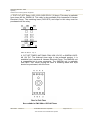


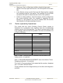


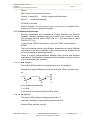
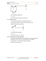
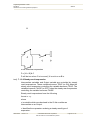


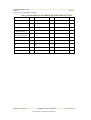
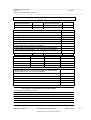
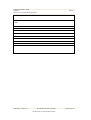


![hank yo_fo buyil_gaSamsung (}a_Te_a ]hs](http://vs1.manualzilla.com/store/data/005691502_1-2e8e29ffb67d0c8f7d0d701e3cb644b7-150x150.png)