1
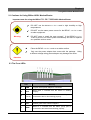
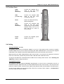
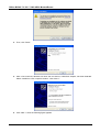
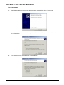
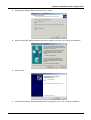
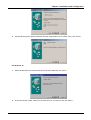
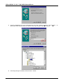
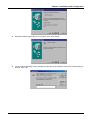
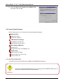
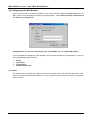
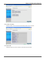
BIPAC-711 C2 / 7100S
ADSL Modem/Router
User’s Manual
Table of Contents
CHAPTER 1 ......................................................................................................................................................... 1
INTRODUCTION...................................................................................................................................................... 1
1.1 An Overview of BIPAC-711 C2 / 7100S ................................................................................................... 1
1.2 Package Contents .................................................................................................................................... 1
1.3 BIPAC-711 C2 / 7100S Features ............................................................................................................. 2
1.4 BIPAC-711 C2 / 7100S Application .......................................................................................................... 3
CHAPTER 2 ......................................................................................................................................................... 4
USING BILLION ADSL MODEM/ROUTER ................................................................................................................. 4
2.1 Cautions for Using Billion ADSL Modem/Router ...................................................................................... 4
2.3 The Front LEDs ........................................................................................................................................ 4
2.3 The Rear Ports ......................................................................................................................................... 5
2.4 Cabling...................................................................................................................................................... 5
CHAPTER 3 ......................................................................................................................................................... 6
CONFIGURATION ................................................................................................................................................... 6
3.1 Before Configuration................................................................................................................................. 6
3.1.1 Installing the USB Driver (711 C2 only)............................................................................................. 6
3.1.2 Configuring the Network Properties................................................................................................. 16
3.2 Factory Default Settings ......................................................................................................................... 20
3.2.1 Username and Password ................................................................................................................ 20
3.2.2 LAN and WAN Port Addresses........................................................................................................ 21
3.3 Information from ISP............................................................................................................................... 21
3.4 Configuring with Web Browser ............................................................................................................... 22
3.4.1 Status............................................................................................................................................... 22
3.4.1.1 Status – ADSL Status ............................................................................................................... 23
3.4.1.1.1 Status – WAN Status ......................................................................................................... 24
3.4.1.1.2 Status – ATM Status .......................................................................................................... 24
3.4.1.2 Status – LAN Status ................................................................................................................. 24
3.4.1.2.1 Status -TCP Status ............................................................................................................ 25
3.4.1.3 Status- PPP .............................................................................................................................. 25
3.4.1.4 Status- Learned MAC Table ..................................................................................................... 26
3.4.1.5 Routing Table ........................................................................................................................... 26
3.4.1.6 System Log ............................................................................................................................... 27
3.4.1.7 Security Logs ............................................................................................................................ 27
3.4.2 Quick Start ....................................................................................................................................... 28
3.4.3 Configuration ................................................................................................................................... 28
3.4.3.1 WAN ......................................................................................................................................... 29
3.4.3.2 LAN ........................................................................................................................................... 31
3.4.3.3 System ...................................................................................................................................... 32
3.4.3.3.1 Password ........................................................................................................................... 32
3.4.3.3.2 Time Zone.......................................................................................................................... 32
3.4.3.3.3 Upgrade ............................................................................................................................. 33
3.4.3.3.4 Factory Setting .................................................................................................................. 33
3.4.3.3.5 Restart ............................................................................................................................... 34
3.4.3.4 Firewall ..................................................................................................................................... 34
3.4.3.4.1 Packet Filter ....................................................................................................................... 35
3.4.3.4.2 Bridge Filtering................................................................................................................... 36
3.4.3.4.3 Intrusion Detection ............................................................................................................. 36
3.4.3.4.4 Block WAN Request .......................................................................................................... 37
3.4.3.4.5 URL Blocking ..................................................................................................................... 38
3.4.3.5 Virtual Server Configuration ..................................................................................................... 38
3.4.3.6 Advanced .................................................................................................................................. 39
3.4.3.6.1 ADSL ................................................................................................................................. 39
3.4.3.6.2 DNS ................................................................................................................................... 40
i
Billion BIPAC-711 C2 / 7100S ADSL Modem/Router
3.4.3.6.3 Dynamic DNS .................................................................................................................... 40
3.4.3.6.4 NAT.................................................................................................................................... 41
3.4.3.6.5 RIP ..................................................................................................................................... 42
3.4.3.6.6 SNMP (7100S only) ........................................................................................................... 43
3.4.3.6.7 Static Routing .................................................................................................................... 43
3.4.3.6.8 MISC Configuration ........................................................................................................... 44
3.4.3.6.9 Diagnostic Test .................................................................................................................. 45
3.4.4 Save Config to Flash ....................................................................................................................... 47
CHAPTER 4 ....................................................................................................................................................... 48
TROUBLESHOOTING ............................................................................................................................................ 48
Problems Starting Up the ADSL Router ....................................................................................................... 48
Problem ............................................................................................................................................ 48
Corrective Action .............................................................................................................................. 48
Problems with the WAN Interface................................................................................................................. 48
Problem ............................................................................................................................................ 48
Corrective Action .............................................................................................................................. 48
Problems with the LAN Interface .................................................................................................................. 48
Problem ............................................................................................................................................ 48
Corrective Action .............................................................................................................................. 48
Problems Connecting to a Remote Node or ISP.......................................................................................... 48
Problem ............................................................................................................................................ 48
Corrective Action .............................................................................................................................. 48
APPENDIX A...................................................................................................................................................... 49
PRODUCT SUPPORT ............................................................................................................................................ 49
ii
Chapter 1
Introduction
1.1 An Overview of BIPAC-711 C2 / 7100S
BIPAC-711 C2 / 7100S ADSL Modem/Router provides a high-speed Ethernet port and an USB (Universal
Serial Bus) port (711 C2) for high-speed Internet browsing. It can support downstream transmission rates
of up to 8Mbps and upstream transmission rates of up to 1024Kbps. It is compliant with Multi-Mode
standard (ANSI T1.413, Issue 2; G.dmt (G.992.1); G.lite (G992.2); G.hs (G994.1)).
The product supports PPPoA (RFC 2364 – PPP (Point-to-Point Protocol) over ATM Adaptation Layer 5),
RFC 1483 encapsulation over ATM (bridged or routed), PPP over Ethernet (RFC 2516), and IPoA
(RFC1577) to establish a connection with ISP. The product also supports VC-based and LLC-based
multiplexing.
It is the perfect solution to connect a small group of PCs to a high-speed broadband Internet connection.
Multi-users can have high-speed Internet access simultaneously.
This product also serves as an Internet firewall, protecting your network from being accessed by outside
users. Not only provide the natural firewall function (Network Address Translation, NAT), it also provides
rich firewall features to secure user’s network. All incoming data packets are monitored and filtered.
Besides, it can also be configured to block internal users from accessing to the Internet.
The product provides two levels of security support. First, it masks LAN users’ IP addresses which are
invisible to outside users on the Internet, making it much more difficult for a hacker to target a machine on
your network. Secondly, it can block and redirect certain ports to limit the services that outside users can
access. For example, to ensure that games and other Internet applications will run properly, user can
open some specific ports for outside users to access internal services in network.
Integrated DHCP (Dynamic Host Control Protocol) services, client and server, allow multiple users to get
their IP addresses automatically on boot up from the product. Simply set local machines as a DHCP
client to accept a dynamically assigned IP address from DHCP server and reboot. Each time local
machine is powered up; the router will recognize it and assign an IP address to instantly connect it to the
LAN.
For advanced users, Virtual Service function allows the product to provide limited visibility to local
machines with specific services for outside users. An ISP (Internet Service Providers) provided IP
address can be set to the product and then specific services can be rerouted to specific computers on the
local network. For instance, a dedicated web server can be connected to the Internet via the product and
then incoming requests for HTML that are received by the product can be rerouted to the dedicated local
web server, even though the server now has a different IP address. In this example, the product is on the
Internet and vulnerable to attacks, but the server is protected.
Virtual Server can also be used to re-task services to multiple servers. For instance, the product can be
set to allow separated FTP, Web, and Multiplayer game servers to share the same Internet-visible IP
address while still protecting the servers and LAN users from hackers.
1.2 Package Contents
1.
Billion BIPAC-711 C2 / 7100S ADSL Modem/Router
2.
One CD-ROM containing the driver and online manual
3.
One Quick Start Guide
4.
One RJ-11 ADSL/telephone cable
1
Billion BIPAC-711 C2 / 7100S ADSL Modem/Router
5.
One CAT-5 straight LAN cable
6.
One USB cable (711 C2)
7.
One power adapter
1.3 BIPAC-711 C2 / 7100S Features
BIPAC-711 C2 / 7100S ADSL Modem/Router provides the following features:
2
z
ADSL Multi-Mode Standard: Supports downstream transmission rates of up to 8Mbps and
upstream transmission rates of up to 1024Kbps. It is compliant with Multi-Mode standard (ANSI
T1.413, Issue 2; G.dmt (G.992.1); G.lite (G992.2); G.hs (G994.1)).
z
Multi-Protocol to Establish A Connection: Supports PPPoA (RFC 2364 - PPP over ATM
Adaptation Layer 5), RFC 1483 encapsulation over ATM (bridged or routed), PPP over Ethernet
(RFC 2516) and IPoA (RFC1577) to establish a connection with ISP. The product also supports VCbased and LLC-based multiplexing.
z
Quick Installation Wizard: Supports a WEB GUI page to install this device quickly. With this wizard,
an end user can enter the information easily which they from the ISP, then surf the Internet
immediately.
z
Universal Plug and Play (UPnP) and UPnP NAT Traversal: This protocol is used to enable
simple and robust connectivity among stand-alone devices and PCs from many different vendors. It
makes network simple and affordable for users. UPnP architecture leverages TCP/IP and the Web
to enable seamless proximity networking in addition to control and data transfer among networked
devices. With this feature enabled, users can now connect to Net meeting or MSN Messenger
seamlessly.
z
Network Address Translation (NAT): Allows multi-users to access outside resource such as
Internet simultaneously with one IP address/one Internet access account. Besides, many application
layer gateway (ALG) are supported such as web browser, ICQ, FTP, Telnet, E-mail, News, Ping and
others.
z
Domain Name System (DNS) relay: Provides an easy way to map the domain name (a friendly
name for user such as www.yahoo.com) and IP address. When local machine sets its DNS server
with this router’s IP address. Then every DNS conversion request packet from the PC to this router
will be forwarded to the real DNS in outside network. After the router gets the reply, then forwards it
back to the PC.
z
Dynamic Domain Name System (DDNS): The Dynamic DNS service allows you to alias a dynamic
IP address to a static hostname. This dynamic IP address is the WAN IP address. For example, to
use the service, you must first apply an account from this free Web server http://www.dyndns.org/.
There are more than 5 DDNS servers supported.
z
PPP over Ethernet (PPPoE): Provides embedded PPPoE client function to establish a connection.
Users can get greater access speed without changing the operation concept, sharing the same ISP
account and paying for one access account. No PPPoE client software is required for local
computer. The Automatic Reconnect and Disconnect Timeout (Idle Timer) functions are provided,
too.
z
Virtual Server: User can specify some services to be visible from outside users. The router can
detect incoming service request and forward it to the specific local computer to handle it. For
example, user can assign a PC in LAN acting as WEB server inside and expose it to the outside
network. Outside user can browse inside web server directly while it is protected by NAT. A DMZ
host setting is also provided to a local computer exposed to the outside network, Internet.
z
Firewall: Supports SOHO firewall with NAT technology. Automatically detects and blocks the Denial
of Service (DoS) attack. The URL-blocking and packet filtering are also supported. The hacker’s
Chapter 1 Introduction
attack will be recorded associated with timestamp in the security logging area. More firewall features
will be added continually, please visit our web site to download latest firmware.
z
Dynamic Host Control Protocol (DHCP) client and server: In the WAN site, the DHCP client can
get an IP address from the Internet Server Provider (ISP) automatically. In the LAN site, the DHCP
server can allocate multiple clients IP addresses and distribute them including IP address, subnet
mask as well as DNS IP address to local computers. It provides an easy way to manage the local IP
network.
z
Rich Packet Filtering: Not only filter the packet based on IP address, but also based on Port
numbers and MAC address. It will increase the performance in LAN and WAN, also provide a
higher-level security control
z
SNTP: An easy way to get the network real time information from an SNTP server.
z
Web based GUI: Supports web based GUI for configuration and management. It is user-friendly
and comes with on-line help. It also supports remote management capability for remote users to
configure and manage this product.
1.4 BIPAC-711 C2 / 7100S Application
711 C2
7100S
3
Chapter 2
Using Billion ADSL Modem/Router
2.1 Cautions for Using Billion ADSL Modem/Router
Important note for using the BIPAC-711 C2 / 7100S ADSL Modem/Router
Warning
9
DO NOT use the BIPAC-711 C2 / 7100S in high humidity or high
temperatures.
9
DO NOT use the same power source for the BIPAC- 711 C2 / 7100S
as other equipment.
9
DO NOT open or repair the case yourself. If the BIPAC-711 C2 /
7100S is too hot, turn off the power immediately and have it repaired
at a qualified service center.
Place the BIPAC-711 C2 / 7100S on a stable surface.
9
9
Only use the power adapter that comes with the package. Using
a different voltage rating power adaptor may damage the router.
Attention
2.3 The Front LEDs
LED
1
PWR
Lit green when power adapter is connected.
2
SYS
When flash, it indicates that the device is working
properly.
(711 C2)
When this LED is lit, it indicates that the USB port is
connected to the PC and working properly.
4
LNK
Lit green when the LAN link is connected.
5
COL
Flashes green when collision happens
7
ADSL
When lit, it indicates that the ADSL (Line) port is
connected to the DSLAM and working properly.
3
4
Meaning
USB
Chapter 2 Using the ADSL Modem/Router
2.3 The Rear Ports
LINE
(RJ-11
connector)
Connect the supplied RJ-11
cable to this port when
connecting to the ADSL
USB
(711 C2 only)
Connect the supplied USB
cable to this port when
connecting to the PC.
Reset
Press it to restore the factory
default setting back
LAN
(RJ-45
connector)
Connect the supplied LAN
cable to this port when
connecting to a NIC (Network
Interface card) in PC or to a
LAN such as an office or
home network.
Power
(jack)
Connect the supplied power
adapter to this jack.
2.4 Cabling
Through USB Port (711 C2)
The product can be used as a Network Adapter on your PC. That means you do not have to install a
network adapter first on your PC before connecting the ADSL Modem/Router. Just connect the supplied
USB cable to the USB port of the ADSL Modem/Router and connect the other end to the PC.
Make sure that your ADSL Modem/Router and PC are turned on. On the front of the product is a bank of
LEDs. As a first check, please verify that the PWR, USB and ADSL SYN LEDs are lit.
As long as the cables are connected and the LEDs are lit normally, follow section “3.1.1 Installing the
USB Driver” below to setup this device.
Through Ethernet Port
The product’s LAN port supports MDI/MDIX auto-detection, so that it can be connected to the PC or
HUB/Switch directly. Make sure that your ADSL Modem/Router and PC are turned on. On the front of the
product is a bank of LEDs. As a first check, please verify that the PWR, LNK and ADSL SYN LEDs are lit.
As long as the cables are connected and the LEDs are lit normally, follow chapter 3 “Configuration”
below to modify the network settings.
5
Chapter 3
Configuration
3.1 Before Configuration
The router can be configured with your web browser. A web browser is included as a standard application
in the following operating systems: Linux, Mac OS, Windows 98/NT/2000/XP/Me, etc. The product provides
a very easy and user-friendly interface for configuration.
PCs must have an Ethernet interface installed properly and be connected to the router either directly or
through an external repeater hub, and have TCP/IP installed and configured to obtain an IP address
through a DHCP server or a fixed IP address that must be in the same subnet as the router. The default IP
address of the router is 192.168.1.254 and the subnet mask is 255.255.255.0 (i.e. any attached PC must
be in the same subnet, and have an IP address in the range of 192.168.1.1 to 192.168.1.253). The best
and easiest way is to configure the PC to get an IP address automatically from the router using DHCP. If
you encounter any problems accessing the router’s web interface it may also be advisable to uninstall any
kind of software firewall on your PCs, as they can cause problems accessing the 192.168.1.254 IP address
of the router. Users should make their own decisions on how to best protect their network.
Please follow the steps below for your PC’s network environment installation. First of all, please check your
PC’s network components. The TCP/IP protocol stack and Ethernet network adapter must be installed. If
not, please refer to your Windows-related or other operating system manuals.
Any TCP/IP capable workstation can be used to communicate with or through
the BIPAC-711 C2 / 7100S. To configure other types of workstations, please
consult the manufacturer’s documentation.
3.1.1 Installing the USB Driver (711 C2 only)
If you connect the ADSL Modem/Router through USB port, for the first time the USB cable is connected to
the PC, Windows will automatically detect the device. Follow the steps to install the USB driver.
For Windows XP
1. When Windows tells you that the new device has been detected, select “Install from a list or specific
location” and click “Next >”.
6
Chapter 3 Installation and Configuration
2. Insert the installation CD into the CD-ROM drive. Check “Search removable media” and click “Next >”.
Then, it takes seconds to search and install the software.
3. When windows titled “Hardware Installation” or “Software Installation” appears, press “Continue
Anyway” to go on.
7
Billion BIPAC-711 C2 / 7100S ADSL Modem/Router
4. Then, click “Finish”.
5. After a few moments, Windows will show the new device, USB ADSL Adapter, has been detected.
Select “Install from a list or specific location”. Click “Next >”.
6. Click “Next >” when the following figure appears.
8
Chapter 3 Installation and Configuration
7. When windows titled “Hardware Installation” appears, press “Continue Anyway”.
8. Then, click “Finish” to end the installation.
9. After installing the driver, follow the section “3.2 Configuring the Network Properties” below to
modify the network settings on your PC.
9
Billion BIPAC-711 C2 / 7100S ADSL Modem/Router
For Windows 2000
1. When Windows tells you that the new device has been detected, click “Next >” to continue.
2. Select “Search for a suitable driver for my device”. Click “Next>”. Then, insert the installation CD into
the CD-ROM drive.
3. In next window, check “CD-ROM drives” and click “Next>”.
10
Chapter 3 Installation and Configuration
4. Continuing through the Wizard, click the “Next >” button.
5. When window titled “Digital Signature Not Found” appears, press “Yes” to continue the installation.
6. Press “Finish”.
7. If the following window “Digital Signature Not Found” appears, press “Yes” to end the installation.
11
Billion BIPAC-711 C2 / 7100S ADSL Modem/Router
For Windows Me
1. When Windows tells you that the new device has been detected. Select “Specify the location of the
driver” and click “Next >”.
2. Insert the installation CD into the CD-ROM drive and check “Removable Media”. Click “Next>” to
continue.
3. Continuing through the Wizard, click the “Next >” button.
12
Chapter 3 Installation and Configuration
4. Continuing through the Wizard, Windows will start copying files to your system. Then, click “Finish”.
For Windows 98
1. When Windows tells you that the new device has been detected, click “Next >”.
2. In the next window, select “Search for the best driver for your device” and click “Next >”.
13
Billion BIPAC-711 C2 / 7100S ADSL Modem/Router
3. Insert the installation CD into the CD-ROM drive and check “Specify a location”. Click “Browse…” to
specify the driver directory such as F:\Driver\. Click “OK” and then “Next>” to continue.
4. Continuing through the Wizard, click the “Next >” button.
14
Chapter 3 Installation and Configuration
5. Windows will start copying files to your system. Then, click “Finish”.
6. You will see the following screen prompting for the path of the Windows source files. Please specify a
location. Click “OK”.
15
Billion BIPAC-711 C2 / 7100S ADSL Modem/Router
3.1.2 Configuring the Network Properties
Configuring PC in Windows XP
1. Go to Start / Control Panel (in Classic View). In the
Control Panel, double-click on Network Connections.
2. Double-click Local Area Connection.
3. In the Local Area Connection Status window, click
Properties.
16
Chapter 3 Installation and Configuration
4. Select Internet Protocol (TCP/IP) and click Properties
5. Select the Obtain an IP address automatically and the
Obtain DNS server address automatically radio
buttons.
6. Click OK to finish the configuration.
Configuring PC in Windows 2000
1.
Go to Start / Settings / Control Panel. In the Control
Panel, double-click on Network and Dial-up
Connections.
2.
Double-click Local Area Connection.
3.
In the Local Area Connection Status window, click
Properties.
17
Billion BIPAC-711 C2 / 7100S ADSL Modem/Router
4.
Select Internet Protocol (TCP/IP) and click
Properties.
5.
Select the Obtain an IP address automatically and
the Obtain DNS server address automatically radio
buttons
6.
Click OK to finish the configuration.
Configuring PC in Windows 98/ME
1. Go to Start / Settings / Control Panel. In the
Control Panel, double-click on Network and choose the
Configuration tab.
2. Select TCP / IP -> NE2000 Compatible, or the name
of your Network Interface Card (NIC) in your PC.
3. Click Properties.
18
Chapter 3 Installation and Configuration
4. Select the IP Address tab. In this page, click the
Obtain an IP address automatically radio button.
5. Then select the DNS Configuration tab.
6. Select the Disable DNS radio button and click OK to
finish the configuration.
Configuring PC in Windows NT4.0
1.
Go to Start / Settings / Control Panel. In the Control
Panel, double-click on Network and choose the
Protocols tab.
2.
Select TCP/IP Protocol and click Properties.
19
Billion BIPAC-711 C2 / 7100S ADSL Modem/Router
3.
Select the Obtain an IP address from a DHCP server
radio button and click OK.
3.2 Factory Default Settings
Before configuring your, you need to know the following default settings.
Web Interface:
Username: admin
Password: Password
LAN Device IP Settings:
IP Address: 192.168.1.254
Subnet Mask: 255.255.255.0
ISP setting in WAN site:
VPI/VCI: 0/32
Encapsulation: RFC-1483 Bridged, LLC
DHCP server:
DHCP server is enabled.
Start IP Address: 192.168.1.100
IP pool counts: 100
3.2.1 Username and Password
The default username and password are “admin” and “Password” respectively.
If you ever forget the password to log in, you may press the RESET button up to 6
seconds to restore the factory default settings.
Attention
Attenti
20
Chapter 3 Installation and Configuration
3.2.2 LAN and WAN Port Addresses
The parameters of LAN and WAN ports are pre-set in the factory. The default values are shown below.
LAN Port
IP address
192.168.1.254
Subnet Mask
255.255.255.0
DHCP server function
Enabled
IP addresses for
distribution to PCs
100 IP addresses continuing from
192.168.1.100 through
192.168.1.199
WAN Port
Encapsulation: RFC-1483
Bridged, LLC
3.3 Information from ISP
Before configuring this device, you have to check with your ISP (Internet Service Provider) what kind of
service is provided such as PPPoE, PPPoA, RFC1483, IPoA, or PPTP-to-PPPoA Relaying.
Gather the information as illustrated in the following table and keep it for reference.
PPPoE
VPI/VCI, VC-based/LLC-based multiplexing, Username, Password, Service
Name, and Domain Name System (DNS) IP address (it can be
automatically assigned by your ISP when you connect or be set manually).
PPPoA
VPI/VCI, VC-based/LLC-based multiplexing, Username, Password, and
Domain Name System (DNS) IP address (it can be automatically assigned
by your ISP when you connect or be set manually).
RFC1483 Bridged
RFC1483 Routed
VPI/VCI, VC-based/LLC-based multiplexing to use Bridged Mode.
VPI/VCI, VC-based/LLC-based multiplexing, IP address, Subnet mask,
Gateway address, and Domain Name System (DNS) IP address (it is fixed
IP address).
IPoA
VPI/VCI, VC-based/LLC-based multiplexing, IP address, Subnet mask,
Gateway address, and Domain Name System (DNS) IP address (it is fixed
IP address).
21
Billion BIPAC-711 C2 / 7100S ADSL Modem/Router
3.4 Configuring with Web Browser
Open your web browser, enter the IP address of your router, which by default is 192.168.1.254, and click
“Go”, a user name and password window prompt will appear. The default username and password
are “admin” and “Password”.
Congratulation! You are now successfully logon to the BIPAC-711 C2 / 7100S ADSL Router!
At the configuration homepage, the left navigation pane where bookmarks are provided links you directly
to the desired setup page, including:
¾
¾
¾
¾
Status
Quick Start
Configuration
Save Config to Flash
3.4.1 Status
The Status section provides and contains many items including device H/W and S/W information, LAN,
WAN, Port status and all defined interfaces. It also provides useful information for users to review the
status of device
22
Chapter 3 Installation and Configuration
3.4.1.1 Status – ADSL Status
Displays the status of your ADSL connection. It will refresh every two seconds
23
Billion BIPAC-711 C2 / 7100S ADSL Modem/Router
3.4.1.1.1 Status – WAN Status
3.4.1.1.2 Status – ATM Status
3.4.1.2 Status – LAN Status
Displays the status of your Local Area Network (LAN) connection.
24
Chapter 3 Installation and Configuration
3.4.1.2.1 Status -TCP Status
Display the status of TCP. This screen will automatically refresh every two seconds.
3.4.1.3 Status- PPP
Displays the status of your PPP connection. It will refresh every ten seconds.
25
Billion BIPAC-711 C2 / 7100S ADSL Modem/Router
3.4.1.4 Status- Learned MAC Table
Aging Timeout: Enter the time period for the router to memorize MAC addresses.
3.4.1.5 Routing Table
Display the current routing paths of BIPAC-711 C2 / 7100S.
26
Chapter 3 Installation and Configuration
3.4.1.6 System Log
Display the system logs cumulated till the present time. You can trace the historical information through
this function.
3.4.1.7 Security Logs
Display the information of security logs. If hacker attacks your sever, he will be isolated by the firewall
function and the router will record related information. Hence, you know where the hacker comes from.
27
Billion BIPAC-711 C2 / 7100S ADSL Modem/Router
3.4.2 Quick Start
If you use this device to access the Internet through the ISP, this web page is enough for you to configure
this router and access the Internet without a problem. Please check Chapter 3.3 (Information from the
ISP), then enter the proper values into this web page, click the Apply button and then click the Save
Config button to save all of the configuration parameters to FLASH. After the router reboot, you may
check the Status web page to check whether the router is connected to the ISP or not. In most cases, you
can access the Internet immediately. If not, please refer to the sections below for more information.
3.4.3 Configuration
When you click this item, you get following sub-items to configure BIPAC-711 C2 / 7100S.
WAN, LAN, System, Firewall, Virtual Server, and Advanced.
28
Chapter 3 Installation and Configuration
3.4.3.1 WAN
Pvc0 is set as default and then press submit.
The screens below contain settings for the WAN interface toward Internet.
Per VC Settings
There are eight Virtual Circuits (VC) for you to set, from VC 0 to VC 7. Before you make the settings,
please scroll down to the button of the page and select the item of Virtual Circuit you want to configure.
Enabled? : Select Yes if you want to enable the settings of this VC or select No if you want to disable the
settings of this VC.
VPI: Consult the telephone company to get the Virtual Path Identifier (VPI) number. The default value is 0.
VCI: Consult the telephone company to get the Virtual Channel Identifier (VCI) number. The default value
is 32.
Static IP Address: Enter the information provided by your ISP.
29
Billion BIPAC-711 C2 / 7100S ADSL Modem/Router
Subnet Mask: Enter the information provided by your ISP.
Default Gateway: Enter the gateway address provided by your ISP.
MAC SPOOFING : The MAC Spoofing is for solving the scenario when the ISP only recognizing the
specified MAC address.
Service Category: Select UBR or CBR.
Bandwidth: Enter the bandwidth.
ENCAPSULATION: There are eleven ways ─ PPPoE VC-Mux, PPPoE LLC, PPPoE None, PPPoA VCMux, PPPoA LLC, 1483 Bridged IP VC-Mux, 1483 Bridged IP LLC, 1483 Routed IP VC-Mux, 1483
Routed IP LLC, Classical IP over ATM, Native ATM ─ for the device to have a public IP address and then
to access Internet. You have to check with your ISP about which way is adopted.
BRIDGE: If you set this device to be bridge mode, select Enable; if not, please select Disable.
IGMP: You can Enable or Disable this function.
PPP: If your encapsulation is set to be PPPoE or PPPoA, the following fields must be entered.
Service Name: This item is for identification purpose. If it is required, your ISP will provide you the
information. Maximum input is 31 alphanumeric characters.
Username: Enter the username provided by your ISP.
Password: Enter the password provided by your ISP.
Disconnect Timeout seconds: Auto-disconnect the ADSL Router when there is no activity on the
line for a predetermined period of time. You can input any number from 0 to 32767. The default value is 0
seconds.
MRU: Maximum Receive Unit indicates the peer of PPP connection the maximum size of the PPP
information field this device can be received. The default value is 1492 and is used in the beginning of the
PPP negotiation. In the normal negotiation, the peer will accept this MRU and will not send packet with
information field larger than this value.
30
Chapter 3 Installation and Configuration
MTU: Maximum Transmission Unit indicates the network stack of any packet is larger than this value will
be fragmented before the transmission. During the PPP negotiation, the peer of the PPP connection will
indicate its MRU and will be accepted. The actual MTU of the PPP connection will be set to the smaller
one of MTU and the peer’s MRU. The default value is 1492.
MSS: Maximum Segment Size is the largest size of data that TCP will send in a single IP packet. When a
connection is established between LAN client and a host in the WAN side, the LAN client and the WAN
host will indicate their MSS during the TCP connection handshake. The default value is 1492.
Authentication: Default at “Auto”.
Automatic Reconnect: Check to enable this device to automatically re-establish the PPPoE session
when disconnected by ISP.
DHCP client enable: Check to enable the DHCP client function if you want the device to get an IP
address automatically from your ISP.
Host Name: Enter the name of your work group.
3.4.3.2 LAN
This screen contains settings for LAN interface attached to the LAN port.
IP Address: Default at 192.168.1.254.
This is the device IP address in LAN site. If you plan to change it to another IP address to a different
range of IP subnet. Please make sure your PC is also located at the same IP subnet. Otherwise, you may
not be able to access the router.
Subnet Mask: Default at 255.255.255.0.
DHCP Server: Check DHCP Server to enable the router to distribute IP Addresses, subnet mask and
DNS setting to computers. Hence, the following fields will be activated. If you do not check this selection,
remember to specify a static IP address, subnet Mask, and DNS setting for each of your local computers.
Be careful not to assign the same IP address to different computers.
Address pool selection: Auto or User Defined. If select the AUTO, router will assign an IP address back
to PC’s IP request. If User Defined, please specify the IP pool range.
31
Billion BIPAC-711 C2 / 7100S ADSL Modem/Router
Start Address: Enter the start address of this local IP network address pool. The pool is a piece of
continuous IP address segment. The default value is 192.168.1.100.
End Address: Enter the last address of this local IP network address pool that you want the DHCP
server to assign IP addresses to. The default value is 192.168.1.199.
With this case, the DHCP pool is from 192.168.1.100 to 192.168.1.199. Therefore, the local computer will
get an IP address located at this range randomly.
3.4.3.3 System
There are six items under the System section: Password, Time Zone, Upgrade, Factory Setting, and
Reboot.
3.4.3.3.1 Password
In factory setting, there is no password protection when user accesses BIPAC-711 C2 / 7100S. It is
recommended that you change the default password <BLANK> to ensure that someone cannot adjust
your settings without your permission. <BLANK> means there is no password. Every time you change
your password, please record the password and keep it at a safe place.
Please note that the maximum input for password is 16 alphanumeric characters long. Since it is case
sensitive, be sure that you remember whether a letter is in upper or lower case and make sure that your
Caps Lock is off.
3.4.3.3.2 Time Zone
BIPAC-711 C2 / 7100S does not have a real time clock on board; instead, it uses the simple network time
protocol (SNTP) to get the current time from the SNTP server in outside network. Please choose your
local time zone and click Submit. You will get the correct time information after you really establish a
connection to Internet. The current time of selected time zone will be shown in the Status – System
window.
Automatically adjust clock for daylight saving changes: It is optional for different time zone area.
SNTP Server IP Address: Specify the IP address if you want to use your familiar SNTP server.
32
Chapter 3 Installation and Configuration
3.4.3.3.3 Upgrade
To upgrade the firmware of BIPAC-711 C2 / 7100S, you should download or copy the firmware to your
local environment first. Press the “Browse…” button to specify the path of the firmware file. Then, click
“Upgrade” to start upgrading. When the procedure is completed, BIPAC-711 C2 / 7100S will reset
automatically to make the new firmware work.
3.4.3.3.4 Factory Setting
If for any reason, you have to reset this router back to factory default settings, be careful that the current
settings will be lost and the settings are reset back to its default value. The factory default values is
detailed in the section 3.2 ‘‘Factory Default Settings’’.
33
Billion BIPAC-711 C2 / 7100S ADSL Modem/Router
3.4.3.3.5 Restart
In case the router stops responding correctly or in some other way stops functioning, you can perform the
reboot. Your setting won’t be changed. Performing the reboot, click on the Restart button.
3.4.3.4 Firewall
User can decide to enable this firewall function including Packet Filter, Block Hacker Attack, and Block
WAN request features for better security control or not. But be noted, it wastes network processor
computation power. The performance will be lower about 10% to 15%. More firewall features will be
added continually, please visit our web site to download latest firmware.
34
Chapter 3 Installation and Configuration
3.4.3.4.1 Packet Filter
Packet filtering function enables you to configure your router to check specified internal/external user (IP
address) from Internet access, or you can disable specific service request (Port number) to /from
Internet. This configuration program allows you to set up different filter rules up to 10 for different users
based on their IP addresses or their network Port number. The relationship among all filters is “or”
operation, which means the device checks these different filter rules one by one, stating from the first rule.
As long as one of the rules is satisfied, the specified action will be taken.
Add: Click this button to add a new packet filter rule. After click, next figure will appear.
Edit: Check the Rule No. you want to edit. Then, click the “Edit” button.
Delete: Check the Rule No. you want to delete. Then, click the “Delete” button.
~ Outgoing
~ Incoming: Determine whether the rule is for outgoing packets or for incoming packets.
Active: Choose “Yes” to enable the rule, or choose “No” to disable the rule.
Packet Type: Specify the packet type (TCP, UDP, ICMP or any) that the rule will be applied to.
Select TCP if you want to scope for the connection-based application service on the remote server using
the port number. Or select UDP if you want to scope for the connectionless application service on the
remote server using the port number.
Log: Choose “Yes” if you want to generate logs when the filer rule is applied to a packet.
Action When Matched: If any packet matches this filter rule, Forward or Drop this packet.
Source IP Address: Enter the incoming or outgoing packet’s source IP address(es).
Source Port: Check the TCP or UDP packet’s source port number(s).
Destination IP Address: Enter the incoming or outgoing packet’s destination IP address(es).
Destination Port: Check the TCP or UDP packet’s destination port number(s).
35
Billion BIPAC-711 C2 / 7100S ADSL Modem/Router
If the DHCP server option is enabled, you have to be very careful in assigning the IP
addresses of filtered private IP range in order to avoid conflicts because you do not know
which PC in LAN is assigned to which IP address. The easiest and safest way is that the
filtered IP address is assigned to specific PC that is not allowed to access outside resource
such as Internet. You configure the filtered IP address manually to this PC, but it is still in the
same subnet with the router.
3.4.3.4.2 Bridge Filtering
Enable Bridge Filtering: Check Yes to enable this function or check No to disable.
Source MAC: Enter the source MAC address.
Destination MAC: Enter the destination MAC address.
Type: Enter the Ethernet type.
~ Block ~ Forward: Check Block if you want to block requests from the source MAC address sending
to the destination MAC address. Check Forward if you want to forward requests from the source MAC
address sending to the destination MAC address.
3.4.3.4.3 Intrusion Detection
Check “Enable” if you want to detect invader sneak in your computer without permitted .The ADSL Router
can automatically detect and block the DoS (Denial of Service) attack if user enables this function. This
kind of attack is not to achieve the confidential data of this network; instead, it aims to crush specific
equipment or the entire network. If this happens, the users will not be able to access the network
resources. There are few samples of hacker patterns implemented as below.
-
IP Spoofing
-
Ping of Death (Length > 65535)
-
Land Attack (Same source / destination IP address)
-
IP with zero length
-
Sync flooding
36
Chapter 3 Installation and Configuration
-
Smurf Attack (ICMP Echo with x.x.x.0 or x.x.x.255)
-
Snork Attack
-
UDP port loop-back
-
TCP NULL scan
3.4.3.4.4 Block WAN Request
Check “Enable” if you want to exclude outside PING request from reaching on this router.
37
Billion BIPAC-711 C2 / 7100S ADSL Modem/Router
3.4.3.4.5 URL Blocking
URL blocking function enables you to avoid your LAN PCs from accessing some URLs. You must check
the “Enable” radio button to make the following figure appear for further configuration.
Always Blcok: Check this will block all browsing requests from PCs
Block: to specify the the time period when you want this function activated. But be noted that SNTP
(Time Zone) function must WORK.
Keyword Filtering: Check if you want to enable the Keyword Filtering function and click the hyper link to
enter further configuration.
Use Domain Filtering: Check if you wan to enable the Domain Filtering function and click the hyper link
to enter further information.
3.4.3.5 Virtual Server Configuration
Being a natural Internet firewall, the ADSL Router protects your network from being accessed by outside
users. When it needs to allow outside users to access internal servers, e.g. Web server, FTP server, Email server or News server, this product can act as a virtual server. You can set up a local server with
specific port number that stands for the service, e.g. Web (80), FTP (21), Telnet (23), SMTP (25), POP3
(110), DNS (53), ECHO (7), NNTP (119). When an incoming access request to the router for specified
port is received, it will be forwarded to the corresponding internal server.
38
Chapter 3 Installation and Configuration
For example, if you set the Public Port number 21 (FTP) to be mapped to the IP Address 192.168.1.100,
then all the ftp requests from outside users will be forwarded to the local server with IP address of
192.168.1.100.
Port (from) & Port (To): Enter the public port number & range you want to configure.
Port Type: Select TCP if you want to scope for the connection-based application service on the remote
server using the port number. Or select UDP if you want to scope for the connectionless application
service on the remote server using the port number.
Host IP Address: Enter the IP address of certain internal server to which requests from the specified port
is forwarded.
3.4.3.6 Advanced
There are eight items under the Advanced section: ADSL,DNS. Dynamic DNS, NAT. RIP. Static Routing,
MISC Configuration, Diagnostic Test .
3.4.3.6.1 ADSL
Trellis: Default at Enabled.
Handshake Protocol: Default at Autosense – G.dmt first. You can also choose other protocols, such
as Autosense – T1.413 first, G.dmt/G.lite, T1.413, G.dmt, G.lite.
Wiring Selection: Default at Tip/Ring. Select Auto or A/A1 if necessary.
39
Billion BIPAC-711 C2 / 7100S ADSL Modem/Router
3.4.3.6.2 DNS
A Domain Name System (DNS) contains a mapping table for domain name and IP address. In the
Internet, every host has a unique and friendly name such as www.yahoo.com and IP address. The IP
address is so hard to remember that you may just enter the friendly name www.yahoo.com and then the
DNS will convert it to its equivalent IP address.
You can obtain Domain Name System (DNS) IP address automatically if ISP provides it when you logon.
Or your ISP may provide you with an IP address of DNS. If this is the case, you must enter the DNS IP
address.
3.4.3.6.3 Dynamic DNS
With Dynamic DNS service, a domain name can be translated into a dynamic IP address, which is often
issued by ISP for dial-up service. A local server, such as Web server, Email server or FTP server, can
then be easily accessed without knowing the changing IP address.
Check the “Enable” button to access the Dynamic DNS service. You may sign up Dynamic DNS service
at http://www.dyndns.org and there you can also register domain names.
Host: Enter one domain name you have registered.
User Name: Enter the username used for sign-up.
Password: Enter the password used for sign-up.
Period: Set the time period for the Router to exchange information with the DDNS server. In addition to
update periodically according to this period setting, BIPAC-711 C2 / 7100S will take the same action
automatically whenever the assigned IP changes
40
Chapter 3 Installation and Configuration
3.4.3.6.4 NAT
The NAT Configuration page allows the user to set the configuration for the Network Address
Translation.
Dynamic NAPT: It provides dynamic Network Address Translation capability between LAN and multiple
WAN connections, and the LAN traffic is routed to appropriate WAN connections based-on the
destination IP addresses and Rout Table. This eliminates the need for the static NAT session
configuration between multiple LAN clients and multiple WAN connections.
NAT (Static): This option maps single WAN IP address to the local PC IP address. It is peer-to-peer
mapping, one-to-one. For each WAN interface, only one local PC IP address can be associated with each
WAN interface. Click the link Session Name Configuration to add the session name for WAN interface.
NAPT (Static): This option maps the single WAN IP address to many local PCs IP addresses, one-tomany. It is the multiple-mapping mechanism. For each WAN interface, more than one local PC can be
associated with one WAN interface. Click the Session Name Configuration to add the session name for
WAN interface.
Session Name: Enter the desired session name.
User’s IP: Allows the user to assign the IP address to map the corresponding NAT/NAPT sessions.
Session Name status will be displayed at the middle of this page to show the corresponding Session
Name with its IP address.
Click Session Name Configuration, the following screen displays.
Session Name: Enter the desired session name.
41
Billion BIPAC-711 C2 / 7100S ADSL Modem/Router
Interface: This field allows the user to choose specific WAN interface (PVC or PPP Session) for NAT
session.
NAT allows only one entry (User IP) per session, NAPT allows many entries (User IPs) per session.
Select Add or Delete and then press the Submit button to add or delete any NAT session name setting
to/from the following table.
Go back to the previous page, NAT Configuration, to continue further settings.
3.4.3.6.5 RIP
RIP: Default at Disabled.
Supplier: Default at True.
Gateway: Default at False.
Multicast: Default at False.
Interval seconds: The default value is 30 seconds.
42
Chapter 3 Installation and Configuration
3.4.3.6.6 SNMP (7100S only)
Simple Network Management Protocol (SNMP) is an optional feature that may or may not be supported
by your ADSL Bridge/Router.
SNMP is an application layer protocol that is used for managing networks. SNMP is an optional feature
that may or may not be in the specific firmware that you are working with. There are several components
that make up the SNMP structure, including agents, network management stations (NMS), network
management protocols, and a management information base (MIB). An SNMP agent is a node that
resides on the network, typically a computer or a router. The SNMP agent is controlled and configured by
the NMS by sending SNMP messages between one another. SNMP agents are logged and identified in a
Management Information Base (MIB), in which they are identified by an object identifiers (OID).
One feature of SNMP is SNMP traps. SNMP traps are used to notify network managers of significant
events that have taken place in the network. These traps are sent to the SNMP NMS (NMS Server
located at Trap IP) through the specified ports.
SNMP System Identification: The System Name, System Contact, System Location, and System OID
are provided to identify the SNMP NMS. The System OID is the ID number placed in all Trap reports.
The System Name, System Contact, and System Location can be up to 127characters. Default value for
System OID is 1.3.6.1.4.1.4900. Read Community: This is the password to access public information.
The Read Community can be up to 127 characters. Default is “public.” Write Community: This is the
password to access private information.
The Write Community can be up to 127 characters. Default is “private.” Trap Community: This is the
password to access and view SNMP traps.
The Trap Community can be up to 127 characters. Default is “trap community.” Trap SNMP Version:
Select from Version 1 or Version 2. Default is Version 1. Trap IP: This is the IP address to which SNMP
traps are sent. There can be up to 5 different SNMP trap destination IP addresses. Trap Port: This is the
corresponding port for the SNMP trap (see Trap IP above)
3.4.3.6.7 Static Routing
If you have another router with a LAN-to-LAN connection, you may create a static routing on the router
that is the gateway to Internet.
43
Billion BIPAC-711 C2 / 7100S ADSL Modem/Router
Add: Click this button to add a new static routing. When you click this button, the next figure appears.
Edit: Check the item you want to edit. Then, click the “Edit” button.
Delete: Check the item you want to delete. Then, click the “Delete” button.
Destination Subnet / Dest. Subnet Mask / Gateway Address: Fill in these fields required by this Static
Routing function.
3.4.3.6.8 MISC Configuration
WAN side HTTP server: Default at Disabled. Or you may check it and specify the IP address or a group
of IPs (subnet) allowed to access router.
HTTP server port: Default at 80
FTP/TFTP server: Router can act as a FTP server
44
Chapter 3 Installation and Configuration
DMZ, DMZ Host IP: Enable this and specify the DMZ Host IP to access any incoming request packets
from WAN site.
DHCP realy/DHCP Target IP: Enable this and specify the DHCP server IP address for DHCP relay
function.
ICMP Proxy: Enable/Disable the IGMP proxy function.
PPP Auto Reconnection: To enable this function to re-establish the PPP connection again after there
was a timeout causing PPP connection is terminated.
PPP Half Bridge: Enable this, router will get an IP address from ISP and passing it to behind PC. At this
time, the router works as a BRIDGE but using PPP to login.
UPnP : Universal Plug and Play (UPnP) is an architecture for pervasive peer-to-peer network connectivity
of PCs and intelligent devices or appliances, particularly within the home. UPnP builds on Internet
standards and technologies, such as TCP/IP, HTTP, and XML, to enable these devices to automatically
connect with one another and work together to make networking - particularly home networking - possible
for more people.
The UPnP aware applications such as MSN Messenger will discover that they are behind a NAT router,
learn the external IP address and configure port mappings on the router to forward packets from the
external ports of the router to the internal ports used by the application.
3.4.3.6.9 Diagnostic Test
As soon as you enter the test program, all tests will run automatically to diagnose the connection status of
the device.
Checking LAN Connection
Testing Ethernet LAN connection
This test passes if the Ethernet LAN interface is working properly.
Checking ADSL Connection
Testing ADSL Synchronization
This test checks your DSL modem to see if it can successfully negotiate and establish a DSL
connection with your service provider's central office equipments. The test returns PASS if a DSL
connection is established.
45
Billion BIPAC-711 C2 / 7100S ADSL Modem/Router
If this test returns FAIL, please try the test again a few minutes after this test is completed. Since your
DSL modem need a couple of seconds to a few minutes to establish the DSL connection depending
on your phone line quality. If this test returns FAIL, make sure your phone line is connected to your
DSL modem securely, and also check with your service provider to see if your service is activated.
If this test returns FAIL, all other tests will be skipped.
Checking Circuit 0 for Network Connection
Test ATM OAM Segment Loop Back
This test sends ATM OAM F5 Segment loop back request cells to the central office equipments
through your DSL connection. This test will pass if response cell is received. Since your service
provider might not support this test, your DSL modem could still work even if this test fails.
If this test fails consistently and your DSL modem seems not working, check to make sure the VPI and
VCI are configured correctly.
This test returns FAIL if the DSL synchronization test failed.
Test ATM OAM End-to-End Loop Back
This test sends ATM OAM F5 End-to-End loop back request cells to the central office equipments
through your DSL connection. This test returns PASS if response cell is received. Since your service
provider might not support this test, your DSL modem could still work even if this test fails.
If this test return FAIL consistently and your DSL modem seems not working, check to make sure the
VPI and VCI are configured correctly.
This test returns SKIPPED if the DSL synchronization test failed.
Test Ethernet connect to ATM
This test returns PASS if the ATM AAL5 module is loaded correctly in your DSL modem. If this test
returns FAIL, an internal error has occurred.
This test returns SKIPPED if the DSL synchronization does not return PASS.
Test PPPoE connection
This test returns PASS if your login name and password have passed authentication with your service
provider.
If this test returns FAIL, run this test again a few minutes after this test is completed, especially if your
PPP connection has just been improperly disconnected. If this test consistently fails, first make sure
your login name and password are correct. Remember that login name and password are case
sensitive.
This test returns SKIPPED if “PPPPOE connect to Ethernet” test does not return PASS and your DSL
modem is configured as PPPOE encapsulation. This test also returns SKIPPED if “Ethernet connect
to AAL5” test does not return PASS and your DSL modem is configured as PPPOA encapsulation.
Test PPP Layer connection
This test returns PASS if your DSL modem has been assigned a valid IP address by your service
provider through DHCP or your DSL modem is assigned a valid IP address statically.
If this test returns FAIL, run this test again a few minutes after this test is completed. If this test returns
FAIL consistently and DHCP client is turned on in your DSL modem, check with your service
provider. If this test returns FAIL consistently and your DSL modem is statically assigned an IP
address, make sure the IP address is the correct one assigned by your service provider.
This test returns SKIPPED if “Ethernet connect to AAL5” test does not return PASS.
Test IP connect to PPP
This test returns PASS if your DSL modem has been assigned a valid IP address by your service
provider through DHCP or your DSL modem is assigned a valid IP address statically.
46
Chapter 3 Installation and Configuration
If this test returns FAIL, run this test again a few minutes after this test is completed. If this test returns
FAIL consistently and DHCP client is turned on in your DSL modem, check with your service
provider. If this test returns FAIL consistently and your DSL modem is statically assigned an IP
address, make sure the IP address is the correct one assigned by your service provider.
This test returns SKIPPED if “Ethernet connect to AAL5” test does not return PASS.
Test Internet connection
This test returns PASS if the gateway can be reached through ping request. The gateway is assigned
by your service provider, or obtained from your service provider by PPP negotiation or
DHCP negotiation.
If this test returns FAIL, run this test again a few minutes after this test is completed. If this test returns
FAIL consistently and your DSL modem seems not working, check to make sure your statically
assigned IP address is configured correctly or DHCP client is turned on with the current VC.
This test returns SKIPPED if "IP connect to PPP" or "IP connect to Ethernet" test does not return
PASS.
3.4.4 Save Config to Flash
Click the Submit button to write settings to flash. Then, the system will reboot for changes to take effect.
47
Chapter 4
Troubleshooting
If the ADSL Router is not functioning properly, you can refer first to this chapter for simple troubleshooting
before contacting your service provider. This could save your time and effort but if the symptoms persist, then
consult your service provider.
Problems Starting Up the ADSL Router
Problem
None of the LEDs are on
when you turn on the
ADSL Router.
Corrective Action
Check the connection between the adapter and the ADSL Router.
If the error persists, you may have a hardware problem. In this
case, you should contact technical support.
Problems with the WAN Interface
Problem
Initialization of the PVC
connection failed.
Corrective Action
Ensure that the cable is connected properly from the ADSL port to
the wall jack. The ADSL SYN LED on the front panel of the ADSL
Router should be on. Check that your VPI, VCI, type of
encapsulation and type of multiplexing settings are the same as
what you collected from your telephone company and ISP.
Reboot the ADSL Router. If you still have problems, you may need
to verify these variables with the telephone company and/or ISP.
Problems with the LAN Interface
Problem
Can’t ping any station on
the LAN.
Corrective Action
Check the LAN LNK LED on the front panel. The LED should be
on for a port that has a station connected. If it is off, check the
cables between your ADSL Router and the station.
Verify that the IP address and the subnet mask are consistent
between the ADSL Router and the workstations.
Problems Connecting to a Remote Node or ISP
Problem
Can’t connect to ISP.
48
Corrective Action
Check section 3.4.1 “Status” to verify the line and connection
status.
APPENDIX A
Product Support
Most problems can be solved by referring to the Troubleshooting section of this manual. If you
cannot resolve the problem with the Troubleshooting chapter, please contact the dealer where you
purchased this product. For further assistances with the product, please feel free to contact and visit
us at http://www.billion.com.au.
49