1
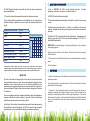
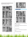
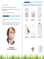
Congratulations!
You've just purchased a new Marey ECO110 tankless water heater and
will soon begin to enjoy the benefits of “going tankless.”
Take the time to thoroughly read and understand this safety and installation
manual in its entirety before you attempt to install your new ECO110 tankless
water heater, as it contains important safety tips andinstructions.
Please carefully read all instructions and warnings. Should you have any
questions, please visit www.marey.com for installation videos and FAQ.
Please keep this manual for future reference.
02
WARNING
04
INSTALLATION GUIDE
04
INSTALLATION
04
RESTRICTIONS
06
ENERGY SAVING TIPS
07
OTHER POWER REQUIREMENTS
07
QUICK INSTALLATION GUIDE
09
HOW TO USE
09
STEPS TO RESET THE HEATER
11
CUSTOMER SERVICE
12
OTHER PRODUCTS
13
03
If your water heater requires a reset, be sure to TURN OFF THE BREAKER prior to
resetting the unit.
Resetting your unit without turning off the breaker can result in personal injury and
damage to your water heater.
WARNING! There is water contained in the coils of your water heater at all times. If your
water heater is exposed to freezing temperatures, the water in the coils could freeze,
causing a break in the heat exchanger of the unit, or the supply and return lines. This kind of
damage will result in water running freely into the space where the water heater is located,
with can cause flooding. DO NOT install this water heater where it may be subjected to a
freeze. If your water heater is in an area where freezing is a possibility, you must turn off the
water to the heater and drain it of any water by disconnecting the water lines. Leave the
water lines disconnected until you intend to use the water heater.
IMPORTANT: Working with electricity requires proper skills and knowledge–and
work should NOT be performed by someone who is not trained in this trade. We
HIGHLY recommend that you solicit the services of a licensed and qualified
“Electrician/Plumber”familiarwithtankless water heater installation.
IMPROPER INSTALLATION CAN CAUSE INJURY OR EVEN DEATH.
Absolutely no electrical wiring connections should be made to this unit until the unit
has been properly secured to the wall. Absolutely no connections should be made to
this unit until all external electrical work has been completed.
I) HANGING THE UNIT
- The heater must beinstalled vertically and secured with 3 screws using the“drill
hole template” included with this heater.
- Do not connect power or water prior to properly hanging the unit.
- Mark the position of the points of the 3 screws using the template supplied.
Note that we re commend leaving 6 inches clearance (free) around the heater,
therebyfacilitatingthe proper installation and maintenance.
II) PLUMBING
Important: Your ECO110 water heater does NOT have a high pressure relief
valve. Your heater is intended for use ONLY up to 150 PSI of water pressure. When
water pressures may exceed 150 PSI, you MUST install a pressure relief valve
adjacent to the cold water entrance.
The heater should be installed as close as possible to the point of use. The
further the hot water has to travel, the higher the likelihood of heatloss.
Do not install in wet areas.
When installed in a location that could freeze the heater must be isolated and
drained.
- Stainless steel flexible hose or copper tubing must be used. Do NOT use PVC,
CPVC, or other plastic supply lines to connect the unit. The copper or steel must
run a minimum of 16” from the heater before any other type of tubing or pipe can be
used.
- Your unit comes prefitted with a 1/2” NPT adapter. Connect 1/2” stainless steel
hose or ½” threaded copper to connect to the unit. (Cold water inlet is on the right
side of the unit, hot water outlet is on the left.)
-You must use an isolation valve at the inlet pipe of the unit, to allow the water to the
unit to be shut off without turning off water to the whole house. Connect the
isolation valve at the entry inlet pipe of the heater and make sure you install a
rubber washer. Do not apply excessive force to tighten connectors.
-Flush the water lines with water to clear any debris or impurities before attaching to
the unit.
-Any residue or dirt in the pipes may cause internal damage to the unit. We
recommend installing a sediment filter before the entry of water to the heater. Hard
water or water with high levels of minerals and alkali can cause damage to this unit.
When this is the case, we recommend the use of a (non-salt) water softening
system.
-Check for water leaks and correct as necessary before applying power to the unit.
- Install screws at the marked locations. If you are installing in sheetrock, use the
provided wall anchors by drilling a ¼” hole. Install the anchors before installing the
screw. Otherwise,directly attach screws to studs.
-Hang the heater from the screws using the keyhole brackets on the back of the
heater.
04
III) ELECTRICITY
- Install a 50 Amp GFCI fuse box or switch (“breaker") for exclusive use of the
heater. Wire size will vary based on distance, but this unit will require a MINIMUM
size of 8 AWG wire.
05
IMPORTANT: THE BREAKER MUST BE GFCI. THE UNIT DOES NOT HAVE
AN INTERNAL GFCI CONTROL! FAILURE TO USE A GFCI BREAKER CAN
RESULT IN INJURY OR DEATH.
-Connect the ground, as indicated in the Electrical Code.
-Allow water to flow through the unit for several minutes before applying power to
unit. Identify and correct leaks as necessary.
- This unit requires a single dedicated circuit. NO other equipment can be on this
circuit.
- Turn off the power switch when the unit will be unused for extended periods of
time.
- Installation must be performed by a certified electrician.
NOTE: Improper use or installation will void the warranty.
- IMPORTANT: The internal heating coils are submerged in a small reservoir
inside your heater. These tanks MUST be full of water before applying power for
proper function. If the water supply is ever disconnected from the unit, ALWAYS
run the water with the faucet fully open for one or two minutes prior to reapplying
power.
Remember: Run the water before turning on electricity.
NOTE: The electrical supply should never be turned on until installation is
complete.
- When possible, install the heater in the most central location, nearest to the point
of use (where hot water is needed, e.g., shower, faucets, etc.)
- Adjust heater temperature settings (located on the front panel of the heater) to the
desired output temperature you desire. Use the lowest comfortable setting for
optimal energy savings.
- We recommend that you install the unit under the sink in main bathrooms or utility
areas. This will allow for the minimum power consumption and will reduce the
possibility of heat loss due to longer pipe runs.
- DO NOT expose the unit to freezing temperatures. Do not use when cold water
input water temperatures exceed 90 degrees F or 32.2 degrees Celsius.
- DO NOT restrict the flow of water entering the unit.
- For additional savings, reduce the water flow valve at the inlet of the heater to the
minimum comfortable setting. The slower the flow through the unit, the more
heating it's capable of.
- DO NOT use the unit if water ceases to flow during use.
- If the outer case or cover is loose, your heater will not work correctly. An
improperly secured cover can cause injury or electric shock.
WARNING! THIS APPLIANCE MUST BE PROPERLY GROUNDED!
- This unit is designed for indoor use only.
1. The heater should only be connected to a supply 208/240VAC.
NEVER OPERATE THIS HEATER WITHOUT THE COVER!
2. The heater must be connected to its own independent electrical circuit.
WARNING: When power is applied, this unit can produce extremely hot water!
Take proper safety precautions to avoid being hurt or be burned by water. ALWAYS
test water temperature with your hand before showering.
3. Confirm that you have sufficient power available to operate the unit prior to
installation. Contact your electric company if you aren't sure of your service
amperage.
- Ensure that all electrical connections are adequately protected by GFCI to
prevent shock, overheating and damage. IMPORTANT: The fuse does not give
personal protection against electric shock. A single 50 Amp ground fault breaker
(GFCI) or a residual current device (RCD) MUST be installed on this circuit.
4. The switch must be accessible and clearly identifiable.
06
5. Do NOT operate the settings or power on the unit with wet hands or while
standing in water. Severe injury or death can result. We STRONGLY recommend
that the unit be located out of reach of a person who is in the shower or bath.
07
6. Do NOT hang the unit where it is possible for it to fall into water or where it may
be sprayed with water.
1. Use a MINIMUM #8 AWG wire for electrical connection.
depending on distance; see above for additional details).
7. The unit circuit should be separated from other circuits to prevent arcing.
2. CAUTION: Verify that the cables are tight.
8. It is essential that the conditions of each installation site are evaluated by a
qualified electrician to determine the correct cable size and permissible circuit
length.
3. Use the illustrated cardboard template to identify the location of the mounting
screws.
ECO110
Voltage
220V
Power
11kW
Amperage
44A
Frequency
50Hz - 60Hz
Wire Size
8 AWG
Activation Flow Rate
0.66 GPM
Maximmum Flow Rate
Min. / Max. Water Pressure
3 GPM
8 PSI - 150 PSI
Width x Height x Depth
7.5" x 10.8" x 3.1"
Weight
7 lbs
4. Install screws (with wall anchors if a stud is not available) in the marked
locations. Hang the unit from the screws using the keyhole brackets on the back of
the heater.
TEMP. INCREASE PER GPM
ECO110
GPM
TECHNICAL SPECIFICATIONS
(Or larger
1
2
3
4
1.0
8ºF 23ºF 39ºF 51ºF
1.25
7ºF 19ºF 33ºF 46ºF
1.5
7ºF 18ºF 28ºF 41ºF
2.0
5ºF 14ºF 25ºF 35ºF
2.5
4ºF 13ºF 23ºF 31ºF
3.0
-
8ºF 13ºF 17ºF
*Temperature increases listed are based on use of the water heater under optimal
conditions with an incoming water temperature of 48ºF. Variable factors such as incorrect or
imperfect installation or warmer incoming water temperature may yield different results.
IMPORTANT!
The size of the switch and wire gauge must meet all local, state, provincial and
national electrical codes in your area - these are just guidelines that apply to most
installations. Some codes require the use of electrical substations for the
installation panel, especially when heater is not mounted within line of sight of the
main electrical panel. Wiring must be sized to maintain a voltage drop of less than
3% under load.
There are real dangers involved in improper installation of any electrical appliance.
Improper installation will void the warranty of your unit. Failure to follow proper
installation procedures creates a risk of injury or death.
5. Install the ½” NPT connections for the cold and hot water. Use stainless steel
tubing or copper for at least 16” from the unit before adapting to PVC, CPVC, or
other plastic based material.
IMPORTANT: Avoid water spillage. If any water spillage occurs, dry completely
before applying power!
6. Open the water inlet valve of the heater. Check for and correct as necessary
ANY water leaks.
7. Allow water to run with the tap fully open for several minutes before connecting
power.
8. Connect power.
- Open the hot water tap and the tankless hot water heater will activate and begin
producing hot water.
-Test temperature with your hand before use. Mix hot with cold water to achieve
the desired output temperature.
- The speed of water passing through the unit will determine the amount of
temperature increase (for example, slowing the flow of water will increase the
temperature. A faster flow will result in a lower output temperature.) If you would
like the water to be hotter, slow down the flow through the unit with the isolation
valve. If you would like the water to be colder, open the valve to allow maximum
water flow.
Local Codes: Most counties, cities and states have specific local codes governing
the installation of electrical equipment. You MUST to know the code and permit
requirements in your community before installing your tankless water heater.
08
09
- In cooler regions or cooler seasons, the incoming water temperature can cause a
variation in the output temperature. The temperature settings on the unit allow you
to compensate for flow variations and seasonal changes.
Warning:If your water heater requires a reset, be sure to TURN OFF THE
BREAKER prior to resetting the unit.
Resetting your unit without turning off the breaker can result in personal injury and
damage to your water heater.
1. Disconnect power to the unit.
2. Unscrew the two screws that are at the bottom of the unit and which hold the
cover on.
3. Remove the temperature controller knob.
10
11
4. Remove the cover carefully.
Marey proudly manufactures water heaters and accessories for use in almost any
application. Please visit our website to learn more about other Marey products.
5. Open the hot water tap and let the water run about 10 seconds.
6. Tighten the two buttons indicated in the illustration (see Figure 6) and press
each one until it clicks.
7. Replace the cover and temperature controller knob.
At Marey, we pride ourselves on the excellence of our customer service and
support team.
ECO110
POWER PAK
SANTON
AQUAMATIC
GAS PORTABLE
POWER GAS
Please feel free to contact us if you have any questions about our products, warranty
service, or if you need assistance installing a unit. We also strive for continuous
improvement, so we welcome your comments, feedback and suggestions.
1-855-MAREY-55
[email protected]
Delbrey Street, 211
San Juan, Puerto Rico
00912
Tel: 1-512-332-2229
Toll Free: 1-855-627-3955
1-855-MAREY-55
www.marey.com
12
13