1
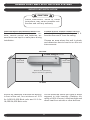
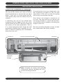
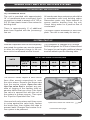
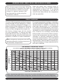
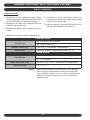
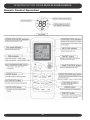
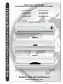
WALL SPLIT DUCTLESS
COOLING ONLY AND HEAT PUMP SYSTEMS
Cooling Only Models
HF-25GW/GX1B
HF-35GW/GX1B
HF-51GW/GX1A
HF-70GW/GX1A
Heat Pump Models:
HFR-25GW/GX1B
HFR-35GW/GX1B
HFR-51GW/GX1A
HFR-70GW/GX1A
9,000 Btu / 12,000 Btu
18,000 Btu
24,000 Btu
Harbor Point Air Conditioners
www.harborpointac.com
HARBOR POINT WALL SPLIT DUCTLESS SYSTEMS
INSTALLATION, OPERATION AND MAINTENANCE MANUAL
This manual is intended as an aid to a qualified service personnel for proper
installation, operation, and maintenance of Harbor Point Air high efficiency R-410A
Wall Split Ductless Systems. Carefully read these instructions before attempting
installation or operation. Failure to follow these instructions may result in improper
installation, operation, or maintenance, possibly resulting in fire, electrical shock,
property damage, personal injury, or death.
Shipping Damage MUST be Reported to the Carrier IMMEDIATELY!!!
Examine the carton for signs of damage if any is evident open packaging and
check the unit for shipping damage.
SAFETY INSTRUCTIONS
TO THE INSTALLER
(2) Before leaving the premises, review this
manual to be sure the unit has been
installed correctly and run the unit for
one complete cycle to make sure it
functions properly.
Read all instructions before using
the Harbor Point high efficiency
system. Install or locate this system only in accordance with these
instructions. Use this system only
for its intended use as described in
this manual.
To obtain technical service or warranty
assistance during or after the installation
of this unit, check our website at
www.harborpointac.com or call your
installing contractor or distributor. Our
technical service department may be
contacted at 1-888-908-9888.
Check rating plate for correct system
voltage before installing. Installation and operation of a system with
the incorrect voltage may result in
malfunction or other issues and will
void the warranty.
(1) Retain this manual for future reference.
When calling for assistance, please have
the following information ready:
The Harbor Point system must be
connected only to a properly
grounded electrical supply. Do not
fail to properly ground this unit.
• Indoor Unit
Model Number
Turn off the electrical supply before
servicing the Harbor Point system.
• Indoor Unit
Serial Number
Do not use the Harbor Point
system if it has damaged wiring, is
not working properly, or has been
damaged or dropped.
• Outdoor Unit
Model Number
• Outdoor Unit
Serial Number
[Save These Instructions]
• Date of installation
!
2
This symbol is an indication of
Important Safety Information.
!
HARBOR POINT WALL SPLIT DUCTLESS SYSTEMS
! DANGER !
INSTALLER SUPPLIED ITEMS
Tampering with the Harbor Point
system is dangerous and may
result in serious injury or death.
Tampering voids all warranties. Do
not attempt to modify or change
these units in any way.
• Main System Breaker: Sized per unit
requirements, to be mounted adjacent
to outdoor unit.
• Mounting Hardware: Wall anchors,
condenser pad.
• Vacuum Pump
• Gauge Set : R-410 specific.
PRODUCT DESCRIPTION
• High Voltage Interconnect Wiring:
The Harbor Point system is an efficient
14 AWG wiring from outdoor unit to inwall split ductless conditioning system
door unit for power and control. *
with cooling capacities from 9,000-24,000
Btu and heat pump capacity of 9,000- • Refrigerant : R-410A required for additional line sets beyond 16 ft.
24,000 Btu. Designed for quiet operation
and boasting compact dimensions, the
Harbor Point system includes advanced * Can be purchased through the factory as an
accessory, (part of the Tube Set Kit below)
features like auto-restart, full feature
remote control.
ACCESSORY
Comprised of three standard components Tube-Set Kit consisting of:
the indoor evaporator, the outdoor
• Refrigerant Line Set - 16.4 feet of
condensing unit, and an infrared handheld
suction and liquid line, both fully inremote control are engineered to the
sulated, and flare fittings supplied
highest performance and reliability. The
on both ends.
evaporator is equipped with permanent
washable air filters as well as motorized
• Interconnecting High Voltage Wiring
air sweep for enhanced air circulation,
-16.4 feet supplied.
and the condensing unit is equipped as
• Additional Condensate Tubing - 6 feet
standard with a high efficiency rotary
extra supplied.
compressor.
FACTORY SUPPLIED ITEM
Harbor point recommends the system for
residential and light commercial cooling
and heating applications and will operate • Matched System Consisting Of:
Evaporator section and condenser secin standard cooling mode down to 60°F
tion with remote control.
outdoor temperature.
ITEMS FOR CONSIDERATION
Application:
Check the application of the unit prior to
installation, certain applications require
additional components or installation parameters, such as the need for external
condensate pump or if the system will
need to perform low ambient cooling at
outdoor temperatures below 60°F.
3
HARBOR POINT WALL SPLIT DUCTLESS SYSTEMS
CHOOSING UNIT MODEL
MODELS OFFERED
Indoor Model #
Outdoor Model #
Duty
Capacity Btuh
Voltage
HF-25G/GX1b
HF-25G/GX1b
Cooling Only
9,000
115-1-60
HF-35G/GX1b
HF-35G/GX1b
Cooling Only
12,000
115-1-60
HF-51G/GX1a
HF-51G/GX1a
Cooling Only
18,000
208/230-1-60
HF-70G/GX1a
HF-70G/GX1a
Cooling Only
24,000
208/230-1-60
HFR-25G/GX1b
HFR-25G/GX1b
Heat Pump
9,000
115-1-60
HFR-35G/GX1b
HFR-35G/GX1b
Heat Pump
12,000
115-1-60
HFR-51G/GX1a
HFR-51G/GX1a
Heat Pump
18,000
208/230-1-60
HFR-70G/GX1a HFR-70G/GX1a
Heat Pump
24,000
208/230-1-60
4
HARBOR POINT WALL SPLIT DUCTLESS SYSTEMS
PRE INSTALLATION
Determine the best location for mounting
the indoor unit, it must be located a minimum of 4 ft (6 ft or more recomended) from
the floor and no less than 6” from ceiling.
CONTROLS AND COMPONENTS
Units are supplied with a wireless remote
control, which communicates with the unit
microprocessor control. The return air
temperature sensor mounted in the indoor unit provides input to the control for
system operation.
Pay attention to the air circulation in the
room, 9,000 & 12,000 Btuh units throw air
15ft, 18,000 & 24,000 Btuh units throw air
25ft, ensure no obstacles to airflow exist.
Several modes of operation are available
to the end user depending on the type of
comfort required. All unit operating functions are controlled via the remote control. Refer to “System Operation” section
of this manual.
Locate the indoor and outdoor units as close
together as possible, maximum line set run
and lift MUST NOT BE EXCEEDED. Determine how the interconnect piping, wiring
and condensate hose are to be run.
HF-25/HF-35
50 Feet
Max
Vertical
Lift
17 Feet
HF-51/HF-70
50 Feet
17 Feet
HFR-25/HFR-35
50 Feet
17 Feet
HFR-51/HFR-70
50 Feet
17 Feet
Unit
Max Line
Set Run
OPTIONAL CONTROLS AND
COMPONENTS
Low Ambient Control:
Please consult the factory for availability of
approved method of low ambient cooling
operation.
Condensate Pump:
It is recommended to use the supplied
condensate drain hose in a gravity fed
method whenever possible. If this can
not be done then a field installed pump
that is external to the evaporator would
be required.
Ensure that all panels can be removed for
service as required.
Certification:
All Harbor Point Systems are certified by
UL under UL Standard 1995. Performance is varified by CSA under ARI
210/240 test standard.
5
HARBOR POINT WALL SPLIT DUCTLESS SYSTEMS
INDOOR UNIT INSTALLATION
!
CAUTION
!
Follow Instructions, failure to follow
instructions may cause possible malfunction and void any warranty.
Remove indoor and outdoor units from
the carton/box. Indoor unit carton contains, remote control and batteries, ensure these are kept in a safe place during
installation.
Locate area to install indoor unit the
unit should be located a minimum of 6 ft.
from the floor and 6” from the ceiling.
Choose an area where the wall is plumb
and determine how to best to run the unit
interconnects.
CEILING
6” from ceiling m
minimum
8”
from wall
minimum
8”
from wall
minimum
4ft from floor (minimum)
6ft plus from floor (optimum)
FLOOR
Ensure no obstacles to airflow are directly
in front of the unit, for a minimum of 12 ft
for 9,000/12,000 Btuh units and 16 ft for
18,000/24,000 Btuh units.
Do not install the Indoor unit units in areas
exposed to high humidity (Relative Humidity of 80% or more), direct sunlight and
direct heat from stoves or other devices.
6
HARBOR POINT WALL SPLIT DUCTLESS SYSTEMS
INDOOR UNIT INSTALLATION
Prepare the evaporator for mounting
by removing the mounting bracket from
the rear of the indoor unit. Use a Phillips
head screwdriver to remove the unit pipe
strap. If the unit is a heat pump the defrost sensor also must be undone from its
retainer.
If mounting the unit on an inside wall, use
the knockouts provided on the left and
right sides of the unit to route the piping
and wiring connections through.
The indoor unit weighs a maximum of
20 Lbs. Use wall anchors to secure the
mounting bracket to a wall stud and ensure that the wall is capable of holding the
weight of the unit.
If mounting the unit on an outside wall
measure from the edges of the unit to the
center of the line set 90° bend to locate the
the center of the wall penetration. Drill a
3” ø hole through the wall. Angle the wall
penetration slightly down towards the outside to assist in draining the condensate
away from the unit.
knockout
Be sure mounting bracket is level, so that
the condensate can drain properly.
remove mounting bracket
mounting
bracket
on wall
knockout
3” ø hole
Note: Prepare all wiring and piping
connections before hanging the unit
on the mounting bracket.
7
HARBOR POINT WALL SPLIT DUCTLESS SYSTEMS
INDOOR UNIT INSTALLATION
Prepare unit line set connections
Rotate refrigerant line stubs gently to 90°
(if mounting on an outside wall). For other line set configurations align the stubs
as required.
Feed the 14 AWG interconnect wiring
between indoor and outdoor through
the unit electrical connection (maximum number of 6 wires is required) (if
required by local codes an electrical
connector can be attached to the rear
of the unit). Tape the loose wire to the
line set stubs. (See Electrical Wiring Install section.) These two tips save time
and prevent damage to the stubs when
mounting the indoor unit.
Tip: Use Duct tape to tape the Condensate hose (make sure it is below
the Line set stubs) and the defrost
sensor (heat pump only). This makes
it easier to guide them through the
hole in the wall.
HEAT PUMP SYSTEMS
Very Important! Make sure the defrost sensor wire is run and connected
between the indoor and outdoor units,
or the heat pump system will not operate in heat mode. Refer to “Heat Pump
Wiring” section of this manual.
duct tape
8
HARBOR POINT WALL SPLIT DUCTLESS SYSTEMS
INDOOR UNIT INSTALLATION
Install unit on mounting bracket
Feed the line set stubs/condensate hose/
wiring connections through a ø 3” hole in
the wall.
Position the evaporator so that the “key”
slots on the back of the unit slide onto the
tabs on top of the mounting bracket. Then
push the lower portion of the evaporator
against the bracket until it latches into the
mounting bracket.
18,000 Btuh shown
through the wall penetration, also check
that the wall is plumb. The unit must be
level and plumb for proper condensate
removal.
Indoor unit is now installed, it should be
plumb, level and flush with the wall. Insure that the line set stubs are completely
OUTDOOR UNIT INSTALLATION
Locate Outdoor unit
Select a location with proper ventilation,
minimizing recirculation possibility. Do not
install the outdoor unit in a location exposed to high winds (field fabricated and
installed wind baffle may be required).
Ensure location does not impede access
around unit and pose a disturbance to
neighboring areas.
Install the outdoor unit on a condenser
service pad. If unit is a heat pump extend feet to raise 6” to allow for defrost
to drain away.
Clearances for the Outdoor unit:
12” Minimum
Rear
Service
Valves
Outdoor Unit
12” Minimum
Front
Condenser Fan
Airflow
48” Minimum
Note: Consult factory if
minimum clearances can’t
be maintained.
9
12” Minimum
HARBOR POINT WALL SPLIT DUCTLESS SYSTEMS
Refrigerant Line Set Piping
Interconnecting line set between the
outdoor unit and the indoor unit, must have
both refrigerant lines insulated as the
expansion device is located in the outdoor
unit.
Gently bend the line set stubs from the
in- door unit to the desired location.
Using 2 x 10”/12” Crescent wrenches
remove the flare nuts from the indoor
unit line stubs.
The indoor unit is filled with a dry
gas, check for release of this to ensure
that no leaks are present. Use a small
amount of vacuum pump oil on the male
flare threads to ease installation.
Connect the line set to the stubs.
Using the 2 wrenches, 1 on the male
and 1 on the female tighten the flare
nuts. Run the line set to the outdoor
unit, avoid tight bends and kinking
the lines.
If line set length is in excess of that
re- quired, cut line set and re-flare or
coil ex- cess vertically to facilitate oil
return to the compressor.
Service port
Gas line service valve
Line set connections
under the GRAY
caps.
Outdoor
Unit
Liquid line service valve
9,000/12,000 shown
18,000/24,000 has additional
liquid line port
remove line
set cover
Indoor Unit
Install the line set on the
indoor unit stubs.
10
HARBOR POINT WALL SPLIT DUCTLESS SYSTEMS
OUTDOOR UNIT INSTALLATION
Evacuation
Gauges can now be attached to the service
ports - SERVICE PORTS HAVE A 5/16”
CONNECTION TO GAUGES, which is different from the norm for R-22. You will need
specific hoses or an adaptor for the 5/16”
connection.
tem to remove all traces of moisture. See
“System Start-Up” section to fine-tune the
refrigerant charge.
Main Power Wiring
Electrical wiring should be done in accordance with all National Electrical Code
(NEC) and local state/city building codes.
Once the gauges are attached the line
set can be leak checked using Nitrogen
at 300 psig. Evacuate the unit and interconnect down to a minimum of 400-500
Microns, break vacuum with Nitrogen to
further leak check.
Note: A small screwdriver is required
for unit terminals.
Breaker size and wiring must be sized
for the rating plate amperage, MCA and
HACR. Use only HACR type breakers,
each system installed must have a separate branch circuit with an individual
breaker/fuse.
Re-evacuate the system down to 300-400
Microns or lower for a period of one hour.
This is an R-410A System it is essential
that a deep vacuum be pulled on the sys-
Electrical Specifications
Nominal
Capacity
Btuh
Compressor
Volts/Hz/Ph
9,000
Cond Fan
Watts
RLA
Indoor Fan
Watts
RLA
Total
FLA
MCA
HACR
Max
Fuse
RLA
LRA
115/60/1
7.5
47
35
0.81
16
0.35
7.2
10.6
15.0
12,000
115/60/1
9.9
53
45
0.80
16
0.35
9.6
14.0
20.0
18,000
208/230/60/1
6.6
42
60
0.85
40
0.40
6.4
9.5
15.0
24,000
208/230/60/1
10.0
46
60
0.90
40
0.40
8.1
13.8
23.8
Cooling Models Only
Heat Pump Models Only
9,000
115/60/1
7.5
47
35
0.81
16
0.35
7.2
10.6
15.0
12,000
115/60/1
9.9
53
45
0.80
16
0.35
9.6
14.0
20.0
18,000
220/60/1
6.6
42
60
0.85
40
0.40
6.4
9.5
15.0
24,000
208/230/60/1
10.0
46
60
0.90
40
0.40
8.1
13.8
23.8
A local disconnect should be installed adjacent to the outdoor unit in accordance
with National and Local Codes. The outdoor unit provides power for the indoor
unit, no disconnect is required between
the outdoor and indoor units.
tion. Ground connection must be made to
the terminal plate.
Heat Pump (208/230 V) unit terminals:
L1 - L2 : Power from breaker + G
L3 - L4 : Power to indoor unit + G
1 - 2 - 3 : Control signals
Line voltage from the disconnect should
be wired to:
N - L (115V Unit), + G
L1 - L2 (208/230V Unit), + G
Remove right side knockout on the terminal access panel for whip/wiring connec-
These are just examples of typical wiring
connections. Always refer to Wire Diagram
on unit for actual wiring connections.
Tip: For easier access to the terminals in the
outdoor unit remove the lower access panel to
install whip and sealtite connectors for conduit.
11
HARBOR POINT WALL SPLIT DUCTLESS SYSTEMS
OUTDOOR UNIT INSTALLATION
Electrical Wiring Installation
!
CAUTION
outdoor unit must be a point to point i.e.
the terminal that the wire is attached to on
the outdoor unit must be the same terminal it is wired to in on the indoor unit.
!
Electrical Wiring should be done by a
certified electrician in accordance with
all National ElectricalCode (NEC) and
local state/city building codes.
THIS IS EXTREMELY IMPORTANT:
Switching the L3 - L4 or N1 - L1 wires
will allow the indoor unit to operate
but it will not provide controls signals
for the outdoor unit so that the compressor will not operate. Ground connection should be made to ground
screw marked in indoor unit.
ALL CONTROLS WIRING BETWEEN INDOOR AND OUTDOOR UNIT IS HIGH
VOLTAGE MINIMUM 14 AWG WIRE MUST
BE USED.
Remove terminal covers from indoor unit
and wire to the terminals, (small screwdriver required). Control wiring from the
COOLING ONLY WIRING
Control wiring at outdoor unit (cooling only).
Ground wires connected to the terminal
plate indoor and outdoor units must be
grounded.
Connection of wires for outdoor
unit and indoor unit
(115V Models)
Outdoor
unit
1
L1 N1
Indoor
unit
1
L1 N1
L N
T o power
source
(cooling only model)
(208/230V Models)
Outdoor
unit
1
L3 L4
L1 L2
�
Indoor
unit
1
L3 L4
To power
source
(cooling only model)
12
HARBOR POINT WALL SPLIT DUCTLESS SYSTEMS
OUTDOOR UNIT INSTALLATION
HEAT PUMP WIRING
If the system is a heat pump the defrost
sensor must be connected from the indoor unit to the defrost sensor in the outdoor unit. Standard lead length is 25 ft,
if a longer length is required then cut the
lead and extend using thermostat wire.
Note: use of colored wire (supplied with
line set) and defrost sensor connected
(heat pump only).
Indoor sensor connection
The heat pump defrost sensor interconnect wire comes bundled up with the indoor
units. It then should be “un-bundled” and
connected to the molex connection at the
indoor unit and run to the outdoor unit molex
connection, typically with the interconnecting wiring and/or interconnecting tubing.
Outdoor sensor connection
Defrost Sensor
Indoor wire connector
outdoor probe wire connector
for defrosting
Ground wires connected to the terminal plate on indoor and
outdoor units must be grounded.
Connection of wires for outdoor
unit and indoor unit
(115V Models)
Outdoor
unit
1 2 3 L1 N1
L N
�
Indoor
unit
To power
source
1 2 3 L1 N1
(heating model)
(208/230V Models)
Outdoor
unit
1 2 3 L3 L4
L1 L2
�
�
Indoor
unit
1 2 3 L3 L4
To power
source
(heating model)
13
HARBOR POINT WALL SPLIT DUCTLESS SYSTEMS
OUTDOOR UNIT INSTALLATION
12) Condensate Hose:
The unit is provided with approximately
18” of condensate hose connected. Hose
connection is sized to accept a 3/4” OD or
5/8” ID clear plastic hose to then extend to
building drain.
There is approximately 6’ of additional
drain hose supplied with the (accessory)
line set.
All condensate hose extensions should be
in accordance with local building codes.
Remember water only flows downhill to
ensure positive draining from the unit.
Check using water for a positive flow of
condensate.
The basic system installation is now complete. The unit is now ready for start up.
SYSTEM START UP
With the evaporator and line set completely
evacuated the system can now be opened
to allow the refrigerant charge in the outdoor unit to be released into the line set.
The condenser is charged with enough
R410A refrigerant for 25 feet of interconnect.
For longer line set lengths additional charge
must be added in per the following table.
UNITS
30 ft.
35 ft.
40 ft.
45 ft.
50 ft.
9000/12000 Btu
.3oz./ft.
1.5 oz.
3.0 oz.
N/A
N/A
N/A
18000/24000 Btu
.6oz./ft.
3.0 oz.
6.0 oz.
9.0 oz.
12.0 oz.
15.0 oz.
The service valves require a 6mm and a
5mm Allen wrench respectively to undo
the valve stems. Remove the brass caps
from the service valves. Open the suction line valve first to prevent any possible oil logging of the capillary tube expansion device that can occur if the liquid
line valve is opened first with the rest of
the system in a deep vacuum. Then open
the “Liquid or Expanded Gas” line.
Unscrew both valve stems until they come
to a stop against the valve body, replace
the brass caps, then tighten the caps to
prevent leaks. Energize the breaker to allow system to be powered.
Open the suction line valve first
Continued next page.
14
CHARGE
Charge oz.
per ft.
CHARGE
LINE
ADDED
CHARGE
REQUIRED
LINE
SETSET
ANDAND
ADDED
CHARGE
REQUIRED
HARBOR POINT WALL SPLIT DUCTLESS SYSTEMS
Start the indoor unit, cooling mode is
only allowed when the outside ambient
temperature is above 60° F to prevent
damage to the compressor. Unit has a 3
minute time delay before the compressor
start up operation.
Note: If interconnect is less then 25 feet
a small amount of refrigerant may need
to be reclaimed to achieve the proper
charge for optimal operation. We
recommends fine tuning using the
“Superheat” method.
FIELD CHARGING
The use of the superheat method is highly
recommended for field charging or checking the existing refrigerant charge in a
system that is in the cooling cycle. Because
each installation is different in terms of
indoor air flow, refrigerant line length, etc..,
the factory charge may not be correct
for every application. To assure the best
performance from the air-conditioner, the
refrigerant charge should be checked and
adjusted, if need be, on each installation.
Note: Refrigerant superheat is the temperature above the suction pressure at
its saturation temperature.
For proper superheat readings, a standard
low-side refrigerant gauge and an accurate
thermometer is needed. A mercury or
stem-type thermometer is not adequate
for suction-line temperatures. We recommend electric thermocouple thermometers
(available at most refrigeration wholesalers); however an accurate remote-bulb
thermometer can be used. When measuring the line temperature, be sure the thermometer is securely attached to assure
accurate measurements. The chart below
gives superheat values at various outdoor
temperatures. Allow at least 5 minutes running time between charge adjustments for
the unit to stabilize.
SUPERHEAT CHARGING CHART
50
45
SUPERHEAT °F
SUPERHEAT CHARGING CHART
Chart based on 360 to 400 CFM/ton indoor air flow and 50% relative humidity
Use on systems that cool with capillary or piston
40
90
35
85
30
Indoor dry bulb temperature °F
95
80
25
75
20
70
15
10
5
55
60
65
70
75
80
85
90
95
100
105
110
115
OUTDOOR TEMPERATURE °F
Note: If operating superheat is more than 5° F above the chart value, add refrigerant. If
below the chart value remove refrigerant. If below the limit line, remove refrigerant.
15
HARBOR POINT WALL SPLIT DUCTLESS SYSTEMS
FIELD CHARGING
Instructions:
1. Measure suction pressure and determine evaporator-refrigerant temperature
on R410A scale of low-side gauge.
2. Measure suction-line temperature on
suction line of the unit.
3. Measure outdoor and indoor temperatures.
4. Determine from the table what the
superheat should be for the indoor and
outdoor temperatures.
5. Adjust charge if needed. Be sure unit is
running at stabilized condition.
Example of typical system operations:
Cooling Cycle
80°F DB/50% RH Indoors
Conditions
82°F DB Outdoors
140 (49° F Saturated Temperature)
Return Gas Psig
Refer to supplied superheat chart (16° F)
Superheat
Heat Cycle
70° F Indoors
Conditions
47° F Outdoors
High Side Gas Psig
350/375 (107/112° F Saturated Temperature)
10 - 15° F
Sub-Cooling
Note:
When the system is in heat cycle, the refrigerant charge is checked by using the liquid subcool method. Liquid sub-cool is the temperature
below the high side pressure at its saturation
temperature.
16
OPERATION SECTION FOR
HF-25/HF-35 & HFR-25/HFR-35
.
Guide to features and their function
There are many models, features and appearance will vary. The figure shown is
representative of the operation of 9,000/12,000 Btuh systems.
Air return grill
Takes in the indoor air
Push down the air inlet grille and the push both sides of air inlet
grille at the bottom.
Lightly push both sides of the air inlet grille at the
botton and pull it to this side till a resistance is felt.
Note: Do not open the grille at an angle over 60 degrees.
17
OPERATION SECTION FOR HF-25/HF-35 & HFR-25/HFR-35
Remote Control Operation
This button, when pressed, starts operation
and stops when pressed again.
18
OPERATION SECTION FOR HF-25/HF-35 & HFR-25/HFR-35
Remote Control Operation
Note: Wait 3 minutes before restarting the unit.
Selecting MODE of OPERATION
To select operating mode, point the remote control
toward the indoor air conditioning unit:
1) Press the ON/OFF
2) Press the MODE
operating modes:
button to START.
button to step through the
AUTO MODE – automatically operates the system in DRY, COOL ,or HEAT mode depending on
the indoor temperature and setting.
COOL MODE – operates the system in COOL
mode depending on the indoor temperature and set
point.
DRY MODE – operates the system in DEHUMIDIFICATION mode.
HEAT MODE – operates the system in HEAT
mode depending on the indoor temperature and set
point.
Important:
Heating operation will cease at approximately
15° F outdoor temperature due to a sensor located in the outdoor unit. This product does not
contain supplemental electric heat, therefore
other means of heat need to used when this system ceases operation at low outdoor ambients.
FAN MODE – runs the FAN to circulate the air.
3) Press the ON/OFF button again to STOP.
19
OPERATION SECTION FOR HF-25/HF-35 & HFR-25/HFR-35
Remote Control Operation
Temperature adjustment in AUTO SELECT mode
To adjust the air temperature during AUTO SELECT
mode, point the remote control toward the indoor air
conditioning unit:
1) Press the
button once. To raise the set point
temperature 1°C or 1°F.
2) Press the
button once, to reduce the set
point temperature 1°C or 1°F.
COOL/HEAT & FAN/DRY mode
Point the remote control toward the indoor air conditioning unit:
1) Press the ON/OFF
button.
2) Press the MODE
button, select the mode of
operation; COOL, DRY, HEAT/FAN or AUTO.
3) Press the
perature.
or
to set the desired tem-
Heat
Cool
64°F- 88°F
(16°C-31°C)
64°F- 88°F
(16°C-31°C)
Once minimum or maximum setting is reached
operation will be continued by
pressing
or
4) Press the FAN SPEED
sired air flow rate.
Press the ON/OFF
button to set the de-
button again to stop.
Notes:
• In the COOLING-ONLY operation, the HEAT
mode will disable, and it will go to FAN mode.
• The settings can be changed even while the air
conditioner is off.
20
OPERATION SECTION FOR HF-25/HF-35 & HFR-25/HFR-35
Remote Control Operation
Up/down air flow direction adjustment
The up/down air flow direction can be adjusted by pressing the VANE CONTROL button
on the remote control, each time this button is pressed, the vane angle changes in the
following sequence:
(1)
(2)
(3)
(4)
(5)
(AUTO)
• (1) through (5) are fixed positions.
• AUTO oscillates up and down automatically.
Air flow velocity adjustment
To change the vane control velocity press the FAN SPEED button.
Each time the button is pressed, fan speed is changed in sequence,
[LO]
[MID]
[HI]
[AUTO]
To cool the whole room, use the
[HI] setting in COOL MODE. If the sound of the
air conditioner operating disturbs your sleep, use the SLEEP mode. (See next page)
Recommended horizontal VANE range
In
AUTO mode the VANE positions are
adjusted automatically.
In
(1)
COOL or
In
HEAT mode VANE positions (3)
(4)
or (2)
or (5)
DRY mode VANE positions
are recommended.
are recommended.
Note:
Left/right air flow direction adjustment
Adjust the air flow direction by hand,
move the air flow direction fins left/right to
direct the air as desired.
• In the cooling operation, when the air conditioner is operated with VANE CONTROL
blowing down (4) or (5) for 1 hour, the
VANE CONTROL direction is automatically
set to level to prevent condensed water
from dropping.
• Adjust the vertical VANE CONTROL direction using the remote control.
• In heating operation, if the output air temperature is too low or when defrosting is done,
the horizontal vane position is set to (1).
Swing adjustment (auto oscillation)
Press the SWING button, to adjust the air
swinging direction. Press the button again
to exit the SWING mode.
21
OPERATION SECTION FOR HF-25/HF-35 & HFR-25/HFR-35
Remote Control Operation
Setting the time
flashing
Back
Front
When batteries are inserted, the time will
automatically be set to 12:00 AM.
1) With the back cover off, press the CLK
button with the tip of a ball pen, etc. The
time indicator will flash, the time can now
be set.
AA Battery
AA Battery
clock button
2) Press the HOUR button to change the
hour. Example: (Set to 10:AM ) see front
view.
3) Press the MIN button to change the minutes. Example: (Set to 30) see front view.
Press
slide
cover
down to
remove
Press
to set
hours
4) When time is set press the CLK button
again. Slide the cover back, be sure it’s
clicked securely into place.
Press to set
minutes
Note: The timer is set on basis of the time on
the clock. Be sure to set the clock correctly.
Sleep mode
Sleep mode will reduce operation sound when
sleeping.
1) Press the SLEEP button to activate this
feature (air flow sound from the indoor unit
is decreased).
2) Press the SLEEP button again to release
the sleep mode or press the FAN SPEED
button during the SLEEP mode, and the
SLEEP mode is released
Press
SLEEP
button
Press
FAN
SPEED
button
Note: Use the sleep mode when you are
going to bed. If this mode is used during the
day, the capacity is reduced since the ambient temperature is higher. (COOL mode is
recommended for day use)
22
OPERATION SECTION FOR HF-25/HF-35 & HFR-25/HFR-35
Remote Control Operation
How to set the ON timer
1) Press the AUTO START button to set the
ON timer mode during operation. Each
time the button is pressed, the ON timer
mode alternates between ON and OFF.
2) Set the time on the timer using the HOUR
and MIN buttons.
• Each time the HOUR button is pressed,
the timer hours are increased by 1 hour.
• Each time the “MIN” button is pressed,
the timer minutes are increased by 10
minutes.
3) To release the ON timer, press the AUTO
START button again.
Press
AUTO
START
How to set the OFF timer
1) Press the AUTO STOP button to set the
OFF timer mode during operation. Each
time the button is pressed, the OFF timer
mode alternates beteen ON and OFF.
Press
to set
hours
Press to set
minutes
2) Set the time on the timer using the HOUR
and MIN buttons.
• Each time the HOUR button is pressed,
the set time is increased by 1 hour.
• Each time the “MIN” button is pressed,
the set time minutes are increased by
10 minutes.
3) To release the OFF timer, press the AUTO
STop button again.
Programming timer operation
The ON timer and OFF timer can be used in
combination. The set time which is reached
first will operate first (
mark indicates the
order of timer operations.)
Note: If the current time has not been set, the
timer operation cannot be accomplished.
23
OPERATION SECTION FOR HF-25/HF-35 & HFR-25/HFR-35
Features of Heating Operations
Important:
Heating operation will cease at approximately 15° F outdoor temperature due to a sensor located in the
outdoor unit. This product does not
contain supplemental electric heat,
therefore other means of heat need to
used when this system ceases operation at low outdoor ambients.
Defrosting
When the outdoor air temperature is very
low and humidity is very high, frosting will
occur in the heat exchanger of the outdoor
unit, which has negative impacts upon the
efficiency of the heating performance. In
this case, the automatic defrosting function
will come into play. The heating operation
will be stopped for 5-10 minutes to do the
defrosting.
Basic principles and performances
• The Heat Pumps absorb heat from the
outdoor air and transfers it indoors to
heat the indoor air. The heating capabilities through this principle go up/down
with the increase/decrease of the temperature of the outdoor air.
• When the outdoor air temperature is very
low, the system can be used together
with other heating devices. Good ventilation should be maintained to ensure
safety and prevent accidents.
• The fans of both the outdoor and indoor
units are stopped. During the defrosting
operation, the run light will flash slowly.
24
• During defrosting, the outdoor unit might
generate some steam. It is caused by
fast defrosting, which is not a performance failure.
• Upon the completion of the defrosting process, the heating operation is resumed.
OPERATION SECTION FOR
HF-51/HF-70 & HFR-51/HFR-70
Guide to features and their function
Air return grill
Takes in the indoor air
Push down the air inlet grille and the push both sides of air inlet grille
at the bottom.
Lightly push both sides of the air inlet grille at the
botton and pull it to this side till a resistance is felt.
Note: Do not open the grille at an angle over 60 degrees.
25
OPERATION SECTION FOR HF-51/HF-70 & HFR-51/HFR-70
Remote Control Operation
When timer is set this light is lit.
Air conditioner running light
Digital display
It can show set point temperature, fixed time
or malfunction code.
Fan speed indicator
In high speed, three indicators are lit.
In middle speed,two indicators are lit.
In low speed, one indicator is lit.
Note: The indicator may change, this does not affect the operation.
26
OPERATION SECTION FOR HF-51/HF-70 & HFR-51/HFR-70
Remote Control Operation
This button, when pressed, starts operation
and stops when pressed again.
(fixed direction)
This button is used for selection of the left/right air
flow direction, whenever pressed the flap changes
from osculating to fix, or from fixed to osculating.
When air-conditioner is cool-only model, the HEAT
mode is bypassed to FAN mode.
27
OPERATION SECTION FOR HF-51/HF-70 & HFR-51/HFR-70
Remote Control Operation
Note: Wait 3 minutes before restarting the unit.
Selecting MODE of OPERATION
To select operating mode, point the remote control
toward the indoor air conditioning unit:
1) Press the ON/OFF
2) Press the MODE
operating modes:
button to START.
button to step through the
AUTO MODE – automatically operates the system in DRY, COOL ,or HEAT mode depending on
the indoor temperature and setting.
COOL MODE – operates the system in COOL
mode depending on the indoor temperature and set
point.
DRY MODE – operates the system in DEHUMIDIFICATION mode.
HEAT MODE – operates the system in HEAT
mode depending on the indoor temperature and set
point.
Important:
Heating operation will cease at approximately
15° F outdoor temperature due to a sensor located in the outdoor unit. This product does not
contain supplemental electric heat, therefore
other means of heat need to used when this system ceases operation at low outdoor ambients.
FAN MODE – runs the FAN to circulate the air.
3) Press the ON/OFF button again to STOP.
28
OPERATION SECTION FOR HF-51/HF-70 & HFR-51/HFR-70
Remote Control Operation
Temperature adjustment in AUTO SELECT mode
To adjust the air temperature during AUTO SELECT
mode, point the remote control toward the indoor air
conditioning unit:
1) Press the
1°C or 1°F.
button once, to raise the set point
2) Press the
button once, to reduce the set
point temperature 1°C or 1°F.
COOL/HEAT & FAN/DRY mode
Point the remote control toward the indoor air conditioning unit:
1) Press the ON/OFF
button.
2) Press the MODE
button, select the mode of
operation; COOL, DRY, HEAT/FAN or AUTO.
3) Press the
perature.
or
to set the desired tem-
Heat
Cool
64°F- 88°F
(16°C-31°C)
64°F- 88°F
(16°C-31°C)
Once minimum or maximum setting is reached
operation will be continued by
pressing
or
4) Press the FAN SPEED
sired air flow rate.
Press the ON/OFF
button to set the de-
button again to stop.
Notes:
• In the COOLING-ONLY operation, the HEAT
mode will disable, and it will go to FAN mode.
• The settings can be changed even while the air
conditioner is off.
29
OPERATION SECTION FOR HF-51/HF-70 & HFR-51/HFR-70
Remote Control Operation
Up & down air flow direction adjustment
The up/down air flow direction can be adjusted by pressing the OUT FLAP button on
the remote control, each time this button is pressed, the vane angle changes in the
following sequence:
(1)
(2)
(3)
(4)
(5)
(AUTO)
• (1) through (5) are fixed positions.
• AUTO oscillates up and down automatically.
Air flow velocity adjustment
To change the vane control velocity press the FAN SPEED button.
Each time the button is pressed, fan speed is changed in sequence,
[LO]
[MID]
[HI]
[AUTO]
To cool the whole room, use the
[HI] setting in COOL MODE. If the sound of the
air conditioner operating disturbs your sleep, use the SLEEP mode.
Recommended horizontal VANE range
In
AUTO mode the VANE positions are
adjusted automatically.
In
(1)
COOL or
In
HEAT mode VANE positions (3)
(4)
or (2)
or (5)
DRY mode VANE positions
are recommended.
are recommended.
Horizontal & vertical auto swing
adjustment
Adjust the left to right air flow direction
with the remote control:
• Press the IN FLAP button, the air
swing fins will continually oscillate left
to right.
• Step through the diferent fins positions
using the IN FLAP button (fins can
also be set in a fixed position).
Note:
• In the cooling operation, when the air conditioner is operated with OUT FLAP blowing
down (4) or (5) for 1 hour, the OUT FLAP
direction is automatically set to level to prevent condensed water from dropping.
• Adjust the vertical OUT FLAP direction using the remote control.
• In heating operation, if the output air temperature is too low or when defrosting is done,
the horizontal vane position is set to (1).
30
OPERATION SECTION FOR HF-51/HF-70 & HFR-51/HFR-70
Remote Control Operation
Setting the time
flashing
Back
Front
When batteries are inserted, the time will
automatically be set to 12:00 AM.
1) With the back cover off, press the CLK
button with the tip of a ball pen, etc. The
time indicator will flash, the time can now
be set.
AA Battery
AA Battery
clock button
2) Press the HOUR button to change the
hour. Example: (Set to 10:AM ) see front
view.
3) Press the MIN button to change the minutes.
Press
slide
cover
down to
remove
Press
to set
hours
4) When time is set press the CLK button
again. Slide the cover back, be sure it’s
clicked securely into place.
Press to set
minutes
Note: The timer is set on basis of the time on
the clock. Be sure to set the clock correctly.
Sleep mode
Sleep mode will reduce operation sounds
when sleeping.
1) Press the SLEEP button to activate this
feature (air flow sound from the indoor unit
is decreased).
2) Press the SLEEP button again to release
the sleep mode or press the FAN SPEED
button during the SLEEP mode, and the
SLEEP mode is released
Press
SLEEP
button
Press
FAN
SPEED
button
Note: Use the sleep mode when you are
going to bed. If this mode is used during the
day, the capacity is reduced since the ambient temperature is higher. (COOL mode is
recommended for day use)
31
OPERATION SECTION FOR HF-51/HF-70 & HFR-51/HFR-70
Remote Control Operation
How to set the ON timer
1) Press the AUTO START button to set the
ON timer mode during operation. Each
time the button is pressed, the ON timer
mode alternates between ON and OFF.
2) Set the time on the timer using the HOUR
and MIN buttons.
• Each time the HOUR button is pressed,
the timer hours are increased by 1 hour.
• Each time the “MIN” button is pressed,
the timer minutes are increased by 10
minutes.
3) To release the ON timer, press the AUTO
START button again.
Press
AUTO
START
How to set the OFF timer
1) Press the AUTO STOP button to set the
OFF timer mode during operation. Each
time the button is pressed, the OFF timer
mode alternates beteen ON and OFF.
Press
to set
hours
Press to set
minutes
2) Set the time on the timer using the HOUR
and MIN buttons.
• Each time the HOUR button is pressed,
the set time is increased by 1 hour.
• Each time the “MIN” button is pressed,
the set time minutes are increased by
10 minutes.
3) To release the OFF timer, press the AUTO
STop button again.
Programming timer operation
The ON timer and OFF timer can be used in
combination. The set time which is reached
first will operate first (
mark indicates the
order of timer operations.)
Note: If the current time has not been set, the
timer operation cannot be accomplished.
32
HARBOR POINT WALL SPLIT DUCTLESS SYSTEMS
Features of Heating Operations
Important: Heating operation will cease at
approximately 15° F outdoor temperature
due to a sensor located in the outdoor unit.
This product does not contain supplemental electric heat, therefore other means of
heat need to used when this system ceases operation at low outdoor ambients.
Basic principles and performances
• The Heat Pumps absorb heat from the
outdoor air and transfers it indoors to
heat the indoor air. The heating capabilities through this principle go up/down
with the increase/decrease of the temperature of the outdoor air.
• When the outdoor air temperature is very
low, the system can be used together
with other heating devices. Good ventilation should be maintained to ensure
safety and prevent accidents.
Maintenance
Defrosting
When the outdoor air temperature is very
low and humidity is very high, frosting will
occur in the heat exchanger of the outdoor
unit, which has negative impacts upon the
efficiency of the heating performance. In
this case, the automatic defrosting function
will come into play. The heating operation
will be stopped for 5-10 minutes to do the
defrosting.
• The fans of both the outdoor and indoor
units are stopped. During the defrosting
operation, the run light will flash slowly.
• During defrosting, the outdoor unit might
generate some steam. It is caused by
fast defrosting, which is not a performance failure.
• Upon the completion of the defrosting process, the heating operation is resumed.
The air conditioner must be turned off before the maintenance is to be carried out.
Before the operating season
1) Check if there are any materials blocking the intake and outlet vents of the
indoor and outdoor units.
2) Check if the installation stand is corroded or rusty.
3) Check if the unit is properly grounded.
4) Check if the air filter is clean.
5) Connect to the power source.
6) Put batteries in the remote controller.
During the operating season
Check the air filter periodically during the
season and clean it if it is dirty.
Note: Do not open the grille to an angle over 60 degrees.
1) To remove the air filter screen from the unit.
• Gently press the two lower ends of
the grille and open it.
• Carefully lift the air filter screen up
and out pulling it toward you.
2) To Clean the air filter screen vacuum
it with a brush attachment (do not lift
the front cover more than 60°). If the
screen is very dirty, use lukewarm water (about 86°F or 30°C) to wash it. Air
dry after washing.
• Do not use boiling water to clean the
screen.
• Do not use exess heat or an open
fire to dry the screen.
• Do not exert too much force pulling
or stretching the screen.
3) Replace the air filter screen.
Do not operate the air conditioner
without the air filter screen. To do
so will cause dirt to collect on the interior of the unit which may lead to poor
performance and damage the unit.
Air filter screen
33
33
HARBOR POINT WALL SPLIT DUCTLESS SYSTEMS
Maintenance
To clean the surface of the air conditioner:
• Use a soft and dry cloth to wipe the
air conditioner off, or use a vacuum
cleaner to clean it.
• If the air conditioner is very dirty, use a
damp soft cloth with a neutral household detergent to clean the surface of
the unit.
Note: If the air filter screen is blocked
by dust or dirt, the performance of
cooling and heating will be affected,
and the operation noise and power
consumption will increased. Therefore, the air filter screen should be
cleaned regularly.
After the operating season
1) Set the temperature at 86°F or 30°C and
operate in the fan status for about half a
day, to dry out the interior of the units.
2) Stop the operation of the system
and turn OFF the power switch. The
air conditioner will consume about
5W of electric power after the unit
is turned off. For energy saving and
safety, it is advisable to disconnect
the power in the off season.
3) Clean and reinstall the air filter screen.
4) Clean the surface of both the indoor
and outdoor units.
5) Take the batteries out of the remote
control.
Troubleshooting
Check the following before requesting after-sale service from your dealer.
If the air conditioner does not operate at all
• Check if the main power is on.
• Is the time set to “ON” position?
(If using the timer function.)
• Check for a blown fuse or a power failure.
• Check the batteries in the remote control.
Poor cooling or heating performance
• Room temperature can’t be controlled
(Too cold or too hot ). Check if the room
temperature setting too low or too high.
• Are the air filters clean (Not clogged)?
• Are the window (s) and door (s) opened?
Poor cooling performance
• Check if direct sunlight is entering the room.
• Check if there is a heat source in the
room (i.e. - hot plate, oven, stove, etc).
• Are there too many people in the room?
If the air conditioner does not operate
properly ever after conducting the above
checks, if there is still doubt even after
consulting the Basic Operation Characteristics section on following page of this
manual, or in case of such phenomena as
described below, turn off the power and
contact your distributor.
Cases requiring immediate contact with the installer
Disconnect the power immediately, inform your installer in the following situations:
• Fuse or breaker often trips off (repeatedly).
• Remote does not initiate operation.
• Abnormal noise is heard during operation.
• If faulty operation is observed when
the RUN button is pressed and even
after restarting the operation after 3
minutes, faulty operation does not
disappear.
34
HARBOR POINT WALL SPLIT DUCTLESS SYSTEMS
Basic Operation Characteristics
Problem
Cause
The unit can not be restarted just after
shut down. (RUN light is on)
Restart is delayed for 3 minutes after shut
down to protect the unit.
Three-minute protection timer incorporated
in the microcomputer actuates automatically.
Except when power is connected, this function
does not actuate.
Air does not blow out at starting of heating operation.
Air circulation is stopped to prevent blowing
cold air into the room until heat exchanger
warms up. ( 2 to 5 min )
Heat pump system ceases operation in
heating mode.
Check to see if outdoor temperature is below
15° F. If so, operation will not resume until the
outdoor temperature rises above 17° F.
Air is not blown out for 6 to 12 min, at
heating operation.
When outdoor temperature is low and
humidity is high, the unit sometimes performs defrosting automatically.
Please wait. During defrosting, water or steam
may be seen coming from the outdoor unit.
Air is not blown out at DRY operation.
Indoor fan is sometimes stopped to prevent
vapor of dehumidified moisture and save
energy .
Mist is blown out at COOL operation.
This phenomenon sometimes occurs when
the temperature and humidity of the room
are very high. It will disappear with the lowering of the temperature and humidity.
Noise or cracking sound.
This is caused by the refrigerant that is circulating inside the unit.
Noise is heard (cracking sound). After a
power outage or after disconnecting the
power supply plug.
This is caused by heat expansion or contraction of plastics.
Operation can not be restarted even if
the power is restored.
The memory circuit of the microcomputer is
cleared. Operate the remote controller again
to restart the operation.
Remote control signals are not received.
Remote control signals may not be received when signal receiver on the air conditioner body is exposed to direct sunlight
or strong lighting. Interrupt the sunlight or
dim the lighting.
Moisture may form on the air outlet
grilles.
If the unit is operated for a long period of
time with the high humidity, moisture may
form on the air outlet grilles and drip down .
35