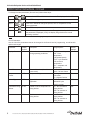
1
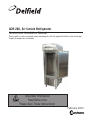
ACR-26S, Air Curtain Refrigerator Service and Installation Manual Please read this manual completely before attempting to install this equipment! Notify carrier of damage! Inspect all components immediately. Important Information Read Before Use Please Save These Instructions! February 2013 Air Curtain Refrigerator Service and Installation Manual Important Warning And Safety Information WARNING Read This Manual Thoroughly Before Operating, Installing, Or Performing Maintenance On The Equipment. WARNING Failure To Follow Instructions In This Manual Can Cause Property Damage, Injury Or Death. WARNING Do Not Store Or Use Gasoline Or Other Flammable Vapors Or Liquids In The Vicinity Of This Or Any Other Appliance. WARNING Unless All Cover And Access Panels Are In Place And Properly Secured, Do Not Operate This Equipment. WARNING This Appliance Is Not Intended For Use By Persons Who Lack Experience Or Knowledge, Unless They Have Been Given Supervision Or Instruction Concerning Use Of The Appliance By A Person Responsible For Their Safety. WARNING This Appliance Is Not To Be Played With. Warning Do Not Clean With Water Jet. WARNING Do Not Use Electrical Appliances Inside The Food Storage Compartment Of This Appliance. CAUTION Observe the following: 2 • Minimum clearances must be maintained from all walls and combustible materials. • Keep the equipment area free and clear of combustible material. • Allow adequate clearance for air openings. • Operate equipment only on the type of electricity indicated on the specification plate. • Unplug the unit before making any repairs. • Retain this manual for future reference. For customer service, call (800) 733-8829 or (800) 733-8948, Fax (989) 773-3210, www.delfield.com Air Curtain Refrigerator Service and Installation Manual Contents Receiving And Inspecting . . . . . . . . . . . . . . . . . . . . . . . . . . 3 Serial Number Location . . . . . . . . . . . . . . . . . . . . . . . . . . . . 4 Warranty Information . . . . . . . . . . . . . . . . . . . . . . . . . . . . . . 4 Regulatory Certifications . . . . . . . . . . . . . . . . . . . . . . . . . . . 4 Specifications . . . . . . . . . . . . . . . . . . . . . . . . . . . . . . . . . . . . 5 Installation . . . . . . . . . . . . . . . . . . . . . . . . . . . . . . . . . . . . . . 5 Operation . . . . . . . . . . . . . . . . . . . . . . . . . . . . . . . . . . . . . . . 5 Maintenance . . . . . . . . . . . . . . . . . . . . . . . . . . . . . . . . . . . . . 6 ERC2 Control Instructions Programming . . . . . . . . . . . . . . . . . . . . . . . . . . . . . 7-10 Error Codes . . . . . . . . . . . . . . . . . . . . . . . . . . . . . . . . 11 Wiring Diagram . . . . . . . . . . . . . . . . . . . . . . . . . . . . . . . . . 12 Replacement Parts . . . . . . . . . . . . . . . . . . . . . . . . . . . . . . . 13 Notes . . . . . . . . . . . . . . . . . . . . . . . . . . . . . . . . . . . . . . 14-15 Receiving and Inspecting the Equipment Even though most equipment is shipped crated, care should be taken during unloading so the equipment is not damaged while being moved into the building. 1. Visually inspect the exterior of the package an skid or container. Any damage should be noted and reported to the delivering carrier immediately. 2. If damaged, open and inspect the contents with the carrier. 3. In the event that the exterior is not damaged, yet upon opening, there is concealed damage to the equipment notify the carrier. Notification should be made verbally as well as in written form. 4. Request an inspection of the concealed equipment. This should be done within 10 days from receipt of the equipment. 5. Check the lower portion of the unit to be sure legs or casters are not bent. 6. Also open the compressor compartment housing and visually inspect the refrigeration package. Be sure lines are secure and base is still intact. 7. Freight carriers can supply the necessary forms upon request. 8. Retain all crating material until an inspection has been made or waived. Uncrating the Equipment First cut and remove the banding from around the crate. Remove the front of the crate material, use of some tools will be required. If the unit is on legs remove the top of the crate as well and lift the unit off the skid. If the unit is on casters it can be "rolled" off the skid. For customer service, call (800) 733-8829 or (800) 733-8948, Fax (989) 773-3210, www.delfield.com 3 Air Curtain Refrigerator Service and Installation Manual Serial Number Information To view the serial number of the ACR-26S refrigerator, open the door of the unit. The serial number is located on the inside back wall in the top left corner of the unit. Always have the serial number of your unit available when calling for parts or service. A complete list of authorized Delfield parts depots can be found on www.delfield.com. ©2013 The Delfield Company. All rights reserved. Reproduction without written permission is prohibited. Warranty Information Visit http://www.delfield.com/minisite/service/warranty_info to: • Register your product for warranty. • Verify warranty information. • View and download a copy of your warranty. Regulatory Certifications All models are certified by: National Sanitation Foundation (NSF) Underwriters Laboratories (UL) Underwriters Laboratories of Canada (ULC) 4 For customer service, call (800) 733-8829 or (800) 733-8948, Fax (989) 773-3210, www.delfield.com Air Curtain Refrigerator Service and Installation Manual Specifications Model ACR-26S V/Hz/Ph Amps Volume 18"x26" Tray Capacity H.P. 404A Charge BTU/Hr Door Closed BTU/Hr System Cap. 115/60/1 14.0 12.5ft3 10 1/2 32oz 504 3300 Ship Weight 592lbs/ 269kg NEMA Plug 5-20P Installation Location Electrical connection Leveling Reversing the door hinging The ACR-26S is intended for indoor use only. Be sure the location chosen has a floor strong enough to support the total weight of the cabinet and contents. Reinforce the floor if necessary to provide for maximum loading. Avoid placing unit under air conditioning vents or other ventilation fans that may affect the air curtain when door is open. A level cabinet looks better and will perform better because the doors will line up with the door frames properly, the cabinet will not be subject to undue strain, and the contents of the cabinet will not move around on the shelves. Use a level to make sure the unit is level from front to back and side to side. Stabilizing The ACR-26S is supplied with casters for your convenience, ease of cleaning underneath and for mobility. Two locking casters allow you to stabilize the unit if you are loading or unloading product. Refer to the amperage data shown in this manual, the serial tag and your local code or the National Electrical Code for proper wire sizes. All case wiring is labeled with the required voltagebe sure it is connected to the proper power source. A protected circuit of the correct voltage and amperage must be run for connection of the line cord or permanent connection to the unit. The following steps will allow you to reverse the side the door hinges on. 1. Open the door to 180° open position. 2. Lift up door and remove door from hinges in fully open position. 3. Remove pins from hinges. 4. Remove both hinges and relocate on the opposite side. Tighten hinges. 5. Unscrew the lock stop tab from the top of door and mount to the bottom in the holes provided. 6. Invert the door and mount it into the hinges in the fully open position. Operation When the door is open, Delfield’s patented air curtain design directs cold air across the cabinet opening, keeping hot air out and cold air in for two hours at a time. The unit will maintain a maximum of 45°F box temperature at 70°F ambient with the door open during peak production times, quickly returning to a normal 36°F. With the door closed, a maximum 40°F at 100°F ambient is maintained (normal operation) while running only 15% in an 85° room. Don’t pack the interior of the refrigerator so full that air cannot circulate. When operating open, keep shelves filled with trays and trays pushed all the way in so that they do not disrupt the air curtain air flow. Open the ACR’s door completely and the magnetic strip built in to the frame allows the door to remain open while loading or unloading. The power switch should be turned to the OFF position and the power cord disconnected whenever performing maintenance functions or cleaning the refrigerated cabinet area. For customer service, call (800) 733-8829 or (800) 733-8948, Fax (989) 773-3210, www.delfield.com 5 Air Curtain Refrigerator Service and Installation Manual Maintenance Door Gasket Maintenance Door gaskets require regular cleaning to prevent mold and mildew build up and also to retain the elasticity of the gasket. Gasket cleaning can be done with the use of warm soapy water. Avoid full strength cleaning products on gaskets as this can cause them to become brittle and crack. Never use sharp tools or knives to scrape or clean the gasket. Gaskets can be easily replaced and do not require the use of tools or an authorized service person. The gaskets are “Dart” style and can be pulled out of the groove in the door and new gaskets can be “pressed” back into place. Caster Maintenance Wipe casters with a damp cloth monthly to prevent corrosion. The power switch must be turned to OFF and the unit disconnected from the power source whenever performing service, maintenance functions or cleaning the refrigerated area. Refrigerators and Freezers The interior and exterior can be cleaned using soap and warm water. If this isn’t sufficient, try ammonia and water or a nonabrasive liquid cleaner. When cleaning the exterior, always rub with the “grain” of the stainless steel to avoid marring the finish. Do not use an abrasive cleaner because it will scratch the stainless steel and can damage the breaker strips and gaskets. Stainless Steel Care and Cleaning To prevent discoloration or rust on stainless steel several important steps need to be taken. First, we need to understand the properties of stainless steel. Stainless steel contains 70- 80% iron, which will rust. It also contains 12-30% chromium, which forms an invisible passive film over the steel’s surface, which acts as a shield against corrosion. As long as the protective layer is intact, the metal is still stainless. If the film is broken or contaminated, outside elements can begin to breakdown the steel and begin to form discoloration or rust. Proper cleaning of stainless steel requires soft cloths or plastic scouring pads. NEVER USE STEEL PADS, WIRE BRUSHES OR SCRAPERS! Cleaning solutions need to be alkaline based or non-chloride cleaners. Any cleaner containing chlorides will damage the protective film of the stainless steel. Chlorides are also commonly found in hard water, salts, and household and industrial cleaners. If cleaners containing chlorides are used be sure to rinse repeatedly and dry thoroughly. Routine cleaning of stainless steel can be done with soap and water. Extreme stains or grease should be cleaned with a non-abrasive cleaner and plastic scrub pad. Always rub with the grain of the steel. There are stainless steel cleaners available which can restore and preserve the finish of the steels protective layer. Early signs 6 of stainless steel breakdown are small pits and cracks. If this has begun, clean thoroughly and start to apply stainless steel cleaners in attempt to restore the passivity of the steel. Never use an acid based cleaning solution! Many food products have an acidic content, which can deteriorate the finish. Be sure to clean the stainless steel surfaces of ALL food products. Common items include, tomatoes, peppers and other vegetables. Cleaning the Condenser Coil In order to maintain proper refrigeration performance, the condenser fins must be cleaned of dust, dirt and grease regularly. It is recommended that this be done at least every three months. If conditions are such that the condenser is totally blocked in three months, the frequency of cleaning should be increased. Clean the condenser with a vacuum cleaner or stiff brush. If extremely dirty, a commercially available condenser cleaner may be required. Failure to maintain a clean condenser coil can initially cause high temperatures and excessive run times. Continuous operation with a dirty or clogged condenser coil can result in compressor failure. Neglecting the condenser coil cleaning procedures will void any warranties associated with the compressor and cost to replace the compressor. Never use a high-pressure water wash for this cleaning procedure as water can damage the electrical components located near or at the condenser coil. Doors/Hinges Over time and with heavy use doors the hinges may become loose. If this happens tighten the screws that mount the hinge brackets to the frame of the unit. Loose or sagging doors can cause the hinges to pull out of the frame, which may damage both the doors and the hinges. In some cases this may require qualified service agents or maintenance personnel to perform repairs. Preventing blower coil corrosion To help prevent corrosion of the blower coil, store all acidic items, such as pickles and tomatoes, in sealable containers. Immediately wipe up all spills. Continuous opening and closing of the doors will hamper the unit’s ability to maintain optimum refrigeration temperature. Top section is not intended for overnight storage. Over shelves and other items mounted to the top of the counters should never be installed in the field due to the potential damage to the refrigeration system. For customer service, call (800) 733-8829 or (800) 733-8948, Fax (989) 773-3210, www.delfield.com Air Curtain Refrigerator Service and Installation Manual ERC2 Control Instructions ERC2 Control Instructions Programming The ERC 2 control initially powers up displaying 12:00 AM otherwise it will show the last configured selection (time or temperature). If a power outage occurs during normal operation, the control will maintain the correct time-of-day using a capacitor (batteries not required). The time will be maintained for up to 100 hours when the capacitor is fully charged, To initiate a Manual Defrost, press and hold the MAN DEF key for 3 seconds. There are two levels of programming in the ERC 2. The first level of security will enable the user to set two parameters: Time-of-day (CLoC) and Setpoint temperature (SEt). The other level allows access to the other parameters. Three buttons are used for the programming: SET, UP and DOWN Fig. 2 – Display Lay-out Follow these steps to change time-of-day and setpoint temperature (First Level): Step 1 Press and hold set for 5 seconds. The display will show CLoC Step 2 Press SET again to change time-of day Step 3 or Press UP or DOWN until the correct time-of-day is displayed Step 4 Press SET to accept the new time Step 5 Press DOWN to go to the next parameter – Setpoint temperature – SEt (cut out) Press SET to change the setpoint temperature Step 6 Step 7 Step 8 Press UP or DOWN to go to the desired setpoint. The range is -40 to 60°F or 40 to 16°C . ACR-26S is set at 34-35°F or 1-2°C Press SET to accept the change Step 9 Press DOWN to exit the first level of programming. or Note 1: During programming, if no button is pushed during 30 seconds, the control will go back to the normal operating mode. This is valid for both programming levels. Note 2: When changing the time, press and hold the MAN DEF button for 3 seconds to change the AM/PM mode. For customer service, call (800) 733-8829 or (800) 733-8948, Fax (989) 773-3210, www.delfield.com 7 Air Curtain Refrigerator Service and Installation Manual ERC2 Control Instructions, continued To change the other parameters (Second Level) follow these steps: Step 1 Press and hold SET and DOWN for 10 seconds. The display will show dSPL and Step 2 Step 3 Press SET to change the parameter Press UP or DOWN to change the options, time or temperature for the current parameter Press SET to accept the new value or Step 4 Step 5 Press DOWN to go to the next parameter. Then go back to Step 2. After the last parameter is displayed ( ALHi), the display will go back to the normal operating condition Note : to scroll down the parameters without changing them, press the DOWN button. List of Parameters Here is a list of the parameters that can be changed in the Second Level of programming, as well as their options and ranges. Parameter 8 Description Range/Options Delfield Settings Display Status Display Symbol dSPL Information shown on the display rSP° Clock Format CLHr Temperature Format °dSP Format of the time (12 or 24 hours mode) Temperature degrees Defrost Type dFtP Type of defrost used in the application Fan Status During Defrost EFAN Enable or not the evaporator fan during defrost CFAN Enable or not the condenser fan during defrost tDAy – time -of-day rSP° - Zone temperature (refrigerated space) CyCL– cycle between time and zone temperature Epr° - evaporator coil temperature 12Hr – AM/PM format 24Hr – 24 hour format °F – degrees Fahrenheit °C – degrees Celsius ELEC– electric heater defrost/off cycle HgAS – hot gas no – fan is turned off during defrost yES– fan remains on during defrost no – fan is turned off during defrost yES– fan remains on during defrost during operating conditions For customer service, call (800) 733-8829 or (800) 733-8948, Fax (989) 773-3210, www.delfield.com 12Hr °F ELEC yES no Air Curtain Refrigerator Service and Installation Manual ERC2 Control Instructions, continued Defrost Interval dFin Type of defrost interval Minimum Compressor Off Time Minimum Compressor On Time Alarm Delay CoFF Compressor Run Time Number of Defrosts tdEF Minimum time that the compressor will remain turned off TdAy – time -of-day setpoint CPrn – compressor run time tdEF – temperature initiated defrost Range: from 0 to 15 min Con Minimum time that the compressor will remain turned on Range: from 0 to 15 min 0 ALrd Range: from 0 to 59 min 30 nodF Time delay before the alarm goes off after the temperature fall off the two alarm setpoints Time the compressor will run between defrosts Number of defrosts per day From 0 to 8 (0 means 1 defrost every 28 hours) 4 Range: from 0 min to 4 hours 45 Range: from 0 to 59 min 0 Range: from 0 to 59 min Range: from 0 to 59 min Range: from 1 to 25 0 CPrn Defrost Start Time Defrost Duration dEF1-8 Start time of each defrost DEFd Fan Delay FAnd Pump Down Pudn Defrost duration time (back -up for defrost termination temperature) Delay time for the fan after defrost(back -up for fan cut -in temperature) Pump down duration Drip Time driP Drip time duration Setpoint Differential diF° Defrost Initiated Temperature tdEF Cut-in temperature differential Note: cut -in is cut-out plus differential Temperature that will initiate a defrost cycle Defrost Termination Temperature Fan Cut-In Temperature dEF° Low Temperature Alarm ALLo FAn° Temperature in the evaporator that will terminate the defrost cycle Temperature in the evaporator that will turn the fan on after defrost Low temperature setpoint that will make the alarm do off and the error message appear on the display 0 0 3 Range: from -40 to 40°F or -40 to 4°C 10°F Range: from 0 to 75 °F or -18 to 25 °C 45°F Range: from -40 to 60°F or -40 to 23 °C 30°F Range: from -40 to 60°F or -40 to 23 °C 25°F For customer service, call (800) 733-8829 or (800) 733-8948, Fax (989) 773-3210, www.delfield.com 9 Air Curtain Refrigerator Service and Installation Manual ERC2 Control Instructions, continued High Temperature Alarm ALHi High temperature setpoint that Range: from -40 to 60°F will make the alarm do off and 60°F or -40 to 23 °C the error message appear on the display Important note: To change from degrees C to F or vice -versa, the user must reprogram all the parameters that are related to the temperature. The unit does not convert parameters automatically from degrees F to C or vice-versa. Example 1 – To adjust the time -of -day Press and hold SET for 5 seconds Press SET again Press Up or DOWN until the correct time appears on the display Press SET to accept the new time Press DOWN twice to exit the programming mode Example 2 – To set one defrost a day, at 11:59 PM 10 Press and hold SET and DOWN for 10 seconds Press DOWN five times to get to the Defrost Interval ( dFin) Press SET to change the parameter Press DOWN until tdAy appears on the display Press SET to accept the option Press DOWN seven times to go to the Number of Defrosts ( noDF) Press SET to change it Press UP or DOWN until 1 appears on the display Press SET to accept the change Press DOWN to go to Defrost Start Time ( dEF1) Press SET to change the time Press UP or DOWN until the 11:59 PM appears on the display Press SET Press DOWN ten times to exit the programming level For customer service, call (800) 733-8829 or (800) 733-8948, Fax (989) 773-3210, www.delfield.com Air Curtain Refrigerator Service and Installation Manual ERC2 Control Instructions, continued Error Codes Display Er 1 Er 2 Er 3 Er 4 Er 5 Er 6 Control Status ERC Fault – software or hardware failure ERC Communication Fault – indicates that there is a problem with the display module cable Zone Sensor Fault – indicates an open or shorted temperature sensor Evaporator Sensor Fault – indicates an open or shorted evaporator sensor ERC Fault – software or hardware failure Low Temperature Alarm – indicates that the temperature has dropped below the low alarm setpoint Er 7 High Temperature Alarm – indicates that the temperature has gone above the high alarm setpoint For Error Codes 1, 2 and 5 cut the power to the unit and correct the problem to reset the display. For Codes 3 and 4, press the UP or DOWN button on the display to reset the error message. If the display still shows the message, the sensor must be replaced. The Error Codes 6 and 7 will be automatically reset once the temperature is back within the two setpoints. Technical Specifications Input Power: 120/208-240VAC 50/60Hz (+10, -15%) Power Consumption: 5VA @ 120-240VAC Zone and Evaporator Coil Temperature Sensors: NTC thermistor. Range -40 to 199°F Ambient Operating Conditions: -40 to 122°F; 0 to 95% RH (non-condensing) Display Module Dimensions: 2.75”W x 1.10”H x 1.38”D Case Dimensions: 4.40”W x 7.28”H x 3.80”D Shipping Weight: 3.0 lbs Agency Approvals: c-UR-us Recognized Component – Models ERC2-1xxxxxx c-UL-us Listed Product – Models ERC2-2xxxxxx NSF International Certified Output Relay Ratings: Compressor: SPST NO 120VAC 208VAC 240VAC Horsepower Rating (hp) 1 1.5 2 FLA/LRA 16/96 12/72 12/72 Pilot Duty 470 470 470 Defrost: SPST NC Resistive Amps Horsepower Rating (hp) Pilot Duty (VA) 120VAC 208VAC 240VAC 16 16 16 ½ ¾ 1 470 470 470 980 S Isabella Rd Mt Pleasant, MI 48858 (800) 733-8829 For customer service, call (800) 733-8829 or (800) 733-8948, Fax (989) 773-3210, www.delfield.com Page 5 Updated 6/23/09 11 Air Curtain Refrigerator Service and Installation Manual ACR-26S Wiring Diagram 12 For customer service, call (800) 733-8829 or (800) 733-8948, Fax (989) 773-3210, www.delfield.com Air Curtain Refrigerator Service and Installation Manual Replacement Parts 3234221 3516085 2195005 2183348 2162687 265-696-0003 2194577 2190154 3516084 Caster, 4, Plt, Swvl, Brk Coil, Evap, 9x17, Acr-26s Control, Electronic, ERC2, Refg 5 6 4 3 Cord/Plug Assembly, 16/3 Nema 5-15 Motor/fan/shroud Assy, 8", 115V Pan, Drip, Coil, ACR-26S Probe, ERC2 Control Switch, Rocker, 20A/125V Valve, Exp, 1/2Ton, R-404A 1 2 7 8 9 000-187-0040 1701147 000-BJ4-0030 Door Assembly, ACR-26S, RT Gasket, Dr, 45.50x23.81 Hinge Assy, Door, ACR-26S, RT 1 2 3 4 5 6 7 8 9 000-BN5-0035 Condenser, Assembly, 1/2hp 3516554 Blade, Fan, 9.00in, 2160019 Guard, Fan, Wire 2162716 Motor, Fan, 16w, 115v,cw 3516462 Capacitor, Start-run 3527026 Comp, Sc12mlx, 115/60 Hz 3516331 Switch, High Pressure 3516322 Drier, Filter, (2)inlet 039-231-0031 Pan, Condensate, Large 3516455 Coil, Cond., 1/2 Hp For customer service, call (800) 733-8829 or (800) 733-8948, Fax (989) 773-3210, www.delfield.com 13 Air Curtain Refrigerator Service and Installation Manual Notes 14 For customer service, call (800) 733-8829 or (800) 733-8948, Fax (989) 773-3210, www.delfield.com Air Curtain Refrigerator Service and Installation Manual Notes For customer service, call (800) 733-8829 or (800) 733-8948, Fax (989) 773-3210, www.delfield.com 15 Delfield ™ Mt. Pleasant, MI ® Covington, TN Thank you for choosing Delfield! Help is a phone call away. Help our team of professional, courteous customer service reps by having your model number and serial number available at the time of your call (800) 733-8829. Model:________________________ S/N: _______________________ Installation Date:________________ For a list of Delfield’s authorized parts depots, visit our website at www.delfield.com Register your Delfield warranty online. Go to www.delfield.com under the service tab to complete. Delfield ™ ® 980 S. Isabella Rd., Mt. Pleasant, MI 48858, U.S.A. • (989) 773-7981 or (800) 733-8829 • Fax (989) 773-3210 • www.delfield.com Delfield reserves the right to make changes in design or specifications without prior notice. ©2013 The Delfield Company. All rights reserved. Printed in the U.S.A. DMACR 02/13 9291461