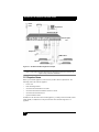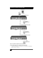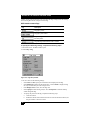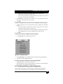
1
SERVSELECTTM FAMILY
Welcome to the ServSelect™ Family!
Thank you for purchasing a BLACK BOX® ServSelect product! We appreciate your
business, and we think you’ll appreciate the many ways that your new ServSelect will save
you money, time and effort.
That’s because the ServSelect family is all about breaking away from the traditional,
expensive model of computer management. You know, the one-size-fits-all-even-if-itdoesn’t model that says, “One computer gets one user station, no more, no less.” Why not a
single user station (monitor, keyboard, and mouse) for multiple computers—even computers
of different platforms? Why not a pair of user stations, each of which can control multiple
computers? Why not multiple user stations for the same computer?
With our ServSelect products, there’s no reason why not. We carry a broad line of robust
solutions for all these applications. Do you have just two PCs, and need an economical
alternative to keeping two monitors, keyboards, and mice on your desk? Or do you need to
share dozens of computers, including a mix of IBM® PC, RS/6000®, Apple®
Macintosh®, Sun Microsystems®, and SGI™ compatibles among multiple users with
different access levels? Does your switch have to sit solidly on a work table and use
regular everyday cables? Or does it have to be mounted in an equipment rack and use
convenient many-to-one cables? No matter how large or small your setup is, no matter
how simple or how complex, we’re confident we have a ServSelect system that’s just right
for you.
The ServSelect™ family from BLACK BOX—the one-stop answer for all your KVM
switching needs!
*
This manual will tell you all about your new ServSelect IP VM, including how to install,
operate, and troubleshoot it. For an introduction to the ServSelect IP VM, see Chapter 2.
The ServSelect product codes covered in this manual are:
KV2116A KV2116E KV4116A KV4116E
This manual also includes information about the ServSelect software and the Server
Access Modules (SAM), which have their own manuals or installation guides.
KV124A-PS2 KV124A-USB
1
SERVSELECT IP VM INSTALLER/USER GUIDE
FEDERAL COMMUNICATIONS COMMISSION
AND INDUSTRY CANADA
RADIO-FREQUENCY INTERFERENCE STATEMENTS
This equipment generates, uses, and can radiate radio-frequency energy and if not
installed and used properly, that is, in strict accordance with the manufacturer’s
instructions, may cause interference to radio communication. It has been tested and found
to comply with the limits for a Class A computing device in accordance with the
specifications in Subpart B of Part 15 of FCC rules, which are designed to provide
reasonable protection against such interference when the equipment is operated in a
commercial environment. Operation of this equipment in a residential area is likely to
cause interference, in which case the user at his own expense will be required to take
whatever measures may be necessary to correct the interference.
Changes or modifications not expressly approved by the party responsible for compliance
could void the user’s authority to operate the equipment.
This digital apparatus does not exceed the Class A limits for radio noise emission from
digital apparatus set out in the Radio Interference Regulation of Industry Canada.
Le présent appareil numérique n’émet pas de bruits radioélectriques dépassant les limites
applicables aux appareils numériques de la classe A prescrites dans le Règlement sur le
brouillage radioélectrique publié par Industrie Canada.
EUROPEAN UNION DECLARATION OF CONFORMITY
This equipment has been tested and found to comply with the limits for a Class A
computing device in accordance with the specifications in the European standard
EN55022. These limits are designed to provide reasonable protection against harmful
interference. This equipment generates, uses and can radiate radio-frequency energy, and
if not installed and used in accordance with the instructions, might cause harmful
interference to radio or television reception.
However, there is no guarantee that harmful interference will not occur in a particular
installation. If this equipment does cause interference to radio or television reception,
which can be determined by turning the equipment on and off, you can correct the
interference with one or more of the following measures:
a. Reorient or relocate the receiving antenna.
b. Increase the separation between the equipment and the receiver.
c. Connect the equipment to an outlet on a circuit different from that to which the receiver
is connected.
d. Consult the supplier or an experienced radio/TV technician for help.
2
COMPLIANCE STATEMENTS
Shielded cables must be used with this equipment to maintain compliance with radio
frequency energy emission regulations and ensure a suitably high level of immunity to
electromagnetic disturbances. This equipment has also been found to comply with
European standards EN50082 and EN60950.
Japanese Compliance Statement
Other Agency Approvals
USA (UL, FCC)
Canada (cUL, ICES-003)
European Union (CE)
TRADEMARKS USED IN THIS MANUAL
BLACK BOX® and the logo are registered trademarks, and ServSelect IP, ServSelect,
and ServSelect IP VM are trademarks of BLACK BOX Corporation.
Apple, Mac, and Macintosh are registered trademarks of Apple Computer, Inc.
IBM, PS/2, and RS/6000 are registered trademarks of International Business
Machines Corporation.
Microsoft, HyperTerminal, Windows, Windows NT, and Windows XP are trademarks or
registered trademarks of Microsoft Corporation in the United States and/or other countries.
Sun and Sun Microsystems are registered trademarks of Sun Microsystems, Inc. in the
United States and other countries.
UL is a registered trademark of Underwriters Laboratories Inc.
Any other trademarks mentioned in this manual are acknowledged to be the property of
the trademark owners.
3
SERVSELECT IP VM INSTALLER/USER GUIDE
Table of Contents
1. Product Specification ......................................................................................5
2. Product overview .............................................................................................7
2.1 Glossary .........................................................................................................................7
2.2 Features and benefits .....................................................................................................7
3. Installation ......................................................................................................11
3.1 Installation overview....................................................................................................11
3.2 Required items .............................................................................................................12
3.3 Safety Precautions........................................................................................................13
3.4 Connecting the appliance hardware .............................................................................13
3.5 Verifying Ethernet connections ...................................................................................15
3.6 Tiering multiple appliances .........................................................................................15
3.7 Configuring ServSelect IP VM Software ....................................................................17
3.8 Adjusting mouse settings .............................................................................................17
3.9 Adding earlier-model appliances .................................................................................17
3.10 Setting up the appliance .............................................................................................19
4. Basic operations ............................................................................................20
4.1 Controlling the switching system from the analog port...............................................20
4.2 Starting the OSD interface ...........................................................................................20
4.3 Connecting a user to a target device ............................................................................21
4.4 Using the OSD interface ..............................................................................................22
4.5 Connecting local virtual media ....................................................................................23
4.6 Configuring the appliance and the OSD interface .......................................................24
4.7 Setting the preemption warning ...................................................................................33
4.8 Managing target device tasks using the OSD interface ...............................................34
4.9 Scanning the switching system ....................................................................................38
4.10 Running switching system diagnostics ......................................................................39
4.11 Broadcasting to target devices ...................................................................................41
5. Computer terminal operations......................................................................43
5.1 The Console menu .......................................................................................................43
Appendix A: Flash upgrades ............................................................................45
Appendix B: Virtual media ................................................................................47
Appendix C: UTP cabling ..................................................................................49
Appendix D: Getting help and technical assistance.......................................51
4
CHAPTER 1: PRODUCT SPECIFICATION
1. Product Specification
Table 0.1: ServSelect IP VM appliance product specifications
Target Device Ports
Number
16
Connectors
RJ45
Sync Types
Separate horizontal and vertical
Supported Cabling
4-pair UTP Cat5 or Cat6, 10 meters maximum length
Video Resolution
640 x 480 @ 60 Hz
1280 x 1024 @ 75 Hz (Remote Port Maximum using a VM
SAM)
Serial Port
Number
1
Cable type
Serial RS-232
Connector
DB9 female RJ4 with RJ45 to DB-9 (female) adaptor
Network Connection
Number
1
Type
Ethernet: IEEE 802.3 2002 Edition - 10BASE-T, 100BASET, 1000BASE-T
Connector
RJ45
Local Port
Number
1
Type
USB, PS/2, and VGA
Connectors
PS/2 miniDIN, 15 pin D, RJ45, USB Type A
USB Device Port
Number
4
Type
USB 2.0
Dimensions
Height x Width x
Depth
1.72 in. x 17.00 in.x 11 in.; 1-U form factor
(4.37 cm x 43.18 cm x 28 cm)1.10 x 8.08 x 6.30 in
(2.80 x 20.51 x 16.00 cm)
Weight
7.3 lbs (3.31 kg)5.3 lbs (2.40 kg)1.1 lbs (0.50 kg) without
cables
5
SERVSELECT IP VM INSTALLER/USER GUIDE
Table 0.1: ServSelect IP VM appliance product specifications (Continued)
Heat Dissipation
105 BTU/hr
Airflow
8 cfm
Power consumption
30 Watts
AC-input power
40 Watts maximum
AC-input voltage rate
100 to 240 V AC Autosensing
AC-input current
rating
0.5 A RMS Max
AC-input cable
18 AWG three-wire cable, with a three-lead IEC-320
receptacle and a country-dependent connector on the
power resource end
AC frequency
50 to 60 Hz autosensing
Ambient atmospheric condition ratings
Temperature
Humidity
0o to 50o Celsius (32o to 122o Farenheit) operating
-40o to 70o Celsius (-40o to 158o Farenheit) nonoperating
20 to 80% noncondensing operating
5 to 95% noncondensing nonoperating
Safety and EMC approvals and markings
UL, FCC class A, cUL, ICES-03 emissions, CE, VCCI
Class A,
User Consoles
Type
6
PC running Windows NT, 2000 or XP OS and ServSelect
console application
Minimum Configuration-300MHz Pentium III,
64 MB RAM, 100BaseT NIC, XGA Video
Recommended Configuration-450 MHz Pentium III,
128 MB RAM, 100BaseT NIC, SXGA Video
CHAPTER 2: PRODUCT OVERVIEW
2. Product overview
The Black Box® ServSelect IP VM appliance integrates analog and digital keyboard,
video, and mouse (KVM) switching technology with advanced cable management, access
for two or four simultaneous users, and a user interface. The appliance has USB and PS/2®
ports on the rear panel that support all major target device platforms.
2.1 Glossary
The following words are used throughout this documentation:
•
appliance - equipment that provides KVM connectivity to attached target devices
•
SAM - a Server Access Module that, when attached to the appliance and a target
device, provides additional functionality such as virtual media sessions
•
switching system - a set of appliances and attached target devices and SAMs
•
target device - equipment such as a server or router that is attached to an appliance
•
user - a KVM connection from a port on the appliance
•
virtual media - a feature to allow a USB media device to be attached to the appliance
and made available to any target device that is connected to the appliance
2.2 Features and benefits
•
The ServSelect IP VM is a rack mountable KVM switch configurable for digital
(remote) connectivity. It features High-Speed Rack Interface (AHI) ports for
connecting servers and serial devices via SAM modules.
•
Supports Universal Serial Bus (USB) virtual media.
•
Video resolutions are supported up to 1280 x 1024 for remote users.
The ServSelect IP VM appliance includes up to four digital port sets for KVM-over-IP
access, 16 target device interface ports for connecting SAMs and target devices, and
virtual media capability for one local user and up to four remote users.
The ServSelect IP VM switch has user peripheral ports for PS/2 keyboards and mice.
Additionally, virtual media such as generic removable media and CD drives can be
connected to any one of four USB ports.
The appliance works over standard LAN connections. Users can access target devices
across a 1000BASE-T LAN port that is used to establish an Ethernet connection, or
directly through a local port. Users can access target devices across a 100BaseT LAN port
that is used to establish an Ethernet connection, or directly through a local port.
The IP-based appliance gives you target device control from anywhere in the world.
Intelligent cables
You can use the following Server Access Modules (SAMs) with the appliance.
•
PS2M SAM - PS/2 and VGA connectors
•
VM SAM - USB2 and VGA connectors
NOTE:
PS2M SAM and VM SAM are required for virtual media connections.
•
SERIAL SAM - Serial connectors
7
SERVSELECT IP VM INSTALLER/USER GUIDE
•
•
PS/2 SAM - PS/2 connectors without virtual media capability
USB SAM - USB connectors without virtual media capability.
PS2M SAM
VM SAM
Figure 2-1. Examples of SAMs
These intelligent SAMs with Cat5 design dramatically reduce cable clutter while
providing optimal digital display resolution and video settings. The built-in memory of the
SAM simplifies configuration by assigning and retaining unique target device
identification codes for each attached target device. This integrated intelligence enhances
security and prevents unauthorized access to a target device through cable manipulation.
The SAM is powered directly from the target device and proides Keep Alive functionality
when the appliance is not turned on.
The SAMs enable direct KVM connectivity to target devices that are attached to the
appliance. Each appliance has 16 target device interface ports for connecting SAMs.
The SAMs that work with the appliance support target devices with PS/2 and USB
ports. When using the On Screen Display (OSD) interface in conjunction with SAMs,
you can easily switch between platforms.
Virtual Media
The appliance supports virtual media when connected to a VM SAM. You can use virtual
media support to connect USB media devices to the appliance and a USB media device
that can be attached to the appliance and made available to any target device that is
connected to the appliance with a VM SAM. Use virtual media to move data between a
target device and USB media devices that are connected to the appliance. You can install,
upgrade, or recover the operating system; update the BIOS code; or start the target device
from a USB drive through the virtual media capabilities of the appliance.
Virtual media can be connected directly to the appliance using one of four USB ports on
the appliance. In addition, virtual media can be connected to any remote workstation that
is running ServSelect IP VM Software and is connected to the appliance using an Ethernet
connection. To open a virtual media session with a target device, the target device must
first be connected to the appliance using a VM SAM.
OSD graphical user interface
The appliance uses the OSD interface, which has menus to configure the switching system
and select computers. You can list target devices by unique name, eID (electronic ID), or
port number.
8
CHAPTER 2: PRODUCT OVERVIEW
Security
Use the OSD interface to protect the switching system with a screen saver password. After
a user-defined time, the screen saver mode engages and access is prohibited until the
correct password is entered to reactivate the switching system.
Operation modes
The OSD user interface provides various operation modes for system administration of the
appliance. Use these modes (Broadcast, Scan, Switch, and Share) to manage the switching
activities. See Chapter 4, “Basic operations”, beginning on page 20 for more information.
Video
The appliance provides optimal resolution for VGA, SVGA, and XGA video. You can
achieve resolutions of up to 1280 x 1024.
Flash upgradability
Upgrade the appliance at any time through the network port to ensure the appliance is
always running the most current available version. See “Appendix A” beginning on
page 45 for more information.
Accessing the appliance through network connection
Users access the appliance and all attached target devices through Ethernet from a client
computer. A client computer can be anywhere a valid network connection exists.
Accessing target devices
When you access the ServSelect IP VM Software, a listing of all target devices you have
permission to view and manage opens. When you select a target device from the list, the
video of the selected target device opens in a Video Viewer window.
The following figure illustrates a typical appliance configuration.
9
SERVSELECT IP VM INSTALLER/USER GUIDE
Rack of
target devices
ServSelect IP VM appliance
Virtual media
device
Ethernet
Digital user
Local user
Digital user
Figure 2-2. Example ServSelect IP VM appliance configuration
NOTE: To have server access to USB media device, utilize the LAN connection via the
VM SAM path.
10
CHAPTER 3: INSTALLATION
3. Installation
The appliance requires connectivity to a computer running ServSelect IP VM Software.
Use ServSelect IP VM Software to view and control target devices (one at a time) attached
to the appliance. The analog port does not require the ServSelect IP VM Software for
operation. The analog port uses the OSD graphical user interface. For more information
see the ServSelect IP VM Software Installation and User’s Guide.
The appliance transmits KVM information between operators and target devices attached
to the appliance over a network using either an Ethernet or local connection.
The appliance uses TCP/IP for communication over Ethernet. Although 10BASE-T
Ethernet can be used, using a dedicated, switched 100BASE-T network or a 1000BASE-T
network will improve performance.
3.1 Installation overview
To set up and install the appliance, complete the following steps:
1. Unpack the appliance and verify that all components are present and in good condition. See “Required items” on page 12.
2. Make all hardware connections between the power source, appliance, target devices,
and the Ethernet. Make all hardware connections between the power source, switch,
target device and the Ethernet. See “Safety precautions” on page 12.
3. Turn on the power and verify that all connections are working. See “Verifying Ethernet connections” on page 15.
4. To configure the appliance, complete one of the following steps:
•
You can use the console menu interface to configure the appliance. See Chapter
5, “Computer terminal operations”, beginning on page 43.
•
You can use the ServSelect IP VM Software to configure the appliance. See the
ServSelect IP VM Software Installation and User’s Guide for detailed instructions.
5. Make the needed mouse setting adjustments. See “Adjusting mouse settings” on
page 17.
6. Configure the OSD, which enables you to view and control the target devices, all
from the local port.
Setting up the network
The appliance and SAMs use IP addresses to uniquely identify the appliance and the target
devices. The appliance supports both Dynamic Host Configuration Protocol (DHCP) and
static IP addressing. To avoid confusion, have IP addresses that are reserved for each
appliance and remain static while the appliance is connected to the network. For additional
information on setting up the appliance using the ServSelect IP VM Software, and for
information on how the appliance uses TCP/IP, see the ServSelect IP VM Software
Installation and User’s Guide.
11
SERVSELECT IP VM INSTALLER/USER GUIDE
Power
Cord
Ethernet
Digital User
ServSelect IP VM
Interface ports
1-16
Peripherals
SAM module
Servers
Figure 3-1. ServSelect IP VM configuration example
NOTE:
To open a virtual media session with a target device, the target device must first be connected to the
appliance using a VM SAM or PS2M SAM.
3.2 Required items
Before you install the appliance, make sure that you have all the required items. The
following items come with the appliance:
•
Power cord
•
Rack-mounting brackets
•
ServSelect IP VM Installer/User Guide
•
ServSelect IP Software Installation and User’s Guide
•
ServSelect IP VM Software CD
•
Quick Installation Guide
In addition to the items that come with the appliance, you must provide one SAM (virtual
media, KVM, or USB) and one Cat5 patch cable for each attached target device or
appliance.
12
CHAPTER 3: INSTALLATION
3.3 Safety Precautions
To avoid potential video and/or keyboard problems when using Black Box
products:
•
If the building has 3-phase AC power, ensure that the computer and monitor are
on the same phase. For best results, they should be on the same circuit.
To avoid potentially fatal shock hazard and possible damage to equipment,
please observe the following precautions:
•
Do not use a 2-wire power cord in any Avocent product configuration.
•
Test AC outlets at the target device and monitor for proper polarity and
grounding.
•
Use only with grounded outlets at both the target device and monitor. When
using a backup Uninterruptible Power Supply (UPS), power the target device, the
monitor and the switch from the UPS.
NOTE: The AC inlet is the main power disconnect.
Rack mount safety considerations
Elevated Ambient Temperature: If installed in a closed rack assembly, the operating
temperature of the rack environment may be greater than room ambient. Use care not to
exceed the rated maximum ambient temperature of the switch.
Reduced Air Flow: Installation of the equipment in a rack should be such that the amount
of airflow required for safe operation of the equipment is not compromised.
Mechanical Loading: Mounting of the equipment in the rack should be such that a
hazardous condition is not achieved due to uneven mechanical loading.
Circuit Overloading: Consideration should be given to the connection of the equipment
to the supply circuit and the effect that overloading of circuits might have on overcurrent
protection and supply wiring. Consider equipment nameplate ratings for maximum
current. Consideration should be given to the connection of the equipment to the supply
circuit and the effect that overloading of circuits might have on overcurrent protection and
supply wiring. Consider equipment nameplate ratings for maximum current.
Reliable Earthing: Reliable earthing of rack mounted equipment should be maintained.
Pay particular attention to supply connections other than direct connections to the branch
circuit (for example, use of power strips). Reliable earthing of equipment should be
maintained. Pay particular attention to supply connections other than direct connections to
the branch circuit (for example, use of power strips).
3.4 Connecting the appliance hardware
To connect and turn on the appliance, complete the following steps:
1.
2.
Turn off the target devices that are part of the switching system. Connect one end of
the power cord to the rear of the appliance and connect the other end to an AC power
source.
Connect a VGA monitor and either PS/2 or USB keyboard and mouse cables into the
labeled appliance ports. You must install both a keyboard and mouse on the local
13
SERVSELECT IP VM INSTALLER/USER GUIDE
3.
4.
5.
6.
7.
8.
ports or the keyboard will not initialize correctly. You cannot connect a DVI or EGA
monitor to the appliance.
Connect one end of a Cat5 patch cable (4-pair, up to 10 meters) into a target device
interface port and connect the other end into the RJ45 connector of a SAM. Plug one
end of a Cat 5 patch cable (4-pair, up to 10 meters) into the SAM port and plug the
other end into the RJ45 connector of a SAM module.
Connect the SAM into the correct ports on the rear of the target device. Repeat this
procedure for all target devices that are to be connected to the appliance.
Connect a Cat5 patch cable from the Ethernet network into the LAN port on the rear
of the appliance. Network users will access the appliance through this port.
If you are configuring the appliance using the console menu interface, connect a
computer running terminal emulation software to the SETUP port on the rear panel of
the appliance using a straight serial cable. If you will be configuring the switch using
the console menu interface, connect a terminal or PC running terminal emulation
software to the SETUP port on the back panel of the switch using the supplied cable.
The terminal should be set to 9600 bits per second (bps), 8 bits, 1 stop bit, no parity,
and no flow control. Otherwise, proceed to the next step.
Turn on each target device and then turn on the appliance. Power up the target device
and then power up the appliance. After approximately one minute, the appliance
completes initialization and opens the OSD graphical user interface Free tag on the
local port monitor. After approximately one minute, the switch completes initialization and displays the target video on the local port monitor.
Use the ServSelect IP VM Software to configure the appliance. See the ServSelect IP
VM Software Installation and User’s Guide for detailed instructions.
Connecting a SAM to each target device
To connect a SAM to a target device, complete the following steps:
1.
2.
3.
4.
Attach the color-coded connectors of the SAM to the keyboard, monitor, and mouse
ports on the first target device that you connect to the appliance.
Attach one end of the Cat5 cable to the RJ45 connector on the SAM.
Connect the other end of the Cat5 cable to a target device interface port on the rear of
the appliance.
Repeat steps 1 to 3 for all target devices that you are attaching.
Connecting local peripheral devices
To connect local peripheral devices to the appliances, complete the following steps:
1. Connect a keyboard, monitor, and mouse to each set of color-coded ports on the rear
of the appliance.
2. Bundle and label the cables for easy identification.
To connect local virtual media, complete the following step:
Connect the virtual media to any one of the four USB ports on the appliance. For all
virtual media sessions, you must use a VM SAM.
14
CHAPTER 3: INSTALLATION
3.5 Verifying Ethernet connections
The Ethernet connection has two LEDs. The green LED on the right is the Link indicator.
It is lit when a valid connection to the network is established and it flashes when there is
activity on the port. The amber/green LED on the left indicates that you are
communicating at 100 Mbps (amber) or 1000 Mbps (green) when using the Ethernet
connection.
3.6 Tiering multiple appliances
You can tier multiple appliances to enable up to four users to connect to up to 4096 target
devices. For usability reasons, make sure that the ServSelect IP VM appliance is the top
tier. The ServSelect IP VM appliance is not designed to be part of the second tier.
15
SERVSELECT IP VM INSTALLER/USER GUIDE
Local user A
ServSelect IP VM appliance
Primary
target devices
ServSelect III VM appliance (tiered)
ACI port
Secondary
target devices
ServSelect III VM appliance (tiered)
ACI port
Tertiary
target devices
Figure 3-2. Appliance configuration with a tiered appliance
To tier multiple appliances, complete the following steps:
1.
16
Connect the tiered appliance to each target device as described in “Connecting the
appliance hardware” on page 13.
CHAPTER 3: INSTALLATION
2.
3.
4.
5.
Connect the peripheral devices to the local user port on the main appliance. See
“Connecting local peripheral devices” on page 14.
If the secondary appliance is a ServSelect III VM or ServSelect III, attach one end of
the Cat5 cable to the ACI port on the tiered appliance.
Attach the other end of the Cat5 cable to one of the target device interface ports on
the rear of the main appliance.
The switching system will automatically merge the two appliances. All target devices
that are connected to the tiered appliance are included in the main appliance target
device list in the OSD interface. However, if you are tiering an earlier-model appliance, the list of appliances in the OSD interface will display both the primary appliance port number and the secondary or tertiary appliance port number. See “Adding
earlier-model appliances” for more information.
Repeat steps 3 and 4 for all additional tiered appliances you want to attach.
3.7 Configuring ServSelect IP VM Software
See the ServSelect IP VM Software Installation and User’s Guide included on the CD with
the software.
3.8 Adjusting mouse settings
Before a computer connected to the appliance can be used for remote user control, you
must set the target mouse speed and turn off acceleration.
If you are experiencing slow mouse response during a remote video session, deactivate
mouse acceleration in the operating system of the target device and set the mouse speed at
50%.
3.9 Adding earlier-model appliances
You can add earlier-model appliances for integration into the existing configuration. In a
tiered system, each target device interface port will accommodate up to 16 target devices.
When earlier-model appliances are tiered under the ServSelect IP VM appliance, the
ServSelect IP VM appliance must be at the top level of the tier.
17
SERVSELECT IP VM INSTALLER/USER GUIDE
Local user
ServSelect IP VM
Tiered appliance
Figure 3-3. Appliance configuration with an earlier-model appliance
To attach an earlier-model appliance to the ServSelect IP VM appliance,
complete the following steps:
1.
2.
18
Mount the earlier-model appliance into the rack according to the instructions that are
included with that device.
Either attach the keyboard, monitor, and mouse connectors of a SAM to the local port
on the tiered appliance and attach one end of a Cat5 cable to the end of the SAM, or
attach one end of a Cat5 cable directly to the ACI port on the tiered appliance.
CHAPTER 3: INSTALLATION
3.
Connect the other end of the Cat5 cable to one of the target device interface ports on
the rear of the appliance.
4. Turn off and turn on the target devices to the tiered appliance according to the
instructions that are included with that device.
5. Turn off and turn on the tiered appliance to enable its local port to recognize the
SAM.
6. Repeat steps 1 to 5 for all tiered appliances that you want to attach to the switching
system.
The switching system will automatically merge the two appliances. All target devices that
are connected to the tiered appliance are included in the main appliance target device list
in the OSD interface. However, when an earlier-model appliance is connected to a PS2M
SAM, the list of appliances in the OSD interface will display both the primary appliance
port number, followed by a dash, and the secondary appliance port number. For example,
the Port column for a secondary earlier-model appliance might display 01-02, where 01 is
the primary port and 02 is the secondary port.
3.10 Setting up the appliance
With the appliance, you can auto detect and configure each port on the appliance. Chapter
4 provides detailed instructions on naming customization and OSD interface setup
and configuration.
19
SERVSELECT IP VM INSTALLER/USER GUIDE
4. Basic operations
4.1 Controlling the switching system from the analog
port
The appliance includes ports on the rear panel that you can use to connect a keyboard,
monitor, and mouse to the appliance for direct analog access. The appliance uses the OSD
interface, which has intuitive menus to configure the switching system and select target
devices. Devices can be identified by customizable names.
4.2 Starting the OSD interface
You can view, configure, and control target devices in the switching system from the OSD
interface from a KVM connection to the analog port.
To start the OSD interface, press Print Screen. Alternatively, you can press the Control,
Alt, or Shift key twice within 1 second to start the OSD interface. You can use any of these
key sequences instead of pressing Print Screen in any procedure in this document. To
specify which key sequences can be used to start the OSD interface, click Setup > Menu.
The following illustration is an example of the Main window of the OSD interface.
Figure 4-1. Example of a Main window
The Main window lists the target devices in the switching system. You can order the list
by target device names, eID numbers, or port numbers by clicking the Name, eID, or Port
button.
The Port column indicates the target device interface port to which each target device is
connected. If an earlier-model appliance is connected to a ServSelect IP VM appliance,
the target device interface port number is shown first, followed by the number of the
appliance port to which the target device is connected. For example, in Figure 3.1, the
target device named Acton is connected to target device interface port 06 and appliance
port 01.
20
CHAPTER 4: BASIC OPERATIONS
The status of each target device in the switching system is indicated by one or more status
symbols in the right column. The following table describes the status symbols.
OSD interface status symbols
Symbol
Description
The SAM is online (green circle).
The SAM is offline or is not operating correctly.
The target device is tiered through another appliance. The
target device and the appliance are online and have power.
The target device is tiered through another appliance. The
appliance is offline or does not have power.
The SAM is being upgraded (yellow circle). When this symbol is
visible, do not turn off and turn on the appliance or connected
target devices and do not disconnect the SAM. Doing so might
damage the SAM permanently.
The SAM is being accessed by the indicated user channel
(green channel letter).
The SAM is blocked by the indicated user channel (black
channel letter). For instance, in Figure 4.1, user C is viewing
Forester, but is blocking access to Acton, Barrett, and Edie
which are connected to the same SAM.
A remote virtual media connection is established to the target
device connected to the indicated user channel (blue letter).
You can set a screen delay to specify the length of time that elapses between when Print
Screen is pressed and when the OSD interface starts. To set a screen delay, complete the
following steps:
1. Press Print Screen to start the OSD interface.
2. In the Main window, click Setup > Menu.
3. In the Screen Delay Time field, type the number of seconds that you want to elapse
between when Print Screen is pressed and when the OSD interface starts.
4.3 Connecting a user to a target device
Use the Main window of the OSD interface to select a target device to which you want to
connect. When you select a target device, the keyboard and mouse are automatically
reconfigured to the correct settings for that target device.
To select a target device, press Print Screen to start the OSD interface, and then use one of
the following procedures:
21
SERVSELECT IP VM INSTALLER/USER GUIDE
•
In the Main window, double-click the target device name, eID number, or port
number.
•
Type the port number, and press Enter.
•
Type the first few characters of the target device name or eID number, and press
Enter.
You can toggle between two selected target devices. To select the previously selected
target device, press Print Screen and press Backspace.
To disconnect the user from a target device, press Print Screen and press Alt+0. A Free
status flag in the OSD interface indicates that the user is not connected to a target device.
4.4 Using the OSD interface
This table describes the keys, key combinations, and mouse actions that you can use in the
OSD interface. Two or more key names or mouse actions that are separated by commas
indicate a sequence of actions. Two or more key names or mouse actions that are
separated by a plus sign (+) indicate a combination of actions; that is, they are performed
simultaneously.
You can use the main keyboard or the numeric keypad to type numerals, except when you
use the Alt+0 key combination; you must use the 0 key on the main keyboard when you
use Alt+0.
OSD interface navigation basics
Key, key combination, or
mouse action
Result
Print Screen; Ctrl, Ctrl; Shift,
Shift; or Alt, Alt
Start the OSD interface. To specify which key
sequences can be used to start the OSD interface,
click Setup > Menu.
Print Screen, Print Screen
Send the Print Screen keystroke to the currently
selected target device. In other words, a screen
capture will be performed for the target device.
If Print Screen is not selected as startup key
sequence in Setup > Menu, you only need to press
Print Screen once to take a screen capture of the
target device.
F1
Display help for the current window.
Escape
In the OSD main window: Close the OSD interface
and return to the status flag on the desktop.
In all other windows: Close the current window,
without saving changes, and return to the previous
window.
In pop-up windows: Close the pop-up window and
return to the current window.
Alt+X
Close the current window, without saving changes,
and return to the previous window.
Alt+O
Click OK and return to the previous window.
22
CHAPTER 4: BASIC OPERATIONS
OSD interface navigation basics (Continued)
Key, key combination, or
mouse action
Result
Alt+port number
Select a target device to be scanned; port number
is the port number of the target device.
Enter
Completes a switch in the Main window and exits
the OSD interface.
Click on an editable field to select the text for editing
and enable the Left and Right arrow keys to move
the cursor. Press Enter to quit the edit mode.
Print Screen, Backspace
Return to the previously selected target device.
Print Screen, Alt+0
Disconnect the user from the selected target
device. Note that the zero must be typed on the
main keyboard, not the numeric keypad.
Print Screen, Pause
Start the screen saver immediately and lock the
user, if it is password-protected.
Up Arrow or Down Arrow
Move the cursor from line to line in a list.
Right Arrow or Left Arrow
When editing text in a field: Move within the text in
the field.
All other conditions: Move the cursor from column
to column in a list.
Page Up or Page Down
Page through a list or help window.
Home or End
Move the cursor to the top or bottom of a list.
Delete
Delete the selected characters in a field or the
selected item in the scan list. For more information
about scan lists see “Scanning the switching
system” on page 38.
4.5 Connecting local virtual media
You can connect virtual media directly to the appliance using the USB port on the
appliance.
Note that all USB ports are assigned to a single virtual media session and cannot be
independently mapped.
To start a local virtual media session, complete the following steps:
1.
2.
3.
4.
5.
Press Print Screen to start the OSD interface. The Main window opens.
Connect the user to the target device with which you want to establish a virtual media
session. Use the arrow keys to highlight the target device name, and then press Enter.
Press Print Screen to start the OSD interface again.
Click the VMedia button. The Virtual Media window opens.
Select one or more of the following check boxes:
23
SERVSELECT IP VM INSTALLER/USER GUIDE
•
6.
Locked - Select this check box to specify that when the user is disconnected
from a target device, the virtual media is also disconnected.
•
Reserve - Select this check box to specify that the virtual media connection can
be accessed only by your user name and that no other user can connect to that
target device. If both Locked and Reserved are selected, the session will be
reserved.
•
CD ROM - Select this check box to establish a virtual media CD connection to
a target device. Clear this check box to end the connection.
•
Mass Storage - Select this check box to establish a virtual media mass-storage
connection to a target device. Clear this check box to end the connection.
•
Write Access - Select this check box to enable the connected target device to
write data to the virtual media during a virtual media session. Read access is
always enabled during virtual media sessions.
Click OK.
4.6 Configuring the appliance and the OSD interface
To configure the appliance and the OSD interface, start the OSD interface and click
Setup. The following illustration shows the Setup window.
Figure 4-2. Setup window
The following table describes the options in the Setup window.
Setup features to manage routine tasks for the target devices
Option
Purpose
Menu
Order the list of target devices by target device name, eID number,
or port number. Set a screen delay to specify the length of time that
elapses between when Print Screen is pressed and when the OSD
interface starts.
24
CHAPTER 4: BASIC OPERATIONS
Setup features to manage routine tasks for the target devices
Option
Purpose
Security
Set passwords to restrict access to the target devices. Enable the
screen saver.
Flag
Change the display properties including timing, color, and location of
the status flag.
Language
Specify the language that the interface is displayed in.
Devices
Specify the number of ports that are on the attached tiered
appliance.
Names
Assign a unique name to each target device.
Keyboard
Specify the keyboard country code.
Broadcast
Simultaneously control multiple target devices through keyboard
and mouse actions.
Scan
Set up a custom scan pattern for up to 16 target devices.
Preempt
Specify preemption settings.
Network
Specify the network speed and configuration, IP address, netmask,
and gateway for the switching system.
Assigning target device names
Use the Names window to identify individual target devices by name rather than by port
number. The Names list is always sorted by port order. Names are stored in the SAM, so
even if you move the cable or target device to another target device interface port, the
name and configuration are recognized by the appliance. If a target device is turned off,
you cannot modify the name of the SAM.
To access the Names window, complete the following steps:
1.
2.
Press Print Screen to start the OSD interface. The Main window opens.
Click Setup > Names. The Names window opens.
25
SERVSELECT IP VM INSTALLER/USER GUIDE
Figure 4-3. Names window
If new SAMs are discovered by the appliance, the on-screen list will be automatically
updated. The mouse cursor will change into an hourglass during the update. No mouse or
keyboard input will be accepted until the list update is complete.
To assign names to target devices, complete the following steps:
1.
In the Names window, select a target device name or port number and click Modify.
The Name Modify window opens.
Figure 4-4. Name Modify window
2.
Type a name in the New Name field. Names of target devices can be up to 15 characters
long. Valid characters are A through Z, a through z, 0 through 9, space, and hyphen.
3. Click OK to transfer the new name to the Names window. The selection is not saved
until you click OK in the Names window.
4. Repeat steps 1 to 3 for each target device in the switching system.
5. Click OK in the Names window to save the changes, or click X or press Escape to
exit without saving changes.
If a SAM has not been assigned a name, the eID is used as the default name. To list target
devices alphabetically by name, press Alt+N or click Name in the Main window.
26
CHAPTER 4: BASIC OPERATIONS
Assigning device types
The ServSelect IP VM appliance automatically discovers attached tiered appliances, but
you must specify the number of ports on the tiered appliance through the Devices window.
Black Box Console Switches and other earlier-model appliances are listed in the Type
category for the tiered appliance. When you select a configurable appliance from the list,
the Modify button becomes available, so you can assign it the correct number of ports.
To access the Devices window, complete the following steps:
1.
2.
Press Print Screen to start the OSD interface. The Main window opens.
Click Setup > Devices. The Devices window opens.
Figure 4-5. Devices window
When the appliance discovers a tiered appliance, the port numbering changes to
accommodate each target device under that appliance.
For example, if the appliance is connected to target device interface port 6, the appliance
port is listed as 06, and the target devices that are under it are numbered sequentially as
06-01, 06-02, and so on.
To assign a device type, complete the following steps:
1.
2.
In the Devices window, select the port number.
Click Modify. The Device Modify window opens.
27
SERVSELECT IP VM INSTALLER/USER GUIDE
Figure 4-6. Device Modify window
3.
4.
5.
Select or type the number of ports that are supported by the tiered appliance and click
OK.
Repeat steps 1 to 3 for each port for which you want to assign a device type.
Click OK in the Devices window to save settings.
Changing the display behavior
Use the Menu window to change the order of the target devices and set a screen delay for
the OSD interface. The display order setting affects the order in which target devices are
listed in several windows, including the Main, Devices, and Broadcast windows.
To access the Menu window, complete the following steps:
1.
2.
Press Print Screen to start the OSD interface. The Main window opens.
Click Setup > Menu. The Menu window opens.
Figure 4-7. Menu window
To select the order of the target devices, complete the following steps:
1.
28
Click one of the following buttons:
CHAPTER 4: BASIC OPERATIONS
•
Select Name to list the target devices alphabetically by target device name.
•
Select eID to list the target devices numerically by eID number.
•
Select Port to list the target devices numerically by port number.
Click OK.
To select a key combination to start the OSD interface, complete the
following steps:
1.
In the Invoke OSD section, select which key combinations you want to use to start
the OSD interface, then press your selected combination.
2. Click OK.
You can set a screen delay so that you can select a target device using the keyboard
without starting the OSD interface. A screen delay specifies the length of time that elapses
between when Print Screen is pressed and when the OSD interface starts. To set a screen
delay, complete the following steps:
1. Type the number of seconds (0 through 9) to specify the length of time that elapses
between when Print Screen is pressed and when the OSD interface starts. If you specify 0, there is no delay.
2. Click OK.
Selecting display language
Use the Setup window to change the display language for the OSD interface.
Figure 4-8. Language window
To select a language for the OSD interface:
1.
2.
3.
Press Print Screen to start the OSD interface. The Main window opens.
Click Setup > Language. The Language window opens.
In the Language window, select the language and click OK.
Controlling the status flag
The status flag is displayed on the desktop and indicates the name or eID number of the
selected target device or the status of the selected port. You can specify the information
that is displayed in the flag, the flag color, whether the desktop is visible through the flag,
29
SERVSELECT IP VM INSTALLER/USER GUIDE
whether the flag is displayed all the time, and where the flag is displayed on the desktop.
The following table shows examples of status flags.
OSD interface status flags
Flag
Description
Flag type by name.
Flag type by eID number.
Flag indicating that the user has been disconnected
from all systems.
Flag indicating that Broadcast mode is enabled.
To specify the status-flag settings, complete the following steps:
1. Press Print Screen. The Main window opens.
2. Click Setup > Flag.
Figure 4-9. Flag Setup window
3. Set one or more of the following settings:
•
Select Name or eID to specify the information that is displayed in the flag.
•
Select Displayed to display the flag all the time, or select Timed to display the flag
for only 5 seconds after you select a target device.
•
In the Display Color section, select the flag color.
•
Select Opaque to make the flag solid, or select Transparent to make the desktop
visible through the flag.
•
To specify the position of the flag, complete the following steps:
a. Click Set Position.
b. Hold down the left mouse button on the title bar of the Set Position window, and
drag the window to the new location.
30
CHAPTER 4: BASIC OPERATIONS
c.
Press the right mouse button to close the Set Position window.
Figure 4-10. Set Position window
4.
4. Click OK to save the changes, or click X or press Escape to exit without saving the
changes.
Setting the keyboard country code
By default, the appliance sends the US keyboard country code to USB cables attached to
target devices and the code is applied to the target devices when they are turned on or
rebooted. Codes are then stored in the SAM. Using a keyboard code that supports a
language different from that of the appliance firmware will cause incorrect keyboard
mapping.
If multiple keyboards are connected to the local port, they must be of the same type (PC or
Mac) and of the same language. Only local users can view or change keyboard country
code settings.
Issues might arise when you use the US keyboard country code with a keyboard of another
country. For example, the Z key on a US keyboard is in the same location as the Y key on
a German keyboard.
You can use the Keyboard window to send a different keyboard country code than the
default US setting.
Figure 4-11. Keyboard window
To change the keyboard country code, complete the following steps:
1.
2.
3.
Press Print Screen to start the OSD interface. The Main window opens.
Click Setup > Keyboard. The Keyboard window opens.
Select the country code for the keyboard, and click OK. Confirm the change in the
Keyboard Warning window.
31
SERVSELECT IP VM INSTALLER/USER GUIDE
4.
Click OK to save the change, or click X or press Escape to exit without saving the
change.
Setting appliance security
You can enable a screen saver to start if the user remains unused for a specified length of
time. When the screen saver starts, the user is disconnected from any target device to
which it was connected. The screen saver stops when you press any key or move the
mouse.
To immediately start the screen saver, press Print Screen and press Pause.
If you set a password, the keyboard and mouse are locked when the screen saver starts.
When you press a key or move the mouse while the screen saver is running, a Password
window opens, and you must type the password and click OK to unlock the keyboard and
mouse.
Important: If you forget the password, you must call technical support. See “Appendix
D” beginning on page 51 for contact information.
To enable the screen saver, complete the following steps:
1.
2.
3.
4.
5.
6.
7.
Press Print Screen. The Main window opens.
Click Setup > Security. If a password is set, the Password window opens. Type the
password and click OK.
Select the Enable Screen Saver check box.
In the Inactivity Time field, type the number of seconds (1 through 99) that must
elapse before the screen saver starts.
If the monitor is Energy Star compliant, select Energy; otherwise, select Screen.
(Optional) To run the screen-saver test, click Test. The screen-saver test runs for 10
seconds.
Click OK.
To disable the screen saver, complete the following steps:
1.
2.
Press Print Screen. The Main window opens.
Click Setup > Security. If a password is set, the Password window opens. Type the
password and click OK.
3. Clear the Enable Screen Saver check box.
4. Click OK.
A password must contain both alphabetic and numeric characters and can be up to 12
characters long. Passwords are case-sensitive. Valid characters are A through Z, a through
z, 0 through 9, space, and hyphen.
To set or change a password, complete the following steps:
1.
2.
3.
4.
5.
6.
32
Press Print Screen. The Main window opens.
Click Setup > Security. If a password is already set, the Password window opens.
Type the password and click OK.
Double-click the New field.
In the New field, type the new password.
In the Repeat field, type the password again.
Click OK.
CHAPTER 4: BASIC OPERATIONS
To disable password protection, complete the following steps:
1.
2.
3.
4.
5.
Press Print Screen. The Main window opens.
Click Setup > Security. In the Password window, type the password and click OK.
Double-click the New field. Leave the field blank, and press Enter.
Double-click the Repeat field. Leave the field blank, and press Enter.
Click OK.
4.7 Setting the preemption warning
Administrators and users with certain access rights can preempt (disconnect) KVM
sessions and take control of the target device. You can choose whether or not to warn the
first user that the session will be preempted and specify how long the appliance will wait
for the first user to respond to the warning.
For more information about preempting sessions and preemption settings, see the
ServSelect IP VM Software Installation and User’s Guide.
To view or change the preemption warning settings, complete the following
steps:
1.
2.
3.
4.
Press Print Screen. The Main window opens.
Click Setup > Preempt.
Enter a number of seconds in the Timeout Seconds field.
•
If you enter a value of 0 to 4 seconds, the first user will not be warned before the
session is preempted.
•
If you enter a value of 5 to 120 seconds, the first user will be warned and will be
allowed to continue using the target device for up to the amount of time in the
Timeout Seconds field. The session will be preempted when the user clicks
OK, or when the specified time elapses.
Click OK to save the settings.
Figure 4-12. Preempt window
33
SERVSELECT IP VM INSTALLER/USER GUIDE
4.8 Managing target device tasks using the OSD
interface
From the Commands window, you can manage the switching system and user
connections, enable the Scan and Broadcast modes, and update the firmware.
Commands to manage routine tasks for the target device
Feature
Purpose
SAM Status
View the version and upgrade status of the SAM.
Display Config View current display settings.
Run
Diagnostics
Configure and begin diagnostics on target devices.
Broadcast
Enable
Begin broadcasting to the target devices. Configure a target
device list for broadcasting under the Setup window.
Scan Enable
Begin scanning the target devices. Set up a target device list
for scanning in the Setup window.
User Status
View and disconnect users.
Display
Versions
View version information for the appliance as well as view and
upgrade firmware for individual SAMs.
Device Reset
Re-establish operation of the keyboard and mouse.
To access the Commands window, complete the following steps:
1.
2.
Press Print Screen. The Main window opens.
Click Commands. The Commands window opens.
Figure 4-13. Commands window
34
CHAPTER 4: BASIC OPERATIONS
Displaying version information
You can use the OSD interface to view the versions of the appliance and the SAM
firmware. For more information, see “Appendix A” beginning on page 45.
To view version information, complete the following steps:
1.
2.
Press Print Screen. The Main window opens.
Click Commands > Display Versions. The Version window opens. The top pane of
the window lists the subsystem versions in the appliance.
Figure 4-14. Version window
3.
4.
5.
Click the SAM button to view individual SAM version information. The SAM Select
window opens.
Select a SAM to view and click the Version button. The SAM Version window
opens. For more information about loading firmware, see “Appendix A” beginning
on page 45.
Click X to close the SAM Version window.
Upgrading the firmware
You can also use the OSD interface to upgrade the firmware available for the appliance.
For optimum performance, keep the firmware current.
35
SERVSELECT IP VM INSTALLER/USER GUIDE
Figure 4-15. Upgrade window
To upgrade firmware, complete the following steps:
1.
2.
3.
Press Print Screen. The Main window opens.
Click Commands > Display Versions > Upgrade. The Upgrade window opens.
Click Upgrade. A Warning window opens. Clicking OK opens the Upgrade Process
window. The progress of the upgrade is indicated in the Programmed field.
Viewing the display configuration
Use the Display Configuration window to view the current configuration of the switching
system.
To view the current configuration, click Commands > Display Config. The Display
Configuration window opens and lists the current system configuration values.
Viewing and disconnecting user connections
You can view and disconnect users from target devices through the User Status window.
The user (U) is always visible; however, you can display either the target device name or
eID number to which a user is connected. If there is no user currently connected to a
channel, the User and Server Name fields are blank.
36
CHAPTER 4: BASIC OPERATIONS
To view current user connections, click Commands > User Status. The User
Status window opens.
Figure 4-16. User Status window
To disconnect a user, complete the following steps:
1.
From the User Status window, click the letter that corresponds to the user to disconnect. The Disconnect window opens.
2. Complete one of the following steps:
•
Click OK to disconnect the user and return to the User Status window.
•
Click X or press Escape to exit the window without disconnecting a user.
If the User Status list has changed since it was last visible, the mouse cursor will turn into
an hourglass as the list is automatically updated. No mouse or keyboard input is accepted
until the list update is complete.
Figure 4-17. Disconnect window
Resetting the keyboard and mouse
You can reset the keyboard and mouse by clicking Commands > Device Reset. If the
keyboard or mouse is still not responding, you might be able to re-establish operation of
37
SERVSELECT IP VM INSTALLER/USER GUIDE
these peripheral devices by issuing a Reset command for the mouse and keyboard settings
on the target device. The Reset command sends a hot-plug sequence to the target device,
which causes the mouse and keyboard settings to be sent to the appliance. With
communication re-established between the target device and the appliance, functionality is
restored to the user. This function is for Microsoft Windows-based computers only.
Resetting the keyboard and mouse on a target device running any other operating system
might require that you reboot that target device.
To reset the mouse and keyboard values, complete the following steps:
1.
2.
3.
4.
5.
Press Print Screen. The Main window opens.
Click Commands > Display Versions > SAM. Select the SAM connected to the
mouse and keyboard that need to be reset from the list.
Click Version > Reset.
A message is displayed stating that the mouse and keyboard are reset.
Complete one of the following steps:
•
Click OK to close the message field.
•
Click X or press Escape to exit without sending a Reset command to the mouse
and keyboard.
4.9 Scanning the switching system
In scan mode, the appliance automatically scans from port to port (target device to target
device). Use scan mode to monitor the activity of up to 16 target devices, and to specify
which target devices to scan and the number of seconds that each target device will be
visible. The scanning order is determined by placement of the target device in the list,
which is always shown in scanning order. You can choose to list the target devices by
name, eID number, or port number by clicking the corresponding button.
To add target devices to the scan list, complete the following steps:
1.
Click Setup > Scan. The Scan window opens.
Figure 4-18. Scan window
2.
38
The window contains a listing of all target devices that are attached to the appliance.
To select target devices to be scanned, complete one of the following steps:
CHAPTER 4: BASIC OPERATIONS
•
•
•
3.
4.
Select the check box next to the target devices that you want to scan.
Double-click on a target device name or port.
Press Alt and the eID number of the target device that you want to scan. You can
select up to 16 target devices from the list.
In the Time field, type the number of seconds (from 3 to 255) of time before the scan
moves to the next target device in the sequence.
Click OK.
To remove a target device from the scan list, complete the following steps:
1.
2.
To select a target device to be removed from the scan list, complete one of the following steps:
•
In the Scan window, clear the check box next to the target device to be removed.
•
Double-click on the target device name or port.
•
Press Shift + Delete to remove the selected target device and all entries below it.
•
Click the Clear button to remove all target devices from the scan list.
Click OK.
To start the Scan mode, complete the following steps:
1.
Click Commands. The Commands window opens.
Figure 4-19. Commands window
2.
3.
Select Scan Enable in the Commands window. Scanning will begin immediately.
Click X to close the Commands window.
To cancel scan mode, complete one of the following steps:
•
•
If the OSD interface is open, select a target device.
If the OSD interface is not open, move the mouse or press any key on the keyboard to
stop scanning at the currently selected target device.
4.10 Running switching system diagnostics
You can validate the integrity of the switching system through the Run Diagnostics
command. This command checks the main board functional sub-systems (memory,
39
SERVSELECT IP VM INSTALLER/USER GUIDE
communications, appliance control, and the video channels) for each system controller.
When you select the Run Diagnostics button, a warning will indicate that all users
(remote and local) will be disconnected. Click OK to confirm and begin the test.
The Diagnostics window opens. The top section of the window opens the hardware tests.
The bottom portion divides the tested SAMs into three categories: On-line, Offline or
Suspect. SAMs might be listed as offline while being upgraded.
Figure 4-20. Diagnostics window
When the test is finished for an item, a pass (green circle) or fail (red x) symbol will be
visible to the left of the item. The following table details each of the tests.
Diagnostic test details
Test
Description
Firmware CRCs
Reports on the condition of the main board RAM.
Remote User
Video
Reports on the condition of the remote user video.
LAN Connection
Reports on the condition of the LAN connection.
On-line SAMs
Indicates the total number of currently connected and
turned on SAMs.
Offline SAMs
Indicates the number of SAMs that have been connected
successfully in the past and are turned off.
Suspect SAMs
Indicates the number of SAMs that have been detected, but
are either unavailable for connection or have dropped
packets during the ping tests.
To run diagnostic tests, complete the following steps:
1.
40
Click Commands > Run Diagnostics. A warning message indicates that all users
will be disconnected.
CHAPTER 4: BASIC OPERATIONS
2.
Click OK to begin diagnostics.
3.
4.
All users are disconnected and the Diagnostics window opens.
As each test is finished, a pass (green circle) or fail (red x) symbol is visible. The test
is complete when the last test symbol is visible.
4.11 Broadcasting to target devices
The analog user can simultaneously control more than one target device in a switching
system to ensure that all selected target devices receive identical input. You can choose to
independently broadcast keystrokes or mouse movements.
•
Broadcasting keystrokes - The keyboard state must be identical for all target
devices that are receiving a broadcast to identically interpret keystrokes. Specifically,
the Caps Lock and Num Lock modes must be the same on all keyboards. While the
appliance attempts to send keystrokes to the selected target devices simultaneously,
some target devices might inhibit and thereby delay the transmission.
•
Broadcasting mouse movements - For the mouse to work accurately, all systems
must have identical mouse drivers, desktops (such as identically placed icons), and
video resolutions. In addition, the mouse must be in exactly the same place on all
screens. Because these conditions are extremely difficult to achieve, broadcasting
mouse movements to multiple systems might have unpredictable results.
You can broadcast to up to 16 target devices at a time, one target device per target device
interface port.
To access the Broadcast window, complete the following steps:
1.
2.
Press Print Screen. The Main window opens.
Click Setup > Broadcast. The Broadcast window opens.
Figure 4-21. Broadcast window
To broadcast to selected target devices, complete the following steps:
1.
Complete one of the following steps:
•
From the Broadcast window, select the Mouse or Keyboard check boxes for the
target devices that are to receive the broadcast commands.
41
SERVSELECT IP VM INSTALLER/USER GUIDE
•
Press the Up or Down Arrow keys to move the cursor to the target device. Then
press Alt+K to select the Keyboard check box or Alt+M to select the Mouse
check box. Repeat for additional target devices.
2. Click OK to save the settings and return to the Setup window. Click X or press
Escape to return to the Main window.
3. Click Commands. The Commands window opens.
4. Select the Broadcast Enable check box to activate broadcasting. The Broadcast
Enable Confirm/Deny window opens.
5. Click OK to enable the broadcast. Click X or press Escape to cancel and return to the
Commands window.
6. If broadcasting is enabled, type the information or perform the mouse movements
that you want to broadcast from the user station. Only target devices in the list are
accessible. The other user is disabled when broadcast mode is enabled.
To turn broadcasting off, from the Commands window, clear the Broadcast Enable check
box.
42
CHAPTER 5: COMPUTER TERMINAL OPERATIONS
5. Computer terminal operations
5.1 The Console menu
Each appliance can be configured at the appliance level through the Console menu
interface accessed through the configuration port on the rear of the appliance. All terminal
commands are accessed through a terminal or computer running terminal emulation
software. This is not the best method for setting options for the appliance. The preferred
method is to make all configuration settings in the ServSelect IP VM Software. See the
ServSelect IP VM Software Installation and User’s Guide for more information.
Network configuration
To configure network settings using the Console menu, complete the
following steps:
1.
2.
3.
4.
5.
6.
When you turn on the appliance, the appliance initializes for approximately one
minute. After it completes initialization, press any key on the terminal or on the computer running the terminal emulation software to access the Console menu interface.
The terminal can be connected at any time, even when the appliance is already turned
on.
The Console Main menu opens. Type 1 and press Enter for the Network Configuration option. The Network Configuration menu opens.
Type 1 and press Enter to set the network speed. You should set the connection manually without relying on the auto negotiate feature. After pressing Enter, you are
returned to the Network Configuration menu.
Type 2 and press Enter to specify whether you are using a static or Dynamic Host
Configuration Protocol (DHCP) address. A static IP address can be used to provide a
user-defined IP address, netmask, and default gateway for the appliance. Use a static
IP address for ease of configuration. DHCP is a protocol that automates the configuration of TCP/IP-enabled computers. When DHCP is selected, the IP Address, Netmask, and Default Gateway settings are automatically assigned to the appliance and
cannot be modified by a user. If you are using the DHCP option, configure the DHCP
target device to provide an IP address to the appliance and then skip step 5.
Select the remaining options from the Network Configuration menu to finish the configuration of the appliance with an IP address, netmask, default gateway, and ping
response.
Type 0 (zero) and press Enter to return to the Console Main menu. The appliance will
then reboot.
Other Console Main menu options
Besides the Network Configuration option, the Console Main menu of the appliance has
the following menu items: Firmware Management, Enable Debug Messages, Restore
Factory Defaults, Reset Appliance, and Exit. Each is discussed in the following section.
Firmware Management
This menu contains the FLASH Download selection. For more information, see
“Appendix A” beginning on page 45.
43
SERVSELECT IP VM INSTALLER/USER GUIDE
Enable Debug Messages
This menu option turns on console status messages. Because this can significantly reduce
performance, you should only enable debug messages when instructed to do so by
technical support. When you are finished viewing the messages, press any key to exit this
mode.
Set/Change Password
The ServSelect IP VM switch can be set to a secure mode where the Terminal
Applications menu cannot be accessed without first entering a password.
To activate security:
1.
2.
3.
Select the Set/Change Password menu option. You will be prompted to decide if you
wish to continue. Enter a Y.
Type a password for this switch and press Enter. This password may be up to 14
characters long.
You will be prompted to re-type the password. Once you complete this step, security
will be active and you will not be able to access ServSelect IP VM switch terminal
operations without the password.
To change the password:
1.
2.
3.
Select the Set/Change Password menu option.
You will be prompted to type the old password and a new one.
Re-enter the new password to verify.
CAUTION:
This password places your or ServSelect IP VM switch terminal in a secure mode. This password should
be guarded like any network password and care should be taken to avoid forgetting or misplacing it. In the
event that you forgot the password, type Help. You will be given a one time use key to supply to technical
support, who will then supply you with a one time use password that you can use to access the Serial
Port..
Restore Factory Defaults
This menu option will restore all appliance options to the default settings.
Reset Appliance
You can use this menu option to initiate a soft reset of the appliance.
Exit
This menu selection will return you to the ready prompt.
44
APPENDICES
Appendix A: Flash upgrades
You can use the appliance flash upgrade feature to update the appliance with the latest
firmware available. This update can be performed using the ServSelect IP VM Software or
using a Trivial File Transfer Protocol (TFTP) target device.
After the flash memory is reprogrammed with the upgrade, the appliance performs a soft
reset, which terminates all SAM sessions. A target device experiencing a SAM firmware
update might not be visible, or might be listed as disconnected. The target device opens
normally when the flash update is completed. During an OSD interface-initiated upgrade,
the SAM status indicator in the OSD interface Main window is yellow.
To upgrade the appliance firmware using the ServSelect IP VM Software,
complete the following steps:
The preferred method for updating the firmware is to use the ServSelect IP VM Software.
See the ServSelect IP VM Software Installation and User’s Guide for detailed instructions.
If you do not have a TFTP target device, you can find several shareware and freeware
programs on the Internet that you can download and install.
To upgrade the appliance firmware using the Console menu interface,
complete the following steps:
1.
Go to http://www.Black Box.com/support/ and download the latest flash firmware.
Save the flash upgrade file to the correct directory on the TFTP target device.
2. Connect a computer running terminal emulation software to the configuration port on
the rear panel of the appliance using a straight serial cable.The terminal should be set
to 9600 bps, 8 bits, 1 stop bit, no parity, and no flow control.
3. If the appliance is not on, turn it on now. After approximately one minute, press any
key to access the Console Main menu.
4. The Console Main menu opens. Select the Firmware Management option. The current version of the firmware is opened on the Firmware Management menu.
5. Type 1 and press Enter to select FLASH Download.
6. Type the IP address of the TFTP target device and press Enter.
7. Type the name of the flash file and press Enter.
8. Confirm the TFTP download by typing a y or yes and pressing Enter.
9. The appliance will verify that the file you downloaded is valid. Next, you are
prompted to confirm the upgrade. Type a y or yes and press Enter to confirm.
10. The appliance begins the flash upgrade process. On-screen indicators show the
upgrade progress. After the upload is complete, the appliance resets and upgrades the
internal subsystems.
11. After the upgrade is complete, a verification message is displayed.
Repairing damaged firmware
In the rare case that the firmware is damaged after a firmware upgrade (which might
happen if the appliance is turned off and turned on during the upgrade process), the
appliance will remain in boot mode. In this mode, the Power LED at the rear panel flashes
at about 1 Hz, and the appliance attempts to restore the firmware over TFTP using the
following default configuration:
•
TFTP client IP address 10.0.0.2
45
SERVSELECT IP VM INSTALLER/USER GUIDE
•
•
TFTP target device IP address 10.0.0.3
Upgrade file name equal to CMN-XXXX.fl, where XXXX is the 4-digit Compliance
Model Number (CMN) that is printed on the agency label of the appliance
To repair damaged firmware, complete the following steps:
1.
Connect the appliance to the TFTP target device (using a cross-over cable or hub),
which is set up with the default IP address (10.0.0.3).
2. Rename the upgrade file to the default file name (CMN-XXXX.fl).
The Power LED will flash at about 2 Hz when the appliance is downloading the upgrade
file, and it will flash at about 4 Hz when it is programming the downloaded file to flash.
After it has restored the firmware, the appliance reboots automatically and the Power LED
is lit.
46
APPENDICES
Appendix B: Virtual media
Virtual media and USB 2.0 constraints
The virtual media feature of ServSelect IP VM appliance enables you to connect to the
USB port of an attached computer. With this feature, a user located at the appliance or
using the remote software can access a local USB storage device, such as a USB CD drive,
diskette drive, or flash drive, from an attached computer.
The VM SAM module is a composite device that addresses four functions: keyboard,
mouse, CD drive, and mass storage device. The CD drive and mass storage device will be
present on the target device whether or not a virtual media session is mapped. If a media
device is not mapped, it is shown without media present. When a virtual media device is
mapped to the target device, the target device will be notified that media has been inserted.
When the media device is unmapped, the target device will be notified that the media was
removed. Therefore, the USB virtual device is not disconnected from the target device.
The VM SAM presents the keyboard and mouse as a composite USB 2.0 device.
Therefore the BIOS must support composite USB 2.0 human interface device (HID). If the
BIOS of the connected computer does not support this type of device, the keyboard and
mouse might not work until the operating system loads USB 2.0 device drivers. If this
occurs, there might be a BIOS update provided by the computer manufacturer that will
provide BIOS support for a USB 2.0 connected keyboard and mouse.
Booting a computer using virtual memory
In many cases the virtual media feature can boot an attached computer from a device
attached to the USB port on the appliance. Most computers with a USB port can use
virtual media; however, limitations in some USB media devices and the BIOS of some
computers might prevent the computer from booting from a USB device attached to the
ServSelect IP VM appliance.
Booting from a virtual USB device is dependant on the target device supporting booting
from an external composite USB device. It also requires a CD of the operating system that
supports external USB 2.0 booting. The following is a partial list of operating systems that
support booting from an external USB 2.0 device:
•
Windows Server 2003
•
Windows XP
•
Windows 2000 Server with Service Pack 4 (SP4) or later
To determine if your computer can be booted from virtual media, complete
the following steps:
1.
2.
Connect a USB CD drive to the ServSelect IP VM appliance with an operating system installation CD that is bootable and map it to the target device. Reboot the target
device to determine if it will boot from this attached CD drive. The BIOS might need
to be set to boot from an external USB device.
If the target device will not boot, connect the USB CD drive to a USB port on the target device and reboot the target device. If the target device successfully boots from
the CD drive, the BIOS is not supporting booting from a composite USB 2.0 device.
Check the support Web site from the target device manufacturer to determine if a
later BIOS is available that might support booting from a composite USB 2.0 device.
If so, update the BIOS and retry.
47
SERVSELECT IP VM INSTALLER/USER GUIDE
3.
If the target device is not capable of booting from an external USB 2.0 device, try the
following methods to remotely boot this target device:
•
Some BIOS versions provide an option to limit USB speeds. If this option is
available to you, change the USB port setting to “USB 1.1” or “Full Speed”
mode and try booting again.
•
Insert a USB 1.1 card and try booting again.
•
Insert a USB 1.1 Hub between the VM SAM and the target device and try booting again.
•
Contact the manufacturer of the target device for information on availability or
plans of a BIOS revision that will support booting from a composite USB 2.0
device.
Virtual media restrictions
The following list specifies restrictions for using virtual media:
•
The ServSelect IP VM virtual media appliances only support connection of USB 2.0
diskette drives, flash drives, and CD drives.
•
The ServSelect IP VM Software only supports mapping of USB 2.0 and USB 1.1
diskette drives and flash drives connected to the client computer.
48
APPENDICES
Appendix C: UTP cabling
The following information is intended to brief you on various aspects of connection
media. The performance of an switching system depends on high quality connections.
Poor quality or poorly installed or maintained cabling can diminish system
performance.This appendix is for information purposes only. Consult with the local code
officials or cabling consultants prior to any installation.
UTP copper cabling
Switching systems utilize unshielded twisted pair (UTP) cabling.The following are basic
definitions for the three types of UTP cabling that the appliance supports:
•
Cat5 UTP (4-pair) high performance cable consists of twisted pair conductors, used
primarily for data transmission. The twisting of the pairs gives this cable some
immunity from the infiltration of unwanted interference. Cat5 cable is generally used
for networks running at 100 or 1000 Mbps.
•
Cat5E (enhanced) cable has the same characteristics as Cat5, but is manufactured to
somewhat more stringent standards.
•
Cat6 cable is manufactured to tighter requirements than Cat5E cable. Cat6 has higher
measured frequency ranges and significantly better performance requirements than
Cat5E cable at the same frequencies.
Wiring standards
There are two supported wiring standards for 8-conductor (4-pair) RJ45 terminated UTP
cable: EIA/TIA 568A and B. These standards apply to installations utilizing Cat5, 5E, and
6 cable specifications. The switching system supports either of these wiring standards.
Refer to the following table for details.
Table C.1: UTP wiring standards
Pin
EIA/TIA 568A
EIA/TIA 568B
1
white/green
white/orange
2
green
orange
3
white/orange
white/green
4
blue
blue
5
white/blue
white/blue
6
orange
green
7
white/brown
white/brown
8
brown
brown
Cabling installation, maintenance, and safety tips
The following is a list of important safety considerations that should be reviewed prior to
installing or maintaining the cables:
•
Keep all Cat5 runs to a maximum of 10 meters each.
49
SERVSELECT IP VM INSTALLER/USER GUIDE
•
Maintain the twists of the pairs all the way to the point of termination, or no more that
one-half inch untwisted. Do not skin off more than one inch of jacket while
terminating.
If bending the cable is necessary, make it gradual with no bend sharper than a one
inch radius. Sharply bending or kinking the cable can permanently damage the
interior of the cable.
Arrange the cables neatly with cable ties, using low to moderate pressure. Do not
over
tighten ties.
Cross-connect cables where necessary, using rated punch blocks, patch panels, and
components. Do not splice or bridge cables at any point.
Keep the Cat5 cable as far away as possible from potential sources of EMI, such as
electrical cables, transformers, and light fixtures. Do not tie cables to electrical
conduits or lay cables on electrical fixtures.
Always test every installed segment with a cable tester. Toning alone is not an
acceptable test.
Always install jacks to prevent dust and other contaminants from settling on the
contacts. The contacts of the jack should face up on the flush mounted plates, or left,
right, or down on surface mount boxes.
Always leave extra slack in the cables, neatly coiled in the ceiling or nearest
concealed location. Leave at least five feet at the work outlet side and 10 feet at the
patch panel side.
Choose either 568A or 568B wiring standard before beginning. Wire all jacks and
patch panels for the same wiring scheme. Don’t mix 568A and 568B wiring in the
same installation.
Always follow all local and national fire and building codes. Be sure to firestop all
cables that penetrate a firewall. Use plenum rated cable where it is required.
•
•
•
•
•
•
•
•
•
50
APPENDICES
Appendix D: Getting help and technical
assistance
If you need help, service, or technical assistance or just want more information about
Black Box products, you will find a wide variety of sources available from Black Box to
assist you. This appendix contains information about where to go for additional
information about Black Box and Black Box products, what to do if you experience a
problem with your ServSelect system or optional device, and whom to call for service, if it
is necessary.
Before you call
Before you call, make sure that you have taken these steps to try to solve the problem
yourself:
•
Check all cables to make sure that they are connected.
•
Check the power switches to make sure that the system and any optional devices are
turned on.
•
Go to the Black Box support Web site at www.BlackBox.com/tech_support to check
for technical information, hints, tips, and new device drivers or to submit a request
for information.
You can solve many problems without outside assistance by following the troubleshooting
procedures that Black Box provides in the online help or in the documentation that is
provided with your Black Box product. If you suspect a software problem, see the
documentation for the operating system or program.
Getting help and information from the World Wide Web
The Black Box Web site has up-to-date information about Black Box systems, optional
devices, services and support. The address for Black Box www.BlackBox.com.
51
NOTES
52
NOTES
53
NOTES
54