1
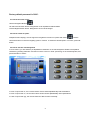
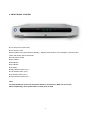
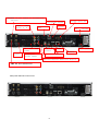
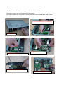
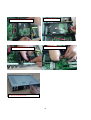
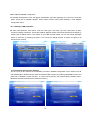
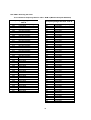
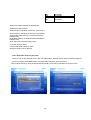
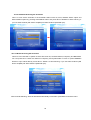
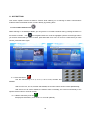
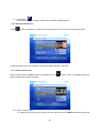
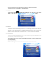
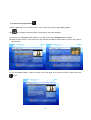
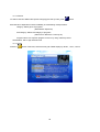
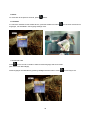
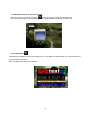
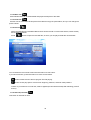
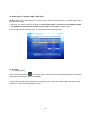
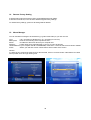
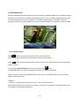
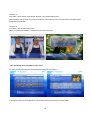
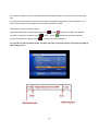
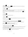
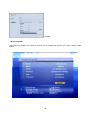
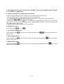
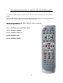
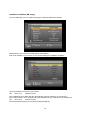
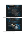
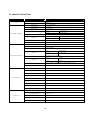
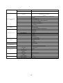
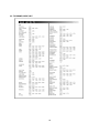
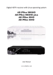
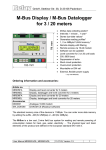
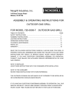
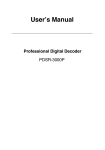
0. INTRODUCTION
Welcome to the world of new High Definition Digital Receiver that will make your life richer and closer to
your dream. Before using your new receiver, we recommend you to read this manual carefully for your own
safety and correct operational manual. This product is fully compliant with the DVB standards and transmits
digital broadcasting service directly to your TV
The STB is easy to use and adaptable for future upgrade. The software is to be upgraded continuously to
improve the function.
1. SAFETY INFORMATION
Please read the following recommended safety caution carefully for your safety
“DANGER OF THE HIGH VOLTAGE AND RISK OF ELECTRIC SHOCK!”
Power Supply: 110-220V AC 50/60Hz
The socket-outlet shall be installed near the equipment and shall be easily accessible.
Allow clear space around the STB for sufficient ventilation.
Never place the STB on soft furnishing or carpet.
Do not stack other electronic equipment on top of the STB.
Use a soft/dry cloth and a mild solution to clean the exterior of the STB.
Never allow liquids. The inside of the STB shall not be exposed to dripping, spray or other objects filled with
liquids.
Do not use any attachments that are not recommended.
Do not allow the unit to be exposed hot, cold or humid conditions.
Service should be carried out only at a qualified service agent.
Do not connect or modify cables when the STB is plugged in.
Do not remove the cover.
Warning:
AB-COM s.r.o. company does not hold any responsibility for any harms caused by using unofficial or illegal
software.
AB-COM s.r.o. company warns that watching of european Pay TV channels on European Union territory
without paying all corresponding abonent fees is illegal.
If anybody uses any of products of AB-COM s.r.o. company in order to watch Pay TV channels without correct
paying he does it on his own responsibility and and will carry all potential legal effects.
2. HOW TO USE THIS MANUAL
This manual provides complete instructions for installing and using the STB. The following symbols will be
served as follows.
Symbol
Explanation
1. MENU (Capital & Bold)
Represents Main Menu category.
1.1. Menu(Bold)
Represents a sub-category of the main menu
1.1.1. Menu
Indicates a selectable option in a sub-category.
Press the MENU key on the RCU (Remote Control Unit) to enter into the main menu.
In some menus, you are asked to put the PIN (Personal Identification Number) code as a password.
2
Factory default password is '0000'.
2.1 How to move the cursor
Use the Navigation Buttons
UP and Down Direction button: Navigate the cursor Upwards and Downwards.
Left and Right Direction button: Navigate the cursor Left and Right
2.2 How to select an option
OSD(On Screen Display)- menus support to navigate the functions or options with these
buttons.
Use these buttons to reach the targeting option or function. To select the desired option or function, press OK
button.
2.3 How to use the virtual keyboard
In some menus, you are asked to put alphabetical characters on the virtual keyboard. Select each alphabet
character by pressing OK button. and then move the cursor on “Save” (Save key) on the virtual keyboard, and
press OK button to save it.
In case of input mode “a”, the numeric buttons of RCU works alphabetically with Small letters
In case of input mode “A”, the numeric buttons of RCU works alphabetically with Capital letters
In case of input mode “@”, the numeric buttons of RCU works numerically
3
3. BEFORE YOU BEGIN
3.1 Advanced Features
DVB compliant DVB-S, DVB-S2, DVB-T, DVB-C supported
Smart tuner supported(Plug & Play)
MPEG-2 MP@HL Video Decoder
MPEG-4 AVC/H.264 HP@L4 Video Decoder
DIVX supported
MP3 decoder
Dolby AC3 DownMix decoder
HDMI v.1.2A with HDCP supported
Multi-format Audio Decoder
High Definition and Standard Definition
DVB Common Interface (2 slots) supported
Format resolution: 1080i, 720p, 576p
USB 2.0(Host) supported
USB 1.0(Client) supported
Network Interface Supported (high speed Ethernet)
VFD Display : Capability for display of various information
SCPC and MCPC receivable from C/Ku-band satellites
Channel list editing
Favorite channel list editing
True-color On-Screen Display (OSD)
Full Picture In Graphic (PIG) function
Electronic Program Guide (EPG) for on screen channel information
Subtitle & Teletext supported
Parental lock facility by channel and program event
LINUX open source (some parts under the terms of GPL, accordingly expandable)
4. THE CONTENTS OF THE BOX
Please make sure that the following items are included in the Package.
STB main unit
Remote Control Unit
2 Batteries (size AAA ALKALINE)
Operation Manual
4
5. REMOTE CONTROL UNIT (UNIVERSAL TYPE)
Audio mute
Switch On /
RCU respond to TV
RCU respond to STB
Sub picture position
in PIP mode
Swap Picture
Sub
channel
list in PIP
PIP on/off
Recall
Volume +,Page
up/down
Program up/down
or
Info banner
Electronic
Program
Favorite
Recorded
Book or check mark
To exit from the OSD menu
Main Menu or previous
menu
Navigation buttons
or Vol+,- Ch+,-
Photo
Album
Music
Fast forward or random play
Record
Pause
Repeat
Playback
or
return to live
Multifeed
Alternate
audio
Slow motion with
rate
Teletex
Fast reverse
random play
or
Stop
5
Subtitle
5.1. Programming the remote control for your TV set.
This Universal type remote control works for both TV and PVR.
There are two ways to program the remote control; Automatic Code Search and Direct Entry.
5.1.1 Using automatic code search
1. Turn on the component (TV) you want to control.
2. Press and hold the TV button until the LED (TV button) turns on red, then release the key.
3. Point the remote at the component (TV), press and release the UP (
) button, and then wait three
seconds or until the LED stops flashing.
At this point the remote control is searching for the correct code to program. If, after three seconds, the
component (TV) you want to control does not turn off, press and release UP ( ) button again to make
the remote to search the next set of codes.
4. If the component you want to control does turn off; Press and release OK button, then the LED blinks
three times.
5.1.2. Using direct entry method
1. Turn on the component (TV) you want to control.
2. Locate the Code List (refer to code list on the page 59). Find your TV brand that you want to control.
3. Press and hold the TV button until the LED on the remote control turns on red, then release the key.
4. Enter 3-digit code from the code list, then the LED blinks three times.
5. If you get no response, repeat these steps using the next code listed for your TV brand until the
component responds to the remote control command.
5.1.3. Locking the volume control.
Locking the volume controls to a single device makes it easier to control volume, without having an
unexpected volume change. If you lock the remote's volume controls to the TV set, you will be always
able to change the volume to the level you want, without having adjusting it twice on multiple devices.
If you want to lock the volume for the TV system;
1. Press and hold the STB component key until the LED on the remote control turns on.
2. Enter 3-digit code, 9 9 9 .
3. Press and release the STB component key, then the LED blinks three times.
5.1.4. Unlocking the volume control.
If you want to unlock the volume for the STB component;
1. Press and hold the STB button until the LED on the remote control turns on.
2. Enter 3-digit code, 9 9 9 .
3. Press and release the STB component key, then the LED blinks three times.
NOTICE: Find the TV brand code list on the page 44.
6
6. FRONT PANEL CONTROL
Two slots for the smart cards
Two slots for CAM
MVFD (Matrix Vacuum Fluorescent Display) – displays channel name, error messages, current time and
status and remote control commands
Power button On/Off
Menu Button
EPG Button
FILE Button
OK button
Right direction button (Vol +)
Left direction button (Vol -)
Up direction button (CH +)
Down direction button (CH -)
Note:
Cold off (Shutdown): Press and hold power button on front panel or RCU over 2 seconds.
Warm off (Standby): Press power button on front panel or RCU
7
Stand by mode
TV channel
Radio channel
Actual channel is satellite
Actual channel is terrestrial
* If none of these symbols is highlighted then actual program is cable (DVB-C)
A file record from HDD is being playied
Recording
Normal watching, timeshift or file playback
Timeshif activated on live program
Scheduled Timer event in Standby mode.
* It does not indicate when STB is turned off
Actual channel (record) is in HD format
There is a device connected to USB host
Actual channel is locked or STB is locked
Actual channel is in Dolby Digital audio format
Mute function is activated
Indication of operation tuner/tuners
MP3 playback
Repeat of selected section
Video resolution of actual program
7. REAR PANEL CONNECTIONS
8
ANTENNA IN for Cable or Terrestrial
antenna
Telephone MODEM
CVBS
and
Audio L, R
TV
and
SCART
Tuner
2
S-vid
HDD
VCR
Component
Video YPbPr
Serial port RS
AC
USB 1.1
client
HDMI
AC
Ethern
USB Host 2.0
Optical Digital Audio for Digital
LNB IN for Satellite
Rear panel with built-in two tuners:
9
on/off
power
8. INSTALLATION
Most effective and common setting methods are suggested below. Please follow the instructions carefully.
8.1 Connection with Satellite dish
Analog Video : TV SCART(CVBS, YUV, RGB), RCA(CVBS), Components(Y Pb Pr), S-video(Y/C)
Analog Audio : TV SCART(L,R), RCA(L,R)
Digital Video : HDMI
Digital Audio : HDMI, S/PDIF
10
8.2 Connection with Terrestrial Antenna or Cable network
Analog Video : TV SCART(CVBS, YUV, RGB), RCA(CVBS), Components(Y Pb Pr), S-video(Y/C)
Analog Audio : TV SCART(L,R), RCA(L,R)
Digital Video : HDMI
Digital Audio : HDMI, S/PDIF
11
Connection of HD (High Definition) signal:
If you dispose of TV or other type of displey that supports High Definition resolution (marked as “HD ready” or
“Full HD”) connect your STB with this display via HDMI connector. Using such a connection the video and
audio signal is transferred digitally in best.
You can also use Component analog YPbPr output for transfering video signal. Audio must be connected
separatelly via CINCH L/R connectors (analog – just stereo) or via optical digital S/PDIF output.
Connection of SD (Standard Definition) signal:
If you want to connect your STB with SD (Standard Definition) TV display you can use HDMI or YPbPr
connectors if your TV is equipped with it (signal will be transfered in SD - 576i resolution).
You can also use other types of connections (ordered downward according to quality): TV SCART in RGB or
YUV mode, S-Video (Y/C), CINCH (CVBS), TV SCART (CVBS). None of these connection supports High
Definition output. If you receive HD signal and you use some of these connections finalreceived signal will be
just in SD quality.
Audio signal can be connected via:
- analog stereo outputs: TV SCART(L,R), CINCH(L,R)
- digital outputs: HDMI or S/PDIF
12
8.3. Tuner module and HDD bracket connection into the main board
The receiver supports 3,5” S-ATA HDD with no size limitation.
The receiver supports any combination of two Plug and Play tuners: DVB S, DVB S2, DVB T, DVB C.
Warning: Always reconnect power cord before unmounting the cover.
2. Put first tuner connector and locate the tuner
module on the socket through slide of guide wing
1. open the top cover
4. Put second tuner as first tuner
3. Remove empty tuner cover.
5. Assemble HDD and brackets with screws
6. Insert HDD brackets into the guide hole
13
7. Connect HDD power cable of SMPS
9. Bend SATA cable as picuture
8. Connect SATA cable
10. Bend SATA cable as picture
11. Screw in to fix the top cover
14
9. BEFORE SETTING
9.1 Menu Information
Selectable lines are generally activated (highlighted). No-activated lines are not selectable.
Most of OSD- menu show short information at the bottom of the screen.
9.2 Basic Key Control
With the UP/DOWN direction button you can move the cursor upwards and downwards in the OSD (On
Screen Display) menu. When you have reached the desired option or function, press the OK button to confirm
your choice.
In case of changing TV channel you can only press UP/DOWN direction button.
In most of menu, you can select menu items with LEFT/RIGHT direction button.
When you want to return to the previous menu with saving the change, press the MENU Button.
When you want to exit from the current menu, press the EXIT button.
10. GET STARTED FOR THE FIRST TIME
If it is the first time using the STB, you should set parameters for system configuration and scan the channels.
Follow setup procedure for scanning the channel. When you have finished the procedure, you can start
watching TV or listening to the Radio.
10.1 Switch your TV and STB On.
The Local Time setting menu will appear automatically.
10.2. Selecting language and Adjusting the local time.
Select Language Setting menu to set suitable language for different items - Menu language, Audio language,
Subtitle language and Teletext character set. Press UP/DOWN buttons to select desired item and press OK.
Use LEFT/RIGHT buttons to select desired language.
Press EXIT to enter Local time settings menu. Select proper Time zone (e.g. for Slovakia and Czech Republic:
GMT + 01::00) and activate (or deacivate) Dylight Saving.
Set Time mode (12 or 24 hours) and Time setting – if you set „from SAT“ press „Time update“ and time will be
set automatically from satellite. If you set „manual“ you will have to set up time and date manually.
15
Press EXIT to enter antenna configuration menu. Select your configuration and start scanning or press EXIT to
enter Main menu.
10.3. Menu tree.
Service Searching
**Satellite Configuration
**DiSEqC 1.2
**USALS
TP& Channel Edit
Channel Scan
Main Menu
Service Searching
System Settings
Advanced Setup
Parental Lock
Common Interface
Multimedia
Plug-in
Information
System
Settings
Local Time Settings
A/V Settings
OSD Settings
Language Settings
Sleep & Wake up time
Power Control
** Only satellite system use
Multimedia
File List
Scheduled Record List
Music List
Photo Album List
Advanced Setup
IP Setup
HDD Setup
Mount Manager
Network Update
Factory Reset
Informatio
System Information
Network Information
HDD Information
Tuner Information
(Menu Tree)
16
10.4. DVB-S/S2 Satellite Configuration
The Satellite Configuration menu will appear automatically right after adjusting the Local Time. Press OK
button. Empty list of satellites appears. Press Yellow function button (Add satellite) to enter Satellite
Configuration menu.
10.4.1 Setting of LNB parameters
Set each LNB parameter: SAT Name, Tuner ID, LNB Type, Local Freq, TP Freq, LNB Power, 22 KHz,
Toneburst, DiSEqC Parameter, Uncomitted, DiSEqC Repeats, Swap Commands and Sequence Repeat by
pressing LEFT/ RIGHT button or OK button as your LNB and dish aimed. You can see whole selectable
values of each item by pressing OK button. You will see the Signal indicator as yellow and green if all
values are set correctly.
10.4.2 Automatic Scanning the satellites
This is to scan all the channels of the satellites you setup in Satellite Configuration menu. Select Tuner ID
and Satellite Name, Network Search option and Search Method option by pressing LEFT/RIGHT button and
press OK on SEARCH to start scanning. To cancel scanning during the progress press CANCEL button.
Meantime searched channels will be stored into memory.
17
10.4.3. Manual Scanning the satellite
Select Manual field to scan channels on specific TP. Set Tuner ID, Satellite Name, Frequency, Modulation,
Symbol Rate, Polarity values and Network searching.
You can press OK to check the values on Frequency and Symbol Rate menu or press NUMERIC buttons
to input values directly. Press OK on Search to start scanning.
You can also start searching by pressing Blue function button.
Advanced Search :
Video PID: Enter the correct VIDEO PID value by using numeric buttons on the RCU.
Audio PID: Enter the correct AUDIO PID value by using numeric buttons.
PCR PID: Enter the correct PCR PID value using numeric Buttons.
After channel searching, channels are listed automatically. Press OK or press EXIT to leave the
menu.
18
10.5. DVB-C Scanning the Cable
10.5.1. Reference frequency table for cable – DVB-C (Western European Standard)
Frequency Range Hyperband PAL-G
Channel
Center Frequency
S02
113±4 MHz
S03
121±4 MHz
S04
128,50±3,50 MHz
S05
135,50±3,50 MHz
S06
142,50±3,50 MHz
S07
149,50±3,50 MHz
S08
156,50±3,50 MHz
S09
163,50±3,50 MHz
S10
170,50±3,50 MHz
S11
233,50±3,50 MHz
S12
240,50±3,50 MHz
S13
247,50±3,50 MHz
S14
254,50±3,50 MHz
S15
261,50±3,50 MHz
S16
268,50±3,50 MHz
S17
275,50±3,50 MHz
S18
282,50±3,50 MHz
S19
289,50±3,50 MHz
S20
296,50±3,50 MHz
S21
306±4 MHz
S22
314±4 MHz
S23
322±4 MHz
S24
330±4 MHz
S25
338±4 MHz
S26
346±4 MHz
S27
354±4 MHz
S28
362±4 MHz
S29
370±4 MHz
S30
378±4 MHz
S31
386±4 MHz
S32
394±4 MHz
S33
402±4 MHz
S34
410±4 MHz
S35
418±4 MHz
S36
426±4 MHz
S37
434±4 MHz
S38
442±4 MHz
S39
450±4 MHz
S40
458±4 MHz
S41
466±4 MHz
Frequency Range UHF IV/V - PAL-G
Channel
K21
K22
K23
K24
K25
K26
K27
K28
K29
K30
K31
K32
K33
K34
K35
K36
K37
K38
K39
K40
K41
K42
K43
K44
K45
K46
K47
K48
K49
K50
K51
K52
K53
K54
K55
K56
K57
K58
K59
K60
K61
K62
K63
K64
K65
K66
19
Center Frequency
474±4 MHz
482±4 MHz
490±4 MHz
498±4 MHz
506±4 MHz
514±4 MHz
522±4 MHz
530±4 MHz
538±4 MHz
546±4 MHz
554±4 MHz
562±4 MHz
570±4 MHz
578±4 MHz
586±4 MHz
594±4 MHz
602±4 MHz
610±4 MHz
618±4 MHz
626±4 MHz
634±4 MHz
642±4 MHz
650±4 MHz
658±4 MHz
666±4 MHz
674±4 MHz
682±4 MHz
690±4 MHz
698±4 MHz
706±4 MHz
714±4 MHz
722±4 MHz
730±4 MHz
738±4 MHz
746±4 MHz
754±4 MHz
762±4 MHz
770±4 MHz
778±4 MHz
786±4 MHz
794±4 MHz
802±4 MHz
810±4 MHz
818±4 MHz
826±4 MHz
834±4 MHz
K67
K68
842±4 MHz
850±4 MHz
K69
858±4 MHz
Western European Standard for QAM Boxes:
QAM Linear Channel Scan:
Start Frequency: 306 MHz (center freq. channel S21)
Stop Frequency: 858 MHz (center freq. channel K69)
Symbol Rate: 6900, 6875, 6111 kS/s (Auto/Manual,
Default=Auto)
Modulation Scheme: 64/128/256 QAM (Auto/Manual,
Default=Auto)
Outer FEC scheme: RS(204/188), None
Inner FEC scheme: None
Channel Bandwidth: 8MHz or 7MHz
Spectrum shape: Inverse, Normal
10.5.2. Automatic Scanning the Cable
This is to scan all the channels of the cable. Set Cable Name, Network Search option and Search Method
option by pressing LEFT/RIGHT button and press OK on SEARCH to start scanning.
After channel searching, channels are listed automatically. Press OK or press EXIT to leave the menu.
20
10.5.3. Manual Scanning the Cable
This is to scan channels on specific channel. Set Tuner ID, Region, Modulation, Frequency and Symbol
Rate. You can press OK to check the values on Frequency and Symbol Rate on menu or press NUMERIC
buttons to input values directly. Press OK on Manual Search to start scanning. If you input new channel
data in this menu, the new data will be saved in the data base automatically.
After channel searching, channels are listed automatically. Press OK or press EXIT to leave the menu.
10.6. DVB-T Scanning the Terrestrial
10.6.1. Reference frequency table for terrestrial
There are three kinds of region selecting method according to frequency bandwidth.
1. Germany.
2. Australia.
3. Other countries as Western EU (U.K, Italy, France, Spain, China, Finland, Sweden).
DVB-T/H Channel Frequency
U.K, Italy, France, Spain
China, Finland, Sweden
Germany
Ch.
1
2
3
4
5
6
7
8
9
Frequency
0
0
0
0
177,500
184,500
191,500
198,500
205,500
BW
7M
7M
7M
7M
7M
7M
7M
7M
7M
Ch.
1
2
3
4
5
6
7
8
9
Frequency
0
0
0
0
178,750
186,750
194,750
202,750
210,750
BW
8M
8M
8M
8M
8M
8M
8M
8M
8M
21
Australia
Ch.
2
3
4
5
6(8)
7(9)
8(10)
9(11)
9A(12)
Frequency
0
0
0
0
177,500
184,500
191500(625)
198,500
205,500
BW
7M
7M
7M
7M
7M
7M
7M
7M
7M
10
11
12
13
14
18
19
20
21
22
23
24
25
26
27
28
29
30
31
32
33
34
35
36
37
38
39
40
41
42
43
44
45
46
47
48
49
50
51
52
53
54
55
56
57
58
59
60
61
62
63
64
65
66
67
68
69
212,500
219,500
226,500
0
0
0
0
0
474,000
482,000
490,000
498,000
506,000
514,000
522,000
530,000
538,000
546,000
554,000
562,000
570,000
578,000
586,000
594,000
602,000
610,000
618,000
626,000
634,000
642,000
650,000
658,000
666,000
674,000
682,000
690,000
698,000
706,000
714,000
722,000
730,000
738,000
746,000
754,000
762,000
770,000
778,000
786,000
794,000
802,000
810,000
818,000
826,000
834,000
842,000
850,000
858,000
7M
7M
7M
8M
8M
8M
8M
8M
8M
8M
8M
8M
8M
8M
8M
8M
8M
8M
8M
8M
8M
8M
8M
8M
8M
8M
8M
8M
8M
8M
8M
8M
8M
8M
8M
8M
8M
8M
8M
8M
8M
8M
8M
8M
8M
8M
8M
8M
8M
8M
8M
8M
8M
8M
8M
8M
8M
10
11
12
13
14
18
19
20
21
22
23
24
25
26
27
28
29
30
31
32
33
34
35
36
37
38
39
40
41
42
43
44
45
46
47
48
49
50
51
52
53
54
55
56
57
58
59
60
61
62
63
64
65
66
67
68
69
218,750
0
0
0
0
0
0
0
474,000
482,000
490,000
498,000
506,000
514,000
522,000
530,000
538,000
546,000
554,000
562,000
570,000
578,000
586,000
594,000
602,000
610,000
618,000
626,000
634,000
642,000
650,000
658,000
666,000
674,000
682,000
690,000
698,000
706,000
714,000
722,000
730,000
738,000
746,000
754,000
762,000
770,000
778,000
786,000
794,000
802,000
810,000
818,000
826,000
834,000
842,000
850,000
858,000
8M
8M
8M
8M
8M
8M
8M
8M
8M
8M
8M
8M
8M
8M
8M
8M
8M
8M
8M
8M
8M
8M
8M
8M
8M
8M
8M
8M
8M
8M
8M
8M
8M
8M
8M
8M
8M
8M
8M
8M
8M
8M
8M
8M
8M
8M
8M
8M
8M
8M
8M
8M
8M
8M
8M
8M
8M
22
10(13)
11(14)
12(15)
13
14
18
19
20
21
22
23
24
25
26
27
28
29
30
31
32
33
34
35
36
37
38
39
40
41
42
43
44
45
46
47
48
49
50
51
52
53
54
55
56
57
58
59
60
61
62
63
64
65
66
67
68
69
212,500
219,500
226,500
0
0
0
0
0
0
0
0
0
0
0
522,500
529,500
536,500(625)
543,500
550,500
557,500
564,500
571,500
578,500
585,500
592,500
599,500
606,500
613,500
620,500
627,500
634,500
641,500
648,500
655,500
662,500
669,500
676,500
683,500
690,500
697,500
704,500
711,500
718,500
725,500
732,500
739,500
746,500
753,500
760,500
767,500
774,500
781,500
788,500
795,500
802,500
809,500
816,500
7M
7M
7M
7M
7M
7M
7M
7M
7M
7M
7M
7M
7M
7M
7M
7M
7M
7M
7M
7M
7M
7M
7M
7M
7M
7M
7M
7M
7M
7M
7M
7M
7M
7M
7M
7M
7M
7M
7M
7M
7M
7M
7M
7M
7M
7M
7M
7M
7M
7M
7M
7M
7M
7M
7M
7M
7M
10.6.2. Automatic Scanning the Terrestrial
This is to scan all the channels of the terrestrial. Select Tuner ID, Area, Network Search option and
Search Method option by pressing LEFT/RIGHT button and press OK on SEARCH to start scanning. If
you use active antenna (with built-in amplifier) set Active Antenna parameter (On).
10.6.3. Manual Scanning the Terrestrial
This is to scan channels on specific channel. Set Tuner ID, Channel Number, Frequency and Bandwidth.
You can press OK to check the values on Frequency and Symbol Rate on menu or press NUMERIC
buttons to input values directly. Press OK on “Search” to start scanning. If you use active antenna (with
built-in amplifier) set Active Antenna parameter (On).
After channel searching, channels are listed automatically. Press OK or press EXIT to leave the menu.
23
11. HOT BUTTONS
This section explains various hot button’s function while watching TV or listening to Radio. These buttons
enable to reach the desired function or menu directly by pressing them.
11.1 TV or Radio Channel List
While watching TV or listening to Radio, you can get the ‘TV or Radio a Channel List by pressing OK button on
the remote controller. Use
the navigation-buttons to move the highlights up/down and left /right. When
you reach a channel that you want to check, press OK button for a view. To move to a channel that you have
chosen, press OK button again.
11.1.1 Sort channel list
Sort the channels by A to Z, Z to A, FTA to CAS, Provider and
Satellite.
With sort of A to Z, Z to A, Provider and Satellite, the numeric buttons of RCU works alphabetically,
With sort of FTA to CAS or default, the buttons works numerically, the cursor moves directly to the
specific channel name or channel number.
11.1.2 Select Channel by tuner ID
It displays channel list by Tuner ID as 1 or 2 or both (default).
24
11.1.3. Jump Move
The cursor moves by a sorting condition like numerically or alphabetically.
11.2. Edit in the Channel List
Press
button on the RCU in channel list menu (OK button for channel list) for Channel Edit mode.
It supports Delete, Hide, Lock, Rename, Volume level, Move channel or channels
11.3. Favorite Channel List
Favorite Channel list is available anytime by pressing the FAV
button on RCU. The default groups are
Sports, Drama, News, Movie and Music.
11.3.1. New Favorite Group
To create a new favorite group, move the cursor to right and choose “Make Fav List” and press OK
25
button to bring virtual key board and create new favorite group with the virtual keyboard.
To save the new group, Press ENTER on the virtual keyboard.
11.3.2. Delete
To remove the marked (
“Delete”
and
press
) channel in the favorite group, move the cursor to right, choose
OK
button.
11.3.3. Rename
To change a channel or favorite group name, move the cursor to right, choose Rename and press
OK button to bring virtual keyboard and change the selected channel & FAV group, and then press
ENTER to save the changed name and press Exit button on RCU to close the virtual keyboard.
11.3.4. Add Channels
To add new channels to Favorite list and group, move the cursor to right, choose Add Channels and
press OK button, and all channels list appears.
The high-lighted channel will be added by pressing OK button and then you can see added channels
in the selected favorite
group on the right section.
Favorite List also supports the edit functions: Move channels, Lock and Hide channels.
26
11.4. Electronic Program Guide
Press the EPG button on the remote control, and TV electronic program guide (EPG) appears.
Use
the navigation-buttons up/down and left/right to move the highlights.
If you press once, List type of EPG appears. If you press once more, Grid type of EPG appears.
Use Blue function button to move to the next day schedule and Red function button to move to the previous
day schedule.
To get more detailed EPG on specific channel, move high-lights to the channel and the content then press
button.
27
11.4.3. Search
To search channel’s EPG under specific category/genre that you like, press
button
EPG data show dependent on EPG availability of broadcasting media providers.
Category: Select genre of programs.
(Movie/News/ Sports etc)
Sub Category: Select sub-category of programs
(Adult movie / Romance / Comedy etc)
Program name: Put a specific program name in it by using virtual key board.
Classification: Set an age restriction limit.
11.4.4. Zoom
Press the
button of the RCU, select the time-grid of EPG display by 30 Min, 1 hour, 2 hours.
28
11.5. Channel Information
Info banner appears by pressing
button. If you press twice, channel details are also available. The info
bar shows all necessary information about the selected channel.
Any highlighted icon in yellow on the info banner indicates the availability of the services.
Channel name
EPG
Channel Number
Start Time
Channel
Signal
29
11.6 RCL
To move back to the previous channel, press
button.
11.7 Subtitle
If a channel is available for the subtitle service, press the subtitle icon button
. If it services more than two
languages, it is selectable in the language settings menu.
11.8 Alternate audio
Press
on the remote controller to select an audio language and sound mode:
(Mix / Mono Left / Mono Right),
Audio languages are selectable by pressing Left/Right direction button. Press
30
or EXIT key to exit.
11.9 Multifeed function for Premiere channel
When you move to ‘main feed’ and press
button of remote controller then Multifeed List
(sub-channels) will appear. Use Up/Down buttons to select desired sub-channel and press OK.
11.10. OSD teletext.
OSD teletext is available if served. If the teletext icon on Info Banner is appeared the icon, press this button to
see the teletext information.
Note: VBI teletext function is not supported,
31
11.11. PIP(Picture in Picture) and PAP(Picture and Picture).
Subchannel list
or Subscreen
PAP
Close
: you can see two channels on the screen, one main channel, the other sub-channel (it can be two
channels from different satellites or TP if you use two tuners).
If press this button once more, PAP on the screen
: you can change the location of the sub-channel.
: you can swap sub-channel and main channel, and vice versa
: you can see sub-channel list, and change the sub-channels. Or you can see recorded files with
sub-picture
Caution: two MPEG 4 channels cannot be shown on the screen at the same time, that is, not
supporting PIP function for two MPEG 4 channels.
32
11.12. Music list.
Audio files like MP3 can be downloaded and played at this place of the HDD.
11.13. Photo list
Pictures can be downloaded at this place of the HDD and enjoy the photo album, and you can change the
picture names.
11.14. File list.
All the recorded files (by Scheduled Record such as EPG record or Timer Event Record, instant record)
are recorded at this file.
Press
button to open the recorded files, in which you can play and edit the recorded files.
You can watch the file in small screen with OK button on the file name.
If you want full screen, press OK button once more or EXIT button.
button makes it back to the live program from file playing.
button shows play options such as From beginning, Resume, and book mark positions.
Caution: if you erase one or more files, it will be applied (the files will be erased) after rebooting (cold off
and on).
11.15. Internet (reserved)
This button is reserved for IPTV.
33
12. Select your TV system (1080i, 720p, PAL)
Caution: When the TV SYSTEM (your TV type) does not match to the STB setting, TV screen and/or audio
may not show properly.
In that case, you need to switch off the STB, and press Power button -> then press and hold Menu button
-> use Up/Down direction button to select your TV system -> press OK on the front panel.
If you can open and see the Main menu, you can adjust on the AV Settings menu.
13. IP setup
13.1. Manual setting
Use the Navigation Buttons
and directly enter numeric values of corresponding parameter (IP Address,
Subnet Mask, Gateway) and then press SUBMIT.
You must also manually set parameters when connecting your receiver with another STB or PC without using
a switch or a router. Use crossed Ethernet cable.
34
Example for direct connection:
Receiver (1) :
IP Adress
Subnet Mask
Gateway
192.168.1.20
255.255.255.0
192.168.1.135
Receiver (2) or PC :
IP Adress
192.168.1.21
Subnet Mask 255.255.255.0
Gateway
192.168.1.135
13.2. AUTO (DHCP)
For the VDSL or ICS client users.
It detects values automatically. No need to enter any values here. After selecting Auto(DHCP), press submit
button to have all settings show up automatically. If LAN cable is not properly connected, all settings might
appear as “0.0.0.0.” In this case, check the cable connection and retry it.
13.3. AUTO (PPPoE)
For the ADSL users
ID and Password (which acquired from internet service provider) are required here; enter the values by using
virtual Keyboard. Press OK button to bring the Virtual Key board.
13.4. AUTO (PPP)
For the Dial up MODEM users
ID and Password (which acquired from internet service provider) are required here; enter the values by using
virtual Keyboard. Press OK button to bring the Virtual Key board.
35
14. Restore Factory Setting
It requires PIN code to access the Factory reset (Default PIN code: 0000).
It removes Channel List, FAV List and it restores original factory settings.
To restore factory settings, press ok. All settings will be deleted.
15. Mount Manager
You can use Mount manager to share directory (e.g. MP3 music files) on your PC via LAN.
Type
Mount point
Server
Directory
User/Password
Active
(cifs : accessing to Windows PC, nfs : accessing to Linux PC)
Point for the mounting of the mp3 files in STB
IP address of the server PC that your computer has
Folder name where mp3 files exist in your PC. It has to be shared.
If your computer has ID or PASSWORD, insert them. If not exist, leave it as a blank or default.
Select ‘yes’ and then click on ‘Mount’ button at the bottom of the screen.
Caution:
In case that your computer is switched off or disconnected, click on ‘Unmount’ button. Otherwise it can cause
some problem such as longer booting time.
36
16. PVR OPERATION
Receiver enables simultaneous recording of two channels and 1 recorded file playback. If the STB is equipped
just with one tuner then both recorded programs must be from one TP, If the STB is equipped with two tuners
the recorded programs can be from different TP or satellites. Simultaneously it is possible to watch live
program (must be from the same satellite as one of two recorded programs) or playback an record from HDD.
16.1. Instant Recording
Press
button to record the channel that you are currently watching.
In the channel list, a channel in red indicates the currently recording channel.
Press
button to stop recording. Select a channel name that you want to stop recording, and press OK
button to confirm.
If you need to adjust the duration in the record channel, press
button.
The default duration is two hours; the duration can be set up to maximum 23h 59min.
When Time Shift is set ON in the HDD setup menu, the instant recording point depends on the Time Shift
setting in HDD setting menu.
Condition 1
Time Shift – ON & Include Time Shift On Record – YES in HDD Setting menu
With the above setting, when you press record button, it records from the beginning of timeshift buffer on the
Time Shift bar on the bottom of the screen.
37
Condition 2
Time Shift – ON & Include Time Shift On Record – NO in HDD Setting menu
With the above setting, when you press record button, it records from the current live point and timeshift buffer
disappears automatically.
Condition 3
Time Shift – OFF in HDD setting menu
When you press record button, it records from the current live point
16.2. Scheduled Record by EPG or timer event
To show currently recording files and reserved recording list on the Menu.
A recording notice pop-up will appear for 10 minutes before the reservation recording starts.
38
If the STB is in standby mode, the scheduled records automatically begin 10 minutes prior to the scheduled
time.
If you press the power button on RCU while recording, a message box appears for your confirmation if you
want to stop recording. Press OK button to save the recorded file on HDD.
Reservation recording on the EPG menu:
Select desired program on EPG content and press
program is reserved for recording. Press
program is reserved for zapping. Press
. Symbol
again – symbol
appears that means that selected
appears that means that selected
once more to cancel reservation.
It is possible to set time offset before and after real time of planned program (according the EPG) in
HDD settings menu:
39
16.3. Timeshifting on live channels.
Timeshifting on a live channel is available when set Time Shift – ON in HDD setting menu . When a channel is
zapped to others, the recorded file will disappear automatically, then it starts to record the current live channel.
On live channel, all kinds of the PVR functions are available such as Pause, Jump back, Jump forward,
Rewind, Fast forward, Slow motion, Frame by frame play.
16.4 Book mark
Press the
button, to make a bookmark on the time bar where you want. If you want to move to the
next bookmark press PLAY button to jump to the next bookmark. Press
remove it from time grid.
40
button on specific bookmark to
16.5. Play
Press the button under the book mark (
) on the display time bar to jump to the next book mark, and it
starts playback from the marked point.
16.6. Repeat
Press the button to repeat the portion of the recorded file between any two neighboring bookmarks. Press the
button and hold over 2 seconds to repeat the whole file.
If there is no bookmark , you have to repeat the whole file. To exit from the repeat function, press
button
once more.
16.7. Stop
To stop playing the file and back to a live channel.
16.8. Pause
To pause file playing, press this button once. To resume playback, press this button once more. To go back to
normal play mode, press Play (
) button.
16.9. Fast forward/ Fast reverse or random position jump & playback
To move the time bar forward/ backward x2, x3, x4, x5 speed rate by pressing a button shortly, and if you
press PLAY (
)button, it is back to normal speed mode.
If you keep pressing the button, the time bar moves as fast as you desire.
16.10. Slow motion and Frame by Frame
If you keep pressing the button for 1~2 seconds and release, it plays slow motion. If press the button more and
more, it changes slow rate like x1/2, x1/3, x1/4, x1/5.
If you press the button shortly, it plays frame by frame. As you press the button more and more, it moves
picture by picture. Press PLAY
button to move back to normal play mode.
41
18. Information
18.1. System Information
It displays information about software and hardware configuration of the receiver:
Version/model of receiver
Micom Version
Boot Version
Image (firmware) Version
DB Version (database)
PCB Version (motherboard)
Product ID
First time activation date
18.2.Network Information.
It displays network info such as IP address, Subnet mask, Gateway etc.
18.3. HDD information
It displays product name of HDD, HDD capacity, Free space
18.4. Tuner information
It displays which kinds of tuner inserted like as DVB-T, DVB-S, DVB-S2, DVB-C, PLL, model name of the
demodulator, part name of the tuner.
19. SOFT WARE UPGRADE
< USB Driver installation >
For the first time, follow the instructions from 1 to 13. This procedure is required for initial use for once.
1. Download and install the Flash tools(version 1.0.2) program on your PC
2. AC power Off in the rear panel or press power button and OK button simultaneously on the front panel.
42
(This is to make Cold Off mode)
3. Connect between your PC and STB with USB Cable
4. AC Power On.
5. Press and keep holding the Power button and press + right direction button on the front panel, and you see
“USB UPGRADE” in the front panel.
6. PC detects new hardware device (important) to INSTALL the USB driver
7. Driver Installation Wizard Appears
8. Select ‘install from a list or specific location (advanced)’ and click ‘Next’.
9. Select ‘Include this location in the search’ and click ‘Browse’
10. Designate the folder at C:/Program files/Flash_tools) and click ‘Next’
11. Wizard will search the driver file.
12. Select ‘USB FOR VESTA – c;/windows/inf/vestausb.inf’ and click ‘Next’
12.1. If it asks system file in some case, Browse at c:/program files/Flash_tools/vestausb and click ‘OK’
13. Click ‘Finish’ when it is done.
Important: The order of this procedure is very important; please do follow the instruction step by step.
When Driver is installed successfully, it is ready to download the latest image to the STB (USB download
instructions)
< Downloading software using USB (client)>
1. Your STB and PC have to be connected by USB cable.
2. The STB has to be in ‘USB upgrade mode.
* For the ‘USB upgrade’ mode, refer to above Driver installation procedure from 1 to 5.
* Tips to make USB upgrade mode without AC Power ON/OFF or power button + + right direction button.
- If you are watching TV now, press Power button + OK button. This status is same as AC OFF/ON
which is so called ‘Cold off’.
And then, Press and keep hold the Power button + right direction button on the front panel until you see
“USB UPGRADE” on the front
3. Run the Flash Tools
4. Select ‘USB’ and check the “USB connected” in the Message box.
5. Designate the image that you want to download to the STB by pressing FILE
6. Click ‘Down’ and Wait for "DONE" on the front display.
7. If you want to download software composed of several parts designate the next part into File window and
press Down button. After finishing press Power button to reboot - your STB will be restarted
Select “ USB”
Select “ proper file”
43
complete
<Network Update>
Latest firmware (images) and welcome pictures can be updated via Ethernet port using network update
system.
44
A new functions for your receiver are available if you have installed uboot version
1.3.1 (190508 ) or newer one:
1. Software upgrade from USB memory stick (host):
- backup important data from memory stick before try to update. Remove all data from it.
- copy usb update image to memory stick and rename it: usb_update.img
- run "remove h/w(memory stick)" function on PC. You can see icon on right bottom (left of clock) screen.
- turn off the stb(
+
) and insert the memory stick.
- press and hold Standby button (
) until front display shows “BOOTING” and press UP key (on the front
side of the box, not on RC), then front display shows "USB UPGRADE" message.. uboot will update s/w with
usb_update.img from memory stick
- Wait until DONE message displays. Restart your receiver.
2. Shutdown by force :
Press power button (
) + OK(
).
3. TV resolution adjustment :
Press and hold power(
cold off mode
) button on the front panel, and press menu(
) button at the same time on
4. Serial upgrade mode :
Press and hold power(
time on cold off mode
) button on the front panel, and press right direction arrow(
) button at the same
5. HDD format by force :
Press and hold power(
) button on the front panel, and press downward direction arrow(
same time on cold off mode.
45
) button at the
Universal Remote Controller for operation with other AB IPBox models
It is possible to adjust AB IPBox AB IPBox 9000HD remote controller for operation with other AB IPBox
models.
Press and hold OK button together with corresponding number button (see lower list) for approximately 10
seconds – after finishing “STB” button will blink. Release the buttons.
Modes of operation of AB IPBox 9000HD remote controller:
OK+1 : AB IPBox 4xxS a AB IPBox 250S
OK+2 : AB IPBox 9000HD
OK+3 : AB IPBox 350Prime
OK+4 : AB IPBox 200S
OK+5 : AB IPBox 900HD
46
Installation of addons (AB image)
If you use AB image you can install several types of addons (additional modules).
Webinterface of your receiver is designated to install addons.
Find out IP address of your receiver in menu before starting an installation of addons.
Use a ftp software to connect to your receiver.
Use
name: root
password: ipbox
Copy installation file of addon (file with .ipk extension) into /tmp directory of your receiver.
Run a web browser in your computer and insert IP address of your receiver into the address line.
Use
name: root
password: ipbox
Initial web interface page of your receiver should be displayed.
47
Select „addons“ flag and confirm installation by pressing „INSTALL“ button.
Addon will be installed automatically and receiver will restart.
48
20. GLOSSARY OF TERMS
CA
Conditional Access. A system to control
subscriber access to services/ programs.
RF
Radio frequency (known as HF in some
countries).
Polarization
Enables simultaneous transmission of several
channels on the same frequency.
SCART
A 21-pin connector used for connection of
the STB, VCR and TV. Also known as
Euro connector
DVB
The Digital Video Broadcast group was
created to establish
a technical framework for the introduction of
digital video broadcasting systems.
EPG
Electronic Program Guide. The programming
information provided
By the service provider that enables a viewer
to find the much
Information of programs.
LNB (Low-Noise Block Converter)
is an essential part of a satellite receiver
which receives the signal and amplifies it for
use. It is always located with the satellite
antenna
S/PDIF
Sony/Philips Digital Interface Format
Digital audio output.
Symbol Rate
Speed of the digital transmission
TS
Transport stream.
49
21. TROUBLE SHOOTING
Problem
No display appeared on
front
Possible Causes
Power cord is not plugged
in.
What To Do
Check that power cord
No Sound/ Picture
Wrong Audio/ Video output
connection between the
Receiver and TV set.
Mute Audio
Check Audio/ Video output
connection between the
Receiver and TV set.
Press Mute button to
recover.
TV Power off
Turn TV on
No Signal
Check the cable
connections and other
equipment
connected between the
cable line and the receiver.
Wrong direction of the dish
Adjust correctly the
direction of the dish to the
cable
Wrong Video resolution for
TV
Batteries are not inserted
correctly or low.
Resetting video resolution
CA module is not working
CA module is not inserted
correctly.
Check if CA module is
inserted correctly.
Recording is not working/
Recording is stopped
No HDD space is available.
Check HDD status.
Remote controller does not
respond
Forgot PIN Code
System Halt
System Halt or Error
No EPG data
Wrong Local time
Displays “ERR 80” or “ERR
81” on front panel
Displays “ERR 82” or “ERR
83” on front panel
Communication fail with
main board with CPU
Wrong contact to tuner
module with mini-PCI socket
Displays “PANIC” on front
panel
Wrong memory use by
program
50
Check the batteries or
replace with new batteries
Contact your local service
provider/ dealer.
Press & Hold OK and
Power key on the front
panel to return to stand by
mode.
Press time update in local
time setting menu at proper
channel
Contact to A/S center
AC power off and Adjust
tuner module
Press “ power button” for
restart
Err 79
Mismatched DB version
Download proper db.img or
all-noboot.img
Err 1
CRC error
check the image
Err 2
CRC error
check the image
Err 3
Vendor ID mismatch
check the image
Err 4
Product ID mismatch
check the image
Err 5
Err 8
Mismatched
name
Mismatched
version
Erasing fail
Err 9
Flashing fail
Contact to A/S center
Err 10
Incorrect or missing install
file
check the image
Err 6
H/W
model
check the image
H/W
model
check the image
Contact to A/S center
51
22. PRODUCT SPECIFITION
Part
Type
Specifications
Type
CPU
Data/Instruction Cache
Input Connector
Input Signal Level
Frequency Range
LNB Control
Satellite QPSK Tuner(DVB-S)
Waveform
22KHz Tone
Symbol Rate
DiSEqC Control
Input Connector
Input Signal Level
Frequency Range
LNB Control
Satellite 8PSK Tuner(DVB-S2)
IEC 169-24 Female(F-type)
-65 to -25dBm
950MHz to 2150MHz
Vertical
13V(400mA Max)
Horizontal
18V(400mA Max)
QPSK(C/KU band compatible)
Frequency
22±4KHz
Amplitude
0.6±0.2V
QPSK( up to 45MS/s)
Version 1.0/1.1/1.2/USALS Compatible
IEC 169-24 Female(F-type)
-65 to -25dBm
950MHz to 2150MHz
Vertical
13V(400mA Max)
Horizontal
18V(400mA Max)
QPSK, 8PSK(C/KU band compatible)
Symbol Rate
DiSEqC Control
Input Connector
Loop through Connector
Frequency Range
Loop through Out Impedance
Band Width
Frequency
22±4KHz
Amplitude
0.6±0.2V
QPSK( up to 45MS/s),
DVB-S2 :QPSK(up to 36MS/S), 8PSK(up to 30MS/s)
Version 1.0/1.1/1.2/USALS Compatible
IEC169-2 female
IEC169-2 male
50MHz to 870MHz
75 ohms nominal
7/8 MHz
Carrier Mode
2k & 8k hierachical/non-hierachical mode
Constellation
Auto(QPSK, 16/64 QAM)
Mode Rate
Guard Interval
Input Connector
Loop through Connector
Cable QAM Tuner
32KB/16KB
Waveform
22KHz Tone
Terrestrial OFDM Tuner
266MHz ST40-202 32bit RISC CPU
Frequency Range
Loop through Out Impedance
IF Bandwidth
Auto(1/2, 2/3, 3/4, 5/6 and 7/8)
Auto(1/4, 1/8, 1/16 and 1/32)
IEC169-2 female
IEC169-2 male
47MHz to 862MHz
75 ohms nominal
8MHz
52
QAM mode
16, 32, 64,128,256QAM
Symbol rate
0.87Mbaud~7Mbaud Max.
ISO/IEC 13818-2 Specification and VC1 Microsoft video format main/advanced
profiles@HL(WMV-9)-optional, H.264
Input Stream
profiles@
Profile & Level
Input TS Data Rate
MPEG Transport Stream & A/V
Decoding
Aspect Ratio
Video Resolution
Audio Decoding
Audio Mode
Sample Rate
Flash Memory
Memory
DDR SDRAM
HDD
Digital interface for HDTV
SCART I/F
Storage & Rear connector
CVBS & Audio R/L Out
MPEG-2 MP@ML, MP@HL, MPEG4 AP@HL/H.264 level 4.1, VC1(WMV9)-optional
138Mbit/S max.
4:3, 16:9 with pan/scan vector
720 x 576(PAL), 720 x 480(NTSC), 1080i, 720P, 480i, 480P
MPEG-1 Audio Layer 1,2, Musicam
Stereo, Dual Channel, Joint Stereo, Mono
32, 44.1, and 48KHz
32MB
192MB (64MB+128MB)
Serial ATA 80/120/160/200GB and over (User Selectable)
HDMI with HDCP
VCR & TV(2 Ports)
RCA(3 Ports)
Din
S-video
Component Out(YPbPr)
Digital Audio
USB Host Interface
Data In/Out
USB Device Interface
RS232C
Network
Ethernet
Common Interface
Conditional Access
Smartcard Interface
Front Display
VFD
Input Voltage
Type
Power Supply
Power Consumption
Protection
Size (W x H x D)
Physical Specification
Weight
Operating Temperature
Environment
Storage Temperature
RCA(3 Ports)
S/PDIF via Optical
USB A-Type Female (USB 2.0)
USB B-Type Female (USB 1.0)
9 Pin D-Sub
RJ-45( 100BT )
2 PCMCIA-Cards Slots
2 Slots
Vacuum Fluorescent Display as Alpha numeric style
AC110-245V, 50/60Hz
Linear PWM
50W
- Separate Internal Fuse and Chassis
375mm x 60mm x 280 mm
3.5Kg
5 ~ 55 C
-40 C ~ +65 C
53
NOTICE
Contents of this manual and features/ Specifications of the STB are subjected to change without
notice.
TM
HDMI , the HDMI logo and High-Definition Multimedia Interface are trademarks or registered
trademarks
of HDMI Licensing LLC.
HDCP : licensed with HDCP
Dolby DigitalTM : Dolby is a trademark of Dolby Laboratories, Manufactured under license from Dolby
Laboratories
MPEG-4 AVC/H.264 : licensed with MPEG LA
MP3 Audio : MPEG Layer-3 audio coding technology licensed from Fraunhofer IIS and Thomson.
DVB-T : licensed with MPEG LA and ETSI
54
23. TV BRAND CODE LIST.
55
56
57
58
59
60
61
62
63
64
65
66
–––––––––––––––––––––––––––––––––––––––––––––––––––––––––––––––––––––––––––