1
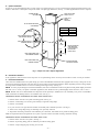
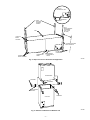
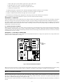
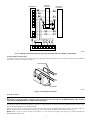
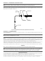
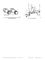
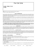
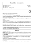
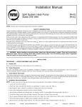
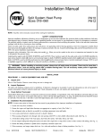
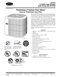
Installation Instructions
Direct Expansion Fan Coil Units
Fan Unit
FA4A, FB4A, FC4B
FH4A
NOTE: Read the entire instruction manual before starting the installation.
SAFETY CONSIDERATIONS
Improper installation, adjustment, alteration, service, maintenance, or use can cause explosion, fire, electrical shock, or other conditions which may
cause personal injury or property damage. Consult a qualified installer, service agency, or your distributor or branch for information or assistance.
The qualified installer or agency must use factory-authorized kits or accessories when modifying this product. Refer to the individual instructions
packaged with the kits or accessories when installing.
Follow all safety codes. Wear safety glasses and work gloves. Use quenching cloth for brazing operations. Have fire extinguisher available. Read
these instructions thoroughly and follow all warnings or cautions attached to the unit. Consult local building codes and National Electrical Code
(NEC) for special requirements.
. When you see this symbol on the unit and in instructions or manuals, be alert
Recognize safety information. This is the safety-alert symbol
to the potential for personal injury.
Understand the signal word DANGER, WARNING, or CAUTION. These words are used with the safety-alert symbol. DANGER identifies the
most serious hazards which will result in severe personal injury or death. WARNING signifies hazards which could result in personal injury or
death. CAUTION is used to identify unsafe practices which would result in minor personal injury or product and property damage.
WARNING: Before installing or servicing unit, always turn off all power to unit. There may be more than 1 disconnect
switch. Turn off accessory heater power if applicable. Electrical shock can cause personal injury or death.
Table 1—Accessories
ACCESSORY
Power Plug Kit (25 pack)
PART NO.
KFAPP0125PLG
KFADC0201SLP
Downflow Coil Conversion Kit*
KFADC0301ACL
KFACB0101CFB
KFACB0201CFB
Downflow Base Kit†
KFACB0301CFB
KFACB0401CFB
KFAFKO112SML
KFAFK0212MED
Filter Kits (12 packs)
KFAFK0312LRG
KFAFK0412XXL
MODEL APPLICATION
All Models
FA4A, FB4A 018-042, FC4B 024-036, 042
FH4A 001, 002
FA4A, FB4A 048-070, FC4B 038, 048-070
FH4A 003, 004
FA4A, FB4A 018, 024, FC4B 024
FH4A 001
FA4A, FB4A, FC4B 030, 036
FH4A 002
FA4A, FB4A 042-060, FC4B 033-048, 060
FH4A 003, 004
FB4A 070, FC4B 054, 070
FA4A 018, 024, FB4A 018, 024, FC4B 024, FH4A001
FA4A 030, 036, FB4A 030, 036, FC4B 030, 036, FH4A002
FA4A 042-060, FB4A 042-060, FC4B 033, 038, 042-060
FH4A 003, 004
FB4A 070, FC4B 054, 070
* Required to mount coil in unit, including condensate control parts.
† Eliminates open passage through building floor per UL and NFPA90B.
INSTALLATION
PROCEDURE 1—MOUNT UNIT
Unit can stand or lie on floor, or hang from ceiling or wall. Allow space for wiring, piping, and servicing unit.
IMPORTANT: When unit is installed over a finished ceiling and/or living area, building codes CABO M-1701.2, UMC 1205, or SBCCI 603.4
may require a field-supplied secondary condensate pan to be installed under the entire unit or unit to have a secondary condensate line.
Form:
IM-FA4A-03
Cancels:
IM-FA4A-02
Printed in U.S.A.
1-95
Catalog No.
92-33FA-4A18
A. Upflow Installation
If return air is to be ducted through a floor, set unit on floor over opening and use 1/8- to 1/4-in. thick fireproof resilient gasket between duct, unit,
and floor. Side return is a field option on slope coil models. Cut opening per dimensions. (See Fig. 1.) A field-supplied bottom closure is required.
POWER ENTRY
OPTIONS
FIELD SUPPLIED
SUPPLY DUCT
LOW VOLT
ENTRY
OPTIONS
24-IN. FRONT SERVICE
CLEARANCE
UNIT
018/024
030/036
042
A-COIL
UNITS
UPFLOW/DOWNFLOW
SECONDARY DRAIN
A
12 In.
17 In.
19 In.
1 1⁄2″
UPFLOW/DOWNFLOW
PRIMARY DRAIN
19″
A
2 1⁄2″
FIELD-MODIFIED
SIDE RETURN
LOCATION FOR
SLOPE COIL
UNITS ONLY
UPFLOW/DOWNFLOW
SECONDARY DRAIN
UPFLOW/DOWNFLOW
PRIMARY DRAIN
FIELD-SUPPLIED
RETURN PLENUM
A91424
Fig. 1—Slope Coil Unit in Upflow Application
B. Downflow Installation
In this application, field conversion of the evaporator coil is required along with an accessory base kit. Refer to Table 1 for kit part numbers.
C. Horizontal Installation
Units must not be installed with access panels facing up or down. The FH4A003 and 004 size units equipped with accessory cooling coils are not
approved for horizontal applications. All other units are factory built for horizontal left installation. When suspending unit from ceiling, dimples
in casing indicate suitable location of screws for mounting metal support straps. (See Fig. 2.)
NOTE: To ensure proper drainage for horizontal installations, unit must be installed level with its long direction and pitched slightly toward the
unit front (1/16- to 1/4-in.); for upflow or downflow applications, unit should be level or pitched slightly toward unit front (1/16- to 1/4-in.).
NOTE: Modular units can be disassembled and components moved separately to installation area for reassembly. This process accommodates
small scuttle holes and limiting entrances to installation sites. (See Fig. 3.)
HORIZONTAL RIGHT CONVERSION OF UNITS WITH SLOPE COILS
1. Remove blower and coil access panels and fitting panel. (See Fig. 4.)
2. Remove coil mounting screw securing coil assembly to right-side casing flange.
3. Remove coil assembly.
4. Lay fan coil unit on its right side and reinstall coil assembly with condensate pan down. (See Fig. 4.)
5. Attach coil to casing flange using coil mounting screw previously removed.
6. Align holes with tubing connections and condensate pan connections, and reinstall access panels and fitting panel.
Make sure liquid and suction tube grommets are in place to prevent air leaks and cabinet sweating. Install after brazing.
HORIZONTAL RIGHT CONVERSION OF UNITS WITH A-COIL
1. Remove blower and coil access panels. (See Fig. 5.)
2. Remove clip securing fitting panel to condensate pan. Remove fitting panel.
3. Remove 2 snap-in shipping clips securing A-coil in unit.
—2—
A-COIL IN
HORIZONTAL LEFT
SECONDARY
PRIMARY
FIELD
SUPPLIED
HANGING
STRAPS
24-IN.
FRONT SERVICE
CLEARANCE
(FULL FACE
OF UNIT)
UNIT
LOW VOLT
ENTRY
OPTIONS
OPTIONAL RETURN
AIR FLANGE KIT
PRIMARY
CONDENSATE
DRAIN
POWER
ENTRY OPTIONS
SECONDARY
CONDENSATE
DRAIN
1 3/4 IN.
FILTER ACCESS
CLEARANCE
A90167
Fig. 2—Slope Coil Unit in Horizontal Left Application
BLOWER BOX
2 SCREWS
2 SCREWS
REAR CORNER
BRACKET
2 SCREWS
COIL BOX
A90168
Fig. 3—Removal of Brackets on Modular Unit
—3—
COIL MOUNTING
SCREW
BLOWER
ASSEMBLY
COIL SUPPORT
RAIL
COIL SUPPORT
RAIL
SECONDARY
CONDENSATE
DRAIN
REFRIGERANT
CONNECTIONS
PRIMARY
CONDENSATE
DRAIN
A90174
Fig. 4—Conversion for Horizontal Right Applications Using a Slope Coil
A
REFRIGERANT
CONNECTIONS
AIR SEAL
ASSEMBLY
HORIZONTAL
RIGHT
APPLICATION
COIL
SUPPORT
RAIL
B
C
COIL
BRACKET
DRAIN PAN
SUPPORT
BRACKET
COIL
SUPPORT
RAIL
C
B
FACTORY
SHIPPED
COIL
BRACKET
METAL HORIZONTAL
DRAIN PAN
SECONDARY
CONDENSATE
DRAIN
PRIMARY
CONDENSATE
DRAIN
A
A91119
Fig. 5—Conversion for Horizontal Right Applications Using A-Coil
4. Remove coil assembly.
5. Remove metal horizontal drain pan from coil assembly.
6. Remove horizontal drain pan support bracket from coil support rail and reinstall to the opposite side of the coil support rail.
7. Remove condensate drain plugs from 1 side of horizontal drain pan and install in drain connection openings on opposite side.
8. Convert air-seal assembly for horizontal right.
a. Remove air-seal assembly from coil by removing 4 screws.
b. Remove air splitter (B) from coil seal assembly by removing 3 screws. (See Fig. 5—factory-shipped inset.)
—4—
c. Remove filler plate (A) and install air splitter (B) in place of filler plate.
d. Install filler plate (A) as shown in horizontal right application.
e. Remove condensate troughs (C) and install on opposite tube sheets.
f. Install hose onto plastic spout.
9. Install horizontal pan on right side of coil assembly with plugged condensate openings to rear of assembly.
10. Slide coil assembly into casing. Be sure coil bracket on each corner engages coil support rails.
11. Remove condensate drain knockouts from right side of coil access panel.
12. Reinstall access and fitting panels, aligning holes with tubing connections and condensate pan connections.
Make sure liquid and suction tube grommets are in place to prevent air leaks and cabinet sweating.
PROCEDURE 2—AIR DUCTS
Connect the supply-air duct over the outside of the 3/4-in. flanges provided on the supply-air opening. Secure the duct to the flange, using proper
fasteners for the type of duct used, and seal the duct-to-unit joint. If return-air flanges are required, install factory-authorized accessory kit.
Use flexible connectors between ductwork and unit to prevent transmission of vibration. When electric heater is installed, use heat-resistant
material for flexible connector between ductwork and unit at discharge connection. Ductwork passing through unconditioned space must be
insulated and covered with vapor barrier.
A. Ductwork Acoustical Treatment
Metal duct systems that do not have a 90° elbow and 10 ft of main duct to first branch takeoff may require internal acoustical insulation lining.
As an alternative, fibrous ductwork may be used if constructed and installed in accordance with the latest edition of SMACNA construction
standard on fibrous glass ducts. Both acoustical lining and fibrous ductwork shall comply with National Fire Protection Association as tested by
UL Standard 181 for Class 1 air ducts.
JW1
C
T
G
C5
R
HSCI
®
V1
R
C6
Z1
F1
NC
R3
Q1
R1 C1
NO
SPT
K1
C2
LOW
VOLTAGE
FUSE
T
5 AMP
R7
D2
FAN
RELAY
C7
C
G
C4
CESO130003-
R5
LR40061
R9
R2
R3
C3
R6
1005-83-160A
R4
1
1005-160
®
PROCEDURE 3—ELECTRICAL CONNECTIONS
All products from the factory utilize a new printed-circuit board (PCB) which has the low voltage circuit protective fuse (5 amp) and fan motor
speed tap selection terminal (SPT). (See Fig. 6.)
D1
FAN RELAY
A94057
Fig. 6—Fan Coil Printed-Circuit Board
When a factory-approved accessory control package has been installed, check all factory wiring per unit wiring diagram and inspect factory wiring
connections to be sure none were loosened in transit or installation. If a different control package is required, see unit rating plate.
CAUTION: If a disconnect switch is to be mounted on the unit, select a location where drill or fastener will not contact
electrical or refrigerant components.
Before proceeding with electrical connections, make certain that supply voltage, frequency, phase, and ampacity are as specified on the unit rating
plate. See unit wiring label for proper field high- and low-voltage wiring. Make all electrical connections in accordance with the NEC and any
local codes or ordinances that may apply. Use copper wire only.
The unit must have a separate branch electric circuit with a field-supplied disconnect switch located within sight from and readily accessible from
the unit.
—5—
A. Line Voltage Connections
Units installed without electric heat require the use of a factory-authorized Power Plug Kit (KFAPP0125PLG). This kit provides the electrical
connections necessary to supply the unit with 230-v power when electric heat is not present. This kit is required only on those applications which
do not use electric heat.
NOTE: It is not necessary to cover the opening for accessory heaters. The unit will perform properly with opening uncovered.
B.
24-v Control System
CONNECTION TO UNIT
Wire low voltage in accordance with the wiring label on the blower. (See Fig. 7, 8, 9, 10, and 11.) Use No. 18 AWG color-coded, insulated (35°C
minimum) wire to make the low-voltage connections between the thermostat, the unit, and the outdoor equipment. If the thermostat is located more
than 100 ft from the unit (as measured along the low-voltage wire), use No. 16 AWG color-coded, insulated (35°C minimum) wire. All wiring
must be NEC Class 1 and must be separated from incoming power leads.
Refer to outdoor unit wiring instructions for any additional wiring procedure recommendations.
THERMOSTAT
FAN COIL
(CONTROL)
THERMOSTAT
FAN COIL
(CONTROL)
R
R
R
R
G
G
G
G
W
W2
W
W2
W3
W3
E
E
AIR COND.
C
AIR COND.
C
C
C
Y
Y
Y
Y
A94058
A94059
Fig. 7—Wiring Layout Air Conditioning Unit
(Cooling Only)
THERMOSTAT
FAN COIL
(CONTROL)
R
R
G
G
C
C
W2
W2
W3
E
Fig. 8—Wiring Layout Air Conditioning Unit
(Cooling and 1-Stage Heat)
HEAT PUMP
(CONTROL)
THERMOSTAT
R
C
FAN COIL
(CONTROL)
R
R
G
G
C
C
W2
W2
E
E
E
W3
HEAT PUMP
(CONTROL)
R
C
W2
ODTS
L
W2
L
O
O
O
O
Y
Y
Y
Y
A94060
A94061
Fig. 10—Wiring Layout Heat Pump Unit
(Cooling and 2-Stage Heat with 1 Outdoor Thermostat)
Fig. 9—Wiring Layout Heat Pump Unit
(Cooling and 2-Stage Heat with No Outdoor Thermostat)
—6—
FAN COIL
(CONTROL)
THERMOSTAT
R
R
G
G
C
C
W2
W2
L
W3
E
E
HEAT PUMP
(CONTROL)
R
C
W2
ODTS1
ODTS2
O
O
Y
Y
C
1
4
7
C
9
6
3
EMERGENCY HEAT RELAY
A94062
Fig. 11—Wiring Layout Heat Pump Unit (Cooling and 2-Stage Heat with 2 Outdoor Thermostats)
TRANSFORMER INFORMATION
Transformer is factory wired for 230-v operation. For 208-v applications, disconnect the black wire from the 230-v terminal on the transformer
and connect it to the 208-v terminal. (See Fig. 12.)
SECONDARY
YEL
BLK
230
208
C
BRN
RED
PRIMARY
A94067
Fig. 12—Transformer Connections
HEATER STAGING
CAUTION: If W2, W3, and E on any 3 sequence heater (18, 24, or 30kw), are individually connected as with outdoor
thermostats or any other situation, emergency heat relay must be used. This relay is in kit KHAOT0201SEC and is normally
used with kit KHAOT0301FST for 2 outdoor thermostat system.
The controls are factory-circuited for single-stage operation. For 2-stage operation, use outdoor thermostat kit KHAOT0301FST, and for 3-stage
use both kits KHAOT0201SEC and KHAOT0301FST.
When 2 stages are desired, cut W3 at the W2 wire nut, strip and reconnect per the thermostat kit instruction. (See Fig. 10.) When 3 stages are
desired, cut the W2 wire nut off and discard. Strip W2, W3, and E and reconnect per thermostat kit instructions. (See Fig. 11.)
NOTE: When 3 stages are used or anytime the E terminal is not tied to W2, the emergency heat relay, part of outdoor thermostat kit
KHAOT0201SEC must be used.
—7—
C.
Ground Connections
WARNING: According to NEC, ANSI/NFPA 70, and local codes, the cabinet must have an uninterrupted or unbroken
ground to minimize personal injury if an electrical fault should occur. The ground may consist of electrical wire or metal
conduit when installed in accordance with existing electrical codes. Failure to follow this warning could result in electric
shock, fire, or death.
Use UL-listed conduit and conduit connector for connecting supply wire(s) to unit to obtain proper grounding. Grounding may also be
accomplished by using grounding lugs provided in control box.
D. Minimum CFM and Motor Speed Selection
Units with or without electric heaters require a minimum CFM. Refer to the unit wiring label to ensure that the fan speed selected is not lower
than the minimum fan speed indicated.
Fan speed selection is done at the fan relay on the printed-circuit board. To change motor speeds, disconnect the fan lead used on the relay terminal
(SPT) and replace with the motor speed tap desired. (See Fig. 13.) Save the insulating cap and place on the motor lead removed from the relay.
NOTE: In low static applications, lower motor speed tap should be used to reduce possibility of water being blown off coil.
PCB
FAN RELAY
SINGLE SPADE
INSULATING CAP (2)
MOTOR SPEED
TAP LEADS
2 OR 3
SPEED TAP
TERMINAL
WRAPPER
COMMON YELLOW
FAN DECK
A94068
Fig. 13—Fan Coil Fan Relay and Speed Tap Terminal
All units have 3 motor speed taps, except the FA4A 018 through 036. Low speed (red) is designed for mismatch outdoor unit applications. Medium
speed (blue) is designed for straight matched operations. High speed (black) is used with high external static duct systems of straight matched
systems.
PROCEDURE 4—REFRIGERANT TUBING
Use accessory tubing package or field-supplied tubing of refrigerant grade. Suction tube must be insulated. Do not use damaged, dirty, or
contaminated tubing because it may plug refrigerant flow-control device. ALWAYS evacuate the coil and field-supplied tubing before opening
outdoor unit service valves.
CAUTION: Solder with low temperature 430°F silver alloy solder and wrap a wet cloth around rear of fitting to prevent
damage to factory-made joints.
—8—
PROCEDURE 5—REFRIGERANT FLOW-CONTROL DEVICE
CAUTION: If using a TXV (FC4B factory installed) in conjunction with a reciprocating compressor, a compressor start
capacitor and relay are required. Consult outdoor unit pre-sale literature for start assist kit part no.
Replace piston if required. Check piston size shown on indoor unit rating plate to see if it matches required piston shown on outdoor unit rating
plate. If it does not match, replace indoor piston with piston shipped with outdoor unit. The piston shipped with outdoor unit is correct for any
approved indoor coil combination. (See Fig. 14.)
BRASS
HEX NUT
TEFLON SEAL
PISTON
PISTON
RETAINER
DISTRIBUTOR
BRASS
HEX BODY
STRAINER
A94415
Fig. 14—Refrigerant Flow-Control Device (FC4B Has TXV and Strainer)
PROCEDURE 6—CONDENSATE DRAIN
Units are equipped with primary and secondary 3/4-in. FPT drain connections. Use a 3/4-in. glue joint with fittings provided for units with A-coils
in horizontal applications.
CAUTION: For horizontal installations of units with A-coils, use plastic fittings provided. (See Fig. 15.) Use pipe dope.
Do not over-torque. Hand-tighten plus 1-1/2 turns.
NOTE: When connecting condensate drain, avoid blocking filter access panel, thus preventing removal of filter.
NOTE: It is recommended that PVC fittings be used at the plastic condensate pan. Do not over-tighten. Finger-tighten plus 1-1/2 turns. If the coil
is located in or above living space where damage may result from condensate overflow, a separate 3/4-in. drain must be installed and run to a place
where it is noticeable when used. If a pan is installed underneath entire unit, as advised, run unit secondary line (with trap) into pan, and run
condensate line from pan to noticeable place. Prime secondary trap with antifreeze to prevent condensation inside unit.
Install a trap in condensate line(s) as close to coil as possible. (See Fig. 16.) Make sure that top of trap is below connection to coil to prevent
condensate from overflowing drain pan. Prime primary trap with water, test for leaks, and insulate trap(s) if located above a living area.
The drain should be pitched downward at a minimum slope of 1 in. for every 10 ft. Consult local codes for additional restrictions or precautions.
START-UP
Refer to outdoor unit Installation Instructions for system start-up instructions and refrigerant charging method details.
CAUTION: Never operate unit without a filter. Damage to blower motor or coil may result. Units are not shipped with
filters. Factory authorized filter kits must be used when locating the filter inside the unit. (See Table 1.) For those applications
where access to an internal filter is impractical, a field-supplied filter must be installed in the return duct system.
CARE AND MAINTENANCE
To continue high performance and minimize possible equipment failure, it is essential that periodic maintenance be performed on this equipment.
Consult your local dealer as to the proper frequency of maintenance and the availability of a maintenance contract.
The ability to properly perform maintenance on this equipment requires certain mechanical skills and tools. If you do not possess these, contact
your dealer for maintenance. The only consumer service recommended or required is filter replacement or cleaning on a monthly basis.
—9—
SECONDARY
(TRAP REQUIRED)
S
PRIMARY
2 1/4-IN. MIN
SECONDARY FITTING
WITH BUILT IN DAM
PRIMARY FITTING
FILTER
ACCESS
PANEL
2 1/4-IN. MIN
A90347
Fig. 15—Primary and Secondary Fittings for A-Coil
Horizontal Applications
© 1995 CAC / BDP
P.O. Box 1667, Indianapolis, IN 46206
imfa4a03
A90173
Fig. 16—Condensate Drain
—10—
Book/Tab: 1/3d, 4/2e
Catalog No. 92-33FA-4A18