1
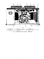
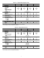
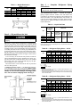
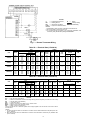
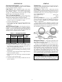
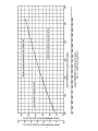
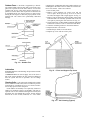
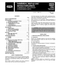
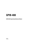
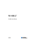
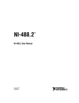
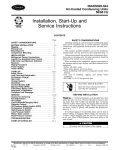
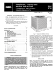
38AE012,014,016
38AKS024
Air-Cooled Condensing Units
50/60 Hz
Installation, Start-Up and
Service Instructions
CONTENTS
Page
SAFETY CONSIDERATIONS . . . . . . . . . . . . . . . . . . . 1
INSTALLATION . . . . . . . . . . . . . . . . . . . . . . . . . . . . . . 1-8
Step 1 — Complete Pre-Installation Checks . . . . 1
Step 2 — Rig and Mount the Unit . . . . . . . . . . . . . 6
Step 3 — Complete Refrigerant Piping
Connections . . . . . . . . . . . . . . . . . . . . . . . . . . . . . . . . . 6
Step 4 — Install Accessories . . . . . . . . . . . . . . . . . 7
Step 5 — Complete Electrical Connections . . . . 7
PRE-START-UP . . . . . . . . . . . . . . . . . . . . . . . . . . . . . . 9
Evacuate and Dehydrate . . . . . . . . . . . . . . . . . . . . . . 9
Leak Test . . . . . . . . . . . . . . . . . . . . . . . . . . . . . . . . . . . . 9
Turn On Crankcase Heaters . . . . . . . . . . . . . . . . . . 9
Add Preliminary Charge . . . . . . . . . . . . . . . . . . . . . . 9
Before Starting Unit . . . . . . . . . . . . . . . . . . . . . . . . . . 9
START-UP . . . . . . . . . . . . . . . . . . . . . . . . . . . . . . . . . 9-13
To Start Unit . . . . . . . . . . . . . . . . . . . . . . . . . . . . . . . . . 9
Oil Charge . . . . . . . . . . . . . . . . . . . . . . . . . . . . . . . . . . . 9
Refrigerant Charge . . . . . . . . . . . . . . . . . . . . . . . . . . . 9
Check Operation . . . . . . . . . . . . . . . . . . . . . . . . . . . . 13
OPERATING SEQUENCE . . . . . . . . . . . . . . . . . . . . 13
Cooling . . . . . . . . . . . . . . . . . . . . . . . . . . . . . . . . . . . . . 13
Heating . . . . . . . . . . . . . . . . . . . . . . . . . . . . . . . . . . . . . 13
Fan Cycling . . . . . . . . . . . . . . . . . . . . . . . . . . . . . . . . . 13
Winter Start Control . . . . . . . . . . . . . . . . . . . . . . . . . 13
SERVICE . . . . . . . . . . . . . . . . . . . . . . . . . . . . . . . . . . 13,14
Capacity Control . . . . . . . . . . . . . . . . . . . . . . . . . . . . 13
Head Pressure Control . . . . . . . . . . . . . . . . . . . . . . 13
Time GuardT II Circuit . . . . . . . . . . . . . . . . . . . . . . . 13
Winter Start Control . . . . . . . . . . . . . . . . . . . . . . . . . 13
Crankcase Heater . . . . . . . . . . . . . . . . . . . . . . . . . . . 13
Outdoor Fan . . . . . . . . . . . . . . . . . . . . . . . . . . . . . . . . 14
Lubrication . . . . . . . . . . . . . . . . . . . . . . . . . . . . . . . . . 14
Cleaning Coils . . . . . . . . . . . . . . . . . . . . . . . . . . . . . . 14
TROUBLESHOOTING . . . . . . . . . . . . . . . . . . . . . . 15,16
START-UP CHECKLIST . . . . . . . . . . . . . . . . CL-1,CL-2
SAFETY CONSIDERATIONS
Installing, starting up, and servicing air-conditioning equipment can be hazardous due to system pressures, electrical
components, and equipment location (roofs, elevated structures, etc.).
Only trained, qualified installers and service mechanics
should install, start-up, and service this equipment (Fig. 1).
Untrained personnel can perform basic maintenance functions such as cleaning coils. All other operations should be
performed by trained service personnel.
When working on the equipment, observe precautions in
the literature and on tags, stickers, and labels attached to the
equipment.
Follow all safety codes. Wear safety glasses and work gloves.
Keep quenching cloth and fire extinguisher nearby when
brazing. Use care in handling, rigging and setting bulky
equipment.
ELECTRIC SHOCK HAZARD
Separate power sources (main and control
power circuits) are used for these units. Be
sure both main and control power circuits are
disconnected before servicing.
INSTALLATION
Step 1 — Complete Pre-Installation Checks
UNCRATE UNIT — Remove unit packaging except for the
top skid assembly, which should be left in place until after
the unit is rigged into its final location.
INSPECT SHIPMENT — File claim with shipping company if shipment is damaged or incomplete.
CONSIDER SYSTEM REQUIREMENTS
• Consult local building codes and National Electrical Code
(NEC, U.S.A.) for special installation requirements.
• Allow sufficient space for airflow clearance, wiring, refrigerant piping, and servicing unit. See Fig. 1. See
Fig. 2 for unit component locations.
• Locate unit so that outdoor coil (condenser) airflow is unrestricted on all sides and above.
• Unit may be mounted on a level pad directly on the base
channels or mounted on raised pads at support points. See
Table 1A-1D for unit operating weights. See Table 2 for
weight distribution based on recommended support points.
NOTE: If vibration isolators are required for a particular
installation, use the data in Table 2 to make the proper
selection.
Manufacturer reserves the right to discontinue, or change at any time, specifications or designs without notice and without incurring obligations.
Book 1 4
PC 111
Catalog No. 563-746
Printed in U.S.A.
Form 38A-4SI
Pg 1
4-94
Replaces: 38AE-17SI
Tab 3a 2a
LEGEND
A — 11⁄4-in. (32) diameter knockout for 5⁄8-in. (16) ODM liquid line connection
B — 13⁄4-in. (44.5) diameter knockout for suction line connections of 11⁄8 in. (28.6)
(38AE012), 13⁄8 in. (35) (38AE014,016), 15⁄8 in. (41) (38AKS024)
C — 7⁄8-in. (22.2) diameter knockout for control power
D — 2-in. (50.8) diameter knockout for unit power
NOTES:
1. SERVICE AREAS — Allow 3 ft (914) on both sides
and 2 ft (610) on both ends of unit for servicing.
2. Dimensions in ( ) are in millimeters.
Certified dimension drawings are available on request.
Fig. 1 — Dimensions (ft-in.)
2
2
1
12
3
4
11
5
10
6
9
7
8
LEGEND
1
2
3
4
—
—
—
—
Low-Voltage Fuse
No. 1 Fan
High-Pressure Switch
Circuit Breakers
5
6
7
8
—
—
—
—
No. 2 Fan
Terminal Block 1 (Unit Power)
Terminal Block 2 (Control Power)
Wraparound Coil
9
10
11
12
—
—
—
—
Compressor
Low-Pressure Switch
Hot Gas Bypass Piping Stub (3⁄8-in. ODM)
Muffler
Fig. 2 — Component Locations (Typical — 38AE Shown)
3
Table 1A — Physical Data (English, 60 Hz)
UNIT
OPERATING WEIGHT (lb)
REFRIGERANT*
COMPRESSOR
Speed (Rpm)
No. Cylinders
Model No.
Oil (pt)
Crankcase Heater Watts
Unloader Setting (psig)
Load
Unload
OUTDOOR-AIR FANS
No. ...Rpm
Diameter (in.)
Motor Hp
Nominal Total Airflow (Cfm)
OUTDOOR COIL
Face Area (sq ft)
Storage Capacity (lb)†
CONTROLS
Pressurestat Settings (psig)
High Cutout
Cut-in
Low Cutout
Cut-in.
FUSIBLE PLUG (F)
PIPING CONNECTIONS (in. ODM)
Suction
Liquid
38AE012
732
38AE014
779
38AE016
789
6
06DD824
10
125
R-22
Reciprocating, Semi-Hermetic
1750
6
6
06DD328
06DD537
10
10
125
125
8800
70 ± 1
60 ± 2
Axial Flow, Direct Drive
2...1075
24
24
1 ⁄2
8800
8800
27.2
40.3
24
38AKS024
900
4
06E4250
15.5
180
26
11,000
29.2
39.8
39.8
1 3 ⁄8
15⁄8
38AE016
359
38AKS024
408
395 ± 10
295 ± 10
29 ± 4
60 +15, –0
200
11⁄8
13⁄8
⁄
58
Unit is factory supplied with holding charge only.
†Storage capacity is measured at liquid saturated temperatures of 125 F for 38AE012,
123 F for 38AE014, and 130 F for 38AE016 and 38AKS024.
Table 1B — Physical Data (SI, 60 Hz)
UNIT
OPERATING WEIGHT (kg)
REFRIGERANT*
COMPRESSOR
Speed (r/s)
No. Cylinders
Model No.
Oil (L)
Crankcase Heater Watts
Unloader Setting (kPa)
Load
Unload
OUTDOOR-AIR FANS
No. ...r/s
Diameter (mm)
Motor Hp
Nominal Total Airflow (L/s)
OUTDOOR COIL
Face Area (sq m)
Storage Capacity (kg)†
CONTROLS
Pressurestat Settings (kPa)
High Cutout
Cut-in
Low Cutout
Cut-in
FUSIBLE PLUG (C)
PIPING CONNECTIONS (in. ODM)
Suction
Liquid
38AE012
333
38AE014
354
6
06DD824
4.73
125
R-22
Reciprocating, Semi-Hermetic
29.2
6
6
06DD328
06DD537
4.73
4.73
125
125
4153
483 ± 6.9
414 + 103, –0
Axial Flow, Direct Drive
2...17.9
610
610
1 ⁄2
4153
4153
12.4
18.3
610
4
06E4250
7.33
180
661
5566
2.71
18.1
18.1
1 3 ⁄8
15⁄8
2724 ± 68.9
2034 ± 68.9
200 ± 27.6
414 + 103, –0
93.3
11⁄8
13⁄8
⁄
58
*Unit is factory supplied with holding charge only.
†Storage capacity is measured at liquid saturated temperatures of 51.7 C for 38AE012,
50.6 C for 38AE014, and 54.4 C for 38AE016 and 38AKS024.
4
Table 1C — Physical Data (English, 50 Hz)
UNIT
OPERATING WEIGHT (lb)
REFRIGERANT*
COMPRESSOR
Speed (Rpm)
No. Cylinders
Model No.
Oil (pt)
Crankcase Heater Watts
Unloader Setting (psig)
Load
Unload
OUTDOOR-AIR FANS
No. ...Rpm
Diameter (in.)
Motor Hp
Nominal Total Airflow (Cfm)
OUTDOOR COIL
Face Area (sq ft)
Storage Capacity (lb)†
CONTROLS
Pressurestat Settings (psig)
High Cutout
Cut-in
Low Cutout
Cut-in
FUSIBLE PLUG (F)
PIPING CONNECTIONS (in. ODM)
Suction
Liquid
38AE012
732
38AE014
779
38AE016
789
6
06DD824
10
125
R-22
Reciprocating, Semi-Hermetic
1460
6
6
06DD328
06DD537
10
10
125
125
7368
70 ± 1
60 ± 2
Axial Flow, Direct Drive
2...900
24
24
1 ⁄2
7368
7368
27.2
40.3
24
38AKS024
900
4
06E4250
15.5
180
26
9210
29.2
39.8
39.8
1 3 ⁄8
15⁄8
38AE016
359
38AKS024
408
395 ± 10
295 ± 10
29 ± 4
60 + 15, –0
200
11⁄8
13⁄8
⁄
58
*Unit is factory supplied with holding charge only.
†Storage capacity is measured at liquid saturated temperatures of 125 F for 38AE012,
123 F for 38AE014, and 130 F for 38AE016 and 38AKS024.
Table 1D — Physical Data (SI, 50 Hz)
UNIT
OPERATING WEIGHT (kg)
REFRIGERANT*
COMPRESSOR
Speed (r/s)
No. Cylinders
Model No.
Oil (L)
Crankcase Heater Watts
Unloader Setting (kPa)
Load
Unload
OUTDOOR-AIR FANS
No. ...r/s
Diameter (mm)
Motor Hp
Nominal Total Airflow (L/s)
OUTDOOR COIL
Face Area (sq m)
Storage Capacity (kg)†
CONTROLS
Pressurestat Settings (kPa)
High Cutout
Cut-in
Low Cutout
Cut-in
FUSIBLE PLUG (C)
PIPING CONNECTIONS (in. ODM)
Suction
Liquid
38AE012
333
38AE014
354
6
06DD824
4.73
125
R-22
Reciprocating, Semi-Hermetic
24.3
6
6
06DD328
06DD537
4.73
4.73
125
125
3728
483 ± 6.9
414 + 103, –0
Axial Flow, Direct Drive
2...15.0
610
610
1 ⁄2
3728
3728
12.4
18.3
610
4
06E4250
7.33
180
661
4660
2.71
18.1
18.1
1 3 ⁄8
15⁄8
2724 ± 68.9
2034 ± 68.9
200 ± 27.6
414 + 103, –0
93.3
11⁄8
13⁄8
⁄
58
*Unit is factory supplied with holding charge only.
†Storage capacity is measured at liquid saturated temperatures of 51.7 C for 38AE012,
50.6 C for 38AE014, and 54.4 C for 38AE016 and 38AKS024.
5
Table 2 — Weight Distribution
UNIT
38AE012
38AE014
38AE016
38AKS024
Total
Operating
732
779
789
900
(333)
(354)
(359)
(408)
WEIGHT — lb (kg)
Support Point
A
B
C
142 (65) 138 (63) 225 (102)
143 (65) 140 (64) 247 (112)
143 (65) 143 (65) 250 (114)
178 (81) 168 (76) 269 (122)
Step 3 — Complete
Connections
Refrigerant
Piping
IMPORTANT: A refrigerant receiver is not provided
with the unit. Do not install a receiver.
D
227(103)
249 (113)
253 (115)
285 (129)
SIZE REFRIGERANT LINES — Consider the length of
piping required between outdoor unit and indoor unit
(evaporator), the amount of liquid lift, and compressor oil
return. See Tables 3, 4A, and 4B and also refer to Part 3 of
Carrier System Design Manual for design details and line
sizing. Refer to indoor installation instructions for additional information.
Table 3 — Liquid Line Data
MAXIMUM
ALLOWABLE
LIQUID LIFT
ft (m)
UNIT
60 Hz
Step 2 — Rig and Mount the Unit
50 Hz
38AE012
52 (15.8)
38AE014
67 (20.4)
38AE016
82 (25)
38AKS024 87 (26.5) 86 (26)
Be sure unit panels are securely in place prior to
rigging.
LIQUID LINE
Maximum Filter Drier
Maximum
Allowable
and
Allowable
Temp.
Sight Glass
Pressure Drop
Loss
Flare Conn.*
psig (kPa)
F (C)
in. (mm)
7 (48.3)
2 (1.1)
⁄
58
*Inlet and outlet.
NOTE: Data shown is for units operating at 45 F (7.2 C) saturated suction and
95 F (35 C) entering air.
RIGGING — These units are designed for overhead rigging
only. For this purpose, the transverse base channels extend
beyond the sides of the unit, with holes provided in the end
plates to attach cables or hooks. Rig with top skid packaging
assembly in place to prevent unit damage by the rigging cable.
As further protection for the coil faces, plywood sheets can
be placed against the sides of the unit, behind the cables.
Run the cables to a central suspension point so that the angle
from the horizontal is not less than 45 degrees. Raise and set
the unit down carefully.
If it is necessary to roll the unit into position, mount the
unit on longitudinal rails, using a minimum of 3 rollers. Apply force to the rails, not the unit. If the unit is to be skidded
into position, place it on a large pad and drag it by the pad.
Do not apply any force to the unit.
Raise from above to lift unit from the rails or pad when
unit is in final position.
COMPRESSOR MOUNTING — As shipped, the compressor is held tightly in place by self-locking bolts. Before starting unit, loosen self-locking bolts until the snubber
washer can be moved sideways with finger pressure. Do not remove shipping bolts. See Fig. 3.
Table 4A — Refrigerant Piping Sizes — 60 Hz
UNIT
38AE012
38AE014
38AE016
38AKS024
LENGTH OF INTERCONNECTING PIPING — FT (M)
0-15
15-25
25-50
50-75
75-100
(0-4.6)
(4.6-7.6) (7.6-15.2) (15.2-22.9) (22.9-30.5)
Line Size — in. OD
L
S
L
S
L
S
L
S
L
S
5 ⁄8
5⁄8
5⁄8
1⁄2
11⁄8 1⁄2 11⁄8
13⁄8
13⁄8
15⁄8
5 ⁄8
5⁄8
7⁄8
1⁄2
11⁄8 1⁄2 13⁄8
13⁄8
15⁄8
15⁄8
5 ⁄8
7⁄8
7⁄8
1⁄2
13⁄8 5⁄8 13⁄8
15⁄8
15⁄8
21⁄8
7 ⁄8
7⁄8
7⁄8
5⁄8
15⁄8 5⁄8 15⁄8
15⁄8
21⁄8
21⁄8
LEGEND
L — Liquid
S — Suction
Close coupled.
NOTES:
1. Pipe sizes are based on a 2 F (1.1 C) loss for liquid lines and a 1.5 F
(0.8 C) loss for suction lines.
2. Pipe sizes are based on an equivalent length equal to the maximum length
of interconnecting piping plus 50% for fittings. A more accurate estimate may
result in smaller sizes.
Table 4B — Refrigerant Piping Sizes — 50 Hz
UNIT
38AE012
38AE014
38AE016
38AKS024
LENGTH OF INTERCONNECTING PIPING — FT (M)
0-15
15-25
25-50
50-75
75-100
(0-4.6)
(4.6-7.6) (7.6-15.2) (15.2-22.9) (22.9-30.5)
Line Size — in. OD
L
S
L
S
L
S
L
S
L
S
5 ⁄8
5⁄8
5⁄8
1⁄2
11⁄8 1⁄2 11⁄8
11⁄8
13⁄8
13⁄8
5 ⁄8
5⁄8
5⁄8
1⁄2
11⁄8 1⁄2 11⁄8
13⁄8
13⁄8
13⁄8
5 ⁄8
5⁄8
5⁄8
1⁄2
13⁄8 5⁄8 13⁄8
13⁄8
13⁄8
15⁄8
5 ⁄8
7⁄8
7⁄8
5⁄8
15⁄8 5⁄8 15⁄8
15⁄8
15⁄8
15⁄8
LEGEND
L — Liquid
S — Suction
Close coupled.
NOTES:
1. Pipe sizes are based on a 2 F (1.1 C) loss for liquid lines and a 1.5 F
(0.8 C) loss for suction lines.
2. Pipe sizes are based on an equivalent length equal to the maximum length
of interconnecting piping plus 50% for fittings. A more accurate estimate may
result in smaller sizes.
Fig. 3 — Compressor Mounting
6
INSTALL FILTER DRIER(S) AND MOISTURE INDICATOR(S) — Every unit should have a filter drier and liquidmoisture indicator (sight glass). In some applications, depending
on space and convenience requirements, it may be desirable
to install 2 filter driers and sight glasses. One filter drier and
sight glass may be installed at A locations in Fig. 4. Or, 2
filter driers and sight glasses may be installed at B locations.
Select the filter drier for maximum unit capacity and minimum pressure drop. Complete the refrigerant piping from
indoor unit to outdoor unit before opening the liquid and suction lines at the outdoor unit.
NOTE: 38AKS024 has a fusible plug in the liquid line.
Fig. 5 — Location of Fusible Plug (38AE)
Step 4 — Install Accessories — Field install accessories such as winter start control or low-ambient control
before proceeding with wiring. Refer to the instructions shipped
with the accessory.
Step 5 — Complete Electrical Connections
POWER WIRING — Unit is factory wired for voltage shown
on nameplate. Provide adequate fused disconnect switch within
sight from unit and readily accessible from unit, but out of
the reach of children. Lock switch open (off) to prevent power
from being turned on while unit is being serviced. Disconnect switch, fuses, and field wiring must comply with national and local code requirements. See Tables 5A and 5B.
Route power wires through opening in unit end panel to
connection in unit control box as shown on unit label diagram and in Fig. 6. Unit must be grounded.
Affix crankcase heater warning sticker to unit disconnect
switch.
CONTROL CIRCUIT WIRING — Control voltage is 24 v.
See Fig. 7 and unit label diagram for field-supplied wiring
details. Route control wires through opening in unit end panel
to connection in unit control box.
TXV — Thermal Expansion Valve
Fig. 4 — Location of Sight Glass(es)
and Filter Drier(s)
INSTALL LIQUID LINE SOLENOID VALVE — SOLENOID DROP — It is recommended that a solenoid valve be
placed in the main liquid line (see Fig. 4) between condensing unit (38AE/AKS) and fan coil (40RR, 40RE). (A liquid
line solenoid valve is required when the liquid line length
exceeds 100 ft [30.5 m] or when the condensing unit is connected to the chiller barrel in a built-up chiller system.) This
valve prevents refrigerant migration (which causes oil dilution) to the compressor during the off cycle at low outdoor
ambient temperatures. The solenoid should be wired in parallel with the compressor contactor coil. This means of electrical control is referred to as solenoid drop control.
INSTALL LIQUID LINE SOLENOID VALVE (OPTIONAL)
— CAPACITY CONTROL — If 2-step cooling is desired,
place a solenoid valve in the location shown in Fig. 4.
MAKE PIPING CONNECTIONS — Do not remove runaround loop from suction and liquid line stubs in the compressor compartment until piping connections are ready to
be made. Pass nitrogen or other inert gas through piping while
brazing to prevent formation of copper oxide.
Install field-supplied thermostatic expansion valve(s) in indoor section. If 2 thermostatic expansion valves are installed
for 2-step cooling, install field-supplied liquid line solenoid
valve ahead of the second expansion valve.
PROVIDE SAFETY RELIEF — A fusible plug is located
on the compressor crankcase or in the liquid line (Fig. 5).
Do not cap this plug. If local code requires additional safety
devices, install them as directed.
LEGEND
EQUIP GND — Equipment Ground
NEC
— National Electrical Code
Factory Wiring
Field Wiring
Fig. 6 — Main Power Supply Wiring
7
LEGEND
C
— Compressor Contactor
R — Relay
HD
— Heating Device
Factory Wiring
IFC
— Indoor-Fan Contactor
Field Wiring
LLSV — Liquid Line Solenoid Valve
NOTES:
1. Combination LLSV plus IFC va should not exceed 30 va.
2. Do not exceed 5 va (24 vac) per coil.
3. If va values shown in Notes 1 and 2 must be exceeded, use
accessory relay transformer package 38AE900001.
Fig. 7 — Remote Thermostat Wiring
Table 5A — Electrical Data (3 Ph/60 Hz)
UNIT
UNIT
38AE012
38AE014
38AE016
38AKS024
COMPR
FAN MOTORS (Single Phase)
Volts
Model
501
201
601
101
501
201
601
101
501
201
601
101
501
201
601
101
Supplied*
Min
Max
187
253
342
418
414
528
518
660
187
253
342
418
414
528
518
660
187
253
342
418
414
528
518
660
187
254
342
418
414
508
518
632
Nameplate
208-230
380
460
575
208-230
380
460
575
208-230
380
460
575
208-230
380
460
575
MCA
62.5
35.0
29.1
22.8
69.3
38.0
31.7
25.6
87.5
49.3
40.7
33.0
93.4
49.7
48.1
40.1
ICF
178
101
81
67
199
112
84
73
274
153
124
100
353
199
177
124
MOCP
(Fuse)
100
50
40
35
100
60
50
40
125
80
60
50
150
80
80
60
RLA
43.6
24.0
20.0
15.7
49.3
26.5
22.1
17.9
63.6
36.0
29.3
23.8
67.9
34.6
34.7
28.8
FLA (ea)
Fan No.
Total
Fans
LRA
170
93
77
62
191
104
80
69
266
145
120
96
345
191
173
120
1
4.3
4.3
2.3
1.8
4.3
4.3
2.3
1.8
4.3
4.3
2.3
1.8
4.3
4.3
2.3
1.8
2
2
2
2
2
3.7
3.7
1.9
1.8
3.7
3.7
1.9
1.8
3.7
3.7
1.9
1.8
3.7
3.7
1.9
1.8
kW
1.41
1.41
1.41
1.41
Table 5B — Electrical Data (3 Ph/50 Hz)
UNIT
UNIT
38AE012
38AE014
38AE016
38AKS024
COMPR
FAN MOTORS 230 v (Single Phase)
Volts
Model
803
903
803
903
803
903
803
303
903
Nameplate
230
400
230
400
230
400
230
346
400
Supplied*
Min
Max
198
264
342
457
198
264
342
457
198
264
342
457
198
254
311
380
342
440
MCA
47.5
31.4
51.0
34.0
66.9
43.0
91.8
51.5
50.2
MOCP
(Fuse)
ICF
134
80
149
89
206
121
213
121
179
75
50
75
50
100
60
150
80
80
RLA
32.9
20.0
35.7
22.1
47.9
29.3
67.9
33.3
34.6
LRA
128
74
143
83
200
115
207
115
173
LEGEND
FLA — Full Load Amps (Fan Motors)
ICF
— Maximum Instantaneous Current Flow during start-up (LRA of compressor plus total FLA of fan motors)
kW
— Total Fan Motor Input (kilowatts)
LRA — Locked Rotor Amps
MCA — Minimum Circuit Amps per NEC (U.S.A.), Section 430-24
MOCP — Maximum Overcurrent Protection (amps)
RLA — Rated Load Amps (Compressor)
*Units are suitable for use on electrical systems where voltage supplied to the unit terminals is not below or above
the listed limits.
NOTES:
1. The MCA and MOCP values are calculated in accordance with the National Electrical Code (NEC) article 440
(U.S.A. standard).
2. Motor RLA and LRA values are established in accordance with Underwriters’ Laboratories (UL) Standard 1995
(U.S.A. standard).
8
FLA (ea)
Fan No.
Total
Fans
kW
1
2
2
2.9
3.5
1.20
2
2.9
3.5
1.20
2
2.9
3.5
1.20
2
2.9
3.5
1.20
PRE-START-UP
START-UP
Evacuate and Dehydrate the entire refrigerant sys-
To Start Unit — Set thermostat set point below the space
temperature. After starting unit, there is a delay of at least 3
seconds before compressor starts.
tem by either of the methods described in Carrier Standard
Service Techniques Manual, Chapter 1.
Leak Test the entire refrigerant system by the pres-
Oil Charge (see Tables 1A-1D) —Allow unit to run for
about 20 minutes. Stop unit and check compressor oil level
at sight glass. Add oil if necessary to bring oil to the correct
level shown in Fig. 8. Use only Carrier-approved compressor oil. Approved oils are:
Witco Chemical Corp. . . . . . . . . . . . . . . . . Suniso 3GS
Texaco, Inc. . . . . . . . . . . . . . . . . . . . . . . . . . . . WF32
Petroleum Specialties Co. . . . . . . . . . . . . . . . Cryol 150
Do not reuse drained oil or use any oil that has been exposed to atmosphere. Procedures for adding or removing oil
are given in Carrier Standard Service Techniques Manual,
Chapter 1, Refrigerants.
If oil is added, run unit for additional 10 minutes. Stop
unit and check oil level. If level is still low, add oil only after
determining that piping system is designed for proper oil return and that the system is not leaking oil.
sure method described in Carrier Standard Service Techniques Manual, Chapter 1. Use R-22 at approximately
25 psig (172.4 kPa) backed up with an inert gas to a total
pressure not to exceed 245 psig (1689 kPa).
Turn on Crankcase Heaters for 24 hours before starting the unit to be sure all the refrigerant is out of the oil. To
energize the crankcase heaters, proceed as follows.
1. Set the space thermostat set point above the space temperature so there is no demand for cooling.
2. Close the field disconnect.
3. Turn the fan circuit breaker on. Leave the compressor circuit breakers off. The crankcase heaters are now
energized.
Add Preliminary Charge to the refrigerant system accordingly to Carrier Standard Service Techniques Manual,
Chapter 1. By the liquid charging method and charging by
weight procedure, charge the units with approximately the
amounts of R-22 refrigerant shown in Table 6.
Table 6 — Charging Data (R-22)
UNIT
38AE012
38AE014
38AE016
38AKS024
REFRIGERANT CHARGE - lb (kg)
Required Charge
Outdoor Unit
Above Clear
Total Charge
Sight Glass
(Approx)
3.0 (1.4)
22 (10)
4.8 (2.2)
23 (10.5)
3.4 (1.5)
23 (10.5)
3.4 (1.5)
28 (12.7)
CONDENSING
TEMP
DURING
CHARGING - F (C)
125
123
130
131
38AKS024
(06E COMPRESSOR)
(51.7)
(50.6)
(54.4)
(54.8)
38AE012,014,016
(06D COMPRESSOR)
Fig. 8 — Operating Oil Levels
Refrigerant Charge — Actual start-up should be done
only under supervision of a qualified refrigeration mechanic. Refer to charging charts.
See Fig. 9-11 for the particular unit being charged. Measure pressure at the liquid line service valve, being sure a
Schrader depressor is used if required. Also, measure liquid
line temperature as close to the liquid service valve as possible. Add or reduce charge until the pressure and temperature conditions of the charging charge curve are met. If liquid pressure and temperature point falls above curve, add
charge. If liquid pressure and temperature point falls below
curve, reduce the charge until the conditions match the curve.
Before Starting Unit ensure the following:
1. Compressor oil level must be at least within sight in
the compressor sight glass. Add oil if necessary (see
Tables 1A-1D and Oil Charge section).
2. Compressor holddown bolts must be snug, but not tight.
Refer to Compressor Mounting section and tag on compressor foot.
3. All internal wiring connections must be tight; all barriers
and covers must be in place.
4. Electrical power source must agree with unit nameplate
rating.
5. All service valves must be open.
6. Crankcase heater must be firmly locked into the compressor crankcase.
Never charge liquid into the low-pressure side of system. Do not overcharge. During charging or removal of
refrigerant, be sure indoor fan system is operating.
9
10
Fig. 9 — 38AE012 and 38AKS024 Charging Chart
11
Fig. 10 — 38AE014 Charging Chart
12
Fig. 11 — 38AE016 Charging Chart
Check Operation — Verify operation of all safety controls. Replace all service panels. Be sure that control panel
cover is closed tightly.
Head Pressure Control — Fan cycling is a standard
feature. The no. 2 fan cycles in response to changes in liquid
pressure. The switch cycles the fan off at 126 ± 4 psig (869
± 28 kPa) as pressure decreases, and cycles it back on at 257
(+5, −0) psig (1772 [+103, −0] kPa).
OPERATING SEQUENCE
Cooling — When the first stage (TC1) of the cooling thermostat closes, the timer starts. After approximately 3 seconds, the timer activates the compressor and fan motor no.
1 contactor. When the liquid pressure builds to approximately 257 psig (1772 kPa), fan motor no. 2 is energized.
On demand for additional cooling capacity, the second stage
(TC2) of the cooling thermostat closes, energizing a fieldsupplied liquid line solenoid (LLS) valve, which opens. This
increases the suction pressure, causing the compressor to operate at higher capacity.
When fan switch is set at AUTO, the indoor-air fan cycles
with the compressor. When the switch is set at CONT, the
indoor-air fan runs continuously.
At shutdown, the Time Guardt II timer prevents the compressor from restarting for approximately 5 minutes.
When installed, a field-supplied solenoid valve (wired in
parallel with the compressor contactor coil), shuts off the liquid line to prevent refrigerant migration back to the compressor during the off cycle.
Heating — The heating thermostat (TH) energizes a fieldsupplied relay which operates heating controls and energizes the indoor-fan relay. When the fan switch is set at AUTO,
the indoor-air fan cycles with the heating control. The indoorair fan runs continuously when the fan switch is set at CONT.
Fig. 12 — Compressor Capacity Control Unloader
Fan Cycling — Head pressure control is accomplished
Time Guard II Circuit — Prevents short-cycling by providing a delay of approximately 5 minutes before restarting
compressor after shutdown from safety device action.
On start-up, the Time Guard II timer causes a delay of
approximately 3 seconds after thermostat closes.
On compressor shutdown, the timer recycles for approximately 5 minutes. During this time, the compressor cannot
restart.
Refer to Fig. 13 and to label diagram on unit.
by cycling the fans. The no. 2 fan responds to liquid line
pressure, cycling on at approximately 257 psig (1772 kPa)
and off at approximately 126 psig (869 kPa).
Winter Start Control (If Installed) — When the compressor starts, the control’s bypass timer contacts close for
150 seconds, thereby bypassing the low-pressure switch during start-up. After 150 seconds, the bypass timer contacts
open and the low-pressure switch is restored to the safety
circuit.
SERVICE
Capacity Control — A suction pressure-actuated unloader controls 2 cylinders and provides capacity control. Unloaders are factory set (see Tables 1A-1D), but can be field
adjusted as described in the 2 following sections.
CONTROL SET POINT (cylinder load point) is adjustable
from 0 to 85 psig (586 kPa). To adjust, turn control set point
adjustment nut (Fig. 12) clockwise to its bottom stop. In this
position, set point is 85 psig (586 kPa). Next, turn adjustment counterclockwise to desired control set point. Every
full turn counterclockwise decreases set point by
7.5 psig (51.7 kPa).
PRESSURE DIFFERENTIAL (difference between cylinder
load and unload points) is adjustable from 6 to 22 psig (41.4
to 152 kPa). To adjust, turn pressure differential adjustment
screw (Fig. 12) counterclockwise to its back stop position.
In this position, differential is 6 psig (41.4 kPa). Next, turn
adjustment clockwise to desired pressure differential setting.
Every full turn clockwise increases differential by 1.5 psig
(10.3 kPa).
Fig. 13 — Timer Sequence Chart
Winter-Start Control (If Required) — Install Accessory Package 38AE900021.
Crankcase Heater — The heater prevents refrigerant
migration and compressor oil dilution during shutdown whenever compressor is not operating. It is wired into the control
circuit, and cycles with the compressor; the heater is off when
compressor is running, and on when compressor is off.
Both compressor service valves must be closed whenever
the crankcase heater is deenergized for more than 6 hours.
The crankcase heater is operable as long as the control circuit is energized.
13
(38AE014,016, 38AKS024) and restrict outdoor airflow. Use
a flashlight to determine if dirt or debris has collected between coil sections. Clean coil as follows:
1. Turn off unit power.
2. Remove screws holding rear corner posts and top
cover in place. Pivot top cover up 12 to 18 in. (305 to
457 mm) and support with a rigid support. See Fig. 15.
3. Remove clips securing tube sheets together at the return
bend end of the coil. Carefully spread the ends of the coil
rows apart by moving the outer sections. See Fig. 16.
4. Using a water hose, or other suitable equipment, flush down
between the sections of coil to remove dirt and debris.
5. Clean the remaining surfaces in the normal manner.
6. Reposition outer coil sections.
7. Reinstall clips which secure tube sheets.
8. Replace top cover and rear corner posts.
Outdoor Fans — Each fan is supported by a formedwire mount bolted to the fan deck and covered with a wire
guard. The exposed end of the motor shaft is covered with
a rubber boot. In case a fan motor must be repaired or replaced, be sure the rubber boot is put back on when the fan
is reinstalled and be sure the fan guard is in place before
starting the unit. Figure 14 shows the proper position of the
mounted fan. Fan motors have permanently lubricated
bearings.
38AE012,014,016
38AKS024
Fig. 14 — Outdoor Fan
Lubrication
Fig. 15 — Pivot and Support Top Cover
FAN MOTORS have sealed bearings. No provisions are made
for lubrication.
COMPRESSOR has its own oil supply. Loss of oil due to a
leak in the system should be the only reason for adding oil
after the system has been in operation. See Oil Charge
section.
Cleaning Coils — The coils can be cleaned with a vacuum
cleaner, washed out with water, blown out with low-pressure
compressed air, or brushed (do not use wire brush). Fan motors are drip-proof but not waterproof.
Clean outdoor coil annually or as required by location or
outdoor air conditions. Inspect coil monthly, and clean as
required. Fins are not continuous through coil sections; dirt
and debris may pass through first section, become trapped
between the 2 rows of fins (38AE012) or 3 rows of fins
Fig. 16 — Coil Cleaning (Typical)
14
TROUBLESHOOTING
PROBLEM
COMPRESSOR DOES NOT RUN
Contactor Open
1. Power off.
2. Fuses blown in field power circuit.
3. No control power.
4. Thermostat circuit open.
5. Time GuardT II device not operating.
6. Compressor circuit breaker tripped.
7. Safety device lock-out circuit active.
8. Low-pressure switch open.
9. High-pressure switch open.
10. Compressor overtemperature switch open.
11. Loose electrical connections.
12. Compressor stuck.
SOLUTION
1. Restore power.
2. After finding cause and correcting, replace with correct size fuse.
3. Check secondary fuse(s); replace with correct type and size.
Replace transformer if primary windings receiving power.
4. Check thermostat setting.
5. Check Time Guard II devices.
6. Check for excessive compressor current draw. Reset breaker;
replace if defective.
7. Reset lock-out circuit at thermostat or circuit breaker.
8. Check for refrigerant undercharge, obstruction of indoor airflow, or
whether compressor suction shutoff valve is fully open. Make sure liquid
line solenoid valve(s) is open.
9. Check for refrigerant overcharge, obstruction of outdoor airflow, air in
system, or whether compressor discharge valve is fully open. Be sure
outdoor fans are operating correctly.
10. Check for open condition. Allow for reset. Replace if defective.
11. Tighten all connections.
12. See compressor service literature.
Contactor Closed
1. Compressor leads loose.
2. Motor windings open.
3. Single phasing.
COMPRESSOR STOPS ON HIGH-PRESSURE SWITCH
1. Check connections.
2. See compressor service literature.
3. Check for blown fuse. Check for loose connection at compressor terminal.
Outdoor Fan On
1.
2.
3.
4.
5.
6.
7.
8.
High-pressure switch faulty.
Reversed fan rotation.
Airflow restricted.
Air recirculating.
Noncondensables in system.
Refrigerant overcharge.
Line voltage incorrect.
Refrigerant system restrictions.
1.
2.
3.
4.
5.
6.
7.
8.
Replace switch.
Confirm rotation, correct if necessary.
Remove obstruction.
Clear airflow area.
Purge and recharge as required.
Purge as required.
Consult power company.
Check or replace filter drier, expansion valve, etc. Check that compressor
discharge service valve is fully open.
1.
2.
3.
4.
5.
Tighten fan hub setscrews.
Check power and capacitor.
Replace bearings.
Check overload rating. Check for fan blade obstruction.
Replace motor.
Outdoor Fan Off
1. Fan slips on shaft.
2. Motor not running.
3. Motor bearings stuck.
4. Motor overload open.
5. Motor burned out.
COMPRESSOR CYCLES ON LOW-PRESSURE SWITCH
Indoor-Air Fan Running
1. Compressor suction service valve partially
closed.
2. Liquid line solenoid valve(s) fails to open.
3. Filter drier plugged.
4. Expansion valve power head defective.
5. Low refrigerant charge.
1. Open valve fully.
2. Check liquid line solenoid valve(s) for proper operation. Replace if
necessary.
3. Replace filter drier.
4. Replace power head.
5. Add charge. Check low-pressure switch setting.
15
TROUBLESHOOTING (cont)
PROBLEM
COMPRESSOR CYCLES ON LOW-PRESSURE SWITCH (cont)
SOLUTION
Airflow Restricted
1.
2.
3.
4.
Coil iced up.
Coil dirty.
Air filters dirty.
Dampers closed.
1.
2.
3.
4.
Check refrigerant charge.
Clean coil fins.
Clean or replace filters.
Check damper operation and position.
1.
2.
3.
4.
5.
Tighten all connections.
Replace relay.
Power supply.
Replace motor.
Replace or tighten belt.
Indoor-Air Fan Stopped
1. Electrical connections loose.
2. Fan relay defective.
3. Motor overload open.
4. Motor defective.
5. Fan belt broken or slipping.
COMPRESSOR RUNNING BUT COOLING INSUFFICIENT
Suction Pressure Low
1. Refrigerant charge low.
2. Head pressure low.
3.
4.
5.
6.
1. Add refrigerant.
2. Check refrigerant charge.
Check outdoor-air fan thermostat settings.
3. Clean or replace filters.
4. Replace power head.
5. Check low-pressure setting.
6. Remove obstruction.
Air filters dirty.
Expansion valve power head defective.
Indoor coil partially iced.
Indoor airflow restricted.
Suction Pressure High
1. Unloaders not functioning.
1. Check unloader adjustments.
Check unloader setting.
2. See compressor service literature.
3. Check for open doors or windows in vicinity of fan coil.
2. Compressor valve defective.
3. Heat load excessive.
UNIT OPERATES TOO LONG OR CONTINUOUSLY
1. Low refrigerant charge.
2. Control contacts fused.
3. Air in system.
4. Partially plugged expansion valve or filter drier.
SYSTEM IS NOISY
1. Piping vibration.
2. Compressor noisy.
1.
2.
3.
4.
Add refrigerant.
Replace control.
Purge and evacuate system.
Clean or replace.
1. Support piping as required.
2. Check valve plates for valve noise. Replace compressor if
bearings are worn.
COMPRESSOR LOSES OIL
1. Leak in system.
2. Crankcase heaters not energized during shutdown.
1. Repair leak.
2. Check wiring and relays. Check heater and replace if
defective.
3. Check piping for oil return. Replace if necessary.
3. Improper interconnecting piping design.
FROSTED SUCTION LINE
Expansion valve admitting excess refrigerant.
HOT LIQUID LINE
1. Shortage of refrigerant due to leak.
2. Expansion valve opens too wide.
FROSTED LIQUID LINE
1. Restricted filter drier.
2. Liquid line solenoid valve partially closed.
COMPRESSOR WILL NOT UNLOAD
1. Defective unloader.
2. Defective capacity control solenoid valve (if used).
3. Miswired capacity control liquid line solenoid (if used).
4. Weak, broken, or wrong valve body spring.
COMPRESSOR WILL NOT LOAD
1. Miswired capacity control liquid line solenoid (if used).
2. Defective capacity control solenoid valve (if used).
3. Plugged strainer (high side).
4. Stuck or damaged unloader piston or piston ring(s).
Adjust expansion valve.
1. Repair leak and recharge.
2. Adjust expansion valve.
1. Remove restriction or replace.
2. Replace valve.
16
1.
2.
3.
4.
Replace unloader.
Replace valve.
Rewire correctly.
Replace spring.
1.
2.
3.
4.
Rewire correctly.
Replace valve.
Clean or replace strainer.
Clean or replace the necessary parts.
PACKAGED SERVICE TRAINING
Our packaged service training programs provide an excellent way to increase your knowledge of the
equipment discussed in this manual. Product programs cover:
• Unit Familiarization
• Installation Overview
• Maintenance
• Operating Sequence
A large selection of product, theory, and skills programs is available. All programs include a video
cassette and/or slides and a companion booklet. Use these for self teaching or to conduct full training
sessions.
For a free Service Training Material Catalog (STM), call 1-800-962-9212. Ordering instructions are
included.
Copyright 1994 Carrier Corporation
Manufacturer reserves the right to discontinue, or change at any time, specifications or designs without notice and without incurring obligations.
Book 1 4
PC 111
Catalog No. 563-746
Printed in U.S.A.
Form 38A-4SI
Pg 18
4-94
Replaces: 38AE-17SI
Tab 3a 2a
CUT ALONG DOTTED LINE
- - - - - - - - - - - - - - - - - - - - - - - - - - - - - - - - - - - - - - - - - - - - - - - - - - - - - - - - - - - - - - - - - - - - - - - - - - - - - - - - - - - - - - - -
START-UP CHECKLIST
A. Preliminary Information
OUTDOOR:
MODEL
NO.
SERIAL
NO.
INDOOR: AIR HANDLER MANUFACTURER
MODEL NO.
SERIAL NO.
ADDITIONAL ACCESSORIES
B. Pre-Start-Up
OUTDOOR UNIT
(Y/N)
IS THERE ANY SHIPPING DAMAGE?
IF SO, WHERE:
WILL THIS DAMAGE PREVENT UNIT START-UP?
(Y/N)
CHECK POWER SUPPLY. DOES IT AGREE WITH UNIT?
HAS THE GROUND WIRE BEEN CONNECTED?
(Y/N)
(Y/N)
HAS THE CIRCUIT PROTECTION BEEN SIZED AND INSTALLED PROPERLY?
(Y/N)
ARE THE POWER WIRES TO THE UNIT SIZED AND INSTALLED PROPERLY?
(Y/N)
HAVE COMPRESSOR HOLDDOWN BOLTS BEEN LOOSENED (Snubber washers are snug, but not tight)?
(Y/N)
CONTROLS
ARE THERMOSTAT AND INDOOR FAN CONTROL WIRING
CONNECTIONS MADE AND CHECKED?
(Y/N)
ARE ALL WIRING TERMINALS (including main power supply) TIGHT?
HAS CRANKCASE HEATER BEEN ENERGIZED FOR 24 HOURS?
(Y/N)
(Y/N)
INDOOR UNIT
HAS WATER BEEN PLACED IN DRAIN PAN TO CONFIRM PROPER DRAINAGE?
ARE PROPER AIR FILTERS IN PLACE?
(Y/N)
(Y/N)
HAVE FAN AND MOTOR PULLEYS BEEN CHECKED FOR PROPER ALIGNMENT?
DO THE FAN BELTS HAVE PROPER TENSION?
(Y/N)
(Y/N)
HAS CORRECT FAN ROTATION BEEN CONFIRMED?
(Y/N)
PIPING
ARE LIQUID LINE SOLENOID VALVES LOCATED AT THE EVAPORATOR COILS AS REQUIRED?
(Y/N)
HAVE LEAK CHECKS BEEN MADE AT COMPRESSOR, CONDENSER, EVAPORATOR(S),
TXVs (Thermostatic Expansion Valves), SOLENOID VALVES, FILTER DRIERS, AND FUSIBLE PLUGS
WITH A LEAK DETECTOR?
(Y/N)
LOCATE, REPAIR, AND REPORT ANY LEAKS.
HAVE ALL COMPRESSOR SERVICE VALVES BEEN FULLY OPENED (BACKSEATED)?
HAVE LIQUID LINE SERVICE VALVES BEEN OPENED?
(Y/N)
(Y/N)
IS THE OIL LEVEL IN EACH COMPRESSOR CRANKCASE VISIBLE IN THE COMPRESSOR SIGHT GLASSES?
(Y/N)
CHECK VOLTAGE IMBALANCE
LINE-TO-LINE VOLTS:
AB
V
AC
(AB + AC + BC)/3 = AVERAGE VOLTAGE =
V
BC
V
V
V
MAXIMUM DEVIATION FROM AVERAGE VOLTAGE =
VOLTAGE IMBALANCE = 100 X (MAX DEVIATION)/(AVERAGE VOLTAGE) =
IF OVER 2% VOLTAGE IMBALANCE, DO NOT ATTEMPT TO START SYSTEM!
CALL LOCAL POWER COMPANY FOR ASSISTANCE.
CL-1
%
C. Start-Up
CHECK EVAPORATOR FAN SPEED AND RECORD.
CHECK CONDENSER FAN SPEED AND RECORD.
AFTER AT LEAST 10 MINUTES RUNNING TIME, RECORD THE FOLLOWING MEASUREMENTS:
OIL PRESSURE
SUCTION PRESSURE
SUCTION LINE TEMP
DISCHARGE PRESSURE
DISCHARGE LINE TEMP
ENTERING CONDENSER AIR TEMP
LEAVING CONDENSER AIR TEMP
EVAP ENTERING-AIR DB (dry bulb) TEMP
EVAP ENTERING AIR WB (wet bulb) TEMP
EVAP LEAVING AIR DB TEMP
EVAP LEAVING AIR WB TEMP
COMPRESSOR AMPS (L1/L2/L3)
/
/
CHECK THE COMPRESSOR OIL LEVEL SIGHT GLASSES; ARE THE SIGHT GLASSES SHOWING
OIL LEVEL IN VIEW?
(Y/N)
NOTES:
Copyright 1994 Carrier Corporation
Manufacturer reserves the right to discontinue, or change at any time, specifications or designs without notice and without incurring obligations.
Book 1 4
PC 111
Catalog No. 563-746
Printed in U.S.A.
Form 38A-4SI
Pg CL-2
4-94
Replaces: 38AE-17SI
Tab 3a 2a