1
LCD User Station
User Manual
PUBLICATION INFORMATION
504A
R
Final Release
CONTENTS
1.0 INTRODUCTION ........................ 4 4
1.1 Legend .............................................................
2.2 Terminology .....................................................
2.0 OPERATION
5
5
............................ 8 8
9
2.1 Indicator Lights ................................................
9
2.2 Visual Display .....................................................
2.3 Audible Tone ....................................................... 10
12
2.4 Keypad Function ................................................
12
2.5 Text Entry ........................................................
13
2.6 Option Entry ......................................................
15
2.7 Text Search .......................................................
2.8 Menu Operation .......................................................17
2.9 Offline Menu Operation .............................................18
2.10 Logon To LCD Keypad .............................................19
19
2.11 Alarm Memory
.............................................
21
2.12 Trouble Display
.............................................
23
2.13 General Trouble List
........................................
2.14 System Trouble List
.............................................24
2.15 Access Control Trouble List
............................... 25
26
2.16 Bypassed Zone List ..........................................
3.0 ARMING/DISARMING ................. 27
3.1
3.2
3.3
3.4
3.5
3.6
3.7
27
Exit Delay ........................................................
27
Disarming Areas ........................................................
29
Regular Arming Areas ................................................
32
Stay Arming .....................................................
34
Force Arming ....................................................
35
Area 24HR Status ................................................
36
Bypassing Zones ................................................
4.0 EVENTS .....................................39
Protege™ Integrated System User Manual
1
4.1 Viewing Events
........................................................39
41
5.0 USER CODES .................................
41
5.1 Master Code .............................................................
41
5.2 Duress Code .....................................................
41
5.3 Programming User Codes ...................................
6.0 ACCESS LEVELS
51
............................
51
6.1 Master Access Level ....................................................
51
6.2 Programming Access Levels ........................................
56
7.0 MENU GROUPS ...............................
56
7.1 Master Menu Group ....................................................
56
7.2 Programming Menu Groups ........................................
62
8.0 AREA GROUPS ................................
8.1 All Areas Group .................................................... 62
62
8.2 Programming Area Groups ........................................
65
9.0 DOOR GROUPS ...............................
9.1 All Doors Group .................................................... 65
65
9.2 Programming Door Groups ........................................
68
10.0 FLOOR GROUPS ............................
10.1 All Floors Group .................................................... 68
68
10.2 Programming Floor Groups ........................................
71
11.0 ELEVATOR GROUPS .......................
71
11.1 All Elevators Group .....................................................
71
11.2 Programming Elevator Groups ...................................
74
12.0 TIME AND DATE ............................
12.1 Setting System Time and Date
74
.....................................
75
13.0 SCHEDULES .................................
13.1 Programming Schedules
75
..............................................
78
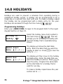
14.0 HOLIDAYS ...................................
14.1 Programming Holidays
2
78
................................................
Protege™ Integrated System User Manual
80
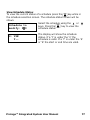
15.0 DAYLIGHT SAVINGS ......................
80
15.1 Daylight Savings Settings ............................................
82
16.0 SPECIAL FEATURES .......................
16.1
16.2
16.3
16.4
16.5
16.6
16.7
82
Offline Menu Access ....................................................
84
Offline Door Unlock .....................................................
85
Disable Audible Output ................................................
85
Messages ..................................................................
86
Panic Alarm ..............................................................
86
Fire Alarm ................................................................
87
Smoke Detector Reset ...............................................
17.1
17.2
17.3
17.4
17.5
17.6
17.7
17.8
88
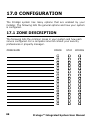
Zone Description .........................................................
89
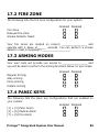
Fire Zone
..............................................................
89
Arming Modes
.......................................................
89
Panic Keys
..............................................................
82
Offline Menu Access
................................................
90
Offline Function Control
..........................................
90
Timers ....................................................................
91
Users
..............................................................
88
17.0 CONFIGURATION .........................
92
18.0 WARRANTY ..................................
92
18.1 Warranty Information ................................................
Protege™ Integrated System User Manual
3
1.0 INTRODUCTION
Thank you for choosing the Protégé Integrated Alarm and Access
Control System. The Protégé System will give you peace of mind by
providing reliable security protection, building automation and access
control for your premises.
The Protégé System is an advanced technology security system
specifically designed to enhance the functionality of security, building
automation and access control by providing a complete integrated
solution with local monitoring and offsite communication.
The elegant Protégé LCD Keypad allows complete control of your
security and access control system with a user friendly LCD display
and 24 key ergonomic keypad.
All the actions performed in your system will be executed and
displayed through the Protégé keypad. Therefore, before using your
Protégé Integrated Alarm and Access Control System, we highly
recommend you read this manual carefully and have your security
professional or property manager explain basic system operation to
you.
Please consult the configuration section on page 88 to find out how
your system is configured. Some features may not be available
depending on your system configuration.
Optional management software is available (Protégé System
Management Suite) and is recommended to enhance your
productivity when using the Protégé System. For more information
visit the Integrated Control Technology website or ask your System
Administrator.
4
Protege™ Integrated System User Manual
1.1 LEGEND
Indicates a warning or advisory message relating to the
section or location.
Indicates a hint or suggestion that relates to the section or
location.
[TEXT] Bold text enclosed in brackets is used to show key press
information or menu shortcut sequences.
Italics
Italic text shows a reference to a section or page.
1.2 TERMINOLOGY
To ensure that you manage your Protégé System effectively please
familiarise yourself with the following terms used throughout this
manual.
Areas / Partitions
An area or partition is used to divide large systems in to manageable
regions. For example a building may have a Warehouse Area,
Administration Area and Production Area. An area operates like an
individual alarm and is armed and disarmed independently.
Zone Inputs
Movement detectors, door contacts and other protection devices are
connected to the system on zone inputs. A zone belongs to an area to
protect the area and system from unauthorised entry. For example
the reception movement sensor zone would be assigned to the
Administration Area.
Trouble Zone Inputs
Trouble zones operate similar to zones however they are used to
monitor the status and condition of the system. For example if the
Protege™ Integrated System User Manual
5
enclosure door on the main control device is opened it will open the
Enclosure Tamper trouble zone.
PGM Programmable Outputs
PGM's or Programmable Outputs are used to control devices from the
Protégé System. A PGM can be used to activate lighting, activate a
siren, turn on an indicator or unlock a door.
Automation Outputs
Automation Outputs are used to control devices that are required to
be operated regularly by a user. For example Outdoor Lighting,
Irrigation or HVAC (Heating Ventilation and Air Conditioning) systems
can be connected to automation outputs.
Doors
When access control is enabled in a system, users are restricted
access by programming the doors in a door group. To gain entry or
exit from a door the user must present a Card, Key Tag or access the
door using an appropriate means (Keypad Control, Remote or System
Management Application).
LCD Keypads
LCD Keypads are used for all functions within the Protégé System and
are typically located near an entrance or door to allow areas within
the system to be armed and disarmed.
Card Readers
Card readers can be used to provide many functions within the
Protégé System. Primarily used to manage the access of users
through doors a card reader can also be used for time and
attendance, area arming and disarming, elevator access control and
car park management allowing the access control and alarm system
to be seamlessly integrated. Ask your installation company or
security professional for more information.
6
Protege™ Integrated System User Manual
Users
A user is a person or entity that uses the system to arm, disarm,
access a door or use a function within the system.
Access Level
An access level is assigned to a user and sets what functions the user
has access to on a keypad, what areas they can arm or disarm and
the doors and elevators they can access.
Menu Group
A menu group is assigned to an access level and is used to limit a
users ability to access certain functions on the LCD Keypad.
Area Group
Area groups are assigned to an access level and are used to control
the areas that a user can arm and disarm. An area group can be
assigned for arming and disarming. Areas assigned in the disarm area
group can also be armed by the user.
Door Group
Door groups are assigned to an access level and are used to control
access through the doors within the door group.
Floor Group
Floor groups are assigned to an access level and are used to control
access to floors in an elevator. You must also be assigned an elevator
group.
Elevator Group
Elevator groups are assigned to an access level and are used to
control access to a group of elevators. You must also be assigned a
floor group to define the floors you are allowed to access.
Protege™ Integrated System User Manual
7
2.0 OPERATION
The following section provides you with information on how to use the
Protégé LCD Keypad.
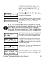
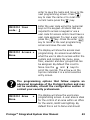
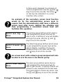
When the text [USER CODE] is shown this indicates
that you are required to logon with your user code.
The default Master Code to gain access to your
system is
followed by the ENTER
key.
This code MUST be changed, see section 5.0 on page
41 on how to add and modify user codes.
Many of the features and options MUST be enabled by
the installation company or security professional.
Refer to the system configuration tables in section
17.0 on page 88 to view the configuration of your
system.
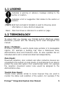
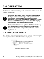
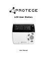
2.1 INDICATOR LIGHTS
The Protégé LCD keypad features three status indicator lights
showing the condition of the Protégé Security System.
Power / Trouble Indicator
Disarmed Indicator
Armed / Alarm Indicator
Figure 1 - Indicator Lights
8
Protege™ Integrated System User Manual
Power / Trouble Indicator
When FLASHING, indicates that there is a trouble condition present.
When ON, the system is powered and operating normally. If there is
a complete power failure this indicator will be OFF.
Disarmed Indicator
Indicates when the system is disarmed. When ON, the system is
disarmed, enter your user code to arm.
Armed / Alarm Indicator
When FLASHING the system is in alarm and you need to enter your
user code to silence the alarm. When ON, the system is armed, enter
your user code to disarm.
Indication of the system status and the operation of
the indicators are programmable and may not
function as above. Verify the operation with your
installation company or security professional.
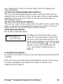
2.2 VISUAL DISPLAY
The Protégé LCD keypad features a rich 32 Character LCD (Liquid
Crystal Display) showing customised messages. All messages are
shown on the LCD display screen.
2.3 AUDIBLE TONE
When you press a key on the Protégé LCD keypad a short audible
tone is generated. Other tones are generated when certain functions
are used, you should be familiar with the following audible tone
outputs.
Protege™ Integrated System User Manual
9
Confirmation Tone
When an operation is successfully completed on the keypad the
keypad generates a series of four audible tones. The display will also
show the success or failure of the operation.
Rejection Tone
When the system times out or when an operation is incorrectly
entered on the keypad, it will generate a continuous audible tone for
three seconds.
If required the audible key press tone can be silenced
by pressing and holding the
key for 3 seconds.
This option must be enabled by your security
professional or system administrator.
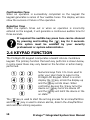
2.4 KEYPAD FUNCTION
The Protégé LCD keypad incorporates a backlit silicone membrane
keypad. The primary function that each key performs is shown below,
in some cases these may vary based on the function or action being
performed.
Numerical keys from 0 to 9 are used to
enter your User Code to logon to the
Protégé LCD Keypad. When in a scroll
display the
key scrolls the display up
and the
key scrolls down. When
controlling devices the
key turns the
device on,
key turns the device off
and the
key will latch the device in the
on state.
The
key is used to start the arming process for an Area/Partition
and the
key is used to silence alarms, disarm the Area/Partition
and cancel an arming sequence.
10
Protege™ Integrated System User Manual
The stay arming
key is used to start the stay arming process
for an Area/Partition, refer to the Stay Arming Section 3.4 on Page
32.
The force arming
key is used to force arm an Area/Partition,
refer to Force Arming Section 3.5 on Page 34.
The memory
key provides a shortcut to the memory view menu
from the area control screen, to perform a text search action or a
jump function from a programming list selection entry.
The menu
key is used to access the menu and can be followed
by menu shortcut selection key(s), the numerical key representing
the menu item.
The enter
key is used to confirm an action on the keypad,
acknowledge memory and alarm information and move to the next
programming screen.
The clear
key will log off the user currently logged on the
keypad. When pressed while not logged in the display will be
refreshed.
Arrow keys are located on the navigation
pad and are used to scroll the menu,
move the focus of a program window to
the next screen and move the cursor
when programming or editing values.
The function
key can be programmed to unlock a door. Refer to
the Configuration Section on Page 88 for more information.
The bypass
key can be pressed when a zone is breached during
an arming process to bypass the displayed zone. Refer to the
Configuration Section on Page 88 for more information.
Protege™ Integrated System User Manual
11
2.5 TEXT ENTRY
The Protégé LCD keypad can be used to program text names for
objects in the system (Users, Zones, Areas and Doors). To program
the text value the numerical keys operate similar to the text entry on
a telephone.
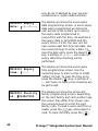
Entering text data is done by pressing
keys multiple times to show the
character required. The display will
change as the key is pressed. Using the
character key map shown, to enter the
name John, the
key is pressed once
move the cursor one location to the right
with the
key. Press the
key seven
times and repeat the procedure for the
other characters in the text entry.
For more productive management of a Protégé
System ask your security professional about the
Protégé System Management Suite.
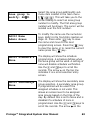
2.6 OPTION ENTRY
The Protégé LCD keypad uses option programming entry when
configuring a yes or no option setting. Option screens are shown with
eight characters enclosed in '[' brackets.
Numerical Option Key Entry
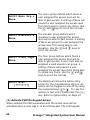
If an option is enabled the corresponding number will be shown or
when disabled a '*' will be shown in place of the option.
UN00010 Misc
[*****6*8]
12
In the example shown option 6 and 8 are
enabled. The example shows the
Protege™ Integrated System User Manual
miscellaneous options group when
programming a user.
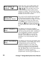
Detailed Text - Option Key Entry
In many cases options are not known by the numerical number
alone. In this case the Protégé System provides a text based entry
system for options allowing the complete system to be programmed
without the need for a reference manual.
UN00010 Misc
[*****6*8]
1. Show greeting
at user logon: N
In any option entry screen press the
key. The display will change and now
show you the text description of the first
option in the option entry location that
you are programming.
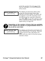
In any option entry screen press the
key. The display will change and now
show you the text description of the first
option in the option entry location. Press
the
key to toggle the option state ('Y'
or 'N'). Use the
and
key to scroll
the options within the option entry.
When the required options have been set
press the
key and you will be
returned to the option entry screen
where the changes you have made will
be applied. Press
to save your
changes and proceed to the next
programming screen.
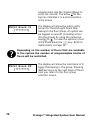
2.7 TEXT SEARCH
The Protégé LCD User Station features a powerful text search
function that allows you to find items that have been given text
names.
Protege™ Integrated System User Manual
13
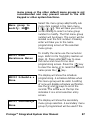
In the following example the name for a user is searched for from the
user selection screen when programming the user. If the text
searching option is available for a record, pressing the memory
button will open the search entry.
Select user to
modify: UN00001
Search details
_
[ENTER] to find
J
[Ð] Find next
JAMES COOK
From the user selection screen press the
key to open the search screen. The
display will then show the text search
entry.
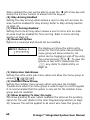
Use the keypad to enter the text data
that you want to search for in the search
details screen. In our example we want
to find the user James Cook. To cancel
the search press
to return to the
screen were you selected the search.
When you press the
key to get the 'J'
in James, the display will change with the
prompt telling you to press
to find
the text shown. Complete the entry to
get the first three characters. You can
enter up to the full 16 characters.
When you press the
key the system
will begin the search. If a record is found
matching the text you have entered the
record will shown. The top line will
prompt you to find the next record by
pressing the
key.
Press
or
14
to return to the search screen
right arrow to delete the entry.
Protege™ Integrated System User Manual
Jumping To Search Results
To use the information that is found by the search press the
to jump to the record.
key
2.8 MENU OPERATION
The Protégé LCD keypad uses a well defined menu structure.
Shortcuts are provided to these menus without the need to scroll
using the up and down arrow keys. Throughout this manual a keypad
menu shortcut will be shown as [
,
, ]. To execute the
shortcut press the
key and then the numerical keys
that
follow.
The Protégé LCD Keypad Menu is structured as detailed in the
following sections. The installer menu [
,
] is omitted from this
manual and should only be accessed by a professionally certified
security installer.
Main Menu
The main menu contains all of the menus in the system. A user can
only view menus that are assigned to the menu group in the
programmed access level.
1.
2.
3.
4.
5.
6.
7.
8.
Area Control
User
Event Review
Installer
View
Time
Bypass
System
(Arming and Disarming Areas)
(Programming Users)
(Reviewing Event Log Information)
(Installer Only Access)
(System View and Control)
(Set Time and Schedules)
(Bypass/Isolate Zone)
(System Functions)
Protege™ Integrated System User Manual
15
Area Control
To access the area control menu (by default you will be taken to the
area control menu automatically when you logon to the LCD Keypad)
press [
,
].
User (Sub Menu)
To access the user programming menu press [
following user sub menus are available.
1.
2.
3.
4.
5.
6.
Add/Modify
Menu Groups
Door Groups
Area Groups
Access Level
View Status
Review
Hex Review
Stats
Alarm Memory
Trouble View
Bypass List
Time (Sub Menu)
To access the time menu press [
menus are available.
16
,
]. The following
(Review System Events)
(Installer Only Access)
(Installer Only Access)
View (Sub Menu)
To access the view menu press [
menus are available.
1.
2.
3.
]. The
(Add/Modify Users)
(Menu Group Programming)
(Door Group Programming)
(Area Group Programming)
(Access Level Programming)
(View Users Current Location)
Event Review (Sub Menu)
To access the event log review menu press [
event sub menus are available.
1.
2.
3.
,
,
]. The following view sub
(View Alarm Memory)
(View System Troubles)
(Display All Bypassed Zones)
,
]. The following time sub
Protege™ Integrated System User Manual
1.
2.
3.
4.
Change Time
Schedules
Holidays
Daylight
(Set/Adjust Real Time Clock)
(Add/Modify Schedules)
(Add/Modify Holidays)
(Set Up Daylight Savings)
Bypass (Sub Menu)
To access the bypass menu press [
sub menus are available.
1.
2.
Zone
Trouble Zone
Answer Call
Call Remote
Test Report
]. The following bypass
(Bypass Zone Inputs)
(Installer Only Access)
System (Sub Menu)
To access the system menu press [
sub menus are available.
1.
2.
3.
,
,
]. The following system
(Answer Incoming Remote Call)
(Call Remote Upload Computer)
(Send Monitoring Test Report)
2.9 OFFLINE MENU OPERATION
The Protégé LCD User Station also provides an offline menu that
allows quick access to certain menu functions while you are logged
out. To view the Offline Menu press the
key.
Offline Menu
The offline menu contains four menus that are provided without the
need to log in to the system.
1.
2.
3.
4.
Automation
Trouble View
Events
System Info
(Control Automation Points)
(View Trouble Conditions)
(Review System Events)
(View System Information)
Protege™ Integrated System User Manual
17
2.10 LOGON TO LCD KEYPAD
Before most operations a user MUST logon to the Protégé System
LCD Keypad.
Logon Procedure
To logon to the Protégé LCD Keypad follow the procedures below.
Enter user
code: ******
Good Evening
J Smith
Warehouse
is DISARMED
Enter your [USER CODE] +
to
logon to the Protégé System LCD
Keypad. Each key press will display a '*'.
To restart the entry process press the
clear
key.
If the correct code is entered you will be
presented with a welcome screen
greeting you with the time of day.
If the user is programmed to view alarm
memory the alarm memory message will
be shown to the user before they are
automatically taken to the area control
menu.
If enabled the display will then proceed
to the area control menu [
, ] or to
the main menu depending on the user
configuration.
Log Off Procedure
The keypad will automatically log the user off after no key press for
the programmed time or if the clear
key is pressed at any time
while the user is logged on.
The welcome screen display, alarm memory display
and other display options can be configured per user
18
Protege™ Integrated System User Manual
or per access level. Refer to the User Programming
Section on Page 41.
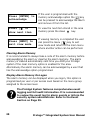
2.11 ALARM MEMORY
All zones that generate an alarm can optionally be stored in the event
log and/or the alarm memory for the area that the alarm was
activated.
Alarms in memory
logon to view.
If an alarm has occurred on your system
and the alarm memory display option is
enabled the display will show the alarm
memory screen.
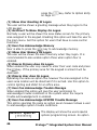
Viewing Alarm Memory
Enter your [USER CODE] to logon to the keypad. Refer to the Logon
Keypad Section on Page 18.
Select the memory view menu item
Warehouse
located in the view main menu [
, ,
*Alarms In Mem*
]. Use the up
and down
keys
to scroll the areas that can be viewed. If
an area has alarms in memory the
keypad will generate a rejection tone
beep and the display will show the
memory message.
Had alarm on
Roller Door
To view the first item stored in the area
memory press the enter
key. The
first alarm stored will be displayed and
the screen will scroll the information.
in AREA
Warehouse
The display will then show the area that
the alarm occurred. If a tamper alarm
occurs the first line will state that it was
a 24HR alarm.
Protege™ Integrated System User Manual
19
Press [ENTER] to
acknowledge
If the user is programmed with the
memory acknowledge option the
key
can be pressed to acknowledge the alarm
and remove it from the list.
Press [Ð] to
show next item
To view the next item stored in the area
memory press the down
key.
Press [MENU] to
exit view mode
If viewing memory is completed the user
can press the menu
key to exit
view mode and return to the main menu
where another action can be performed.
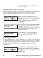
Clearing Alarm Memory
It is recommended to always take a note of the alarm memory before
acknowledging the alarm or clearing the alarm memory. The alarm
memory is cleared automatically next time you ARM your Protégé
system if the clear memory option is enabled for the area.
Alternatively the alarm memory can be acknowledged by a user that
has the acknowledge option programmed.
Display Alarm Memory On Logon
The alarm memory can be displayed when you logon, this option is
programmed per user or per access level based on the menu group
assigned to the access level.
The Protégé System features comprehensive event
logging and full audit information. It is recommended
to review the event log for alarm events or inform the
security system administrator. Refer to the Event
Section on Page 39.
20
Protege™ Integrated System User Manual
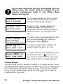
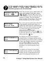
2.12 TROUBLE DISPLAY
The Protégé Security System continually performs self diagnostics of
system devices and monitors trouble conditions that can occur on
your system.
System Trouble
logon to view.
If a trouble condition is present in the
system and trouble display option is
enabled for the LCD Keypad the display
will show the system trouble screen.
Trouble conditions are cleared automatically by the
system. If required these can be programmed to
require acknowledgement. It is recommended that
you inform your property manager or security
company immediately if a trouble condition occurs.
When a trouble condition occurs the Protégé keypad
can be programmed to generate an audible tone
every 120 seconds. The trouble tone is cancelled
when the trouble condition is viewed or the condition
is returned to normal. Refer to the Disable Audible
Output section on Page 85 to disable the keypad beep
tone.
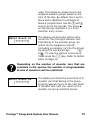
Viewing System Troubles
Enter your [USER CODE] to logon to the keypad. Refer to the Logon
Keypad Section on Page 18.
Select the trouble view menu item
*Battery*
located in the view menu [
, , ].
The system or a
This will take you to the trouble view
menu. If a trouble condition exists the
first trouble will be shown.
Protege™ Integrated System User Manual
21
The trouble view menu can also be accessed from the
offline menu, this option must be enabled by your
security professional. Refer to the Offline Menu
section on Page 82.
The trouble message will scroll to show
the full details of the trouble condition
and action that should be taken.
component of it
has a battery
As shown in the example display the
trouble message "The system or a
component of it has a battery problem.
Call service tech." is presented to the
user.
problem. Call
service tech.
Press [ENTER] to
acknowledge
Press [Ð] to
show next item
Press [MENU] to
exit view mode
If troubles require acknowledgement the
user can acknowledge the trouble by
pressing the enter
key.
To view the next trouble condition (if
present) press the down
key.
If viewing memory is completed the user
can press the menu
key to exit
view mode and return to the main menu
were another action can be performed.
Trouble Groups
Trouble groups split the available troubles in to categories that can be
viewed separately. When a trouble condition occurs in a trouble group
the trouble group title will be shown in place of the trouble condition
in the normal trouble display. Press the enter
key to view the
troubles within the group.
22
Protege™ Integrated System User Manual
2.13 GENERAL TROUBLE LIST
General trouble conditions monitor the system devices and functions
for trouble conditions that affect all aspects of the system.
AC Mains Failure
AC or Mains power that is supplying one of the devices in the system
has been lost and that device is operating on standby battery power.
Low/Missing Battery
A battery is either low or damaged and is not able to provide
adequate backup power to a device in the system.
Clock Inaccurate
The real time clock used to log event data is inaccurate. Set the time
using the time menu.
Reporting
The system has failed to send a reportable message to the security
monitoring company. Inform the security monitoring company of the
trouble condition.
Telephone Line
The telephone line that is connected to the main system controller
has been damaged.
Zone Fault
A zone that has been programmed with fault monitoring is in a
compromised condition and needs to be serviced.
Fire Loop
The fire detection wiring or a fire detector has become faulty.
Fire Zones and Fire Loop trouble detection MUST be
enabled by your security professional or installation
Protege™ Integrated System User Manual
23
company. Refer to the Configuration Section on Page
88.
System Power
An electronic protection device used to limit current to external
devices has tripped due to excessive loading on the circuit.
Siren/Bell Output
A siren or bell warning output is disconnected or excessive loading
has caused the output to shutdown.
2.14 SYSTEM TROUBLE LIST
System trouble conditions monitor the system devices that are used
to connect the system to zones, readers and other ancillary
equipment.
Module Tamper
A module enclosure has been opened and security is potentially
compromised.
Module Communication
Communication with a module or device is momentarily interrupted
or the device has been removed from the system.
Module Security
A module or device has attempted to register with the system when
the system has the network security option enabled.
System Hardware
A hardware component has failed and needs to be serviced.
24
Protege™ Integrated System User Manual
2.15 ACCESS TROUBLE LIST
Access control trouble conditions monitor user operation and access
control devices within the system alerting the system manager when
a user is attempting to compromise the system or a device is in an
unauthorised state.
Forced Door
A door in the system has been forced open. A forced door occurs if
entry or exit from the door results in the door being forced open. A
forced door trouble condition may also occur when a door unlock
emergency break glass has been activated.
Door Left Open
A door in the system has been left in the open state or has been held
open beyond the programmed door open time.
Number Of Access Attempts
An unauthorised user has exceeded the number of times they can
attempt to gain entry in to a door or the user has entered an
excessive number of incorrect PIN numbers on a LCD Keypad.
User Denied Entry
An unauthorised user has attempted to gain entry through a door.
Unknown Card
A card that is not programmed in to the system has been presented
to a card reader.
Card Reader Tamper
A card reader has been removed or damaged and has failed to report
to the system.
Protege™ Integrated System User Manual
25
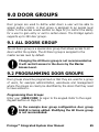
2.16 BYPASSED ZONE LIST
The bypass list is accessed from the view sub menu [
, , ]
and will list all bypassed zones in the system. To bypass zones in the
system refer to the section Bypassing Zones on Page 36.
Zone(s) bypassed
logon to view.
The display will be shown when zones
are bypassed in the system and the LCD
Keypad is configured to display bypass
messages.
Viewing Bypassed Zones
Enter your [USER CODE] to logon to the keypad. Refer to the Logon
Keypad Section on Page 18.
Checking zone(s)
for bypass...
When the bypass list has been completed
the display will show the completed
message.
Bypass list
completed.
Roller Door
Find next zone ?
26
Select the bypass view sub menu item
located in the view menu [
,
, ].
This will take you to the bypass view
menu. Bypassed zones will be scanned
and reported to the display.
If a zone is found in the system that is
bypassed the display will show the zone
name and prompt you to find the next
zone. Press the down
key to
continue searching for bypassed zones or
press the menu
key at any time to
perform another action.
Protege™ Integrated System User Manual
3.0 ARMING/DISARMING
To take full advantage of your Protégé System, you should familiarize
yourself with the different arming methods.
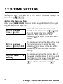
3.1 EXIT DELAY
After entering a valid arming sequence the exit delay time will
provide you with enough time to exit the protected area before the
area arms. The keypad will generate a beep-beep tone repeatedly
during the exit delay period.
The configuration of the exit delay beeper is
dependent on the installation. Please verify the
operation with your security professional or property
manager.
3.2 DISARMING AREAS
An entry point, like a front door, will be programmed with an entry
delay time for an area. When an entry point is opened, the keypad
will emit a continuous audible tone until you disarm the area. Your
Protégé System will not generate an alarm until this timer elapses
allowing you time to disarm the area. Any zone activation on a zone
that is not designated as an entry zone will result in the alarm
activating.
Disarming Your Area
Logon to the LCD Keypad by entering your [USER CODE] followed by
the enter key. Refer to the Logon Keypad Section on Page 18.
Warehouse
is ARMED
The display will show the area associated
with the LCD Keypad you have logged on
Protege™ Integrated System User Manual
27
to and the current status. If you have
access to more than one area you are
able to scroll the areas using the
and
keys.
To search for an area by name press the
key to open the search screen.
Refer to Text Searching on page 13.
Warehouse
in ENTRY delay
If you have triggered an entry zone the
display will show the 'in ENTRY delay'
message for the area you have selected.
Warehouse
is DISARMING
Press the
disarm key to start the
disarming process. The display will show
the progress.
Warehouse
is DISARMED
Once the disarming process has
completed the display will show the area
as being disarmed. You may now
proceed to enter the area and alarms will
not be activated.
Silencing and Cancelling Alarms
Logon to the LCD Keypad by entering your user code followed by the
enter key. Refer to the Logon Keypad Section on Page 18.
Warehouse
in ALARM
The display will show the area associated
with the LCD Keypad you have logged on
to with the alarm status. If you have
access to more than one area you are
able to scroll the areas using the
and
keys.
To search for an area by name press the
28
Protege™ Integrated System User Manual
key to open the search screen.
Refer to Text Searching on page 13.
Warehouse
is DISARMING
Press the
disarm key to silence the
alarm and start the disarming process.
The display will show the disarming
progress.
Warehouse
is DISARMED
Once the disarming process has
completed the display will show the area
as being disarmed and the alarms will be
silenced.
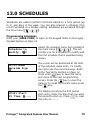
3.3 REGULAR ARMING AREAS
Regular arming of an area will enable all of the zones in the area and
start an exit delay timer allowing you to exit the area.
Regular Arming Areas
Logon to the LCD Keypad by entering your [USER CODE] followed by
the enter key. Refer to the Logon Keypad Section on Page 18.
Warehouse
is DISARMED
The display will show the area associated
with the LCD Keypad you have logged on
to and the current status. If you have
access to more than one area you are
able to scroll the areas using the
and
keys.
To search for an area by name press the
key to open the search screen.
Refer to Text Searching on page 13.
Protege™ Integrated System User Manual
29
Warehouse
Enabling zone(s)
Press the
arm key. The area will
enable the zones in the area. The display
will show the progress.
Warehouse
Checking zone(s)
Once the enabling of the zones has been
completed the area will now ensure that
the zones in the area are ready to be
armed.
If an area has zones that are not ready to be armed
and are not secured the display will show you the first
zone that is open in the area, refer to the following
section explaining how to arm an area with open
zones.
Warehouse
Arm complete
Warehouse
in EXIT delay
If all the zones are ready the area will
complete the arming process and briefly
display the message "Arm Complete" to
you.
After the display period for the arm
complete message the display will return
to the area status display and show the
exit delay. You should now leave the
area.
Regular Arming An Area With Open Zones
When an area has open zones an action needs to be taken by the
user to complete the arming process.
Logon to the LCD Keypad by entering your [USER CODE] followed by
the enter key. Refer to the Logon Keypad Section on Page 18.
Warehouse
is DISARMED
30
The display will show the area associated
with the LCD Keypad you have logged on
Protege™ Integrated System User Manual
to and the current status. If you have
access to more than one area you are
able to scroll the areas using the
and
keys.
Warehouse
Enabling zone(s)
Press the
arm key. The area will
enable the zones in the area. The display
will show the progress.
Warehouse
Checking zone(s)
Once the enabling of the zones has been
completed the area will now ensure that
the zones in the area are ready to be
armed.
If an area has zones that are not ready to be armed
and are not secured the display will show you the first
zone that is open in the area. See force arming to
force arm the zone or press the
key to bypass the
displayed zone and continue with the arming process.
Roller Door
is OPEN
When the zone is not ready to be armed
the display will show the zone name on
the first line and the zone status below.
Press [ARM] to
re-test zone(s)
The display will then scroll showing the
available options for the zone. Pressing
the
arm key will start the zone test
from the beginning.
Press [Ð] to
view next zone
Press [FORCE] to
force arm area.
Pressing the
key will show the next
open zone in the system.
If the area that has been selected can be
force armed the option to force arm the
Protege™ Integrated System User Manual
31
area will be shown. Pressing the
key
will start the force arming. A zone must
be able to be force armed to allow this
option to operate correctly.
Press [BYPASS]
to bypass zone.
If the zone that is shown is able to be
bypassed and the user is allowed to
bypass zones (they must have the menu
option enabled). Pressing the
key
will bypass the zone and proceed with
the arming operation. The bypass menu
can also be accessed directly by the
menu shortcut [
, , ].
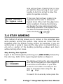
3.4 STAY ARMING
This method of arming allows you to remain in the protected area
while partially arming the system. Stay zones are zones that are
bypassed when the system is stay armed. For example, if you are
working late or going to sleep and the stay option is programmed you
can arm a portion of the building protecting windows and doors
without arming other zones.
Stay Arming Your System
Logon to the LCD Keypad by entering your [USER CODE] followed by
the enter key. Refer to the Logon Keypad Section on Page 18.
Office
is DISARMED
The display will show the area associated
with the LCD Keypad you have logged on
to and the current status. If you have
access to more than one area you are
able to scroll the areas using the
and
keys.
To search for an area by name press the
32
Protege™ Integrated System User Manual
key to open the search screen.
Refer to Text Searching on page 13.
Office
Enabling zone(s)
Press the
stay key. The area will
enable the normal zones in the area and
bypass the stay zones. The display will
show the progress.
Office
Checking zone(s)
Once the enabling of the zones has been
completed the area will now ensure that
the zones in the area are ready to be
stay armed.
Office
Arm complete
If all the zones are ready the area will
complete the arming process and briefly
display the message arm complete to
you.
Office
in EXIT delay
Office
is STAY ARMED
After the display period for the arm
complete message the display will return
to the area status display and show the
exit delay. You should now leave the
area.
On completion of the exit delay the
display will return to the area status
display and show the area status as
being stay armed.
Switching From Stay To Regular/Force Armed
To change an area from stay armed to a regular or force armed mode
follow the procedures for disarming an area and then arm the area
using the method required.
Protege™ Integrated System User Manual
33
3.5 FORCE ARMING
Force Arming allows you to rapidly arm the system without waiting
for all zones in the system to close. During force arming, a forced
zone is considered deactivated until it closes, then the system will
arm that zone. Force arming is commonly used when a motion
detector is protecting the area occupied by a keypad. For example,
when arming and the motion detector is programmed as a force
zone, the system will allow you to arm even if the zone is open.
Force Arming Your System
Logon to the LCD Keypad by entering your [USER CODE] followed by
the enter key. Refer to the Logon Keypad Section on Page 18.
The display will show the area associated
with the LCD Keypad you have logged on
to and the current status. If you have
access to more than one area you are
able to scroll the areas using the
and
keys.
Office
is DISARMED
To search for an area by name press the
key to open the search screen.
Refer to Text Searching on page 13.
Office
Enabling zone(s)
Office
Checking zone(s)
34
Press the
force key. The area will
enable the zones in the area. The display
will show the progress.
Once the enabling of the zones has been
completed the area will now ensure that
the zones in the area are ready and
automatically skip any open zones that
can be force armed.
Protege™ Integrated System User Manual
Office
Arm complete
Office
in EXIT delay
Office
is FORCE ARMED
If all the zones are ready the area will
complete the arming process and briefly
display the message arm complete to
you.
After the display period for the arm
complete message the display will return
to the area status display and show the
exit delay message. You should now
leave the area.
On completion of the exit delay the
display will return to the area status
display and show the area status as
being force armed.
3.6 AREA 24HR STATUS
All available areas also contain an individual 24HR tamper section
that continuously monitors the status of connected devices in the
area. When maintenance is being performed on an area the installer
can disable the 24HR monitoring of an area without disrupting other
areas.
The 24HR section of an area can only be managed by the installer or
a user programmed with the appropriate option. By default users are
not provided access to the 24HR area.
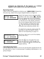
Controlling The 24HR Area Section
Logon to the LCD Keypad by entering your [USER CODE] followed by
the enter key. Refer to the Logon Keypad Section on Page 18.
Office
is DISARMED
The display will show the area associated
with the LCD Keypad you have logged on
to and the current status. If you have
Protege™ Integrated System User Manual
35
access to more than one area you are
able to scroll the areas using the
and
keys.
To search for an area by name press the
key to open the search screen.
Refer to Text Searching on page 13.
Office
24HR Enabled
Once the area is shown, Press the
key. The display will now show the status
of the 24HR section of the area.
Office
24HR Disabled
Press the
disarm key to disable the
24HR section or the
arm key to
enable the 24HR section.
Office
24HR Busy
While
completing
the
requested
operation on the 24HR area the display
will briefly show the busy message to
indicate that it is completing the required
action.
The 24HR section of an area is enabled automatically
when the area is armed.
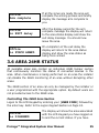
3.7 BYPASSING ZONES
Bypassing zones allows you to program the alarm system to ignore
(Bypass/Deactivate) specified zones the next time the system is
armed or until the bypass is removed (Bypass/Deactivate Latched).
For example, you may wish to bypass certain zones when workers
are renovating part of your establishment.
A zone will automatically have the bypass settings
removed when all areas to which the zone has been
36
Protege™ Integrated System User Manual
assigned are disarmed. If the bypass is a latched
bypass it will remain until removed manually.
Bypassing Zones
Logon to the LCD Keypad by entering your [USER CODE] followed by
the enter key. Refer to the Logon Keypad Section on Page 18.
Roller Door
is not BYPASSED
Select the bypass zones sub menu item
located in the main menu [
,
, ].
This will display the first zone available
to be bypassed. The name will be shown
on the first line of the display and then
the current bypass status will be shown
on the second line. Pressing the right
key will prompt you for the zone
using the zone reference (CP001:01).
To search for a zone by name press the
key to open the search screen.
Refer to Text Searching on page 13.
Warehouse PIR
is not BYPASSED
Warehouse PIR
is BYPASSED
Use the up
key to scroll the display
to the next zone.
Press the
key to bypass the zone.
Press the
key to latch bypass the
zone or press the
key to remove the
bypass setting.
Latch Bypassing Zones
Latched bypassing allows a zone to be permanently bypassed and can
be used when a zone is removed due to building maintenance or on
going changes.
Protege™ Integrated System User Manual
37
The list of zones that are available to be bypassed are
dependent on the configuration settings of a keypad
and the area being controlled. In some cases zones
may not be available to be bypassed, in such a case a
message will be shown to you.
38
Protege™ Integrated System User Manual
4.0 EVENTS
Events are logged for all actions that are performed on the Protégé
System and can be viewed from the LCD Keypad. Events are
presented in plain text on the keypad.
To manage your system effectively and get detailed,
exception and custom reports direct to your desktop
ask your security professional about the Protégé
System Management Suite.
4.1 VIEWING EVENTS
Viewing events can be accessed from the event review menu or from
the offline menu. For information on offline menu functions refer to
the Offline Menu Operation section on Page 82.
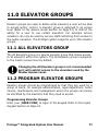
Viewing Events
Enter your [USER CODE] to logon to the keypad. Refer to the Logon
Keypad Section on Page 18.
Wed 13:27:41 Use
r OFFLINE USER L
r OFFLINE USER L
ogged in at KP00
Select the event review sub menu item
located in the main menu [
, , ].
This will take you to the screen
displaying the most recent event that
has occurred in the system. To move to
the previous event press the
key or
to move to the next event press the
key.
The first 32 characters of the event will
be shown. Pressing the
key will
Protege™ Integrated System User Manual
39
scroll the display up one line to show the
next line for the event.
ogged in at KP03
9
Pressing the
key again will scroll the
display up one more line to show the
remainder of the event.
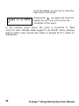
In the example shown above the event is converted to "Wed
13:27:41 User OFFLINE USER Logged In At KP039" clearly showing
that an offline menu access was made on Keypad 39 at 1:30pm on
Wednesday.
40
Protege™ Integrated System User Manual
5.0 USER CODES
User Codes are personal identification numbers that allow you to
enter certain programming modes, arm or disarm your Protégé
system as well as activate or deactivate automation functions. The
Protégé system supports multiple master codes and over two
thousand user codes.
5.1 MASTER CODE
The master code can perform all functions within the protégé system
and is used to program and configure all user functions. The default
master is
followed by the enter
key.
5.2 DURESS CODE
If you are forced to arm or disarm your system, entering the user
code assigned with the duress code option will arm or disarm the
system and immediately transmit a silent message (Duress Code) to
the security monitoring station.
Duress Codes MUST be programmed by your security
professional or installation company who will provide
you with the operating instructions. Please refer to
the System Configuration Section on Page 88.
5.3 PROGRAMMING USER CODES
Your Protégé system uses one to eight digit user codes, where each
digit can be any value from 0 to 9. Avoid programming simple or
obvious user codes, such as part of your telephone number or
address and codes such as 1234, 1111 or 1212.
Protege™ Integrated System User Manual
41
Programming User Codes
Enter your [USER CODE] to logon to the keypad. Refer to the Logon
Keypad Section on Page 18.
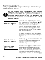
In the example user configuration user number
UN00010 is being edited. Modifying the master code
or other codes within the system is not advised as
this may prevent access to the LCD Keypad if the
master code is deleted or modified from the default
settings in error.
Select user to
modify: UN00001
Select the user add/modify sub menu
item located in the main menu [
,
, ]. This will take you to the screen
asking to select a user number to
modify. The initial user number will be
the user number who logged in to the
LCD Keypad. The cursor will be located
over the first number.
To search for users by their name press
the
key. Refer to Text Searching on
Page 13.
Select user to
modify: UN00010
UN00010 Name
*User 00010
42
Use the up
key to increment the user
number until UN00010 is displayed or
enter the user number using the
numerical keys.
Press the enter
key and the display
will show the user display name. The
cursor will be positioned at the start of
the text entry. To modify the name use
the numerical keys. Refer to the Text
Entry Section on Page 12. Press the
Protege™ Integrated System User Manual
enter to save the name and move to the
next programming screen. Press the
key to clear the name or to recall the
current name press the
key.
Enter the user code using the numerical
keys on the keypad. All users that are
required to access a keypad or use a
user code for access control must have a
user code assigned. To clear a user code
press the
key. Press the enter
key to move to the next programming
screen and save the user code.
UN00010 User
code: _
UN00010 Access
None
Î
The display will show the access level
programming. An access level defines
what the user is able to access within the
system and contains the menu, area,
floor, elevator and door groups that can
be assigned. By default this is set to
None. Use the
and
keys to
scroll the records. The arrow Î on the
top line indicates it is a scroll selection
entry screen.
The programming options that follow require an
advanced knowledge of the Protégé System and may
not be available, consult the configuration section or
contact your security professional.
UN00010 Area
None
Î
The display will show the users area
programming screen. A user area is ideal
for the control of an area within an office
for the alarm, HVAC and lighting. By
default this is set to None and should
Protege™ Integrated System User Manual
43
only be set if advised by your security
professional or system administrator.
UN00010 Expiry
date: --/--/----
The display will show the users expiry
time programming screen. Use the
numerical keys to enter a time in 24HR
military format. To clear the time entry
press the disarm
key. A setting of -:-- will mean no expiry time checking will
be performed.
UN00010 Expiry
time: --:--
UN00010 Facility
id: 4294967295
44
The display will show the users expiry
date programming screen. A users expiry
date when programmed will allow the
user access to the system up to and on
the expiry date programmed in
conjunction with the time. An example if
the expiry date is 14/5/2004 and the
expiry time is 13:45, the user will not
have access past this time and date. Use
the numerical keys to enter a date. To
clear the date entry press the disarm
key. A setting of --/--/---- will mean no
expiry date/time checking will be
performed.
The display will show the users card
facility programming screen. Depending
on the card facility and card number type
the screen may differ from shown. Use
the numerical keys to enter the card
facility code. To load a users card from a
reader press the
key and present a
card. To clear the entry press the
Protege™ Integrated System User Manual
key. A setting of 4294967295 will mean
no facility id is programmed.
The facility code of a users card is NOT normally
printed on the card. The facility code is also referred
to as the family number, site code or issue id. Verify
with your security professional if you are not sure of
the facility code for cards.
UN00010 Card
no: 4294967295
The display will show the users card
number programming screen. Depending
on the card facility and card number type
the screen may differ from shown. Use
the numerical keys to enter the card
number code. A card number is typically
printed on the card device. To clear the
card number press the disarm
key.
A setting of 4294967295 will mean no
card number is programmed. The card
number and facility code MUST be
prefixed with leading zeros if less than
the digits displayed.
To automatically load a large number of users cards
enter 'autoload' card entry mode. Refer to the section
following. To program large numbers of users or
import an existing user table from an excel or CSV file
ask your security professional about the Protégé
System Management Suite.
UN00010 Misc
[********]
The display will show the users
miscellaneous options programming
screen. An option can be toggled on and
off by using the numerical keys
to
.
To view the options in text entry mode
Protege™ Integrated System User Manual
45
press the
on Page 12.
key. Refer to Option Entry
(1) Show User Greeting At Logon
The user will be shown a greeting message when they logon to the
LCD keypad.
(2) Go Direct To Menu Display On Logon
Normally a user will be shown the area status screen for the primary
area assigned to the keypad. Enabling this option will take the user to
the main menu. Set this option for users that have no area control
functions.
(3) User Can Acknowledge Memory
User is able to press the
key to acknowledge memory.
(4) Show User Memory On Logon
The user will be shown the alarm memory when they logon. It is
recommended to also enable option three when option four is
enabled.
(5) Disarm Primary Area On Logon
When enabled the user only needs to enter their user code and press
the
key. If the primary area for the keypad is armed it will be
disarmed.
(6) Disarm User Area On Logon
Operating the same as option five however the area assigned in the
users area location will be disarmed if it is armed. Use this option to
control lighting and HVAC for an office area.
(7) User Can Acknowledge Trouble Message
When enabled this option will give the user permission to
acknowledge trouble conditions in the system when the require
trouble acknowledgement is enabled.
(8) User Can Acknowledge SYSTEM Trouble Message
This option operates the same as option seven however allows a user
to acknowledge system trouble conditions.
UN00010 Special
[********]
46
The display will show the users special
options programming screen. An option
Protege™ Integrated System User Manual
can be toggled on and off by using the
numerical keys
to
. To view the
options in text entry mode press the
key. Refer to Option Entry on Page 12.
(1) Users Area Configured As Area Group
This option will allow a users area to be programmed as a group
providing the ability to control multiple user areas.
(2) Reserved Option
A reserved option, do not change this option.
(3) User Is A Super User
Setting the super user option gives the user a privileged status
allowing them to override anti-passback and other settings that will
prevent normal access.
(4) User Can Modify Their Own Code
Enabled this option will allow a user to modify their own code. The
user must also be given access to the user menu.
(5) Reserved Option
A reserved option, do not change this option.
(6) User Is Calculated With Loiter Area
Enabled the user is defined as being a loiter user and will be included
in the loiter area calculation. If loiter areas are used within your
application check with your Security Professional.
(7) User Enabled To Remote Logon
Enabled the user code can be used as an increased security measure
to validate a remote logon from the Protégé System Management
Suite.
(8) User Enabled As Duress Code User
Enabled the user code when entered will generate a duress code. The
duress operation on the system must be enabled by your installer.
Refer to the System Configuration Section on Page 88.
Select user to
modify: UN00010
After the special option entry the display
will return to the select user screen. You
may use the up
and down
keys
Protege™ Integrated System User Manual
47
to scroll another user or enter the user
number directly.
Scrolling Multiple User Code Entries
When viewing or modifying records each programmable entry can be
scrolled to and from the previous record. In the user entry the
example below details the method to view a user by name.
Select user to
modify: UN00010
UN00010 Name
J Smith
UN00011 Name
G Bates
Select the user as explained in the
Programming User Section on Page 41.
Once the desired user is displayed press
the
key to move to the name
programming screen.
Once the user name is displayed use the
up
and
down keys to scroll to
the next user. Modifications can be made
and WILL be saved if the
or
keys are pressed.
In the example shown pressing the
up
key moves to the next user
(UN00011) and shows the name.
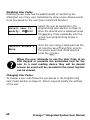
Removing User Codes
To remove a user code from the system but monitor if the user code
or card has been attempted to be used refer to Disabling User Codes
on Page 49. Follow the procedures below to remove a user number
and associated information or to re-assign the user number to
another user.
Select user to
modify: UN00010
48
Select the user as explained in the
Programming User Section on Page 41.
Once the desired user is displayed press
the
key.
Protege™ Integrated System User Manual
UN00010 Name
J Smith
UN00010 User
code: 1234
UN00010 Acs LvlÎ
Administration
UN00010 Facility
id: 0000000279
UN00010 Card
no: 0030497182
Once the user name is displayed clear
the name entry by pressing the
key.
Press the enter
key to move to the
User Code entry screen.
To clear the user code press the
key. Press the enter
key to save the
changes and move to the next
programming screen. This will prevent
pin number access using the user code.
Clear the access level setting to none by
pressing the
key. Press the enter
key to save the changes and move
to the next programming screen. Press
the enter
repeatedly until you are
at the facility code programming entry.
The display will show the users card
facility programming screen. Clear the
facility code by pressing
key and
then press enter to save the changes and
move to the next screen.
The display will show the users card
number programming screen. Clear the
card number by pressing
key and
then press enter to save the changes.
Repeat the above steps as required for other users.
Protege™ Integrated System User Manual
49
Disabling User Codes
Disabling a user code has the added benefit of monitoring the
attempted use of any user credentials by allow access denied events
to be processed for the user (User Code/Card Number).
Select the user as explained in the
Programming User Section on Page 41.
Once the desired user is displayed press
the
key. Press repeatedly until the
access level programming screen is
shown.
Select user to
modify: UN00010
UN00010 Access
None
Î
Once the user name is displayed use the
list selection keys
and
to scroll to
the access level none. Once selected
press the
key.
When the user attempts to use the User Code at an
LCD Keypad or presents the associated card for the
user to a card reading device they will be denied
access. An event will be recorded in the event log that
can be viewed.
Changing User Codes
To change a user code follow the procedures in the Programming
User Codes Section on Page 41. Where required modify the settings
of the user.
50
Protege™ Integrated System User Manual
6.0 ACCESS LEVELS
Access levels are used to define what Areas, Doors, Menus, Floors
and Elevators a group of users will be able to access and/or control.
An access level MUST be assigned to a user to allow them in to the
system. By default the Protégé System provides three default access
levels. The Protégé system supports up to 250 access levels.
6.1 MASTER ACCESS LEVEL
The master access level is a special access level that is not limited
and provides full access to all of the programmed system with the
exclusion of the Installer Menu.
The Master access level controls the ability for a
master user to login to the system. It is strongly
recommended not to change the Master access level
or other records that are programmed for the master
to operate correctly.
6.2 PROGRAMMING ACCESS LEVELS
Access levels should be programmed for groups of users, for example
administration, warehouse and management. Where the group can
clearly be identified by certain doors and functions that they need to
perform. This will ensure that access levels are managed effectively.
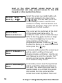
Programming Access Levels
Enter your [USER CODE] to logon to the keypad. Refer to the Logon
Keypad Section on Page 18.
In the example access level configuration access level
AC010 is being edited. Modifying the master access
Protege™ Integrated System User Manual
51
level or the other default access levels is not
recommended and may prevent access to the LCD
Keypad or other system functions.
Select the access level add/modify sub
menu item located in the main menu
[
, , ]. This will take you to the
screen asking to select a access level
number to modify. The first access level
number will be shown. The cursor will be
located over the first number.
Access level to
modify: AL001
The cursor will be positioned at the start
of the access level name entry. To
modify the name use the numerical keys.
Refer to the Text Entry Section on Page
12. Press enter
key to save the
name and move to the next
programming screen. Press the
key
to clear the name or to recall the current
name press the
key.
AL010 Name
Administration
AL010 Schedule
None
Î
AL010 SecondaryÎ
None
52
A schedule defines when this access level
will be valid. A setting of none will
disable schedule verification. Use the
and
keys to scroll the records. The
arrow Î on the top line indicates it is a
scroll selection entry screen.
A secondary access level if programmed
will be used if the assigned schedule is
not valid. This allows an access level to
operate based on a certain time period
and outside the time period another
access level used. By default this is set
Protege™ Integrated System User Manual
to None and is disabled if a schedule of
none is programmed. Use the
and
keys to scroll the records. The arrow Î
on the top line indicates it is a scroll
selection entry screen.
An example of the secondary access level function
would be for the administration access level to
require that the administration staff have a different
access level after hours. Setting the schedule and
then programming a secondary access level will
facilitate this operation.
AL010 Arm Grp
None
Î
AL010 Disarm GpÎ
None
The arming group defines which areas a
user assigned the access level will be
able to arm. A setting of none will disable
arming of an area. Use the
and
keys to scroll the records.
The disarming group defines which areas
a user assigned the access level will be
able to disarm. A setting of none will
disable arming of an area. Use the
and
keys to scroll the records.
An access level with a disarm group assigned will also
be able to arm the area in the disarm group.
AL010 Door Grp
None
Î
The door group defines which doors a
user assigned the access level will be
able to gain access. A setting of None will
prevent a user assigned the access level
from being able to unlock any doors. Use
the
and
keys to scroll the records.
Protege™ Integrated System User Manual
53
AL010 Menu Grp
None
Î
AL010 Elevator
None
Î
AL010 Floor GrpÎ
None
AL010 Misc
[********]
The menu group defines which doors a
user assigned the access level will be
able to gain access. A setting of None will
prevent a user assigned the access level
from being able to unlock any doors. Use
the
and
keys to scroll the records.
The elevator group defines which
elevators a user assigned the access
level will be able to gain access. A setting
of None will prevent a user assigned the
access level from being able to use
elevators. Use the
and
keys to
scroll the records.
The floor group defines which floors a
user assigned the access level will be
able to gain access, a user must also be
assigned a valid elevator car group. A
setting of None will prevent a user
assigned the access level from being able
to unlock any floors. Use the
and
keys to scroll the records.
The display will show the option entry
screen for the miscellaneous options. An
option can be toggled on and off by using
the numerical keys
to
. To view the
options in text entry mode press the
key. Refer to Option Entry on Page 12.
(1) Activate PGM On Keypad Access
When enabled the PGM associated with the access level will be
activated when a user logs in to an LCD Keypad. The LCD keypad
54
Protege™ Integrated System User Manual
must also be programmed to activate an access level PGM (Installer
Option).
(2) Activate PGM On Reader Access
When enabled the PGM associated with the access level will be
activated when a user unlocks a door. The reader must also be
programmed to activate an access level PGM (Installer Option).
(3-8) Reserved Options
Do not alter reserved options.
AL010 Select
pgm: --000:00
AL010 PGM on
time: 00000 secs
The display will show the access level
PGM. This is activated based on option 1
and 2 of the miscellaneous options. This
option should not be modified and should
be configured by the installer.
The display will show the access level
PGM activation time. This time is used
when the PGM is activated. This option
should not be modified and should be
configured by the installer.
Protege™ Integrated System User Manual
55
7.0 MENU GROUPS
Menu Groups are used to define what Menus a user or LCD keypad
will be able to access and/or display. A Menu Group is assigned to an
access level, refer Access Levels Section on Page 51, to allow users to
access the menus enabled on an LCD Keypad. The Protégé system
supports up to 250 menu groups.
7.1 MASTER MENU GROUP
The master menu group is a special menu group that allows access to
all general functions with the exclusion of the Installer menus.
The Master access level controls the ability for a
master user to login to the system. It is strongly
recommended not to change the Master menu group
or other records that are programmed for the master
to operate correctly.
7.2 PROGRAMMING MENU GROUPS
Menu groups should be programmed so that they are used for groups
of users, for example administration, warehouse and management.
Where the group can clearly be identified by the menus they need to
access. This will ensure that when the menu group is assigned to an
access level it is easy to identify and manage.
Programming Menu Groups
Enter your [USER CODE] to logon to the keypad. Refer to the Logon
Keypad Section on Page 18.
In the example menu group configuration menu
group MG010 is being edited. Modifying the master
56
Protege™ Integrated System User Manual
menu group or the other default menu groups is not
recommended and may prevent access to the LCD
Keypad or other system functions.
Select the menu group add/modify sub
menu item located in the main menu
[
, , ]. This will take you to the
screen asking to select a menu group
number to modify. The first menu group
number will be shown. The cursor will be
located over the first number. Pressing
enter will take you to the name
programming screen of the selected
menu group.
Menu group to
modify: MG001
To modify the name use the numerical
keys. Refer to the Text Entry Section on
Page 12. Press enter
key to save
the name and move to the next
programming screen. Press the
key
to clear the name or to recall the current
name press the
key.
MG010 Name
Warehouse Menus
MG010 Schedule
None
Î
MG010 SecondaryÎ
None
The display will show the schedule
programming. A schedule defines when
this menu group will be valid. A setting
of none will disable schedule verification.
Use the
and
keys to scroll the
records. The arrow Î on the top line
indicates it is a scroll selection entry
screen.
The display will show the secondary
menu group selection. A secondary menu
group if programmed will be used if the
Protege™ Integrated System User Manual
57
assigned schedule is not valid. This
allows an access level to be assigned
menu groups based on the time of the
day. By default this is set to None and is
disabled if a schedule of None is
programmed. Use the
and
keys to
scroll the records. The arrow Î on the
top line indicates it is a scroll selection
entry screen.
MG010 Main
[********]
The display will show the option entry
screen for the main menus that the
menu group will allow access to. An
option can be toggled on and off by using
the numerical keys
to
. To view the
options in text entry mode press the
key. Refer to Option Entry on Page 12.
(1) Area Control Menu
Setting the area control menu option allows the menu group to
access [
, ].
(2) User Programming Menu
Setting the user programming menu option allows the menu group to
access [
, ]. Some restrictions apply to the sub menus see sub
menu options.
(3) Event Review Menu
Setting the event review menu option allows the menu group to
access [
, ].
(4) Installer Menu
Setting the installer menu option allows the menu group to access
[
, ]. It is not recommended any menu groups other than the
installer menu group has this enabled.
(5) View Menu
Setting the view menu option allows the menu group to access
[
, ].
58
Protege™ Integrated System User Manual
(6) Time Settings Menu
Setting the time settings menu option allows the menu group to
access [
, ]. Some restrictions apply to the sub menus of the
time settings. Refer to the Sub Menu Options Section on Page 60.
(7) Bypass Zones Menu
Setting the bypass zones menu option allows the menu group to
access [
, ]. Some restrictions apply to the sub menus of the
bypass zone settings. Refer to the Sub Menu Options Section on Page
60.
(8) System Menu
Setting the system menu option allows the menu group to access
[
, ].
MG010 Sub
[********]
The display will show the option entry
screen for the sub menus that the menu
group will allow access to. An option can
be toggled on and off by using the
numerical keys
to
. To view the
options in text entry mode press the
key. Refer to Option Entry on Page 12.
(1) Installer Advanced Menu
Setting the sub menu option installer advanced menu option allows
the menu group to access [
, , ] and the sub menus.
(2) Extra Time Menus
Setting the sub menu option extra time menus allows the menu
group to access [
,
, - ] for programming schedules,
holidays and daylight savings.
(3) Bypass Trouble Zones Menu
Setting the bypass trouble zones menu option allows the menu group
to access [
, , ] and bypass system trouble zones.
(4) Allow Area Group Control
When enabled the user will be able to press the
right arrow key
and access area groups from the keypad.
(5) 24HR Area Control
Protege™ Integrated System User Manual
59
When enabled the user will be able to press the
left arrow key and
access the 24 hour section of areas from the keypad.
(6) Stay Arming Enabled
Setting the stay arming option allows a user to stay arm an area. An
area must be enabled for stay arming. Refer to Stay Arming Section
on Page 32.
(7) Force Arming Enabled
Setting the force arming option allows a user to force arm an area.
An area must be enabled for force arming. Refer to Force Arming
Section on Page 34.
(8) Reserved Option
Option 8 is reserved and should not be modified.
MG010 Extra 1
[********]
The display will show the option entry
screen for the first extra menus that the
menu group will allow access to. An
option can be toggled on and off by using
the numerical keys
to
. To view the
options in text entry mode press the
key. Refer to Option Entry on
Page 12.
(1) Extra User Sub Menus
Setting the extra users sub menu option will allow the menu group to
access [
, , - ].
(2) Installer Menu Group
Setting the installer menu groups option will open the Installer
Trouble Zone when this menu group is used to login to a LCD keypad.
It is recommended that this option is only set for the installer menu
group and not modified.
(3) Show Greeting To User On Login
The show greeting to user option operates the same as the greeting
option for the user (Refer to the User Programming Section on Page
41) however this will be applied to all users who have this group in
60
Protege™ Integrated System User Manual
their access level. If this or the user option is set the display will
show a greeting.
(4) User Can Acknowledge Alarm Memory
The user can acknowledge memory option will allow users who are
assigned this menu group to their access level memory acknowledge
functions. If this or the user option is set the user will be able to
acknowledge memory.
(5) User Can View Alarm Memory
The user can view memory option will show alarm memory when they
login to users who are assigned this menu group. If this or the user
option is set the user will be shown memory on login.
(6-8) Reserved Options
Do not alter reserved options.
MG010 Extra 2
[********]
The display will show the option entry
screen for the second extra menus that
the menu group will allow access to. An
option can be toggled on and off by using
the numerical keys
to
. To view the
options in text entry mode press the
key. Refer to Option Entry on
Page 12.
(1-8) Reserved Options
All options in the Extra 2 entry screen are reserved and should not be
modified.
Once the menu group has been programmed to use the menu group
it must be assigned to an access level. Refer to Access Level
Programming on Page 51.
Protege™ Integrated System User Manual
61
8.0 AREA GROUPS
Area groups are used to define what areas/partitions a user will be
able to view, arm and disarm. An area group is assigned to an access
level (Refer to the Access Levels Section on Page 51) to restrict the
ability for a user to control an area or partition. The Protégé system
supports up to 250 area groups.
8.1 ALL AREAS GROUP
The all areas group is a special area group that allows access to all
areas within the system. The all areas group is assigned to the
master access level by default.
Changing the all areas group is not recommended as
it will restrict access to the areas used by the Master
Access Level.
8.2 PROGRAMMING AREA GROUPS
Area groups should be programmed so that they are used for a group
of users, for example administration, warehouse and management
where the groups can clearly be identified by the areas that they
need to view, arm and disarm.
Programming Area Groups
Enter your [USER CODE] to logon to the keypad. Refer to the Logon
Keypad Section on Page 18.
In the example area group configuration area group
AG010 is being edited. Modifying the all areas group
is not recommended.
62
Protege™ Integrated System User Manual
Select the area group add/modify sub
menu item located in the main menu
[
, , ]. This will take you to the
screen asking to select an area group
number to modify. The first area group
number will be shown. The cursor will be
located over the first number.
Area group to
modify: AG001
To modify the name use the numerical
keys. Refer to the Text Entry Section on
Page 12. Press enter
key to save
the name and move to the next
programming screen. Press the
key
to clear the name or to recall the current
name press the
key.
AG010 Name
Admin Areas
AG010 Schedule
None
Î
AG010 SecondaryÎ
None
The display will show the schedule
programming. A schedule defines when
this area group will be valid. A setting of
none will disable schedule verification.
Use the
and
keys to scroll the
records. The arrow Î on the top line
indicates it is a scroll selection entry
screen.
The display will show the secondary area
group selection. A secondary area group
if programmed will be used if the
assigned schedule is not valid. This
allows an access level to be assigned
area groups based on the time of the
day. By default this is set to None and is
disabled if a schedule of none is
programmed. Use the
and
keys to
scroll the records. The arrow Î on the
Protege™ Integrated System User Manual
63
top line indicates it is a scroll selection
entry screen.
AG010 Block 01
[********]
The display will show the option entry
screen for the first eight areas that
belong to the area group. An option can
be toggled on and off (including an area
in to the group) by using the numerical
keys
to
. To view the options in text
entry mode press the
key. Refer to
Option Entry on Page 12.
Depending on the number of areas that are available
in the system the number of programmable blocks of
areas will be restricted.
AG010 Block XX
[********]
64
The display will show the next block of 8
areas that belong in the group. Pressing
will move to the next entry until you
return to the area group selection
screen.
Protege™ Integrated System User Manual
9.0 DOOR GROUPS
Door groups are used to define what doors a user will be able to
access and/or control. A door group is assigned to an access level
(Refer to the Access Levels Section on Page 51) to restrict the ability
for a user to gain entry or exit to certain doors. The Protégé system
supports up to 250 door groups.
9.1 ALL DOORS GROUP
The All Doors group is a special door group that allows access to all
doors within the system. The All Doors group is assigned to the
master access level by default.
Changing the All Doors group is not recommended as
it will restrict access to the doors by the Master
Access Level.
9.2 PROGRAMMING DOOR GROUPS
Door groups should be programmed so that they are used for a group
of users, for example administration, warehouse and management
where the groups an clearly be identified by the doors that they need
to have access to.
Programming Door Groups
Enter your [USER CODE] to logon to the keypad. Refer to the Logon
Keypad Section on Page 18.
In the example door group configuration door group
DG010 is being edited. Modifying the All Doors group
is not recommended.
Protege™ Integrated System User Manual
65
Select the door group add/modify sub
menu item located in the main menu
[
, , , ] This will take you to the
screen asking to select a door group
number to modify. The first door group
number will be shown. The cursor will be
located over the first number.
Door group to
modify: DG001
The cursor will be positioned at the start
of the door group name entry. Refer to
the Text Entry Section on Page 12. Press
enter
key to save the name and
move to the next programming screen.
Press the
key to clear the name or
to recall the current name press the
key.
DG010 Name
Warehouse Doors
DG010 Schedule
None
Î
DG010 SecondaryÎ
None
66
The display will show the schedule
programming. A schedule defines when
this door group will be valid. A setting of
none will disable schedule verification.
Use the
and
keys to scroll the
records. The arrow Î on the top line
indicates it is a scroll selection entry
screen.
The display will show the secondary door
group selection. A secondary door group
if programmed will be used if the
assigned schedule is not valid. This
allows an access level to be assigned
door groups based on the time of the
day. By default this is set to None and is
disabled if a schedule of None is
programmed. Use the
and
keys to
Protege™ Integrated System User Manual
scroll the records. The arrow Î on the
top line indicates it is a scroll selection
entry screen.
DG010 Block 01
[********]
The display will show the option entry
screen for the first eight doors that
belong to the door group. An option can
be toggled on and off (including a door
into the group) by using the numerical
keys
to
. To view the options in text
entry mode press the
key. Refer to
Option Entry on Page 12.
Depending on the number of doors that are available
in the system the number of programmable blocks of
doors will be restricted.
DG010 Block XX
[********]
The display will show the next block of 8
doors that belong in the group. Pressing
will move to the next block of 8
doors until you return to the door group
selection screen.
Protege™ Integrated System User Manual
67
10.0 FLOOR GROUPS
Floor groups are used to define what floors a user will be able to
access and/or control when using elevators within your facility. A
floor group is assigned to an access level (Refer to the Access Levels
Section on Page 51) to restrict the ability for a user to gain entry to
certain floors. The Protégé system supports up to 250 floor groups.
10.1 ALL FLOORS GROUP
The All Floors group is a special floor group that allows access to all
floors within the system. The All Floors group is assigned to the
master access level by default.
Changing the All Floors group is not recommended as
it will restrict access to the floors used by the Master
Access Level.
10.2 PROGRAMMING FLOOR GROUPS
Floor groups should be programmed so that they are used for a group
of users, for example administration, legal department and
management where the groups can clearly be identified by the floors
that they need to have access to.
Programming Floor Groups
Enter your [USER CODE] to logon to the keypad. Refer to the Logon
Keypad Section on Page 18.
In the example floor group configuration floor group
FG010 is being edited. Modifying the All Floors group
is not recommended.
68
Protege™ Integrated System User Manual
Select the floor group add/modify sub
menu item located in the main menu
[
, , ]. This will take you to the
screen asking to select a floor group
number to modify. The first floor group
number will be shown. The cursor will be
located over the first number.
Floor group to
modify: FG001
FG010 Name
Legal Department
FG010 Schedule
None
Î
FG010 SecondaryÎ
None
The cursor will be positioned at the start
of the floor group name entry. To modify
the name use the numerical keys. Refer
to the Text Entry Section on Page 12.
Press enter
key to save the name
and move to the next programming
screen. Press the
key to clear the
name or to recall the current name press
the
key.
The display will show the schedule
programming. A schedule defines when
this floor group will be valid. A setting of
none will disable schedule verification.
Use the
and
keys to scroll the
records. The arrow Î on the top line
indicates it is a scroll selection entry
screen.
The display will show the secondary floor
group selection. A secondary floor group
if programmed will be used if the
assigned schedule is not valid. This
allows an access level to be assigned
floor groups based on the time of the
day. By default this is set to None and is
disabled if a schedule of None is
Protege™ Integrated System User Manual
69
programmed. Use the
and
keys to
scroll the records. The arrow Î on the
top line indicates it is a scroll selection
entry screen.
FG010 Block 01
[********]
The display will show the option entry
screen for the first eight floors that
belong to the floor group. An option can
be toggled on and off (including a floor
into the group) by using the numerical
keys
to . To view the options in text
entry mode press the
key. Refer to
Option Entry on Page 12.
Depending on the number of floors that are available
in the system the number of programmable blocks of
floors will be restricted.
FG010 Block XX
[********]
70
The display will show the next block of 8
floors that belong in the group. Pressing
will move to the next block of floors
until you return to the floor group
selection screen.
Protege™ Integrated System User Manual
11.0 ELEVATOR GROUPS
Elevator groups are used to define what elevators a user will be able
to access and/or control. A elevator group is assigned to an access
level (Refer to the Access Levels Section on Page 51) to restrict the
ability for a user to use certain elevators. For example service
elevators can only be used by service staff restricting them access to
the public elevators. The Protégé system supports up to 250 elevator
groups.
11.1 ALL ELEVATORS GROUP
The All Elevators group is a special elevator group that allows access
to all elevators within the system. The All Elevators group is assigned
to the master access level by default.
Changing the All Elevators group is not recommended
as it will restrict access to the elevators used by the
Master Access Level.
11.2 PROGRAM ELEVATOR GROUPS
Elevator groups should be programmed so that they are used for a
group of users, for example administration, legal department, butler
service, maintenance and management where the groups can clearly
be identified by the elevators that they need to access.
Programming Elevator Groups
Enter your [USER CODE] to logon to the keypad. Refer to the Logon
Keypad Section on Page 18.
Protege™ Integrated System User Manual
71
In the example elevator group configuration elevator
group EG010 is being edited. Modifying the all
elevators group is not recommended.
Select the elevator group add/modify sub
menu item located in the main menu
[
, , ]. This will take you to the
screen asking to select an elevator group
number to modify. The first elevator
group number will be shown. The cursor
will be located over the first number.
Elevator grp to
modify: EG001
The cursor will be positioned at the start
of the elevator group name entry. To
modify the name use the numerical keys.
Refer to the Text Entry Section on Page
12. Press enter
key to save the
name and move to the next
programming screen. Press the
key
to clear the name or to recall the current
name press the
key.
EG010 Name
Service Team
EG010 Schedule
None
Î
EG010 SecondaryÎ
None
72
The display will show the schedule
programming. A schedule defines when
this elevator group will be valid. A setting
of None will disable schedule verification.
Use the
and
keys to scroll the
records. The arrow Î on the top line
indicates it is a scroll selection entry
screen.
The display will show the secondary
elevator group selection. A secondary
elevator group if programmed will be
used if the assigned schedule is not
Protege™ Integrated System User Manual
valid. This allows an access level to be
assigned elevator groups based on the
time of the day. By default this is set to
None and is disabled if a schedule of
None is programmed. Use the
and
keys to scroll the records. The arrow Î
on the top line indicates it is a scroll
selection entry screen.
EG010 Block 01
[********]
The display will show the option entry
screen for the first eight elevator cars
that belong to the elevator group. An
option can be toggled on and off
(including an elevator car into the group)
by using the numerical keys
to . To view the options in text entry
mode press the
key. Refer to Option
Entry on Page 12.
Depending on the number of elevator cars that are
available in the system the number of programmable
blocks of elevators will be restricted.
EG010 Block XX
[********]
The display will show the next block of 8
elevator cars that belong in the group.
Pressing
will move to the next block
of elevator cars until you return to the
elevator car group selection screen.
Protege™ Integrated System User Manual
73
12.0 TIME SETTING
Setting the date, time and day of the week is accessed through the
time menu [
, , ].
Setting the Date and Time
Enter your [USER CODE] to logon to the keypad. Refer to the Logon
Keypad Section on Page 18.
Select the date and time menu item
located in the main menu [
, , ].
This will display the time. Use the
numerical keys to enter the time
pressing
to move to the date entry
screen.
Enter system
time: 14:29
Enter system
date: 18/10/2005
Day of Week
Monday
74
Î
The display will show the date entry. Use
the numerical keys to enter the date
pressing
to move to the day of the
week entry screen and save the date
setting.
The display will show the current day of
the week. Use the
key to scroll up and
the
key to scroll down. Press
to move forward to the time entry. Press
to return to the menu or
to
exit.
Protege™ Integrated System User Manual
13.0 SCHEDULES
Schedules are used to perform functions based on a time period (up
to 4) and days of the week. You can also prevent a schedule from
occurring based on a holiday setting. Schedules are accessed through
the time menu [
, , ].
Programming Schedules
Enter your [USER CODE] to logon to the keypad. Refer to the Logon
Keypad Section on Page 18.
Schedule to
modify: 010
SC010 Name
*Schedule
Outside
Sign
010
SC001 Start
P1 Time: --:--
Select the schedule menu item located in
the main menu [
, , ]. This will
prompt you for a schedule to modify with
the first schedule that is available being
shown.
The cursor will be positioned at the start
of the schedule name entry. To modify
the name use the numerical keys. Refer
to the Text Entry Section on Page 12.
Press enter
key to save the name
and move to the next programming
screen. Press the
key to clear the
name or to recall the current name press
the
key.
The display will show the first period
start entry. Enter the time that you want
the period to start on. Press
to clear
the entry to --:--.
Protege™ Integrated System User Manual
75
SC001 End
P1 Time: --:--
SC010 P1 Days
[********]
SC010 P1 Hols
[********]
The display will then move to the first
period end entry. Enter the time that you
want the period to end on. Press
to
clear the entry to --:--.
The display will show the option entry
screen for the days that period one will
be active on. An option can be toggled
on and off (enabling the day) by using
the numerical keys to . To view the
options in text entry mode press the
key. Refer to Option Entry on Page 12.
The display will show the option entry
screen for the holiday groups that period
one will be active on. An option can be
toggled on and off (enabling the schedule
to be active on the holiday group) by
using the numerical keys to . To view
the options in text entry mode press the
key. Refer to Option Entry on Page
12. Option 1 to 8, are assigned Holiday
Group 1 to 8.
If a holiday is active and a period in a schedule is NOT
programmed with the holiday group the schedule will
not be valid. If a schedules period is to operate on a
holiday the period must have at least one of the
holiday group options programmed that matches the
holiday setting.
The above sequence is repeated for Period 2 until Period 4. Once
Period 4 has been programmed you will be returned to the schedule
selection screen.
76
Protege™ Integrated System User Manual
View Schedule Status
To view the current status of a schedule press the
key while in
the schedule selection screen. The schedule status screen will be
shown.
Select the schedule using the
or
Schedule to
keys. Press the
key to view the
modify: 010
schedule status.
S: VSE
Y--
The display will show the schedule
status. If a 'Y' is under the 'V' the
schedule is valid. If a 'Y' is under the 'S'
or 'E' the start or end time are valid.
Protege™ Integrated System User Manual
77
14.0 HOLIDAYS
Holidays are used to prevent a schedule from operating during a
predefined holiday period. A holiday can be programmed to be a
single day or a period from start until end. To make a holiday repeat
the holiday can be programmed with a blank entry for the year.
Holidays are accessed through the time menu [
, , ].
Programming Holidays
Enter your [USER CODE] to logon to the keypad. Refer to the Logon
Keypad Section on Page 18.
Select the holiday menu item located in
the main menu [
, , ]. This will
prompt you for a holiday to modify with
the first holiday that is available being
shown.
Holiday to
modify: 010
HL010 Start
Date: --/--/----
HL010 End
Date: --/--/----
The display will show the start date
entry. Enter the date that you want the
holiday to start on. Press
to clear the
entry to --:--.
The display will then move to the holiday
end date entry. Enter the date that you
want the holiday to end on. Press
to
clear the entry. Program the same date
as the start date for a holiday that is
valid for one day.
To make a holiday repeat leave the year
section set to ----.
78
Protege™ Integrated System User Manual
HL010 Hol Group
[********]
The display will show the option entry
screen for the holiday groups that this
holiday will enable when the holiday is
active. These will be masked with the
holiday group in the schedule. An option
can be toggled on and off (enabling
holiday group number) by using the
numerical keys
to . To view the
options in text entry mode press the
key. Refer to Option Entry on Page
12. Option 1 to 8, are assigned Holiday
Group 1 to 8.
If a holiday is active and a period in a schedule is NOT
programmed with the holiday group the schedule will
not become valid. If a schedules period is to operate
on a holiday the period must have at least one of the
holiday group options programmed that matches the
holiday setting.
View Holiday Status
To view the current status of a holiday press the
key while in the
holiday selection screen. The holiday status screen will be shown.
Holiday to
modify: 010
Select the holiday using the
and
keys. Press the
key to view the
holiday status.
S: V G: 12345678
Y
------Y-
The display will show the holiday status.
If a 'Y' is under the 'V' the holiday is
valid. If a 'Y' is under the 'S' or 'E' the
start or end time are valid.
Protege™ Integrated System User Manual
79
15.0 DAYLIGHT SAVINGS
Daylight savings settings are used to configure the rules associated
with processing time changes for daylight savings in your country.
The daylight savings rules are provided to match the international
UTC daylight savings rules. The daylight savings configuration is
accessed through the time menu [
,
, ].
Programming Daylight Savings
Enter your [USER CODE] to logon to the keypad. Refer to the Logon
Keypad Section on Page 18.
D/S Starts On
1st Sunday
Î
Select the daylight savings menu item
located in the main menu [
,
, ].
This will prompt you for the starting rule
for daylight savings. Use the
and
keys to change the start day rule.
D/S Start MonthÎ
October
The starting rule for daylight savings also
requires the month to be set. Use the
and
keys to change the start month
rule setting.
D/S Ends On
Last Sunday
Î
This will prompt you for the ending rule
for daylight savings. Use the
and
keys to change the end day rule.
D/S End Month
March
Î
80
The ending rule for daylight savings also
requires the month to be set. Use the
and
keys to change the end month
rule setting.
Protege™ Integrated System User Manual
D/S Options
[********]
The display will show the option entry
screen for the daylight savings. Options
for daylight savings are currently
reserved and should not be modified
from the default value.
Daylight savings will activate at 2:00 AM on the
morning of the rule becoming active and either
increment or decrement the time accordingly. An
event will be logged indicating that the time has been
changed by a daylight saving operation.
Protege™ Integrated System User Manual
81
16.0 SPECIAL FEATURES
The Protégé System offers many flexible features to enhance the
management of your installation.
16.1 OFFLINE MENU ACCESS
Offline menu options are provided to allow access to certain functions
without the need to log in to the LCD Keypad. Pressing the [
] key
while logged out will allow you view the offline menu.
The offline menu options must be enabled by your
security professional. Refer to the configuration
section.
Automation Menu
To control automation points press [
, ] while logged out. The
screen will display the first automation point.
Warehouse Lights
is OFF
Use the
and
keys to change the
displayed automation point. Press the
key to turn the point on for the
timed period,
key to turn the point off
or
key to latch the point on.
Trouble View
To view troubles from the offline menu press [
, ] while logged
out. The screen will show the trouble display. Refer to Trouble View
Section on Page 21.
82
Protege™ Integrated System User Manual
Event View
To view events from the offline menu press [
, ] while logged
out. The screen will show the event display. Refer to Viewing Event
Information on Page 39.
Information Menu
To view system information press [
, ] while logged out. The
screen will display the first line of information with the address of the
LCD Keypad that you are logged in to.
Info at KP039
Ver: 1.04.1371
Use the
and
keys to change the
display information. The first display will
show the System Controller application
version, 1.04 build 1371. This will vary
depending on the version installed.
Info at KP039
Bios: 1.04.1371
Pressing the
key will show the BIOS
Application Version Number, 1.02 Build
0375.
Info at KP039
Boot: 1.04.0176
Pressing the
key will show the BOOT
Application Version Number, 1.04 Build
0176.
Info at KP039
Database: 1.09
Info at KP039
Serial: 2AF7139B
Info at KP039
Memory: 512KB I
Pressing the
key will show the
Database Version Number, 1.09.
Pressing the
key will show the serial
number of the hardware.
Pressing the
key will show the
current memory capacity that is available
Protege™ Integrated System User Manual
83
on board. The letter following the
memory size will indicate the location of
the memory that is in use. This will be
blank or 'I' for internal and 'E' for
extended.
Info at KP039
Time: 09:50
Pressing the
key will show the
current time setting in the internal real
time clock.
Info at KP039
Date: 24/04/2004
Pressing the
key will show the
current date setting in the internal real
time clock.
Info at KP039
Day: Tuesday
Pressing the
key will show the
current day of the week that is set in the
real time clock.
Pressing the [
] arrow again will return to the first screen showing
the application version number.
16.2 OFFLINE DOOR UNLOCK
The Protégé provides a function key
that can be used to unlock a
door that is located near the keypad. This can be programmed to
unlock without the user logging in or from the main menu when the
user has logged in.
The ability to unlock the door from the function key
must be enabled by your security professional or
property manager for more information refer to the
configuration section.
84
Protege™ Integrated System User Manual
16.3 DISABLE AUDIBLE OUTPUT
It may be desirable to disable the audible tone on your keypad. This
will prevent the beeper from generating any notification of alarms,
exit delay or entry delay. The keypad will not generate a tone when a
key is pressed and audible confirmation will be turned off.
Disabling Audible Output
1. Press and hold the clear
key.
2. Keypad will generate one long audible tone (rejection tone) to
signify that the audible output is disabled.
Enabling Audible Output
To enable the audible output repeat the above steps, the keypad will
generate four audible tones to indicate that the audible output has
been enabled.
The ability to disable the audible tone is a
configuration option and must be enabled by your
security professional. Refer to the configuration
section.
16.4 MESSAGES
The Protégé system provides powerful message handling capabilities
to allow messages to be sent to the keypads within an installation
from the Protégé System Management Suite or Programmable
Function. A new message that has been sent to your system is
announced by an audible tone and the message will be displayed on
the keypad.
Clearing Messages
1. Message text is displayed on the LCD display screen.
2. To acknowledge and clear the display message press the
key.
Protege™ Integrated System User Manual
85
16.5 PANIC ALARM
The Protégé system can provide three panic alarms that can
immediately generate an alarm after simultaneously pressing and
holding two specific buttons for three seconds. Based on your needs,
these panic alarms can generate audible alarms (sirens or bells) or
silent alarms and can communicate specific messages to your
monitoring station or property manager.
Press & hold keys
Press & hold keys
Press & hold keys
and
and
and
for the panic alarm.
for a medical alarm.
for a fire alarm.
All Panic Alarm activations MUST be enabled by your
property manager or installation company. Please
refer to the System Configuration Section on Page 88.
16.6 FIRE ALARM
When a fire alarm occurs, the LCD User Station will emit three
audible tones at 2 second intervals until reset by entering a valid user
code. If the zone is a delay fire zone, there is a delay of thirty
seconds before the system contacts the security company or property
manager.
A delayed fire zone will prevent unnecessary reporting of false alarms
allowing you to reset the fire alarm before a report is sent. If there is
no fire condition, contact your property manager or security company
immediately to avoid an unnecessary response.
A delayed fire zone will automatically cancel if the smoke detector is
reset within 30 seconds. Pressing any key on the keypad during the
first 30 seconds will silence the alarm for 90 seconds.
86
Protege™ Integrated System User Manual
Fire Alarm functions MUST be enabled by your
security professional or installation company. Please
refer to the System Configuration Section on Page 88.
16.6 SMOKE DETECTOR RESET
When a fire alarm occurs depending on the installation it may be
required to generate a smoke detector reset. To reset smoke
detectors from a keypad press the
and
key together for 3
seconds.
Protege™ Integrated System User Manual
87
17.0 CONFIGURATION
The Protégé system has many options that are enabled by your
installer. The following lists the general options and how your system
is configured.
17.1 ZONE DESCRIPTION
The following lists the common zones in your system and how each
zone is configured. For a complete zone list consult your security
professional or property manager.
ZONE NAME
88
FORCE
STAY
BYPASS
Protege™ Integrated System User Manual
17.2 FIRE ZONE
The following lists the fire zone configuration for your system.
Enabled Disabled
Fire Zone
Delayed Fire Zone
Smoke Detector Reset
Your fire zones are located on zone(s) ________________ and
operate with a delay of _____ seconds. You can perform a smoke
detector reset on keypad(s) __________________.
17.3 ARMING MODES
Your user code will provide you access to ________________ and
you will be able to perform the arming functions below on your areas.
Enabled Disabled
Regular Arming
Stay Arming
Force Arming
Instant Arming
17.4 PANIC KEYS
The following lists the panic key configurations that are enabled on
your system.
Enabled Disabled
[1] + [3] Panic Alarm
[4] + [6] Medical Alarm
[7] + [9] Fire Alarm
Protege™ Integrated System User Manual
89
17.5 OFFLINE MENU ACCESS
The keypad(s) __________________ are enabled for offline access
and are programmed with the following options.
Enabled Disabled
Automation Control
Trouble View
Events
System Information
17.6 OFFLINE FUNCTION CONTROL
The keypad(s) __________________ have the door function key
enabled and will unlock door _____________________.
Enabled Disabled
Door Unlocks Offline
Door Unlocks At Main Menu
17.7 TIMERS
Your entry time is programmed to be ____ seconds. This is the time
that you have before an alarm is generated if you enter through the
zone __________________ __.
Your exit time is programmed to be ____ seconds. This is the time
that you have to exit before the system arms.
If an alarm occurs the siren will activate for _____ minutes unless
disarmed.
90
Protege™ Integrated System User Manual
17.8 USERS
The following table should be used to keep a record of the users
programmed in your Protégé system. Record the name of the user
only. Do not write the user code.
NUMBER
USER NAME
ACCESS LEVEL
UN00001
UN00002
UN00003
UN_____
UN_____
UN_____
UN_____
UN_____
UN_____
UN_____
UN_____
UN_____
UN_____
MASTER
INSTALLER
DEMO
_____
_____
_____
_____
_____
_____
_____
_____
_____
_____
MASTER__________
INSTALLER________
DEMO____________
_________________
_________________
_________________
_________________
_________________
_________________
_________________
_________________
_________________
_________________
Protege™ Integrated System User Manual
91
18.0 WARRANTY
The Seller warrants its products to be free from defects in materials
and workmanship under normal use for a period of one year. Except
as specifically stated herein, all express or implied warranties
whatsoever, statutory or otherwise, including without limitation, any
implied warranty of merchantability and fitness for a particular
purpose, are expressly excluded. The Seller does not install or
connect the products and because the products may be used in
conjunction with products not manufactured by Seller, Seller cannot
guarantee the performance of the security system. Seller's obligation
and liability under this warranty is expressly limited to repairing or
replacing, at Seller's option, any product not meeting the
specifications. In no event shall the Seller be liable to the buyer or
any other person for any loss or damages whether direct or indirect
or consequential or incidental, including without limitation, any
damages for lost profits, stolen goods, or claims by any other party
caused by defective goods or otherwise arising from the improper,
incorrect or otherwise faulty installation or use of the merchandise
sold.
logo are registered trademarks of
Protégé® and the
Integrated Control Technology Limited.
92
Protege™ Integrated System User Manual