1
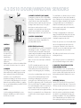
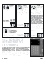
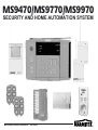
MS9470/MS9770/MS9970
SECURITY AND HOME AUTOMATION SYSTEM
MS9470/MS9770/MS9970 MARMITEK
NICOSHOP
INTRODUCTION
Congratulations! You purchased a Marmitek Security System. Marmitek
Security Systems are quality products and are manufactured with high
precision.
The Marmitek Security System protects yourself and your home against
intruders. On top of that your Marmitek Security System can control lights
and appliances throughout your house (using the existing mains wires!). In
that way your Marmitek Security System can create a “lived-in look” when
you are away. Optional plug-in modules, wall switches or DIN-Rail modules
(at the distribution panel) allow switching of appliances or dimming of lights.
These modules can be programmed to be part of the alarm signalling.
Up to 16 wireless (radio) sensors can be installed onto the supplied Security
Console SC2800. This base station can be operated by up to 8 wireless
(radio) remote controllers. On top of that you can operate your Marmitek
Security System via the keyboard of the Security Console SC2800.
When an alarm situation occurs, the built-in telephone voice dialler of the
Security Console SC2800 will dial up to 4 pre-programmed telephone
numbers and play your pre-recorded alarm message. Anyone picking up the
CONTENTS
1.
General
3
2.
Safety Precautions
3
3. Marmitek Systems
3.1 Components
3.2 Important Features
4
4
4
4.
4.1
4.2
4.3
4.4
4.5
4.6
4.7
4.8
4.9
4.10
Installation of the components
Signals and range
SC2800 Security Console (base station)
DS10 Door/Window Sensors
MS10 Motion Sensors
KR21 Key Fob Remote Control
SH624 System Remote Control (optional for MS9470)
LM12 Lamp Module (optional for MS9470)
Installation of other (wired) sensors
Installation of the GB10 Glass Break Sensor
DigiMax 210 wireless thermostat (OPTION)
5. Programming the SC2800 base station
5.1 Registration of radio sensors
5.2 Registration of wireless remote controls
2
5
5
6
8
9
10
10
11
12
12
14
15
15
16
phone on the other end responds to the alarm message by pressing a single
digit on that telephone. This will stop further dialling and allows the person
who picked up the phone to “listen-in“ to the protected premises by means
of the built-in microphone of the Security Console SC2800. Failing sensors
will be reported in a similar way by playing a fixed service message.
It is important that you carefully read through all of the chapters of this
users’ guide before starting the installation. Also when a third party is
installing the system for you, you have to read this manual carefully as it
contains important information regarding operation and use of the
Marmitek SC2800.
In case of any problems during installation or use of the system, please read
first through the troubleshooting chapter in the back of this users’ guide.
You also can contact the Martmitek web site (marmitek.com) for additional
information. In case you cannot fix the problem with these
recommendations, you then have to contact the dealer where you
purchased your Marmitek Security System.
5.3
5.4
5.5
5.6
5.7
5.8
5.9
5.10
Set siren on/off (silent alarm)
Programming of telephone numbers
Recording the alarm message
Delayed alarm times
Jamming detection on/off
Change personal identification code (PIN)
Erasing a radio sensor
Erasing of all settings
16
17
18
19
20
21
22
22
6.
6.1
6.2
6.3
6.4
6.5
6.6
6.7
6.8
6.9
Operating the system
Install, Run 1 and Run 2
Arming the system
When an alarm situation occurs
Disarming the system
Disarming after an alarm (reset)
Panic alarm
Zone indicators
Controlling lights and appliances (Home Automation)
Lifestyle programming
23
23
23
24
25
25
26
26
27
29
7.
SC2800 dial-in features
30
8.
Setting ‘sensor error’ message
31
9.
Troubleshooting
32
MARMITEK
1 GENERAL
• Marmitek systems are designed for use in dry environments.
• Avoid placement of system components in environments with extreme temperatures (normal operation is 0-40°C) or humidity.
• Only the supplied PS500 Mains Adapter can be used to power the SC2800 base station and preferably alkaline batteries should be used for the sensors
and remote. Do not use rechargeable batteries!
• Marmitek equipment is CE approved, and has radio transmission approvals for most countries.
• Always carefully follow the instructions in the users’ guide.
2 SAFETY PRECAUTIONS
• There is a hazard of electrical shock or injury if the system (the PS500 in particular) is installed in any other way than recommended in this manual.
The electrical parameters, especially with respect to the mains voltage listed on the PS500, must be observed at all times.
• Only Marmitek Authorised Service Centres (MASC’s) are qualified to repair the system. Unauthorised opening of any parts of the system voids the warranty.
• It is highly dangerous to open the PS500 Mains Adapter as it contains parts carrying 230 V mains voltage. In case of malfunction of the PS500
Mains Adapter, unplug the system and contact your dealer.
MS9470/MS9770/MS9970
3
3 MARMITEK SYSTEMS
3.1 COMPONENTS
MARMITEK SYSTEMS CONSIST OF THE FOLLOWING PARTS:
1
SC2800 SECURITY CONSOLE (BASE STATION)
2
PS500 MAINS ADAPTOR*
3
MS10 MOTION SENSORS
4
DS10 DOOR/WINDOW SENSORS
5
KR21 KEY FOB REMOTE CONTROL
6
WALL MOUNTING BRACKET FOR SC2800*
SECURITY CONSOLE
7
SH624 SYSTEM REMOTE CONTROL
(OPTIONAL FOR MS9470)
8
LM12 LAMP MODULE (OPTIONAL FOR MS9470)
9
BREAKING GLASS DETECTOR (OPTIONAL)
1
4
3
5
10 SET OF ACCESSORIES: BATTERIES,
TELEPHONE CABLES (ANALOG AND ISDN),
WIRED SENSOR CABLE, EAR PHONE AND
INSTALLATION MATERIALS
*
9
8
7
NOT INCLUDED
3.2 IMPORTANT FEATURES
•
•
•
•
•
•
•
•
•
•
•
4
Up to 16 wireless sensors can be installed on the base station
Alarm and system messages can be sent to up to 4 different phone numbers
Anti jamming circuit detect interfering radio signals
The alarm message can be recorded by the user (up to 12 sec.)
Confirmation of the alarm message by pressing any key on a telephone (DTMF)
“Listen-in” to the protected premises when an alarm is reported
Silent alarm function (siren disabled)
Lifestyle function perfectly simulates presence of residents
Input for wired sensor (smoke or flood detector)
Additional sirens and lights can be activated over mains wires (plug and play)
Automatic activation of lights and appliances when leaving or upon arrival
MARMITEK
4 INSTALLATION OF THE COMPONENTS
4.1 SIGNALS AND RANGE
Your security system is using various
communication techniques. For a good
understanding of these, it is recommended to
read through the short explanation given below.
Wireless:
The sensors (DS10 Door/Window Sensor, MS10
Motion Sensor, etc.) and remote controllers, are
communicating wirelessly via radio signals with
the base station. This has the great advantage
that no wires need to be installed between
sensors and base station. Moreover, you simply
can take the Marmitek system with you in case
you’re going to move. Built-in transmitters in the
sensors and remotes and a receiver in the base
station take care of this wireless communication.
The ultra high frequencies (UHF) of the
transmitters make sure that the signals go
through walls and ceilings.
The range (maximum distance between
transmitters and base station) depends on local
circumstances. I.e. a brick wall will give more
attention of the signal than a dry wall. Building
materials with metal foil can greatly influence the
range. Another reason for reduced range is that
other transmitters are in use in the building,
operating on the same frequency. Especially
wireless (radio) headsets and speakers can
influence the range of the sensors and remotes.
Cordless phones do not influence the range of the
system. Switching power supplies (e.g. used for
halogen lamps, CFL lamps, PC’s) can influence the
range of the system also. The base station is
equipped with a system to detect strong
interfering signals (refer to chapter 5.7 Set anti
jamming detection on/off).
You do not have to worry that these frequencies
will influence the alarm functions of the system or
initiate an alarm. The signals from the sensors are
encrypted in such a way that, after installation,
the base station only will recognise these as valid
MS9470/MS9770/MS9970
messages and ignore interfering signal from
mobile phones, wireless headsets, other security
systems, etc.
Over existing mains wiring:
Controlling lamp modules and other Home
Automation modules is done over existing mains
wiring. The PS500 Mains Adapter transmits socalled Marmitek X-10 signals coming from the
Security Console SC2800 onto the mains wiring,
whereby a message containing an address
(consisting of a so-called house and unit code)
and an instruction (e.g. on or off) are transmitted
to e.g. a lamp module.
These signals are transmitted over all mains
wiring, regardless of the fuse circuit, as long as
these are connected to the same phase. In case
you want to transmit the signals over multiple
phases, you’ll have to install a so-called phase
coupler in your installation, preferably at the
distribution panel. (more information available
through your dealer or at www.marmitek.com).
Some extra sirens (PH7208) are addressed in the
same way.
Via telephone line:
When an alarm is triggered by one of the sensors
or a technical malfunction occurs, an alarm or
system message will be transmitted over the
phone line connected the Marmitek system, to the
persons (friends or family) of which you have
programmed the telephone number into the
system. For this reason, the base station will be
connected to the telephone line with the supplied
cable and plug/adapter (this may be country
specific).
During an alarm situation, an eventual telephone
call will be disconnected.
In case of a analog PABX with multiple telephones:
Connect the SC2800 base station directly to the
incoming phone line (i.e. before the PABX).
In general you’ll need to dial a “0” or a “9” to get
an outside line. You need to program this number
together with the rest of the phone number you
want the base station to dial when an alarm
occurs (refer to 5.4).
In case of and ISDN or other digital telephone
connection:
The SC2800 can never be connected directly to
an ISDN or other digital phone line. You have to
connect the SC2800 base station to an analog
adapter with the supplied ISDN cable. In case no
analog input is available, you have to purchase an
adapter (ask you telecom supplier). In general
you’ll need to dial a “0” or a “9” to get an outside
line. You need to program this number together
with the rest of the phone number you want the
base station to dial when an alarm occurs (refer to
5.4). Please keep in mind that in case of loss of
mains power, an ISDN PABX will not allow the
SC2800 to dial out. This can only be guaranteed
when using an analog telephone line.
In case of a single analog telephone connection:
Insert the plug/adapter/cable combination,
coming from the SC2800 base station, into the
telephone outlet and insert the plug of your
regular phone into this plug/adapter combination.
5
4.2
THE SC2800
BASE STATION
1. PANIC
When pressed, this red button initiates an
immediate alarm.
2. ARM HOME
Alarm function when being at home. Only door
and window sensors (no motion sensors) are
activated.
12
1
6
13
2
9
3
7
14
8
15
4
16
5
10
11
17
3. ARM AWAY
All sensors are activated.
4. BYPASS
When you want to arm the system and one of the
sensors is reporting a problem (e.g. window is still
open, battery low, etc.), you can choose to arm
the system without activating this particular
sensor. As long as you can hear the dual error tone
error, you have the option to press the “bypass”
button and arm the system again. The zone
indicator of that sensor is now flashing rapidly.
Once the error condition is corrected (e.g.
window closed), the bypass will be automatically
removed and the sensor becomes part of the
total system again.
5. DISARM
Disarms the system after entering your personal
identification code (PIN).
6. SYSTEM INDICATORS
RECORD – Lights when during recording and
playing the personal security message.
JAMMING- Indication that a strong interfering
signal is detected.
ARM- Lights when the system in armed.
BATTERY LOW- Indication that the back up battery
of the base station needs to be replaced.
POWER- Indication for proper operation of the
PS500. Lights during normal operation.
6
23
18
19
20
7. KEYBOARD
To program and operate the security system.
8. UNIT ON/UNIT OFF
For operating Marmitek X-10 Home Automation
Modules (like LM12 Lamp Module). Enter the unit
code of the module on the keyboard. Then use
this key to switch this module on or off.
9. BRIGHT/DIM
For controlling the brightness of lights connected
to a specific lamp module. Enter the unit code of
the module on the keyboard and then use this key
to brighten or dim the lights.
10. ALL LIGHTS ON/OFF
To switch on all lamp modules in the system or to
switch off all modules (lamp and appliance
modules), regardless the address.
21
22
11. MICROPHONE
Very sensitive microphone for:
• recording a personalised alarm message
• “listen-in” to the protected premises via the
telephone line during an alarm situation
12. RUN 1, RUN 2, INSTALL, THERM SWITCH
RUN 1 – For normal alarm operation.
RUN 2 – For normal alarm operation. When in
disarmed mode, the base station will give a
pleasant sounding tone when a door or window is
opened (access control).
INSTALL – Position for installing sensors and for
changing system settings.
THERM - For use with Marmitek X-10 Wireless
Thermostats. Thermostat functions are
described in the manual of the thermostat.
MARMITEK
13. ENTER
Used for confirmation of the system settings
during installation.
14. TIME OFF
Used to set the Lifestyle mode. When pressing this
key at a certain time, the Lifestyle program will be
switched off every day at that specific time (refer
to 6.9).
15. RECORD
Used for recording and replaying of the alarm
message during installation.
16. ZONE 9-16
Used for switching from zone-indicators 1-8 to
9-16.
17. ZONE-INDICATORS
These indicators give the status of each installed
zone. Each zone represents one sensor.
18. WIRED SENSOR/EARPHONE JACK
This input jack has two functions:
You can listen to the recorded alarm message
during installation.
A wired sensor can be connected to this input
(refer to 4.8).
19. SIREN
In case of an alarm this siren gives a piercing
warning signal with a 95dB sound pressure level.
The siren can be switched of if required (silent
alarm). The system allows control of multiple
sirens over regular power lines.
N.B.: Volume and tone can be damaging for your
hearing when you are too close to the siren when
activated.
20. BATTERY COMPARTMENT
This compartment holds the 9 V back-up battery.
This battery keeps the system fully operation in case
of mains power failure. All setting will remain in
memory because these are store in an non volatile
(EEPROM) memory. Use preferably an alkaline
battery (no rechargeable battery). When you are
disconnecting the system on purpose for a longer
period of time, you must disconnect this battery to
avoid unnecessary discharge of this battery.
MS9470/MS9770/MS9970
21. TELEPHONE CONNECTION
For connecting the system to the telephone line
(meant for analog lines; for ISDN and PABX, refer
to 4.1). Always use the supplied cable.
22. CONNECTION MAINS ADAPTOR
Connect the supplied PS500 Mains Adapter. Use
only the supplied PS500.
23. ANTENNA
Used for reception of radio signals of sensors and
remote controls. Can be mounted horizontally
(tabletop use) or vertically (wall mounted).
INSTALLATION:
Choose a suitable place for the base station, close
to a power outlet. (230VAC) and a telephone
socket.
For maximising the range, it is recommended to
place the base station as much as possible in the
middle of the premises you want to protect. By
doing this you use the smallest possible distance
between sensors and base station and optimise
the range of the system.
mounting hole and reposition the plastic tube
over the antenna wire.
CONNECTING THE PS500 MAINS ADAPTER
Connect the DIN plug into the socket at the back
of the base station. Plug the mains adapter PS500
into a 230 V wall outlet.
PLACING OF THE BACK-UP BATTERY
Open the battery compartment at the back of the
base station. Connect the 9 V block battery
observing the correct polarity. Place the battery in
the compartment and close the battery cover.
N.B: The back-up battery has a limited capacity,
which will be used as soon as PS500 mains
adapter does not supply the base station
anymore. Be aware of this when disconnecting
the PS500 on purpose.
CONNECTING TELEPHONE CABLE
Connect the supplied telephone cable to the back
of the base station. Connect the telephone plug
in your telephone wall socket. (refer to 4.1 for
more information on ISDN and PABX connection).
In doing so you have to keep in mind:
1. Avoid placing the base station close to large
metal objects (heater, cooker, etc.)
2. That the place is easy to reach
3. The base station is not placed close to a PC or TV.
TABLE TOP USE
You can position the base station on any flat
surface (table, console, etc.) or use the bracket for
wall mounting. The rubber feet make sure that
the base station remains in its position.
WALL MOUNTING
The supplied wall-mounting bracket allows you to
install the SC2800 base station vertically against a
wall. Mount the SC2800 at such a height that you
can view and operate the panel easily.
For wall mounting, you have to install the radio
antenna in the vertical position. Carefully pull the
plastic tube away from the antenna wire. Then
pull the antenna wire through the vertical7
4.3 DS10 DOOR/WINDOW SENSORS
6
1
2
5
CONTROLS:
3
1. CONTROL
INDICATOR
When you press
the button TEST, or
when the unit is
transmitting a
signal to the base
station, this
indicator will come on. When the indicator blinks
only weakly, the batteries have to be replaced.
2. MIN/MAX
For setting a delay time of approx. 30 seconds.
When switched to the MAX position, the delay
time is activated. Position the DELAY switch
behind the cover to the MIN position
(instantaneous alarm). For an entrance door you
set the switch to MAX, allowing you to enter and
disarm the system When you want e.g. a garden
door to respond immediately, you switch the DS10
to the MIN position.
3. TEST
Used for activating and installing the sensor
during the installation procedure. Can also be
used to test the sensor.
8
4. MAGNETIC CONTACTS (NOT SHOWN)
The magnetic contacts are of the NC (Normally
Closed) type. The distance between magnet and
contact can not be more than 5mm. When
mounted, you have to make sure that the arrows
on magnet and contact line up. The length of
wire between contact and sensor can be
expanded or shortened. Make sure that the wires
are well connected and the screws tightened.
Multiple magnet switches can be placed in series.
5. BATTERY COMPARTMENT
Place 2 pieces AA batteries observing the polarity
instructions in the battery compartment. Use
preferably alkaline batteries.
INSTALLATION (install mode):
The Door/Window Sensor consists of a transmitter
and a magnetic contact. The magnetic contact
consists of 2 parts: the wired NC contact and a
separate magnet. Normally the magnet will make
the contact to close. When opening of a door or
window, the contact be opened and a message
will be sent to the base station (the red indicator
will come on).
The DS10 is primarily meant for doors and
windows, whereby the transmitter part and
contact will be placed on the frame and the
magnet on the moving part (door or window).
Look on door or window frame where the sensor
can be positioned without running the risk of
obstructing or damaging the sensor when
opening this door or window. Position the sensor,
if possible, as high up as possible. This will result in
the best possible range. Then mark the position of
the sensor and magnet contact. Do not place the
magnet contact directly on a metal surface. In
case of a metal or metal enforced plastic windowframe, it is recommended to use a 5mm wooden
or plastic isolator between magnet contact and
frame.
For metal frames, the distance between contact
and magnet can not be more than 3mm when
door or window is in closed position. For wooden
frames this distance is 8mm, but in all cases the
opening should be kept to the minimum. To
mount the transmitter part, you remove the
batteries and screw the back of the transmitter
onto a suitable background.
For lift-up or sash windows, the contact and
magnet should NOT slide along each other, but
should be positioned in such a way that they
clearly move away from each other.
Remove the protective cover of the double-sided
tape on the magnet and position this on the
opening part of window or door. Remove the
protective cover of the double-sided tape on the
contact and position this on the frame.
N.B.: Make sure that the arrows on the contact
and magnet line up.
After testing the system, it is recommended to
also screw down the magnet on the surface.
6. MOUNTING THE ANTENNA OF EXTRA
DOOR/WINDOW SENSORS
Extra door/window sensors are supplied with a
wire antenna and a separate antenna tube. For
proper operation, slide the plastic tube over the
antenna wire and push it firmly into the sensor
housing.
ACTIVATING THE DS10
Push the TEST key of the DS10 for more than 1
second; the indicator blinks twice. Then press the
TEST key once more and close the battery cover.
N.B.: When replacing the batteries of the sensor
when the system is operational, you can make
sure that the sensor maintains its unique code
avoiding re-installation. To do this, you OPEN the
door or window that is protected by this sensor.
After replacing the batteries, you can close the
MARMITEK
door or window and the sensor will
instantaneously become part of the system again.
In case this does not work (e.g. the batteries have
been low for too long), you have to re-install this
sensor. You first have to erase this specific zone
(refer to 5.9) and re-install the sensor (refer to 5.1).
4.4 MS10 MOTION SENSORS
3. CODE
By pressing this key, the sensor gets a new code (1
out of 65.536).
N.B.: When the sensor has been installed on the
system already, you have, after pressing the CODE
key, to erase the zone of this sensor on the base
station and re-install the sensor with its new code.
(refer to 5.9 and 5.1).
4
6
4. CONTROL INDICATOR
When you press the button TEST, or when the unit
is transmitting a signal to the base station, this
indicator will come on. When the indicator blinks
only weakly, the batteries have to be replaced.
1
5
5. BATTERY COMPARTMENT
3
2
CONTROLS
1. SENSITIVITY SWITCH
This switch allows you to set the sensitivity of the
motion sensor. This switch is particularly useful
when false alarms are easily created by heat
sources like radiators, etc. In position 1 the sensor
has the maximum sensitivity while in position 2
the sensitivity is reduced.
2. TEST
Used for activating and installing the sensor
during set-up of the system and can also be used
for testing the sensor.
MS9470/MS9770/MS9970
INSTALLATION (install mode):
The motion sensor is activated by changes in
temperature. For that reason do not position the
sensor close to or above heaters or air conditioners.
The motion sensor has a range of 12m and an
opening angle of 90°. Due to the special lens, the
motion sensor it “looks down” into the area it has
to protect. Place the motion sensor always approx.
180cm above the floor and in such a way that the
sensor covers the area it has to protect well.
The supplied mounting bracket can be mounted
both in a 90° corner and on a flat surface. A
motion sensor works best when an intruder is
crossing the footprint of a sensor rather than
walking towards it.
Pressing the key for more than 3 seconds switches
the movement detector into “Walk Test mode”, in
which the detector merely lights up the diode
when it detects a movement and does not
transmit a radio signal. In this mode it is possible
to test the detection range of the sensor. When
the key is pressed again the detector returns to its
normal state.
The motion sensors operate according to the
Pulse Counting method. Depending on
temperature and settings, a possible motion will
only be reported to the base station after 30
seconds.
It may seem that the motion sensor is not
functioning properly, however, every motion
detected at any time always creates an alarm. The
advantage of this method is that the number of
false alarms is reduced dramatically.
6. MOUNTING THE ANTENNA OF EXTRA
MOTION SENSORS
Extra motion sensors are supplied with a wire
antenna and a separate antenna tube. For proper
operation, slide the plastic tube over the antenna
wire and push it firmly into the sensor housing.
PLACEMENT OF BATTERIES
Open the battery cover at the front of the motion
sensor. Place 4 AA batteries observing the polarity
instructions inside the battery compartment.
Close the battery cover.
ACTIVATING THE MS10
Push the TEST key on the back of the MS10 until
the indicator comes on
N.B.: When replacing the batteries of the MS10,
the unique code is maintained in the sensor. In
case the base station does not recognise the
MS10 after changing the batteries, you have to reinstall this sensor. You first have to erase this
specific zone (refer to 5.9) and re-install the
sensor (refer to 5.1).
9
4.5 KR21 KEY CHAIN
REMOTE CONTROLS
1
2
3
4
5
7
8
9
CONTROLS:
1. CONTROL INDICATORS
Comes on when the remote control sends a radio
signal when keys are pressed. When the indicator
blinks only weakly, the batteries have to be
replaced.
2. ARM
Switches on the security system in the Arm Away
mode. All sensors are now activated.
3. DISARM
Switches off the security system.
module set to the Home Automation base
address (refer to 6.8).
7 + 8 PANIC
When both red keys are pressed simultaneously,
an immediate alarm will be initiated by the
security system.
9. BATTERY HOLDER
The battery holder is located inside the remote.
The back of the remote can be easily opened
using your fingernails or a small screwdriver. Only
use 3V lithium batteries model CR2016 (2x).
ACTIVATION:
4. LIGHTS ON
Switches on the lights connected to the lamp
module set to the Home Automation base
address (refer to 6.8).
5. LIGHTS OFF
Switches off the lights connected to the lamp
BATTERIES
The KR21 is supplied with batteries installed.
INSTALLATION (install mode)
Push the ARM key for more than 3 seconds and
release the button; the indicator blinks.
4.6 SYSTEM REMOTE CONTROL SH624
(OPTIONAL FOR MS9470)
CONTROLS:
1. PANIC
When this key is pressed, an immediate alarm will
be initiated by the security system.
2. CONTOL INDICATOR
Comes on when the remote control sends a radio
signal when keys are pressed. When the indicator
blinks only weakly, the batteries have to be
replaced.
10
3. CONTROL KEYS
To controlling the security system and as well as
the Marmitek X-10 Home Automation modules.
5. MODE SWITCH
The position of this switch defines the functions of
the control keys.
4. DIMMING KEY
To control the light level of lamps which are
connected to lamp modules. Through the control
keys, the lamp module will be activated at first by
pressing the ON key for this module. You then can
control the light level of the lamps by pressing the
DIM or BRIGHT key.
SWITCH IN SEC POSITION:
ARM HOME: the security system is switched into
the partial alarm mode meaning that all
door/window sensors are activated but not the
motion sensors.
ARM AWAY: all sensors of the security system
are activated.
MARMITEK
1
2
DISARM: Switches off the security system.
ALL LAMPS ON: for switching on all lamp
modules with one press of a button.
ALL LAMPS OFF: for switching off all (lamp and
appliance) modules with one press of a button.
3
MODE SWITCH IN POSITION 1:
1…8: For controlling Marmitek X-10 Home
Automation modules with corresponding address
(unit code 1 t/m 8).
7
MODE SWITCH IN POSITION 2:
9…16: For controlling Marmitek X-10 Home
Automation modules with corresponding address
(unit code 9 t/m 16).
4
5
6
6. HOUSE CODE SWITCH
Used for setting the system address. For proper
communication, all code switches of the system
components have to set to the same House Code.
7. TEXT WINDOW
On the piece of paper behind the plastic cover of
the text window, you can note which Home
Automation modules can be controlled with each
key. (e.g. living room lamp, TV, garden lights,
etc.).
8. BATTERY COMPARTMENT (BACK COVER)
INSTALLATION:
1. PLACING THE BATTERIES
IMPORTANT: When placing the batteries, make
sure the switch is not in position 2!
Open the battery compartment on the back of
the remote control and place the batteries (4 x
AAA, preferably use alkaline batteries). Make sure
you observe the instructions in the battery
compartment. Replace the battery cover.
2. ACTIVATION OF THE SH624 (install mode)
Press the PANIC key until the control indicator
comes on. Set the mode switch to the SEC
position. Make also sure that the House Code is on
the same letter code as the base station (behind
the cover).
4.7 LM12 LAMP MODULE (OPTIONAL FOR MS9470)
Lights with a power rating between 40W
minimum and 300W can be connected to the
lamp module. Do not connect any other load -like
household equipment or CFL lights- to the module
to avoid damage to your equipment and lamp
module. Special modules exist for other loads. The
lights connected to the lamp module can be
activated by the remote controls. Also, when an
alarm situation occurs, the lights will flash. During
the delay time when arming the system, these
lights will also be on. For more information about
what is possible, please refer to 6.8.
1. HOUSE CODE SWITCH
Used for selecting the system address. All House
Code Switches of the system components need to
be set to the same code.
MS9470/MS9770/MS9970
2. UNIT CODE SWITCH
Used for setting the module number. When you set the Unit
Code on a module to number 3, you can switch the module
on and off with key 3 on the SH624 system remote.
3
4
1
3. PLUG SOCKET
For connecting lamps which you want to control with the
module.
2
4. FUSE
The fuse protects the lamp module against overload. In case
of a defective fuse, only replace this with one of the same
electrical ratings.
INSTALLATION LM12
Plug the lamp module in a spare wall socket and plug the lights you
want to control (40-300W) into the socket of the lamp module.
*Plug type may vary
11
At the front of the modules, you’ll find 2 code
switches: Unit Code (1 through 16) and House
Code (A through O). Take care that when you are
using the modules in combination with the
security system, the House Code of the base
station and lamp module are the same. You now
can control lamp modules individually with the
SH624 remote control keys corresponding to the
unit code: 1 through 8 or 9 through 16.
Beside the security function, the base station is
also a Home Automation controller using the so-
called Marmitek X-10 protocol. In combination
with Marmitek X-10 modules, you can remotely
control lights and appliances.
For more information about the many options of
the Marmitek X-10 system, contact the web site
(www.marmitek.com) or your dealer.
Also in case of an alarm, this technology is being
used to control lights and external sirens. As such,
lights connected to the lamp module will be
switched on and off (flash) during an alarm
situation for a time period of 4 minutes. After
these 4 minutes, they will remain on at full
brightness (refer to 6.8). You can expand the
system with multiple lamp modules.
4.8 PLACING OTHER (WIRED)
SENSORS
The Marmitek Security System allows you to also
connect wired (non wireless) sensors to the
SC2800 base station. This allows the use of the
Marmitek Security System in a number of special
applications under special circumstances. You
now can e.g. still protect a door or window out of
the radio range of base station by using a wired
magnetic contact. You can now also use third
party -non Marmitek- sensors in combination with
the system. Examples of such sensors are: smoke
detectors with relay output, level or temperature
sensors (freezer, etc.), flood detectors or motion
sensors for special applications.
To connect these sensors, use the special input
jack on the back of the base station. You can
connect any so-called NC (normally closed)
contact by means of the special cable supplied
with the system. You can connect multiple wired
sensors to this input. These sensors, when
connected, are automatically programmed on
zone16. In case the contact opens, the security
system will respond in the way it is programmed,
in the same way as for the other sensors (so
including telephone dialler, etc.). For erasing a
programmed zone, refer to 5.9.
4.9 PLACING A GLASS BREAK SENSOR
(OPTION)
The sensor has to be placed on the window glass.
The glass break sensor reacts to the frequency of
breaking glass. Position the glass break sensor on
windows of which you suspect to be used during
a break in into the premises. Place the sensor in
such a way that the antenna is positioned in
vertical direction. Do not place the glass break
sensor on windowpanes which are constantly
vibrating (e.g. caused by a window fan). Further,
12
the GB10 has a light sensor. At dusk, a signal is
transmitted to the base station to start the
Lifestyle program.
MARMITEK
7
4
Controls
1 Battery Indicator
When pressing the TEST key or when a signal is
transmitted, the indicator light will blink. If it only
lights up weakly, the battery needs to be
replaced.
2
3
2 TEST key
Used for setting the GB 10’s system and
transmission codes. Also used when the system is
being set up for the first time.
1
5
6
3 Sensitivity switch
Sets the alarm threshold for response to breaking
glass. Position "1" is high sensitivity, "2" is low.
4 Battery compartment
Insert 2 x 1,5 V batteries (AAA).
5 Microphone
This picks up and recognizes the typical frequency
of breaking glass, and activates the alarm.
2 Activating the GB 10
Open the battery-compartment at the front side
of the unit.
Press the TEST key for longer than one second.
The red indicator light will flash twice.
3 Registering the sensor with your security
system
Set the mode switch on the security console to
INSTALL
Press the TEST button on the GB10 sensor
Reset the mode switch to RUN1 or RUN2
4 Setting the system address (light
control/life style function)
Press and hold the TEST key unit, the indicator
light will light continuously.
Press the TEST key the number of times that
corresponds to the system address you are
setting, e.g. 5 times for address "E", 12 times for
address "L".
After 5 seconds the LED will flash the same
number of times you pressed earlier.
6 Dusk Sensor
Activates the Life style program in the SC
2200/2700 control unit when the pre-set
threshold level of darkness is reached.
7 Antenna
A small plastic tube is supplied with the sensor.
Place it over the wire aerial and press it into the
holder on the top side of the GB 10.
Installation and start-up
1 Inserting the batteries
Open the battery-compartment at the front.
Insert the 2 batteries observing the polarity
indicated in the unit.
Close the battery-compartment.
Note: The code settings are maintained when
replacing batteries. In case the sensor looses
contact with the base console, the sensor has to
be re-registered with the system.
MS9470/MS9770/MS9970
13
4.10 DIGIMAX 210 WIRELESS
THERMOSTAT (OPTION)
The RF DigiMax 210 thermostat does not need
any extra wiring and works within 30 meters
range. It is equipped of a
secured RF code which the SC2800 base station
will learn during the installation process. This
code will assure that
the Maxi Controller will only answer to messages
sent by your DigiMax 210.
You can connect up to 4 DigiMax 210 to the Maxi
Controller. Depending on the information sent by
the thermostats, the SC2800 base station will
send X10 messages on the power line to turn On
or Off X10 modules connected to your heaters or
boiler.
Each thermostat transmits the comfort set point
and the ambient temperature. In the SC2800
base station you can enter a temperature setback
, between 1 and 9 degrees. When the Maxi
Controller is in "Disarm" or "Arm home" mode, it
14
will turn On or Off the X10 module connected to
the boiler depending of the ambient temperature
and the comfort set point.
When the console is in "Arm Away" mode, the
setback differential to the comfort set point is
applied. Suppose the ambient temperature is 15
°C, the comfort set point is 20°C, with a setback
of 4°C : the comfort set point minus the setback
is 20°C - 4°C= 16°C, so the console will send an
On message. Suppose that now the ambient
temperature is 19°C, the comfort set point minus
the setback is 20°C - 4°C= 16°C, so the console
will send an OFF message.
The thermostat functions are described in the
manual of the DigiMax 210 thermostat.
The DigiMax 210 is available separately (Art. No.
09431). Please visit www.marmitek.com for more
information.
MARMITEK
5. PROGRAMMING
THE SC2800 BASE STATION
5.1 REGISTRATION OF RADIO SENSORS
Every sensor must be installed or registered with the base station. In this way, the base station recognises only its own
sensors. Up to 16 sensors can be registered on the SC2800. One of those 16 can be a wired sensor connected to the input
jack at the back of the base station. Each sensor registered by the base station occupies one zone. You can choose to
register the sensors automatically on the next available unoccupied zone, but you can also allocate a sensor to a specific
zone. (refer to B).
A. REGISTER SENSORS ON THE NEXT AVAILABLE FREE ZONE (STANDARD)
Every time you press a key you hear a short confirmation beep.
Set mode switch to INSTALL: All indicators of earlier registered zones come on
Press the TEST button of sensor 1: Indicator of next available free zone comes on
Press the TEST button of sensor 2: Indicator of next available free zone comes on
REPEAT THIS PROCESS UP TO A MAXIMUM OF 16 SENSORS. THE ZONES ARE GOING TO BE OCCUPIED
ONE BY ONE.
Reset the mode switch to RUN 1 or RUN 2: Zone indicators go out.
B. REGISTER SENSORS ON A PRE-DEFINED FREE ZONE (SPECIAL)
Every time you press a key you hear a short confirmation beep.
1. Set mode switch to INSTALL: All indicators of occupied zones come on
2. Key in the required zone (e.g. 14: key 1 + 4)
3. Press the ENTER key on the base station:
4. Press the TEST button of the sensor. The selected zone will now be occupied: Indicator of selected zone comes on
5. Reset the mode switch to RUN 1 or RUN 2: Zone indicators go out.
N.B.: In case that some zone-indicators are on already before you started the registration of sensors, it may be that some
sensors have registered themselves onto the base station. The may be the case because e.g. the MS10 Motion Detector has
detected a motion or a door or window has been opened. You can erase these zones by using the method described in 5.9
(de-registering a zone) or 5.10 (erasing all of all settings).
MS9470/MS9770/MS9970
15
5.2 REGISTRATION OF WIRELESS
REMOTE CONTROLS
Up to 8 remote controls can be registered with the base station (KR21 and SH624).
Every time you press a key you hear a short confirmation beep.
1. Set mode switch to the INSTALL position: All indicators of occupied zones come on
2. Press an alarm key (e.g. DISARM) of the first remote control (e.g. KR21): No extra zones are occupied.
3. Press an alarm key (e.g. DISARM) of the second remote control (e.g. SH624): No extra zones are occupied.
4. Repeat these steps up to 8 remote controls.
5. Reset the mode switch to the RUN 1 or RUN 2 position: Zone indicators go out
5.3 SETTING THE SIREN ON/OFF
(LOUD/SILENT ALARM)
You can use your security system without the siren (only telephone dialler and lights). In case of a break in, the siren built
into the base station will not be activated. (N.B.: Extra external sirens will always be activated). The factory defaults have the
siren switched on.
Every time you press a key you hear a short confirmation beep.
1. Set the mode switch to the INSTALL position: All indicators of occupied zones come on
2. Key in your 4 digit PIN code (factory default [0000] refer to 5.8).
3. Press key number 4.
4. Press ENTER.
5. Press 0 for silent alarm: double confirmation beep
or
Press 1 for alarm with siren: double confirmation beep
6. Reset the mode switch to the RUN 1 or RUN 2 position: Zone indicators go out
16
MARMITEK
5.4 PROGRAMMING TELEPHONE NUMBER
The Marmitek SC2800 base station has a standard telephone dialler. In case of a alarm, up to 4 telephone numbers of up to
16 digits can be dialled. The phone numbers which are dialled get to listen to your pre-recorded message (5.5). Whoever
picks up the phone needs to confirm the call by pressing a 0 on the telephone. The telephone dialler of the base station
now knows that somebody is alerted and will stop dialling.
You have to program 4 telephone numbers (your GSM, neighbours, family, friends, etc.) In case you have less that 4 phone
numbers, you have program some numbers more than once to fill all memory positions.
You are not allowed to use emergency numbers of e.g. police, unless you are authorised to do so.
Every time you press a key you hear a short confirmation beep.
1. Set the mode switch to the INSTALL position: All indicators of occupied zones come on
2. Key in your 4 digit PIN code (factory default [0000] refer to 5.8)
3. Press ENTER
4. Enter the telephone number (16digits max.). For a dialling pause of one second, press the ZONE 9-16 button (e.g. for use
on a PABX)
5. Press ENTER
6. Press the required memory position. Press a 1 for the first telephone number. Short double confirmation beep
Repeat steps 2 through 6 for the 2nd, 3rd and 4th telephone number (step 6: choose 2 for 2nd memory
position, etc.).
N.B: You can re-program any of the memory positions (1,2,3, and 4) at any time. The old number will be automatically
erased.
7. Reset the mode switch to the RUN 1 or RUN 2 position: Zone indicators go out.
MS9470/MS9770/MS9970
17
5.5 RECORDING THE ALARM MESSAGE
The alarm message of the telephone dialler can be recorded and re-recorded when required. The message can be up to
approx. 12 seconds. It is recommended not to make the message any shorter as otherwise long silent gaps will cause
confusion (the message is playing continuously) with the person picking up the phone.
The message will be recorded via the microphone of the base station.
Every time you press a key you hear a short confirmation beep.
The distance between you and the microphone may not not be more then 30 centimeters while recording the alarm
message.
1. Set the mode switch to the INSTALL position: All indicators of occupied zones come on
2. Key in your 4 digit PIN code (factory default [0000] refer to 5.8)
3. Press RECORD: RECORD indicator will come on and remain on for 12 seconds.
4. Record your message (12 seconds max.)
5. RECORD indicator goes out (after 12 seconds)
6. Reset the mode switch to the RUN 1 or RUN 2 position: Zone indicators go out
Press now RECORD to listen to the alarm message you just recorded. You have to use the earphone supplied with the system
(the quality will not be as good as on the phone).
Example of an alarm message: This is the security system of […..]. Press the zero key on your telephone if this message is
over so you can listen to noises in my house. Please initiate the actions we agreed upon.
18
MARMITEK
5.6 DELAY TIMES
ARMING
When arming the security system by means of the remote controls KR21 or SH624 in the ARM AWAY mode, the system will
arm with a instantaneously (factory default). In case you want to arm the system delayed, you can program the base station
for a delay. (N.B.: Arming the system by means of the ARM AWAY button on the base station, always will result in a delayed
arming of the system).
ALARM SENSORS
When the security system is armed, sensors can activate the system either instantaneously or with a delay. This depends on
the settings of the SC2800 base station and the switch setting of the sensors. Refer to the list below for a complete
overview.
Every time you press a key you hear a short confirmation beep.
1. Set the mode switch to the INSTALL position: All indicators of occupied zones come on
2. Key in your 4 digit PIN code (factory default [0000] refer to 5.8)
3. Press key number 5
4. Press ENTER
5. Press 0 for instantaneous alarm
or
Press 1 for delayed alarm
6. Reset the mode switch to the RUN 1 or RUN 2 position: Zone indicators go out
OVERVIEW DELAY TIME:
SC2800 base station operation “instantaneous alarm”
Arming of the system with remote controls:
Arming of the system with ARM AWAY button of base station:
Arming of the system with ARM HOME button of base station:
Alarm activation by a DS10 door/window contacts:
Alarm activated by an MS10 motion sensors:
SC2800 base station operation “delayed alarm”
Arming of the system with remote controls:
Arming of the system with ARM AWAY button of base station:
Arming of the system with ARM HOME button of base station:
Alarm activation by a DS10 door/window contacts:
Alarm activated by an MS10 motion sensors:
MS9470/MS9770/MS9970
Instantaneous
Delay of one minute
Instantaneous
Instantaneous when switch is in MIN position,
30 seconds when in MAX position
Instantaneous
Delay of one minute
Delay of one minute
Delay of one minute
Instantaneous when switch is in MIN position,
30 seconds when in MAX position
Delay of 30 seconds
19
5.7 JAMMING DETECTOR ON/OFF
The Marmitek SC2800 base station is equipped with a system to detect strong external interfering signal that may affect the
proper operation of the security system. Signals of e.g. wireless headsets may influence the range of sensors drastically. In
case you want your system to detect these signals, you have to switch on the anti jamming function. When your security
system is armed and an interfering signal is detected for a period of over 20 seconds, the base station will:
The JAMMING indicator on the base station will come on as long as the interfering signal is detected.
A fixed (4 language) warning message will be transmitted to the 4 telephone numbers programmed into the base station.
Even if the interfering signal disappeared, the JAMMING indicator will remain flashing until the system is disarmed via the
keyboard of the base station. (4 digit PIN code + DISARM).
SET JAMMING DETECTOR ON/OFF
Every time you press a key you hear a short confirmation beep.
1. Set the mode switch to the INSTALL position: All indicators of occupied zones come on
2. Key in your 4 digit PIN code (factory default [0000] refer to 5.8)
3. Press key number 6
4. Press ENTER
5. Press 1 for jamming detector on
or
Press 0 for jamming detector off
6. Reset the mode switch to the RUN 1 or RUN 2 position: Zone indicators go out
20
MARMITEK
5.8 CHANGING YOUR PERSONAL
IDENTIFICATION CODE
This access code, is your Personal identification code. When you have changed this code, you are the only person having
access to the settings of the SC2800 base station. You can also use this code to arm and disarm the system via the keyboard
of the base station. In case you loose your PIN, you have to contact your Marmitek Authorised Service Centre (MASC) to reset
the access code to the factory default [0000].
Entering you PIN code.
Every time you press a key you hear a short confirmation beep.
1. Set the mode switch to the INSTALL position: All indicators of occupied zones come on
2. Key in your 4 digit PIN code (factory default [0000])
3. Press key number 7
4. Press ENTER
5. Enter your new access code (PIN)
6. Press ENTER
7. Enter your new access code again: One double confirmation beep
8. Reset the mode switch to the RUN 1 or RUN 2 position: Zone indicators go out
MS9470/MS9770/MS9970
21
5.9 ERASING OF A REGISTERED SENSOR
If necessary a sensor can be erased from the memory of the base station (e.g. code changed when batteries were
changed). When you want to re-register a specific sensor with the same zone, you have to follow the instructions under 5.1
(register sensors on a pre-defined free zone).
To erase a registered sensor:
Every time you press a key you hear a short confirmation beep.
1. Set the mode switch to the INSTALL position: All indicators of occupied zones come on
2. Key in your 4 digit PIN code (factory default [0000] refer to 5.8)
3. Press key number 8
4. Press ENTER
5. Enter the required zone (1…16, e.g. press 2 for zone 2, press 1 + 5 for zone 15):
6. Press ENTER
7. Reset the mode switch to the RUN 1 or RUN 2 position: Zone indicators go out
5.10 ERASING OF ALL SENSORS
In case it is required, you can reset the base station to the factory default settings. However, your PIN and option settings
remain the same. Every time you press a key you hear a short confirmation beep.
1. Set the mode switch to the INSTALL position: All indicators of occupied zones come on
2. Key in your 4 digit PIN code (factory default [0000] refer to 5.8)
3. Press key number 0
4. Press ENTER
5. Reset the mode switch to the RUN 1 or RUN 2 position: Zone indicators go out
22
MARMITEK
6. OPERATING THE SYSTEM
6.1 INSTALL, RUN 1 AND RUN 2
INSTALL – Position for installing sensors and for changing system settings.
RUN 1 – For normal alarm operation.
RUN 2 – For normal alarm operation. When in disarmed mode, the base station will give a pleasant
sounding tone when a door or window is opened (access control).
6.2 ARMING THE SYSTEM
ARM AWAY: Full activation of the alarm system. All sensors are activated.
ARM HOME: Partially activated alarm. Alarm function when being at home. Only door and window sensors (no motion
sensors) are activated. You can walk around while the outer “shell” of the house is still protected.
A.The ARM AWAY function can be activated in the following three ways:
Press the ARM AWAY button on the SC2800 base station: Single tone confirmation beeps during arming delay (1 minute)
When the system is armed after one minute: ARM indicator comes on
Press the ARM AWAY button on the SH624 system remote control: Depending on the settings of the SC2800 (5.6) the
system will arm instantaneously or delayed. When delayed, the confirmation beep will sound (1 minute)
When the system is armed after one minute: ARM indicator comes on
Press the ARM button on the KR21 key chain remote control: Depending on the settings of the SC2800 (5.6) the system will
arm instantaneously or delayed. When delayed, the confirmation beep will sound (1 minute)
When the system is armed after one minute: ARM indicator comes on
B. The ARM HOME function can be activated in the follow two ways:
Press the ARM HOME button on the SC2800 base station: Depending on the settings of the SC2800 (5.6) the system will
arm instantaneously or delayed. When delayed, the confirmation beep will sound (1 minute)
MS9470/MS9770/MS9970
23
When the system is armed after one minute: ARM indicator comes on
Press the ARM HOME button on the SH624 system remote control: Depending on the settings of the SC2800 (5.6) the
system will arm instantaneously or delayed. When delayed, the confirmation beep will sound (1 minute)
When the system is armed after one minute: ARM indicator comes on
N.B.: When arming the system, all sensors will be checked for proper operation. When a failure is detected, you’ll hear a dual
tone error message. When a sensor reports that there is a problem (e.g. window open), you can choose to not activate or
bypass that sensor. To do so, you have to press the BYPASS button during the time that you hear the dual tone and then arm
the system again. The zone indicator now flashes rapidly. As soon as you close the window, the bypass is removed
automatically and the sensor becomes part of the system again.
6.3 WHEN AN ALARM SITUATION OCCURS
• An alarm situation can only be detected when the SC2800 base station is armed
• An instantaneous or delayed alarm is initiated depending on the settings of the SC2800
• An silent or loud alarm is initiated depending on the settings of the SC2800
Alarm process:
The ARM indicator flashes and the zone indicator tells which zone has caused the alarm
Telephone dialler
As soon as the last digit of the first telephone number has been dialled, the alarm message starts playing and is repeated a
number of times.
When the call is answered and confirmed by pressing the 0 on the telephone, the base station stops dialling. The person
confirming the call can now listen to noises in the protected premises for 1 minute. During this time the siren is switched off.
The base station remains in the armed mode. Any new alarm detection will be handled as described.
In case the call to the first telephone number is not confirmed, the second, third and fourth phone number will be dialled.
This cycle will be repeated 3 times until somebody confirms the call by pressing a 0.
Home Automation modules
When an alarm is detected, all lights connected to the lamp module (LM12, LW10 and LD10) will switch on and off (flash)
during the alarm time of 4 minutes. Then the lights remain on until the system is disarmed.
Appliance modules (AM12, AW10, AD10) will be switched off. For more information refer to 6.8.
24
MARMITEK
6.4 DISARMING THE SYSTEM
The security system can be disarmed by means of the KR21 and SH624 remote control or by using your PIN on the keyboard
of the SC2800 base station.
1. Disarming via the keyboard of the SC2800 base station:
Key in your 4 digit PIN code (factory default [0000] refer to 5.8): One confirmation beep at every key press
Press the DISARM button: Dual tone confirmation. ARM indicator goes out or flashes when an alarm was detected previously.
2. Disarming the system using the KR21 key chain remote control:
Press the DISARM button: Dual tone confirmation. ARM indicator goes out or flashes when an alarm was detected previously.
3. Disarming the system using the SH624 system remote control:
Press the DISARM button: Dual tone confirmation. ARM indicator goes out or flashes when an alarm was detected previously.
6.5 DISARMING AFTER AN ALARM
SITUATION
You disarm the system in the same way as described under 6.4.
Base station:
The ARM indicator on the base station will be flashing when an alarm situation has occurred. The zone-indicator panel will
tell you which zone caused the alarm situation. After an alarm, you can reset the system by keying your PIN and pressing the
DISARM button. The flashing ARM and zone indicator will now go out.
Home Automation modules:
When the security system is armed and an alarm situation occurs, the lights connected to the Lamp Module LM12 will be
switched on and off continuously (flashing). For more information refer to 6.8. After approx. 4 minutes the siren in the
SC2800 base station stops and the lights are going on continuously. When you disarm the system these lights are
switched off.
MS9470/MS9770/MS9970
25
6.6 PANIC ALARM
A panic alarm can be activated at any time in case of an emergency, regardless if the system is armed or disarmed.
You can activate a panic alarm in three ways:
Using the SC2800 base station:
Press the red PANIC button: The panic alarm will be activated without any delay. Depending on the SC2800 setting, the siren
will sound or not (refer to 5.3).
Using the SH624 system remote control:
Press the red PANIC button: The panic alarm will be activated without any delay. Depending on the SC2800 setting, the siren
will sound or not (refer to 5.3)
Using the KR21 key chain remote control:
Press the 2 red PANIC buttons simultaneously: The panic alarm will be activated without any delay. Depending on the
SC2800 settings, the siren will sound or not (refer to 5.3)
6.7 ZONE INDICATORS
The zone indicator panel gives the status of the registered sensors.
INDICATOR FLASHES SLOWLY:
The base station did not receive a message from that sensor for quite a while. Replace the batteries of the sensor. If that
does not correct the problem, re-register the sensor (refer to 5.1).
INDICATOR FLASHES RAPIDLY:
The zone is cancelled by pressing the BYPASS button when you last armed the system (6.2).
ZONE INDICATOR IS ON, ARM INDICATOR FLASHES:
This zone initiated the most recent alarm situation.
INDICATOR IS ON IN DISARM MODE:
The door or window protected by the DS10 is open.
26
MARMITEK
6.8 CONTROLLO DELLE LUCI E DEGLI
ELETTRODOMESTICI
Il Sistema di sicurezza è equipaggiato con una varietà di funzioni per controllare luci, sirene aggiuntive, elettrodomestici. Si comincia con un Modulo per Lampade LM12, per controllare le luci, e si possono aggiungere
altri Moduli per espandere il sistema (Dimmer a parete, Dimmer a quadro elettrico DIN etc.).
C'è una differenza sostanziale tra Moduli per lampade e Moduli per elettrodomestici. L'LM12 è un Modulo per
lampade con funzione Dimmer. I Moduli per elettrodomestici non hanno funzioni Dimmer. Diversi carichi elettrici
possono essere collegati (riscaldatori, pompe ad immersione, macchine per il caffè, lavatrici, etc.). Quando si
attiva l'allarme i Moduli per lampade (LM12, LW10 ed LD10) si accendono e spengono alternativamente. I Moduli
per elettrodomestici si spengono.
6.8.1. FUNZIONI DISPONIBILI PER LA
DOMOTICA
(Indirizzo di riferimento A1 del Maxi Controller SC2800)
1. LUCE ALLARME
Un Modulo settato
su A1 viene acceso
durante il periodo
"Arm delay" del sistema di sicurezza.
Quando il sistema si arma, il Modulo si
spegne. Il Modulo può anche essere
controllato premendo Light On – Light Off
sul radiocomando KR21.
2. ALL LIGHTS
ON/OFF
Durante un allarme,
i Moduli per lampade
con lo stesso House Code della centralina
(nel nostro esempio con indirizzo base A1,
tutti i Moduli con House Code A) vengono
accesi/spenti (lampeggianti) durante il
periodo d'allarme di 4 minuti. I Moduli per
elettrodomestici con House Code A
saranno spenti.
3. INDICAZIONE
DI STATO
Un Modulo settato
su A2 si accende
quando il sistema viene armato; si spegne
quando il sistema viene disarmato, dando
la possibilità di verificare a colpo d'occhio
lo stato armato/disarmato del sistema di
sicurezza.
MODULO MARMITEK
X-10 SETTATO SU A1
MODULO MARMITEK
X-10 SETTATO SU A
MODULO MARMITEK
X-10 SETTATO SU A2
MS9470/MS9770/MS9970 MARMITEK
NICOSHOP
27
4. FUNZIONE
PRESENZA
I Moduli settati su
A3 e A4 vengono
accesi e spenti per simulare la presenza.
5. SIRENA
AGGIUNTIVA
UNIVERSALE
Questa funzione
attiva una sirena aggiuntiva AD10 durante
un allarme e la disattiva dopo 4 minuti. Si
possono quindi installare sirene aggiuntive
settate sull'indirizzo B5, senza bisogno di
stendere cavi aggiuntivi.
MODULO MARMITEK
X-10 SETTATO SU A3
A4
MODULO MARMITEK
X-10 SETTATO SU B5
7. OFF - AWAY
Il Modulo settato su
B6 viene spento quando
il sistema viene disarmato.
Può essere utilizzato in
combinazione con scenari/macro
(sveglia, uscita, rientro, riposo, etc.) della
MODULO MARMITEK
Interfaccia Computer Marmitek CM11.
X-10 SETTATO SU B6
6. SIRENA
AGGIUNTIVA PER
INTERNI PH7208
La sirena Marmitek
funziona senza cavi aggiuntivi. I comandi
per accendere/spegnere la sirena sono
inviati sulla rete elettrica (comandi Marmitek
X-10 "All lights on" e "All lights off") dal
Maxi Controller Marmitek SC2800.
Nota: la sirena deve essere collegata sulla
stessa fase della console di allarme. Se ciò
non fosse possibile, sarebbe necessario
utilizzare il filtro accoppiatore di fase FD10.
Per prevenire i falsi allarmi i sistemi
attendono 20 secondi prima di attivare la
sirena, in seguito alla condizione di allarme.
La sirena emette un segnale bitonale per
4 minuti quando attivata. Successivamente
essa viene spenta automaticamente (o
quando viene disattivato l'allarme). Nota:
quando si utilizza un Sistema d'allarme
Marmitek, le sirene si attivano durante un
allarme anche se attiva la funzione "silent".
Il PH7208 è destinato ad un uso per interni.
PH7208 SETTATO SU A1
6.8.2. INDIRIZZO DI
RIFERIMENTO PER
LA DOMOTICA
Per controllare diversi Moduli per la Domotica,
deve essere impostato l'indirizzo X-10 di riferimento sulla console SC2800. L'indirizzo A1 è
già preimpostato. La lettera A è l'House Code
(HC). Di norma, l'House Code della console
dei radiocomandi e dei Moduli per la Domotica
devono coincidere. Il numero 1 nell'indirizzo di
riferimento è denominato lo Unit Code (UC).
28
NICOSHOP
La console SC2800 di norma trasmette segnali
a diversi indirizzi per attivare ad es. sirene
aggiuntive. Le funzioni sono preprogrammate
nella console. Per compiere dette funzioni viene
utilizzato il metodo d'indirizzamento relativo
all'indirizzo di riferimento della console. Quando
diversi sistemi Marmitek X-10 sono presenti
nella casa, può essere necessario modificare
lo Unit Code della console.
MARMITEK
MODIFICA DELLO UNIT CODE DELLA CONSOLE
Ogni volta che si preme un tasto si sentirà un beep di breve durata.
1. Impostare l'interruttore Mode su INSTALL: si accendono tutti gli
indicatori delle zone
2. Inserire il codice PIN a 4 cifre (default [0000])
3. Premere il tasto 1
4. Premere ENTER
5. Inserire lo Unit Code (1…16, es. premere 2 per lo Unit Code 2, premere
1 + 5 per lo Unit zone 15):
6. Premere ENTER
7. Resettare l'interruttore Mode su RUN 1 o RUN 2: si spengono tutti gli
indicatori delle zone.
Indirizzi delle funzioni basati sull'indirizzo di riferimento:
INDIRIZZI FUNZIONI
Funzione:
Luce Allarme
All lights
Indicatore di Stato
Funzione presenza
Sirena esterna
Off - away
Indirizzo:
[HC+[UC]
[UC]
[HC] + [UC+1]
[HC] + [UC+2] [UC+3]
[HC+1] + [5]
[HC+1] + [6]
Con indirizzo rif. A1:
A1
A
A2
A3 e A4
B5
B6
Con indirizzo rif. B3:
B3
B
B4
B5 e B6
C5
C6
CONTROLLARE MODULI INDIVIDUALI CON LA CONSOLE SC2800
HC:
House Code
Potete anche controllare Moduli X-10 Marmitek per la Domotica dalla tastiera della console SC2800.
UC:
Unit Code
Inserire lo Unit Code dalla tastiera (per 15: 1 + 5). Potrete sentire un beep di conferma dopo ogni tasto UC+1: Uno Unit Code più alto rispetto a
premuto. Premere il tasto UNIT ON per accendere il Modulo, UNIT OFF per spegnere il Modulo.
quello dell'indirizzo di riferimento
della console (es. 2 con un
CONTROLLARE TUTTI I MODULI CON LA CONSOLE SC2800
indirizzo A1)
ALL LIGHTS ON: si accendono tutti i Moduli per lampade con lo stesso House Code della console
HC+1: Un House Code più alto rispetto a
ALL LIGHTS OFF: si spengono tutti i Moduli per lampade con lo stesso House Code della console
quello dell'indirizzo di riferimento
della console (es. B
con un indirizzo di A1)
6.9 PROGR.
PRESENZA
Per questa funzione, dovete utilizzare il sensore
di rottura vetri GB10 (opzionale). Il sensore include
una fotocellula che (al tramonto) fa partire un
programma per simulare la presenza nella casa.
Questa funzione si attiva quando il sistema di
sicurezza è in modalità ARM AWAY. Al tramonto,
i Moduli con indirizzi A3 ed A4 (quando l'indirizzo
di riferimento è A1) si accendono e si spengono in
modo casuale, simulando la presenza di persone
in casa. Per simulare il riposo notturno, dovrete
spegnere i Moduli premendo TIME OFF sulla
console. L'interruzione della Funzione Presenza
si ripeterà ogni 24 ore nello stesso momento in cui
avete premuto il tasto TIME OFF.
MS9470/MS9770/MS9970 MARMITEK
NICOSHOP
29
7. SC2800 DIAL-IN FEATURES
Your SC2800 base station is equipped with a dial-in function. You now can control your security system from every touch
tone phone or mobile. You also can control lights and appliances over the phone. Your phone must be capable of touch
tone (DTMF) dialling. Most mobiles have this as a default setting. If not, you can activate DTMF dialling via the menu of your
mobile. Your lights and appliances have to be connected to Marmitek X10 Home Automation Modules. For more
information, go to www.marmitek.com.
1. SETTING THE PHONE LINE PICK UP TIME
You can set the time it takes for the base station to answer an incoming call. The factory default is 30 seconds. When you
are using services like voice mail, an answering machine, etc., you may want to set the line pick up time shorter (15 sec).
The dial-in feature can also be disabled.
To set the phone line pick up time:
1. Set mode switch to INSTALL: All indicators of occupied zones come on
2. Enter your 4 digit PIN code (factory default [0000] refer to 5.8): One confirmation beep at every key press
3. Press key number 3: One short confirmation beep
4. Press ENTER: One short confirmation beep
5. You can now choose 1 of 3 options:
Press 0 for a pick up time of 30 seconds
Press 1 for a pick up time of 15 seconds
Press 2 for disabling the dial-in function: Short double confirmation beep
6. Reset mode switch to RUN 1 or RUN 2 position: Zone indicators go out
2. ARMING AND DISARMING VIA THE TELEPHONE
As soon as the base station answers your call, you can arm or disarm the security system.
Arming and disarming the system:
1. Call the base station from a touch tone or mobile phone.
2. The base station will answer your call with 3 short beeps
3. After these beeps, enter your PIN code via the phone (factory default [0000] refer to 5.8).
4. The base station confirms a correct PIN code with 3 short confirmation beeps
(an erratic PIN code is indicated by one long beep).
5. You now can select the ARM AWAY mode by entering 0 followed by a *. You’ll hear 3 short confirmation beeps.
6. You can disarm the system by entering 0 followed by a #. You’ll hear 2 short confirmation beeps.
3. SWITCHING LIGHTS OVER THE TELEPHONE
As soon as the base station answers your call, you can control lights and appliances with Marmitek X-10 Home Automation
modules over the phone.
1. Call the base station from a touch tone or mobile phone.
2. The base station will answer your call with 3 short beeps.
3. After these beeps, enter your PIN code via the phone (factory default [0000] refer to 5.8).
4. The base station confirms a correct PIN code with 3 short confirmation beeps
(an erratic PIN code is indicated by one long beep).
5. Switch ON lights or appliances connected to a module by entering it’s Unit Code (e.g. 12) followed by a *.
You’ll hear 3 short confirmation beeps.
6. To switch OFF lights or appliances connected to a module, enter it’s Unit Code (e.g. 12) followed by a #.
You’ll hear 2 short confirmation beeps.
30
MARMITEK
8. SETTING ‘SENSOR ERROR’ MESSAGE
When an error occurs in one of the motion or door/window sensors (e.g. battery low), you can program the base station to
report this via phone. This is the same fixed service message which is used to report a detected jamming (refer to 5.7).
It only reports a system error and not an alarm situation. This function is disabled in the factory default settings. This service
message follows the same dialling procedure as a real alarm message, i.e. dials the same phone numbers.
1. Set mode switch to INSTALL: All indicators of occupied zones come on
2. Enter your 4 digit PIN code (factory default [0000] refer to 5.8): One confirmation beep at every key press
3. Press key number 2: One short confirmation beep
4. Press ENTER: One short confirmation beep
5. You can choose 1 of 2 options:
Press 1 for enabling the sensor error message
Press 0 for disabling the sensor error message: Short double confirmation beep
6. Reset mode switch to RUN 1 or RUN 2 position: Zone indicators go out
MS9470/MS9770/MS9970
31
9. TROUBLE SHOOTING
The security system does not operate:
Check that the POWER indicator on the SC2800
base station is on. If not, check that the PS500
power supply is plugged into a wall socket and
if the DIN connector is properly plugged into
the back of the base station.
Check that the mode switch on the base station
is in the RUN 1 or RUN 2 position.
Check that the system can be controlled via the
base station. If so, test the remote controls by
checking that the control indicator on the
remotes comes on when you press e.g. the
ARM button. Replace batteries in case
necessary and re-install the remote control.
When a zone indicator flashes slowly:
One of the door/window or motion sensors did
not send a signal to the base station for quite
some time. Check the batteries in the sensor. If
necessary, erase the zone (5.9) and re-install
the sensor (5.1).
When an error is detected during arming the
system, you’ll hear a dual tone “warning” signal.
When a sensor reports that there is a problem
(e.g. door or window open), you can choose to
not activate this sensor. You then have to press
the BYPASS button during the time that you
hear the dual tone signal. The press ARM again.
The zone indicator now is flashing rapidly. Once
the window is closed, the bypass will be
removed and the sensor will become part of
the system again.
When a zone indicator flashes rapidly:
You pressed the BYPASS button to arm the
system while a door/window or motion sensor
reported a problem. Correct the problem (close
door or window, replace batteries, etc.) to reactivate this zone.
32
You hear a repeating dual tone signal while
you try to am the system and the system
does not go into arm mode:
Check the zone indicators on the base station.
When a door or window is left open, the zone
indicator for that zone will be on. When there’s
a problem with the sensor, the zone indicator
will flash slowly (press the ZONE 9-16 button
when you have installed more that 8 sensors
and you want to check the status of zones 9 to
16).
one on the lamp module. Using the factory
default reference address A1 of the base
stations, the lamp module also has to be set to
A1.
You now can do the following:
Key in your 4 digit PIN followed by DISARM.
Check all door- and window sensors for proper
operation (open and close e.g. a door but not
too fast, wait until the control indicator of the
sensor goes out). Check if all protected doors
and windows are properly closed. When
everything is OK, now arm the system again. As
long as you hear the dual tone signal, you can
press BYPASS to ignore the problem zone (the
zone indicator starts flashing rapidly). The arm
the system again. The problem zone will now
be ignored and is not protected!
When using multiple phases in your house, it
may be required to couple these phases for
Marmitek X-10 signals. Contact your dealer or
for more information.
You hear a repeating single tone to when
arming the system:
This is the normal way of operation for the
system. When arming the system, you have 1
minute to leave the premises because of the
arm delay. If required, you can switch off this
delay (refer to 5.6). After one minute the
repeating tone stops and the system is now
armed.
When you cannot switch on or off the lights
with the LIGHTS ON and LIGHTS OFF button
of your remote control:
Make sure that the House Code switch of the
lamp modules have been set to the same
House Code as the one under the cover of base
station (usually A). Make sure that the reference
address (for Home Automation functions) of the
base station is at the same Unit Code as the
Make sure that lights connected to the module
are switched on and the lamp(s) function
properly. Use another wall outlet. Check that
the control indicator on the remote control
comes on when you press the button. Replace
batteries in case necessary.
The alarm is activated while entering the
house before you can disarm the system:
Use the MAX position on the DS10
Door/Window Sensor. In that way you create a
delay between opening the door and causing
an alarm.
When you open a door or window and the
alarm is not activated:
Check that the security system is armed.
Check that the mode switch on the base station
is in the RUN 1 or RUN 2 position.
Check that pressing the TEST button on a door
or window sensor creates an alarm.
Check that the transmitter of a sensor is not on
or close to a large metal object. Position the
transmitter not on but next to metal frames
(e.g. on the wall) and observe metal supported
synthetic frames. Do not position the
transmitter close to armoured glass.
When an alarm is not initiated when pressing
the TEST button, check if the indicator on the
sensor comes on when pressing the button.
When the indicator does not come on, replace
the batteries.
MARMITEK
N.B.: When replacing the batteries of the
sensor when the system is operational, you can
make sure that the sensor maintains its unique
code avoiding re-registration. To do this, you
OPEN the door or window that is protected by
this sensor. After replacing the batteries, you
can close the door or window and the sensor
will instantaneously become part of the system
again. In case this does not work (e.g. the
batteries have been low for too long), you have
to re-install this sensor. You first have to erase
this specific zone (refer to 5.9) and re-register
the sensor (refer to 5.1).
The alarm is activated when pressing the
TEST button but not when a door or
window is opened:
Check that the reed contact and magnet are
properly installed.
Check that the wires between transmitter and
magnet contact are properly connected.
Check that the transmitter of a sensor is not on
or close to a large metal object. Position the
transmitter not on but next to metal frames
(e.g. on the wall) and observe metal supported
synthetic frames. Do not position the
transmitter close to armoured glass.
Check that the gap between magnet and the
reed contact is not too large (10mm on a
wooden and 3mm max on a metal surface).
When you do not hear a short beep from
the base station when pressing the TEST
button during installation of the
door/window or motion sensors:
The sensor is registered with the system
already. You can test this by arming the system
and causing an alarm. Observe that motion
sensors have a reset time between detection of
motions (30-60 seconds).
The sensor is not registered with the system
because it has the same code as another sensor
you are using with the system.
For a DS10 Door/Window Sensor, remove the
MS9470/MS9770/MS9970
batteries and press the TEST button. Reposition
the batteries and press the TEST button for 3
seconds. Set the mode switch of the base
station to INSTALL and register the sensor by
pressing the TEST button.
For an MS10 Motion Sensor, press the CODE
button at the back of the unit with e.g. a
pencil. Set the mode switch of the base station
to INSTALL and register the sensor by pressing
the TEST button.
When an alarm occurs, the ARM indicator
flashes but the internal siren does not
sound:
The silent alarm mode is programmed in the
settings of the base station. (refer to 5.3).
When the battery indicator of the base
station comes on:
Replace the back-up battery of the base station
(9V block battery). A 9 V alkaline battery lasts
for approx. 12 hours after a mains power
failure. The setting of the base station are
stored in a non-volatile (E2PROM) memory,
which means that all setting of the base station
maintained during power failure and even when
the back-up battery is empty.
When the ARM indicator on the base
station flashes:
This indicates that there has been an alarm. In
case one of the zone indicators flashes also, this
indicates which zone was the source for the
alarm. To reset the base station, you press
DISARM, after entering your PIN. You now can
arm the system again.
When a motion sensor generates an alarm:
Motion sensors are activated by change in
temperature. Do not position motion sensors
close to heat sources, like radiators. Do not
install motion sensors in direct sunlight.
When the base station does not dial out:
Check the telephone connection. Only use the
supplied cables for connecting the base station.
For more information, refer to 4.1 point 3.
Check that all four of the memory positions
have been programmed with a phone number.
Extra siren AS509/PH7208 (optional) does
not sound during an alarm:
The siren is controlled over the mains power
lines but with a delay of 20 to 30 seconds.
33
DECLARATION OF CONFORMITY
Regarding the certification of this product Marmitek Protector Xtra
Following technical documentation analysis and/or EMC test results, and
according to article 10.5 of the directive 89/336/EEC (article 6 of decree
92587 of JORF), Marmitek declares that the equipment specified below
complies with the essential requirements of this Directive.
The MS9470/MS9770/MS9970 Protector Xtra complies to standards:
EN 60-950: 1992 / A1+A2: 1993
A3: 1995 / A4+A11: 1997
Emission:
EN 50081-1 (EN 55022) 1992
Immunity: EN 50082-1 (Edition 1992)
EN 50065-1 (Edition 1995)
TBR 21 TESTREPORT # 1158/99 1157/99
We the undersigned, hereby declare that the equipment specified
conforms the above directives,
Marmitek BV
Netherlands
15th January 2001
34
MARMITEK
MS9470/MS9770/MS9970
35