1
CASIO
V-T500/V-N500 Series
Quick Start Guide
(Version 1.07)
CASIO Computer Co., Ltd.
Copyright ©2013. All rights reserved.
June 2013
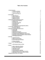
Table of the Contents
1. Product Overview
1.1 Features at a Glance
1.2 Library Configuration
1.3 Development Manuals
2. Prerequisites
2.1 Skills Required
2.2 Hardware Required
2.3 Systems Required
2.4 Software Required
3. Setting up the Development Environment
3.1 Application Development
3.2 Installing JDK
3.3 Installing Android SDK
3.4 Installing Eclipse
3.5 Installing ADT
3.6 Installing Software Development Kit (“SDK”)
4. Connecting V-T500/V-N500 to PC
4.1 Installing USB Driver
5. Setting Up the Development Environment
5.1 Setting JDK
5.2 Setting AVD
5.3 Setting Android Project
5.4 Setting Up the Debugging Environment
5.4.1 Setting the Debug Configuration with Terminal
5.4.2 Setting the Debug Configuration with the Emulator
5.4.3 Debugging Applications
6. Emulator
6.1 Software Required
6.2 Starting Up the Emulator
6.2.1 How to Start Up the Emulator
6.3 Using the Emulator
6.3.1 V- T500/V-N500 Emulator
7. Eclipse
7.1 Developing with System Library
8. Kitting
8.1 New Configuration of System
8.1.1 Flow of New Configuration
8.1.2 Design the system
8.1.3 Set Environment
8.1.4 Install Application Software
8.1.5 Replicate Environment to Other Terminals
8.1.6 Set Specific Environment of Each Terminal
9. Appendix Default Values of the Setting
2
4
4
6
6
7
7
7
7
8
9
9
10
13
17
19
24
25
25
28
28
29
31
33
33
34
35
38
38
38
38
41
41
42
42
61
61
61
61
61
62
63
66
68
No part of this reference manual may be produced or transmitted in any form or by any means, electronic or
mechanical, for any purpose, without the express written permission of CASIO Computer Co., Ltd. in Tokyo
Japan. Information in this reference manual is subject to change without advance notice. CASIO Computer Co.,
Ltd. makes no representations or warranties with respect to the contents or use of this manual and specifically
disclaims any express or implied warranties of merchantability or fitness for any particular purpose.
© 2012 CASIO Computer Co., Ltd. All rights reserved.
3
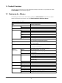
1. Product Overview
This guide clearly and concisely sets out the information developers need to know to get started with CASIO
V-T500/V-N500 series terminals development.
1.1 Features at a Glance
The following is a brief overview of the features available on V-T500/V-N500series terminals. For further
details on the hardware specifications, refer to V-T500/V-N500Series Hardware Manual.
Table 1.1 Features at a Glance
CPU
Memory
Platform
LCD
RAM
F-ROM
Model
Size
Pixel
Color
Viewing angle
Backlight
LED
Touch panel
Button
Bluetooth®
communication
Version
Communication range
NFC
Class
Model
SIM
SAM
Wireless LAN
Antenna
Standard
General specification
Standard
General specification
Standard specification
Communication system
Modulation method
V-T500/V-N500
OMAP 1.5 GHz Dual core
1 GB
16 GB
Android 4.0
IPS mode TFT color LCD
10.1 inch
1280 x 800 Wide XGA
16.7
80°
LED Backlight
Red x 1, Green x 1
(For confirmation of charging/state of operation)
Capacitive touch panel with Multi-Touch
Input :Pen-type digitizer
Power button/function buttons A and B/
Volume button (UP/DOWN)/
Screen locking button (display rotation locking button)
Bluetooth® Specification Ver.4.0+EDR
Approximately 5 meters(Varies depending on conditions of radio wave
and environment.)
2 (Output 2.5 mW Range 10 m)
ISO14443 Type A (Mifare)
ISO14443 Type B
Felica(JIS X 6319)
ISO15693 (Tag)
Magnetic loop antenna
ISO 7816 IC Card Standard
ISO 7816 IC Card Standard
IEEE 802.11a/b/g/n
Spread Spectrum Communication System
BPSK,QPSK,CCK,16QAM,64QAM
4
Transfer rate
Communication range
Output
GPS
General specifications
Positioning scheme
SD card slot
Micro SD card slot
USB
Camera
Effective pixels
Aperture
Focal length
Focus distance
LED light
Speaker
Microphone
Power source
Main Battery
Sub-battery
Temperature
Humidity
Drop strength
Waterproof and dustproof performance
Size
802.11a/g: up to 54Mbps
802.11b:up to 11Mbps
802.11n:up to 72Mbps
802.11b/g/n: 50m (in-door), 150 m
(out-door) (2.4GHz band for /n)
802.11a/n : 30m (in-door), 150 m
(out-door) (5GHz band for /n)
802.11a:12.0dBm min. Typical 13.5dBm
(at 54Mbps)
802.11b:17.0dBm mini. Typical 18dBm
(at 11Mbps)
802.11g:12.0dBm mini. Typical 14dBm
(at 54Mbps)
802.11n:11.0dBm min. Typical 12.5dBm
(at 72Mbps)
1575.42 MHz, C/A Code
Self-ephemeris
Supporting SDHC/SDIO cards
Supporting SDHC card
USB host x 1
USB devicex 1
Approx. 2M Pixels (2592×1944 pixels)
F2.8±5%
f=3.4mm±5%
10cm to infinity
21,000mcd()
Alarm, etc.
Voice input
Lithium Ion Polymer Rechargeable Battery
1 x Lithium Ion Secondary Battery
-20 to 50 °C
10 to 90% RH
1.0 m
IP54-compliant
269 mm x 190 mm x 14 mm
5
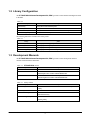
1.2 Library Configuration
The V-T500/V-N500 Software Development Kit (“BDK”) provides various libraries including those listed
in the table.
Table 1.2
Library
System Library
SAM Library
Authentication library
Camera scanning library
Description
Library that is used to control the system.
Library that is used to communicate with the SAM Card.
Library that is used to set the authentication function such as the password.
Library that is used to scan symbols with the camera.
The following table shows each file name of the jar files.
Table 1.3
Library
System Library
SAM Library
Authentication library
Camera scanning library
jar file
jp_casio_vx_framework_system.jar
jp_casio_vx_framework_sam.jar
jp_casio_vx_framework_authenticate.jar
jp_casio_vx_framework_camerascanner.jar
1.3 Development Manuals
The V-T500/V-N500 Software Development Kit (“BDK”) provides various development reference
manuals as described in the table below.
Table 1.4 V-T500/V-N500 manual
Development Manual
Description
Quick Start Guide
This reference manual.
Hardware Manual
Reference manual that describes hardware specifications in detail on each
dedicated option and V-T500/V-N500 handheld terminal.
Software Manual
Reference manual that describes software specifications in detail for all the
software integrated in V-T500/V-N500 handheld terminal.
Table 1.5 Library manual
Development Manual
System Library Manual
SAM Library Manual
Authentication Library Manual
Camera Scanning Library Manual
Description
Reference manual that describes individual functions in detail for System
Library.
Reference manual that describes individual functions in detail for SAM Library.
Reference manual that describes individual functions in detail for
Authentication Library.
Reference manual that describes individual functions in detail for Camera
Scanning Library.
6
2. Prerequisites
2.1 Skills Required
V-T500/V-N500 application can be developed by the following languages:
• Java
The following skills or experience are also desirable:
• Android OS
• Development of Android applications
• Eclipse integrated development environment
• Some networking experience
2.2 Hardware Required
The following models and dedicated options are available.
Table 2.1 List of available model
Model no.
Remark
V-N500
V-T500
2.3 Systems Required
PC Operating System
One of following OS (in case of 32 bit) is required.
• Microsoft Windows Vista Service Pack 2 or later
• Microsoft Windows 7 Service Pack 1 or later (Professional/Ultimate)
One of following OS (in case of 64 bit) is required.
• Microsoft Windows 7 Service Pack 1 or later (Professional/Ultimate)
Main unit of the computer
The personal computer on which the OS above operates
Memory
Secure the necessary and adequate capacity for operating the OS above.
The necessary capacity varies according to the OS used. In either case, a capacity of 1 GB or more is
recommended.
Hard disc capacity
10 GB or more free space is recommended.
7
2.4 Software Required
The Android development environment is required for developing the V-T500/V-N500 application.
Table 2.2 Development platform
Programming Language
Java
Detail
Java SE Development Kit (JDK compiler-compliant level 1.6)
Android SDK (API level 15)
Eclipse 3.7 (Indigo)
ADT Plugin for Eclipse
Table 2.3 The URL where each tool is supplied
JDK
Tool
Manual Version no.
6 (u31 or later)
Detail
http://www.oracle.com/technetwork/java/javase/downloads/index.html
Android SDK
r18 and r20
(old) http://dl.google.com/android/installer_xxx-windows.exe
(Case of r20) http://dl.google.com/android/installer_r20-windows.exe
(latest) http://developer.android.com/sdk/index.html
Eclipse
3.7 (Indigo)
http://www.eclipse.org/downloads/packages/release/indigo/sr2
ADT
15.0.0 or later
20.0.0 or earlier
(old) http://dl.google.com/android/ADT-xx.x.x.zip
(Case of 20.0.0) http://dl.google.com/android/ADT-20.0.0.zip
(latest) https://dl-ssl.google.com/android/eclips
Note: The URLs above are as of April 4, 2013.
8
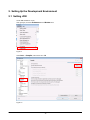
3. Setting up the Development Environment
3.1 Application Development
This chapter explains what to set up for the development environment before starting your application
development.
(1) Installing JDK/Android SDK/Eclipse/ADT
Install the development environment for the Android application on the PC.
For details, refer to Chapter 2.4 Software Required.
(2) Installing CASIO SDK to PC
Install CASIO SDK on the PC.
For the installation method, refer to Chapter 3.6 Installing Software Development Kit (“SDK”).
(3) Connecting V-T500/V-N500 to PC
Connect V-T500/V-N500 to PC.
For the connection method, refer to Chapter 4. Connecting V-T500/V-N500 to PC.
(4) Preparing the Device Emulator
Prepare to use the CASIO V-T500/V-N500 device emulator on the PC.
For the operation method, refer to Chapter 6. Emulator.
If no device emulator is required, proceed to (5).
(5) Application Development
Now, the application development environment is set up and your development with the development
platform can be started.
After an application has been developed, transfer it to the Device Emulator or an actual terminal of
V-T500/V-N500 via the tool of (3) to check the operability.
For the application development method and transferring your application, refer to Chapter 7. Eclipse.
9
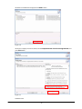
3.2 Installing JDK
Java SE JDK can be downloaded from the Java site. Access the Java site, and download the Java SE JDK
package compatible with the Windows platform used.
The URL and the details of the Java site may differ from those given in this document because the site has been
updated.
When downloading Java SE JDK, access the Java site from a search site, and follow the procedures explained
on the site.
http://www.oracle.com/technetwork/java/javase/downloads/index.html
Figure 3.1
jdk-6u31-windows-i586.exe (32 Bit version) is downloaded in the example below.
Download the 64 bit version for the 64 bit version OS.
10
Figure 3.2
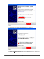
Start the downloaded file, and execute installation.
For installation, execute the downloaded file by a user who has administrative authority.
If you wish to execute it by a user who does not have administrative authority, right-click on the downloaded file
on the explorer, select Execute as the administrator from the displayed menu, and execute it.
No changes are required during installation.
Figure 3.3
11
Figure 3.4
Figure 3.5
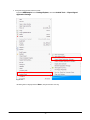
When the installation is finished, set the folder where JAVA is installed in the environment variable
JAVA_HOME, and log in again. Pay attention because if you forget this setting, an error occurs when installing
Android SDK.
12
Figure 3.6
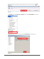
3.3 Installing Android SDK
Android SDK is available from the Android of Google site.
Please input the URL at browser, and download Android SDK and its installer.
http://dl.google.com/android/installer_xxx-windows.exe
At the “xxx” part of above URL, input the version of the object to download.
In case of Android SDK r20, it is “http://dl.google.com/android/installer_r20-windows.exe”.
When the download of Android SDK is finished, execute the downloaded file by a user who has administrative
authority.
If you wish to execute it by a user who does not have administrative authority, right-click on the downloaded file
on the explorer, select Execute as Administrator from the displayed menu, and execute it.
13
Figure 3.7
Figure 3.8
Close the installer as is.
Figure 3.9
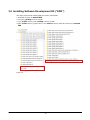
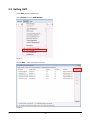
Execute SDK Manager from the menu of Android SDK Tools by a user who has administrative authority.
14
If you wish to execute it by a user who does not have administrative authority, right-click on SDK Manager in
the menu of Android SDK Tools, and select Execute as the administrator from the displayed menu, and
execute it.
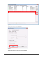
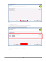
Select Reload from the Package menu.
Figure 3.10
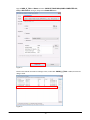
The list of packages is updated to the latest version.
Check Android SDK Platform-tools in Tools, and Android 4.0.3(API15) and Google USB driver in
Extras, then install.
Please do not check Android SDK Tools in Tools.
Please pay attention because Android 4.0.3 (API15) is not checked by default.
Figure 3.11
15
Figure 3.12
Add the paths related to Android SDK to PATH of the system environment variable.
Add paths to tools under the The folder Android SDK is installed, and platform-tools under the The
folder Android SDK is installed.
Figure 3.13
16
3.4 Installing Eclipse
Install the integrated development environment Eclipse. The flow of installation of Eclipse IDE for Java
Developers of Eclipse 3.7 Indigo is explained in this section.
Eclipse IDE for Java Developers can be downloaded from the Eclipse site. Access the Eclipse site, and
download the package of Eclipse IDE for Java Developers compatible with the Windows platform used.
The URL and the details of the Eclipse site may differ from those given in this document because the site has
been updated.
When downloading the Eclipse IDE for Java Developers, access the Eclipse site from a search site, etc.,
follow the procedures explained on the site.
http://www.eclipse.org/downloads/packages/release/indigo/sr2
Figure 3.14
17
Figure 3.15
Extract the downloaded file, extract the package of Eclipse IDE for Java Developers, and extract the route
directory of Eclipse, and all directories and files under the route directory in the configuration as is.
Execute Eclipse.exe under the route directory of Eclipse, and confirm that it can be started.
18
3.5 Installing ADT
When Eclipse is installed, install ADT next.
ADT incorporates various tools to simplify the development of Android applications on Eclipse.
Input the following URL at browser, then download an archive file of ADT.
http://dl.google.com/android/ADT-xx.x.x.zip
At the “xx.x.x” part of above URL, input the version of ADT to download.
In case of ADT 20.0.0, it is “http://dl.google.com/android/ADT-20.0.0.zip”.
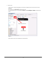
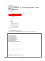
Start up Eclipse, and select Install New Software… of the Help menu.
Figure 3.16
Press the Add… button.
19
Figure 3.17
20
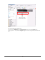
Input “ADT Plugin” at Name.
Press Archive button, then select a path of downloaded ADT file.
Press OK button if Name and Location is specified correctly.
Figure 3.18
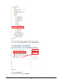
Select ADT Plugin at Work with.
A list of the packages that can be installed is displayed. Check Developer Tools and press Next > button.
Figure 3.19
21
The details of installation are displayed. Press Next > button.
Figure 3.20
The license is displayed. Check the details, select I accept the terms of the license agreements, and
press finish button.
Figure 3.21
Installation starts.
22
If a dialog is displayed in the middle of the operation that prompts to restart as shown below, press Restart
Now button..
Figure 3.22
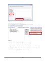
After Eclipse restarts, select Preferences of Window menu to set the Android SDK folder, which was
installed previously
Preferences dialog as shown below is displayed. Set the Android SDK folder in the same way.
Figure 3.23
23
3.6 Installing Software Development Kit (“SDK”)
This chapter explains about installing SDK and construct Android SDK.
1. Install SDK as add-on for Android SDK.
2. Navigate to “package” directory of SDK.
3. Copy “V-T500” directory under “package” directory of SDK.
4. Paste “V-T500” directory copied in above 3 into “add-ons” directory under the root directory of Android
SDK.
Figure 3.24
24
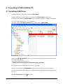
4. Connecting V-T500/V-N500 to PC
4.1 Installing USB Driver
Install the USB driver to connect the PC and the V-T500/V-N500.
Only the configuration file of the USB driver is included in the V-T500/V-N500 development kit.
The USB driver is included in the Android SDK, which was installed in Chapter 3.3 Installing Android SDK.
First, create a folder for the driver (e.g. “C:\V-T500Driver”).
Next, search a file named android_winsub.inf in the installed folder of Android SDK.
Figure 4.1
When the file android_winsub.inf is found, copy it along with the sub folders in the folder for the driver that
you created at the beginning.
Then, copy the following file from the CD.
V-T500/V-N500 development kit.\V-T500\driver\ android_winsub.inf
Paste the file in the same folder for the driver as above by overwriting.
When the mini-B USB port of V-T500/V-N500 and the USB port of the PC are connected by cable, the
connection is automatically detected by the OS, and the following dialog is displayed. Follow the instructions on
the screen.
Select No. not this time, and press Next. > button.
25
Figure 4.2
Select Install from a list or specific location [Advanced] and press Next > button.
Figure 4.3
Check Include this location in the search:, and specify the folder for the driver that you created previously.
26
Figure 4.4
Installation is started.
When the dialog below is displayed, installation is finished. Press Finish button, and close the dialog.
Figure 4.5
For confirmation, open the command prompt, and enter the following command: adb devices
Figure 4.6
If the message above is displayed, the installation of the driver has succeeded.
27
5. Setting Up the Development Environment
5.1 Setting JDK
Set the JDK installation version.
Start up Eclipse, and select Preferences of the Window menu.
Figure 5.1
Select Java → Compiler, and set the level to 1.6.
Figure 5.2
28
5.2 Setting AVD
Set the AVD (Android Virtual Device).
Start up Eclipse, and select AVD Manager.
Figure 5.3
Press the New… button, and create a new AVD.
Figure 5.4
29
Enter “CASIO_V_T500” in Name, and select “CASIO V-T500/V-N500(CASIO COMPUTER CO.,
LTD.) - API Level 15” at Target, and press the Create AVD button.
Figure 5.5
Return to the Android Virtual Device Manager screen, confirm that “CASIO_V_T500” is added, and close the
dialog to finish.
Figure 5.6
30
5.3 Setting Android Project
Set the Android Project of the application created by Eclipse.
Select and right-click Android Project, and select Properties.
Select Android in the displayed Properties dialog, and select CASIO V-T500/V-N500 at Target Name.
Figure 5.7
Next, select Java Build Path.
Press Add External JARs...button in the Libraries tab, and display the file selection dialog.
31
Figure 5.8
Open the libs folder under the SDK, and select all files.
Figure 5.9
Next, open the Order and Export tab, check all the added files, and press OK button to finish.
32
Figure 5.10
5.4 Setting Up the Debugging Environment
Set the debugging environment of the application.
Note: For the procedure to create the application, refer to Chapter 7. Eclipse.
Use the actual terminal of V-T500/V-N500 or the emulator for debugging.
5.4.1 Setting the Debug Configuration with Terminal
Select Debug Configurations… from the Run menu of Eclipse.
Figure 5.11
33
Select the Android tab, and enter the debugging project name in Project.
Figure 5.12
Switch to the Target tab, select Always prompt to pick device, and close the dialog with the Close button.
Figure 5.13
Set the USB drier as described in the Chapter 4. Connecting V-T500/V-N500 to PC before connecting the actual
terminal of V-T500/V-N500 and the PC.
5.4.2 Setting the Debug Configuration with the Emulator
Select Debug Configurations from the Run menu of Eclipse in the same way as the actual terminal of
V-T500/V-N500.
Enter the details of Android tab, the debugging project name, in the same way as the actual terminal of
V-T500/V-N500.
Figure 5.14
34
Next, select the Target tab.
Select Automatically pick compatible device:~, and check CASIO_V_T500 in the check box below.
Figure 5.15
Press Close button, and close the dialog.
5.4.3 Debugging Applications
Basic operation of debugging
The debugging method is the same as the normal debugging operation of Eclipse.
Select Debug from the Run menu of Eclipse, or press F11 to start debugging.
35
Figure 5.16
Debugging by the actual terminal (V-T500/V-N500)
Before debugging, connect the actual terminal to the PC with a USB cable.
Set the USB drier as described in the Chapter 4. Connecting V-T500/V-N500 to PC before connecting the actual
terminal and the PC.
When Debug is selected from the Run menu, the screen for selecting the device as shown below is displayed.
Figure 5.17
36
Select the target device, and press the OK button to start debugging.
It is possible to execute debugging by stepping, etc. on the actual terminal by setting breakpoints in the source
code.
Precautions for debugging
•
It is not possible to execute debugging when the debugging application is installed on the actual terminal of
V-T500/V-N500. In such a case, uninstall the debugging application on the actual terminal of
V-T500/V-N500 before executing debugging.
Debugging with the emulator
When Debug is selected, debugging starts on the emulator if an existing emulator is operating, and by starting
the emulator newly if no emulator is operating.
It is possible to execute debugging by stepping, etc. on the V-T500/V-N500 emulator by setting breakpoints in
the source code.
37
6. Emulator
The emulator provides an “environment where basic operation check of the application and
source level debugging are possible without the actual terminal of V-N500” to the application
developer.
6.1 Software Required
It is possible to use the emulator if you have built the development environment explained above.
6.2 Starting Up the Emulator
6.2.1 How to Start Up the Emulator
Start AVD Manager from the Windows menu of Eclipse.
Figure 6.1
Select CASIO_V_T500 and press the Start button.
38
Figure 6.2
The dialog below is displayed. Press Launch as is.
Figure 6.3
The dialog below is displayed, and the process of start up is displayed.
39
Figure 6.4
The emulator starts.
Figure 6.5
40
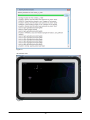
6.3 Using the Emulator
6.3.1 V- T500/V-N500 Emulator
Key input function
The key input function equivalent of the actual terminal (V-T500/V-N500) is incorporated.
It is possible to use key input by clicking the keys on the screen with a mouse.
Function to save the state
The V-T500/V-N500 emulator does not have a function to save the state when it finishes.
The clock and the file system of the emulator are initialized when it starts up.
41
7. Eclipse
The application development procedure using Eclipse as the development environment is explained in this
chapter.
The example is an application that beeps a large-sound buzzer once for a second using the system library.
Create this application in a Java programming language.
For the list of libraries provided with the V-T500/V-N500 basic development kit, refer to the
Chapter 1.2 Library Configuration.
For the details of the system library, refer to System Library Manual.
The example program of this chapter does not operate because the emulator does not have a large sound buzzer.
Check the operation on the actual terminal of V-T500/V-N500.
7.1 Developing with System Library
In this section, the GUI application that gets the model name of terminal in Java is explained.
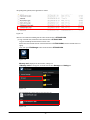
Tap and start up.
The confirmation dialog is displayed when it operates normally.
Figure 7.1
42
1. Create a new Android application on Eclipse.
Figure 7.2
The application name is the name of the application created. This name is displayed on the menu of Android. It is
named SDKSample1 in this example.
The project name is the name of the project created in the workspace of Eclipse.
Two or more projects of the same name cannot exist in the workspace. The project name is SDKSample1 in
this example.
The package name is the name to avoid collision of the class names of Java during execution. Since it is desirable
to have a unique name in the world, the domain name of the developer is normally used.
Note that the hierarchy of the package becomes lower in the order of left → right with Java, which is opposite the
domain description by URL.
It is named jp.casio.vx.framwork.sdksample1 in this example.
All the other settings are default in this example.
43
Figure 7.3
Next, set the launcher icon. Select the typical Android icon in this example.
Figure 7.4
Next, set the activity.
Activity is one of the Java classes in specific. It works as units of the user interface of the Android application,
44
and display, response to events, etc. are included.
The title is changed to V-T500 System Lib sample in this example. The title is displayed as the screen title
when executing an application or the menu title.
Figure 7.5
45
2. Set the Android project.
When a new project is created, follow the procedure described in Chapter 5.3 Product Overview first. If this
process is omitted, an error occurs in a subsequent process.
For the operations after this, refer to the Chapter 5.3 Setting Android Project
Figure 7.6
46
3. Create a screen.
When a project is created, the edit display as shown below is displayed at first. It becomes the screen of the
application.
First, delete the text “Hello world!” displayed at the center.
Next, drag & drop the grey icon which indicates Button from Form Widgets in Palette on the left into the
screen.
Drag & drop in the screen
Select and delete
Figure 7.7
Paste the button on the screen, and adjust the size and the position.
47
Adjust the size and the
position with the mouse.
Figure 7.8
Next, create a resource of the character strings.
Open the project of SDKSample1 from Package Explorer on the left side of the Eclipse screen.
When you point res → values, the file “strings.xml” appears as shown in the figure below, then double-click
on it.
48
Figure 7.9
The resource editing dialog as shown in the figure below is displayed.
First, select unnecessary hello_world, and press the Remove button.
Select and remove.
Figure 7.10
Next, press the Add button.
The dialog below is displayed. Select String.
49
Figure 7.11
Set the name and the value in the new string resource.
The name “button_title” and the value “Get model name!” are set in this example.
Figure 7.12
When editing is finished, select Save from the File menu, and save the change.
Change the details of the text displayed on the button in the Text in Properties at the lower right while
selecting the button.
Enter “@string/button_title” in this example. When it is entered, the display on the button changes to “Get
model name!”.
It indicates the text resource “button_title” that you have just created.
50
Figure 7.13
Next, enter “onClick” in On Click in Properties in the same way.
It is the name of the method in the activity that is executed when the button is pressed. (It is created later.)
Figure 7.14
51
4. Create a program.
Next, open the source of the activity.
Open in the order of SDKSample1 → src → jp.casio.vx.framework.sdksample1 from Package
Explorer, and
double-click MainActivity.java.
Figure 7.15
Correct MainActivity.java as shown below.
(For the specifications of the System library currently used, refer to the manual of the library.)
package jp.casio.vx.framework.sdksample1;
import android.os.Bundle;
import android.app.Activity;
import android.app.AlertDialog;
import android.view.Menu;
import android.content.Context;
import android.view.View;
import jp.casio.vx.framework.system.Api;
public class MainActivity extends Activity implements
View.OnClickListener
{
@Override
public void onCreate(Bundle savedInstanceState) {
super.onCreate(savedInstanceState);
setContentView(R.layout.activity_main);
}
@Override
public boolean onCreateOptionsMenu(Menu menu) {
getMenuInflater().inflate(R.menu.activity_main, menu);
52
return true;
}
public void onClick(View view)
{
jp.casio.vx.framework.system.Api sysapi
= new jp.casio.vx.framework.system.Api(this);
//Get model name of terminal
String modelName = sysapi.getModelNameString();
if(modelName.length() > 0) {
showDialog(this,"SDK Sample",
"The model name of this terminal is "+ modelName);
}else {
showDialog(this,"SDK Sample","Can't get model name.");
}
}
private static void showDialog(Context context, String title, String text)
{
AlertDialog.Builder ad=new AlertDialog.Builder(context);
ad.setTitle(title);
ad.setMessage(text);
ad.setPositiveButton(“OK”, null);
ad.show();
}
}
Save the source by Save All of the File menu after entering the source.
Figure 7.16
After saving the source, execute build. When any error occurs, correct as necessary.
53
Figure 7.17
After the build, debug as necessary. For the details of debugging, refer to Chapter 5.4 Product Overview.
And since the beep of the buzzer is the main function in this sample, it is recommended to debug on the actual
terminal of V-T500/V-N500.
54
5. Incorporate the application into the terminal.
Fight-click SDKSample1 on the Package Explorer, and select Android Tools → Export Signed
Application Package.
Figure 7.18
The dialog below is displayed. Press Next >, and proceed to the next step.
55
Figure 7.19
The dialog below is displayed.
This is setting of the certificate file to add a signature to Android applications.
The certificate file can be created here or select an existing one.
When you create a new one, set a password of at least 6 letters.
Figure 7.20
When you create a new key, the screen below is displayed.
Input all items.
56
Figure 7.21
Table 7.1
Item
Alias
Password
Confirm
Validity(years)
First and Last Name
Organization Unit
Organization
City of Locality
Description
Alias of the signature.
Password.
Enter the password for confirmation.
Specify the expiration in years. Specify 25 or more.
The name of the creator.
The name of the organization unit.
The name of the organization.
The name of the city.
Then, the dialog below is displayed.
Check the details of the Destination APK file, and finish with Finish button.
Figure 7.22
57
The package file (apk file) of the application is created.
Figure 7.23
There are two methods of installing this file on the actual terminal of V-T500/V-N500.
(1) Copy in the SD card, and install on the actual terminal of V-T500/V-N500.
Copy the created apk file from the PC to the SC card.
Set the SD card in the SD card slot of the actual terminal of V-T500/V-N500, and close the SD card cover
tightly.
Next, start up the File Manager on the actual terminal of V-T500/V-N500.
Figure 7.24
Memory card is displayed as shown below, and tap on it.
If Memory card does not appear, mount the SD card from Storage of the Setting tool.
Figure 7.25
The copied apk file is in the memory card. Tap on it, too.
Figure 7.26
58
The dialog below is displayed. Select Install button.
Figure 7.27
Installation of the application is finished.
Figure 7.28
After this, the application can be executed on the actual terminal of V-T500/V-N500.
Execute the application from the menu, and check the operation.
(2) Install from the PC side using the ADB command.
First, connect the terminal and the PC using a USB cable. (The mini B USB connector comes to the
terminal side.)
59
For details of connection, refer to Chapter 4. Product Overview.
Open the command prompt, and move the current folder to the location where the apk file exist.
The installation command is as shown below.
adb install -r SDKSample1.apk
The result of execution becomes as follows:
Figure 7.29
After this, the application can be executed on the terminal.
Execute the application from the menu, and check the operation.
60
8. Kitting
Installation of the application on the terminal, initial settings and update of the OS are described in this section.
8.1 New Configuration of System
The methods of making new settings and installing the application on the terminal are described.
8.1.1 Flow of New Configuration
(1) Design the System
(2) Set Environment
Configuration of the master unit
(3) Install Application Software
(4) Replicate Environment to Other Terminal
Configuration of the slave unit
(5) Set Specific Environment of Each Terminal
Configuration of the master unit/ the slave unit
Figure 8.1
8.1.2 Design the system
Depending on the usage of the terminal, design the system to be required and application software to install.
It’s recommended to design system with following points of view.
• Design for all terminals
• Design for each terminal
8.1.3 Set Environment
Make environment setting of the terminal.
There settings for the environment setting of the terminal are as follows:
1) Environment setting by the Settings tool
2) Setting the security for the administrator
3) Setting the security for general users
4) Setting the Job Menu
61
The settings above are all arbitrary settings.
Make setting as necessary.
1) Environment setting by the Settings tool
Basically, they can be used with the preset values.
For the setting of some items such as wireless setting, set according to the usage.
The preset values of the terminal are described in Appendix.
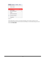
2) Setting the security for the administrator
Set the password for the administrator.
The password for the administrator is used for authentication for using a secure function.
It is also possible to set whether the user data should be deleted when authentication fails.
This setting is made using the Security Settings tool.
3) Setting the security for general users
Set the authentication information (user/password) for general users.
Multiple authentication information can be registered.
The authentication information is used for log-in authentication when using a terminal and administration of
Job Menu.
It is also possible to set whether the user data should be deleted when authentication fails.
This setting is made using the Account Edit tool.
4) Setting the Job Menu
This is the menu displayed instead of the Android standard home application.
It is possible to configure the menu configuration per user by associating with the general user mentioned
above.
Create the definition of the menu using the tool (menu editor) that operates on the PC (Windows).
8.1.4 Install Application Software
This section explains about the method to install the application on the terminal and configure the file used on the
application.
1) Registration method
The method of registering the application and the configuration file to the terminal is described below.
■ Registration using the flash memory
2) Registration using the flash memory
■ Facilities required
External storage medium: SD card or USB memory
■ Procedure
(1) Save the application (apk file) and the configuration file in the external storage medium.
(2) Set the external storage medium on the terminal.
(3) Start up the File Manager.
If the external storage medium set on the terminal does not appear on the File Manager, open the
Storage menu of the Settings tool, and mount the external storage medium.
62
(4) Install the application (apk file).
Tap the application (apk file) on the file manager, and install according to the displayed messages.
(5) Install the configuration file.
Press and hold the configuration file on the File Manager.
When it is held long, the Edit menu is displayed.
Select Copy from the Edit menu.
Move to the folder to install by the file manager.
When it is moved to the folder to install, select the Paste menu.
8.1.5 Replicate Environment to Other Terminals
The method of replicating the configured environment on another terminal (slave unit) after configuring a master
unit is described in this section.
Note that it is necessary to acquire a license for each copy of software when replicating the software.
1) Replication method
When replicating a configured environment of a terminal to another terminal can be conducted in the
following method.
It is possible to register in any method.
■ Replication of the environment using the Backup/Restore tool
■ Replication of the environment using the Copy Devices tool between master units
2) Details of replication
The details that can be replicated by the methods above are as listed below.
Details that can be replicated
(1) Environment setting set by the Setting tool
(2) Security setting for the administrator
(3) Security setting for general users
(4) Job menu setting
(5) The installed applications and configuration files (under the /data folder)
Note: It’s possible to replicate only by using Copy Devices tool .
3) Replication of the environment using Backup/Restore
■ Facilities required
External storage medium: SD card or micro SD card
■ Procedure
(1) Set an external storage medium on the master unit (replication source).
Open the Storage menu of the Settings tool, and confirm that the external storage medium is
mounted.
If the external storage medium is not mounted, mount it.
(2) Start up the Backup/Restore tool of the master unit (replication source)
The operation of the Backup/Restore tool on the master unit (replication source) is described below.
63
(3) Select the external storage medium to save the backup data in Option setting.
(4) Check All items in Backup.
(5) Tap Backup the selected items in Backup.
The backup data is stored in the “/Backup” folder in the external storage medium.
It is not necessary to create “/Backup” in the external storage medium in advance.
If there is already a “/Backup” folder in the external storage medium, confirm that there is no file under
the folder before executing this operation.
(6) When backup is completed, finish the Backup/Restore tool.
The description above is the operation of the Backup/Restore tool on the master unit (replication source).
(7) Remove the external storage medium from the master unit (replication source).
Open the Storage menu of the Settings tool, and implement unmount of the external storage
medium.
If the external storage medium is removed from the terminal without performing unmount, the external
storage medium may be damaged. Make sure to implement unmount.
Remove the external storage medium from the master unit (replication source).
(8) Initialize the slave unit (replication destination).
Delete the applications and setting files installed on the slave unit (replication destination), and return the
storage to the initial state.
Open the Backup & reset menu of the Settings tool, and execute Factory data reset..
(9) Set an external storage medium on the slave unit (replication destination).
Open the Storage menu of the Settings tool, and confirm that the external storage medium is
mounted.
If the external storage medium is not mounted, mount it.
(10) Start up the Backup/Restore tool of the slave unit (replication destination).
The operation of the Backup/Restore tool on the slave unit (replication destination) is described below.
(11) In Option setting menu of Backup/Restore tool , select the external storage medium where the
backup data is stored.
(12) Check Check All in Restore menu.
(13) Tap Restore selected items button in Restore menu.
(14) When restore is completed, finish the Backup/Restore tool.
The description above is the operation of the Backup/Restore tool on the slave unit (replication
destination).
(15) Remove the storage medium from the slave unit (replication destination)
Open the Storage menu of the Settings tool, and implement unmount of the external storage
medium.
64
If the external storage medium is removed from the terminal without performing unmount, the external
storage medium may be damaged. Make sure to implement unmount.
Remove the external storage medium from the slave unit (replication destination).
(16) Restart the slave unit (replication destination).
Press and hold the power supply button long, and shut down the slave unit (replication destination).
Press and hold the power supply button, and start up the slave unit (replication destination).
The replication of the environment on another terminal is completed.
4) Replication of the environment using the Copy Devices tool between master units
■ Facilities required
External storage medium: SD card or micro SD card
The external storage medium above is used for saving the backup data of the master unit (replication
source).
If the backup data is stored in the built-in memory internal storage) of the master unit (replication source),
the external storage medium is not necessary.
The built-in memory and the external storage medium are called “storage” in the following explanation.
If each of the built-in memory and the external storage medium should be mentioned clearly, it is described
as is.
The destination to transfer the backup data of the slave unit (replication destination) is the same storage as
the master unit (replication source).
If an SD card or a micro SD card is used as storage for the backup data, it is necessary to set (mounted) on
the terminal in advance on both the master unit (replication source) and the slave unit (replication
destination).
■ Procedure
(1) Start up the Backup/Restore tool of the master unit (replication source).
The operation of the Backup/Restore tool on the master unit (replication source) is described below.
(2) Select the storage to save the backup data in Option setting.
(3) Check All items in Backup.
(4) Tap Backup selected items in Backup menu.
The backup data is stored in the “/Backup” folder in the storage.
It is not necessary to create “/Backup” in the storage in advance.
If there is already a “/Backup” folder in the storage, the backup data is deleted.
(5) When backup is completed, finish the Backup/Restore tool.
The description above is the operation of the Backup/Restore tool on the master unit (replication source).
(6) Start up the Settings tool on the master unit (replication source), and enable WiFi-Direct in the
More… menu.
65
(7) Start up the Copy Devices tool on the master units (replication source).
(8) Select 2. Sender mode of the Copy Devices tool on the master units (replication source).
(9) Start up the Settings tool on the slave unit (replication destination), and enable WiFi-Direct in the
More… menu.
(10) Start up the Copy Devices tool on the slave unit (replication destination).
(11) Select 1. Receiver mode of the Copy Devices tool on the slave unit (replication destination).
Repeat Steps (9), (10) and (11) for all slave units (replication destinations).
(12) Select Start of the Copy Devices tool on the slave unit (replication destination).
In the first attempt, make sure to select Start of the Copy Devices tool on the slave unit (replication
destination) before selecting Start of the Copy Devices tool on the master unit (replication source).
When Start is selected and replication starts, the background color of the Copy Devices tool on
slave units (replication destination) becomes green.
(13) Select Start of the Copy Devices tool on the master unit (replication source).
When Start is selected and replication starts, the background color of the Copy Devices tool on the
master units (replication source) becomes blue.
Repeat Step (12) for all slave units (replication destinations).
It’s possible to add slave unit (replication destination) during replication.
(14) Execute restore of the backup data on the slave unit (replication destination), and restart it.
When it’s completed to transfer the backup data to the slave unit (replication destination), the
background color of the Copy Devices tool on the slave unit (replication destination) becomes
orange.
Then, the dialog to inform the completion of receipt and ask to execute restore and reset is appeared.
Select Yes in this dialog.
(15) Finish the Copy Devices tool on the master units of the master unit (replication source).
When replication of the environment on the prepared slave units (replication destinations) is completed,
select Finish in the Copy Devices tool on the master unit, and finish the Copy Devices tool on
the master unit.
The replication of the environment to other terminals is completed.
■ Precautions
If there is any other device that is the group owner of WiFi-Direct nearby, the slave unit (replication
destination) recognizes it as the master unit (replication source), and does not operate correctly.
When using the Copy Devices tool, confirm there is no such device nearby before use.
8.1.6 Set Specific Environment of Each Terminal
When configuration of the terminal common environment is finished, perform each terminal-specific
environment.
66
The environments that may be set separately on each terminal are as follows:
There are some environments that have to be set additionally according to the operation and the usage other than
the following:
■ Mail setting
■ WAN setting
■ WLAN (in case of fixed IP)
■ Security setting for the administrator
■ Security setting for general users
67
9. Appendix Default Values of the Setting
The initial values of the setting are described below.
■ WIRELESS & NETWORKS
The connection to the network and the devices using Wi-Fi, Bluetooth, mobile, network and USB connection
is set and managed.
It is also possible to set the connection between the tablet and a virtual private network (VPN), connect to the
Internet with another device via the data communication of the tablet, and turn off all wireless communication
by switching to in airplane mode.
Table 9.1
Default Value
Item
Wi-Fi
Bluetooth
Data usage
More…
Airplane mode
VPN
Tethering & portable hotspot
NFC
Android beam
Wi-Fi Direct
Wi-Fi Direct
(Set up peer-to-peer connectivity)
Mobile networks
OFF
OFF
ON
OFF
ON
OFF
OFF
-
■ DEVICE
It is possible to set the sound and the display, and check the state of the storage, the battery and the
applications.
The grayed-out items are used for confirmation of the state, and they are not the setting items.
Table 9.2
Sound
Display
Item
Volumes
Default notification
Vibrate and ring
Touch sounds
Screen lock sound
Vibrate on touch
Brightness
Wallpaper
Auto-rotate screen
Sleep
Font size
Default Values
Prescribed value
Pixie Dust
OFF
ON
ON
ON
Prescribed value
Prescribed value
ON
After 1 minutes of inactivity
Normal
Storage
Battery
Apps
68
■ PERSONAL
The settings related to usage of users and how to use such as various security settings are performed.
The grayed-out items are used for confirmation of the state, and they are not the setting items.
Table 9.3
Item
Accounts & sync
Locatioin services
Security
Language and input
Google's location service
GPS satelites
Screen lock
Owner info
Encrypt tablet
Set up SIM card lock
Make passwords visible
Device administrators
Unknown sources
Trusted credentials
Install from SD card
Clear credentials
Language
Spelling correctioin
Personal dictionary
Android keyboard
Backup and reset
Text-to-speech output
Pointer speed
Initialization of the data
69
Default Value
ON
OFF
ON
Slide
Lock SIM card
ON
OFF
Japanese (Japanese model)
English (Non Japanese model)
ON
Japanese IME (Japanese model)
Android keyboard (Non
Japanese model)
Pico TTS (ON)
Prescribed value
■ SYSTEM
The settings of date and time and the settings for developers are performed.
The grayed-out items are used for confirmation of the state, and they are not the setting items.
Table 9.4
Date & time
Accessibility
Developer
options
Item
Automatic date & time
Automatic time zone
Set date
Set time
Select time zone
Use 24-hour format
Select date format
Large text
Auto-rotate screen
Speak password
Touch & hold delay
Install web scripts
USB debugging
Development device ID
Stay awake
Allow mock locations
HDCP checking
Desktop backup password
Strict mode enabled
Pointer location
Show touches
Show screen updates
Show CPU usage
Force GPU rendering
Window animation scale
Transition animation
Don't keep activities
Background process limit
Show all ANRs
Default Value
ON
ON
Impossible to change
Impossible to change
Impossible to change
ON
Regional
OFF
ON
OFF
Short
Not allowed
ON
OFF
OFF
OFF
OFF
OFF
OFF
OFF
OFF
OFF
Animation scale 1x
Animation scale 1x
OFF
Standard limit
OFF
70