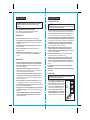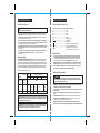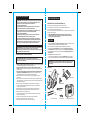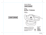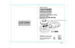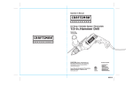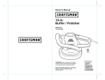
1
Operator’s Manual
®
P R O F E S S I O N A L
7 Amp
3 1/4-in. Planer
0
1/3
2
3/64
Model No.
172.267290
1/64
Double Insulated
CAUTION: Read, understand and follow
all Safety Rules and Operating Instructions
in this manual before using this product.
Sears Brands Management Corporation,
Hoffman Estates, IL 60179 U.S.A.
www.sears.com
3025736
• WARRANTY
• SAFETY
• UNPACKING
• DESCRIPTION
• OPERATION
• MAINTENANCE
7/6/12
SAFETY SYMBOLS
TABLE OF CONTENTS
Warranty……………………………...................................……………...Page
Safety Symbols……………………………...................................……... Page
Safety Instructions…………………………...................................……..Pages
Unpacking ………………………………..................................……........Page
Description............................................................................................Pages
Operation..............................................................................................Pages
Maintenance......................................................................................... Pages
Accessories...........................................................................................Page
Parts List...............................................................................................Pages
2
3
4- 9
9
10 -11
12 -17
18 -19
19
20 -21
CRAFTSMAN PROFESSIONAL ONE YEAR LIMITED WARRANTY
FOR ONE YEAR from the date of purchase, this product is warranted against any
defects in material or workmanship. With proof of purchase, a defective product will
be replaced free of charge.
For warranty coverage details to obtain free replacement, visit the web site:
www.craftsman.com
This warranty does not cover the blades, which are expendable parts that can
wear out from normal use within the warranty period.
This warranty gives you specific legal rights, and you may also have other rights
which vary from state to state.
Sears Brands Management Corporation, Hoffman Estates, IL 60179
SAVE THESE INSTRUCTIONS!
READ ALL INSTRUCTIONS!
The purpose of safety symbols is to attract your attention to possible dangers. The
safety symbols and the explanations with them deserve your careful attention and
understanding. The symbol warnings do not, by themselves, eliminate any danger.
The instructions and warnings they give are no substitutes for proper accident
prevention measures.
WARNING: Be sure to read and understand all safety instructions in this
manual, including all safety alert symbols such as “DANGER,” “WARNING,” and
“CAUTION” before using this planer. Failure to follow all instructions listed in
this manual may result in electric shock, fire and/or serious personal injury.
SYMBOL SIGNAL MEANING
SAFETY ALERT SYMBOL: Indicates DANGER, WARNING, OR CAUTION.
May be used in conjunction with other symbols or pictographs.
DANGER: Indicates a hazardous situation which, if not avoided, will result
in death or serious injury. This signal word is to be limited to the most extreme
situations. Always follow the safety precautions to reduce the risk of fire, electric
shock, and personal injury.
WARNING: Indicates a hazardous situation which, if not avoided, could result
in death or serious injury. Always follow the safety precautions to reduce the risk
of fire, electric shock, and personal injury.
CAUTION: Indicates a hazardous situation which, if not avoided, could
result in minor or moderate injury.
Damage Prevention and Information Messages
These inform the user of important information and/or instructions that could lead
to equipment or other property damage if they are not followed. Each message is
preceded by the word “NOTE,” as in the example below:
NOTE: Equipment and/or property damage may result if these instructions are not
followed.
WARNING: To ensure safety and reliability, all repairs
should be performed by a qualified service technician.
! WARNING: Some dust created by using power tools contains chemicals
known to the State of California to cause cancer and birth defects or other
reproductive harm.
2
WARNING: The operation of any power tools can result in
foreign objects being thrown into your eyes, which can result in
severe eye damage. Before beginning power tool operation,
always wear safety goggles or safety glasses with side shield
and a full face shield when needed. We recommend a Wide
Vision Safety Mask for use over eyeglasses or standard safety glasses with side
shields. Always use eye protection which is marked to comply with ANSI Z87.1
shields.
3
SAFETY INSTRUCTIONS cont.
SAFETY INSTRUCTIONS
!
WARNING: Read all safety warnings and instructions. Failure to follow
the warnings and instructions may result in electric shock, fire and/or
serious injury.
Save all warnings and instructions for future reference.
The term power tool in the warnings refers to your electric (corded)
power tool or battery-operated (cordless) power tool.
WORK AREA SAFETY
1. Keep work area clean and well lit. Cluttered or dark areas invite accidents.
2. Do not operate power tools in explosive atmospheres, such as in the presence of
flammable liquids, gases or dust. Power tools create sparks which may ignite the
dust or fumes.
3. Keep children and bystanders away while operating a power tool. Distractions can
cause you to lose control.
4. Make your workshop childproof with padlocks and master switches. Lock
tools away when not in use.
5. MAKE SURE the work area has ample lighting so you can see the work and that
there are no obstructions that will interfere with safe operation BEFORE using
your planer.
PERSONAL SAFETY
1. Stay alert, watch what you are doing and use common sense when operating a
power tool. Do not use a power tool while you are tired or under the influence of
drugs, alcohol or medication. A moment of inattention while operating power tools
may result in serious personal injury.
2. Use personal protective equipment. Always wear eye protection. Protective
equipment such as dust mask, non-skid safety shoes, hard hat, or hearing protection
used for appropriate conditions will reduce personal injuries.
3. Prevent unintentional starting. Ensure the switch is in the off-position before
connecting to power source and/or battery pack, picking up or carrying the tool.
Carrying power tools with your finger on the switch or energizing power tools that have
the switch on invites accidents.
4. Remove any adjusting key or wrench before turning the power tool on. A wrench
or a key left attached to a rotating part of the power tool may result in personal injury.
5. Do not overreach. Keep proper footing and balance at all times. This enables better
control of the power tool in unexpected situations.
6. Dress properly. Do not wear loose clothing or jewelry. Keep your hair, clothing and
gloves away from moving parts. Loose clothes, jewelry or long hair can be caught in
moving parts.
7. If devices are provided for the connection of dust extraction and collection
facilities, ensure these are connected and properly used. Use of dust collection
can reduce dust-related hazards.
4
TOOL USE AND CARE SAFETY
! WARNING: BE SURE to read and understand all instructions before
operating this planer. Failure to follow all instructions listed below may result in
electric shock, fire and /or serious personal injury.
1. Do not force the power tool. Use the correct power tool for your application. The
correct power tool will do the job better and safer at the rate for which it was designed.
2. Do not use the power tool if the switch does not turn it on and off. Any power tool
that cannot be controlled with the switch is dangerous and must be repaired.
3. Disconnect the plug from the power source and/or the battery pack from the power
tool before making any adjustments, changing accessories, or storing power tools.
Such preventive safety measures reduce the risk of starting the power tool accidentally.
4. Store idle power tools out of the reach of children and do not allow persons
unfamiliar with the power tool or these instructions to operate the power tool.
Power tools are dangerous in the hands of untrained users.
5. Maintain power tools. Check for misalignment or binding of moving parts,
breakage of parts and any other condition that may affect the power tools
operation. If damaged, have the power tool repaired before use. Many accidents are
caused by poorly maintained power tools.
6. Keep cutting tools sharp and clean. Properly maintained cutting tools with sharp
cutting edges are less likely to bind and are easier to control.
7. Use the power tool, accessories and tool bits etc., in accordance with these
instructions and in the manner intended for the particular type of power tool,
taking into account the working conditions and the work to be performed. Use of
the power tool for operations different from those intended could result in a hazardous
situation.
8. Use clamps or another practical way to secure and support the workpiece to a
stable platform.
9. Holding the work by hand or against your body leaves it unstable and may lead to
loss of control.
ELECTRICAL SAFETY
! WARNING: Do not permit fingers to touch the terminals of plug when
installing or removing the plug from the outlet.
1. Double insulated tools are equipped with a polarized
plug (one blade is wider than the other). This plug
will fit in a polarized outlet only one way. If the plug
does not fit fully in the outlet, reverse the plug. If it still
does not fit, contact a qualified electrician to install a
polarized outlet. Do not change the plug in any way.
2. Power tool plugs must match the outlet. Never
modify the plug in any way. Do not use any adapter
plugs with grounded power tools. Unmodified plugs
and matching outlets will reduce risk of electric shock.
5
Cover of
Grounded
Outlet Box
SAFETY INSTRUCTIONS cont.
SAFETY INSTRUCTIONS cont.
SAFETY SYMBOLS FOR YOUR TOOL
ELECTRICAL SAFETY cont.
!
WARNING: Double insulation DOES NOT take the place of normal safety
precautions when operating this tool.
3. Avoid body contact with grounded surfaces such as pipes, radiators, ranges and
refrigerators. There is an increased risk of electric shock if your body is grounded.
4. Do not expose power tools to rain or wet conditions. Water entering a power tool
will increase the risk of electric shock.
5. Do not abuse the cord. Never use the cord for carrying, pulling or unplugging the
power tool. Keep cord away from heat, oil, sharp edges or moving parts. Damaged
or entangled cords increase the risk of electric shock.
6. When operating a power tool outdoors, use an extension cord suitable for outdoor
use marked “W-A” or “W”. Use of a cord suitable for outdoor use reduces the risk of
electric shock.
7. If operating a power tool in a damp location is unavoidable, use a Ground Fault
Circuit Interupter (GFCI) protected supply. Use of a GFCI reduces the risk of
electric shock.
EXTENSION CORDS
USE PROPER EXTENSION CORD. Make sure your extension cord is in good
condition. When using an extension cord, be sure to use one heavy enough to
carry the current your product will draw. An undersized cord will cause a drop in
line voltage resulting in loss of power and overheating. Table 1 shows the correct
size to use depending on cord length and nameplate ampere rating. If in doubt,
use the next heavier gage. The smaller the gage number, the heavier the cord.
Table 1: Minimum Gage for Cord
Rating
120V
Ampere
More Than
0
6
10
12
Volts
Not More
Than
6
10
12
16
50
100
150
AWG
18
18
16
14
16
16
16
12
14
16
12
14
12
14
Not recommended
! CAUTION: Keep the extension cord clear of the working area. Position the
cord so that it will not get caught on lumber, tools or other obstructions while
you are working with a power tool.
! WARNING: Check extension cords before each use. If damaged replace
immediately. Never use tool with a damaged cord since touching the damaged
area could cause electrical shock, resulting in serious injury.
6
V.......................................................................Volts
A......................................................................Amps
Hz....................................................................Hertz
W..................................................................... Watts
min..................................................................Minutes
....................................................................Alternating current
.................................................................Direct current
no ....................................................................No-load speed
....................................................................Class II construction, Double Insulated
.../min..............................................................Revolutions or Strokes per minute
! .....................................................................Indicates danger, warning or caution.
It means attention! Your safety is involved.
SERVICE SAFETY
1. If any part of this planer is missing or should break, bend, or fail in any way;
or should any electrical component fail to perform properly: SHUT OFF the
power switch and remove the planer’s plug from the power source and have the
missing, damaged or failed parts replaced BEFORE resuming operation.
2. Have your power tool serviced by a qualified repair person using only identical
replacement parts. This will ensure that the safety of the power tool is maintained.
3. If the replacement of the supply cord is necessary, this has to be done by the
manufacturer or his agent in order to avoid a safety hazard.
SAFETY RULES FOR PLANERS
Total cord length (in feet)
25
The label on your tool may include the following symbols.
!
DANGER Keep hands away from cutting area and blade. Keep both
hands on the planer (rear handle and front handle). If both hands are holding
the planer, the blade cannot cut them.
1. ALWAYS use both hands when using the planer. Hold the front handle with your
left hand and the rear handle with your right hand.
2. Operate the planer with the chip chute exhaust turned so it points away from your
face and eyes.
3. To insure control, ALWAYS support your workpiece so the cut will be on your
right.
4. ALWAYS clamp the workpiece securely so it will not move when making the cut.
5. DO NOT use dull or damaged blades. Bent blades can break easily, or cause
kickback resulting in loss of control and serious injury.
6. ALWAYS hold the planer so the blades DO NOT come in contact with the
workpiece until you have squeezed the trigger switch and the planer has started.
7
SAFETY INSTRUCTIONS cont.
known to the State of California to cause cancer and birth defects or other
reproductive harm. Some examples of these chemicals are:
• Lead from lead-based paints.
• Crystalline silica from bricks and cement and other masonry products.
• Arsenic and chromium, from chemically treated lumber.
Your risk from these exposures varies, depending upon how often you do
this type of work. To reduce your exposure to these chemicals:
• Work in a well-ventilated area.
• Work with approved safety equipment, such as those dust masks that
are specially designed to filter out microscopic particles.
Avoid prolonged contact with dust from power sanding, sawing, grinding,
drilling and other construction activities. Wear protective clothing and wash
exposed areas with soap and water. Allowing dust to get into your mouth,
eyes, or lay on the skin may promote absorption of harmful chemicals.
! WARNING: Use of this tool can generate and/or disburse dust, which may
cause serious and permanent respiratory or other injury. Always use
NIOSH/OSHA approved respiratory protection appropriate for the dust exposure.
Direct particles away from face and body.
ADDITIONAL RULES FOR SAFE OPERATION
! WARNING: BE SURE to read and understand all instructions.
Failure to follow all instructions listed below may result in electric shock, fire
and/or serious personal injury.
1. Wait for the cutter to stop before setting the tool down. An exposed cutter may engage
the surface leading to possible loss of control and serious injury.
2. Use clamps or another practical way to secure and the workpiece to a stable
platform. Holding the work by hand or against your body leaves it unstable and may lead
to loss of control.
3. Hold tool by insulated gripping surfaces when performing an operation where the
cutting tool may contact hidden wiring. Contact with a ‘live’ wire with also make
exposed metal parts of the tool ‘live’ and shock the operator condition.
4. Remove the plug from the socket before carrying out any adjustment, servicing or
maintenance.
5. When an extension cable is required you must ensure it has the correct ampere rating for
your power tool and is in a safe electrical condition. Fully unwind cable drum extensions to
avoid potential overheating.
6. Ensure your mains supply voltage is the same as indicated on the rating plate.
7. Your tool is double insulated for additional protection against a possible electrical
insulation failure within the tool.
8. Always check walls, floors and ceilings to avoid hidden power cables and pipes.
9. After long working period’s external metal parts and accessories could be hot.
10. Wear eye protection when operating this tool.
11. The base plate must always be held firmly against the material being cut to reduce
vibration and blade jumping.
12. If possible, ensure the workpiece is firmly clamped to prevent movement.
13. Your Planer is a hand held tool; do not clamp your planer.
14. Before cutting, check the cutting line is free of nails, screws, etc.
8
SAFETY INSTRUCTIONS cont.
ADDITIONAL RULES FOR SAFE OPERATION cont.
15. Never stop the cutting blade by applying pressure to the blade.
16. Only withdraw the planer from the cut when the blade has stopped moving.
17. Only use blades in excellent cutting condition.
18. Do not put your fingers into the dust extraction. Use a wooden stick to unblock any material.
19. Always wear a dust mask.
20. SAVE THESE INSTRUCTIONS. Refer to them frequently and use them to
instruct others who may use this tool. If someone borrows this tool, make
sure they have these instructions also.
UNPACKING
1. Remove the Planer from the Storage / Carrying Case and inspect it carefully to make
sure that no breakage or damage has occurred during shipping.
2. Do not discard any of the packing materials until all parts are accounted for.
3. The planer has a Crescent Wrench force-fitted into the Storage / Carrying Case.
4. The Edge Guide is force-fitted into the top of the lid of the Storage / Carrying Case.
5. Also included with your planer and force fitted into the Storage / Carrying Case is a
Rabbet Guide.
6. Two blades are included with your planer.
7. If any of the parts are damaged or missing (refer to PARTS LIST below), return the
planer to your nearest Sears store or Craftsman outlet to have the planer replaced.
! WARNING: If any parts are missing, DO NOT operate this planer until the
missing parts are replaced. Failure to do so could result in possible serious
personal injury.
PARTS LIST
1. Planer
mm
0
Inches
0
2. Edge Guide
10
112
20
1
3/64
WARNING: Some dust created by using power tools contains chemicals
0
3. Rabbet Guide
1/3
2
!
1/64
5. Two
Blades
9
8. Operator’s Manual
4. Wrench
6. Two Screws
7. Storage / Carrying Case
DESCRIPTION cont.
DESCRIPTION
KNOW YOUR PLANER
This Professional Planer has the following features:
Fig. 1
Left or Right
Dust/ Chip
Extraction
Your planer has a precision-built electric motor and it should be connected to a 120-volt,
60-Hz AC ONLY power supply (normal household current). DO NOT operate on direct
current (DC). The large voltage drop will cause a loss of power and the motor will overheat.
If the planer does not operate when plugged into correct 120-volt, 60-Hz AC ONLY outlet,
check the power supply. This planer has a 10-ft., 2-wire power cord (no adapter needed).
10
Lock Off
Button
Front
Handle
3/64
This Professional Planer has the following features:
1. Powerful, heavy-duty 7-Amp motor provides high speed needed for fast, clean cuts
in most any type of wood. Precision balanced for smooth, quiet operation.
2. Low profile depth-of-cut control knob allows easy depth-of-cut adjustments from
0 to 1/8-in.
3. Grooved front shoe design for 45° bevel or chamfer cuts.
4. Ergonomically designed contoured top-mount handle and front assist handle
with soft grips for positive gripping, balance, control and comfort.
5. Heavy-duty extended length trigger switch conveniently located for comfort and
control. Lock-off button helps prevent accidental starts.
6. 3 1/4-inch cutting width for fast planing. Planes wide side of 2 x 4 board in one pass.
7. Uses reversible, double-edged hardened steel carbide-tipped blades that can be
used on both sides for longer blade life.
8. Includes edge guide for accurate, precise cuts on long or uneven workpieces.
9. Includes rabbet guide for making 11/16-in. deep rabbet cuts.
10. Chip chute keeps work surface clean and directs wood chips away from operator.
11. Permanently lubricated bearings for smooth, efficient operation and long life.
12. Cogged timing belt drive provides positive, precise power transmission.
13. High-impact plastic motor housing and handles help protect tool from damage and
reduce weight.
14. Includes high-impact resistant storage / carrying case.
Rear Handle
Trigger Switch
0
1/3
2
NOTE: Before attempting to use your planer, familiarize yourself with all of the
operating features and safety requirements.
1/64
Base plate stand
Depth Adjustment
Knob
PRODUCT SPECIFICATIONS
7 Amps
Input
Cutting Width
3 1/4 in.
Cutting Depth
0 to 1/8-in.
Max. Rabbet Cut
11/16-in.
Rating
120 volts, 60 Hz AC
No-Load Speed
12,000 RPM
11
OPERATION cont.
PREPARING FOR OPERATION
Your planer has a rear handle and front assist handle for ease of operation. They provide
the two-hand operation which is necessary to maintain proper control of the planer.
ALWAYS keep both hands clear of the blades and the cutting area.
ALWAYS use both hands when using the planer. Hold the front handle with your left hand
and the rear handle with your right hand (as shown in Fig, 2). This position makes your
planer easier to handle and keeps you clear of the chip exhaust.
! CAUTION: DO NOT plane too fast because this causes build up in the chip
exhaust. Chip build-up restricts air flow and can cause the motor to over heat.
Keep the cord away from the cutting area. ALWAYS place the cord so it does not hang up
on the work when you are making a cut.
! DANGER: If the cord hangs up on the work during the cut, release the trigger
switch immediately. Unplug the planer and check the cord for damage. If there is no
damage, reposition the cord to prevent it from hanging up again. If the cord has been
damaged, have it replaced before using your planer.
! WARNING: Using your planer with a damaged cord could cause electrical
shock resulting in serious injury.
12
Fig. 2
0
1/64
! WARNING: Keep a firm grip on the
tool with both hands at all times. Failure to do so
could result in loss of control leading to possible
serious injury.
TO ADJUST PLANING DEPTH (See Fig. 3)
The planing depth on your planer can be adjusted from 0 to 1/8 inch by rotating the depth
adjustment knob located on the front of your planer.
1. Unplug your planer.
! WARNING: Failure to unplug your planer could result in accidental starting,
causing serious injury.
2. To increase cutting depth, rotate knob in a
clockwise direction.
3. To decrease cutting depth, rotate knob in a
counterclockwise direction.
4. We recommend that you make test cuts in scrap
wood after each adjustment to make sure the
planer is removing the desired amount of wood.
NOTE: To protect the blades during storage,
transporting and when not in use, ALWAYS set
the blade depth adjustment to 0.
13
Fig. 3
nch
i
7/64
THE CORRECT WAY TO USE YOUR PLANER (See Fig. 2)
ALWAYS hold your planer as shown in Figure 2.
1. ALWAYS keep control of your planer. It makes cutting easier and safer, as shown in
Figure 2.
2. To help keep control, ALWAYS support your work so the cut will be on your right.
3. ALWAYS clamp your work so it does not move during the cut (see Figure 2).
The workpiece moving during a cut could result in the loss of control of the planer,
possibly causing serious injury.
The work moving during a cut could result in the loss of control of the planer, possibly
causing serious injury.
THE CORRECT WAY TO USE YOUR PLANER
(See Fig. 2) cont.
4. ALWAYS operate the planer with the chip chute
exhaust turned so it points away from your face
and eyes.
All visitors should wear safety glasses and be kept
a safe distance from the work area.
5. ALWAYS hold your planer so the blades DO NOT
come in contact with the work piece BEFORE
you squeeze the trigger switch and start the
planer.
3/64
! WARNING: Your planer should NEVER be connected to power supply when you
are assembling parts, making adjustments, changing belts or blades, cleaning planer,
or when not in use. Disconnecting planer will prevent accidental starting that could cause
serious injury.
1/32
OPERATION
0
1/64
Depth
Adjustment
Knob
To Increase
Cutting Depth
Turn Clockwise
To Decrease
Cutting Depth Turn
Counterlockwise
OPERATION cont.
OPERATION cont.
4
1/6
1/32
Fig. 5
! WARNING: Failure to unplug your
planer could result in accidental starting,
causing serious injury.
2. Insert the screw provided through the hole in
the edge guide.
3. Tighten screw securely into screw hole on
either side of the main shoe (see Fig. 5).
h
1/64
0
Screw
Edge
USING THE EDGE GUIDE
Guide
The Edge Guide easily attaches to either side of
the planer. It is ideal for planing long and uneven boards.
1. When making cuts with the Edge Guide ALWAYS hold it firmly against the edge of the
board you are planing.
ATTACHING THE RABBET GUIDE (See Fig. 6)
1. Unplug your planer.
! WARNING: Failure to unplug your planer could result in accidental starting,
causing serious injury.
2. Insert the screw provided through the flat washer, then through the slot in the rabbeting
plate.
3. Insert screw into screw hole on the right side
Fig. 6
of the main shoe and tighten securely
(see Fig. 6).
USING THE RABBET GUIDE
The Rabbet Guide attaches to the right side of
the planer. It is ideal for making rabbeting cuts
up to 11/16 inches thick.
1. When making a rabbet cut, ALWAYS place
the notch on the inside of the main shoe firmly
against the side of the board (see Fig. 6).
2. ALWAYS press the Rabbet Guide firmly
against the top surface of the board.
15
inch
7/64
14
3/64
ATTACHING THE EDGE GUIDE (See Figure 5)
1. Unplug your planer.
inc
0
EDGE PLANING / CHAMFERING (See Figure 4)
Your planer is designed with a groove in the front shoe. This groove is for chamfering the
edges of boards (see Fig. 4).
NOTE: ALWAYS make a practice cut on scrap wood to determine how much wood needs
to be removed from the board BEFORE making your actual cut.
1. Firmly hold the rear handle of the planer with
your right hand and the front handle with your
Fig. 4
left hand.
2. Place the groove of the planer on to the surface
to be cut.
3. Turn on planer and let it reach full speed.
4. Slowly move planer onto work.
5. ALWAYS maintain downward pressure on the
planer to keep it flat at the beginning and the
end of the work piece.
NOTE: Making several passes of more shallow
cuts will provide a smoother cut and makes it
easier to control planer.
ACCESSORIES INCLUDED WITH YOUR PLANER
To make your planer even more versatile we have included 2 special accessories.
They are an Edge Guide and a Rabbeting Plate.
7/64
GENERAL CUTTING
1. Adjust planer to desired depth.
2. ALWAYS grip the planer with your left-hand holding the front handle and your right
hand holding the rear handle.
3. Place front shoe flat on the work piece. ALWAYS make sure that the blades are not
touching the work piece.
4. Apply pressure to the front handle until the front shoe is flat on the work piece.
5. Push the On/Off button and Squeeze the trigger switch to start the planer and allow the
motor to reach maximum speed.
6. Hold the planer firmly and push it steadily in a forward direction onto the work piece.
NOTE: If you desire a smooth cut, push the planer slowly in a forward direction.
7. As you reach the end of your desired cut, ALWAYS apply downward pressure toward
the rear handle. This will help keep the rear section of the base in contact with the work
piece and help prevent the front of the planer from dipping and gouging your cut.
8. ALWAYS be careful to avoid hitting nails during the planing operation because this
could nick, crack or otherwise damage the blades.
NOTE: The blades in your planer are reversible, so they can be rotated until both
sides are dull.
NOTE: We suggest that you keep an extra set of blades on hand, so you can replace the
blades in your planer when they show signs of becoming dull. Always reverse or replace
blades in pairs.
Screw
Rabbet
Guide
0
1/64
Main
Shoe
Notch
OPERATION cont.
OPERATION cont.
TO ADJUST THE DEPTH OF RABBET CUT
1. Unplug your planer.
REPLACING THE BLADES (See Figures 7 to 9) cont.
Fig. 8
Bolts
! Warning: ALWAYS remove the piece of wood before starting your planer.
Failure to do so could result in the piece of wood being thrown from your planer, causing
possible serious injury.
USING THE LEFT OR RIGHT DUST / CHIP
EXTRACTION (See Figure 10)
The dust / chip chute can be adjusted for left or right
extraction. Turn chute clockwise for extraction on the
left side, or turn it counterclockwise for extraction on
the right side. The arrow on the top of the chute
indicates the direction the chips will be extracted.
Fig. 10
iona
Planer
Blade
em
Fig. 7
Wrench
syst
2. Place the planer upside down on the work bench. (See Fig. 7).
3. Use the wrench (included) to loosen the 3 bolts that hold the blade to the blade clamp.
To loosen bolts, turn them approximately 1/2 turn in a clockwise direction. (See Fig. 7).
4. Hold the blade clamp in position and use a piece of wood to slide the blade out of blade
clamp. (See Fig. 8).
5. Push down on blade guard when removing the blade from the blade clamp. (See Fig. 8).
Clamp
ion
! WARNING: Failure to unplug your planer could result in accidental starting,
causing serious injury.
6. Place new blade or reverse existing blade into
blade clamp. (See Fig. 9).
7. Check to be sure blade is properly positioned in
blade clamp and the blade edge is level with the
base. (See Fig. 9).
8. Securely re-tighten the 3 bolts.
9. Repeat the steps 3 through 8 above to change
or reverse the other blade.
10. Remove piece of wood from planer.
tract
REPLACING THE BLADES (See Figures 7 to 9)
The blades in this planer are reversible, so when the blades become dull, they can be
reversed.
ALWAYS REPLACE OR REVERSE THE BLADES IN PAIRS.
DO NOT ATTEMPT TO SHARPEN THE BLADES.
NEVER OPERATE YOUR PLANER WITH ONLY ONE BLADE INSTALLED.
1. Unplug your planer.
NOTE: DO NOT remove the blade clamp. This could alter the factory setting for cutting
height and blade height.
Blade
Fig. 9
NOTE: DO NOT adjust the height adjusting screws.
st ex
2. Place planer on a flat board or work piece.
3. Loosen the screw and position the bottom surface of the Rabbet Guide above the
board the same distance as the desired depth of cut.
4. Tighten screw securely.
! CAUTION: Blades are very sharp. ALWAYS handle blades very carefully.
Failure to do so could result in possible serious injury.
l du
! WARNING: Failure to unplug your planer could result in accidental starting,
causing serious injury.
bi-d
irect
Blade
Clamp
Piece
of
Wood
Wrench
Blade
Clamp
Bolts
Work
Bench
Blade
Blade Guard
16
17
MAINTENANCE cont.
MAINTENANCE
!
WARNING: To ensure safety and reliability, repairs, maintenance and
adjustments MUST be performed by a qualified service technician at a
Sears Service Center.
! WARNING: For your safety, ALWAYS turn off switch and unplug planer
from the power source before performing any maintenance or cleaning.
It has been found that electric tools are subject to accelerated wear and possible
premature failure when they are used to work on fiber glass boats and sports cars,
wallboard, spackling compounds or plaster. The chips and grindings from these materials
are highly abrasive to electrical tool parts, such as bearings, brushes, commutators, etc.
Consequently, it is not recommended that this tool be used for extended work on any
fiberglass material, wallboard, spackling compound or plaster. During any use on these
materials, it is extremely important that the tool is cleaned frequently by blowing with
an air jet.
ROUTINE MAINTENANCE cont.
LUBRICATION
Your Craftsman® Planer has been properly lubricated and is ready to use.
No further lubrication is needed under normal operating conditions. All bearings in the
planer are lubricated for the life of the tool.
ACCESSORIES
BLADES
The blades for your planer are currently available at your local Sears Store.
! WARNING: The use of attachments or accessories that are not
recommended may be dangerous.
! WARNING: Always wear safety goggles or safety glasses with side shields
during power tool operations, or when blowing dust. If operation is dusty, also
wear a dust mask.
ROUTINE MAINTENANCE
! WARNING: DO NOT at any time let brake fluids, gasoline, petroleumbased products, penetrating oils, etc. come in contact with plastic parts.
Chemicals can damage, weaken or destroy plastic, which may result in
serious personal injury.
Periodic maintenance allows for long life and trouble-free operation. A cleaning,
lubrication and maintenance schedule should be maintained. As a common
preventative maintenance practice, follow these recommended steps:
! WARNING: For your safety, ALWAYS turn off switch and unplug planer
from the power source before performing any maintenance or cleaning.
1. When work has been completed, clean the tool to allow smooth functioning of the tool
over time.
2. Use clean damp cloths to wipe the tool.
3. Check the state of all electrical cables.
4. Keep the motor air openings free from oil, grease and sawdust or woodchips,
and store tool in a dry place.
5. Be certain that all moving parts are well lubricated, particularly after lengthy exposure
to damp and /or dirty conditions.
18
19
20
S
R
E
X
M
Q
U
L
U
POWER PLANER – MODEL NUMBER 172.26729
X
Q
N
N
L
1
2
3
4
5
6
7
8
9
10
11
12
13
14
15
16
17
18
19
20
21
22
23
24
25
26
27
28
29
30
31
32
33
34
35
No.
SB19.0.02-00
SW55.58.0-00
SB19.0.15-00
SB19.0.05-00
ST05.07.21-00
SW56.12.0-00
SB19.0.21-00
SB19.0.07-00
SB19.0.22-00
SB19.2.01-00
SB19.0.30-00
SB19.0.29-00
SB19.0.13-00
SB19.0.01-00
SB19.0.12-00
STB50.15.00-00
ST01.02.04-00
SW50.11.3-00
STB51.15.00-00
ST03.17.00-00
ST02.18.10-00
SB19.0.06-00
SB19.3.01-00
SB19.0.26-00
SB19.0.19-00
SW59.44.0-00
SW55.57.0-00
SW60.75.0-00
SW55.11.0-00
SW50.12.0-00
SB19.0.20-00
SW59.47.0-00
SB19.0.04-00
SB19.0.16-00
SB19.1.06-00
Part No.
21
1
22
1
1
4
1
1
1
1
1
1
1
1
1
1
1
1
2
1
2
2
1
1
1
1
1
5
4
4
1
1
1
1
1
6
Quantity
36
37
38
39
40
41
42
43
44
45
46
47
48
49
50
51
52
53
54
55
56
57
58
59
60
61
62
63
64
65
66
67
75
76
77
No.
Part No.
SW57.24.0-00
SB19.1.04-00
SB19.1.08-00
SB19.1.05-00
SB19.1.03-00
SW58.15.0-00
SB19.F.02-00
SB19.F.04-00
SB19.1.01-00
SW59.07.0-00
SW60.82.0-00
SB19.F.01-00
SB19.0.14-00
SB19.0.18-00
SB19.0.17-00
SB19.0.25-00
SW59.61.0-00
SB19.F.03-00
SB19.0.03-00
SB19.0.23-00
SB19.0.24-00
SB19.0.11-00
SB19.0.28-00
SB19.0.09-00
SB19.0.08-00
SB19.0.10-00
SB19.4.00-00
SW21.32.21-00
ST08.01.03-00
SW55.56.0-00
ST05.01.01-00
SW02.32.03-00
ST25.33.02.2-00
ST25.23.02.0-00
ST25.23.02.2-00
SEE BACK PAGE FOR PARTS ORDERING INSTRUCTIONS
Handle
Self-tapping screw
Rated lable
Right cover
Rubber ring
Screw
Ring
Safety cover
Spring
Bearing holder
Ring
Protection plate
Fixing ring
Housing
Chip ejector
Stator
Ring
Bearing
Rotor
Carbon brush
Brush holder
Wind shield
Middle cover
Belt
Belt wheel
Nut
Self-tapping screw
Washer
Self-tapping screw
Bearing
Belt wheel
Nut
Left cover
Brand
Screw
Description
Screw
Upper blade nip
Blade
Lower blade nip
Washer
Bolt
Plate
Knob screw
Blade drive shaft
Nut
Washer
Parallel guide
Stand
Back base
Front base
Spring
Nut
Depth gauge
Front cover
Calibration divider
Spring
Calibration plate
Rubber ring
Knob stand
Nut
Knob
Dust collector
Cable and plug
Cable clamp
Self-tapping screw
Cable protector
Switch
Inter wire
Inter wire
Inter wire
Description
4
2
2
2
1
1
1
2
1
1
1
1
1
1
1
1
2
1
1
1
1
1
1
1
1
1
1
1
1
2
1
1
2
1
1
Quantity
The Model Number will be found on the Nameplate. Always mention the Model Number in all correspondence regarding your tool.
P
C
P
R
S
C E
POWER PLANER – MODEL NUMBER 172.267290
PARTS LIST
PARTS LIST cont.