1
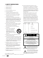
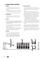
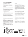
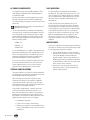
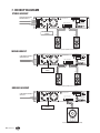
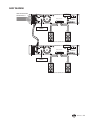
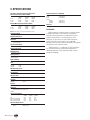
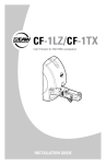
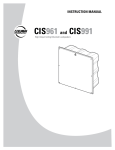
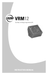
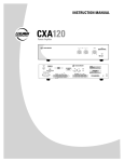
INSTRUCTION MANUAL
CAZ2500
CAZ1400
CAZ800
Power Amplifiers
OL
SIG
OL
SIG
ON
POWER
OFF
-
OO
dB
A
PUSH
B (+)
B (--)
INPUT
B
OFF
LINE
INPUT
CONNECTION
CAZ2500-AMPLIFIER
30
-
OO
dB
30
B
CAUTION
TO REDUCE THE RISK OF FIRE OR ELECTRIC SHOCK,
DO NOT EXPOSE THIS APPARATUS TO RAIN OR
MOISTURE. SEE INSTRUCTIONS BEFORE USING.
BREAKER
SERIAL /DATE CODE
ON
SUBSONIC
FILTER AT 30Hz
(BALANCED)
GND
AMP MODE
PUSH
A (--)
INPUT
A
MONO
STEREO
BRIDGE
A (+)
OFF
ON
CLIP LIMIT
LINE
(BALANCED)
CHANNEL B BRIDGED CHANNEL A
B (+) B (-) (+)
(-) A (+) A (-)
MANUFACTURED IN CHINA
2004 LOUD TECHNOLOGIES INC.
"EAW" IS A REGISTERED TRADEMARK
OF LOUD TECHNOLOGIES INC.
1. SAFETY INSTRUCTIONS
1.
2.
3.
4.
5.
6.
7.
8.
9.
10.
11.
12.
13.
14.
15.
16.
17.
18.
Read these instructions.
Keep these instructions.
Heed all warnings.
Follow all instructions.
Do not use this apparatus near water.
Clean only with dry cloth.
Do not block any ventilation openings. Install in
accordance with the manufacturer’s instructions.
Do not install near any heat sources such as radiators,
heat registers, stoves, or other apparatus (including
amplifiers) that produce heat.
Do not defeat the safety purpose of the polarized or
grounding-type plug. A polarized plug has two blades with
one wider than the other. A grounding-type plug has two
blades and a third grounding prong. The wide blade or the
third prong are provided for your safety. If the provided
plug does not fit into your outlet, consult an electrician for
replacement of the obsolete outlet.
Protect the power cord from being walked on or pinched
particularly at plugs, convenience receptacles, and the
point where they exit from the apparatus.
Only use attachments/accessories specified by the
manufacturer.
Use only with a cart, stand, tripod,
bracket, or table specified by the
manufacturer, or sold with the
apparatus. When a cart is used, use
caution when moving the cart/
apparatus combination to avoid injury
from tip-over.
Unplug this apparatus during lightning storms or when
unused for long periods of time.
Refer all servicing to qualified service personnel. Servicing
is required when the apparatus has been damaged in any
way, such as power-supply cord or plug is damaged, liquid
has been spilled or objects have fallen into the apparatus,
the apparatus has been exposed to rain or moisture, does
not operate normally, or has been dropped.
WARNING: To reduce the risk of fire or electric shock, do
not expose this apparatus to rain or moisture.
WARNING: The output terminals are HAZARDOUS LIVE
and any external wiring connected to these terminals
requires installation by an INSTRUCTED PERSON or the
use of ready-made leads or cords.
WARNING: This apparatus shall be connected to a MAINS
socket outlet with a protective earthing connection.
WARNING: Treat all live speaker cords with care, as you
would an AC power cord.
19. Exposure to extremely high noise levels may cause
permanent hearing loss. Individuals vary considerably in
susceptibility to noise-induced hearing loss, but nearly
everyone will lose some hearing if exposed to sufficiently
intense noise for a period of time. The U.S. Government’s
Occupational Safety and Health Administration (OSHA) has
specified the permissible noise level exposures shown in
the following chart.
According to OSHA, any exposure in excess of these
permissible limits could result in some hearing loss.
To ensure against potentially dangerous exposure to
high sound pressure levels, it is recommended that all
persons exposed to equipment capable of producing high
sound pressure levels use hearing protectors while the
equipment is in operation. Ear plugs or protectors in the
ear canals or over the ears must be worn when operating
the equipment in order to prevent permanent hearing loss
if exposure is in excess of the limits set forth here:
Part No. 0010985 Rev. A 07/2004
© 2004 LOUD Technologies Inc. All Rights Reserved. Printed in China.
2 – CAZ Series
Duration Per Day
In Hours
Sound Level dBA,
Slow Response
8
90
6
92
4
95
3
97
2
100
1.5
102
1
105
0.5
110
0.25 or less
115
Typical
Example
Duo in small club
Subway Train
Very loud classical music
Tami screaming at Adrian about deadlines
Loudest parts at a rock concert
CAUTION
AVIS
RISK OF ELECTRIC SHOCK
DO NOT OPEN
RISQUE DE CHOC ELECTRIQUE
NE PAS OUVRIR
CAUTION: TO REDUCE THE RISK OF ELECTRIC SHOCK
DO NOT REMOVE COVER (OR BACK)
NO USER-SERVICEABLE PARTS INSIDE
REFER SERVICING TO QUALIFIED PERSONNEL
ATTENTION: POUR EVITER LES RISQUES DE CHOC
ELECTRIQUE, NE PAS ENLEVER LE COUVERCLE. AUCUN
ENTRETIEN DE PIECES INTERIEURES PAR L'USAGER. CONFIER
L'ENTRETIEN AU PERSONNEL QUALIFIE.
AVIS: POUR EVITER LES RISQUES D'INCENDIE OU
D'ELECTROCUTION, N'EXPOSEZ PAS CET ARTICLE
A LA PLUIE OU A L'HUMIDITE
The lightning flash with arrowhead symbol within an equilateral
triangle is intended to alert the user to the presence of uninsulated
"dangerous voltage" within the product's enclosure, that may be
of sufficient magnitude to constitute a risk of electric shock to persons.
Le symbole éclair avec point de flèche à l'intérieur d'un triangle
équilatéral est utilisé pour alerter l'utilisateur de la présence à
l'intérieur du coffret de "voltage dangereux" non isolé d'ampleur
suffisante pour constituer un risque d'éléctrocution.
The exclamation point within an equilateral triangle is intended to
alert the user of the presence of important operating and maintenance
(servicing) instructions in the literature accompanying the appliance.
Le point d'exclamation à l'intérieur d'un triangle équilatéral est
employé pour alerter les utilisateurs de la présence d'instructions
importantes pour le fonctionnement et l'entretien (service) dans le
livret d'instruction accompagnant l'appareil.
2. INTRODUCTION
Congratulations on the purchase of your new EAW
Commercial power amplifier. You now own one of the
finest professional audio products available - the result of
exceptional engineering and meticulous craftsmanship. Please
read these instructions to get the maximum performance from
your new power amplifier.
Each EAW Commercial power amplifier is intended for
professional use. The construction, components, and hardware
have been designed to provide robust, reliable performance
for its intended application. Please ensure that you fully
understand its proper installation and operation before use.
The CAZ series amplifiers are designed for continuous duty
in speech, music, paging and sound reinforcement applications
in churches, schools, offices, arenas, hotel meeting rooms,
convention centers, recreation facilities and other venues
demanding high performance, flexible features, and rugged
dependability.
A rear panel low-cut switch allows you to remove low
frequencies (below 30 Hz), and a clip-eliminator allows extra
protection for your speakers by preventing the amplifier from
being overloaded.
The amplifier can operate in stereo, dual-mono, or bridged
mono.
The outputs are screw terminals that accept bare wire or
spade terminals.
There are screw terminal inputs, and combination inputs,
capable of accepting balanced XLR, 1/4" TRS, or unbalanced
1/4" TS connections from line-level sources. Two front panel
level controls allow adjustment of the input signals.
The front panel has a rocker power switch with a power
LED, and each channel has a signal-present LED and an
overload LED.
• Screw terminal output connectors
• Detented rotary gain controls
• Signal present and OL (overload) LEDs
• Variable speed fans and large finned heatsink for
superior cooling
• Robust chassis, proven design
• Discreet component power amplifiers
• Double-sided, quality circuit boards
APPLICATIONS
• Foreground/Background Music Systems
• Sound Reinforcement Systems
• Paging Systems
• Continuous-Duty Applications
UNPACKING
You should visually inspect the outside of the shipping
carton and note any damage on the shipping bill. After
unpacking, if you find concealed damage, save the packing
materials for the carrier’s inspection, notify the carrier
immediately, and file a shipping damage claim. Although
EAW Commercial will help in any way possible, it is always
the responsibility of the receiving party to file any shipping
damage claim. The carrier will help prepare and file this
claim.
Keep your receipt in a safe place. This is required as proof
if the amplifier ever needs warranty service.
TABLE OF CONTENTS
The amplifier output stage is fully protected against
permanent damage caused by overloading, shorts, and extreme
temperatures.
1. SAFETY INSTRUCTIONS ............................................2
The front panel incorporates holes for rack mounting, and
it will take up two rack spaces. There are two handles fitted on
the front panel for easy transporting.
3. FRONT PANEL FEATURES ..........................................4
KEY FEATURES
• CAZ800: 800 watts continuous @ 4 ohms bridged
CAZ1400: 1400 watts continuous @ 4 ohms bridged
CAZ2500: 2500 watts continuous @ 4 ohms bridged
• Ultra-low noise/low-distortion design
• Switchable low-cut filter @ 30 Hz on both channels
2. INTRODUCTION...........................................................3
4. REAR PANEL FEATURES.............................................5
5. OPERATION ..................................................................7
6. CONNECTIONS ............................................................9
7. HOOKUP DIAGRAMS..................................................10
8. SPECIFICATIONS.........................................................12
9. BLOCK DIAGRAM........................................................13
• Switchable limiter on both channels
10. TROUBLESHOOTING...................................................14
• Combination 1/4" TRS and XLR line input jacks
11. SERVICE INFORMATION ............................................15
• Screw terminal input connectors (balanced)
12. EAW COMMERCIAL WARRANTY .............................15
CAZ Series – 3
3. FRONT PANEL FEATURES
1. POWER
5. LEVEL CONTROLS
Use this rocker switch to turn the unit on or off. This
connects/disconnects the AC power to the AC power
transformer.
These two knobs control the levels of Channels A and B.
The knobs are detented to make it easy to set both controls
to the same level. Usually, these controls are set all the
way up.
The amplifier is on when the top of the switch is pressed
in. It is off when the bottom of the switch is pressed in.
You might turn them down slightly if you have highefficiency speakers. Also, you could use them to control the
level of line-level sources such as a CD player connected
directly to the amplifier without a preamplifier or mixer.
The Power LED will light when the power switch is on.
2. VENTILATION
The amplifiers are designed so that a +3.4 dBu (1.15V rms)
input signal drives the amplifier to full power into 4 ohms:
CAZ800 = 300 watts per channel into 4 ohms
CAZ1400 = 450 watts per channel into 4 ohms
CAZ2500 = 750 watts per channel into 4 ohms
Keep these ventilation slots free from any obstructions,
so the air may flow freely and cool down the power
transistors.
3. OL LEDs
This is short for “overload.” These red LEDs indicate when
the output of the amplifier has reached the maximum, and
is right on the edge of clipping. Clipping is bad for speakers
and should be avoided.
This equates to a gain of about 30 dB (30 dB, 32 dB, and 34
dB respectively). The graphics around the knob indicate full
gain of (about) 30 dB when the knob is all the way up (fully
clockwise).
It is okay if the OL LED blinks occasionally. It means that
the transient peaks of the music are just hitting the full
output of the amplifier.
After you have set the levels for the mixer (or other signal
source), adjust the Level controls on the amplifier as the
final adjustment to set the overall volume for the system.
However, if the OL (overload) LED is blinking frequently or
continuously, turn down the source signal (i.e., the mixer’s
master faders) or the amplifier’s Level controls.
In stereo and mono mode, use both level controls to control
the levels going to each speaker. In bridged mode, turn the
channel B level control down, and just use the channel A
control.
4. SIG LEDs
This is short for “signal present.” These green LEDs
indicate when a signal is present after the Level
controls, at the output stage of the power amplifier. If
the Level controls are turned all the way down (fully
counterclockwise), these indicators will not light.
1
2
3
4
OL
SIG
OL
SIG
ON
POWER
OFF
-
OO
dB
A
5
4 – CAZ Series
30
-
OO
dB
B
30
4. REAR PANEL FEATURES
1. SCREW TERMINAL INPUTS
4. CLIP LIMIT
The CAZ series amplifiers give you three options for
connecting the input signal — these screw terminals,
and XLR or 1/4” connectors via the "combination" input
described below.
When engaged, the CLIP LIMIT switch protects your
loudspeakers from the effects of clipping. It is designed to
be virtually transparent, meaning you probably won’t even
notice any audible difference when the switch is turned on.
You can connect either a balanced or an unbalanced signal
here.
We recommend that you leave this switch on at all times.
However, if you are working at quiet levels, or you have
already placed a compressor/limiter in the signal path, you
can leave the CLIP LIMIT switch off.
The screw terminal and the combination inputs are in
parallel, and are identical electrically. Since these two
inputs are in parallel, you shouldn’t connect more than one
source to the INPUT A or INPUT B jacks.
2. COMBINATION INPUTS
These inputs allow you to connect balanced XLR plugs or
1/4" TRS or TS plugs from line-level sources.
Use balanced connections where possible, as these offer
better rejection of noise than unbalanced lines.
Use high-quality, three-conductor shielded cable for
balanced connections. The better the shield, the better the
audio signal is protected from induced EMI and RFI.
3. SUBSONIC FILTER
Turn this switch on to engage a low-frequency cutoff (highpass) filter at 30 Hz. The frequency range below 30 Hz is
attenuated.
The CAZ series amplifiers can amplify signals below 20 Hz,
but most speakers can’t reproduce frequencies that low.
By engaging the SUBSONIC FILTER, you allow the amplifier
to power only the frequencies you can hear. In addition,
this filter can reduce low-frequency stage noise (footsteps)
and accidental microphone pops that could damage a
loudspeaker.
5. AMP MODE
This switch determines the input signal routing within the
amplifier. For most applications, you will use the STEREO
setting. However, some applications might be better suited
for using either the MONO or the BRIDGE setting.
STEREO: This is the normal position used when amplifying
stereo signals. This mode accepts separate left and right
inputs (A and B), and routes them to the CHANNEL A
and CHANNEL B outputs. Each channel’s Level control
adjusts the gain for its own channel, and each channel is
independent.
MONO: This mode is used when you want to send a mono
signal to both outputs. It accepts a single input (INPUT
A), and routes it to both the CHANNEL A and CHANNEL B
outputs. Each channel’s Level control adjusts the gain for
its own channel.
BRIDGE: This mode accepts a single input (INPUT A), and
uses both amplifier outputs to double the power to one
speaker. Use the Channel A Level control to adjust the gain
(turn the Channel B Level control all the way down). The
hookup diagrams show how to connect a speaker in Bridge
mode.
Leave this off if you are powering a subwoofer, or if your
speakers can reproduce low frequencies such as the kick
drum range.
1
2
3
PUSH
INPUT
B
B (+)
B (--)
OFF
LINE
INPUT
CONNECTION
CAZ2500-AMPLIFIER
CAUTION
TO REDUCE THE RISK OF FIRE OR ELECTRIC SHOCK,
DO NOT EXPOSE THIS APPARATUS TO RAIN OR
MOISTURE. SEE INSTRUCTIONS BEFORE USING.
BREAKER
SERIAL /DATE CODE
ON
SUBSONIC
FILTER AT 30Hz
(BALANCED)
GND
AMP MODE
PUSH
A (--)
INPUT
A
MONO
STEREO
BRIDGE
A (+)
OFF
ON
CHANNEL B BRIDGED CHANNEL A
B (+) B (-) (+)
(-) A (+) A (-)
MANUFACTURED IN CHINA
2004 LOUD TECHNOLOGIES INC.
"EAW" IS A REGISTERED TRADEMARK
OF LOUD TECHNOLOGIES INC.
CLIP LIMIT
LINE
(BALANCED)
4
5
CAZ Series – 5
6. FAN VENTS
9. POWER CORD SOCKET
Do not obstruct the ventilation openings of the amplifier.
7. SPEAKER OUTPUTS
Connect your speakers to these output screw terminals.
The hookup diagrams on page 10 show how to connect
your speakers in various ways.
There are three pairs of terminals. Use the two outer pairs
(CHANNEL A and CHANNEL B) when using stereo or mono
modes.
Here is where you connect the detachable power cord
included with your amplifier. Plug the other end of the
power cord into an AC outlet properly configured with the
voltage required for your particular model.
Be sure the AC outlet can supply enough current to allow
full power operation of all the amplifiers plugged into it.
The outlet should be a three-prong socket that matches the
power cord.
Use the center pair (BRIDGED) when using bridge mode.
Note: When using bridge mode, your speaker's average
impedance must be 4 ohms or greater.
This terminal strip is normally covered by a protective
cover. Remove the two screws and the cover while making
or undoing connections. Securely refit the cover when you
have finished making the connections.
8. BREAKER
This is a resettable circuit breaker that monitors the
amount of current being drawn by the amplifier. Under
normal operating conditions, this should never pop. An
unusual condition may cause the breaker to pop, such as a
mains voltage surge occurring at the same time as a peak
amplifier output.
Turn the POWER switch off, and push the BREAKER button
in to reset the circuit breaker. Turn the POWER switch back
on and the amplifier should resume normal operation. If the
circuit breaker pops again, something probably isn’t right.
• Make sure that the total impedance of the speakers
connected to the outputs is 2 ohms or greater (per channel)
in stereo mode, or 4 ohms or greater in bridged mode.
• If the breaker pops right away, even with the Level
controls turned down and the speakers disconnected, there
may be something wrong inside the amplifier.
6
PUSH
B (+)
B (--)
INPUT
B
OFF
LINE
INPUT
CONNECTION
7
8
CAZ2500-AMPLIFIER
9
CAUTION
TO REDUCE THE RISK OF FIRE OR ELECTRIC SHOCK,
DO NOT EXPOSE THIS APPARATUS TO RAIN OR
MOISTURE. SEE INSTRUCTIONS BEFORE USING.
BREAKER
SERIAL /DATE CODE
ON
SUBSONIC
FILTER AT 30Hz
(BALANCED)
GND
AMP MODE
PUSH
A (--)
INPUT
A
STEREO
BRIDGE
A (+)
OFF
ON
CLIP LIMIT
LINE
(BALANCED)
6 – CAZ Series
MONO
CHANNEL B BRIDGED CHANNEL A
B (+) B (-) (+)
(-) A (+) A (-)
MANUFACTURED IN CHINA
2004 LOUD TECHNOLOGIES INC.
"EAW" IS A REGISTERED TRADEMARK
OF LOUD TECHNOLOGIES INC.
5. OPERATION
The following steps will help you set up your amplifier, and
get the levels just right.
GETTING STARTED
1. Be sure the amplifier’s POWER switch is off when
making any connections to or from the amplifier.
2. Turn down both Level controls.
3. On the rear panel, set the SUBSONIC FILTER switch OFF
and the CLIP LIMIT switch ON.
4. Determine which AMP MODE is best for your application.
CONNECTIONS
1. In STEREO mode, connect the cables from your mixer
(or other signal source) main line-level outputs to the
amplifier’s A and B inputs.
2. In MONO or BRIDGE mode, connect one cable from your
mixer (or signal source) main line-level output to the
amplifier’s A input only.
4. In STEREO and MONO modes, connect your speaker
wires to the CHANNEL A and CHANNEL B screw terminal
outputs. Take care to observe the correct polarity.
• The A(+) output terminal connects to the left
loudspeaker red (+) terminal.
• The A(–) output terminal connects to the left
loudspeaker black (–) terminal.
• The B(+) output terminal connects to the right
loudspeaker red (+) terminal.
• The B(–) output terminal connects to the right
loudspeaker black (–) terminal.
5. In BRIDGE mode, connect your speaker wires from a single
loudspeaker to the center pair of screw terminals.
6. Plug all the sound system components into suitable AC
outlets, properly grounded and capable of delivering
adequate current.
7. Make sure your signal source is powered up and delivering
signal to the amp.
8. Turn the power amplifier’s switch on. Verify that the
POWER LED lights.
9. Slowly turn up both Level controls on the amplifier. You
should hear music and see the SIG LEDs flashing. If the OL
(Overload) LEDs are flashing, turn down either the Level
controls on the amp or the source signal’s output level
controls (i.e., master faders), until the OL LEDs either blink
occasionally or not at all.
OPERATING TIPS
• Do NOT drive any of your electronic equipment into
clipping, particularly the power amplifiers. This can easily
damage the loudspeakers.
• If driven into clipping, even an amplifier with a power
output rating lower than the loudspeaker’s power rating
can cause damage to a loudspeaker.
• Avoid sustained microphone feedback. This can quickly
cause failure of high frequency drivers.
• Sometimes external signal processing is desirable to
“voice” loudspeakers to accommodate particular program
material, less than optimum acoustics, feedback control,
or personal taste. For these purposes, use a suitable
electronic signal processor. This can be as simple as a 1/3
octave graphic equalizer or a fully capable DSP (digital
signal processor) such as the EAW DX810 or MX8750.
• Avoid extreme boosts on equalizers as these can cause
excessive input to the drivers at the boosted frequencies.
Generally, cutting frequencies is preferred to adjust the
frequency response.
• With appropriate signal processing, your system should
produce exceptionally good sound. If it is used in a room
with problematic acoustics, there is little you can do to
overcome the room problems with electronic adjustments.
Your best solution is careful placement and aiming of the
loudspeakers so most of the sound is directed only at the
audience.
• EAW Commercial amplifiers are capable of producing
sound levels from speakers that can be damage your
hearing. Take precautions so that audiences are not
exposed to such levels. If you must expose yourself to
these kinds of volume levels, wear adequate hearing
protection.
• Take care when moving or lifting the amplifier. Injury to
you or damage to the amplifier can result from careless
handling. Remember to lift by bending your knees, not your
back.
• Never plug amplifier outputs into anything except speakers.
• Before making connections to an amp or reconfiguring an
amp’s routing, turn the amp’s level controls down, turn the
power off, make the changes, turn the power back on, and
then turn the level controls back up.
• If you shut down your equipment, turn off the amplifiers
first. When powering up, turn on the amplifiers last.
• Save the shipping box and packing material.
CAZ Series – 7
AC POWER REQUIREMENTS
The amplifier's power cord should be plugged into an AC
outlet properly configured with the voltage required for
your particular model.
Be sure the AC outlet can supply enough current to allow
full power operation of all the amplifiers plugged into it.
The outlet should be a three-prong socket that matches the
power cord.
WARNING: Bypassing the plug’s safety ground pin can
be dangerous. Don’t do it!
The AC current demand of an amplifier varies depending
on several factors, including the load impedance, the crest
factor, and the duty cycle of the program material. Under
typical conditions reproducing rock music where musical
peaks are just below clipping, the amplifiers require the
following average currents.
CAZ800 = 5 A
CAZ1400 = 7 A
CAZ2500 =10 A
It is recommended that a stiff supply of AC power be used
because the amplifier places high current demands on the
AC line. The more power that is available on the line, the
louder the amplifier will play and the more peak output
power will be available for cleaner, punchier bass.
If you have more than one amplifier sharing an AC outlet,
you should avoid turning them all on at the same time.
Rather, sequence them on, one at a time, to prevent
popping the circuit breaker (due to in-rush current).
THERMAL CONSIDERATIONS
The power amplifier is fan cooled. Air is drawn through the
rear panel vents, to cool down the amplifier heatsinks, and
then expelled through the front panel vents.
When installing, be sure to allow sufficient air space
around the front and rear of the amplifier for adequate
cooling for the heatsinks. Leave at least one rack space
above and below, and at least 6 inches behind and in front
of the chassis to allow proper ventilation.
If the amplifier should overheat, a thermal switch turns
off the power amplifier, allowing the heatsink to cool
down. Once the amplifier has cooled to a safe operating
temperature, the thermal switch resets and reactivates
the amplifier. If this should occur, identify the cause of the
problem and take corrective action. For example:
• Provide better ventilation
• Install a fan in the rack to move more air
• Make sure the amplifier is not overloaded with too
low of a load impedance or by a short circuit on the
speaker line
8 – CAZ Series
RACK MOUNTING
The CAZ amplifiers are designed to be mounted in a
standard rack. They require two rack spaces (2U = 3.5”).
They also require 15.75” depth inside the rack, including
the rear support brackets. When designing your rack, put
the heavier items at the bottom and the lighter items
toward the top.
Secure the front panel of the amplifier to the front of
the rack using four screws with soft washers to prevent
scratching the panel. In addition, because of the weight
of the amplifier, you must secure the rear support brackets
of the amplifier to the back of the rack. You could use a
support rail or shelf across the back of the rack, or angle
brackets attached between the rear support rails and
the rear rails of the rack. This is recommended for all
components mounted in a rack that is going to be moved
frequently.
MAINTENANCE
Usually, your amplifier will not require regular maintenance
for normal use. However, you can do several things to keep
it in good operating and cosmetic condition.
• Testing: Periodically test your system for proper
performance. A simple test is to play a CD through
it using well-defined, articulate, wide-range
program material. Listen to ensure all drivers are
working properly and for any evidence of distortion
or other extraneous sounds. Test at several volume
levels: very low, normal, and high.
• Cleaning: Use only a clean dry cloth to dust off
and clean the surface. Turn off the power to the
amplifier while you do this.
1/4" TS Phone Plugs and Jacks
6. CONNECTIONS
Use a high-quality 3-conductor shielded cable to connect
the signal between the signal source (mixing console,
equalizer, etc.) and the balanced inputs to the amplifier.
If you are using unbalanced inputs, use a high-quality
2-conductor shielded cable. Here are some common audio
connectors and their internal wiring:
“TS” stands for Tip-Sleeve, the two connections available
on a mono 1/4" phone jack or plug. They are used for
unbalanced signals.
SLEEVE
SLEEVE
TIP
TIP
XLR Connectors
SLEEVE
XLR connectors are commonly wired as follows (according
to standards specified by the Audio Engineering Society):
2
SHIELD
HOT
COLD
SHIELD
COLD 3
HOT
1
3
2
SHIELD
HOT
Pin 1 = Shield
Pin 2 = Hot (+)
Pin 3 = Cold (–)
1/4" TRS Phone Plugs and Jacks
“TRS” stands for Tip-Ring-Sleeve, the three connections
available on a stereo 1/4" or balanced phone jack or plug.
TRS jacks and plugs are used for balanced signals and
stereo headphones.
SLEEVE RING TIP
TIP
RING
TIP
SLEEVE
Sleeve = Shield
Tip = Hot (+)
Ring = Cold (–)
Sleeve = Shield
Tip = Hot (+)
Use loudspeaker
cables with a minimum
conductor size for the
length you need as
listed in these tables.
1
3
1
XLR Balanced Wiring
RING SLEEVE
1/4" TS Unbalanced Wiring
Loudspeaker Cable
COLD
2
1/4" TRS Balanced wiring
TIP
Minimum AWG
4 ohm
8 ohm
18
10 ft
25 ft
16
25
50
14
25
75
This will minimize power
12
50
125
losses to less than 0.5
10
100
200
dB. The cable lengths
listed are “up to”
Min Metric WG 4 ohm 8 ohm
lengths. For in-between
12
3m
8m
lengths, use the next
larger conductor
14
8
15
gauge. Using larger
16
8
25
than the recommended
20
15
40
conductor size is
always permissible.
25
30
60
Using smaller than
recommended conductor size will result in higher power
losses.
The recommended conductor gauges are listed for
AWG (American Wire Gauge) and Metric WG (Metric
Wire Gauge). Note that smaller AWG numbers = larger
conductors and smaller Metric WG numbers = smaller
conductors. The Metric WG is equal to ten times the
nominal conductor diameter in millimeters.
Longer Lengths
For cable lengths over 200 feet / 60 m at 8 ohms, and over
100 feet / 30 m at 4 ohms, the conductor sizes needed
for less than 0.5 dB power losses are rarely practical for
physical and cost reasons.
As a practical compromise for these situations the
recommended conductor gauge is 10 AWG or 25 metric.
CAZ Series – 9
7. HOOKUP DIAGRAMS
STEREO HOOKUP
FROM MIXING CONSOLE
STEREO MAIN OUT
PUSH
+
INPUT
B
B (+)
B (--)
OFF
INPUT
CONNECTION
CAUTION
TO REDUCE THE RISK OF FIRE OR ELECTRIC SHOCK,
DO NOT EXPOSE THIS APPARATUS TO RAIN OR
MOISTURE. SEE INSTRUCTIONS BEFORE USING.
CAZ2500-AMPLIFIER
BREAKER
SERIAL /DATE CODE
ON
SUBSONIC
FILTER AT 30 HZ
LINE
(BALANCED)
GND
AMP MODE
INPUT
A
PUSH
A (--)
+
CHANNEL B BRIDGED CHANNEL A
MONO
B (+) B (-) (+)
STEREO
MANUFACTURED IN CHINA
2004 LOUD TECHNOLOGIES INC.
"EAW" IS A REGISTERED TRADEMARK
OF LOUD TECHNOLOGIES INC.
(-) A (+) A (-)
BRIDGE
A (+)
OFF
ON
CLIP LIMIT
LINE
(BALANCED)
AMP MODE SWITCH
STEREO
+
+
Passive Speakers (EAW Commercial VR21)
MONO HOOKUP
PUSH
FROM MIXING CONSOLE
MONO MAIN OUT
B (+)
B (--)
INPUT
B
OFF
LINE
INPUT
CONNECTION
CAUTION
TO REDUCE THE RISK OF FIRE OR ELECTRIC SHOCK,
DO NOT EXPOSE THIS APPARATUS TO RAIN OR
MOISTURE. SEE INSTRUCTIONS BEFORE USING.
CAZ2500-AMPLIFIER
BREAKER
SERIAL /DATE CODE
ON
SUBSONIC
FILTER AT 30 HZ
(BALANCED)
GND
AMP MODE
PUSH
A (--)
+
INPUT
A
CHANNEL B BRIDGED CHANNEL A
MONO
B (+) B (-) (+)
STEREO
MANUFACTURED IN CHINA
2004 LOUD TECHNOLOGIES INC.
"EAW" IS A REGISTERED TRADEMARK
OF LOUD TECHNOLOGIES INC.
(-) A (+) A (-)
BRIDGE
A (+)
OFF
ON
CLIP LIMIT
LINE
(BALANCED)
AMP MODE SWITCH
MONO
+
+
Passive Speakers (EAW Commercial VR21)
BRIDGED HOOKUP
PUSH
FROM MIXING CONSOLE
MAIN OUT
B (+)
B (--)
OFF
LINE
INPUT
CONNECTION
CAUTION
TO REDUCE THE RISK OF FIRE OR ELECTRIC SHOCK,
DO NOT EXPOSE THIS APPARATUS TO RAIN OR
MOISTURE. SEE INSTRUCTIONS BEFORE USING.
CAZ2500-AMPLIFIER
BREAKER
SERIAL /DATE CODE
ON
SUBSONIC
FILTER AT 30 HZ
(BALANCED)
GND
AMP MODE
PUSH
A (--)
+
INPUT
B
INPUT
A
MONO
STEREO
CHANNEL B BRIDGED CHANNEL A
B (+) B (-) (+)
(-) A (+) A (-)
BRIDGE
A (+)
OFF
ON
MANUFACTURED IN CHINA
2004 LOUD TECHNOLOGIES INC.
"EAW" IS A REGISTERED TRADEMARK
OF LOUD TECHNOLOGIES INC.
CLIP LIMIT
LINE
(BALANCED)
AMP MODE SWITCH
BRIDGE
+
Passive Speaker (EAW Commercial VR18)
10 – CAZ Series
DAISY CHAINING
FROM MIXING CONSOLE
STEREO MAIN OUT
+
PUSH
B (+)
B (--)
INPUT
B
OFF
LINE
INPUT
CONNECTION
CAZ2500-AMPLIFIER
CAUTION
TO REDUCE THE RISK OF FIRE OR ELECTRIC SHOCK,
DO NOT EXPOSE THIS APPARATUS TO RAIN OR
MOISTURE. SEE INSTRUCTIONS BEFORE USING.
BREAKER
SERIAL /DATE CODE
ON
SUBSONIC
FILTER AT 30 HZ
(BALANCED)
GND
AMP MODE
PUSH
A (--)
+
INPUT
A
CHANNEL B BRIDGED CHANNEL A
MONO
B (+) B (-) (+)
STEREO
MANUFACTURED IN CHINA
2004 LOUD TECHNOLOGIES INC.
"EAW" IS A REGISTERED TRADEMARK
OF LOUD TECHNOLOGIES INC.
(-) A (+) A (-)
BRIDGE
A (+)
OFF
ON
CLIP LIMIT
LINE
(BALANCED)
AMP MODE SWITCH
STEREO
+
+
Passive Speakers (EAW Commercial VR21)
PUSH
B (+)
B (--)
INPUT
B
OFF
LINE
INPUT
CONNECTION
CAZ2500-AMPLIFIER
CAUTION
TO REDUCE THE RISK OF FIRE OR ELECTRIC SHOCK,
DO NOT EXPOSE THIS APPARATUS TO RAIN OR
MOISTURE. SEE INSTRUCTIONS BEFORE USING.
BREAKER
SERIAL /DATE CODE
ON
SUBSONIC
FILTER AT 30 HZ
(BALANCED)
GND
AMP MODE
PUSH
A (--)
INPUT
A
CHANNEL B BRIDGED CHANNEL A
MONO
B (+) B (-) (+)
STEREO
MANUFACTURED IN CHINA
2004 LOUD TECHNOLOGIES INC.
"EAW" IS A REGISTERED TRADEMARK
OF LOUD TECHNOLOGIES INC.
(-) A (+) A (-)
BRIDGE
A (+)
OFF
ON
CLIP LIMIT
LINE
(BALANCED)
AMP MODE SWITCH
STEREO
+
+
Passive Speakers (EAW Commercial VR21)
CAZ Series – 11
8. SPECIFICATIONS
Continuous Sine Wave Average Output Power,
both channels driven, 20 Hz to 20 kHz
2 ohms:
4 ohms:
8 ohms:
CAZ800
480 W
300 W
205 W
CAZ1400
800 W
450 W
310 W
CAZ2500
1400 W
750 W
575 W
Bridged Mono Operation, 20 Hz to 20 kHz
Physical Dimensions and Weight
Height:
Width:
Depth:
Weight:
CAZ800:
CAZ1400:
CAZ2500:
3.5 in/89 mm
19.0 in/483 mm
15.7 in/400 mm
43.6 lb/19.8 kg
48.5 lb/22.0 kg
56.2 lb/25.5 kg
Warranty
4 ohms:
8 ohms:
CAZ800
800 W
560 W
CAZ1400
1400 W
900 W
CAZ2500
2500 W
1500 W
Note: Power ratings are specified at 120 VAC line voltage.
Power Bandwidth
5 Hz to 50 kHz (+0, –3 dB)
Frequency Response
25 Hz to 25 kHz (+0, –1 dB)
Distortion
THD and SMPTE IMD; 20 Hz to 20 kHz
< 0.03 % @ 8 ohms
Signal-to-Noise Ratio
> 100 dB below rated power into 4 ohms
> 90 dB @ 1 kHz
Damping Factor
> 300 @ 1 kHz and below
Input Impedance
20 kΩ balanced
10 kΩ unbalanced
Input Sensitivity
1.15 V (+3.4 dBu) for rated power into 4 ohms
Gain
30 dB
32 dB
34 dB
Maximum Input Level
9.75 Vrms (+22 dBu)
Turn On Delay
2.5 seconds
Subsonic Filter
– 9 dB @ 30 Hz
Topology
CAZ800, CAZ1400:
CAZ2500:
Class AB
Class H
Cooling
Dual variable-speed fans with back to front airflow
Indicators
Channels A and B
SIG (Signal Present), OL (Overload)
POWER
Current Consumption
CAZ800
0.5 A
3.9 A
5.0 A
7.0 A
Idle
Musical Program @ 8Ω
Musical Program @ 4Ω
Musical Program @ 2Ω
AC Power Requirements
U.S.
Europe
12 – CAZ Series
120 VAC, 60 Hz
240 VAC, 50 Hz
DISCLAIMER
EAW Commercial continually engages in research related
to product improvement, new materials, and production
methods. Design refinements are introduced into existing
products without notice as a routine expression of that
philosophy. For this reason, any current EAW Commercial
product may differ in some respect from its published
description, but will always equal or exceed the original design
specifications unless otherwise stated.
“EAW Commercial” is a trademark of LOUD Technologies
Inc. All other brand names mentioned are trademarks or
registered trademarks of their respective holders, and are
hereby acknowledged.
Channel Separation
CAZ800:
CAZ1400:
CAZ2500:
5 years, parts and labor
CAZ1400
0.5 A
5.1 A
6.7 A
10.6 A
CAZ2500
1.0 A
8.1 A
10.0 A
17.2 A
1
NPUT B
TRS
NPUT B
XLR
1
B(-)
B(+)
GND
A(-)
A(+)
NPUT A
TRS
NPUT A
XLR
SCREW
TERMINALS
3
2
3
2
BREAKER
POWER
SWITCH
TOROIDAL POWER
TRANSFORMER
BRIDGE
MONO
STEREO
BRIDGE
MONO
STEREO
AMP
MODE
SWITCH
POWER
CHANNEL B
LEVEL
BRIDGE
MONO
STEREO
CHANNEL A
LEVEL
–
+
LO DCV
HI DCV
+
VDC (CHANNEL B)
–
+
VDC (CHANNEL A)
–
OFF
ON
TEMP
SENSOR
(ON HEATSINK)
SUBSONIC
FILTER
OFF
ON
LO DCV
HI DCV
OFF
ON
CLIP
LIMITER
OFF
ON
–VDC
FAN
POWER
AMPLIFIER
+VDC
PROTECTION
DC OFFSET
OVER TEMP
SHORT CIRCUIT
CURRENT LIMIT
–VDC
POWER
AMPLIFIER
+VDC
FAN
SPEED
CONTROL
SIG
SIG
OL
OL
FUSE
FUSE
FAN
BRIDGED
SPEAKER
OUT
SPEAKER
OUT
–
SPEAKER
OUT
+ CHANNEL B
SCREW
TERMINALS
–
+
–
+ CHANNEL A
9. BLOCK DIAGRAM
CAZ Series – 13
10. TROUBLESHOOTING
Sound system difficulties usually fall into one of the
following categories.
operation. Ensure level controls on electronic crossovers
and associated amplifiers are correctly set and that all
cables and connections for such equipment are connected
and working properly.
No Sound or Low Output
• Loudspeaker not working properly. Swap with a good one.
• Loudspeaker cables or connectors are not wired correctly
or they are faulty. Check all cabling, referring to these
instructions for the correct connections. The best way to
check a suspect cable is to swap it with a known good
cable. Read the loudspeaker’s input panel to verify correct
cable connections.
No Power
• Loudspeaker is not working. Connect the loudspeaker cable
to a known good loudspeaker leaving all equipment set to
the same levels. If the problem disappears, the loudspeaker
is probably not working correctly.
• Are the channel Level controls turned up? Slowly turn them
up and see if you hear anything.
• Is the signal source turned up? Make sure the signal level
from the mixing console (or whatever device immediately
precedes the amplifier) is high enough to produce sound in
the amplifier. The SIG LEDs should be blinking to indicate
that signal is present.
• If the speakers are wired for BRIDGE mode, make sure the
AMP MODE switch is set to BRIDGE.
• If the amplifier has gotten extremely hot, the thermal
protection circuit may have activated. Allow the amplifier
to cool down and normal operation should resume.
• Are there fuses in the speakers, or in-line fuses in the
speaker wire? Check to see if they’re blown.
Distorted Sound
• The power amplifier is clipping. The signal level is
exceeding the limits of your system and you must reduce
the level from your mixer or signal source.
• Ensure that no equipment in the signal chain is being over
driven. For example: input(s) or summing bus in the mixing
console, equalizers etc.
• Is the input connector plugged completely into the
jack? Check the speaker connections and verify that all
connections are tight and that there are no stray strands of
wire shorting across the speaker terminals.
• If possible, listen to the signal source with headphones
plugged into the console. If it sounds bad there, the
problem is not in the amplifier.
• Loudspeakers not working properly.
Partial Sound (frequency band missing)
• Incorrect EQ settings in the electronic equipment. Ensure
all EQ settings and filters on the mixing console or
preamplifier and on other equipment are set for normal
14 – CAZ Series
• Make sure the AC outlet is live and the POWER switch on.
• Is the LED next to the POWER switch illuminated? If not,
make sure the AC outlet is live.
• Has the BREAKER switch popped?
• The fuses inside the amplifier have blown. These are not a
user-serviceable. See next page about service.
One side is louder than the other
• Are both Level controls set to the same position?
• Check your source signal to make sure the left and right
signals are balanced.
• Are the speaker impedances matched? Different speaker
loads can cause different volume levels on each side.
• Try switching sides: Turn off the amp, swap the speaker
cables at the amp, turn the amp back on. If the same side is
still louder, the problem is with your speaker cabling. If the
other side is louder now, the problem is with the mixer, the
amp, or the line-level cabling.
Poor Bass response
• Check the polarity of the speaker cable connections. You
may have your positive and negative reversed at one end of
one speaker cable.
As the music gets loud, the amp shuts down
• Make sure the OL LEDs are not lighting continuously. If so,
turn down the signal source or the amp Level controls.
• Can the amp breathe? It needs plenty of fresh air to stay
cool. Do not block the ventilation holes.
Noise/Hum
• Check the signal cable between the mixer and the
amplifier. Make sure all connections are good and sound.
• Make sure the signal cable is not routed near AC cables,
power transformers, or other EMI-inducing devices.
• Is there a light dimmer or other SCR-based device on the
same AC circuit as the amplifier? Use an AC line filter, or
plug the amplifier into a different AC circuit.
• If possible, listen to the signal source with headphones
plugged into the console. If it sounds noisy there, the
problem is not in the amplifier.
• Is there a cable-TV audio feed in your system? An incorrect
ground may causes a "ground loop" hum.
11. SERVICE INFORMATION
In the event that your CAZ amplifier should require
servicing, please follow these instructions.
Important: Retain your sales receipt as this is proof of your
warranty coverage period.
1. Call EAW Commercial Tech Support at 1-888-337-7404,
7 am to 5 pm PST (Monday-Friday), to verify the problem
and obtain a Return Authorization (RA) Number. Be sure to
have the serial number of the unit when you call. You must
have a Return Authorization Number in order to obtain
warranty service at the factory or at an authorized service
center. You can also email EAW Commercial Tech Support
at: [email protected]
2. Pack the unit in its original packaging. THIS IS VERY
IMPORTANT. EAW Commercial is not responsible for
any damage that occurs during shipping due to nonconventional packaging. Original packaging helps to
minimize the possibility of shipping damage.
3. Include a legible note stating your name, (no P.O. boxes),
daytime phone number, Return Authorization Number, and
a detailed description of the problem, including how we
can duplicate it.
4. Write the Return Authorization Number in BIG BOLD PRINT
on the top of the box.
5. Tech Support will tell you where to ship the unit when you
call for an RA Number. We suggest insurance for all forms
of cartage.
12. EAW COMMERCIAL
WARRANTY
Warranty: LOUD Technologies Inc. requires its authorized
EAW Commercial distributors to abide by the following
warranty terms for all EAW Commercial brand products
(all dates are from the date of delivery from an Authorized
EAW Commercial Distributor to the end user/installation
site): Loudspeakers – 5 years; Active Electronics – 5 years;
Accessories – 2 years.
What Is Covered: Defects in workmanship and materials
and against malfunctions. EAW Commercial distributors
must remedy all such defects and malfunctions without
charge for parts or labor if the warranty applies. Final
determination of warranty coverage lies solely with each
authorized EAW Commercial distributor.
What Is Not Covered: This warranty does not extend
to damage or malfunctions resulting from, but not limited
to, shipment, improper installation, misuse, neglect,
abuse, normal wear, accident, or to any product on
which the serial number has been modified or removed.
Exterior defects in or damage to the exterior appearance
are specifically excluded from this warranty. EAW
Commercial distributors shall not be liable for incidental
or consequential damages resulting from the use of EAW
Commercial products. Repairs and/or modifications by
other than an Authorized EAW Commercial Distributor
automatically voids this warranty.
EAW Commercial Technical Support
Phone (USA/Canada)
888-337-7404
Phone
425-892-6503
Fax
425-485-1152
Address
One Main Street
Whitinsville, MA 01588
Web site
www.eawcommercial.com
e-mail
[email protected]
CAZ Series – 15
EAW Commercial A LOUD Technologies Inc. Company
EAW Commercial | One Main Street | Whitinsville, MA 01588 USA | TEL toll free within US/Canada 888.337.7404
TEL outside US 425.892.6503 | FAX 425.485.1152 | www.eawcommercial.com
© 2004 LOUD Technologies Inc. All Rights Reserved.