1
OWNER'S MANUAL
DieHard
Ev°luti°n Techn°l°gY_"
Power for your changing
life.
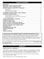
Microprocessor Controlled,
Operation Battery Charger
with Engine Starter
Fully Automatic
Plus Battery and Alternator
Tester
2-AMP
SLOW CHARGE
15-AMP
FAST CHARGE
40-AMP
RAPID
125-AMP
ENGINE
CHARGE
START
FOR 12-VOLT
BATTERIES
Model No,
200,71227
CAUTION:
Read all Safety Rules and Operating Instructions,
and follow them with each use of this product.
Sears_ Roebuck and Co._ Hoffman Estates_ IL 60179 U.S.A.
00-99-000814/0807
/q._:] n=i[o];lifo] _Jill=i_ill_"]
WARRANTY
................................................................................................................
2
IMPORTANT SAFETY INSTRUCTIONS
...................................................................
PERSONAL SAFETY PRECAUTIONS ......................................................................
3
4
BEFORE
5
USING YOUR BATTERY CHARGER
........................................................
Plugging It In .........................................................................................................
Assembling Your Charger .....................................................................................
5
5
Using An Extension Cord ......................................................................................
PREPARING YOUR BATTERY TO BE CHARGED ..................................................
5
5
OPERATING
6
INSTRUCTIONS
...................................................................................
Charging Battery In The Vehicle ...........................................................................
Charging Battery Removed From The Vehicte .....................................................
6
7
Using Engine Start ................................................................................................
USING YOUR BATTERY CHARGER ........................................................................
CHARGER CONTROLS .............................................................................................
7
8
9
CONTROL PANEL GUIDE .......................................................................................
USING THE BUILT-IN BATTERY TESTER ..............................................................
10
11
USING THE BUILT-IN ALTERNATOR TESTER .....................................................
BATTERY PERCENT AND CHARGE TIME ............................................................
12
13
CHARGING TIPS ......................................................................................................
MAINTENANCE AND CARE ...................................................................................
TROUBLESHOOTING
..............................................................................................
14
14
15
PARTS .......................................................................................................................
WIRING DIAGRAM ...................................................................................................
16
16
PLEASE SAVE THIS OWNER'S MANUAL AND READ BEFORE EACH USE.
The DieHard Model 71227 Microprocessor Controlled, Fully Automatic Operation
Battery Charger with Engine Starter Plus Battery and Alternator Tester offers
features to accommodate the needs for home or tight commercial use. This manual
will explain how to use the battery charger safely and effectively. PIease read and
follow these instructions and precautions carefuily.
For information about troubleshooting,
call toII-free from anywhere in the U.S.A.
7 am to 4:30 pm Central Time Monday through Friday. 1-800-SEARS-64
1-800-732-7764).
W/'.Ir,]r,,.'1_IIli'l
THREE-YEAR
FULL WARRANTY
If this Battery Charger faiIs due to a defect in material or workmanship within three
years from the date of purchase, RETURN IT TO ANY SEARS STORE or OTHER
DIEHARD OUTLET IN THE UNITED STATES FOR FREE REPLACEMENT.
This warranty gives you specific legal rights, and you may also have other rights
which vary from state to state.
Sears, Roebuck and Co., Hoffman Estates, IL 60179
2
WARNING - RISK OF EXPLOSIVE GASES
WORKING IN VICINITY OF A LEAD-ACID BATTERY IS DANGEROUS. BATTERIES GENERATE EXPLOSIVE GASES DURING NORMAL BATTERY
OPERATION. FOR THIS REASON, IT IS OF UTMOST IMPORTANCE THAT
EACH TIME BEFORE USING YOUR CHARGER, YOU READ THIS MANUAL
AND FOLLOW THE INSTRUCTIONS EXACTLY.
To reduce risk of battery explosion, follow these instructions and those pubNshed by
battery manufacturer and manufacturer of any equipment you intend to use in vicinity
of battery. Review cautionary markings on these products and on engine.
f-%\v1:1//I 14-'1:I1l f-'t i _tl[et i [el 1f-1
• WARNING: Handling the cord on this
product or cords associated with accessories soId with this product, may
expose you to lead, a chemical known
to the State of California to cause
cancer and birth defects or other
reproductive harm. Wash hands after
handling.
• Read alI instructions and cautions
printed on the battery charger, battery,
and vehicIe or equipment using battery.
• Use charger only on lead-acid type
rechargeable batteries, such as those
used in cars, trucks, tractors, airptanes, vans, RVs, trolling motors, etc.
This charger is not intended to supply
power to a low voltage electrical
system other than in a starter-motor
application.
• Never use charger for charging dry
ceN batteries that are commonly used
with home appliances like radios, stereos, remote controls, etc. These batteries may burst and cause personal
injury.
• Do not disassemble charger. Take it
to a qualified service professional if
service or repair is required. Incorrect
assembly may result in fire or electrical shock.
• To reduce risk of electrical shock,
unplug the charger from the outlet
before attempting any maintenance
cleaning.
or
• Always charge battery in a well-ventilated area.
• WARNING: Battery chargers get hot
during operation and must have proper
ventilation. Air needs to flow around
entire charger. Do not set charger en
flammable materials like carpeting,
upholstery, paper, cardboard, etc.
Charger may damage leather and melt
plastic and rubber.
HELP US HELP YOU --Remember:
Place charger as far away from the
battery being charged as the charger
cables will permit.
Do not expose charger to rain or snow.
Never charge a frozen battery. If battery
fluid (electrolyte) becomes frozen, bring
battery into a warm area to thaw before
you begin charging.
Never allow battery acid to drip on
charger when reading specific gravity or
filling battery.
Never set a battery on top of the
charger.
Never place charger directly above
battery being charged. The gases from
the battery wilI corrode and damage the
charger.
Never touch the battery cIamps together
when the charger is on. You could cause
a spark.
Be sure to position the charger power
cord to prevent it from being stepped on,
tripped over, or damaged.
Never pull out the plug by the cord when
unplugging the charger. Pulling on the
cord may cause damage to the cord or
the plug.
Never operate charger if it has received
a hard blow, been dropped, or otherwise
damaged. Take it to a qualified professional for inspection and repair.
Do not operate the charger if it has a
damaged power cord or plug. Have the
cord replaced.
• Wear complete eye and clothing
protection when working with leadacid batteries.
• Remove all personal metal items
from your body such as rings, bracelets, necklaces and watches, while
'working with a lead-acid battery A battery can produce a short circuit current
high enough to weld a ring (or the like)
to metal, causing a severe burn
• Make sure that someone is within
range of your voice to come to your
aid if needed while you work with or
are near a lead-acid battery.
• Have plenty of fresh water and soap
nearby for use in case battery acid
contacts your eyes, skin, or clothing. If
this happens, wash immediately with
soap and water. Then get medical attention.
• Avoid touching your eyes while
working with a battery. Acid particles
(corrosion) may get into your eyes. If
this occurs, flush eyes immediately
with running cotd water for at least 10
minutes. Then immediately get medical attention.
• Take care not to drop any metal tool
or metal object onto the battery This
may spark or short circuit the battery
or another electrical device that may
cause
an
explosion.
• Always operate the battery charger in
an open, well-ventilated area
• Never smoke or allow a spark or flame
in the vicinity of the battery or engine.
Batteries generate explosive gases.
• Neutralize any acid spills thoroughly
with baking soda before attempting to
clean up.
itisimportant
tounderstand
yourcharger's
requirements.
Thissection
willteIIyouabout
yourcharger's
electrical
requirements
andhowtoprepare
abatteryforcharging.
PLUGGING
ITIN
Wrapclampcablesafterunplugging
the
Yourcharger
requires
a 120V
AC2-prong powercordfromtheACwalloutletand
'wailoutletreceptacle
installed
according storeyourcharger
inadrylocation.
toalIlocalcodes
andordinances.
USING
ANEXTENSION
CORD
Theuseofanextension
cordisnotrecommended.
Ifyoumustuseanextension
cord,pleasemakesurethatyoufollow
theseguideIines:
• Makesurethatthepinsoncharger's
ASSEMBLING
YOURCHARGER
powercordfitfirmlyintotheextension
cord,andthattheextension cord fits
included
withyourbattery
charger
aretwo
firmly into the receptacle.
cordwrapcleatsforstorage
oftheclamp
cables.
• Check that the extension cord is properIy
and in good electrical condition.
Toinstall,
alignthetwotabstocorrespond • 'wired
Make sure that the wire size is large
withthetworeceptacles
andpushuntilyou
enough for its length and for the AC
hearasnap.
ampere rating, as specified in the chart
below.
Length of Cord, in Feet
AWG* Size of Cord
*AWG-American
25
18
50
16
t00
t2
150
10
Wire Gauge
It,,];.t:ll/,.It,tll [_'ti'i{.llJ ;.II:_'._/ll_l_._'_ eEo3-1=1[_]:
r-,q_._]:=lm]
it is important that you read and follow these guidelines while you are preparing to
charge the battery.
• Make sure that you have a 12 volt
lead-acid battery. Determine voltage of
battery by referring to vehicle owner's
manual orthe battery markings. Charge
battery initially at charger's
lowest
rate.
• Take time to read all of the battery
manufacturer's
specific precautions,
such as removing or not removing vent
caps while charging, and recommended
rates of charge.
• Be sure that the area around the battery is well ventilated while it is being
charged. Gas can be forcefully blown
away by using a piece of cardboard or
other nonmetallic material as a fan.
• CIean the batteryterminals. Be careful to
keep corrosion from getting in or around
your eyes or on your hands.
• Wear safety glasses. See additionaP'Personal Safety Precautions" on page 4.
• If required, for batteries with removable
vent caps, add distilIed water to each ceil
until the battery acid reaches the level
recommended bythe manufacturer. This
will help purge excessive gases from the
ceils. Be careful notto overfilI. Ifyou have
a sealed battery with non-removable
vent caps, no action is necessary.
• if it is necessary to remove the battery
from the vehicle to charge it, always
remove the grounded terminal from the
battery first. Turn off all vehicle accessories to avoid sparks from occurring.
• NOTE: A marine (boat) battery installed
in a boat must be removed and charged
on shore.
5
Io] 14 _.!-'1t I1[_]111
f.-'11_.tl[_,ti [o] 1f--1
NOTE: A marine (boat) boat battery must be removed and charged on shore. To
charge it on board requires equipment specially designed for marine use.
IMPORTANT: Follow all safety instructions and precautions when charging your battery. Wear compIete eye protection and clothing protection. Charge your battery in a
well-ventilated area.
CHARGING
VEHICLE:
BATTERY IN THE
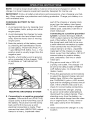
1. Avoid personal injury by keeping clear
of fan blades, belts, pulleys and other
engine parts.
2. Avoid damaging the charger by keeping the power cord and output cords
away from the hood, door or moving
engine parts.
3. Note the polarity of the battery posts
by checking the identification marks
on the battery: POSITIVE (POS, P or
+) and NEGATIVE (NEG, N or -). The
positive post is usually larger than the
negative post.
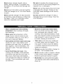
4. Identify which battery post is grounded or connected to the chassis. THIS
IS NORMALLY THE NEGATIVE
POST.
part of the chassis or engine block,
away from the battery (see figure).
DO NOT connect clamp to negative
battery post, carburetor, fuel line or
sheet metal part.
Connecting to a positive-grounded
system: Connect the black (NEGATIVE) output clamp to the NEGATIVE
post of the battery. Rock and twist
the clamp back and forth to be sure
a solid electrical connection is made.
Then connect the red (POSITIVE)
output clamp to a heavy, unpainted
metal part of the chassis or engine
block, away from the battery. DO NOT
connect clamp to positive battery
post, carburetor, fuel line or sheet
metal part.
6. Plug power cord into a 120VAC
2-prong wall outlet. The charger will
be set to the default state of REGULAR battery type, no charge rate
(tester mode).
7. Press the appropriate control buttons
to select the desired charge rate and
battery type. Within a few seconds,
the CHARGING (yellow) LED should
light and the charging process should
start, if the CHECK (red) LED is on,
check for correct cable connections.
NEGATIVE GROUNDED
SYSTEM
5. Connecting to a negative-grounded
system: Connect the red (POSITIVE)
output clamp to the POSITIVE post of
the battery. Rock and twist the clamp
back and forth to be sure a solid
electrical connection is made. Then
connect the black (NEGATIVE) output
clamp to a heavy, unpainted metal
8. To disconnect the charger, unplug
its power cord before attempting to
disconnect the output clamps. Then,
standing away from the battery, remove the output clamp from the chassis or engine block. Finally, remove
the output clamp from the battery
post.
9. Clean and store the charger in a dry
location.
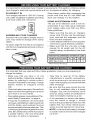
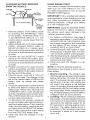
CHARGING BATTERY REMOVED
FROM THE VEHICLE:
POSmVE
BATTERY
NEGATIVE
BATTERY
CHARGER
CORD
__POWER
TO
GROUNDED
POWER
OUTLET
1. Note the potarity of the battery posts
by checking the identification marks
on the battery: POSITIVE (POS, P or
+) and NEGATIVE (NEG, N or -). The
positive post is usually larger than the
negative post.
2. Attach at least a 24-inch-long, 6-gauge
(AWG), insulated battery cable to
NEGATIVE (NEG, N or -) battery post.
Rock and twistthe clamp back and forth
to be sure a solid electrical connection
is made.
3. Connect the red (POSITIVE) output
clamp to the POSITIVE battery post.
Rock and twistthe clamp back and forth
to be sure a solid electricaI connection
is made.
4. Position yourself as far away from the
battery as possible, and then connect
the btack (NEGATIVE) output ctamp to
the free end of the cable.
5. Plug the power cord into a 120V AC
2-prong wail outlet. The charger wilI be
set to the default state of REGULAR
battery type, no charge rate (tester
mode).
6. Press the appropriate controI buttons
to seIect the desired charge rate and
battery type. Within a few seconds, the
CHARGING (yeIIow) LED should light
and the charging process shouid start.
If the CHECK (red) LED is on, check for
correct cabIe connections.
7. To disconnect the charger, unplug its
power cord before attempting to disconnectthe charger cIamps. Then, standing
away from the battery, remove the output clamp from the NEGATIVE battery
post. Finally, remove the output clamp
from the POSITIVE battery post.
8. Clean and store the charger in a dry
location.
USING ENGINE START
Your battery charger can be used to jump
start your car if the battery is low. Foitow these instructions on how to use the
ENGINE START feature.
IMPORTANT: Follow alI safety instructions
and precautions when charging your battery. Wear complete eye protection and
clothing protection. Charge your battery
in a well-ventilated area.
IMPORTANT: Using the ENGINE START
feature WITHOUT a battery installed in
the vehicle could cause damage to the
vehicle's electrical system.
1. For battery connections, see page 6
and foIIow instructions 1-6of CHARGING BATTERY IN THE VEHICLE With
the charger ptugged in and connected
to the battery of the vehicle, set the
CHARGE RATE to 125A START.
2. Crank the engine until it starts or 5 seconds passes. If engine does not start,
wait 3 minutes before cranking again.
3. After theenginestarts, unptugthe power
cord before disconnecting the output
clamps from the battery.
4. Clean and store the charger in a dry
location.
NOTE: During the starting sequence
listed above, the charger is set to one of
three states.
1. Wait for cranking - The charger waits
until the engine is actually being cranked
before delivering 125 amps for engine
start. The charger delivers charge at a
rate of up to 15 amps while waiting and
wiII reset if the engine is not cranked
within 15 minutes. (lfthe charger resets,
it sets itself for REGULAR battery tester
(no charge rate). While waiting for cranking, the digital dispIay shows the battery
voltage (it can't be set to percent).
2. Cranking- When cranking is detected,
the charger will automaticaIly deliver up
to its maximum output (at least 125A) as
required by the starting system for up
to 5 seconds or until the engine cranking stops. The digital display shows a
countdown of the remaining crank time
in seconds. It starts at 5 and counts
down to 0.
3. CoolDown- Aftercranking,
thechargerentersamandatory
3-minute
(180
second)
cooldownstate.Duringthis
period,
nosettings
canbechanged.
The
buttons
areignored.
Thedigital
dispIay
indicates
theremaining
cooldowntime
inseconds.
Itstartsat180andcounts
downto0.The125A
START
LEDblinks
onceevery second. During the cool
down period, no current is delivered to
the battery. After 3 minutes, the 125A
START LED will stop blinking and will
OVERVIEW
Using this battery charger is very simple.
First, connect the battery and AC power
following the precautions
listed under
"OPERATING
INSTRUCTIONS".
Then
seIect the appropriate BATTERY TYPE
and CHARGE RATE for your battery. The
charger will then do everything automatically. This section explains a few details.
CHARGING:
If the charger does not
detect a properly connected battery, the
CHECK (red) LED will light continuously
until such a battery is detected. Charging
will not begin while the CHECK LED is on.
When charging begins, the CHARGING
LED will be Iit.
AUTOMATIC SHUT OFF: When the 2A,
15A or 40A charge rate is selected, the
charger is set to perform an automatic
charge. When an automatic charge is
performed, the charger stops charging
automatically after the battery is charged.
ABORTED CHARGE: If charging can't
be completed normally, charging will be
aborted. When charging is aborted, the
charger's output is shut off and the red
CHECK LED and digital display blink on
and off (at opposite times). In that state, the
charger ignores all buttons. To reset from
after an aborted charge, either disconnect
the battery or unplug the charger.
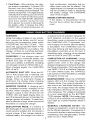
DESULFATION
MODE: If a battery
left discharged for an extended period,
could become sulfated and not accept
normal charge. If the charger detects
sulfated battery, the charger will switch
is
it
a
a
to
light continuously, indicating that another crank cycle can be started. The
digitaI display will change from displaying the countdown back to displaying
the battery voltage. The CHARGING
LED will be lit again.
ENGINE STARTING NOTES:
• If the battery is disconnected during
the cool down period, the charger will
reset.
a special mode of operation designed for
such batteries. Activation of the special
desulfation mode is indicated by blinking
the CHARGING LED. If successful, normal charging will resume after the battery
is desulfated. The CHARGING LED will
then stop blinking and light continuously.
Desulfation could take up to 10 hours, tf
desulfation fails, charging wilI be aborted
and the CHECK (red) LED wilI blink.
COMPLETION OF CHARGING: Charge
completion is indicated by the CHARGED
(green) LED; when lit, the charger has
stopped charging and switched to the Maintain Mode of operation, if the type selected
was DEEP CYCLE or DieHard PIatinum.
For other battery types, the CHARGED
LED comes on 'when the battery is charged
enough for normal use.
MAINTAIN MODE: When the CHARGED
(green) LED is lit, the charger has started
Maintain Mode. This mode of operation is
also known as Float-Mode Monitoring. in
this mode, the charger keeps the battery
fully charged by delivering a small current,
when necessary. The voltage is maintained
at a level determined by the BATTERY
TYPE selected. NOTE: If the battery type
is REGULAR or AGM/Gel, the CHARGED
LED might be lit before Maintain Mode is
started.
GENERAL
CHARGING
NOTES:
The
charger is designed to control its cooling
fan for efficient operation. Consequently, it
is normal for the fan to start and stop when
maintaining a fully charged battery. The fan
does not run in Tester Mode.
Ifthecharge
modeischanged
aftercharg- Thevoltage
displayed
duringcharging
is
inghasstarted
(bypressing
theCHARGE thecharging
voltageandusually
willbe
RATEor BATTERY
TYPEbutton),the higher
thanthebattery's
resting
voltage.
charging
process
willberestarted.
I[o];r-,_=T_=1[_[_o] #bd;[o]_,.'-]
"marine". Deep cycle batteries are usually larger than the other types.
• AGM/GEL: AGM and geI ceil batteries
have sealed cases without vent caps.
Such batteries are often smaller than
the other types.
• DIEHARD PLATINUM: Select the DieHard Platinum battery type if your battery
is a DieHard Platinum battery. NOTE:
When DieHard Platinum is selected, the
default charge rate wilI be 40A RAPID.
With the exception of AGM and gel cell
batteries, alI other battery types may or
may not have vent caps. Vent caps are
located on top of the battery and provide e
means to add distilled waterwhen needed.
71227 CONTROL PANEL
DISPLAY MODE SWITCH
Use this switch button to set the function of
the digital display to one of the following.
• BATTERY %: The digital display shows
an estimate of the percent of charge of
the battery connected to the charger
battery clamps.
• VOLTAGE: The digital display shows the
voltage at the charger battery clamps in
DC volts.
• ALTERNATOR %: The digital display
shows an estimated percentage of the
output of the vehicle charging system
connected to the charger battery clamps
as compared to a properly functioning
system.
BATTERY TYPE SWITCH
Use this switch button to set the type of battery to be charged to one of the following.
• REGULAR: This is the type of battery
usually used in cars, trucks, and motorcycles. These batteries have vent caps
and are often marked "low maintenance"
or "maintenance-free".
• DEEP CYCLE: Deep cycle batteries
are usually marked as 'deep cycle" or
Batteries shouid be marked with theirtype.
If charging a battery that is not marked,
check the manual of the item that uses
the battery. If the battery type is unknown,
use the REGULAR setting. Make sure the
battery complies with the safety instructions on page 3.
CHARGE RATE SWITCH
Use this switch button to set the charge
rate to one of the following.
• 2ASLOW CHARGE RATE: Intended for
charging smatl batteries such as those
commonly used in garden tractors, snow
mobiles and motorcycles. The 2A rate
is net intended to be used as a trickle
charger for larger batteries.
• 15A FAST or 40A RAPID CHARGE
RATE: Use for charging automotive
batteries, marine batteries, and deep
cycle batteries. Net intended for industrial
applications.
• 125A START: Provides 125 amps for
cranking an engine with a weak or run
down battery. Always use in combination
with a battery.
• OFF/TEST: Intended for testing instead
of charging a battery. The four charge
rate LED's all stay off. NOTE: If DieHard
Platinum has been selected, the default
charge rate will be 40A RAPID.
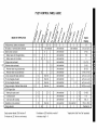
71227 CONTROL
PANEL GUIDE
4
MODE OF OPERATION
Initial power-up,
baftery
No battery or reversed
Digital
Display
User selected
Battery tester activated
Battep] tester with charged
Battmy
battery
o
o
tester with no battery
User selected
O
User selected
O
2 Amp charge with battery
15 Amp charged
activated
40 Amp charged
activated
Charge
- Maintain
complete
125A Engine
O
o
o
o
o
detected
Mode started
O
User selected
O
User selected
O
User selected
User selected
User sel
User selected
User sel
User selected
User sel
User selected
O
engine
B
Usersel
B
aborted
Empty spaces indicate
O indicates
I
I
00
User selected
0(%) or 00(V)
0-100
100
O
00~170
0~199
85~130
0-84,131 ~ 199
O
xx(%) or xx x(V)
O
xx(%) or xx x(V)
xx(%) or xx x(V)
100(%) or xx x(V)
O
Start
Cool down after cranking
Desulfation mode activated
Cha_e
I
User selected
O
User sel
Waiting for engine crank
Cranking
I
User selected
O
tester on good alternator
tester on bad alternator
I
User selected
O
Voltage meter activated
Alternator tester activated
Alternator
Alternator
I
Ioi
O
O
not detected
battery detected
LEDs that are off
an LED that is on continuously
I
User selected
O
User selected
O
5 ÷0
User selected
B
180 90
User selected
I
B indicates
an LED that blinks on and off
x indicates
a digit 0 - 9
I
User selected
I
I
* display
I
1 0-160
15(%)or16(V)
*bad bat(B)
blinks "bad" then r'bat" repeatedly
La[_-,)
I_[c]ad-i=m:Lnnj
Imid I_II:T._iald=1z_h"dfi
d=[...'.,]u
d=1z_
OVERVIEW
powered up, the charger will remain a
tester (not a charger) indefinitely, unless
a charge rate is selected.
This battery charger has a built-in battery
tester that displays either an accurate
battery voItage or an estimate of the
battery's relative charge based on the
battery voItage and the Battery Council
International scale.
TESTING AFTER CHARGING
After the charger has been changed from
tester to charger (by selecting a charge
rate), it remains a charger. To change
the charger back to a tester, press the
CHARGE RATE switch until atl CHARGE
RATE LEDs are OFR
TESTING SEQUENCE
There are four basic steps required to
use the 71227 as a battery tester.
1. Connect the charger battery clamps to
the battery. Be sure to follow all of the
precautions listed under 'OPERATING
INSTRUCTIONS".
2. Connect the charger power cord to a
120V AC 2-prong wail outlet. Again,
be sure to follow all of the precautions
listed under "OPERATING INSTRUCTIONS".
3. If necessary,
press the BATTERY
TYPE button until the correct type is
indicated.
4. Read the voltage on the digital disptay
or press the display mode button to set
the tester to BATTERY % and read the
TESTER STATUS LEDs
When the 71227 is operating as a battery tester, the status LEDs tight under
the following conditions:
• The CHARGED (green) LED wilI tight if
a charged battery is tested.
• The CHARGING (yellow) LED does net
Iight in the battery test mode.
• The CHECK (red) LED lights unless a
properly connected battery is detected.
• When the tester display mode is set to
VOLTAGE, the CHARGED and CHARGiNG LEDs won't light.
INITIAL PERCENT CALCULATION
When a battery % is caIcuIated for the
first time after connecting a battery, the
digital display 'will show three dashes
('---") for a period as long as several
seconds while the tester anaIyzes the
battery.
battery percent.
TESTER AND CHARGER
When first turned on, the 71227 operates only as a tester, not as a chargen To
continue to use it as only a tester, avoid
pressing the CHARGE RATE switch button. Selecting a charge rate activates the
battery charger and deactivates the tester.
Pressing the CHARGE RATE button when
the 125A Sta4 LED is lit (except during
the 180 second cool down) will shut off
the charger and activate the tester.
POWER-UP
NOTES FOR TESTING BATTERY %
A recently charged battery could have a
temporarily high voItage due to what is
known as "surface charge". The voltage of such a battery will gradually drop
during the period immediately after
the charging system is disengaged.
Consequently, the tester could display
inconsistent values for such a battery.
For a more accurate reading, the surface
charge should be removed by temporarily creating a load on the battery, such as
by turning on lights or other accessories.
IDLE TIME LIMIT
If no switch button is pressed within 15
minutes after the charger is first powered
up, the charger will automatically switch
from tester to charger, if a battery is
connected. In that case, the charger will
be set for the 2A charge rate and 12V
REGULAR battery type.
The battery % ranges from 0 to 100.
The battery tester is only designed to
test batteries. Testing a device with a
rapidly changing voltage could yield
unexpected or inaccurate results.
TESTER WITHOUT TIME LIMIT
If either the DISPLAY MODE or BATTERY TYPE button is pressed within
the first ten minutes after the charger is
11
_l[-_i_[Ltl/:l_
:]ljllllHl_|;lill:lz_;_il[O]Z_
id::_"]ld::lZ_
TESTER STATUS LEDs
When the 71227 is operating as an alternator tester, the status LEDs light under
the following conditions.
This battery charger has a built-in alternator tester that dispIays either an accurate alternator voltage or an estimate of
the alternator's relative output compared
to normal alternators. The Alternator %
• The CHARGED (green) LED will light
if the output of the charging system is
at the normally desired level.
• The CHARGING (yellow) LED does
not light in the alternator test mode.
values displayed should be taken as
general reference, not precise diagnosis.
The alternator tester functions the same
as the battery tester (see previous section of this manual for details) with a few
differences.
• The CHECK (red) LED lights if the
VOLTAGE is much higher or lower
than normally desired.
• When the tester display mode is set
to VOLTAGE, the CHARGED and
CHARGING LEDs won't light (it could
be testing a battery or an alternator).
TESTING SEQUENCE
There are three basic steps required to
use the 71227 as an alternator tester.
1. Connect the charger battery clamps to
the battery or charging system. Be sure
to follow all of the precautions listed
under "OPERATING INSTRUCTIONS".
ALTERNATOR TESTING NOTES
• The alternator percent display can
range from 0 to 199.
• The DISPLAY MODE cannot be setto
ALTERNATOR % during charging.
2. Connect the charger power cord to a
129V AC 2-prong wall outlet. Again, be
sure to foIIow all of the precautions listed
under "OPERATING INSTRUCTIONS".
3. Start the vehicle and turn on the
vehicle's headlights. Read the voltage
on the digital dispIay or press the
DISPLAY MODE button to set the
tester to ALTERNATOR % and read
the alternator percent.
t2
This charger adjusts the charging time in
order to charge the battery completeIy,
efficiently and safeIy. The microprocessor automatically makes the necessary
decisions. However, this section incIudes
guideIines that can be used to estimate
charging times.
There are some important facts to keep
in mind when charging a battery.
When the display indicates 77%
charged, the battery has been charged
enough to start most vehicIes and has
already been charged as much as by
many other battery chargers.
The duration of the charging process
depends on three factors:
When the display indicates 85%
charged, the battery has already been
charged at least as much as by most
other battery chargers.
1. Battery State - If a battery has only
been slightty discharged, it can be
charged in less than a few hours.
The same battery could take up to 10
hours if very weak. The battery state
can be estimated by using the built-in
tester (see page 11). The lower the
reading the longer charging will take.
The battery % shown in tester mode
is an estimate based on the battery voltage and the Battery Council
international scale. The battery %
shown in charger mode is an estimate
of the relative charge in the battery
compared to the charge it should have
if the charging process is allowed to
complete.
2. Battery rating -A higher rated
battery will take longer to charge
than a lower rated battery under the
same conditions. A battery is rated in
ampere-hours (AH), reserve capacity
(RC) and cold cranking amps (CCA).
The lower the rating the quicker the
battery will be charged.
The battery % shown in tester mode
can be used to estimate the relative
charge time. The lower the % shown,
the longer the charge time for a given
battery.
3. Charge rate - The charge rate is
measured in amps. This charger
provides charge rates of 2A, 15A
and 40A. The 125A rate is for engine
start only. The 2A rate is for charging smaller batteries such as those
used for motorcycles and garden
tractors. Such batteries should not be
The battery % shown in charger mode
is an indication of the relative progress
of the charging process. The higher
the battery % displayed, the less
charge time remains.
The more a battery is discharged,
the faster it absorbs charge from a
charger. That means that the battery
% increases faster at the beginning
of the charging process than at the
end. In other words, it takes longer
for the battery to absorb the last few
percent of charge than the first several
percent.
charged using the 15A or 40A rate.
The 15A and 40A rates are for charging larger batteries. In the 40A mode,
the charger begins at a tow-charge
rate and increases-the charge rate if
it is determined that the battery can
accept the higher rate. All charging
modes will decrease the charge rate
as the battery approaches maximum
charge. After the charging process
has started, the digital display can be
used to determine charging progress
by selecting the BATTERY % mode.
t3
Read this entire manual before using your charger. The tips below serve only as a
guide for specific situations.
If your vehicle won't start: You don't
need to fully charge a battery to star[
your vehicle. If the charger won't start
your vehicle using the 125A START rate,
try charging the battery using the 40A
rate for 10 or 15 minutes. That should
charge the battery enough to allow the
125A START rate to star[ the vehicle, tf
the vehicle will then be operated continuously for an extended period (such as
a long drive), the vehicle could charge
the battery back to normal during that
period. If the vehicle wilI only be operated for a short period (short drive), the
battery might need to be charged again
before it could star[ the vehicle again.
Reviving your battery: If you only wish
to charge your battery enough to operate your vehicIe, you don't need to wait
for the entire charging process to be
completed. When the charger displays a
battery % of 77 or more (see page 13),
the battery has usually been charged
enough for the vehicle to start and operate normally.
Completing an interrupted charge: If
the charging process has been interrupted and restarted after the charger
dispIays a battery % 0f85 or more, the
charger could go straight to Maintain
Mode (see page 8). However, if the
original charge was started using 40A,
the charge can often be compIeted using
the 2A rate.
A minimal amount of care can keep your battery charger working properly for years.
1. Clean the clamps each time you are finished charging. Wipe off any battery fluid
that may have come in contact with the clamps to prevent corrosion.
2. Coil the input and output cords neatly when storing the charger. This will help prevent accidental damage to the cords and charger.
3. Occasional cleaning of the case of the charger with a soft cloth will keep the finish
shiny.
t4
I / P.(l]+lJ:| ! ::_']"[.Iei t I+[_
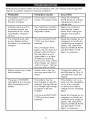
Performance probtems often can be corrected by the user. Please read through this
chart for a possible solution to common problems.
PROBLEM
POSSIBLE
CAUSE
SOLUTION
The battery is connected
and the charger is on,
but isn't charging.
The charger is in tester
mode, not charger mode.
indicator lights are lit in
an erratic manner not
explained in the "Using
Your Battery Charger"
section.
You might have accidentally activated a special
diagnostic mode.
Make sure nothing is
touching the control
panel, then unplug the
charger and plug it in
again.
The CHECK (red) LED
always flashes before
the battery is completely
charged.
The incorrect BATTERY
Reset the charger by unplugging it or briefly disconnecting the negative
battery clip. Select the
desired CHARGE RATE
and BATTERY TYPE
Press the CHARGE
RATE button to activate
charging and select a
charge rate.
TYPE may have been
selected.
This will happen if the
battery did not reach fuII
charge within 24 hours.
May be due to a very
large battery or a bank
of batteries requiring
more power than a 40/15
Amp charger can deliver
within 24 hours. The bat-
again, if necessary.
tery may also be faulty.
Engine crank time is less
than specified.
Starter motor may be
drawing more than 125
Amps.
Charge the battery at
the 40A rate for 10 to 15
minutes then crank the
engine.
The green CHARGED
LED lights a few minutes
after connecting to the
battery.
The battery may be
fuNy charged or recently
charged, teaving the battery voltage high enough
to appear to be fully
charged.
If the battery is in a vehicle, turn the headlights
on for a few minutes
The incorrect BATTERY
Reset the charger by unplugging it or briefly disconnecting the negative
battery clip. Select the
desired CHARGE RATE
and BATTERY TYPE
TYPE may have been
selected.
to reduce the battery
voltage and try charging
again.
again, if necessary.
t5
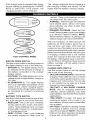
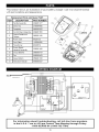
This section shows an illustration of your battery charger. Use it to become familiar
with part locations and appearance.
Replacement Parts List Sears 71227
ITEM
DESCRIPTION
PART NUMBER
1
HandleAssembly
2299001477
2
Case Top
3799004060
3
Faceplate
0899002635
4
ControlBoardAssernNy 2299001600
5
Output CaNesaad
Ctamps
3899001198
6
PowerCord
90026135
7
Cord Cleat
1199004390
8
Transformer
93026579
9
10
PowerBoard/
HeatsinkAssembly
G
2299001482
Circuit Breaker
3999000104
11
Fan
0099000453
12
Case Bottom
3699001330
13
instructionManual
0099000537
kv,
vtIr,iI#[_]1I] r.*_[_r,_r,.12j
I
For information
about troubleshooting,
call toll-free from anywhere
in the U.S.A. 7 am to 4:30 pm Central Time Monday through Friday.
1-800-SEARS-64
(1-800-732-7764).
16