1
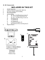
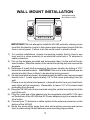
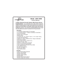
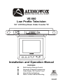
®
ELECTRONICS CORP.
VE-560
Low Profile Television
5.6” LCD Drop Down Under Counter TV
OPEN
POWER
TIME SET
F
TIME ADJUST
G
SENSOR
®
ELECTRO NI CS CO RP .
F
TV/AV1/AV2 AUTO PROG PICTURE
VOLUME
G
TV CHANNEL
Installation and Operation Manual
FEATURES
n
n
n
n
n
Multi-function Remote Control
Automatic Channel Programming
Cable Ready 125 Channel Tuner
Internal Stereo Speakers
Wall or Under Cabinet Mounting
F o r C u s tom e r S e rv ic e
V is it O u r W e b s ite A t
999.audiovox.com
P ro d u c t In fo rm a tio n , P h o to s ,
FA Q ’s O w n e r ’s M a n u als
128-6317
NOTE: This Page Left Blank Intentionally
IMPORTANT SAFETY INFORMATION
A. Precautions
1) Unplug the unit before cleaning. Do not use liquid cleaners or aerosol cleaners. Use a damp cloth for cleaning.
2) Use only Audiovox approved accessories.
3) Do not install this video product where it is likely to be exposed to water.
4) Do not obstruct the slots and openings in the cabinet. They are provided for
ventilation and are necessary to ensure reliable operation of the TV and to
protect it from overheating. This TV should never be placed near or over a
radiator or heat register. This TV should not be placed in a built-in installation
such as a bookcase or rack unless proper ventilation is provided.
5) This TV should be operated only with the AC / DC adapter provided.
6) Do not overload electrical outlets or use extension cords as this can result in
a risk of fire or electric shock.
7) Never push objects of any kind into this TV through openings as they may
touch dangerous voltage points or short-circuit parts that could result in a fire
or electric shock. Never spill liquid of any kind on the TV.
8) Do not attempt to service this TV yourself as opening or removing
covers may expose you to dangerous voltage or other hazards. Refer
all servicing to qualified service personnel.
9) Unplug this TV from the outlet and refer servicing to qualified service personnel under the following conditions:
a) When the power-supply cord or Adapter is damaged.
b) If liquid has been spilled, or an object has fallen into the TV.
c) If the TV has been exposed to water.
d) If the TV does not operate normally when following the operating instructions.
e) If the TV has been dropped or the cabinet has been damaged.
128-6317
B. Kit Components
INCLUDED IN THIS KIT
1
2
3
4
5
VE-560 Television
Audiovox Remote Control (PN 1361613)
AC Power Adapter (PN 1541096)
Mounting template
Hardware Bag
A
10 - 32 x 2 1/2 Mounting screws (4)
B
10 - 32 x 3/4 Mounting screws (4)
C
10 - 32 x 1 3/4 Mounting screws (4)
D
3/4” Spacer (4)
E
1/2” Spacer (4)
F
1/4” Spacer (4)
G
Countersunk washer (4)
H
Self Adhesive Wire mounting clip (2)
Dipole Antenna
6
!
#
A
AUDIO OX
B
"
C
D
G
E
H
F
$
TOOLS REQUIRED
Philips head screwdriver
Centerpunch
1/4” Drill bit
Electric Drill
Adhesive Tape
1
C. Installation
UNDER CABINET INSTALLATION
Cabinet or Shelf
Bottom Edge Molding
1) Choose an appropriate mounting location underneath a cabinet or shelf. Close
proximity to an electrical outlet and a TV antenna or cable connection will
facilitate a neat, easy installation. Do not mount the VE-560 above a range
or oven. Be sure that the location chosen will provide adequate access to
the electrical connectors on the rear of the unit before continuing.
2) If the location chosen has bottom edge molding it may be necessary to use
the mounting spacers provided to effectively lower the VE-560’s front panel
below the molding. Measure the distance between the bottom of the molding and the bottom of the cabinet. A maximum measurement of 1.5” can be
accommodated without using spacers. For larger moldings choose a combination of spacers which will reduce the mounting depth to 1.5” or less.
3) Measure the thickness of the bottom of the cabinet or shelf and the spacers
chosen. Select the shortest screw length which will pass through the countersunk washer, kitchen cabinet and spacers with between 1/4” and 1 1/2”
inches to spare
4) Cut out the template supplied and tape it in place onto the cabinet surface to
be drilled. Center punch the four holes indicated on the template and remove the template.
5) Carefully drill four 1/4” holes at the locations marked above. Place the screws
chosen through the countersunk washers and then through the holes from
the top down.
6) Screw the appropriate spacers on to the screws first, then position the VE560 and screw it in place using its threaded holes.
7) Plug the AC Power adapter into a nearby electrical outlet and into the receptacle marked DC 12V input at the rear of the VE-560
8) Connect your TV antenna or cable system to the antenna connector on the
rear of the VE-560.
9) Route the wires safely away from heat and moisture sources and secure
them in place using the self adhesive wire mounting clip provided.
2
128-6317
WALL MOUNT INSTALLATION
Vertical Mounting
Slot (Rear of Unit)
IMPORTANT!! Do not attempt to install the VE-560 vertically, unless you are
sure that the electric circuits in the chosen area have been turned off at the
fuse or circuit panel. Failure to do this could result in electric shock.
1)
2)
3)
4)
5)
6)
8)
9)
For vertical installations, choose a mounting location that is close to eye
level and is in close proximity to an electrical outlet and a TV antenna or
cable connection.
Cut out the template provided and temporarily tape it to the wall at the desired location. Mark the center of the vertical mounting slot and remove the
template.
Determine if a wall stud is present at the chosen location by drilling a 1/16”
hole at the marked location. CAUTION!! If this unit is to be installed near an
electrical outlet, there is likely to be electrical wiring present.
If a structural stud is present, a suitable length drywall screw can be screwed
directly into it. Leave approximately 1/4” of the screw protruding from the
wall.
If there is no structural stud present, a drywall anchor from your local hardware store will be necessary. Remember to leave 1/4” of its screw head
protruding from the wall.
Hang the VE-560 onto the screw head using the vertical mounting slot at the
rear of the unit.
Plug the male end of the adapter into the receptacle marked DC 12V input
on the bottom of the VE-560 and AC Power adapter plug into a nearby electrical outlet.
Connect your TV antenna or cable system to the antenna connector on the
bottom of the VE-560
Route the wires safely away from heat and moisture sources and secure
them in place using the self adhesive wire mounting clip provided.
3
C. Positioning Screen
To release the screen from its locked position, press the OPEN button located on
the front panel this will unlock the screen and it will swing downward. Pivot the
screen forward until a comfortable viewing angle is reached. The screen may
also be rotated from side to side. NOTE: Do not force the screen beyond its
rotational limit of fifteen degrees. In vertical mount applications it is not necessary to release and position the screen.
D. Controls/Indicators on the Unit
1. OPEN BUTTON
2. TIME SET BUTTON
3. TIME ADJUST UP/DOWN
BUTTONS
4. TIME AM/PM DISPLAY
5. TIME DISPLAY
6. REMOTE CONTROL SENSOR
7. POWER BUTTON
8.TV/AV1/AV2 SELECT BUTTON
9. AUTO PROGRAM BUTTON
10. PICTURE SELECT BUTTON
11. VOLUME UP/DOWN BUTTONS
12. TV CHANNEL UP/DOWN BUTTONS
E. Rear Panel Connections
1. DC 12V INPUT
Plug the male end of the supplied adapter into this jack, then plug the other
end into your AC power outlet. NOTE: Never disconnect the cord from the unit
before the plug is removed from the wall outlet.
4
128-6317
2. LINE OUT
This is a standard 1/8 stereo jack that provides a fixed low level output.
3. DC 12V OUTPUT
You can connect this jack to an Audiovox VC-6000 Wireless Camera Receiver.
4. AUDIO R INPUT 1, AUDIO L INPUT 1, VIDEO INPUT 1
AUDIO R INPUT 2, AUDIO L INPUT 2, VIDEO INPUT 2
For input of an external A/V source such as video game, camcorder, digital
camera etc. Always match the color-coded cable to the appropriate jacks:
Yellow (video) to Yellow, White (left audio) to White, and Red (right audio) to
Red. You can press TV/AV1/AV2 to select the audio and video source.
5. EXTERNAL TV ANTENNA JACK
You can input your CATV into this jack for receiving CATV stations.
F. TV Operation
1. Press TV/AV1/AV2 to select the TV mode or AV1/AV2.
2. Press TV/CATV to select the type of signal you receive, When using an
antenna, adjust it to its best extension, angulation and direction to optimize
the image and sound. When using cable, connect the cable to the external
antenna jack, and press TV/CATV on the remote control to select STD, HRC
or IRC (see Remote Control section). STD is used by most cable systems,
however, if the STD setting does not work with your TV, try the other settings
and/or check with your cable service provider.
3. Pressing AUTO PROG, the TV’s tuner will scan the entire range of the selected band and memorize all the active channels in your area.
4. Press TV CHANNEL UP/DOWN or use the number buttons for TV to select
any active channel.
5. Press VOLUME UP/DOWN to raise or lower the sound level.
6. If the picture needs to be adjusted, press PICTURE to illuminate the onscreen display for contrast, brightness, color and tint in sequence, and press
+/- to adjust each function up/down.
7. Press MUTE to cut off the sound, and the screen will display the volume
adjustment bar for six seconds to indicate that the sound has been turned off.
Press MUTE again to restore sound to the sound level set previously. You can
also release the mute feature by pressing VOLUME UP/DOWN.
5
G. Clock Operation
1. Connect the power to the unit, the LCD in the front panel will display the
time.
2. Press the TIME SET button once (the hour will start to blink) press TIME
ADJUST up/down direction buttons to adjust the hour, press TIME SET again
(the minute will start to blink) press TIME ADJUST up/down direction buttons
to adjust the minute. When the correct time is entered, press TIME SET again
to set time.
H. Remote Control
The remote control will operate Audiovox Televisions and Video Cassette Players.
It is not a universal remote control and will not control equipment from other
manufacturers.
If a universal remote control is to be used with the VE-560, choose the remote
encoding scheme for Audiovox Televisions when programming the remote.
1. TV/VIDEO
Press this button to select the TV mode or AV1/AV2.
2. POWER ON/OFF
Press this button to turn on the TV. The channel number or current video
source will be displayed on screen, and the picture will appear in a few seconds.
Press the button again to turn the TV off.
3. NUMERICAL BUTTONS
Use these buttons to make a direct channel selection. The channel number
chosen will be displayed on the screen for 4 seconds. Channel selection is
carried out with 0-9 keys (0-99ch) and “1—“ key when in cable mode (100125ch).
6
128-6317
4. SKIP/SEARCH BUTTON
This button selects between SKIP and SEARCH mode. In “SKIP mode” the
TV only stops on channels that are programmed into memory when the CHANNEL UP/DOWN buttons are used. When SKIP mode is off, the TV is in
search mode and will stop on all active channels.
a. Press this button until SKIP MODE ON is displayed on the screen. Then
when the channel up and down keys are used, the TV will stop only on the TV
channels stored in memory.
b. Press this button until SKIP MODE OFF is displayed on the screen. Then
all the TV channels will be shown using the channel up and down keys.
5. TV/CATV
Press this button to select the regular 69 channel broadcast TV and the 125
Channel Cable TV (Standard Cable, HRC Cable, and IRC Cable) with the on
screen display.
6. MUTE
Press this button to cut off the sound, and the screen will display the volume
adjustment bar for six seconds to indicate that the sound has been turned off.
Press this button again to restore sound to the sound level set previously. You
can also release the mute feature by pressing VOLUME UP/DOWN.
7. CHANNEL UP/DOWN
Use these buttons to advance to the next higher or lower channel.
8. VOLUME UP/DOWN
Use these buttons to raise or lower the sound level. They are also used to
make picture adjustments in picture select mode.
9. AUTO MEMORY
Pressing AUTO PROG, the TV’s tuner will scan the entire range of the selected band and memorize all the active channels in your area.
10. PICTURE SELECT Each time this button is pressed, the on screen picture
adjustment display cycles through “adjustment bars” for CONTRAST, BRIGHTNESS, COLOR and TINT. Once the desired adjustment bar is displayed, use
7
the VOLUME UP/DOWN buttons to adjust the setting. The display will automatically turn off if no adjustments are made within 6 seconds, or if any other
button is depressed.
11. ERASE/WRITE
When tuned to a channel, press this button to store or erase the channel from
memory. The stored channel numbers are displayed in “GREEN” on the
screen, and the non-stored channel numbers are in “RED”. When using the
CHANNEL UP/DOWN buttons, with the skip mode on, the VE-560 will tune
only to the stored channels .
The following buttons are used for the connected Video Cassette Player (VCP)
that can be supplied by Audiovox’s detailers.
I. REMOTE CONTROLLED VIDEO CASSETTE PLAYER
FUNCTIONS
The VE-560’s remote control incorporates functions for operating an optional
Audiovox VCP. Due to the directional nature of infrared remote controls, be
certain to point the remote control at the sensor on the VCP, when attempting to
control it. These features can only be used with Audiovox Video Cassette Players.
When using another brand VCP, its own remote control must be used. For more
information regarding the use of VCPs, refer to the associated Owner’s Manual.
12. POWER BUTTON
This button is used to turn the VCP on and off.
13. “REW” REWIND BUTTON
If this button is pushed while the tape is stopped, the tape will rewind. If this
button is pushed while the tape is playing, the VCP will go into rewind
search mode.
14. PLAY BUTTON
Press this button to activate play mode while a tape is loaded into the VCP.
This button may also be used to disengage search and pause modes.
15. “F.FWD.” FAST FORWARD BUTTON
If this button is pushed while the tape is stopped, tape will fast forward. If
this button is pushed while the tape is playing, the VCP will go into fast
forward search mode.
16. REPLAY BUTTON
Pressing this button will rewind tape and immediately begin playback when
the tape is fully rewound.
17. STOP BUTTON
Press this button to stop the tape.
8
128-6317
J. Battery Installation
a. Turn the Remote Control face down. Press the ridged area of the battery cover
and slide it off in the same direction as the arrow.
b. Install two AAA batteries. Make sure that proper polarity (+/-) is observed.
c. Slide back the cover in the contrary direction as the arrow until it clicks.
a.
b.
c.
K. CHANNEL TUNING SET UP
In addition to normal broadcast reception of VHF and UHF channels, if you are a
Cable TV subscriber, your new TV is capable of receiving many unscrambled
Cable channels without the use of a converter box. When set to Broadcast TV it
receives CH2-CH69. When set to one of the CATV modes (STD, HRC, or IRC) it
receives CH1-CH125. Follow this simple procedure to make channel tuning more
convenient.
1. Use the TV/CATV button on the Remote Control to select the broadcast or
cable system appropriate for your home. The system selected will be displayed
on the screen. If you have an external roof mounted or rabbit ear antenna,
select “TV,” if you have CABLE TV, select either “STD”, “HRC” or IRC (“STD”
is used by the majority of Cable Systems. Check with your cable system
operator).
2. Press the AUTO MEMORY button on the Remote Control Unit or the TV.
You will see the TV cycle through all channels. The built-in Microprocessor
will automatically store each channel that is actively broadcasting in your
area.
3. To view only strong clear channels, press the SKIP/SEARCH button on the
Remote Control Unit until “SKIP MODE ON” is displayed on the bottom of
the screen. The TV will now tune only to strong, active channels, when the
UP or DOWN buttons are used on the monitor or remote control.
To view a weak or marginal channel, press the SKIP/SEARCH button on the
Remote Control Unit until “SKIP MODE OFF” is displayed on the bottom of
the screen. Tune to the desired channel using the CHANNEL UP/DOWN
button or go directly to the channel by direct access using the 0-9 buttons on
the Remote Control.
4. To ERASE a channel, press the ERASE/WRITE button on the Remote Control
Unit until “MANUAL MEMORY XX ERASE” is displayed on screen. To
STORE a channel, press the button until “MANUAL MEMORY XX ADD” is
displayed on screen.
9
L. Specification
System:
Screen Size:
Illumination:
Bachlighting Life Expectancy:
Resolution:
Pixel Configuration:
Remote Control:
Antenna:
TV Channel:
(CATV)
Audio Output:
Power Supply:
Power Consumption:
Operating Humidity:
Operating Temperature:
Storage Temperature:
NTSC
5.6 Inches
Edge Light Tube
10,000 Hrs.
RGB Stripe
Infrared Rays
Telescopic Antenna, External Antenna Jack
2-6 (VLF Band), 7-13 (VHF Band), 21-69 (VHF
Band),
1-125
2 x 1.5W/80ohm(MAX)
13.5V/1.5A
14W
10-75%
41-140 Degrees Fahrenheit (5-40) Centigrade
4-140 Degrees Fahrenheit (-20-60) Centigrade
10
128-6317
TROUBLESHOOTING
Problem
Solution
Poor Reception
Verify Tuner setting matches
Antenna / Cable broadcast
system. Try other system types
with the TV/CATV BUTTON of the
remote control.
Remote control will not function
Verify that the sensor on the VE560 is not obstructed.
Verify that the infrared LED on
the transmitter is not obstructed.
Check the condition of the
remote control batteries.
Black and White Reception
Verify Tuner setting matches
Antenna / Cable broadcast
system. Try other system
11
NOTE: This Page Left Blank Intentionally
128-6317
90 DAY LIMITED WARRANTY
Applies to Audiovox Video Products
AUDIOVOX ELECTRONICS CORP. (the Company) warrants to the original retail purchaser of
this product that should this product or any part thereof, under normal use and conditions, be
proven defective in material or workmanship within 90 days from the date of original purchase,
such defect(s) will be repaired or replaced with reconditioned product (at the Company's
option) without charge for parts and repair labor.
To obtain repair or replacement within the terms of this Warranty, the product is to be delivered
with proof of warranty coverage (e.g. dated bill of sale), specification of defect(s),
transportation prepaid, to the Company at the address shown below.
This Warranty does not extend to the elimination of externally generated static or noise, to
correction of antenna problems, to costs incurred for installation, removal or reinstallation of
the product, or to damage to tapes, discs, speakers, accessories, or electrical systems.
This Warranty does not apply to any product or part thereof which, in the opinion of the Company,
has suffered or been damaged through alteration, improper installation, mishandling, misuse,
neglect, accident, or by removal or defacement of the factory serial number/bar code label(s).
THE EXTENT OF THE COMPANY'S LIABILITY UNDER THIS WARRANTY IS LIMITED TO THE
REPAIR OR REPLACEMENT PROVIDED ABOVE AND, IN NO EVENT, SHALL THE COMPANY'S
LIABILITYEXCEEDTHEPURCHASEPRICEPAIDBYPURCHASERFORTHEPRODUCT.
This Warranty is in lieu of all other express warranties or liabilities. ANY IMPLIED WARRANTIES,
INCLUDING ANY IMPLIED WARRANTY OF MERCHANTABILITY, SHALL BE LIMITED TO THE
DURATION OF THIS WRITTEN WARRANTY. ANY ACTION FOR BREACH OF ANY WARRANTY
HEREUNDER INCLUDING ANY IMPLIED WARRANTY OF MERCHANTABILITY MUST BE
BROUGHT WITHIN A PERIOD OF 30 MONTHS FROM DATE OF ORIGINAL PURCHASE. IN NO
CASE SHALL THE COMPANY BE LIABLE FOR ANY CONSEQUENTIAL OR INCIDENTAL
DAMAGES FOR BREACH OF THIS OR ANY OTHER WARRANTY, EXPRESS OR IMPLIED,
WHATSOEVER. No person or representative is authorized to assume for the Company any
liability other than expressed herein in connection with the sale of this product.
Some states do not allow limitations on how long an implied warranty lasts or the exclusion or
limitation of incidental or consequential damage so the above limitations or exclusions may not
apply to you. This Warranty gives you specific legal rights and you may also have other rights
which vary from state to state.
U.S.A. : AUDIOVOX ELECTRONICS CORPORATION, 150 MARCUS BLVD.,
HAUPPAUGE, NEW YORK 11788
1-800-645-4994
CANADA : CALL 1-800-645-4994 FOR LOCATION OF WARRANTY STATION SERVING
YOUR AREA
128-5556C
© Copyright 2002 Audiovox Electronics Corp. 150 Marcus Blvd. Hauppauge, NY 11788
128-6317