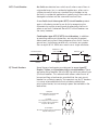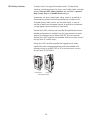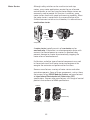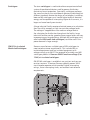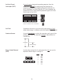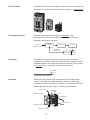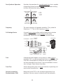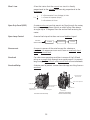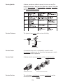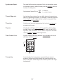
1
Table of Contents
Introduction............................................................................ 2
Siemens Industry, Inc.............................................................. 4
Electric Power......................................................................... 5
Residential Applications........................................................ 10
Commercial Applications....................................................... 20
Industrial Applications........................................................... 37
Manufacturing Applications.................................................. 44
Discrete Parts Manufacturing................................................. 46
Assembly Processes............................................................... 52
Batch and Continuous Processes............................................ 65
Pictorial Glossary................................................................... 71
Review Answers.................................................................. 111
Final Exam Instructions....................................................... 112
Introduction
Welcome to another course in the STEP series, Siemens
Technical Education Program, designed to help our distributors
and customers better understand Siemens Industry, Inc.
products. This course covers Basics of Electrical Products.
Upon completion of Basics of Electrical Products, you should
be able to:
•
Explain how Siemens products are used in basic residential,
commercial, and industrial applications
•
Explain the similarities and differences between load
centers, panelboards, switchboards, switchgear, and
secondary unit substations
•
Identify various Siemens products used in discrete
parts manufacturing, assembly, batch processing, and
continuous processing
•
Identify various Siemens products by trade name
This knowledge will help you better understand product
applications. In addition, you will be better prepared to discuss
electrical products and systems with others. You should
complete Basics of Electricity before attempting Basics of
Electrical Products. Once you have completed Basics of
Electrical Products, you should complete or review any of the
other STEP courses that are relevant to your work. The general
information provided in Basics of Electrical Products will
help you better understand the specific product details in the
remaining STEP courses.
After you have completed this course, if you wish to determine
how well you have retained the information covered, you can
complete a final exam online as described later in this course. If
you pass the exam, you will be given the opportunity to print a
certificate of completion from your computer.
Siemens is a trademark of Siemens AG. Product names
mentioned may be trademarks or registered trademarks of their
respective companies. Specifications subject to change without
notice.
National Electrical Code® and NEC® are registered trademarks
of the National Fire Protection Association, Quincy, MA 021697471.
NEMA® is a registered trademark and service mark of the
National Electrical Manufacturers Association, Rosslyn, VA
22209.
Underwriters Laboratories Inc.® and UL® are registered
trademarks of Underwriters Laboratories Inc., Northbrook, IL
60062-2096.
Other trademarks are the property of their respective owners.
Siemens Industry, Inc.
Company Overview
The objective of this course is to provide a high-level overview
of those products of Siemens Industry, Inc. (SII) which are sold
by our channel partners and fall into the following categories:
low voltage power distribution, motors, control, drives, and
industrial automation. It is beyond the scope of this course to
cover all SII products. For more information on SII products, refer
to the Siemens Industry, Inc. web site.
Before discussing Siemens Industry, Inc. products, it is useful to
briefly discuss our parent company, Siemens AG, and how SII
fits into the Siemens worldwide business structure.
Siemens AG is a leading supplier of electrical and electronic
equipment and associated services worldwide. From the initial
Siemens company, founded in 1847, Siemens has grown
become one of the largest companies with employees in 190
countries, including about 70,000 employees in the U.S.
Siemens AG offers a broad range of products and services
in the following four business sectors: Energy, Healthcare,
Infrastructure & Cities, and Industry.
Siemens AG is headquartered in Berlin and Munich and operates
in most countries through regional cluster organizations. In the
United States, Siemens has a number of operating companies,
such as SII, that each focus on a portion of the total Siemens
portfolio of products and services.
In order to help you better understand SII’s low voltage power
distribution products, motors, control, drives, and industrial
automation, this course looks at where many of these products
fit in the flow of energy in sample residential, commercial, and
industrial applications. Keep in mind that the flow of energy
from the electric utility is discussed only briefly in this course
because utility power generation, transmission, and highvoltage distribution products and services are the responsibility
of Siemens Energy sector companies.
Electric Power
Power, originating at a power generating plant, is distributed
to residential, commercial, and industrial customers through
various transmission lines and substations.
Power Sources
There are several energy sources used to produce electrical
power. For example, coal, oil, and uranium are fuels used to
convert water into steam which, in turn, drives a turbine. Some
utilities also use gas turbines, or, for combined cycle operation,
both gas and steam turbines. The output shaft of the turbine is
connected to an alternating current (AC) generator. The AC
generator is rotated by the turbine. It is the AC generator which
converts the mechanical energy into electrical energy.
Coal
Steam Line
Generator
Steam Turbine
Pulverizer
Boiler
Hydroelectric Power
Hydroelectric power plants use mechanical energy from falling
water to turn a generator.
Newer Renewable Energy
Sources
Of the power generation approaches discussed so far, only
hydroelectric power is a renewable energy source. Hydroelectric
power has been around from the earliest days of electric power
generation. In recent years, a small, but growing, percentage
of electrical energy is generated using wind or solar power or
through a host of other renewable approaches.
AC Generators
Most of the technologies in use today to generate electricity
utilize an AC generator. AC generators operate on the theory
of electromagnetic induction. This simply means that, when
conductors are moved through a magnetic field, a voltage is
induced into the conductors.
Although commercial power generators are complex machines,
for the purpose of explanation, a basic generator can be
constructed of magnets, an armature, slip rings, brushes, and
some type of resistive load. An armature is any number of
conductors wound in loops which rotate through the magnetic
field created by the magnets. For simplicity, one loop is shown
below.
If you track the rotation of the AC generator through a complete
revolution of 360°, you would see that, during the first quarter
of a revolution, voltage increases until it reaches a maximum
positive value at 90°. Voltage decreases during the second
quarter of a revolution until it reaches zero at 180°. During the
third quarter of a revolution, voltage increases in the opposite
direction until it reaches a maximum negative value at 270°.
During the last quarter of a revolution, voltage decreases until it
reaches zero at 360°.
This is one complete cycle of operation. If the armature of this
simple AC generator rotates 3600 times per minute (3600 RPM),
it produces 60 cycles of voltage per second, or 60 hertz.
Energy Transfer
The role of the generator just described is to change mechanical
energy into electrical energy. In order for this energy to be
useful, however, it must be transmitted to the utility’s customers
via transmission lines. The most efficient way to do this is
to increase the voltage while at the same time reducing the
current. This is necessary to minimize the energy lost in heat
2
on the transmission lines. These losses are referred to as I R (Isquared-R) losses because they are equal to the square of the
current times the resistance of the power lines.
Transformers
Once the electrical energy gets near the end user, the utility
steps down the voltage to the level needed by the user. The
device that utilities use to step up the voltage at the generator
end and step down the voltage at the user end is called a
transformer.
The transformer transfers energy from a primary coil to a
secondary coil by mutual induction. The AC generator provides
electrical power to the primary coil. The magnetic field produced
by the primary coil induces a voltage into the secondary coil,
which supplies power to the connected load. The load in this
case is the entire electrical distribution network including all
residential, commercial, and industrial customers.
A step-up transformer is used when it is desirable to step
voltage up from one level to another. The following simplified
example shows a 1:2 step-up transformer could be used to
step 120 volts up to 240 volts. A 2:1 step-down transformer
could be used to step 240 volts down to 120 volts. Keep in
mind that most transformers step up or down the voltage more
significantly than this simple example displays.
1:2
AC
Source
Primary Coil
900 Turns
Secondary Coil
1800 Turns
Load
120 VAC
I = 10 amps
Vload = 240 VAC
Iload = 5 amps
Step-Up Transformer
Three-Phase Voltage
Primary Coil
1800 Turns
240 VAC
I = 5 amps
2:1
Secondary Coil
900 Turns
Vload = 120 VAC
Iload = 10 amps
Step-Down Transformer
For simplicity, the generator and transformers shown so far have
been single-phase devices. While single-phase power is needed
for many applications, utilities generate and transmit threephase power. In a three-phase system, the generator produces
three voltages. Each voltage phase rises and falls at the same
frequency (60 Hz in the U.S., 50 Hz in many other countries);
however, the phases are offset from each other by 120°.
+
Phase A Phase B Phase C
0
-
Three-Phase Transformers
Transformers used with three-phase power require three
interconnected coils in both the primary and the secondary.
These transformers can be connected in either a wye or a delta
configuration. The type of transformer and the actual voltage
depend on the requirements of the power company and the
needs of the customer.
The following illustration shows the secondary of a wyeconnected transformer and the secondary of a delta-connected
transformer. These are only examples of possible distribution
configurations, the specific voltages and configurations vary
widely depending upon the application requirements.
Wye
Delta
A
480 Volts
N
A
480 Volts
120 Volts
B
240 Volts
N
277 Volts
277 Volts
C
120 Volts
480 Volts
B
C
240 Volts
208 Volts
277 Volts
A-B
B-C
C-A
A-N
B-N
C-N
480 Volts
480 Volts
480 Volts
277 Volts
277 Volts
277 Volts
A-B
B-C
C-A
A-N
B-N
C-N
240 Volts
240 Volts
240 Volts
120 Volts
208 Volts
120 Volts
240 Volts
Residential Applications
Power, generated at a power plant and stepped up to a high
transmission voltage, is brought to a local substation. Here, it is
stepped down to a lower distribution voltage. When it reaches
its final destination at a residential customer, it is stepped
down to 240 volts. Only single-phase power is used in a typical
residential application.
Power Supply
The most common supply system used in U.S. residential
applications today is a single-phase, three-wire supply
system. In this system, the voltage between either hot wire and
neutral is 120 volts and the voltage between the two hot wires
is 240 volts. The 120 volt supply is used for general-purpose
receptacles and lighting. The 240 volt supply is used for heating,
cooling, cooking, and other high-demand loads.
Step-down Transformer
Distribution Voltage
Hot Wire
120 Volts
Neutral
240 Volts
120 Volts
Hot Wire
Service Entrance
Power, purchased from a utility company, enters the house
through a metering device and is applied to a load center. This
is the service entrance. Residential service can come from
an overhead utility transformer or from a lateral service run
underground.
Transformer
Load Center
Load Center
Meter
Meter
Transformer
Overhead Service
10
Lateral Service
Siemens Generators
Although the power from electric companies is usually reliable
enough for residential applications, many homeowners and
businesses desire standby or portable generators. Siemens
generators are designed for quiet and reliable operation.
Siemens offers generators in a range of capacities along with
associated equipment, such as transfer switches and manual
transfer interlock kits.
Microinverters
Solar panels are another source of power for homes and
commercial facilities. However, these panels convert sunlight
into direct current (DC), and the electrical equipment we use
typically requires AC. Therefore, inverters are needed to make
the conversion. For residential applications, the amount of
energy converted is small and microinverters are used. Siemens
microinverters and related equipment are safe and reliable. The
trunk and drop cable system reduces installation time. Once in
operation, a web-based monitoring system provides a module
by module analysis.
Siemens Microinverter
Meter Sockets
Most of us are familiar with the watt-hour
meter located outside our homes. The watthour meter is typically provided by the power
company and is used to determine how much
electricity has been consumed for billing
purposes. Each watt-hour meter requires a
meter socket to safely and securely connect it
to the electrical service. Siemens manufactures
a variety of single-position and multipleposition meter sockets.
11
Meter Mains and Meter
Load Center Combinations Meter mains and meter load center combinations are
similar. Meter mains incorporate space for a watt-hour meter
and a main service disconnect within the same enclosure.
Meter load center combinations incorporate space for a
watt-hour meter and circuit breakers in the same enclosure.
Because application requirements vary significantly, Siemens
offers various types of meter mains and meter load center
combinations.
Main Service Disconnect
Meter Socket
Main Circuit Breaker
Branch Breaker Space
Meter Main
Group Metering
Meter Load Center Combination
Uni-Pak meter centers are an option for multi-family dwellings.
These are self-contained systems with two to six meter
compartments. Individual branch circuit breakers for each
tenant are located in a separate compartment adjacent to each
meter socket.
Power Mod with QuickSystem modular metering includes
an assortment of module types that can be easily configured
to meet a wide range of residential and commercial group
metering applications. For example, a typical application
requires a main device module and one or more residential or
commercial meter stacks.
SERVICE
DISCONNECT
SERVICE
DISCONNECT
SERVICE
DISCONNECT
SERVICE
DISCONNECT
SERVICE
DISCONNECT
DANGER
Uni-Pak Meter Center
12
Power Mod Meter Stack
Residential Power Distribution
After passing through a meter, incoming power usually goes
to a load center. Load center is an industry term used to identify
a type of panelboard used in residential or light commercial
applications. As previously indicated, this load center may be
combined in the same enclosure with a meter socket. Often,
however, a separate load center is provided. In some instances,
typically where there has been subsequent construction,
a second load center is used for additional circuits. Where
a central air conditioning unit is used, an electrical service
disconnect device is often provided to remove power from the
unit while maintenance is performed.
Load Center
Additional
Load Center
A/C Disconnect
Load Centers
A typical load center consists of an enclosure, interior, and trim.
A load center may have a main circuit breaker, but, if a main
circuit breaker is provided separately, a main lug only type load
center can be used. Branch circuit breakers plug into the interior
to provide circuit protection and control for branch circuits. Load
centers vary in size and ratings. For example, Siemens PL and ES
load centers are available with continuous current ratings from
100 to 225 amps.
Trim
Door
Integral,
Adjustable,
Upper Pan
Main Breaker
Branch Circuit Breakers
Interior
Knockout
13
Circuit Breakers
Circuit breakers provide a manual means of energizing and deenergizing a circuit and overcurrent protection for the connected
circuits. Residential circuit breakers are typically 1-pole, 2-pole,
or 4-pole breakers with current ratings of 225 amps or less and
voltage ratings of 120 volts, 120/240 volts, or 240 volts.
Mechanical
Link
From
Power
Source
To Load
1-Pole Circuit Breaker
From
Power
Source
2-Pole Circuit Breaker
To Load
In addition to standard width QP circuit breakers, Siemens
manufactures a variety of other branch circuit breaker types.
GFCI Breaker
Circuit Breaker
& SPD
TYPE QPF
TEST
AFCI Breaker
TYPE
40 C
QAFH
ARC
FAULT
GND
HACR
SWD
Circuit Breaker
Combination Ty
AFC
AFCI
15
O
Interrupting Rating
22kA 120V
Max. RMS Sym.
50/60 Hz
TEST
10707150001
1-Pole QP
2-Pole QP
GFCI Circuit Breaker
QT Duplex
QT Triplex
A ground fault circuit interrupter (GFCI) is required on
certain residential receptacles, such as bathroom receptacles,
receptacles located within six feet of a kitchen sink, and outdoor
receptacles. A ground fault is a condition where current takes
an undesirable path to ground. GFCI devices are designed to
interrupt a circuit when a ground fault occurs. This is necessary
to reduce the shock hazard. Often a GFCI is mounted at the
receptacle. When this is not practical, a Siemens GFCI circuit
breaker can be installed in the load center to provide this
protection.
14
AFCI Circuit Breaker
Arc faults are electrical arcs which result when current flows in
unintended ways, but, in residential applications, often not in
sufficient amounts to cause a standard circuit breaker to trip.
Arc faults in residential applications typically result from worn or
damaged insulation and are a common cause of fires.
An arc fault circuit interrupter (AFCI) circuit breaker protects
against a fire being started by arc faults by recognizing the
characteristics unique to arcing and de-energizing the circuit
when an arc fault is detected. Not all AFCI circuit breakers are
the same, however.
Combination type AFCI (CAFCI) circuit breakers, in addition
to providing overcurrent protection, are intended to protect
downstream wiring from three categories of arc faults: line-toground arcs, high energy parallel arcs, and series arcs greater
than or equal to 5 A. Series arcs are arcs on a single conductor.
Parallel Arc > 75 A
(Line-to-Neutral)
Line-to-Ground Arc
>
Load
Load
Neutral
QT Circuit Breakers
Series Arc
Neutral
5A
Load
Neutral
Some Siemens load centers are designed to accept type QT
Duplex, Triplex, and Quadplex plug-in circuit breakers. These
are space saving breakers that are half the width per pole of type
QP circuit breakers. This reduced width allows more circuits to
be serviced from a load center, provided that the main circuit
breaker has sufficient capacity. An important use for QT breakers
is in cases where additional circuits are being added to an
existing load center, but not enough spaces are available in the
load center.
QT Duplex
Two Independent 1-Pole Breakers
Requires One Space
QT Triplex
Two Independent 1-Pole Breakers
One Common Trip 2-Pole Breaker
Requires Two Spaces
QT Quadplex
Two Sets of Common Trip 2-Pole Breakers
Requires Two Spaces
15
Siemens residential products include devices intended to
minimize damage from electrical surges. For example, Siemens
Circuit Breaker and SPD replaces two full-size, 1-pole circuit
breakers and provides surge protection for all branch circuits.
Circuit Breaker and SPD
20
Protected when lit
QSA2020
20
Type QP
Circuit Breaker and SPD
Siemens also offers the following surge protection devices
(SPDs) for use in residential and light commercial applications.
Siemens SPD4HOME provides point-of-entry surge protection
and can be used with either Siemens or competitor load
centers. Siemens SPD4TEL telecommunication protector and
SPD4COAX coaxial protector are UL listed devices that provide
lightning protection for equipment connected to telephone lines
(SPD4TEL) or TV cables (SPD4COAX).
Disconnect all power supplying this equipment before replacing.
Failure to do so will result in death or serious injury.
HAZARDOUS VOLTAGE
DANGER
L1
L1
L1
L2
ALARM
L1
L2
L2
CAUTION
L2
ALARM
Point of Entry Surge
Protection
DANGER
HAZARDOUS VOLTAGE
Disconnect all power supplying this equipment before replacing.
Failure to do so will result in death or serious injury.
SPD4HOME
SPD4TEL
SPD4COAX
16
Special Application Panels
Siemens Generator Ready Load Center is a UL listed 200 A, 30
circuit, 42 space indoor load center that provides an effective
solution for implementing generator backup of critical circuits.
Both main lug only and main breaker versions are available.
Non-critical
Circuits
Main
Breaker
Automatic
Transfer Switch
Generator Backed Up
Critical Circuits
Main Breaker
Load Center
Renovation panels are designed for renovation projects in older
homes in which the distance between studs is narrower than
current construction practices provide. Use of this narrower
panel eliminates the need to notch out existing studs.
Riser panels are intended for use in high-rise applications. The
interior in riser load centers is shifted to the left to allow extra
room for riser cables to pass through. Siemens main lug riser
panels are available with 125 or 200 amp ratings. Main breaker
conversion kits are available. The panels may be mounted with
main lugs on top or inverted to allow cables to pass on the
opposite side.
Spa panels are designed for outdoor applications requiring the
use of a ground fault circuit interrupter (GFCI). These panels
incorporate a 2-pole GFCI breaker and provide two extra circuits.
Temporary power outlet panels provide a variety of options
for UL listed power outlets suitable for use as temporary service
equipment during construction or as recreational vehicle power
supply panels.
17
Enclosed Circuit Breakers
and Disconnects
Siemens manufactures circuit breaker enclosures and
fused, non-fused, and molded case switch disconnects.
Enclosed circuit breakers and disconnects provide a
convenient means of disconnecting power to allow for the
maintenance of equipment, such as an air conditioner.
Enclosed Circuit Breakers
Electric Vehicle Charging
Solutions
Enclosed Disconnect
VersiCharge is a family of level 2 AC charging stations that
includes 30 amp and 70 amp VersiCharge and VersiCharge SG
models. VersiCharge and VersiCharge SG models have easyto-use controls and are designed to be easy and safe to install.
VersiCharge SG models have additional communication and
metering functionality.
VersiCharge and
VersiCharge SG Models
30 A Models
240 VAC
Input Voltage
Minimum Branch
Circuit Rating
Output Power
18
70 A Models
or 208 VAC
40 A
90 A
Up to 7.2 kW Up to 16.8 kW
Review 1
1. ________ incorporate space for a watt-hour meter and a
main service disconnect in the same enclosure.
2. _________ and _________ provide enclosure options
for the multiple watt-hour meters required in multiple
family dwellings.
3. Siemens PL and ES load centers have continuous current
ratings from ___ to ___ amps.
4. Siemens ________ AFCI circuit breakers provide
protection against all three known types of arc faults.
5. Siemens Circuit Breaker and ________ provides point of
entry surge protection and also incorporates two 1-pole
breakers.
19
Commercial Applications
Commercial applications range from small offices and stores to
larger complexes such as hotels, office buildings, and shopping
malls. These applications differ in the amount of electrical
energy required. Small, single-tenant office buildings, for
example, have very limited power requirements. In such cases,
a single-position meter socket and panelboard may be sufficient
for distributing power.
Multiple-tenant applications, such a small strip mall or
apartment building, usually require multiple utility meters. In
these cases, metering systems or modular meter centers, as
described previously, are often used.
Typically, however, commercial applications have higher
demands for electrical power than single-family residential
applications. Electricity is used in commercial applications
for heating, cooling, and lighting on a much larger scale. In
addition, many commercial applications also operate machinery
such as elevators, escalators, and conveyors.
Busway
There are two methods to route power into a building and
distribute power throughout the building. Electrical cable can
be run inside conduit or a busway system can be used. Most
small and medium-sized commercial facilities typically use only
cable and conduit to route power. In large facilities, such as a
multi-story office building, the power distribution system often
incorporates a combination of busway and cable and conduit.
20
Busway is a system of enclosed and insulated conductors and
associated fittings and accessories manufactured for rapid
assembly at the job site. Siemens offers a variety of busway
systems including Sentron busway. Sentron busway has an
easy to install design and is available with continuous current
ratings from 225 to 5000 amps.
Service Entrance
Outdoor feeder busway is often used as service entrance
conductors to bring power to a switchboard or panelboard. This
may involve routing power from outside the building or from a
transformer vault inside the building. For distribution inside the
building, indoor feeder or plug-in busway can be used.
Feeder Busway
Switchboard
or Panelboard
Transformer
21
The Busway Advantage
A major advantage of busway is the ease in which busway
sections are connected together. Electrical power can be
supplied to any area of a building by connecting standard
lengths of busway. It typically takes less labor to install or
change a busway system than cable and conduit assemblies.
Savings of 25 to 30% of the total installation cost are common
when busway is used.
Busway risers (vertical busway) can be installed economically in
a high-rise building, such as the one illustrated below, where it
can be used to distribute power to lighting and air-conditioning
loads.
Power Distribution in
Commercial Applications
The power control and circuit protection needs of a small
commercial facility can often be met with a single lighting
and appliance panelboard. For larger applications, however,
the incoming service typically connects to a switchboard or
power panelboard. Additional switchboard sections or power
panelboards may be required to control feeder circuits which
provide power to downstream panels.
While panelboards and switchboards both perform power
control and circuit protection functions, there are key differences
between these systems. For example, a panelboard must be
mounted in or against a wall; whereas, some switchboards must
be installed away from a wall to allow access to the rear of the
unit for installation and maintenance purposes.
Perhaps the key difference, however, is the amount of power
controlled by each type of system. In general, switchboards
can be configured to include larger circuit breakers or switches
so that they can handle greater amounts of current. This also
means that switchboards may be more complex and can
incorporate a broader range of devices.
22
Panelboard Construction
The load centers discussed previously in this course are
panelboards designed for residential or light commercial
applications. Panelboards used in most commercial applications,
however, are generally more rugged in construction and able to
handle larger amounts of current.
Access Door
Trim
Dead Front
Interior
Enclosure (Can)
Panelboards
Siemens manufactures a range of panelboard models to meet
various distribution requirements.
The P1 panel fits the majority of lighting and appliance panel
needs in a cost effective package. P1 main breaker or main lug
only panels are available with continuous current ratings up to
400 amps.
The next step in the series is the P2 panel which offers
maximum flexibility and options to fit demanding specifications.
P2 main breaker or main lug only panels are available with
continous current ratings up to 600 amps.
23
The P3 panel is also a flexible and innovative panel. P3 panels
are sized more like a lighting and appliance panel for those
tight areas, but able to handle many power distribution panel
applications. P3 panels are available with continuous current
ratings up to 800 amps for main lug only panels and 600 amps
for main breaker panels.
The P4 panel is a mid-sized power distribution panel that can
include fusible switches as well as circuit breaker main and
branch devices. P4 panels are available with continuous current
ratings up to 1200 amps for main lug only panels, 800 amps for
main breaker panels, and 200 amps for main switch panels.
The P5 panel incorporates larger fusible and circuit breaker
main and branch devices to provide maximum power to the
distribution system. P5 panels are available with continuous
current ratings up to 1200 amps for main lug only, main breaker,
and main switch panels.
Finally, the Coordination Panelboard makes it simple and cost
effective to selectively coordinate a fused electrical distribution
system compatible with NEC® requirements. These panelboards
are available with continuous current ratings up to 400 amps.
Lighting Control Panels
The P1 Series Lighting Panelboard with i-3 V2 Control
Technology is designed to provide a simple, flexible, compact
solution for controlling branch lighting circuits remotely via
a time schedule or an external signal. Our i-3 V2 Control
Technology incorporates programmable remote control of
SIPODs, which are automated contactors connected to the
load side of BQD frame breakers. This modular design produces
a smart breaker system that lowers installation costs and
simplifies future system modifications.
Siemens P1 Series Lighting Panel
with i-3 V2 Control Technology
24
Switchboard Construction
Switchboards typically consist of a service section with a
main circuit breaker or main fusible switch and one or more
distribution sections. The service section can be fed directly
from the utility transformer. In addition to the main disconnect,
the service section usually contains utility or customer metering
provisions.
Distribution
Section
Service
Section
SB1, SB2, SB3, and RCS Switchboards
SB1, SB2, and SB3 switchboards have been designed to
simplify system layout and reduce installation cost. They are
built to Underwriter’s Laboratory (UL 891) and National
Electrical Manufacturers Association (NEMA PB-2) standards
and provide rugged construction and service flexibility.
SB1 switchboards are designed fit in limited floor space.
Through-bus ratings up to 2000 amps at 600 VAC are available.
The main protective devices are front-connected. All sections are
rear aligned so that the switchboard can be installed against a
wall.
SB2 main protective devices and through-bus are rated up to
4000 amps at 600 VAC. The rear of all sections align as standard.
Front and rear alignment is available as an option.
SB3 switchboards offer the greatest variety of options and are
available with a main bus rating up to 6000 amps at 600 VAC.
The rear of all sections align as standard. Front and rear
alignment is available as an option.
RCS (rear-connected) switchboards differ from the SB1, SB2,
and SB3 design primarily in the distribution section, which uses
individually mounted branch feeders. Because of the mounting
method, access to the outgoing cable terminals must be from
the rear of the RCS section. RCS switchboards are available with
a main bus rating up to 6000 amps at 600 VAC.
25
Integrated Power System
(IPS) Switchboard
The modular design of Siemens Integrated Power System
(IPS) switchboard allows the customer to integrate electrical
distribution equipment, power monitoring, and environmental
controls that typically mount in multiple enclosures into one
switchboard line-up. Customers have the freedom to configure
an arrangement that best fits their needs. Optional factory
installed interconnection wiring is available to further reduce
installation time.
IPS switchboards consist of one service section and one or
more distribution sections that are cable connected. However,
IPS switchboards are also available with through bus and pull
sections. IPS switchboards accommodate systems up to 6000
amps incoming, 600 VAC maximum.
Service Section
Generator Ready,
Quick Connect Switchboard
Distribution Sections
Siemens Generator Ready, Quick Connect Switchboard
meets the market need for quick connection of a generator for
temporary back-up power.
SERVICE
DISCONNECT
THIS CIRCUIT PROTECTED
BY GROUND FAULT PROTECTION
Cubicle BUS
O
OK
DANGER
!
DANGER
Generator Ready Switchboard in NEMA 3R Enclosure
26
Super Blue Pennant
Switchboard
Siemens Super Blue Pennant switchboard is a service
entrance switchboard with main service disconnect and
distribution devices contained in a single unit that meets
Electric Utility Service Equipment Requirements Committee
(EUSERC) specifications. These switchboards are rated for 400,
600, or 800 amps with a circuit breaker main and 400 or 600
amps with a fusible Vacu-Break switch main.
Watt-Hour Meter
Supplied by Utility
Meter Socket
Metering
Compartment
Main Service
Disconnect
Distribution
Panel
Commercial Multi-Metering
Switchboards
Siemens commercial multi-metering switchboards are
designed for applications where multiple utility meters are
required. These applications include shopping centers, office
buildings, and other buildings with multiple tenants.
Siemens SMM switchboards are designed to meet EUSERC
specifications. The switchboard main service is rated up to 4000
amps for the following services: 120/240 V 1-phase, 3-wire;
240/120 V 3-phase, 4-wire, 208Y/120V 3-phase, 4-wire; and
480Y/277 V 3-phase, 4- wire.
Siemens MMS switchboards provide a high-quality, multimetering solution for areas where EUSERC compliance is not
necessary. The switchboard main service is rated up to 4000
amps for the following services: 208Y/120V 3-phase, 4-wire and
480Y/277 V 3-phase, 4- wire.
MMS Switchboard
SMM Switchboard
27
Panelboard Example
When deciding between a panelboard and a switchboard in
commercial applications, it is not always clear which product
you should chose. In the following small commercial application
example, up to 1200 amps at 480 volts is supplied by the utility
to a power panelboard. Multiple circuits are used to supply
power throughout the facility. For simplicity, only a few devices
are shown. For example, one circuit is used to supply power
through a transformer to a lighting and appliance panelboard
which controls lighting and electrical outlets. Another circuit
supplies power to a motor through a motor starter.
Transformer
Power Panelboard
1200 A,
480 VAC
From Utility
120 VAC
480 VAC
AC Motor
Panelboard
Switchboard Example
Motor
Starter
In larger or more demanding commercial applications,
switchboards are often used to distribute power. In the following
example, up to 2400 amps at 480 volts is applied to the service
section of a switchboard. For simplicity, only a few devices
are shown. For example, one circuit supplies power through
a transformer to a lighting and appliance panelboard which
controls lighting and electrical outlets. Another circuit supplies
power to a power panelboard located further away or on
another floor. This power panelboard supplies power to a motor
and to a lighting and appliance panelboard.
Feeder
2400 A, Busway
480 VAC
From Utility
Feeder Busway
480 VAC
Switchboard
Transformer
Power
Panelboard
Transformer
480 VAC
480 VAC
120 VAC
480 VAC
120 VAC
AC Motor
Panelboard
Panelboard
28
Motor
Starter
From the limited information provided in the two previous
examples, except for the maximum service current requirement,
it is not obvious whether a power panelboard or a switchboard
should be used at the service entrance. This determination is
usually made by the customer or a consulting engineer based
on the overall requirements of the application. The service
entrance and other application requirements are then detailed in
specifications communicated to potential suppliers in a request
for proposal (RFP).
Circuit Breakers
Circuit breakers are used in panelboards and switchboards to
provide automatic circuit protection and a manual means of
energizing and de-energizing a circuit. Like the residential circuit
breakers previously discussed, most circuit breakers used in
commercial applications in the United States are molded case
circuit breakers (MCCBs) which conform to NEMA AB1 and UL
489 specifications.
The circuit breakers used in residential applications and many
of the circuit breakers used in commercial applications are
thermal-magnetic circuit breakers. Thermal-magnetic circuit
breakers are so named because they have a trip unit that
trips for an overload condition when it gets too hot and trips
immediately when it magnetically senses a short circuit.
Siemens offers a variety of molded case circuit breakers with
thermal-magnetic trip units and current ratings up to 2000
amps.
Type/Tipo NEG
Frame-EG
100 Amp
O
N
O
F
F
l
O
100
Molded Case Circuit Breakers with Thermal Magnetic Trip Units
In many commercial applications, it is necessary to coordinate
circuit breaker tripping so that the downstream circuit breaker
closest to a fault trips first, and breakers upstream only trip
when necessary. Proper coordination reduces the likelihood
of nuisance tripping or more extensive power outages than
necessary in response to a fault. Trip coordination requires
appropriate selection of circuit breakers and other circuit
protection devices. In addition, circuit breakers with adjustable
trip characteristics can be used.
29
While some thermal-magnetic circuit breakers have an
adjustable trip curve, the adjustment is limited. Circuit breakers
with a solid state trip unit, on the other hand, typically have
multiple adjustments.
In the past, choosing the variety of circuit breaker types needed
for many applications required selection of circuit breakers
with varied designs, locking users into extensive spare parts
requirements. In response to this problem, Siemens developed
the VL global family of molded case circuit breakers.
VL Circuit Breakers
Siemens VL circuit breakers have a modular design that
provides maximum flexibility. VL circuit breakers are available
with continuous current ratings up to 1600 amps. Each circuit
breaker frame is compatible with three trip unit models, Model
525 Thermal-Magnetic Trip Unit, Model 555 Electronic Trip
Unit, and Model 586 Electronic Trip Unit with Liquid Crystal
Display (LCD). In addition, only two families of common
internal accessories are needed to cover the complete range of
VL breakers.
!
!
DANGER
!
PELIGRO
!
DANGER
!
PELIGRO
!
DANGER
DANGER
Type/Typo
Frame MG
ON
Type/Typo
Frame MG
ON
NNG
I
DANGER
!
!
PELIGRO
DANGER
!
NNG
Type/Typo
Frame MG
NMG
I
ON
I
OFF
O
Type/Tipo
Frame - LG
OFF
ON
OFF
800A
O
I
O
Type/Tipo
NDG
Frame DG
ON
OFF
600A
I
O
Type/Tipo
NDG
Frame DG
OFF
150A
O
Type/Tipo
ON
I
ON
OFF
150A
NFG
Frame FG
I
O
OFF
250A
O
ESC
VL Circuit Breakers
WL Circuit Breakers
The circuit breakers discussed thus far in this course are molded
case circuit breakers that conform to the UL 489 specification.
This specification also covers a category of molded case circuit
breaker commonly referred to as an insulated case circuit
breaker (ICCB). ICCBs are generally used in switchboards and
may be fixed mounted or drawout mounted.
30
Another category of large circuit breakers is the low voltage
(LV) power circuit breaker. LV power circuit breakers are
generally drawout mounted and may be used in switchboards
or switchgear. LV power circuit breakers intended for use in
the United States conform to IEEE standards (C37.13, C37.16,
C37.17, and C37.50). The corresponding UL specification for LV
power circuit breakers is UL 1066.
Siemens WL modular family of circuit breakers includes both
ICCBs that conform to the UL 489 specification and LV power
circuit breakers that conform to UL 1066 and corresponding IEEE
specifications.
Frame Size I
Frame Size II
Frame Size III
O
O
O
I
I
I
WL UL 489 circuit breakers have a rated maximum operating
voltage of 600 V and are available in three frame sizes with
frame ratings from 800 to 5000 amps. All three frame sizes have
fixed-mounted and drawout-mounted versions.
WL UL 1066 circuit breakers are generally used in low voltage
(LV) switchgear as drawout-mounted breakers, have a rated
maximum operating voltage of 635 V, and are available in two
frame sizes with frame ratings from 800 to 5000 amps.
Vacu-Break Fusible Switches
A fusible disconnect switch is another type of device used
in panelboards and switchboards to provide overcurrent
protection. Properly sized fuses, located in the switch, open
when an overcurrent condition occurs. Siemens Vacu-Break
fusible switches are available with continuous current ratings
up to 1200 amps.
31
HCP Fusible Switches Siemens high contact pressure (HCP) fusible switch is another
device that can be used as a disconnect device in panelboards
and switchboards. Visible contacts provide a visual indication
concerning the state of the switch before servicing. HCP fusible
switches are available with ampere ratings from 400 to 1200
amps.
HCP fusible switches are suitable for use on systems with up to
200,000 amps of available fault current when used with class J
or class L fuses.
Power Monitoring Systems
Siemens offers a full line of power meters and related
components and software to monitor critical loads, power
quality, and demand.
13.8 kV Utility Supply
480/277 VAC
3-phase, 4 wire
Transformer
Power Quality
Meter
9510
Service
Switchboard
480 VAC
3-phase, 3-wire
480/277 VAC
3-phase, 4-wire
Transformer
Distribution
Switchboards
Power
Meter
Distribution
Switchboard
Power
Meters
Safety
Switch
North
Motor
Starter
M
Panelboard
East
West
480 VAC Busway for Motor Loads
Panelboards
32
208/120 VAC
3-phase, 3-wire
Transient Protection System
(TPS3)
Many types of equipment, especially computers and office
equipment, are susceptible to the high energy levels associated
with electrical surges, which can be caused by lightning or
electrical equipment operation. Any component between the
source of the surge and ground can be damaged. In response
to this problem, Siemens Transient Protection System (TPS3)
offers UL 1449 3rd edition surge protection devices (SPDs) to
fit every level of the electrical distribution system.
AC Motors
AC motors are used in commercial applications for fans, pumps,
elevators, escalators, and conveyors. In the United States, these
motors usually conform to NEMA specifications. Siemens offers
a variety of NEMA motors in two efficiency levels. Siemens
NEMA Premium Efficient motors meet NEMA Premium
efficiency standards and our Ultra Efficient motors with
our exclusive die cast copper rotor technology exceed NEMA
Premium efficiency standards.
33
VBII Safety Switches
A safety switch is a type of enclosed switch. Fusible safety
switches include provisions for fuses, non-fusible safety switches
do not. Siemens VBII safety switches are available in general
duty, heavy duty, and double throw designs.
A common use for a single throw safety switch is to provide a
disconnecting means and fault protection for a motor circuit.
A double throw safety switch, on the other hand, is used to
transfer a load from one power source to another or to connect
a single power source to either of two loads.
General duty VBII switches are intended for applications where
reliable performance is needed, but duty requirements are not
severe, and voltage ratings above 240 VAC are not required.
General duty VBII switches are available with continuous current
ratings from 30 to 600 amps.
Heavy duty VBII switches provide the rugged construction
needed for more severe applications and are available with
voltage ratings up to 600 V AC or DC and continuous current
ratings from 30 to 1200 A.
General Duty
Heavy Duty
VBII Safety Switches
34
Motor Starters
Although safety switches can be used to start and stop
motors, many motor applications require the use of remote
control devices to start and stop the motor. Motor starters are
commonly used to provide this function. In addition, some
motor starters have multi-speed and reversing capability. When
the motor starter is contained in the same enclosure with a
fusible disconnect switch or circuit breaker, it is referred to as a
combination starter.
Contactor
Overload
Relay
Motor Starter
Motor
Safety Switch
A motor starter typically consists of a contactor and an
overload relay. A contactor is an electromagnetic device with
contacts that control power to a motor. An overload relay
prevents damage to a motor by automatically stopping the
motor when an overload occurs.
Pushbuttons and other types of control components are used
in the control circuit for a motor starter to energize and deenergize the contactor and perform other functions.
Siemens manufactures a variety of motor starters and other
control components. Some of these components, such as those
that are part of our SIRIUS Modular System, are manufactured
to International Electrotechnical Commission (IEC)
specifications. Siemens also manufactures a full range of control
products that conform to NEMA specifications.
Contactor
COIL NO.
3
Voltes 3 Ph
110 V
2
L3
L2
L1
Max HP
Series A
Max Amps
600 VAC
GA U.S.A.
SE&A Inc. Alpharetta,
Contactor
T3
T2
T1
TRIP CLASS
20
5
30
10
ESP200
ON
PHASE UNBAL
PHASE LOSS ON
RESET MODE MAN.
ON
GROUND FAULT
TEST
AMPS
FULL LOAD
RESET
Overload Relay
SIRIUS 3R
IEC Starter
35
NEMA Starter
Overload Relay
Review 2
1. Siemens P1 panelboards are available with current
ratings up to ______ amps.
2. Siemens P5 panelboards are available with continuous
current ratings up to _______ amps for main breaker,
main switch, and main lug only panels.
3. Siemens SB1 switchboards have through bus ratings up
to _____ amps at 600 VAC.
4. The modular design of Siemens ____ switchboard
allows the customer to integrate electrical distribution
equipment, power monitoring, and environmental
controls that typically mount in multiple enclosures into
one switchboard lineup.
5. Siemens ___ circuit breakers have a modular design
which allows each circuit breaker frame to be
compatible with any of three trip unit models.
6. Siemens ___ circuit breakers are available either as an
insulated case circuit breaker or as a low voltage power
circuit breaker.
7. Siemens VBII safety switches are available in _____ duty,
______ duty, and ________ designs.
36
Industrial Applications
Voltage Classes
The power distribution equipment discussed thus far is often
referred to as low voltage equipment, but there are different
definitions for low voltage and other voltage classes. For the
purposes of this discussion of power distribution equipment,
low voltage (LV) systems operate at 1000 volts (1 kV) or less
and medium voltage (MV) systems generally operate between
1000 and 38,000 volts (1 to 38 kV).
The power requirements of many industrial facilities can be
accommodated using only LV systems. In many instances,
however, MV equipment, especially at the service entrance,
is required. Electric utilities, which must provide power to
customers of various types, use transmission systems that
operate in the high voltage or extra high voltage range, but it is
beyond the scope of this course to discuss these systems.
Within the United States, Siemens products and services are
provided by a number of operating companies, including
Siemens Industry, Inc. (SII). Each operating company provides
the products and services needed for its customer base. The
Siemens operating company that supplies power generation,
transmission, and high-voltage distribution equipment and
services to electrical utilities is appropriately named Siemens
Energy.
Because many industrial, and some commercial and
institutional, customers served by SII also have significant
power distribution needs, SII sells a variety of products such as:
power transformers, surge arresters, instrument transformers,
protective relays, substation automation, and MV switchgear, As
important as these products are, it is not within the scope of this
course to cover all these systems. It is worthwhile, however, to
briefly discuss MV switchgear.
37
Switchgear
The term switchgear is used to describe a compartmentalized
system of coordinated devices used for power distribution
control and circuit protection. Essentially, switchgear performs
the same function as the switchboards previously described, but
different standards dictate the design of switchgear. In addition,
because MV switchgear must handle higher levels of electrical
energy and be capable of interrupting higher fault currents, it is
larger and more heavily constructed.
A large industrial facility receives electrical power at a substation
from the utility company at high transmission voltage levels.
The voltage is stepped down to a medium voltage level at
the substation for distribution throughout the facility. Large
industrial facilities can be spread out over several acres and may
incorporate many large buildings. Multiple MV switchgear units,
often called MV metal-clad switchgear, could be used if the
power demand is large enough.
GM-SG Air Insulated
Metal-clad Switchgear Siemens manufactures multiple types of MV switchgear to
meet varied customer requirements. This includes MV air
insulated equipment and gas insulated equipment with
voltage ratings up to 38 kV. One example of a widely used MV
switchgear product is Siemens GM-SG medium voltage (5 to
15 kV) air insulated switchgear.
GM-SG MV switchgear is available in arc resistant and non-arcresistant versions. It features Siemens globally proven 3AH3
circuit breaker operator which provides higher interrupting
ratings, faster interrupting times, and reduced maintenance
requirements.
Danger
38
WL Low Voltage Metal-
Enclosed Switchgear
WL low voltage metal-enclosed switchgear is manufactured
by SII and incorporates WL low voltage power circuit breakers.
WL low voltage switchgear is similar to Siemens switchboard
products, which can also employ WL circuit breakers. However,
WL low voltage switchgear conforms to IEEE and UL standards
that differ from NEMA and UL switchboard standards.
A WL switchgear assembly consists of one or more metal
enclosed vertical sections. The end sections are designed to
allow installation of additional sections. Each vertical section
consists of up to four individually enclosed breaker or auxiliary
compartments. WL switchgear has horizontal bus rated for 6000
amps maximum and vertical bus rated for 5000 amps maximum.
Siemens WL Arc Resistant Low Voltage Switchgear
In recent years, many customers have become more aware of
the potential hazards to personnel posed by arc flashes. An
arc flash is a condition that occurs as a result of a high energy
arc fault where heat energy is suddenly and often explosively
produced. WL arc resistant low voltage switchgear is
designed, constructed, and performance tested to IEEE
C37.20.7-2007. This means that It provides an additional degree
of protection from the hazards associated with internal arc
faults.
WL arc resistant low voltage switchgear uses WL low voltage
power circuit breakers and has a maximum internal arcing shortcircuit current rating of 100 kA at 580V and 85 kA at 635V and a
maximum arcing duration of 500 msec.
39
Secondary Unit Substations
Some customers require an integrated assembly, called a
secondary unit substation, to provide electrical service to a
facility. A secondary unit substation consists of a primary switch
and one or more transformers mechanically and electrically
connected to switchboard or switchgear sections. All elements
of the substation are engineered to the specific needs of the
application.
The incoming service to the primary switch is typically rated
for 2.4 to 13.8 kV. The primary switch is used to connect and
disconnect the secondary unit substation from the incoming
service. The transformer section can be liquid filled, ventilated
dry type, or cast coil type and is used to step down the voltage
to below 600 volts. The outgoing section can be switchboard or
WL low voltage switchgear sections.
Transformer
Switchboard or
Switchgear Sections
Primary Switch
Small Industrial Facility
Power Distribution Example
An example of the power system for a small industrial facility
is one shown in the following illustration. For simplicity, only
a few circuits are shown. In this example, incoming voltage
is stepped down to 4160 volts and applied to the facility’s
secondary unit substation. A transformer in the secondary
unit substation steps the voltage down to 480 volts which is
distributed to various switchboards and panelboards. A 1-phase
transformer reduces the voltage to 120 volts.
Secondary Unit Substation
Power Company
Primary
Sub Station
Switch
Transmission
Voltage
4.16 kV
Switchboard
480 V
480 V
Transformer
Panelboard
480 V
Switchboard
120 V
480 V
Panelboard
Panelboard
Transformer
40
Large Industrial Facility
Power Distribution Example Even in large industrial facilities, supply voltage must be
reduced to a level that can be used by most electrical
equipment. While some machines require voltages above 480
volts, most factories use AC motors, drives, motor control
centers, and other devices that operate on 3-phase, 480 volts
and other equipment that requires even lower 1-phase or 3phase voltages.
In the example shown in the following illustration, power is
stepped down at the utility company’s substation to 38,000 volts
and applied to the incoming section of the industrial plant’s 38
kV medium voltage metal-clad switchgear.
One distribution branch is stepped down to 4160 volts and
another to 13,800 volts and further distributed through MV
metal clad switchgear units. A 13,800 volt branch is applied to
a secondary unit substation and further reduced to 480 volts.
Further down this path, a 1-phase transformer reduces the
voltage to 120 volts.
Transmission
Voltage
4.16 kV
Utility Substation
Transformer
38 kV
38 kV
MV Metal Clad Switchgear
Secondary Unit Substation
Switchboard or
LV Switchgear
Primary
Switch
13.8 kV
13.8 kV
MV Metal Clad Switchgear
Transformer
480 V
MV Metal Clad Switchgear
Transformer
120 V
480 V
Switchboard
Transformer
Panelboard
41
480 V
Panelboard
Busway
Busway is widely used in industrial applications to distribute
power. There are different types of busway, however. Feeder
busway is used to conduct feeder current to loads that are
sometimes remote from the power source. Plug-in busway, on
the other hand, incorporates plug-in units, called bus plugs, to
allow loads to be distributed over the length of the run. Many
industrial applications require both types of busway.
Feeder
Busway
Plug-in
Busway
Bus Plug
Plug-in Outlet
In addition to straight sections, busway runs also include a
number of components such as tees, offsets, and elbows used
to route busway through the facility.
Tee
Busway Example
Offset
Elbow
In the following example, busway is used to transfer power from
switchgear located outside a building to a switchboard located
inside a building. Electrical power is then distributed to various
locations in the industrial facility.
Outdoor
Feeder
Busway
Switchgear
Switchboard
Plug-in
Busway
42
Siemens Busway
Siemens manufactures a variety of busway types to meet varied
application requirements.
SENTRON Busway is a flexible power distribution solution with
an easy-to-install single bolt joint stack design, optional 200%
neutral or isolated ground, and ratings from 225 to 5000 amps.
XJ-L Busway is well known for its outstanding performance,
providing convenient, cost-effective power distribution for
high-tech environments, data centers, laboratories, and other
applications requiring consistent, quality power distribution.
To meet changing demands of the industry, XJ-L has been
reengineered to provide even more options and modularity
and is now called XJ-L High Density (HD) Busway. XJ-L HD
Busway is engineered for high reliability with optional isolated
grounding, 200% neutral, and ratings of up to 400A.
XL-U Busway is well-suited for voltage sensitive, heavy-duty
welding applications. Available in ratings from 225 to 6500
amps, XL-U Busway is a reliable solution for automotive and
other industrial applications.
BD Busway features a rugged, air-insulated design with an over
70-year track record that includes thousands of installations in
operation today.
Review 3
1. Siemens ______ medium voltage air insulated
switchgear features the globally proven 3AH3 circuit
breaker operator.
2. Each section of Siemens WL low voltage switchgear
consists of up to ____ individually enclosed breaker or
auxiliary compartments.
3
A _____________ consists of a primary switch and one
or more transformers mechanically and electrically
connected to switchboards or switchgear sections.
4. _______ busway is used to conduct current to loads that
are sometimes remote from the power source. ________
__ busway allows loads to be distributed over the length
of the run.
5. Siemens _______ busway features an easy-to-install
single bolt joint stack.
43
Manufacturing Applications
Thus far, this course has primarily centered on Siemens
products used to distribute power throughout residential,
commercial, and industrial applications. In all these applications,
this electrical energy is also used for lighting, heating, air
conditioning, office equipment, and other non-industrial
systems. Unlike commercial and residential applications,
however, in industrial applications most of the electrical energy
is used to power manufacturing equipment.
The equipment used in manufacturing varies widely depending
upon the volume of production and the types of processes
employed. As a result, Siemens offers a vast array of products
for use in virtually every phase of manufacturing. Many of these
products are purchased by machine builders or OEMs (original
equipment manufacturers) for resale to the end user. In other
cases, the end user may engineer a machine or process line or
employ another company to do the engineering. The end result,
however, is a coordinated system or process.
There are a variety of ways to represent manufacturing
processes. However, since the goal of this course is to present an
overview of Siemens Industry, Inc. products, we need only take
a high-level view of manufacturing processes.
44
In general, we can say that most manufacturing processes
incorporate one or more of the following process types:
Discrete Parts Manufacturing
Assembly
Batch Processing
Continuous Processing
The process type included in the overall manufacturing process
depends upon the products being produced. Some industries,
for example, are dominated by a specific process type.
Process Type
Industry Examples
Discrete Parts Manufacturing
Assembly
Aircraft Parts
Automotive Parts
Electrical & Electronic Parts
Batch Processing
Food & Beverage
Pharmaceutical
Continuous Processing
Chemical
Petroleum
Aircraft
Motor Vehicle
Computer
As an aid to understanding SII products, the next section of this
course provides examples of products that could be used in each
of the process types previously listed. Given the number and
diversity of SII products, only representative examples are used.
45
Discrete Parts Manufacturing
Manufacturing discrete parts typically requires the use of
multiple machines. Machines are used to move and store raw
materials, transform raw materials into finished parts, package
and store parts, prepare parts for shipment, and a host of related
activities.
Totally Integrated Automation (TIA)
Although the various machines used in this process differ,
a typical machine needs some type of control system. In the
past, designing a control system, even for a relatively basic
machine, required an extensive engineering effort to make the
various components interact fluidly. Now with Siemens Totally
Integrated Automation (TIA), compatible components and
systems are available for use in control systems of all sizes.
Although TIA encompasses many types of devices, SIMATIC
controllers are perhaps the backbone of the system.
PLC-controlled Machine
One example of a SIMATIC controller is an S7-1200
programmable logic controller (PLC). A PLC is an industrial
computer that interconnects to the machine it is controlling
largely through its input-output (I/O) system. The PLC’s I/O
system allows it to receive inputs from switches and sensors and
generate outputs to actuating devices, such as contactors and
solenoids, and display devices, such as indicator lights.
Indicator Light
Output Points
SIMATIC
S7-1200
SIMATIC S7-1200
Input Points
Switch
46
Input Devices
The PLC receives signals from various switches and sensors in
the controlled machine or related equipment. Many of these
signals are on/off type conditions, also called discrete or digital
signals. In some cases, the signals come from manual devices
such as pushbuttons and selector switches. However, many
discrete PLC inputs come from devices, such as limit switches
or proximity switches, that are turned on and off by machine
operations.
Pushbutton
Selector
Switch
Limit
Switch
Proximity
Switch
In addition to discrete inputs, the PLC may also receive analog
inputs from sensors that vary voltage or current as conditions in
the machine or related equipment vary.
Inputs, as well as the current condition of PLC outputs and
internal data values, are analyzed by the PLC as it executes its
stored program. The PLC uses this process to determine the
signals it sends to output devices that control the operation of
the machine or indicate machine conditions.
Output Devices
Just as some inputs are analog type inputs that vary in current
or voltage, some outputs are analog type as well. Many
outputs, however, are discrete (on/off) signals. In some cases,
these signals control equipment directly. In other cases, an
intermediate device, such as a control relay or motor starter, is
used. The following illustration shows a few examples of the
types of devices that may be controlled.
Indicator
Light
Motor
Starter
Relay
47
Signaling
Column
Signal
Lamp
SIRIUS Modular System
Siemens manufactures an extensive array of components and
systems that can be utilized for machine control applications.
One such system is the SIRIUS modular system of industrial
controls which incorporates components in each of the
following categories: switching, protecting, starting, monitoring
and controlling, detecting, commanding and signaling, and
supplying. Where varied power requirements are needed,
the SIRIUS modular system provides a range of options. For
example, contactors and overload relays are available in multiple
sizes ranging from size S00 to S12.
Contactors
Overload Relays
S00
Communication
S12
In addition to signals provided to a PLC through its I/O system,
a PLCs often also communicates with other devices via one
or more communication ports. Communication ports provide
a pathway for the PLC to communicate with devices such as
operator interfaces, variable speed drives, computers, and other
PLCs.
48
Human Machine Interface
A Human Machine Interface (HMI) is any device that acts
as a link between the operator and the machine. Typically,
however, the term HMI refers to devices that display machine or
process information and provide a means for entering control
information. Siemens SIMATIC HMI products provide a range of
options from the operator control and monitoring devices and
visualization software needed for machine-level interfaces to
scalable systems for plant-wide process control.
SITOP Power Supplies
Often control components of various types require a regulated
power supply. Siemens offers a range of SITOP regulated
24 VDC power supplies. In addition, options for additional
voltages are also available.
Machine Control Example
In the following machine example, an S7-1200 PLC is mounted
in a machine’s control panel. The manufacturer of the machine
has chosen to use field devices that require 24 VDC power. The
power for the field devices and the PLC is provided by a SITOP
power supply, shown adjacent to the S7-1200 PLC.
49
As the S7-1200 PLC executes its control program, it receives
inputs from manual switches mounted on the front of the
panel. It also communicates with a SIMATIC HMI operator panel
that provides for manual inputs from the machine operator
or maintenance person and displays alphanumeric messages
indicating machine status. The PLC also receives inputs from
other control devices such as limit switches or proximity
switches that change state as a result of machine operations.
In this example, the PLC controls relays, contactors, and other
devices that turn on and off to control various aspects of the
machine.
Simatic HMI
Operator Panel
SIMATIC
S7-1200
S7-1200 PLC
Molded Case
Circuit Breaker
SITOP Power Supply
Computer Numerical
Controls (CNC)
PLCs are not the only control systems used for machines.
Consider, for example, the type of control system required
by machine tools, such as lathes, grinding machines, punch
presses, and machining centers. Machine tool control systems
typically incorporate a PLC, a computer numerical control
(CNC), and related components such as servo drives and servo
motors. CNC machine tools are used to cut or machine to
complex and exacting specifications.
Siemens offers a range of SINUMERIK CNC models, which
includes models for basic machines, dynamic machining, highspeed machining, and PC-based CNC. In addition, Siemens
offers compatible servo drives and servo motors as well as
other motion control components and systems. These products
provide the coordinated multi-axis control needed for milling,
drilling, turning, grinding applications, and other applications.
50
Servo Drive
Operator Panel
Machine Control Panel
SIMATIC S7 PLC
Servo Motors
Review 4
1. An example of a device that might be controlled by a
PLC discrete output is a ____________.
a.limit switch
b.relay
c.proximity switch
d.selector switch
2. The ________ modular system of industrial controls
incorporates components in each of the following
categories: switching, protecting, starting, monitoring
and controlling, detecting, commanding and signaling,
and supplying.
3. ______ power supplies are used to provide a regulated
DC voltage to power various control components.
4. ____________ is a Siemens trade name that includes a
range of computer numerical controls used to control
machine tools.
51
Assembly Processes
Assembly processes may involve assembling an entire system
or subsystem at one location. In many cases, however, parts
are mounted sequentially through a series of assembly stations.
Units being assembled are moved from station to station via
some type of transporter mechanism, such as a conveyor. Any
specific assembly station may utilize only manual assembly
operations or may include one or more machine operations.
The latter is particularly true when just-in-time manufacturing
techniques, requiring parts to be manufactured as needed, are
employed.
Motors
There are many aspects of assembly processes that are similar
to discrete parts manufacturing and, in fact, many factories
combine both types of processes. Therefore, it should come
as no surprise that the electrical products used in both types
of processes are often the same. For instance, AC motors are
used in both types of processes to change electrical energy into
mechanical energy, the reverse of what a generator does.
In the United States, the most common type of industrial
motor is a NEMA frame size, three-phase AC induction
motor. The term “NEMA frame size” indicates that a motor has
frame dimensions that correspond to a National Electrical
Manufacturers Association specification. Siemens NEMA
motor product line includes general purpose motors with lightweight die cast aluminum or rugged cast iron frames as well as
severe duty, hazardous duty, inverter duty, and vertical motors.
Siemens also manufactures a variety of motors too large to
correspond to NEMA frame dimensions (above NEMA motors)
and motors that comply with International Electrotechnical
Commission (IEC) specifications.
52
NEMA Motor
Motor Control
IEC Motor
Wherever motors are used, they must be controlled. The most
basic type of AC motor control involves turning the motor on
and off. This is often accomplished by using a motor starter
made up of a contactor and an overload relay. In the example
shown in the following illustration, the contactor closes its
main contacts and starts the motor when the Start pushbutton
is pressed. When the Stop pushbutton is pressed, the contactor
opens its contacts and stops the motor. The overload relay
protects the motor by disconnecting power to the motor when
an overload condition exists. Although the overload relay
provides protection from overloads, it does not provide shortcircuit protection for the wiring providing power to the motor.
For this reason, and because a manual means for disconnecting
power is needed near the motor, a circuit breaker used. A safety
switch can also be used instead of a circuit breaker.
Motor Starter
AC Motor
Circuit Breaker
Type/Tipo
NDG
Frame DG
ON
OFF
I
150A
O
Overload
Contactor Relay
M
L1
M
L2
M
L3
OL
OL
OL
Start
Pushbutton
Stop
Pushbutton
Motor Control Centers
OL
M
Auxiliary
(Holding)
Contact
Ma
Starter Overload
Coil Contact
When only a few geographically dispersed AC motors are used,
the circuit protection and control components associated with a
motor are often installed in an enclosure near each motor. When
a larger number of motors are used, these components are
frequently concentrated in a motor control center (MCC).
53
An MCC is a sectionalized structure with control components for
each motor mounted in a removable container called a pan or
bucket. In addition to combination motor control units, motor
control centers can also include items such as reduced-voltage
starters, variable speed drives, and PLCs.
Siemens tiastar MCCs have been designed to incorporate a
variety of Siemens products that offer optimal motor control,
communications, monitoring, protection, and automation
interfacing. For example, tiastar integrated products can include
SIMOCODE motor management systems, SIRIUS 3R reduced
voltage starters, and any of several models of Siemens variable
frequency drives communicating via the PROFIBUS-DP network.
High density and arc flash resistant tiastar MCCs are also
available.
SIMOCODE pro Motor
Management System
SIMOCODE pro is a flexible, modular motor management
system that provides multifunctional, solid-state protection
for constant speed motors. SIMOCODE pro implements all
motor protection and control functions; provides for tracking of
operational, diagnostic, and statistical data; and communicates
with the automation system via PROFIBUS DP.
SIMOCODE pro C is a compact, economical system for fullvoltage forward and reversing starters. Each SIMOCODE pro C
includes a basic unit connected by a single cable to a current
measuring module. An optional operator panel may also be
connected to the basic unit.
SIMOCODE pro V is a variable system with an even greater
range of functions. In addition to a basic unit, it can include
either a current measuring module or a combination current/
voltage measuring module, up to five expansion modules, and
an optional operator panel (with or without display).
54
SIMOCODE PRO V
DEVICE
BUS
GEN. FAULT
SIMOCODE PRO
PROFIBUS DP
READY
TEST/
RESET
DM 24V MO
READY
DEVICE
TM
lmax
22.68A
UL1
329V
Cos Phi
72%
P
15.700 kW
30.25A/10T Menu
BUS
GEN.
FAULT
0
SIMOCODE pro V
SIRIUS 3R Reduced Voltage Starters
While it is common to turn motors on and off instantaneously,
this abrupt transition results in power surges and mechanical
shock that may need to be avoided, especially when larger
motors are involved. Reduced voltage starters, however, apply
voltage more gradually. As a result, the motor experiences
reduced inrush current and speed is accelerated gradually. There
are several types of reduced voltage starters, including solid
state reduced voltage starters, called soft starters.
The SIRIUS 3R modular system of components includes SIRIUS
3RW30 and 3RW40 soft starters for standard applications, and
SIRIUS 3RW44 soft starters for high feature applications.
DEVICE
STATE/BYPA
SSED
SIRIUS
FAILURE
3RW30
AC Drives
3RW40
3RW44
Although motor starters can control an AC motor for constant
speed applications, many applications require control of motor
speed. An AC drive is an electronic device that, in addition to
controlling motor speed, may control other quantities such as
torque, but that depends upon the capabilities of the drive and
the needs of the application. Because the type of motor being
controlled is often an AC induction motor and the speed of
this motor is dependent upon the frequency of the AC power
applied, an AC drive is often referred to as a variable frequency
drive, or VFD for short.
Because AC motors are available in a range of ratings and types
and application requirements vary widely, Siemens offers a
broad range of AC drives and related products. These drives are
divided into two broad classes, low voltage and medium voltage.
55
Low Voltage AC Drives
Each of these classes is further divided. For example, Siemens
low voltage AC drives include general purpose drives, general
purpose enclosed drives, high-performance drives, and highperformance enclosed drives. The complete list of Siemens low
voltage AC drives is far too extensive to describe in this course,
but the following paragraphs provide summary information.
At the low end of the power range is the SINAMICS G110, the
smallest member of the SINAMICS family. The SINAMICS G110
is designed for single phase 200-240 VAC applications up to 4
horsepower (HP).
PE
L1
L2/N
L3
FN
JOG
P
1
2
1 2 3 4 5 6 7 8 9
10
1 2 3 4 5 6 7 8 9 10
SINAMICS G110 AC Drives
The SINAMICS family also includes a variety of other SINAMICS
G series drives for larger general purpose applications as well
as SINAMICS S series drives designed for high performance
applications.
The MICROMASTER family, another family of Siemens low
voltage AC drives, offers a selection of models covering the
power range up to 350 HP.
Medium Voltage AC Drives
Medium voltage AC drives are at the other end of the power
range from general purpose AC drives, Siemens is the world’s
leading supplier of medium voltage AC drives. The performance
of our medium voltage drives exceeds even the most demanding
application requirements. Siemens offers a lineup of medium
voltage AC drives covering the range from 300 to 160,000 HP.
56
DC Drives
Although AC motors are more commonly used, many factories
also use DC motors for selected applications. In many of these
applications, precise control of motor speed and torque is
required. For these applications Siemens offers the SINAMICS
DC MASTER family.
Motion Control
Earlier in this course, you learned that Siemens provides a
range of products for use in machine tool control applications.
Machine tool applications are not the only applications that
require precise motion control. For example, machines used to
make plastic, glass, metal, and textile products and machines
used for packaging, printing, converting, and transporting also
have precision motion control requirements.
In some instances, makers of these machines and systems prefer
complete motion control solutions capable of handling varied
machine control tasks. In other cases, these customers need
specific components, such as high precision drives and motors.
In response to these varied requirements, Siemens offers both
complete SIMOTION systems as well as a variety of precision
drives, motors, and related products.
SIMOTION C
(Controller-Based Platform)
SIMOTION D
(Drive-Based Platform)
57
TOUCH
SINAMICS
SIMOTION P
SINAMICS
SINAMICS
SIMOTION D
A SIMOTION system consists of three main parts: the hardware
platform, runtime software, and engineering software. In
addition, three types of SIMOTION hardware platforms are
available: controller-based, drive-based, and PC-based.
SIMOTION P
(PC-Based Platform)
Identification Systems
Assembly applications frequently require identification of objects
used or manufactured. This is accomplished by systems that
read codes, optical characters, or radio frequency identification
(RFID) tags associated with these objects.
Siemens hand-held and stationary code readers provide
reliable, flexible reading, verification and optical character
recognition (OCR).
Siemens RFID systems utilize a different technology for sensing
objects. For these systems, a mobile data storage unit (tag) is
affixed to the object. Each tag stores information associated
with the object, or, when the object is a container, the tag may
store information about the items in the container. Data stored
in tags can be read from or changed by radio frequency (RF)
devices. Use of this technology simplifies the process of tracking
objects and streamlines the flow of material.
Code Reading Systems
PLCs
RFID Systems
Because assembly processes vary in complexity, the types of
control systems and related devices employed also vary. In
addition to small- and medium-sized PLCs or other control
systems used to control individual machines, one or more
larger PLCs may be employed to collect data and coordinate the
operation of some or all of the system.
This overall coordination may include control of the full range
of motor control devices discussed thus far, from full-voltage
starters to precision drives. The specific PLC models used depend
on the size and complexity of the application.
Siemens SIMATIC PLCs are the foundation upon which our
Totally Integrated Automation (TIA) concept is based. Because
the needs of end users and machine builders vary widely,
SIMATIC PLCs are available as conventional modular controllers,
embedded automation products, or as PC-based controllers.
58
A variety of programming options are available. This includes
basic programming languages (Instruction List, Ladder
Diagram, and Function Block Diagram) as well as more as well
as alternative approaches such as S7-SCL (Structured Control
Language), S7-Graph, S7-HiGraph, and S7-CFC (Continuous
Function Chart).
Modular SIMATIC controllers are optimized for control
tasks and can be adapted to meet application requirements
using modules for input/output (I/O), special functions, and
communications. Examples of products in this category include:
LOGO!, S7-200, and S7-1200 micro automation products, and
S7-300, S7-400, and S7-1500 modular system PLCs.
SIMATIC S7-1500
SIMATIC S7-1200
SIMATIC S7-400
SIMATIC S7-300
SIMATIC embedded bundles are a combination of hardware
and software, preconfigured for all your automation tasks.
Rotary parts are no longer needed, resulting in a system that
is extremely rugged with an operating system tailored and
optimized for the hardware used. Each embedded system unites
the benefits of open PC-based controllers with the ruggedness
of conventional controllers.
SIMATIC PC-based controller users rely on the ruggedness and
open architecture of industrial PCs coupled with the powerful
SIMATIC WinAC software PLC. A SIMATIC S7 is integrated into
the industrial PC as a software PLC and the PC-based controller
is configured and programmed the same way as other S7
controllers. All the automation components are integrated into
a single industrial PC, resulting in a complete and cost-effective
solution.
59
TIA Portal
Totally Integrated Automation Portal (TIA Portal) is an
innovative engineering framework that unifies multiple
automation tools into a single, intuitive development
environment, enabling controller programming, HMI screen
design, and other automation tasks to be performed using a
similar editor design.
Human Machine Interface
Software
Just as it is often necessary to use a PLC to coordinate the
operation of multiple machines in an assembly process, it is
also often necessary to provide a graphical representation of
the current status of this process. In addition to providing this
graphical representation, an HMI system can provide a custom
interface to allow operation personnel to control some or all of
the process and for maintenance personnel to obtain system
diagnostic information.
SIMATIC WinCC (TIA Portal), SIMATIC WinCC, and SIMATIC
WinCC Open Architecture product families cover the entire
range of engineering and visualization software for the human
machine interface (HMI).
SIMATIC WinCC (TIA Portal) is part of an integrated engineering
concept which offers a uniform engineering environment for
programming and configuration of HMI solutions.
60
Industrial Networks
In any complex assembly process, the need for rapid information
flow is critical. Conditions at any point in the process may impact
the entire process. This need for information flow often requires
that intelligent devices such as PLCs, intelligent sensors, drives,
computers, and HMI systems be interconnected by one or more
local area networks (LANs).
A LAN is a communication system designed for private use
in a limited area. LANs are used in office areas as well as in
manufacturing environments; however, LANs used in industrial
applications must be able to operate reliably in conditions
that are unsuitable for office-grade equipment. Industrial
environments typically have a high level of electrical noise and
mechanical vibration and a greater range of temperature and
humidity than found in office environments.
Specifications for industrial LANs vary considerably depending
upon the requirements of the application. Issues such as the
amount of data to be communicated, the rate at which data
must be communicated, the number of devices to be connected,
the reliability and noise immunity required, compatibility
with other networks, and cost are examples of important
considerations. In general, it is not possible for one network
type to maximize all characteristics. For example, a network
that can communicate a large amount of data in a short time
is likely to be more expensive than a network that has more
limited requirements. Therefore, many factories use a multi-level
network structure.
In the past, these networks were often proprietary systems
designed to a specific supplier’s standards. Siemens is a leader in
promoting the trend to open systems based upon international
standards developed through industry associations. Siemens
SIMATIC NET offers an integrated, industry-standard range of
industrial network solutions from industrial versions of Ethernet
to field device level networks.
Ethernet has become so popular that it is considered the
de facto standard for office communications. Industrial
Ethernet is a high-performance network designed to IEEE 802.3
(Ethernet) and IEEE 802.11 (Wireless LAN) standards. In order
to provide the performance and reliability needed for highspeed factory networks, Industrial Ethernet uses industrialgrade switching technology. An Industrial Ethernet switch is
an active network component that allows multiple devices to
communicate simultaneously at high speeds.
61
The Siemens SIMATIC NET product family includes a range
of SCALANCE X Industrial Ethernet switches to fit varied
requirements from localized to plant-wide networks. Siemens
also offers an extensive array of devices for interconnecting
network components via twisted-pair cable, optical fiber, or
wireless signals. For example, Siemens FastConnect system
includes cables and connectors designed for demanding factory
applications and a cable stripper designed to speed installation.
Like office networks, industrial networks also need to be
protected from unauthorized access and from any unnecessary
communication load that would affect network performance.
SCALANCE S modules and security software provide an
integrated approach to security tailored to the demands of
industrial networks.
Where wireless communication is needed, SCALANCE W
provides technology for Industrial Wireless LAN (IWLAN)
communication. IWLAN is based on the IEEE 802.11 standard,
but is adapted to the need for reliable communication in noisy
industrial environments.
PROFINET is the open Industrial Ethernet standard of PROFIBUS
& PROFINET International (PI) and the leading Industrial Ethernet
standard world-wide. PROFINET IO, the most widely-used form
of PROFINET, handles both non-time-critical IT communications
and the full range of real-time control communications. By
virtue of its ability to handle control tasks, PROFINET extends the
benefits of standardized, Ethernet communication to distributed
field devices. This approach allows field devices from many
suppliers to be easily connected to the network. PROFINET
also protects investments in existing PROFIBUS networks by
simplifying their integration into a factory-wide network.
PROFIBUS is the open fieldbus standard of PI. A fieldbus is
a multi-drop network that provides a standardized approach
for communication of devices commonly used for factory
automation or process control. The version of PROFIBUS most
widely used in factory automation applications is PROFIBUS DP.
The Actuator-Sensor Interface (AS-Interface) is an open,
low-cost network endorsed by the AS-International Association
that simplifies the interconnection of actuators and sensors
with controllers. AS-Interface replaces the complex wiring and
proprietary interfaces often used for this interconnection with
only two wires which transfer both data and power.
62
IO-Link is an open communication standard developed by
the IO-Link research group of the PROFIBUS & PROFINET
International organization in response to the need for a simple,
low-cost way to allow actuator and sensor communication in
a concentrated area, such as for a control panel or individual
machine. IO-Link is a point-to-point system, not a fieldbus. It
uses a three-wire cable, 24 VDC power supply, and an IO-Link
master.
Safety Integrated
Safety has long been an important consideration in factory
operation. As Werner von Siemens, the founder of Siemens,
stated in 1880, “the prevention of accidents must not be
understood as a regulation required by law, but at a precept of
human responsibility and economic reason.”
Unfortunately, regulations are necessary to both clarify and
promote appropriate standards. In addition, these regulations
need to be modified periodically to adapt requirements to
changes in technology.
In recent years, safety has taken on an even greater importance
both as a result of changing regulations and standards and
the emergence of new technologies. As a result, Siemens
developed the Safety Integrated system which includes
products which offer comprehensive and consistent safety
solutions for production and process industries. Because Safety
Integrated has been developed consistent with Siemens Totally
Integrated Automation (TIA), both standard and safety-related
components are combined in one uniform system. This results in
considerable cost savings for our customers.
Included in the extensive array of Safety Integrated products are
fail-safe SIMATIC PLC Central Processing Units (CPUs), fail-safe
SIMATIC ET 200 Input/Output (I/O) devices and systems, SIRIUS
Safety Integrated industrial controls, and fail-safe drives and
motion control systems.
Because Safety Integrated uses proven PROFINET, PROFIBUS, and
AS-Interface networks for fail-safe communication, engineering
and installation costs are significantly reduced. Where needed,
PROFIsafe and ASIsafe can be used. PROFIsafe is an open
solution for safety-oriented communication that uses PROFINET
and PROFIBUS services. ASIsafe is the safety version of the ASInterface system.
63
SIMATIC IT Manufacturing
Execution System
There are a variety of manufacturing information technology (IT)
systems. For example, manufacturing facilities have long used
Enterprise Resource Planning (ERP) systems to manage the flow
of materials associated with manufacturing processes. In recent
years, many companies have also been using a Manufacturing
Execution System (MES). While the function and definition
of an MES varies depending upon the supplier and the specific
software suite purchased, an MES is designed to provide timely
production information that enables manufacturing personnel
to improve operational efficiency and reduce costs.
Siemens SIMATIC IT is a set of software suites designed in
compliance with the ISA-95 industry standard that operates
in harmony with ERP systems. SIMATIC IT reduces the cost to
deploy an MES by allowing customers to choose from a set of
software bundles to achieve the specific functionality needed.
Review 5
1. Siemens _________ motor control centers have been
designed to incorporate a variety of Siemens products
that offer optimal motor control, communications,
monitoring, protection, and automation interfacing.
2. _________ is a flexible, modular motor management
system that provides multifunctional, solid-state
protection for constant speed motors.
3. THE SIRIUS 3R modular system of components includes
SIRIUS _______ and _______ soft starters for standard
applications and _______ soft starters for high feature
applications.
4. The SINAMICS _______ variable frequency drive is
designed for single phase, 200-240 VAC applications up
to 4 HP.
5. For motion control applications, Siemens offers both
_______ systems as well as a variety of precision drives,
motors, and related products.
6. _______ PLCs are available as conventional modular
controllers, embedded automation products, or as PCbased controllers.
64
Batch and Continuous Processes
Thus far, we have discussed equipment used in discrete parts
manufacturing or assembly applications. In addition to these
types of manufacturing processes, electrical equipment is
also used to manufacture a variety of products using batch or
continuous processes.
Batch Processes
Batch processes are familiar to most people since we use them
in everyday life. For instance, when we bake a cake, we follow
a recipe that involves adding ingredients, stirring the mixture,
pouring it into baking pans, putting the pans into the oven for
a specific time at a specific temperature, etc. Industrial batch
processes are similar to the process of baking a cake but scaled
up to produce a larger quantity of material.
A variety of products are produced using batch processes.
Food, beverages, pharmaceutical products, paint, fertilizer, and
cement are a few of the categories of products produced using
batch processes. Some products such as food, beverages, and
pharmaceuticals require precise tracking of batch information
for safety and regulatory purposes.
65
Continuous Processes
Continuous processes are less understood by most people;
however, they have some similarities to batch processes.
Ingredients must be combined in precise ways at precise points
in the process. Precise control of process conditions must be
maintained to ensure product quality and safety of operations.
Some industries, such as chemical and petrochemical industries,
use continuous processes extensively. Many other industries,
however, use continuous processes as some part of their
operations for purifying air and water, treating waste products,
etc.
Both batch and continuous processes use many of the
products discussed thus far. However, there are some unique
characteristics of batch and continuous processes that either
require the use of additional types of equipment or require some
of the equipment previously discussed to be applied differently.
Closed-Loop Control
One characteristic of batch and continuous processes is
their extensive use of analog data. Analog values can vary
continuously within a specified range. The analog data may be
representative of temperature, pressure, rate of flow, weight,
thickness, viscosity, humidity, or any other characteristic of
importance to the process. Both batch and continuous processes
require continuous monitoring at numerous points throughout
the process. In addition, a corrective action is often required
to insure that the process stays within specifications. This type
of control that involves measuring a value, comparing the
measured value to a desired value or set point, and correcting
for the error is called closed-loop control.
Set Point
(Desired Value)
+
Controller
-
66
Control Device
Feedback
(Actual Value)
Process
Transmitter Sensor
Process Instrumentation
Because process types and requirements vary widely, many
types of sensors, transmitters, actuators, and other devices
are used for process measurement and control. The following
product families are examples of the types of process
instrumentation products Siemens offers.
•
•
•
•
•
•
•
SITRANS P products provide a range of instruments for
measuring relative, differential, and absolute pressure.
SITRANS T products provide true temperature
measurements, even under extreme conditions,
SITRANS F products include electromagnetic, coriolis,
ultrasonic, rotary piston, differential pressure, vortex, and
variable area flowmeters.
Siemens process instrumentation products include a variety
of point and continuous level measuring instruments.
SIPART PS2 are intelligent electropneumatic positioners
designed to provide precision valve control.
Siemens process protection devices can be used to detect
situations such as flow problems, blockages, screen fault,
cavitation in pumps, or burst filter problems.
Siemens remote displays and paper and display process
recorders offer solutions for process measurement,
monitoring, and recording.
Siemens Process Instruments
Process Analytics
Many processes require analytical equipment to determine the
composition of materials. Because the nature of the material
and the analysis required differs from process to process,
Siemens offers a variety of process analyzers and process
analysis systems.
Weighing Systems
Siemens offers a comprehensive range of products and systems
for weighing and batching technologies. Examples include:
weighing electronics, load cells, belt weighing products, and
solids flow meters.
67
Process Visualization
The range of SIMATIC HMI operating and monitoring products
includes three software families: SIMATIC WinCC (TIA Portal),
SIMATIC WinCC, and SIMATIC WinCC Open Architecture We
have already discussed one of these families, SIMATIC WinCC
(TIA Portal).
SIMATIC WinCC is a scalable, Windows-based process
visualization system, or what is sometimes called a supervisory
control and data acquisition (SCADA) system. SIMATIC WinCC
is scalable because it can be configured to provide complete
operating and monitoring functionality for simple, single-user
systems up to complex, multi-user systems with redundant
servers.
WinCC Open Architecture addresses solutions with highly
customer specific adaptation requirements and specialized
functions even on non-Windows platforms.
Process Control
A variety of approaches can be used for process control
depending upon the complexity of the process being controlled.
A small batch process often lends itself well to control by one
PLC or a few networked PLCs.
Increasingly, variable frequency drives (VFDs) are also networked
to the PLC and HMI systems. These drives are used to control the
speed of pumps or fans that, in turn, control the flow of fluids
and gases. Flow control is frequently accomplished by using
control valves and vent damping systems to regulate flow while
running pump and fan motors at full voltage. Using variable
frequency drives for pump and fan control is a more energy
efficient approach to controlling process flow rates. Additional
efficiencies can be gained through use of more efficient motors
and by using smart MCC technologies, such as those available
with our tiastar MCCs, to integrate motor management and
process control.
VFD
Pump
68
Traditionally, medium to large process applications have been
controlled by a distributed control system (DCS) that is
based on proprietary hardware and software that often do not
integrate well with other systems.
By comparison, Siemens SIMATIC PCS 7 uses a more flexible
approach. SIMATIC PCS7 uses standard hardware and software
from the SIMATIC TIA family. The uniform data management,
communication, and configuration capabilities of TIA provide
an open platform for solutions in batch, continuous, and hybrid
process applications. In addition, the uniform automation
technology also facilitates the optimization of all company
operations from the ERP level to the field level.
Laboratory
System
Production
Plant
Plant Network at
One Production Location
Scalable from small
laboratory system
(approx. 160
measuring points) ...
... up to distributed system
with client/server architecture
(approx. 60,000 measuring points)
All This and Much More
No single book can adequately describe all the products and
services Siemens offers. However, you can learn much more
about Siemens products and services at this web site:
www.usa.siemens.com. While you are exploring this site,
take note of the additional systems and services that were not
discussed in this book.
Other STEP Courses
Hopefully, this course, along with our Basics of Electricity
course, has provided you with a base of knowledge that will
make our other STEP courses more useful and interesting to you.
Keep this book handy so that you can use the pictorial glossary
to assist you in your additional training or with your daily work.
69
Review 6
1. _______ control involves measuring a value, comparing
the measured value to a desired value, and correcting
for the error.
2. _______ products provide a range of instruments for
measuring relative, differential, and absolute pressure.
3. _______ is a scalable, Windows-based process
visualization system.
4. _______ is a process control system that uses standard
hardware and software from the SIMATIC TIA family.
70
Pictorial Glossary
The pictorial glossary includes definitions and illustrations for
many terms that are frequently used in the electrical industry.
Terms that are underlined and italicized are included in the
glossary as a separate definition.
AC Drive
An electronic device used to control the speed of an AC motor.
Also called a variable frequency drive or an inverter. The term
variable speed drive applies to both AC Drives and DC Drives.
PE
L1
L2/N
L3
FN
JOG
P
1
2
1 2 3 4 5 6 7 8 9
10
1 2 3 4 5 6 7 8 9 10
SINAMICS G110 AC Drives
AC Motor
A motor that uses alternating current to convert electrical
energy into mechanical energy. Many AC motors used in
industrial applications are three-phase induction motors.
Alternating Current (AC)
Current that periodically reverses direction.
Maximum Current
in Positive Direction
Maximum Current
in Negative Direction
71
Ambient Temperature
The temperature of the medium (such a air) surrounding a
device.
American National
Standards Institute (ANSI)
A nongovernmental organization that promotes and coordinates
the development of standards and accredits the procedures of
other organizations that develop standards.
American Wire Gauge (AWG)
A common method of specifying wire size (cross-sectional
area). Larger numbers represent smaller wires. After AWG No. 1,
the largest sizes are AWG No. 0, AWG No. 00, AWG No. 000, and
AWG 0000. AWG No. 0 is called one-aught, AWG No. 00 is called
two-aught, etc.
Ammeter
A meter designed to measure current.
Ampacity
The continuous current rating in amperes for a conductor.
Ampere, Amp
The basic unit for current. An ampere, also called an amp, is
equal to a current of 1 Coulomb per second. The symbol for
ampere is “A.”
Amplitude
The total variation of a waveform. Amplitude can be expressed
as a peak value, peak-to-peak value, or effective value.
+
Peak Value
0
Peak-to-Peak Value
Time
Peak Value
-
Analog
A value that is continuously variable. Also used to describe
circuits that work with analog signals.
Analog Input An input to a system that can continuously vary over a range of
current or voltage such as 4 to 20 milliamps or 0 to 10 volts.
Common Analog Values
0 to 10 VDC
4 to 20 mA
Load Cell
Controller
Transmitter
Sensor
Analog Input
72
Analog Output
An output from a system that can continuously vary over a
range of current or voltage such as 4 to 20 milliamps or 0 to 10
volts.
Common Analog Values
0 to 10 VDC
4 to 20 mA
Controller
Analog Output
Arc Chute Assembly
Transducer
Transmitter
The vector sum of true power and reactive power. Apparent
power is calculated by multiplying current times voltage. The
unit for apparent power is the volt-ampere, abbreviated “VA.”
Reactive Power
in Volt-Amperes Reactive (VARs)
Apparent Power
Meter
Am
Ap
e
ow
tP
en
par
ltVo
r in
A)
s (V
e
per
Phase Angle
True Power in Watts (W)
An assembly of metal plates surrounding circuit breaker or
contactor contacts. Arc chutes are used to reduce contact
damage by quickly extinguishing the arc created when contacts
open.
Arc Chute Assembly
Arc Quenched by
Arc Chute Assembly
Arc Fault
An electrical arc which results when current flows in unintended
ways, but in residential applications, often not in sufficient
amounts to cause a standard circuit breaker to trip. Residential
arc faults typically result from worn or damaged insulation and
are a common cause of fires. In larger applications, an arc fault
can cause an arc flash.
73
Arc Fault Circuit Interrupter (AFCI)
A circuit breaker designed to provide protection from the
effects of an arc fault by recognizing the characteristics
unique to arcing and de-energizing the circuit when an arc
fault is detected. The most effective AFCI circuit breakers are
combination AFCIs which provide protection against all three
known types of arc faults.
Last Known
Trip Condition
LED Indicator
LED (A) LED (B)
OFF
OFF
ON
OFF
ON
Overcurrent
Arc Fault
Arc Fault to
Ground
ON
LED A
TYPE
40 C
QAFH
ARC
FAULT
GND
LED B
HACR
SWD
Circuit Breaker
Combination Ty
AFC
AFCI
15
O
Interrupting Rating
22kA 120V
Max. RMS Sym.
50/60 Hz
Test
Button
TEST
10707150001
Siemens Combination AFCI Circuit Breaker
Arc Flash
A condition that occurs as a result of a high energy arc fault
where heat energy is suddenly, and often explosively, produced.
Autotransformer
A type of transformer in which the secondary coil is part of the
primary coil. Often the secondary voltage is adjustable via a
movable tap.
Full Voltage
Reduced Voltage
Binary-Coded Decimal
(BCD)
Usually refers to the 8-4-2-1 code where four bits are used to
represent decimal digits 0 through 9.
0
0000
2
0010
0
5
0000
0101
74
Decimal
0
1
2
3
4
5
6
7
8
9
BCD
0000
0001
0010
0011
0100
0101
0110
0111
1000
1001
Binary Number
A number made up only of 1’s and 0’s that represent powers of
two (2). Digital equipment uses binary numbers to represent
numerical values and the on or off condition of devices.
Most Significant Bit (MSB)
Power of 2 2 7
2
6
Least Significant Bit (LSB)
2
5
2
4
2
3
2
2
2
1
2
0
Decimal
128
64
32
16
8
4
2
1
Binary
1
0
0
1
0
0
1
0
10010010 in Binary = 146 in Decimal
Bit
A 1 or 0 representing one position in a binary number.
Bonding
The permanent joining of metal parts to form an electrically
conductive path.
Branch Circuit
A part of a power distribution system extending beyond the final
overcurrent protection device.
Branch Circuits
Bus
A group of conductors used to supply power, data, or control
signals.
Horizontal Bus
Vertical Bus
75
Bus Bar A conductor that serves as a common connection for two or
more circuits.
Bus Bars
Bus Plug A device used with plug-in busway to provide power
connections close to the intended load.
Bus Plug
Busway
A prefabricated electrical distribution system that uses bus bars
in a protective enclosure.
Busway
Busway Hangers
Devices used to suspend busway from a ceiling or mount it to a
wall.
Floor Support Hangers
Wall Support Hangers
Picture Frame Hanger
Byte
Eight consecutive bits.
76
Trapeze Hanger
Capacitance
The property of a circuit or device that allows it to store an
electrical charge. The symbol for capacitance is “C.” The unit for
capacitance is the farad.
Capacitive Proximity Switch
A type of sensing switch that produces an electrostatic field to
detect the presence of an object without touching the object.
Sensor Face
Target
(Metalic or Non-metalic)
Capacitive Reactance
The opposition to alternating current resulting from circuit
capacitance. Capacitive reactance is inversely proportional to
frequency (f) and capacitance (C). The symbol for capacitive
reactance is “XC.” The unit for capacitive reactance is the ohm.
Xc =
Capacitor
1
2πfc
A device manufactured to have a specific capacitance.
Capacitor (Non-Polarized)
or
C=k
Capacitor (Polarized)
+
Central Processor Unit (CPU)
or
+
A
Area of the plates
d
Distance between plates
Dialectric constant
The decision-making part of a computer. May also be used to
describe the processing circuits together with memory and other
circuits needed for processing information.
77
Circuit Breaker
A device that can be used to open or close a circuit manually and
also opens a circuit automatically when it senses an overcurrent.
Type/Tipo NEG
Frame-EG
100 Amp
O
N
O
F
F
Closed-Loop Control
l
O
100
A control technique that compares a feedback signal
representative of an actual value with a desired value and
responds to minimize the error.
Set Point
(Desired Value)
+
-
Conductor
Control Device
Controller
Feedback
(Actual Value)
Process
Transmitter Sensor
A material that permits electrons to easily move through it.
Copper, silver, and aluminum are examples of materials that are
good conductors. Also used generically to refer to a wire, cable,
or bus bar that is made from a conducting material.
Insulator
Conductor
Contactor
Often refers to a device with large contacts that close when
current is applied to its electromagnet; however, solid state
contactors are also available. Contactors are used to control the
power applied to motors, lights, or heating components.
Power Circuit
Movable Contacts
Armature
Spring
Coil
Electromagnet
Control Circuit
Stationary Contacts
Power Circuit
78
Control Relay
Often refers to a device with contacts that open and close
electromagnetically, but solid state control relays are also
available. Control relays typically handle smaller currents than
contactors, but are capable of switching more rapidly.
Single-Pole
Double-Pole Single-Pole
Single-Throw Single-Throw Double-Throw
Single-Break Single-Break Single-Break
Single-Pole
Single-Throw
Double-Break
Circuit 1
Circuit 1
Circuit 1
Circuit 2
Circuit 2
Single-Pole
Double-Pole Double-Pole
Double-Throw Double-Throw Single-Throw
Double-Break Single-Break Double-Break
Circuit 1
Double-Pole
Double-Throw
Double-Break
Control Relay Contact Types
Coulomb
A unit of electrical charge moved in 1 second by a current of 1
18
ampere. This is equal to approximately 6.24 x 10 electrons.
Coulomb’s Law
A law that states that charged objects attract or repel each other
with a force that is directly proportional to the product of their
charges and inversely proportional to the square of the distance
between them.
Unlike Charges Attract
Like Charges Repel
Counter EMF A voltage created in an inductive circuit that opposes a change
in current flow. EMF stands for electromotive force.
Current
The flow of electrons in a circuit. Current is designated by the
symbol “I” and is measured in amperes.
79
DC Drive
An electronic device used to control the speed of a DC motor.
The term variable speed drive applies to both DC Drives and AC
Drives.
SINAMICS DC Master Drives
DC Motor
A motor that converts direct current electrical energy into
mechanical energy.
Dead Front
A front portion of a panelboard or switchboard that limits
exposure to electrical connections.
Dead Front
Delta
A connection arrangement used for the primary and/or
secondary of a three-phase transformer.
L1
Primary
L1
L2
L2
L3
L3
Delta-Delta (
Digital Secondary
-
)Transformer Configuration
Used to describe circuits that use on or off (binary) signals. Also
used to describe equipment that includes these circuits.
80
DIN Rail
A mounting bracket manufactured to German Institute for
Standardization (DIN) specifications. Typically used to mount
devices such as small PLCs, motor starters, control relays, power
supplies, and other components that are DIN rail compatible.
DIN Rail
Diode
A component with two terminals (anode and cathode) that
passes current primarily in one direction. Often used as part of a
rectifier circuit.
Anode
Cathode
Anode
Cathode
1N4001
Diode
Direct Current (DC)
Current with a constant direction.
Disconnect Switch A switch designed to disconnect electrical power from a circuit.
Discrete I/O Inputs (I) and outputs (O) that are either on or off.
Indicator Light
Discrete Output
Output Points
SIMATIC
S7-1200
SIMATIC S7-1200
Input Points
Switch
Discrete Input
81
Distribution Section
A switchgear, switchboard , or power panelboard section that
receives power from the service section and distributes power to
other circuits.
Distribution
Section
Service
Section
Duty Cycle
The ratio of a device’s on time to its total cycle time. Duty cycle
is normally expressed as a percentage; therefore, a device with a
50% duty cycle is on half the time.
ON
OFF
ON
10%
Duty Cycle
Effective Value OFF
50%
Duty Cycle
A measure of the amplitude of alternating current or voltage.
Also called the root-mean-square or RMS value. Test meters
used to measure alternating current or voltage usually display
effective values.
+
Peak Value
169.7 Vpeak
0
_
169.7 Vpeak x 0.707 = 120 Veff (also expressed as VAC or Vrms)
Electrically Erasable
Programmable Read Only
Memory (EEPROM) A type of semiconductor memory often used for storage of
data or programs that change less frequently than random
access memory. The contents of EEPROM chips are erased
with electrical pulses rather than with ultraviolet light as with
erasable programmable read only memory. EEPROMs retain
their contents when power is turned off.
Enclosure
A protective housing. Guidelines for various types of electrical
enclosures are provided by the National Electrical Manufacturers
Association (NEMA) and the International Electrotechnical
Commission (IEC).
82
Encoder Often refers to a digital device that provides angular position
information. Some encoders provide this information as
incremental pulses as position changes. Other types of encoders
provide a digital signal representative of absolute position.
Erasable Programmable
A type of semiconductor memory often used for storage of data
Read Only Memory (EPROM) or programs that change infrequently, if at all. EPROMs must
be removed from the circuit to be erased and reprogrammed.
EPROMs retain their contents when power is turned off.
Explosion Proof (XP)
A motor enclosure type used in hazardous locations. Explosion
proof enclosures are also available for other types of equipment.
Farad
The basic unit of capacitance. The symbol for the farad is “F.”
Feedback
A signal provided to a control circuit that is representative of an
actual condition in a machine or process.
Motor
Drive
M
Feedback
Feeder
Tachometer
or Encoder
Often refers to a set of conductors that originates at a main
distribution center and supplies power to one or more secondary
or branch distribution centers.
Transformer Secondary Voltage
120/208 VAC, 3-Phase, 4-Wire
Feeders
Branches
208 VAC
Electric
Heater
Feeder Busway
208 VAC
Parking Lot
Lighting
120 VAC
208 VAC
Lighting and Air Conditioner
Receptacles
Busway used to distribute feeder current to loads that are
sometimes remote from the power source.
Feeder Busway
Switchboard
Filler Plates
Plates used to cover unused spaces in a panel.
83
Four-Quadrant Operation Describes the operation of a variable speed drive that is capable
of providing forward or reverse torque with the motor rotating
in either the forward or reverse direction.
+N
Second Quadrant First Quadrant
CW Rotation
CW Rotation
N
T
-T
T
N
Driving
Driving
Braking
N
CCW Rotation
Third Quadrant
+ = Forward
- = Reverse
T
Braking
N
T = Torque
N = Speed
+T
T
CCW Rotation
Fourth Quadrant
-N
Frequency
The rate of variation of a periodic waveform. The symbol for
frequency is “f.” The unit for frequency is Hertz.
Full-Voltage Starter
A type of motor starter often used for three-phase induction
motors that applies the full line voltage to the motor
immediately. Sometimes called an across-the-line starter.
Circuit Breaker
L1
L2
L3
Contactor
M
M
M
Motor Starter
Overload
Relay
OL
Contactor
OL
OL
Overload
Relay
OL
M
Auxiliary
(Holding)
Contact
Ma
Starter
Coil
Overload
Contact
Fuse
A device designed to open a circuit when its rated current is
exceeded. This is usually accomplished when a metal link in the
fuse melts. Renewable fuses allow the user to replace the link
and non-renewable fuses do not. Fuses are available in various
sizes and types. Some have a time delay.
Fuse Class
A letter designation given to a fuse to identify its operating and
construction characteristics.
German Institute for Standardization (DIN)
Recognized since 1975 as the standards organization that
represents German interests nationally and internationally.
84
Ground
A connection to the earth or to a conductive object such as an
equipment chassis.
Transformer Secondary
Service Entrance
Load Center
Neutral
Neutral Bonded to Enclosure
Grounding Electrode Conductor
Grounding Electrode
Ground Fault
A condition in which current takes an unintentional path to
ground. Ground faults can endanger people and damage
equipment. For this reason, some circuits are equipped with a
ground fault circuit interrupter (GFCI).
Ground Fault Circuit Interrupter (GFCI)
A device designed to interrupt current in a circuit if a ground
fault is sensed. If a GFCI is installed near the receptacles it
protects, overcurrent protection is required separately. A GFCI
circuit breaker combines protection for ground faults, overloads,
and short circuits in one device.
Trip Coil
Sensing and
Test Circuit
TYPE QPF
TEST
Hot Wire
Neutral
Ground Fault Circuit Interrupter
Harmonics
120 Volts
Ground
The base frequency produced by a circuit is said to be the
fundamental frequency or first harmonic. Additional harmonics
are multiples of the first harmonic. The 3rd harmonic of a 60 Hz
power supply, for example, is 3 x 60 Hz = 180 Hz.
85
Harmonic Distortion
The effect of harmonics on the fundamental frequency.
Harmonic distortion can interfere with the operation of
electronic devices.
Fundamental Frequency
(First Harmonic)
Harmonically Distorted Waveform
Third Harmonic
Henry
The basic unit of inductance. The symbol for the henry is “H.”
Hertz
A unit of frequency equal to one cycle per second. Hertz is
abbreviated Hz.
Hexadecimal
A number system that uses powers of 16.
Decimal
0
1
2
3
4
5
6
7
8
9
10
11
12
13
14
15
16
17
18
19
20
Binary
0
1
10
11
100
101
110
111
1000
1001
1010
1011
1100
1101
1110
1111
10000
10001
10010
10011
10100
BCD
0001
0001
0001
0001
0001
0001
0001
0001
0001
0001
0010
0000
0001
0010
0011
0100
0101
0110
0111
1000
1001
0000
0001
0010
0011
0100
0101
0110
0111
1000
1001
0000
Hexadecimal
0
1
2
3
4
5
6
7
8
9
A
B
C
D
E
F
10
11
12
13
14
Horsepower
A unit of power. Horsepower is abbreviated “HP.” 1 horsepower
is equal to 746 watts.
IEEE An organization open to individual membership that provides a
variety of services for its members, but also develops numerous
standards for technology and practices. The organization is
now officially known as IEEE (pronounced eye-triple-e) and no
longer refers to itself as the Institute of Electrical and Electronic
Engineers.
86
Impedance
The total opposition to alternating current. Impedance is
the vector sum of resistance and reactance. The symbol for
impedance is “Z.” The unit for impedance is the ohm.
.1
14
XC = 10
Z
=
XL = 10
4
R = 10
Z
=
14
.1
4
R = 10
Inductance
The property of an electrical circuit that opposes changes in
current. Inductance is designated by the symbol “L” and is
measured in henries.
Inductive Proximity Switch
A type of sensing switch that uses an electromagnetic coil to
detect the presence of a metal object without coming into
physical contact with it.
Inductive
Proximity
Sensor
Target
(Metal)
Inductive Reactance
The opposition to alternating current resulting from circuit
inductance. Inductive reactance is directly proportional to
frequency (f) and inductance (l). The symbol for inductive
reactance is “XL” The unit for inductive reactance is the ohm.
XL = 2πfl
Inductor
A device manufactured to have a specific inductance. An
inductor is often made from a coil of wire and is sometimes
called a coil or choke.
Iron Core Inductor
Air Core Inductor
87
Input/Output (I/O) System
The part of a control system that interfaces to the real world.
The I/O system accepts signals from switches and sensors, and
provides signals to actuating and display devices.
I/O
System
Processor
I/O
Devices
Discrete I/O Examples
Low Voltage DC
5 VDC, 24 VDC, 125 VDC
24 VAC, 120 VAC, 240 VAC
Analog I/O Examples
0 to 10 VDC
-10 to + 10 VDC
4 to 20 mA
Instrument Transformer
A type of transformer used to sense the voltage or current of
associated conductors and provide proportional electrical energy
to measurement devices or circuits. A potential transformer (PT)
is used for voltage measurements and a current transformer
(CT) is used for current measurements.
Insulated Case Circuit
Breaker
A type of circuit breaker that conforms to NEMA AB-1 and
UL 489 standards for molded case circuit breakers and is often
used as a main breaker in switchboards, motor control centers,
or in other applications requiring a molded case circuit breaker
with a high continuous current rating.
Insulated Gate Bipolar Transistor (IGBT)
A type of transistor often used as a switching device in the
inverter section of a variable frequency drive. Voltage on the
gate element is used to control the current flowing between the
collector and emitter.
Collector
Gate
Emitter
Insulator
A material with a high resistance to the flow of electrons. Plastic,
rubber, glass, and mica are examples of materials that are good
insulators.
International Electrotechnical Commission (IEC)
An organization based in Geneva, Switzerland with over 50
national committees as full members. ANSI represents the U. S.
IEC writes international standards for electrical and electronic
technologies and practices.
88
International Organization
for Standardization (ISO) A network of standards organizations from over 150 countries
that develops voluntary standards for business, science, and
technology. The name ISO is from the Greek word “isos,” which
means equal.
Interrupting Rating
The maximum level of fault current that a circuit breaker or fuse
can safely interrupt at a specific voltage. The interrupting rating
is also called the ampere interrupting rating.
Inverter
A device that converts direct current to alternating current.
Inverter is also sometimes used as a synonym for an AC drive
even though an AC drive usually includes other circuits.
Inverter
+
VDC
Control Logic
IGBT
3-Phase
Motor
-
Isolation Transformer
A transformer used to limit the transfer of electrical noise from
one circuit to another.
Joule
The basic unit of electrical energy. 1 Joule is equal to 1 wattsecond or the amount of energy transferred in one second when
the power is one watt.
Knockout
A place in an enclosure where a piece of the enclosure can be
easily removed to allow for cable entry.
Ladder Logic
A method of programming a programmable logic controller that
uses symbols that evolved from the diagrams used with control
relays.
89
Limit Switch
A type of switch that opens or closes its contacts when its
actuator is moved by an object.
Target
Actuator
Operating Head
Switch Body
Load Center An industry term used to identify a lighting and appliance
panelboard designed for use in residential and light commercial
applications.
Local Area Network (LAN)
A communication system that interconnects devices within a
limited area, but may also connect to other networks for largerscale communication.
Low Voltage Power Circuit
Breaker
A circuit breaker, typically used as a drawout-mounted
breaker in low voltage switchgear, that conforms to ANSI
C37.13, C37.16, C37.17, and C37.50 and UL 1066 standards.
Power Circuit Breaker
WL Low Voltage Switchgear
90
Main Breaker
The circuit breaker in or upstream from a load center,
panelboard, switchboard, switchgear or other equipment that
supplies the full current for that equipment.
Main Breaker
Main Lug Only
A designation given to indicate that a main breaker or main
switch is not included.
Main Lugs
MCM
Abbreviation for a thousand circular mils. Circular mills are used
to designate the cross-sectional area of a round conductor. One
mill is equal to 1/1000 of an inch. The circular mill area of a
solid, round conductor is calculated by squaring the conductor’s
diameter (in mills). 1 MCM is 1000 circular mils (also shown as 1
kcmil).
Metric Unit Prefix
A prefix added to a unit of measure to increase or decrease the
size of that unit of measure. For example, the metric unit prefix
kilo can be added to meter to form a unit of length (kilometer)
equal to 1000 meters. Metric unit prefixes are associated with
powers of ten.
Metric Unit Prefix Examples
91
Molded Case Circuit Breaker
A circuit breaker enclosed in an insulated housing. In the United
States, molded case circuit breakers conform to NEMA AB-1 and
UL 489 specifications.
!
DANGER
!
PELIGRO
DANGER
!
Type/Typo
Frame MG
ON
NMG
I
Type/Tipo
NDG
Frame DG
OFF
800A
O
ON
I
Type/Tipo
NDG
Frame DG
ON
OFF
I
150A O
OFF
150A
O
Molded Case Switch A switch enclosed in the same type of insulated housing as a
molded case circuit breaker. Siemens molded case switches
employ the same operating mechanism as thermal-magnetic
and magnetic only circuit breakers. A preset instantaneous
function is factory installed to allow the switch to trip and
protect itself at a high fault current, but the switch provides no
thermal overload protection or short circuit protection.
Motor (Electric)
A device that transforms electrical energy into mechanical
energy.
Motor Control Center A metal structure containing multiple motor control units.
Typically, individual control circuits are mounted in removable
containers, often referred to as pans or buckets.
92
Motor Insulation Class
Standards established by the National Electrical Manufacturers
Association (NEMA) to meet motor temperature requirements
found in different operating environments. The combination of
an ambient temperature of 40°C and allowed temperature rise
equals the maximum winding temperature of a motor. A margin
is also allowed to provide for a point at the center of the motor’s
windings where the temperature is higher.
Motor Starter
Often refers to a contactor and an overload relay assembled
together to remotely control the operation of a motor while
providing overload protection. This definition applies to a full
voltage starter. A variety of other starter types are also available.
Mutual Induction A process that occurs when varying lines of magnetic flux from
one conductor induce a voltage in an adjacent conductor. This is
the basic operating principle of a transformer.
National Electrical Manufacturers Association (NEMA)
An organization of manufacturers of electrical equipment that,
among other things, develops standards for electrical
equipment.
National Electrical Code® (NEC ®)
A document revised every three years based upon inputs to
and recommendations of volunteer committee members of
the National Fire Protection Association. The intent of the NEC
®, also called NFPA 70®, is to describe safe electrical practices.
Although the NEC® is an advisory document, its use is often
mandated by state and local building codes.
National Fire Protection
A private, nonprofit organization with international
membership.
The NFPA has been the sponsor of the National Electrical Code®
(NEC®) since 1911.
Association (NFPA)
NEMA Enclosure Type
A designation given to an enclosure based on standards
published by the National Electrical Manufacturers Association.
The NEMA type identifies the degree of protection provided by
the enclosure.
93
NEMA Frame Size A designation that identifies motor dimensions based upon
standards provided by the National Electrical Manufacturers
Association. Motors too large to correspond to NEMA frame
sizes are referred to as above NEMA motors.
NEMA Motor Design
A letter designation based upon standards established by the
National Electrical Manufacturers Association that corresponds
to a motor’s speed and torque characteristics.
300
% Full-Load Torque
275
NEMA D
250
225
NEMA C
200
175
NEMA B
150
125
100
Full-Load Torque
75
50
25
0
0
10 20 30 40 50 60 70 80 90 100
% Synchronous Speed
Neutral
A reference connection in a power distribution system.
A
480 Volts
277 Volts
B
277 Volts
480 Volts 480 Volts
Neutral
N
277 Volts
C
Ohm
Ohmmeter
3-Phase, 4-Wire (Wye-Connected) Transformer Secondary
480 Volts Phase-to-Phase, 277 Volts Phase-to-Neutral
The basic unit of resistance, reactance and impedance. The
symbol for the ohm is “W”, the Greek letter omega.
A meter designed to measure resistance.
94
Ohm’s Law A law that states that the current in a circuit is directly
proportional to the voltage and inversely proportional to the
resistance.
E
I=
R
E = Electromotive Force (Voltage) in Volts
I = Current in Amperes (Amps)
R = Resistance in Ohms
Open Drip Proof (ODP)
A motor enclosure type that permits air flow through the motor,
but is designed to prevent liquids or solids falling from above
at angles up to 15 degrees from the vertical from entering the
motor.
Open-Loop Control
A control technique that does not use a feedback signal.
Set Point
(Desired Value)
Controller
Control Device
Process
Overcurrent A current in excess of the rated current for a device or
conductor. An overcurrent can result from an overload, short
circuit, or ground fault.
Overload
Can refer to an operating condition in excess of the full-load
rating or a current high enough to cause damage if it is present
long enough. Short circuits and ground faults are not overloads.
Overload Relay
A device used to protect a motor from damage resulting from an
overload.
Automatic/Manual
Reset Selection
+15% of FLA Adjustment
STOP button
Position Switch Indicator
and Test Function
Manual/Automatic Reset
Selector Switch
Current Setting Dial
Solid State Overload Relay
95
Test Button
Reset Button
Ambient Compensated
Bimetal Overload Relay
Overload Relay Class
Defines the length of time an overload condition can exist
before an overload relay trips. For example, a class 10 overload
relay allows 600% of full load amperes for up to 10 seconds.
2 HR
1 HR
Trip Time
20 Min
10 Min
4 Min
2 Min
1 Min
30 Sec
20 Sec
Class 30
Class 20
10 Sec
4 Sec
Class 10
2 Sec
1 Sec
1
2
3 4 56
10
Multiples of Overload Current
Pad-Mounted Transformer
An enclosed transformer mounted on a concrete pad.
Panelboard
A front-accessible panel containing overcurrent protection
devices for use in controlling lighting and appliance or power
circuits.
Photoelectric Proximity
Switch
A type of sensing switch that uses light to detect the presence
of an object without coming into physical contact with the
object.
Target
Thru-Beam Scan
Target
Retroreflective Scan
Target
Diffuse Scan
96
Pilot Light
An indicator light typically used to represent a condition in a
machine or process.
RUN Pilot Light is On
STOP Pilot Light is On
Motor Running
A complete execution cycle of a programmable logic controller.
The PLC scan involves updating the status of inputs, executing
the user program, performing diagnostic and communication
functions, and updating the status of outputs. A PLC scan is
repetitively executed.
Ex
ec
ts
u
ram
og
Pr
Re
a
pu
In
te
d
PLC Scan
Motor Stopped
PLC Scan
d
Up
ca ics
tion
ate
u
O
t
os
gn ni
a
i
D mu
tp
ut
s
Plug-in Busway
Com
Busway that incorporates plug-in units, called bus plugs, to
allow loads to be distributed over the length of the run.
Plug-In Unit
New Position
97
Old Position
Power
The rate at which work is done or energy is transformed. In
an electric circuit, power is measured in watts, or sometimes
in horsepower. The term power is also often used to refer to
electrical energy and as an adjective to describe devices or
circuits designed to carry a high level of current.
Power Factor
The ratio of true power to apparent power in a circuit. Power
factor is also equal to the cosine of the phase angle.
Programmable Logic Controller (PLC)
A type of industrial computer used to control machines and
processes. The PLC accepts inputs from switches and sensors
and uses these inputs together with other data and program
logic to control output devices.
SIMATIC S7-400
SIMATIC S7-300
Proportional-Integral-
Derivative (PID) Control
A closed-loop control technique that seeks to minimize error by
reacting to three values, one that is proportional to the error,
one that is representative of the error over time, and one that is
representative of the rate of change of the error.
Proximity Sensor
A type of sensing switch that detects the presence or absence of
an object without physical contact.
Pulse Width Modulation (PWM)
As applied to variable frequency drives, this is a technique for
controlling the voltage applied to an AC motor by varying the
pulse width while also controlling the frequency of the pulses.
Pushbutton
A control device used to manually open and close a set of
contacts.
16 mm 3SB2
Pushbutton
22 mm SIGNUM
3SB3 Pushbutton
98
30 mm Class 52
Pushbutton
Random Access Memory (RAM)
Usually refers to a type of semiconductor memory often used
for temporary storage. RAM requires the continual application of
power to retain information. For some systems, battery backup
is used to prevent data or program loss in the event of a power
outage.
Reactance
The opposition to alternating current resulting from circuit
inductance and capacitance. The symbol for reactance is “X.”
The unit for reactance is the ohm.
Reactive Power
Power associated with inductance or capacitance. The unit for
reactive power is the var.
Read Only Memory (ROM)
Usually refers to a type of semiconductor memory often used for
permanent storage of data or programs that do not change.
Rectifier
A device or circuit that converts alternating current to direct
current.
Input
Input
Reduced-Voltage Starter Half-wave
Rectifier
Output
Output
A type of motor starter that applies less than the full-line
voltage to a three-phase induction motor while it is starting.
There are a variety of reduced-voltage starters. Some types
use electromechanical components and others use electronic
components. Electronic reduced voltage starters are often
referred to as solid-state reduced voltage starters or soft
starters.
DEVICE
STATE/BYPA
SSED
SIRIUS
FAILURE
3RW30
Resistance Full-wave
Rectifier
3RW40
3RW44
A property of a material or circuit that opposes current flow.
Resistance is symbolized by “R” and is measured in ohms.
99
Resistance Temperature Detector (RTD) A device used to sense temperature that varies in resistance as
temperature changes.
Resistor
A device manufactured to have a specific amount of resistance
or to be variable within a specific range of resistance. A rheostat
is a type of two-lead variable resistor and a potentiometer is a
type of three-lead variable resistor.
Fixed Value Resistor
Rheostat
Potentiometer
Root-mean-square or RMS Value
The effective value of a current or voltage. Root-mean-square is
descriptive of the mathematical process used to calculate the
effective value of a periodic current or voltage.
Rotor
The rotating element in the magnetic circuit of a rotating
machine such as a motor.
Safety Switch
A type of enclosed switch that may also include provisions for
fuses. Single-throw safety switches are used to provide a means
for disconnecting power. Double-throw switches are used to
transfer loads from one power source to another or to transfer
power from one load to another.
General Duty
Heavy Duty
VBII Safety Switiches
100
Secondary Unit Substation
A coordinated design consisting of one or more transformers
mechanically and electrically linked to switchgear or
switchboard assemblies with an outgoing voltage rated below
1000 volts.
Switchboard or
Transformer Switchgear Sections
Primary Switch
Selective Coordination Applying circuit breakers in a manner that minimizes the extent
of an outage in the event of a fault. Circuit breakers are typically
installed in a branching arrangement. In the event of a fault, the
breaker electrically closest to the fault should trip first. This can
be accomplished by properly sizing and adjusting all breakers.
Selector Switch A manual switch with multiple contact positions.
16 mm 3SB2
22 mm SIGNUM
Selector Switch 3SB3 Selector Switch
Semiconductor 30 mm Class 52
Selector Switch
A type of material, such as silicon, with more resistance than a
conductor, but less than that of an insulator. Semiconductors
can be manufactured to produce devices such as diodes,
transistors, thyristors, etc.
101
Sensing Switch
A device, sometimes called a sensor, that turns on or off to
indicate presence or absence of an object or material. Examples
include limit switches and photoelectric , inductive, capacitive,
and sonar proximity switches.
Service Entrance The place where power cables enter a building.
Transformer
Load Center
Meter
Service Entrance
Service Factor
A numerical value that is multiplied by a motor’s rated
horsepower to determine the maximum horsepower at which
the motor should be operated.
Service Head A device used to connect busway at the service entrance.
3-Phase Service Head
Service Section Three 1-Phase Service Head
The switchgear, switchboard, or power panelboard section
connected to incoming power.
102
Servo Drive Usually refers to an electronic device used to control the speed
and torque of a servo motor as part of a closed-loop positioning
control system.
Servo
Drive
Controller
Position
Loop
Velocity
Loop
Feedback
Servo Motor Servo
Motor
Machine
(1 Axis)
Encoder
or
Resolver
A motor designed with the dynamic response required for
precision closed-loop positioning applications.
Servo Motors
Set Point The value used by a control circuit as the desired value of a
process variable.
Short Circuit A normally unintended low resistance path for current.
Insulator
Conductor
A circuit breaker accessory used to remotely trip a circuit
breaker.
Shunt Trip Accessory
Limit Switch
Coil
Pushbutton
Shunt Trip Voltage Source
103
Single Quadrant Operation Describes the operation of a variable speed drive that can
provide torque to drive the motor, but cannot provide braking
torque.
Slip The difference between the synchronous speed of a three-phase
induction motor and the rotor speed. Slip is often expressed as a
percentage.
NS - NR
% Slip =
NS
x 100
NS = Synchronous Speed
NR = Rotor Speed
Solid-State Used to describe equipment that contains semiconductor
devices in an electronic circuit.
Speed-Torque Curve A graphical representation of the torque provided by a motor
over a range of speeds.
300
% Full-Load Torque
275
250
Breakdown Torque
225
200
Locked Rotor Torque
175
150
125
Pull-up Torque
100
Full-Load Torque
75
50
Slip
25
0
Splice Plates, Splice Bars 0
10
20
30 40
50
60
70 80 90 100
% Synchronous Speed
Rotor
Speed
Plates or bars used to join the horizontal bus bars of adjoining
switchboard or motor control center sections.
Shipping Split #1
Shipping Split #2
}Horizontal
Bus Bars
Splice Plates
104
Starter Ratings
Motor Starters are rated according to size and type of load.
NEMA and IEC rate motor starters differently. IEC-rated devices
are rated according to maximum operational current. NEMA
specifies sizes from size 00 to size 9.
NEMA
Size
00
0
1
2
3
4
5
6
7
8
9
Continuous
Amp Rating
9
18
27
45
90
135
270
540
810
1215
2250
HP
HP
@ 230 VAC @ 460 VAC
1
2
3
5
7
10
15
25
30
50
50
100
100
200
200
400
300
600
450
900
800
1600
Stator The stationary elements of the magnetic circuit of a rotating
machine such as a motor.
Step-down Transformer A transformer with more turns of wire in its primary coil than
in its secondary coil. The step-down transformer is used to step
down the primary voltage to a lower secondary voltage.
2:1
240 VAC
I = 5 amps
Primary Coil
1800 Turns
Primary Turns
Secondary Turns
=
Secondary Coil
900 Turns
Primary Voltage
Secondary Voltage
105
=
Load
Vload = 120 VAC
Iload = 10 amps
Secondary Current
Primary Current
Step-up Transformer A transformer with fewer turns of wire in its primary coil than in
its secondary coil. The step-up transformer is used to step up the
primary voltage to a higher secondary voltage.
1:2
120 VAC
I = 10 amps
Primary Coil
900 Turns
Primary Turns
Secondary Turns
=
Secondary Coil
1800 Turns
Primary Voltage
Secondary Voltage
=
Load
Vload = 240 VAC
Iload = 5 amps
Secondary Current
Primary Current
Surge An increase of at least ten percent in current and voltage that
typically lasts only a few microseconds.
Surge Protection Device
(SPD)
A device designed to provide a degree of protection for
electrical equipment from the damaging effects of a surge.
Switchboard A large panel or assembly of panels containing switches,
overcurrent protective devices, buses, and associated
instruments. Unlike panelboards, switchboards sometimes must
be mounted away from a wall to allow access to rear-mounted
equipment.
Switchgear
A coordinated design consisting of switching and interrupting
devices and associated equipment such as control and protective
devices and metering.
Danger
106
Synchronous Speed The speed of the rotating magnetic field in a three-phase motor.
Synchronous speed is determined by the line frequency and the
number of motor poles.
Synchronous Speed (Ns) =
Thermal-Magnetic Thermistor 120f
P
f = frequency
P = number of poles
Used to describe a device that uses both heat and magnetism as
part of its operating principles. For example, a thermal-magnetic
circuit breaker can be tripped either by heat or magnetic force
resulting from an overcurrent.
A device used to sense temperature that varies in resistance as
temperature changes.
Thyristor A family of multi-layer semiconductor switching devices that
includes silicon controlled rectifiers (SCRs), gate turnoff (GTO)
thyristors, triacs, and other similar devices. Thyristors are often
used in rectifier or power switching circuits.
Time-Current Curve A graph showing how long before a circuit breaker will trip at
each level of fault current.
10,000
Time Current Characteristics Curve
Siemens MG Frame Circuit Breaker
Trip Unit 525
Time in seconds
1,000
100
Ii (Min.)
Ii (Max.)
Ii = Instantaneous Pickup
Ii
-20%
+20%
10
1
1,000
3,000
100
10
.1
.01
1.0
.1
Times Continuous Current Rating (In)
Timing Relay A control relay that incorporates a preset delay in contact
response. Some timing relays begin the time delay when the
relay is energized. Others begin the time delay when the relay is
de-energized.
107
Torque A turning or twisting force. Since torque is expressed as a force
times the length of the radius at which the force is measured,
torque is represented in compound units such as pound-feet
(lb.-ft.)
Force
Distance
Totally Enclosed Fan Cooled (TEFC)
A motor enclosure type that restricts the flow of air into or
out of the motor, but uses a fan to blow air over the
motor’s exterior.
Totally Enclosed Non-ventilated (TENV)
A motor enclosure type that restricts the flow of air into or out
of the motor. Because there are no ventilating openings, all
heat generated by the motor must be dissipated by conduction
through the enclosure.
Transformer Coils of wire wound on a common frame that allow electrical
energy to be transferred from one circuit to another.
Transformers used in low frequency applications are commonly
wound around an iron core to improve energy transfer.
Transistor A semiconductor device which usually has three terminals
although the names of the terminals are different for different
types of transistors. Some types of transistors are used as
electronic switches.
Trim The front cover of a panelboard which includes an access door.
Access Door
Trim
Dead Front
108
Trip Unit The part of the circuit breaker that determines when the
breaker will trip. Many circuit breakers use a thermal-magnetic
or magnetic-only trip unit. Other circuit breakers have a solidstate trip unit with multiple adjustments to custom fit the circuit
breaker’s time current curve to the application.
Power
Source
Solid State Breaker
Trip
Solid State Signal
Tripping Unit
Magnetic
Latch
Breaker
Mechanism
Current
Sensors
Protected
Circuit
True Power
Also called real power, true power is the power dissipated by
2
circuit resistance. True power is equal to I R and is measured in
watts. True power is also equal to the apparent power multiplied
by the power factor.
Sonar Proximity Switch A type of sensing switch that uses high frequency sound to
detect the presence of an object without coming into contact
with the object. Sometimes referred to an an ultrasonic
proximity switch.
Target
Sonar
Proximity
Switch
Emitted Pulse
Echo
Underwriters Laboratories
(UL) An independent product safety certification organization,
Underwriters Laboratories, Inc. develops standards and tests
products for safety. Products that pass UL tests can carry a UL
mark. UL has several categories of marks based upon the type of
product tested.
Var The basic unit for reactive power. Shortened from volt-ampere
reactive.
Variable Frequency Drive
(VFD)
An electronic device used to control the speed a of an AC
motor. A VFD controls the motor speed by varying the frequency
and voltage applied to the motor. Also called an AC drive.
109
Variable Speed Drive An electronic drive device used to control the speed of an
electric motor. This term applies to both AC Drives and DC
Drives.
Vector Control A technique employed by some variable frequency drives that
involves calculations of AC motor current vectors and precise
control of motor flux to provide excellent speed and torque
control.
Volt The basic unit of voltage. The symbol for volt is “V.”
Voltage Also called difference of potential, electromotive force, or EMF.
Voltage is a force that, when applied to a conductor, causes
current to flow. Voltage is symbolized by “E” or “V” and is
measured in volts.
Voltmeter A meter designed to measure voltage.
Volts per Hertz (V/Hz) Operation
Describes the operation of many variable frequency drives that
control the speed of an AC motor by varying the frequency of
the voltage applied to the motor while maintaining a constant
voltage to frequency ratio.
Watt The basic unit of electric power. The symbol for watt is “W.”
Word Usually one or more bytes used to represent instructions or data
in digital equipment.
Wye A connection arrangement used for the primary and/or
secondary of a three-phase transformer.
L1
Primary
Secondary
L1
L2
L2
N
N
L3
L3
Wye-Wye (Y-Y)Transformer Configuration
110
Review Answers
Review 11) Meter mains; 2) Uni-Pak meter centers, Power Mod with
QuickSystem modular metering; 3) 100, 225; 4) combination;
5) SPD.
Review 21) 400; 2) 1200; 3) 2000; 4) IPS; 5) VL; 6) WL;
7). general, heavy, double throw.
Review 31) GM-SG; 2) four; 3) secondary unit substation;
4) Feeder, Plug-in; 5) SENTRON.
Review 41) b; 2) SIRIUS; 3) SITOP; 4) SINUMERIK.
Review 51) tiastar; 2) SIMOCODE pro; 3) 3RW30, 3RW40, 3RW44;
4) G110; 5) SIMOTION; 6) SIMATIC.
Review 61) Closed-loop; 2) SITRANS P; 3) SIMATIC WinCC;
4) SIMATIC PCS 7.
111
Final Exam Instructions
Before taking the final exam, it is recommended that you delete
the temporary internet files from your computer’s web browser.
For most versions of Internet Explorer, you can do this by
selecting Internet Options from the Tools menu and then
clicking on the Delete Files button. If you do not perform this
step, you may see a score of 0% after you submit your exam for
grading.
The final exam for this course is available online at
http://www.usa.siemens.com/step. This web page provides
links to all our quickSTEP online courses. To complete the final
exam for this course, click on the Basics of Electrical Products
link.
Next, move your mouse over to the left so that the navigation
bar pops out and select the Final Exam link. The final exam
page will appear.
After you complete the final exam, click on the Grade the Exam
button at the bottom of the page. Your score on the exam will
be displayed along with the questions that you missed.
If you score 70% or better on the exam, you will be given two
options for displaying and printing a certificate of completion.
The Print Certificate option allows you to display and print the
certificate without saving your score in our database and the
Save Score option allows you to save your score and display
and print your certificate. The Save Score option is primarily
intended for use by our distributors and Siemens employees.
112