1
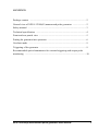
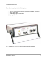
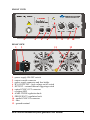
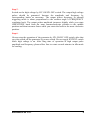
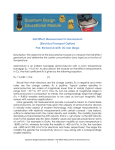
NANOSECOND PULSE GENERATOR
NPG-15/2000(N)
USER MANUAL
© 2013 Megaimpulse Ltd.
Copyright © 2013 MEGAIMPULSE Ltd. All Rights Reserved.
MEGAIMPULSE LTD. PROVIDES THIS MANUAL "AS IS" WITHOUT WARRANTY OF ANY KIND,
EITHER EXPRESS OR IMPLIED, INCLUDING BUT NOT LIMITED TO THE IMPLIED WARRANTIES OR
CONDITIONS OF MERCHANTABILITY OR FITNESS FOR A PARTICULAR PURPOSE. IN NO EVENT
SHALL MEGAIMPULSE LTD., ITS DIRECTORS, OFFICERS, EMPLOYEES OR AGENTS BE LIABLE FOR
ANY INDIRECT, SPECIAL, INCIDENTAL, OR CONSEQUENTIAL DAMAGES (INCLUDING DAMAGES
FOR LOSS OF PROFITS, LOSS OF BUSINESS, LOSS OF USE OR DATA, INTERRUPTION OF BUSINESS
AND THE LIKE), EVEN IF MEGAIMPULSE LTD. HAS BEEN ADVISED OF THE POSSIBILITY OF SUCH
DAMAGES ARISING FROM ANY DEFECT OR ERROR IN THIS MANUAL OR PRODUCT.
SPECIFICATIONS AND INFORMATION CONTAINED IN THIS MANUAL ARE FURNISHED FOR
INFORMATION ONLY, AND ARE SUBJECT TO CHANGE AT ANY TIME WITHOUT NOTICE, AND
SHOULD NOT BE CONSTRUED AS A COMMITMENT BY MEGAIMPULSE LTD. MEGAIMPULSE LTD.
ASSUMES NO RESPONSIBILITY OR LIABILITY FOR ANY ERRORS OR INACCURACIES THAT MAY
APPEAR IN THIS MANUAL, INCLUDING THE PRODUCTS AND SOFTWARE DESCRIBED IN IT.
Products and corporate names appearing in this manual may or may not be registered trademarks or copyrights of
their respective companies, and are used only for identification or explanation and to the owners' benefit, without
intent to infringe.
Megaimpulse Ltd. contact information
Address:
fax:
e-mail:
26 Polytechnicheskaya str., St. Petersburg, 194021 Russia
+7-812-297-3145
[email protected]
CONTENTS
Package content ................................................................................................ 2
General view of NPG-15/2000(N) nanosecond pulse generator ....................... 2
Safety manual ................................................................................................... 3
Technical specification ..................................................................................... 4
Front and rear panels view ................................................................................ 5
Putting the generator into operation .................................................................. 6
Overheat mode .................................................................................................. 9
Triggering of the generator ............................................................................... 9
Recommended optical transmitters for external triggering and output pulse
monitoring ........................................................................................................ 10
NPG-15/2000(N) nanosecond pulse generator user manual
1
PACKAGE CONTENT
Please check the package for the following items:
NPG-15/2000(N) nanosecond pulse generator (hereinafter "generator")
Power supply cable
High voltage output coaxial cable
Two optical cables
User manual
Fig.1. General view of NPG-15/2000(N) nanosecond pulse generator.
MEGAIMPULSE LTD.
2
SAFETY MANUAL
Electrical safety
NPG-15/2000(N) generator is high voltage equipment. Please be very
careful and operate by qualified personnel only.
There is a risk of electric shock, strong electromagnetic interference,
damage of generator or other electronic equipment in case of improper use.
Do not switch on the generator without proper grounding. We recommend
to use grounding cable connected to the terminal at the rear panel of the
generator.
It is strongly prohibited to switch on the generator without output coaxial
cable. There is a risk of electrical arcing on the open coaxial connector and
damage of output circuit of the generator. Please use our special high
voltage coaxial connector and cable only. Standard UHF, N-type or 7/3type connectors are not suitable.
When adding or removing generator to or from the system, ensure that the
power supply ON/OFF switch is switched off and power supply cable is
unplugged before the output cable is connected or disconnected.
Please connect or disconnect any equipment, toggle generator from internal
to external triggering mode or vice versa while generator is in high voltage
OFF state only by HV ON/HV OFF switch.
Operation safety
Please read this manual before installing and using of the generator.
Before using the product, make sure that all cables are applicable and not
damaged. High voltage connectors should be clean and dry, free from dust,
dirt and any obstacles.
To avoid short circuits keep metal parts like clips, screws and staples away
from the generator.
The generator is designed to work in normal laboratory conditions. Avoid
dust, humidity and temperature extremes. Do not place the generator in any
place where it may become wet.
Place the generator on a stable surface.
If you encounter any technical problem with the generator, please contact
with Megaimpulse Ltd. Do not try to repair the generator by yourself.
NPG-15/2000(N) nanosecond pulse generator user manual
3
TECHNICAL SPECIFICATION OF NPG-15/2000
NANOSECOND PULSE GENERATOR
Output pulse voltage
Regulated 13 - 18kV at matched
75 Ohm load, up to 36kV at discharge
reactor
Pulse polarity
positive (NPG-15/2000)
negative (NPG-15/2000N)
Pulse rise time (0.1 – 0.9 Umax)
4 ns
Max pulse energy
30 mJ
Peak pulse power
4.5 MW
Repetition rate
up to 3.2 kHz
Triggering
internal or external
External triggering
optical
Output pulse monitoring
optical
Generator power supply
AC 220-230V 50-60 Hz
Size
248 х 90 х 250 mm3
Weight
4 kg
MEGAIMPULSE LTD.
4
FRONT VIEW
2
4
5
6
7
8
9
10
REAR VIEW
1
3
11
12
1 - power supply ON/OFF switch
2 - output coaxial connector
3 - power supply connector and fuse holder
4 - HV ON/HV OFF - high voltage on/off switch
5 –EXT/INT - external/internal triggering switch
6 - optical SYNC OUT connector
7 - overheat LED
8 - AMPLITUDE regulation knob
9 - FREQUENCY regulation knob
10 - optical SYNC IN connector
11 - fans
12 - ground terminal
NPG-15/2000 nanosecond pulse generator user manual
5
PUTTING THE GENERATOR INTO OPERATION
Please follow strictly the described steps. It helps to prevent damage of the
generator, other equipment, and personnel injury.
Step 1.
Unpack
items:
-
the generator and check the presence into the package of the following
NPG-15/2000(N) generator
power supply cable
output 75 Ohm coaxial cable
two 3 meters length optical cables
Step 2.
Set up the generator. Ground it obligatory by connecting ground cable to terminal
at the rear panel (12).
Step 3.
Check the output coaxial female connector at the front panel of the generator and
co-pair male connector at the cable. Both connectors should be clean and dry, free
from dust, dirt and any obstacles. Clean the connectors by alcohol and/or cotton
bud if necessary.
Attach the cable connector to the generator front panel connector (2). The tight and
firm contact of the connectors is very important for normal operation of the
generator. Even small air gap between the connectors may result in arcing,
destroying of the generator and the cable.
To obtain good and tight contact the following procedure is recommended:
1. Align both connectors.
2. Hold the generator by one hand to prevent moving and press the cable
connector by other hand toward the generator connector.
3. Screw the cable connector nut by hand, usually one or two turns. Do not
rotate the cable connector body.
4. Press the cable connector toward the generator connector again.
5. Once more screw the cable connector nut one or two turns.
6. Repeat steps 4 and 5 up to tight contact. Finally screw the cable connector
nut firmly by hands.
It is recommended to check whether the tight contact obtained or not after the first
test operation of the generator. Unscrew the cable connector; there should be no
any ozone or burnt smell from the cable connector. Please do not connect and
disconnect the high voltage connectors many times to prevent the wearing.
MEGAIMPULSE LTD.
6
Step 4.
Connect the other side of coaxial cable to the load. The cone teflon insulator is
used at the cable end to prevent the discharge between central cable wire and the
cable braid (See Fig.2). You may use additional wires for connection: solder the
high voltage signal wire to the central cable wire and screw/solder ground signal
wire to the ground clamp. It is recommended to use as short additional wires as
possible. More than 10 cm wires result is excessive stray inductance and
significant reducing of the pulse voltage on the load.
Fig.2. The cone teflon insulator at the cable end.
The length of coaxial cable is about 3 meters. Shorter cable may result in damage
of the generator in case of operation on short or open load.
Step 4.
Toggle HV ON/HV OFF switch to HV OFF state.
Toggle EXT/INT switch to INT state.
Place both "amplitude" and "frequency" knobs to the most counterclockwise
position, which corresponds to minimum amplitude and frequency.
Connect power supply cable to power outlet.
Switch on the generator by power switch at the rear panel. The internal fans of the
generator should start to rotate.
NPG-15/2000 nanosecond pulse generator user manual
7
Step 5.
Switch on the high voltage by HV ON/HV OFF switch. The output high voltage
pulses should be generated. Increase the amplitude and frequency by
corresponding knobs as necessary. The output pulses frequency in internal
triggering mode is about proportional to the rotation angle of FREQUENCY
regulation knob. The output pulses amplitude increases slightly while you rotate
AMPLITUDE knob from the most counterclockwise position to the middle
position and then increases faster while you rotate the knob to the most clockwise
position.
Step 6.
Always stop the operation of the generator by HV ON/HV OFF switch, after that
you can switch off the generator by power switch. Do not toggle EXT/INT switch
while high voltage is on. After long time of operation at high output pulse
amplitude and frequency please allow fans to rotate several minutes in idle mode
for cooling.
MEGAIMPULSE LTD.
8
OVERHEAT MODE
NPG-15/2000(N) generator has 75 Ohm impedance coaxial output connector. If
the generator operates on unmatched load with impedance not equal to 75 Ohm
then part of energy inevitably reflects from the load, returns back to generator, and
dissipate in it. About all of generated energy returns back in case of operation on
short or open load. Generator can withstand short or open load, but in case of long
time operation in such regime it may be overheated.
"Overheat" LED lights on in this case and generator stop the operation. Please
switch off high voltage by HV ON/HV OFF switch and allow fans to cool the
generator for a several minutes. "Overheat" LED lights off after the cooling and
generator is ready for operation again.
Unfortunately barrier and other discharge type loads have highly nonlinear nature
and some reflection of energy inevitably occurs. If the generator overheats while it
operates on discharge reactor you can try:
- change the parameters or operation regime of the reactor to increase the part of
energy absorbed in it. To estimate the energy reflected from the load check the
amplitude of the secondary and following pulses by oscilloscope with high
voltage probe connected to the load. You should use 500 MHz or more
bandwidth oscilloscope and 40 kV pulse voltage probe, for example Tektronix
TDS 3052C and Tektronix P6015A probe;
- reduce pulse amplitude and/or frequency.
TRIGGERING OF THE GENERATOR
The generator can operate in three different triggering modes:
Internal triggering
Internal triggering mode is set by switching EXT/INT toggle switch in INT
position. No any additional triggering generator is required for operation in this
regime. Output pulse repetition rate can be adjusted by FREQUENCY regulation
knob at the front panel of the generator.
External triggering
External triggering mode is set by switching EXT/INT toggle switch in EXT
position. External pulse should be applied to optical SYNC IN connector for
generator triggering. Recommended triggering pulse duration is one microsecond.
The delay between triggering pulse front and output pulse (internal generator
delay) is about 300 µs. The maximum allowable pulse repetition rate in this
mode is limited by FREQUENCY regulation knob at the front panel of the
MEGAIMPULSE
NPG-15/2000
nanosecond
LTD.
pulse generator user manual
89
generator, i.e. internal generator frequency sets the upper limit for external
triggering pulses frequency.
Please rotate FREQUENCY regulation knob to the most clockwise position to
allow the maximum external triggering pulses frequency.
The minimum repetition rate is 50 Hz. The lower frequency results in decreasing
of output pulses amplitude.
Burst mode
Burst operation mode can be simply organized by using external pulse generator.
Set EXT/INT toggle switch in EXT position and apply external ENABLE pulse to
optical SYNC IN connector. Output pulse repetition rate is set by FREQUENCY
regulation knob at the front panel of the generator and burst length is determined
by duration of ENABLE pulse.
RECOMENDED OPTICAL TRANSMITTERS FOR
EXTERNAL TRIGGERING AND OUTPUT PULSE MONITORING
NPG-15/2000(N) is equipped by optical connector for external triggering and
output pulse monitoring. AVAGO HFBR-1522Z and HFBR-2522Z transmitters as
well as AVAGO HFBR-4501, HFBR-4511 connectors and HFBR-RUS optical
cable are used for optical signals transmitting.
The recommended external triggering pulse width is 1µs. Maximum frequency is
3.2 kHz and may be limited additionally by FREQUENCY regulation knob. The
optical triggering pulse should be applied to SINC IN connector.
SYNC OUT signal may be used for synchronization and pulse monitoring. This
signal precedes the output high voltage pulse for about 0.5 µs and has 2 µs width.
To use the optical connectors please remove the rubber protective caps by thin
tweezers or other suitable tool, stick gently optical cable with HFBR-4501/HFBR4511 connector into the hole up to click.
Replace the rubber caps back to the holes while you are not using optics to prevent
transmitter lens from the dust.
MEGAIMPULSE LTD.
10