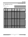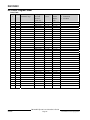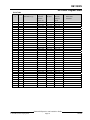
1
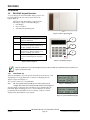
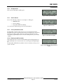
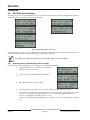
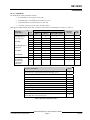
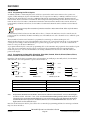
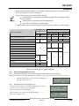
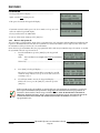
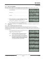
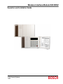
Wireless Interface Module D8125INV
Operation and Installation Guide
D8125INV
D8125INV Operation and Installation Guide
49690E
Page 2
© 2005 Bosch Security Systems
D8125INV
Contents
1.0
Introduction.......................................................................................................................................................................................... 7
1.1
FCC Compliance Notice, Part 15................................................................................................................................... 7
1.2
Other Literature Referenced ............................................................................................................................................ 7
1.3
Documentation Conventions............................................................................................................................................ 7
1.3.1 Type Styles Used in this Manual ..................................................................................................................................... 7
1.3.2 Tips, Important Notes, Cautions and Warnings........................................................................................................... 8
2.0
D8125INV Overview.......................................................................................................................................................................... 9
2.1
Features
................................................................................................................................................................. 9
2.2
Specifications ................................................................................................................................................................. 9
2.2.1 Power..................................................................................................................................................................................... 9
2.2.2 System Supervision......................................................................................................................................................... 10
2.2.2.1 Watchdog.......................................................................................................................................................................... 10
2.2.2.2 Self-Testing ....................................................................................................................................................................... 10
2.3
D8125INV Inovonics Interface Module Point Expansion Description.................................................................. 10
2.4
D8125INV Back View..................................................................................................................................................... 10
3.0
Installation ...........................................................................................................................................................................................11
3.1
Mounting the D8125INV ................................................................................................................................................ 11
3.2
Wiring the D8125INV to the Control Panel and FA400 Receiver ....................................................................... 12
3.2.1 Setting the Jumper for a second receiver................................................................................................................... 13
3.3
D8125INV Quick Startup Recommendations........................................................................................................... 13
3.4
Labeling the Inovonics Transmitters ............................................................................................................................ 13
3.5
D8125INV Keypad Operation....................................................................................................................................... 14
3.5.1 Initial Power-Up ................................................................................................................................................................ 14
3.5.2 RF System OK.................................................................................................................................................................. 15
3.5.3 Call for Service ................................................................................................................................................................. 15
3.5.4 Factory Default Passcode.............................................................................................................................................. 15
3.5.4.1 Entering Invalid Passcodes............................................................................................................................................ 15
3.6
D8125INV Menu Selections ......................................................................................................................................... 16
3.6.1 Beginning steps to add/edit/delete an RF Transmitter ........................................................................................... 16
3.6.1.1 Point Mode ........................................................................................................................................................................ 17
3.6.1.2 Menu 1: Add, Edit or Delete RF Transmitter ............................................................................................................. 18
3.6.1.3 Adding a new RF Transmitter........................................................................................................................................ 18
3.6.1.3 Adding an existing RF Transmitter ............................................................................................................................... 20
3.6.1.4 Deleting an RF Transmitter ............................................................................................................................................ 21
3.6.1.5 Programming the FA570/FA575 Repeater ............................................................................................................... 21
3.6.1.6 Programming the FA113 Keyfob.................................................................................................................................. 22
3.6.1.7 Programming the D9412GV2, D7412GV2, D7212GV2, D9412G, D7412G, D7212G, D9412, D7412,
D7212, and D9112 Control Panels for RF Transmitters ....................................................................................................... 22
3.6.2 Menu 2: Change Installer Passcode ........................................................................................................................... 23
3.6.3 Menu 3: Set System ID .................................................................................................................................................. 24
3.6.4 Menu 4: Clear EEPROM................................................................................................................................................ 25
3.6.5 Menu 5: Set RF System Supervision Interval ............................................................................................................ 25
3.6.6 RF Diagnostics Function ................................................................................................................................................ 26
4.0
Troubleshooting ...............................................................................................................................................................................29
4.1
FA400 Receiver Supervision ........................................................................................................................................ 31
4.2
Missing Transmitters ....................................................................................................................................................... 31
D8125INV Operation and Installation Guide
© 2005 Bosch Security Systems
Page 3
49690E
D8125INV
Contents
4.3
4.4
4.5
4.5.1
4.5.2
4.5.3
4.5.4
4.5.5
4.5.6
4.5.7
4.5.8
4.5.9
4.5.10
5.0
Low Transmitter Battery Conditions.............................................................................................................................31
D8125INV Power Cycle Operation..............................................................................................................................32
Inovonics Frequently Asked Questions .......................................................................................................................32
What's the range of Inovonics Wireless transmitters? ............................................................................................32
What is the range of the Inovonics Wireless repeater? ..........................................................................................32
What does the red decode LED/ light mean? ...........................................................................................................32
Does it matter what way I plug in the programming cable?....................................................................................32
How can I get more range?............................................................................................................................................32
Why can't I program more than 1 transmitter per point? ........................................................................................32
Are your transmitters weatherproof?............................................................................................................................32
What is temperature range for good operation?.......................................................................................................33
Can I externalize an antenna? ........................................................................................................................................33
Does each transmitter need a repeater?.....................................................................................................................33
D8125INV Program Sheet .......................................................................................................................................................... 35
Figures
Table 1: Update Kit Part Numbers ..............................................................................................................................................7
Table 2: Other Literature Referenced ..........................................................................................................................................7
Table 3: D8125INV Specifications...............................................................................................................................................9
Table 4: FA400 Specifications ......................................................................................................................................................9
Figure 1: D8125INV Back View .................................................................................................................................................10
Figure 2: Choosing a Knockout for Wiring Routing (D8103 enclosure shown) ....................................................................11
Figure 3: Mounting the D8125INV base ...................................................................................................................................11
Figure 4: D8125INV to D9412GV2/D9412G/D9412/D9112 Control Panel Wiring Diagram...............................................12
Figure 5: D8125INV to D7412GV2/D7212GV2/7412G/D7212G/D7412/D7212 Control Panel Wiring ..............................13
Figure 6: Tab to expose keypad..................................................................................................................................................14
Figure 7: D8125INV Keypad......................................................................................................................................................14
Table 5: Key Descriptions...........................................................................................................................................................14
Figure 8: Initializing screen ........................................................................................................................................................14
Figure 9: System Defaulted Display ...........................................................................................................................................14
Figure 10: RF System Normal ....................................................................................................................................................15
Figure 11: Call for Service ..........................................................................................................................................................15
Figure 12: Invalid code display ..................................................................................................................................................15
Figure 13: Invalid code, Keypad locked display ........................................................................................................................15
Figure 14: D8125INV Menu Selections .....................................................................................................................................16
Table 6: Recommended Mode Values .......................................................................................................................................17
Figure 15: RF Transmitter status ...............................................................................................................................................18
Figure 16: Connecting cable to D8125INV ...............................................................................................................................20
Figure 17: Connecting cable to transmitter...............................................................................................................................20
Figure 18: Point Number Status ................................................................................................................................................27
Figure 19: RF Point not programmed .......................................................................................................................................27
Figure 20: Call for Service, Enter Code + ENT ........................................................................................................................31
Figure 21: Call for Service, Receiver Missing ............................................................................................................................31
Figure 22: Call for Service, Enter Code + ENT ........................................................................................................................31
Figure 23: Call for Service, Receiver Missing ............................................................................................................................31
D8125INV Operation and Installation Guide
49690E
Page 4
© 2005 Bosch Security Systems
D8125INV
Contents
Tables
Table 1: Update Kit Part Numbers ................................................................................................................................................. 7
Table 2: Other Literature Referenced............................................................................................................................................ 7
Table 3: D8125INV Specifications................................................................................................................................................. 9
Table 4: FA400 Specifications........................................................................................................................................................ 9
Table 5: Key Descriptions.............................................................................................................................................................. 14
Table 6: Recommended Mode Values ....................................................................................................................................... 17
D8125INV Operation and Installation Guide
© 2005 Bosch Security Systems
Page 5
49690E
D8125INV
Notes:
D8125INV Operation and Installation Guide
49690E
Page 6
© 2005 Bosch Security Systems
D8125INV
Introduction
1.0
Introduction
This guide covers the installation of the D8125INV Wireless Interface Module for Inovonics Transmitters. The
D8125INV is an interface module that allows the connection of an Inovonics FA400 Receiver and compatible
transmitters. The D8125INV may be used with the following control panels: D9412G, D7412G, D9412GV2, D7412GV2,
D9412, D9112, D7412, and D7212.
Control Panel Firmware Revision Requirements: The
control panels listed in Table 1 must have firmware version
6.30 or higher. If you need to upgrade the control panel
firmware of a currently installed system, order the
following Update Kits from Bosch Security Systems Order
Processing:
Control Panel
D9412G, D9412
D9112
D7412G, D7412
D7212
D9412GV2
D7412GV2
D7212GV2
Update Kit Part Number
D9499-0650 or higher
D9199-0650 or higher
D7499-0650 or higher
D7299-0650 or higher
All Revs
All Revs
All Revs
Table 1: Update Kit Part Numbers
1.1
FCC Compliance Notice, Part 15
This equipment has been tested and found to comply with the limits for a Class B digital device, pursuant to Part 15 of
the FCC Rules. These limits are designed to provide reasonable protection against harmful interference in a commercial
installation. This equipment generates, uses, and can radiate radio frequency energy, and, if not installed in accordance
with the instructions, may cause harmful interference to radio communications. However, there is no guarantee that
interference will not occur in a particular installation. If this equipment does cause harmful interference to radio or
television reception, which can be determined by turning the equipment on and off, the user is encouraged to try to
correct the interference by one or more of the following measures:
1. Reorient or relocate the receiving antenna.
2. Increase the separation between the equipment and the receiver.
3. Connect the equipment into an outlet on a circuit different from that to which the receiver is connected.
4. Consult the dealer or an experienced radio/TV technician for help.
1.2
Other Literature Referenced
Throughout this manual, references will be made to other documentation. See the following table for the documents
referenced in this manual, which lists the complete part number for ordering purposes.
Name of document
D9412G/D7412G/D9412GV2/D7412GV2 Program Entry Guide
D9412G/D7412G/D9412GV2/D7412GV2 Operation and Installation
Manual
Part Number
47775
43488
Table 2: Other Literature Referenced
1.3
Documentation Conventions
These conventions are intended to call out important features, items, notes, cautions, and warnings that the reader
should be aware of in reading this document.
1.3.1 Type Styles Used in this Manual
To help identify important items in the text, the following type styles are used:
Bold text
Bold Italicized
Italicized text
Courier Text
[CAPITALIZED TEXT]
Usually indicates selections that you may use while programming your control panel. It may also
indicate an important fact that should be noted.
used to denote notes, cautions and/or warnings
Is used to reference the user to another part of this manual or another manual entirely. It is also
used to symbolize names for records that the user will create.
Text that appears like this indicates what may appear on the D5200 Programmer display, keypad,
or internal printer.
Text like this is used to indicate to the user that a specific key should be pressed.
Example: …press the [ESC] key…
D8125INV Operation and Installation Guide
© 2005 Bosch Security Systems
Page 7
49690E
D8125INV
Introduction
1.3.2 Tips, Important Notes, Cautions and Warnings
Throughout this document, helpful tips, important notes, cautions and warnings will be presented for the reader to keep
in mind. These appear different from the rest of the text as follows:
Important Notes - should be heeded for successful operation and programming. Also tips and shortcuts may
be included here.
Caution - These caution the operator that physical damage to the program and/or equipment may occur.
Warning - These warn of the possibility of physical damage to the operator, program and/or equipment.
D8125INV Operation and Installation Guide
49690E
Page 8
© 2005 Bosch Security Systems
D8125INV
Overview
2.0
D8125INV Overview
2.1
Features
2.2
•
Compatible with Bosch Security Systems D9412GV2, D7412GV2, D7212GV2, D9412G, D7412G, D7212G,
D9412, D7412, D7212, and D9112 Control Panels. (FA113 can not be used on the D7212GV2 andD7212G
panels)
•
Menu driven User Interface
•
On the D9412GV2, D9412G, D9412, and D9112, the D8125INV supports up to 2 Inovonics FA400
Receivers (with a maximum of 238 transmitters [119 per bus])
•
On the D7412GV2, D7412G, and D7412, the D8125INV supports up to 2 Invonics FA400 Receivers (with a
maximum of 67 transmitters)
•
On the D7212GV2 and D7212G, the D8125INV supports up to 2 Invonics FA400 Receivers (with up to 32
transmitters in the same location).
•
An unlimited number of FA113 Wireless Keyfobs can be added
•
Used for diagnostic functions to troubleshoot system RF Transmitters
•
Programmable system-wide supervision time interval and individual transmitter check-in time
•
Programmable transmitter configuration (Normally Open/Normally Closed, Internal/External Contact,
EOL Resistor)
Specifications
User Interface:
Operating Voltage:
Current:
Operating Temperature:
Wiring:
Dimensions (HxWxD):
Weight:
LCD Display
Keypad
2 lines by 16 characters, Backlit
0 – 9 numbers
ESC, ENT, PREV, NEXT and DIAG keys
10.2 - 14 VDC supplied by Aux Power from Control Panel or an External
Auxiliary Power Supply.
30 mA typical, 45 mA maximum
plus ≈ 40 mA for each FA400 receiver
+32°F to +149°F (0°C to +65°C), 93% Relative Humidity
18 AWG or 22 AWG Solid or Stranded. Maximum distance from control
panel cannot exceed 5 ft. (1.5 m).
3.94 in. x 6.5 in. x 1.2 in. (10 cm x 16.6 cm x 3 cm)
8.6 oz. (243 g)
Table 3: D8125INV Specifications
Operating Voltage:
Curent:
Wiring:
10.2 VDC to 14 VDC
40 mA Max.
18 AWG or 22 AWG Solid or Stranded. Maximum distance from D8125INV
to FA400 cannot exceed 200 ft. (61 m) or 1000 ft. (305 m) with power supply.
Table 4: FA400 Specifications
2.2.1
Power
If the D8125INV is powered down and then back up, it may take up to a maximum of 5 minutes (up to 15
minutes for 5 minute Transmitter Check-In Time) for all the transmitters to report back to the D8125INV
with their current status. On systems employing fewer transmitters, this time is reduced proportionately.
In addition, when the D8125INV is powered up, all programmed RF points will report Normal until their
state is updated.
The D8125INV power should be connected to the control panel using the Aux Power terminals. If the D8125INV were to
lose power, the following conditions may result:
•
All RF points will report to the control panel as missing (trouble/alarm)
D8125INV Operation and Installation Guide
© 2005 Bosch Security Systems
Page 9
49690E
D8125INV
Overview
•
All RF points will initialize in a normal state when power is reapplied
•
Note:
2.2.2
Alarms initiated prior to power loss would be reset. If the alarm conditions persist when power is restored,
new alarms would be generated.
Programmed settings such as RF point configuration and System ID will remain intact upon the event of a power
loss.
System Supervision
2.2.2.1 Watchdog
The D8125INV implements a watchdog software. Failure of the program will result in a software reset within two
seconds. This may cause a trouble condition on the control panel for the duration of the reset.
2.2.2.2 Self-Testing
The D8125INV EEPROM memory is automatically tested on a periodic basis. The EEPROM checksum is verified every
ten minutes. If the EEPROM checksum fails, a point bus trouble condition will be seen at the control panel.
2.3
D8125INV Inovonics Interface Module Point Expansion Description
Using two D8125INVs, you can program up to 238 (119 per bus) Inovonics Wireless Transmitters to the system on the
D9412GV2, D7412GV2, D9412G, D7412G, D9412, D7412, D7212, and D9112 allow up to 67 Inovonics Wireless
Transmitters, and D7212GV2 and D7212G allow up to 32 Invonics wireless transmitters.
The D8125INV is an integrated interface module and keypad. The keypad is used to access the programming, and
diagnostic functions of the wireless portion of the system. The integrated keypad on the D8125INV is physically different
looking from the typical keypads (D1255, D1256, D1257, and so on) so that it will not be mistaken for a system keypad.
When mounting the D8125INV, it must be within 5 feet (of the control panel. It has been designed such that it should be
mounted right next to the D8103, D8108A or D8109 enclosure.
The D9412GV2, D7412GV2, D7212GV2, D9412G, D7412G, D7212G, D9412, D7412, D7212, and D9112 Control Panels
can have both hardwired (D8128D OctoPOPITS, D8125 Popex / D9127 POPITS, D8125MUX) and wireless points
connected at the same time.
To add wireless points, an Inovonics FA400 Receiver must be connected to the D8125INV which is then connected to the
control panel’s Zonex 1 (and/or Zonex 2) terminals and Aux Power. For best transmitter reception results, the FA400
should be centrally located among the transmitters. If transmitters are at too great of a distance for the FA400 Receiver to
pick up the transmission, an Inovonics RF Repeater may be installed.
2.4
D8125INV Back View
See Figure 1 for areas of importance on the
D8125INV,
1. Programming Jack (Access using
front panel)
2. EPROM Socket – contains
EPROM with encoded software
3. Sounder to indicate valid and
invalid entry via the keypad
4. 4-Wire Zonex Power Panel
Connection Terminal Strip
5. FA-400 Receiver Terminal Strip
6. LCD Contrast Adjustment
The D8125INV provides connection to a
control panel using a Zonex 4-wire interface
and to a FA-400 Receiver via a 3-wire interface.
Figure 1: D8125INV Back View
D8125INV Operation and Installation Guide
49690E
Page 10
© 2005 Bosch Security Systems
D8125INV
Installation
3.0
Installation
The D8125INV is packaged with a Point Label Sheet. Save these, as you will use them when identifying the
point numbers on the Inovonics transmitters.
3.1
Mounting the D8125INV
1.
Select the knockout from the control panel enclosure
that will be used to route the wiring.
2.
Select the location from which the Inovonics FA400
Receiver wiring will be routed.
Wire
Knockouts
Figure 2: Choosing a Knockout for Wiring
Routing (D8103 enclosure shown)
3.
Remove the base of the
D8125INV and use the
screws provided with the unit
to mount it adjacent to the
control panel.
4.
Connect the wiring (see
Section 3.2 Wiring the
D8125INV to the Control
Panel and FA400 Receiver) to
the D8125INV and mount
the cover unit to the base.
D8125INV
Base
Control Panel
Enclosure
Figure 3: Mounting the D8125INV base
D8125INV Operation and Installation Guide
© 2005 Bosch Security Systems
Page 11
49690E
D8125INV
Installation
3.2
Wiring the D8125INV to the Control Panel and FA400 Receiver
The Inovonics FA400 Receiver may be located up to 200 ft. (61 m) from the D8125INV. If the installation requires the
receiver to be mounted farther than this, an external power supply is required. The maximum distance in any case is 1000
ft. (305 m). For optimal mounting instructions, please refer to the instructions supplied by Inovonics.
If an external power supply is used to power the FA400 Receiver, you must:
a) connect the negative terminal wire of the external power supply to the GND terminal of the D8125INV and
the GND terminal of the FA400.
b) if Ground Fault Detect is enabled on the D9412GV2, D9412G, D7412GV2, or D7412G, use a Ground
Isolated Power Supply.
Certain installation configurations may require a second FA400 Receiver (see Section 3.2.1 Setting the Jumper for a second
receiver, p.13.)
Disconnect all power to the Control Panel and to the D8125INV before beginning any work with the internal
components.
Refer to Figure 4 and Figure 5 for the proper wiring connections.
FA400 Receiver
D9412GV2/D9412G/D9412/D9112
Control Communicator Panel
Vs GND OUT
FA400 Receiver
Vs GND OUT
D8125INV
(Points 9-127)
+12v
IN
OUT
GND
+12v
DATA
GND
FA400 Receiver
Vs GND OUT
FA400 Receiver
Vs GND OUT
D8125INV
(Points 129-247)
+12v
IN
OUT
GND
+12v
DATA
GND
Figure 4: D8125INV to D9412GV2/D9412G/D9412/D9112 Control Panel Wiring Diagram
D8125INV Operation and Installation Guide
49690E
Page 12
© 2005 Bosch Security Systems
D8125INV
Installation
FA400 Receiver
D7412GV2/D7212GV2/D7412G/D7212G/D7412/D7212
Control Panel
Vs GND OUT
FA400 Receiver
Vs GND OUT
D8125INV
(Points 9-75)
+12v
IN
OUT
GND
+12v
DATA
GND
To Terminal 3,
AUX Power
To Terminal 9,
Common
Figure 5: D8125INV to D7412GV2/D7212GV2/7412G/D7212G/D7412/D7212 Control Panel Wiring
3.2.1 Setting the Jumper for a second receiver
If the application requires a second FA400 receiver (for example having one receiver on the north side of a large
warehouse and another receiver on the south side of the warehouse), which is typically used for better coverage, follow
the steps below to set up the second FA400 receiver with one D8125INV.
To correctly set the jumper on the FA400 receiver, follow the steps below:
1.
Remove the cover of the FA400 receiver.
2.
Locate the jumper switch located above the reset button.
3.
The FA400 Receiver is shipped
1
2
with the jumper set for 1 receiver.
1
2
1
2
RESET
RESET
4.
Note:
3.3
To set the FA400 Receiver to act as
1
2
a second receiver, position the
jumper to cover the middle and
right pin.
If two receivers are being used and the one receiver goes missing, a ‘Receiver Missing’ message will NOT be
reported since the other receiver is still being seen by the D8125INV, however, the points using it will go missing
after the programmed supervision time.
D8125INV Quick Startup Recommendations
The following information details the recommended programming steps that should be taken when installing a
D8125INV in a new installation.
1. Go to Menu 2 and change the Installer Passcode, if necessary (see Section 3.6.2 Menu 2: Change Installer
Passcode, p.23).
2. Proceed to Menu 1 to begin adding RF Transmitters to the system (see Section 3.6.1.2 Menu 1: Add, Edit or
Delete RF Transmitter, p.18).
3. Use the [DIAG] key for testing the system during and after installation.
3.4
Labeling the Inovonics Transmitters
Prior to programming the Inovonics transmitters or D8125INV, it is recommended that you take the time now to apply
the point number labels from the Point Label Sheet to the individual transmitters.
D8125INV Operation and Installation Guide
© 2005 Bosch Security Systems
Page 13
49690E
D8125INV
Installation
3.5
D8125INV Keypad Operation
To access the keypad on the D8125INV, simply open the door
by gently pulling on the tab on the bottom center of the
keypad (Figure 6).
The keypad of the D8125INV is comprised of the
following (see Figure 7: D8125INV Keypad):
1. LCD Display
2. Keys (see Table 5)
3. Transmitter Programming Jack
Figure 6: Tab to expose keypad
Key
ESC
ENT
PREV
NEXT
DIAG
Description
Escape – Backs out of a programming
option or menu level.
Enter – Accepts a program entry.
Manually scrolls to a previous menu or
point selection. This key will also stop
the auto-scrolling of the menus.
Manually scrolls to the next menu or
point selection. This key will also stop
the auto-scrolling of the menus.
Shortcut to RF Diagnostics menu (see
Section 3.6.6 RF Diagnostics Function,
p.26)
1
2
3
Figure 7: D8125INV Keypad
Table 5: Key Descriptions
Single beep indicates entry is acknowledged, two beeps indicate valid entry and three beep tones indicate an
input error has been made.
3.5.1 Initial Power-Up
When the D8125INV is powered up for the first time from the factory, it will
display Figure 8 for approximately 3 seconds before displaying idle text
(Figure 9, Figure 10 or Figure 11).
The “System”, in this case, is the D8125INV.
Note: The Version 01.01 and System ID of 123 is only used here for an
example. The actual Version and System ID number may be different.
After that, Figure 9 will appear if no transmitters are programmed into the
D8125INV, Figure 10 will appear if one or more transmitters are already
programmed in the D8125INV and are not missing, or Figure 11 will be
displayed if the D8125INV has a system fault.
Figure 8: Initializing screen
Figure 9: System Defaulted Display
D8125INV Operation and Installation Guide
49690E
Page 14
© 2005 Bosch Security Systems
D8125INV
Installation
3.5.2 RF System OK
If the system is OK, Figure 10 will appear.
Figure 10: RF System Normal
3.5.3 Call for Service
If one of the following conditions occurs, Figure 11 will appear.
•
EEPROM Failed
•
Receiver Missing
• Programmed RF Points Missing
see Section 4.0 Troubleshooting, p.29 for more information.
3.5.4 Factory Default Passcode
The D8125INV contains a single passcode. To access the functions in the
D8125INV, this passcode must be entered first. The default passcode loaded at
the factory is 123456 + [ENT]. This passcode may be changed at any time
from within programming mode. To enter the default passcode, press 123456
+ [ENT].
3.5.4.1 Entering Invalid Passcodes
If an invalid passcode is entered, the D8125INV keypad will display Figure 12.
If an invalid passcode is entered 4 times in row, the keypad will display Figure
13.
The D8125INV will disallow any further entries for 5 minutes, unless power is
cycled to the unit.
Figure 11: Call for Service
Figure 12: Invalid code display
Figure 13: Invalid code, Keypad locked
display
D8125INV Operation and Installation Guide
© 2005 Bosch Security Systems
Page 15
49690E
D8125INV
Installation
3.6
D8125INV Menu Selections
After the passcode is entered and the [ENT] key is pressed, the first of the following menus are displayed with each menu
displayed for three seconds before the next one is displayed.
Figure 14: D8125INV Menu Selections
To select a function, press the corresponding number or function key displayed. This menu scrolls for 5 minutes. After 5
minutes the display returns to showing idle text if no keypad activity is detected.
It is highly recommended that a walk test be performed after all programming is completed.
3.6.1 Beginning steps to add/edit/delete an RF Transmitter
Follow the steps below to begin the process of adding a new or existing RF transmitter:
1.
From the Idle Text screen, enter the passcode and press
[ENT] to access the main menu.
2.
Press 1 to add or edit an RF Transmitter (RF Xmtr).
3.
Enter the point number and press [ENT]
4.
At the Transmitter point status screen, do the following depending on the desired action:
To edit mode (see Section 3.6.1.1 Point Mode) and/or check-in time for new transmitters, press 1 and
see Section 3.6.1.3 Adding a new RF Transmitter, p. 18 or to reprogram existing transmitters, see
Section 3.6.1.3 Adding an existing RF Transmitter, p.20.
To delete a transmitter from the D8125INV, press 2 and see Section 3.6.1.4 Deleting an RF Transmitter
p.21.
D8125INV Operation and Installation Guide
49690E
Page 16
© 2005 Bosch Security Systems
D8125INV
Installation
3.6.1.1 Point Mode
The Point Mode setting determines whether:
•
the transmitter is a burg point or fire point,
•
Normally Open or Normally Closed contacts are used,
•
the Internal and/or external contacts are used, and
• end of line resistors are used on the external contacts.
This applies to RF Transmitters that have external contacts and/or internal magnetic contacts (see Table 7).
Inovonics
Transmitter
Mode
FA210 Reduced
Size Universal
FA210W
FA250 High Power
Universal
FA210BN
FA210WBN
FA210W &
FA210WBN
Reduced Size
“Wide-Gap”
Universal
1
2
3
4
6
7
8
9
10
11
5
Normally
Open
External Contact
Normally
End of Line Resistor
Closed
(use 2.2 K ¼ Watt)
Internal
Contact
Fire
Point
12
Inovonics Transmitter
Mode
FA113 Keyfob
(see Section 3.6.1.6 Programming the FA113 Keyfob, p. 22)
FA202 Photoelectric Smoke Detector
FA203S/D Necklace Pendant
FA204 Pendant
FA205S/FA205D Belt Clip/Loop
FA206 ALL
FA207 Glassbreak
FA209 Billtrap
FA216L/H Low Temperature/High Temperature
FA223S/D Single/Double Button Water Resistant Pendant
FA570 High Power Indoor Repeater
FA575 High Power Outdoor Repeater
4
9
4
4
4
2
4
4
4
4
4
Table 6: Recommended Mode Values
D8125INV Operation and Installation Guide
© 2005 Bosch Security Systems
Page 17
49690E
D8125INV
Installation
3.6.1.2 Menu 1: Add, Edit or Delete RF Transmitter
This menu is used to add/edit/delete RF transmitters to the D8125INV and to configure them.
The display for adding, editing or deleting an RF Transmitter is the same.
Figure 15 shows an example of the display.
1. The point address of the RF Transmitter.
2. The mode the RF Transmitter is in (see Section 3.6.1.1 Point
Mode, p.17 for more information).
3. The current check-in selection for that specific RF
Transmitter (see Section 3.6.1.3 Adding a new RF Transmitter,
Figure 15: RF Transmitter status
p.18).
4. This line is used to display the key options for this transmitter (see Section 3.6.1.3 Adding a new RF
Transmitter, p.18).
<command scroll> = “Push 1 to edit” displays for 3 seconds, “2 to delete” displays for 3 seconds, “3 to
program” displays for 3 seconds or “ESC to exit” displays for 3 seconds
Function
Used When…
For more information…
Adding new
Section 3.6.1.3 Adding a new
• adding new transmitter(s)
RF Transmitter, p.18
• programming transmitter(s) and adding to
D8125INV
• to change mode and/or check-in time of
transmitter(s)
Adding existing
Section 3.6.1.3 Adding an
• adding the point to D8125INV without
existing RF Transmitter, p.20
reprogramming the transmitter(s)
• replacing the D8125INV without reprogramming
the transmitter(s)
Deleting
Section 3.6.1.4 Deleting an
• deleting transmitter(s) from the D8125INV
RF Transmitter, p.21
Table 7: RF Transmitter options
3.6.1.3 Adding a new RF Transmitter
To add an RF transmitter, follow the steps below:
Note:
1.
Complete the steps in Section 3.6.1 Beginning steps to add/edit/delete an RF Transmitter, p.16.
2.
After the point number has been entered, the keypad will display:
By default, all new points being added will be assigned Mode 4 and
have a check-in time of 1 minute.
3.
Push [1] to edit the transmitter if the displayed values need to be
modified. If not, proceed to step 8.
4.
The display will change to the following:
D8125INV Operation and Installation Guide
49690E
Page 18
© 2005 Bosch Security Systems
D8125INV
Installation
5.
To set the point mode of the RF Transmitter, see Section 3.6.1.1 Point Mode, p.17 for information on
selectable Point Modes.
6.
After the Mode is selected, the keypad will display the available
check-in time selection of either 1 minute (by pressing [1] +
[ENT]) or 5 minutes (by pressing [2] + [ENT]).
Enter the desired check-in time and press [ENT].
The check-in time is a supervisory signal that is sent from each
transmitter at this interval. Each transmitter shipped from
Inovonics comes defaulted with a 1 minute check-in time. To
extend battery life of the transmitter, this entry may be set to the
5 minute interval. For fire, set the entry to one minute.
7.
After the check-in time is entered, the D8125INV will display the
following.
8.
Push [3] to continue adding the transmitter
9.
The keypad displays two options:
•
Push [1] for a new transmitter
•
Push [2] for an existing transmitter
10.
Press [1] on the keypad
11.
When the keypad displays,
D8125INV Operation and Installation Guide
© 2005 Bosch Security Systems
Page 19
49690E
D8125INV
Installation
a.
Connect the 4-pin end of the programming cable (P/N 50576)
to the programming jack on the D8125INV.
Figure 16: Connecting cable
to D8125INV
b.
Remove the cover of the RF Transmitter.
c.
Connect one end of the programming cable
to the three-pin connector on the
transmitter.
Orientation of the connector to the
transmitter pins is not important.
Figure 17: Connecting cable to transmitter
All transmitters will have the same 3-pin programming header (connector)
12.
Press the reset button on the transmitter.
13.
Once the information is programmed correctly into the
transmitter, the keypad display will show briefly.
If transmitter is not connected to the D8125INV within 5
minutes or the transmitter was unable to accept the information,
a 3-beep error tone will occur and the keypad will display:
Note:
The point number of the transmitter will automatically increment.
14.
Disconnect the programming cable from the transmitter and the D8125INV.
15.
Record the point information on the D8125INV Program Record Sheet (see Section 5.0 D8125INV
Program Sheet, p.35) and on the transmitter point label before proceeding to the next transmitter.
3.6.1.3 Adding an existing RF Transmitter
It may be necessary to take an already installed transmitter and add it again to the D8125INV (especially if the D8125INV
is damaged and needs to be replaced). In this case, the RF transmitters can be added to the D8125INV without having to
manually connect each transmitter to the D8125INV. The Mode and Check-in time are programmed into the
transmitters, not the D8125INV. This option can only be used when replacing a D8125INV.
If changing the mode or check in time or replacing another manufacturer’s interface, program as a new
transmitter.
Refer to the D8125INV Program Record Sheet (see Section 5.0 D8125INV Program Sheet, p.35) for mode and check-in
time when replacing the D8125INV.
D8125INV Operation and Installation Guide
49690E
Page 20
© 2005 Bosch Security Systems
D8125INV
Installation
Do not program any other transmitters for Points 74 and 75 or Points 194 and 195. These are for the FA113
Keyfobs only.
To add an existing RF Transmitter, follow the steps below:
Note:
1.
Complete the steps in Section 3.6.1 Beginning steps to add/edit/delete an RF Transmitter, p.16.
2.
After the point number has been entered, the keypad will display:
3.
Push [3] to continue adding the transmitter
4.
The keypad displays two options:
•
Push [1] for a new transmitter
•
Push [2] for an existing transmitter
5.
Press [2] on the keypad.
6.
The keypad displays the following:
The point number of the transmitter is automatically incremented.
7.
Record the point information on the D8125INV Program Record Sheet (see Section 5.0 D8125INV
Program Sheet, p.35) before proceeding to the next transmitter.
3.6.1.4 Deleting an RF Transmitter
To delete a programmed RF Transmitter, follow the steps below:
Complete the steps in Section 3.6.1 Beginning steps to add/edit/delete an RF Transmitter, p.16.
1.
After the point number has been entered, the keypad display will
2.
display:
Note:
3.
Push [2] to delete the transmitter.
4.
The selected point is deleted and the keypad beeps twice and
displays the following for 3 seconds.
The point number of the transmitter is automatically incremented.
3.6.1.5 Programming the FA570/FA575 Repeater
If it is necessary to install a FA570/FA575 Repeater into this system, it must be programmed as an RF point. However, the
Repeater will only send Low Battery Reports and Tamper Reports. The same procedure for adding an RF Transmitter
(see Section 3.6.1.3 Adding a new RF Transmitter, p.18) is used to add the FA570/FA575 Repeater. The recommended
check-in time interval should be set for 5 minutes.
For further information please refer to the Inovonics FA570 or FA575 Installation Instructions.
D8125INV Operation and Installation Guide
© 2005 Bosch Security Systems
Page 21
49690E
D8125INV
Installation
3.6.1.6 Programming the FA113 Keyfob
An unlimited number of FA113 Keyfobs can be added to a system in the same location. However, the system is not
capable of differentiating the keyfobs. The D8125INV does not supervise Low Battery or Missing conditions for any of
the Keyfobs. The FA113 Keyfob is treated as a Maintained Keyswitch on D9412GV2, D7412GV2, D9412G, D7412G,
D9412, D7412, D7212, and D9112 Control Panels. When using both arming/disarming and alert functions of the keyfob,
Points 74 and 75 (for Zonex Bus 1 on D9412GV2, D7412GV2, D9412G, D7412G, D9412, D7412, D7212, and D9112
Control Panels) and Points 194 and 195 (for Zonex Bus 2 on D9412GV2, D9412G, D9412, and D9112 Control Panels)
are used.
Do not program any other transmitters for Points 74 and 75 or Points 194 and 195. These are for the FA113
Keyfobs only.
The FA113 Keyfob has four buttons: ON, OFF, and two Alert (*) buttons. The ON button is used to arm the area the
point is assigned to and initiate the Master Arm Delay state. The OFF button is used to disarm the area to which the point
is assigned.
The Point Index for Point 74 and 194 must be programmed as a Point Type 4 with a Point Response of 2.
When both Alert buttons are pressed, the D8125INV sends a Short to the control panel for Point 75 or 195. Program the
control panel accordingly so that the Point Response provides the appropriate response. To clear the condition from
Point 75 or 195, press the ON or OFF button.
To program an FA113 keyfob, connect the programming cable to the transmitter and program the lower numbered point
(74 or 194) as a new transmitter and select mode 4. Disconnect the programming cable and program the higher
numbered point (75 or 195) into the D8125INV as an existing transmitter and select mode 4. This will enable both
points on the keyfob.
3.6.1.7 Programming the D9412GV2, D7412GV2, D7212GV2, D9412G, D7412G, D7212G, D9412, D7412,
D7212, and D9112 Control Panels for RF Transmitters
Regardless of the mode that is programmed into each transmitter (Normally Open, Normally Closed), the D8125INV
will send back to the control panel the responses shown in Table 8.
2.2 k
= Normal
2.2 k
= Faulted
2.2 k
= Normal
2.2 k
= Faulted
= Normal
2.2 k
= Tamper
Modes 1 & 8
= Normal
2.2 k
= Faulted
Modes 2 & 9
If the RF Transmitter sends…
a Faulted condition
a Tamper condition
a Normal condition
a Low Battery condition (see note)
= Tamper
Modes 3, 7 & 10
= Faulted
Modes 4, 6 & 11
D8125INV sends to the control panel…
Shorted condition
Open condition
Normal condition
Low Battery condition
Table 8: D8125INV Point Transition Reporting to D9412, D9112, D7412, and D7212 Control Panels
Note:
Only D9412G, D7412G, D7212G, D9412, D7412, D7212, and D9112 Control Panels, Version 6.50 and higher,
are able to send RF BATTERY LOW events. See the D9412G/D7412G Program Entry Guide (P/N: 47775) for
information on programming RF BATTERY LOW events in the Routing section. The D9412GV2, D7412GV2,
and D7212GV2 can use any revision. In addition, RPS Version 3.6 and 9000MAIN Handler Version 1.13 or
higher must be used to enable this event.
Based on the information in Table 8, please follow the recommended programming guidelines for Point Type and Point
Response shown in Table 9.
D8125INV Operation and Installation Guide
49690E
Page 22
© 2005 Bosch Security Systems
D8125INV
Installation
If both a Tamper and Fault condition occur, the Tamper condition takes priority over the Fault condition
and an open condition is sent to the control panel.
Therefore, Bosch Security Systems recommends the following:
•
Controlled points be programmed as ‘Instant alarm on Open’ when armed and ‘Trouble’
when disarmed.
•
24 Hour points be programmed as ‘Instant alarm on Open’
•
Fire points be programmed as ‘Trouble on Open’
An Open condition on the control panel signifies a Tamper while a Short condition is considered a Fault.
Fire
(Fire Point = Yes)
Inovonics Transmitter
Point
Type
Point
Response
n/a
0
1,9
FA113 -- Pt 74 and 194 only
FA113 – Pt 75 and 195 only
FA202
FA203S/D*
FA204*
FA205S/FA205D*
FA206I/S
FA206DS
FA207
FA209*
FA210W
FA210
FA216L/H
FA223S/D
FA250
FA570/FA575
Burg
24 Hour
Point
Point
Type
Response
4
2
0
1,9
Controlled
Point
Point
Type
Response
n/a
1,2,3
0,1,6,7,E
n/a
0
n/a
1,9
n/a
1,2,3
2,3
0,1,6,7,E
0
1,9
0
1,9
1,2,3
n/a
0
1,9
n/a
3
n/a
* = Devices can be programmed as 24 Hour or Controlled Point depending on the application
Table 9: Recommended Point Types/Point Responses
3.6.2 Menu 2: Change Installer Passcode
Note: If the installer’s passcode is lost, you must send the D8125INV to Bosch repair for defaulting.
Shipped from the factory, the D8125INV passcode is 123456. To change this passcode, follow the steps shown below:
1.
From the Main Menu, press [2]. The keypad will display:................
Enter the current passcode.
Note:
Each digit of the passcode will appear as a *.
If the passcode entered does not match the existing passcode, a 3-beep
error tone will occur and the keypad will display:
Then you will return to the Main Menu.
After a valid passcode is entered, the keypad will display: .................
Enter a new 6-digit passcode.
D8125INV Operation and Installation Guide
© 2005 Bosch Security Systems
Page 23
49690E
D8125INV
Installation
The keypad should now display:.........................................................
Again, enter the new 6-digit passcode.
If the passcodes match, the keypad will display:
If a mistake was made and the passcodes do not match, a 3-beep error tone
will occur and the keypad will display:
Then you will return to the Main Menu.
To exit out of this menu, simply press the [ESC] key.
3.6.3 Menu 3: Set System ID
The System ID is a 3-digit number (0-255) that is programmed into each transmitter and D8125INV. In installations that
require two D8125INV Interface Modules, the System ID stored in the D8125INV’s must be different. This ensures that
the transmitters will report back to the correct D8125INV.
From the factory, the D8125INV will come preprogrammed with a random System ID that ranges from 0-255. To modify
the System ID, follow the steps shown below.
1.
From the Main Menu, press the [ENT] key. The keypad will
display:
Note:
123 is used here as an example. The actual System ID may
vary.
followed by: .........................................................................................
2.
Press [ENT]. The keypad displays:......................................................
Enter the new 3-digit System ID. If the System ID does not fall
within the range of 0-255, a 3-beep error tone will occur before
returning to step 1.
3.
If a valid System ID is entered, the keypad will display: ....................
If this is the correct, press the [ENT] key, otherwise press the
[ESC] key.
If the System ID needs to be modified, you must do this prior to programming any transmitters associated to
their respective D8125INV. If the System ID is changed after the transmitters have been programmed, all
transmitters (Point numbers, Mode settings, and Check-in time) WILL BE REPORTED AS MISSING BY
THE D9412, D9412G, D9412GV2, D9112, D7412, D7412G, D7412GV2, D7212, D7212G, AND D7212GV2
CONTROL PANELS ONLY AFTER THE SUPERVISION INTERVAL EXPIRES and will have to be
reprogrammed as new.
D8125INV Operation and Installation Guide
49690E
Page 24
© 2005 Bosch Security Systems
D8125INV
Installation
3.6.4 Menu 4: Clear EEPROM
This menu selection is available if it is believed that the data in the D8125INV is corrupted and you wish to clear the
information and reprogram it. To clear the EEPROM, follow the steps shown below.
To access this menu selection, press 4 from the main menu. The
1.
keypad will display:
followed by:………………………………………………………
and then: ………………………………………………………
2.
Push the [ENT] key. Since clearing the EEPROM will delete the
entire point database and default the D8125INV to the default
settings, another confirmation is required to proceed.
If you wish to exit from this menu, press the [ESC] key. Otherwise, push the [ENT] key one more
time to confirm that you wish to have the EEPROM erased.
The System ID is maintained even after EEPROM is cleared, however, everything else is brought back to factory
default values.
3.
Note:
3.6.5 Menu 5: Set RF System Supervision Interval
The RF System Supervision Interval determines how long the D8125INV will wait to hear at least one check-in
transmission (or any transmission) from a transmitter before sending a Missing condition to the Control Panel. The
interval value that is chosen applies to all transmitters system wide. To set the RF System Supervision Interval, follow the
steps shown below.
1.
To access this menu selection, press 5 from the main menu. The
keypad will then display the following menus:
<value> = None, 4 hr., 12 hr., or 24 hr.
Note:
Note:
All transmitters follow the programmed supervision
interval except the FA113 Keyfob and fire points.
The supervision interval begins when the D8125INV
powers up. If removing a battery in a transmitter to test
this feature, the supervision interval starts before the
transmitter is programmed, taking until the end of the
next supervision window to go into trouble.
D8125INV Operation and Installation Guide
© 2005 Bosch Security Systems
Page 25
49690E
D8125INV
Installation
2.
If [1] + [ENT] is pressed, the keypad will display (for two
seconds before returning to the main menu):
If [2] + [ENT] is pressed, the keypad will display (for two
seconds before returning to the main menu):................................
If [3] + [ENT] is pressed, the keypad will display (for two
seconds before returning to the main menu):................................
If [4] + [ENT] is pressed, the keypad will display (for two
seconds before returning to the main menu):................................
The Supervision Interval for Fire Points (Modes 8 – 12) will remain fixed at 4 hours regardless of
programmed value.
If a receiver does not receive a check-in transmission or any other type of transmission (ex. “Alarm, Tamper”) within the
time programmed, the D8125INV will send a Missing condition for that point to the control panel.
3.6.6
RF Diagnostics Function
The RF Diagnostics function allows you to troubleshoot individual RF transmitters programmed in the system. This
menu is split into two sub-menus: Individual point status and Off-Normal point status.
To access the RF Diagnostics menu, follow the steps shown below.
1.
To access this function, one of two methods can be used.
a.
Press [DIAG] on the keypad from idle text.
Enter a valid passcode and press [ENT]:
b.
From the main menu (after a valid passcode has been
entered), press [DIAG] on the keypad.
D8125INV Operation and Installation Guide
49690E
Page 26
© 2005 Bosch Security Systems
D8125INV
Installation
2.
The keypad will then display the following menus (if there are
no system faults on the D8125INV):
See step 4 below
See step 5 below
3.
If [1] is pressed, this menu allows you to jump to any RF point
programmed into the D8125INV. If [1] is pressed from this
menu, the keypad will display:
4.
After a valid RF Point Number is entered, Figure 18 will be displayed.
Figure 18: Point Number Status
Item
1
Variable
xxx
2
<value>
Description
?
D8125INV has not received
at least 30 transmissions to
determine signal strength
Bad Transmitter must be
relocated
OK Good signal strength
Normal
Faulted
Tamper
Missing
Low Bat
Tamper, Low Bat
Faulted, Low Bat
Table 10: Variable Descriptions
If an invalid RF Point Number is entered, the following is
displayed:
If the D8125INV is connected to Zonex 1, enter point numbers
9-127 (or 9-75 if D7412G, D7412, D7412GV2, D7212, D7212G,
or D7212GV2 ).
Figure 19: RF Point not
programmed
Points 74 and 75 and Points 194 and 195 are reserved for the FA113 Keyfob.
If the D8125INV is connected to Zonex 2, enter point numbers 129-247. After entering the point
number and pressing the [ENT] key, the keypad will display Figure 18.
D8125INV Operation and Installation Guide
© 2005 Bosch Security Systems
Page 27
49690E
D8125INV
Installation
To view the next RF point number programmed in the D8125INV, press [NEXT], otherwise press
[PREV] to see the previously programmed RF point.
5.
If [2] is pressed from this menu, the keypad will display all off-normal points at a 2-3 second scroll
rate. By pressing [NEXT] or [PREV] while this is scrolling stops the auto scroll. The [NEXT] and
[PREV] keys are used to view point status individually. (See Figure 18)
6.
The keypad will then revert back to the initial Diagnostics menu:
See step 4
See step 5
D8125INV Operation and Installation Guide
49690E
Page 28
© 2005 Bosch Security Systems
D8125INV
Troubleshooting
4.0
Troubleshooting
Symptom
Diagnosis
D8125INV has lost
communications with the FA400
receiver. This will cause all
programmed RF points on that
D8125INV to go missing
immediately (missing alarms or
missing troubles at control panel.)
It will also cause a Point Bus Fail 1
(or 2) at the control panel.
The D8125INV hasn't 'heard' from
an RF point for the length of the
programmed supervision interval.
The most common reasons are
damage to the transmitter, physical
environmental changes, or a dead
battery.
To find out which RF points are
missing, press [DIAG] for RF
diagnostics, then [2] for Offnormal point’s status. Display will
start at lowest numbered offnormal point and automatically
scroll up. [NEXT] or [PREV] keys
will switch to manual scrolling.
Internal diagnostics checksum
failure
Undesired point response at
D8125INV (e.g. RF point is normal
when it should be faulted, etc.)
Note: When testing RF points,
first check for proper point
response at D8125INV RF
diagnostics. When point
responses are correct at the
D8125INV, then move on
to testing point responses
at the control panel.
Programmed mode of transmitter
is incorrect.
Wiring of external circuit is
incorrect.
Remedy
Check for LED activity at
receiver(s).
Double-check wiring between
D8125INV and FA400.
•
+12 V/Vs to GND = approx.
13 VDC
•
DATA/OUT to GND =
fluctuating voltage (data
flowing)
Make sure that jumper on FA400 is
set to '1' if one FA400 is used on a
D8125INV; If two FA400's are used
on a D8125INV, set the jumper on
one FA400 receiver to '1', and the
jumper on the FA400 receiver to
'2'.
Locate missing transmitter.
Check for physical damage. Check
battery voltage, which should equal
3.0 VDC min. Bring transmitter
closer to receiver and cause a
transmission, to determine if a
range problem exists due to a
change in the environment. For
range problems, a 2nd FA400 per
D8125INV, or an FA570/575
repeater may be used.
Clear EEPROM, and reprogram
the D8125INV and all of its
transmitters. If EEPROM failure
re-occurs, return the D8125INV
for repair/replacement.
Check the mode charts in Table 9:
Recommended Point Types/Point
Responses, p.23. Make sure mode
selection is correct for that
transmitter model. For Universal
transmitters, make sure the mode
selection is correct for the external
circuit type (NO/NC/EOL?/not
used), and whether or not the
internal contact (magnet) is used.
Correct wiring of external circuit
D8125INV Operation and Installation Guide
© 2005 Bosch Security Systems
Page 29
49690E
D8125INV
Troubleshooting
Symptom
Point response is correct at the
D8125INV, but incorrect at the
control panel (for example, RF
point is in trouble when it should
be faulted, etc.).
Diagnosis
Point programming at control
panel is incorrect.
RF points change state
unexpectedly, with no actual state
change at transmitter
Two or more transmitters are
programmed as the same RF point
number.
There is another, nearby
D8125INV system with
transmitters, programmed with the
same System ID.
Received signal level for that point
is low.
in RF Diagnostics
in RF Diagnostics
D8125INV has not received
enough recent transmissions from
that RF point to give an 'OK' or
'BAD' signal indication; Several
transmissions are required. The
signal indication will start out as '?'
after power up, after programming
an RF point, or after an RF point
has gone missing.
Remedy
Make sure point programming at
control panel is correct, especially
the Point Response Type.
Remember that regardless of
transmitter type or configuration
of an external circuit, the
D8125INV will always report a
fault to the control panel as a short,
and a tamper as an open. In most
cases, a point response type that
gives trouble on open is desired.
Transmitters send RF point status
(fault/tamper/normal) at status
change and at 1 min. or 5 min.
check-in intervals. If two duplicate
points are in different states, the RF
point state at the D8125INV may
keep changing as the check-in
transmissions from each
transmitter are received. If
duplicate RF points are in the same
state, RF point state at the
D8125INV will stay the same.
The system ID is shipped at a
random value of 000-255.
D8125INV systems that are within
RF range of each other must have
different System ID's, to avoid
interaction of the systems. That's
why it's a good idea to check for
duplicate System ID's if two
D8125INVs are used. Remember
that if the System ID is changed, all
transmitters in that D8125INV
system will have to be
reprogrammed as new.
A second FA400/receiver can be
added to a D8125INV and
mounted in a different location to
increase range An Inovonics
FA570/575 high-power repeater
may be used to increase range to a
greater degree.
Cause several transmissions to
update signal level. About 4 alarms
or tampers and 4 restorals spaced 5
seconds apart will cause enough
transmissions to get an accurate
signal indication. Without
activations, it will take about a
half-hour to get signal strength
readings if transmitter Check-In
time is set to 1 minute. It will take
about 2 hours if Check-In time is
set to 5 minutes.
D8125INV Operation and Installation Guide
49690E
Page 30
© 2005 Bosch Security Systems
D8125INV
Troubleshooting
Symptom
RF Keyfob transmitter points go
missing
RF points go missing when
programmed supervision interval
= none.
Diagnosis
RF keyfobs may only be
programmed as points 74 & 75, or
as points 194 & 195. Since keyfobs
can be carried off-site, these points
are not supervised, regardless of
the programmed RF supervision
interval.
These RF Points are programmed
as Fire Points (transmitter modes
8-12). Transmitters programmed
as Fire points will be supervised at
4 hour intervals, regardless of
programmed supervision interval
time.
Remedy
Reprogram RF keyfob transmitters
as Points 74 & 75 (zonex 1), or
Points 194 & 195 (zonex 2).
If those RF points are not for Fire
devices, connect and reprogram
the transmitter as new, changing
the transmitter Mode to non-fire
(Modes 1-7).
Table 11: Troubleshooting Solutions
4.1
FA400 Receiver Supervision
The D8125INV supervises the Inovonics FA400 receiver by periodically polling it.
If the FA400 does not respond to the polls over a five minute period, the
D8125INV will initiate a Point Bus Trouble event back to the control panel. The
control panel will then initiate a Point Bus Fail 1 (or 2) event.
If this occurs, the D8125INV will display Figure 20.
Figure 20: Call for Service,
Enter Code + ENT
Enter a valid passcode and then Figure 21 will be displayed.
Figure 21: Call for Service, Receiver
Missing
4.2
Missing Transmitters
A transmitter may go missing in the system due to the following most common
reasons:
•
dead battery
•
physical environmental changes
Figure 22: Call for Service,
Enter Code + ENT
• damage to the transmitter
The D8125INV will display Figure 22.
Enter a valid passcode and then Figure 23 will be displayed.
Note: The number 019 (which is used as an example) refers to the actual
quantity of points missing, not the specific point number.
Figure 23: Call for Service, Receiver
Missing
4.3
Low Transmitter Battery Conditions
When the transmitter reports low battery conditions and replacement is necessary be sure to press reset button on
transmitter after replacing battery. Also, be sure to test the transmitter for proper operation after replacing battery.
D8125INV Operation and Installation Guide
© 2005 Bosch Security Systems
Page 31
49690E
D8125INV
Troubleshooting
4.4
D8125INV Power Cycle Operation
If the D8125INV is powered down and then back up, it may take up to a maximum of 5 minutes for all the transmitters
to report back to the D8125INV with their current status. On systems employing fewer transmitters, this time is reduced
proportionately.
In addition, when the D8125INV is powered up, all transmitters report Normal until their state is updated.
4.5
Inovonics Frequently Asked Questions
This FAQ is reprinted with permission from Inovonics.
4.5.1
What's the range of Inovonics Wireless transmitters?
Range for any wireless device depends very heavily on the environment. In general, radio signals will be absorbed into
materials that contain moisture, such as concrete, water, and earth. Radio signals will bounce off of metal surfaces and
penetrate fairly easily through drywall or glass. In any case, the radio signals will lose some power as they pass through or
come in contact with objects. For comparison purposes the only equitable measurement is "true-line-of-sight". This is a
condition where there are absolutely no obstacles between the transmitter's antenna and the receiver's antenna.
At this writing, there are 2 types of output power used on Inovonics Wireless transmitters.
1. High Power. The line of sight range is 10,000 ft. Available only in the FA250 and FA570/575.
2. Standard Power. The line of sight range is 2,500 ft. Available in all transmitters except the FA250.
The FA250 will program the same as the FA210W.
It is rare that an installation has a true-line-of-sight condition so for a more definitive answer on range we suggest you
test the environment with an FA715 Survey Kit.
In a typical building environment our 900 MHz signal propagates easily around the metal studs and concrete floors.
Customers regularly tell us that they are impressed with the performance. If additional coverage is needed we offer an
FA570/575 Intelligent Repeater. These repeaters support an unlimited number of Inovonics Wireless transmitters.
4.5.2
What is the range of the Inovonics Wireless repeater?
The repeater uses our High Power specification in its output. The re-transmit range is 10,000 ft. line of site.
The receive coverage area is dependent on the power output of the transmitters it repeats.
4.5.3
What does the red decode LED/ light mean?
This LED is located on the circuit board of Inovonics Wireless receivers. It is an indicator of the RF noise in the area.
Every time the light blinks the receiver is attempting to decode a signal. This light shows that the unit is turned on and
working. It is listening to all of the radio energy in the environment to determine if any signals are coming in on the
Frequency Agile protocol. If a valid FA signal is received, the adjacent Valid LED will illuminate.
4.5.4
Does it matter what way I plug in the programming cable?
NO - As long as the 3 pins are inserted into the programming cable, polarity isn't important.
4.5.5
How can I get more range?
You can use Inovonics FA570/FA575 Repeaters to extend the range of any Inovonics Wireless system.
4.5.6
Why can't I program more than 1 transmitter per point?
Programming more than a single transmitter to a given point number defeats the ability of the Inovonics Wireless system
to supervise itself. This is a practice called "stacking points" and is discouraged in practice. Never stack points in a lifesafety or security application.
4.5.7
Are your transmitters weatherproof?
Our FA223S pendant transmitter is water-tight to a depth of 1 foot. In addition, we offer the ACC640 NEMA Enclosure
for outdoor environments. Many installers simply seal our transmitters in PVC pipe when used in outdoor
D8125INV Operation and Installation Guide
49690E
Page 32
© 2005 Bosch Security Systems
D8125INV
Troubleshooting
environments. Your choice of enclosures will depend on your specific needs. Be sure you keep in mind maintenance
needs including battery replacement in a few years!
4.5.8
What is temperature range for good operation?
+40°F to +135°F (+4.4°C to +57.2°C)
4.5.9
Can I externalize an antenna?
No. Our FA575 repeater is our external antenna.
4.5.10 Does each transmitter need a repeater?
No. Each repeater can re-transmit multiple transmitters from multiple systems and do not require programming for
individual points.
D8125INV Operation and Installation Guide
© 2005 Bosch Security Systems
Page 33
49690E
D8125INV
Troubleshooting
Notes:
D8125INV Operation and Installation Guide
49690E
Page 34
© 2005 Bosch Security Systems
D8125INV
D8125INV Program Sheet
5.0
D8125INV Program Sheet
Installer Passcode (123456)
System ID
Supervision Interval (4 hours)
Point Table
Point
#
Mode
Inovonics
Transmitter Type
Loop Type
(External
Contact)
(circle one)
N/O or N/C
N/O or N/C
N/O or N/C
N/O or N/C
N/O or N/C
N/O or N/C
N/O or N/C
N/O or N/C
N/O or N/C
N/O or N/C
N/O or N/C
N/O or N/C
N/O or N/C
N/O or N/C
N/O or N/C
N/O or N/C
N/O or N/C
N/O or N/C
N/O or N/C
N/O or N/C
N/O or N/C
N/O or N/C
N/O or N/C
N/O or N/C
N/O or N/C
N/O or N/C
N/O or N/C
N/O or N/C
N/O or N/C
EOL
Resistor?
Yes
Yes
Yes
Yes
Yes
Yes
Yes
Yes
Yes
Yes
Yes
Yes
Yes
Yes
Yes
Yes
Yes
Yes
Yes
Yes
Yes
Yes
Yes
Yes
Yes
Yes
Yes
Yes
Yes
/
/
/
/
/
/
/
/
/
/
/
/
/
/
/
/
/
/
/
/
/
/
/
/
/
/
/
/
/
No
No
No
No
No
No
No
No
No
No
No
No
No
No
No
No
No
No
No
No
No
No
No
No
No
No
No
No
No
Internal
Contacts
(Magnetic)
Used?
Yes / No
Yes / No
Yes / No
Yes / No
Yes / No
Yes / No
Yes / No
Yes / No
Yes / No
Yes / No
Yes / No
Yes / No
Yes / No
Yes / No
Yes / No
Yes / No
Yes / No
Yes / No
Yes / No
Yes / No
Yes / No
Yes / No
Yes / No
Yes / No
Yes / No
Yes / No
Yes / No
Yes / No
Yes / No
Notes:
•
•
Point Text
Location
D8125INV Operation and Installation Guide
© 2005 Bosch Security Systems
Page 35
49690E
D8125INV
D8125INV Program Sheet
Point Table
Point
#
Mode
Inovonics
Transmitter Type
Loop Type
(External
Contact)
(circle one)
N/O or N/C
N/O or N/C
N/O or N/C
N/O or N/C
N/O or N/C
N/O or N/C
N/O or N/C
N/O or N/C
N/O or N/C
N/O or N/C
N/O or N/C
N/O or N/C
N/O or N/C
N/O or N/C
N/O or N/C
N/O or N/C
N/O or N/C
N/O or N/C
N/O or N/C
N/O or N/C
N/O or N/C
N/O or N/C
N/O or N/C
N/O or N/C
N/O or N/C
N/O or N/C
N/O or N/C
N/O or N/C
N/O or N/C
N/O or N/C
N/O or N/C
N/O or N/C
N/O or N/C
EOL
Resistor?
N/O or N/C
Yes / No
Yes
Yes
Yes
Yes
Yes
Yes
Yes
Yes
Yes
Yes
Yes
Yes
Yes
Yes
Yes
Yes
Yes
Yes
Yes
Yes
Yes
Yes
Yes
Yes
Yes
Yes
Yes
Yes
Yes
Yes
Yes
Yes
Yes
/
/
/
/
/
/
/
/
/
/
/
/
/
/
/
/
/
/
/
/
/
/
/
/
/
/
/
/
/
/
/
/
/
No
No
No
No
No
No
No
No
No
No
No
No
No
No
No
No
No
No
No
No
No
No
No
No
No
No
No
No
No
No
No
No
No
Internal
Contacts
(Magnet)
Used?
Yes / No
Yes / No
Yes / No
Yes / No
Yes / No
Yes / No
Yes / No
Yes / No
Yes / No
Yes / No
Yes / No
Yes / No
Yes / No
Yes / No
Yes / No
Yes / No
Yes / No
Yes / No
Yes / No
Yes / No
Yes / No
Yes / No
Yes / No
Yes / No
Yes / No
Yes / No
Yes / No
Yes / No
Yes / No
Yes / No
Yes / No
Yes / No
Yes / No
Notes:
•
•
Point Text
Location
Yes / No
D8125INV Operation and Installation Guide
49690E
Page 36
© 2004 Bosch Security Systems
D8125INV
D8125INV Program Sheet
Point Table
Point
#
Mode
Inovonics
Transmitter Type
Loop Type
(External
Contact)
(circle one)
N/O or N/C
N/O or N/C
N/O or N/C
N/O or N/C
N/O or N/C
N/O or N/C
N/O or N/C
N/O or N/C
N/O or N/C
N/O or N/C
N/O or N/C
N/O or N/C
N/O or N/C
N/O or N/C
N/O or N/C
N/O or N/C
N/O or N/C
N/O or N/C
N/O or N/C
N/O or N/C
N/O or N/C
N/O or N/C
N/O or N/C
N/O or N/C
N/O or N/C
N/O or N/C
N/O or N/C
N/O or N/C
N/O or N/C
N/O or N/C
N/O or N/C
N/O or N/C
N/O or N/C
N/O or N/C
EOL
Resistor?
Yes
Yes
Yes
Yes
Yes
Yes
Yes
Yes
Yes
Yes
Yes
Yes
Yes
Yes
Yes
Yes
Yes
Yes
Yes
Yes
Yes
Yes
Yes
Yes
Yes
Yes
Yes
Yes
Yes
Yes
Yes
Yes
Yes
Yes
/
/
/
/
/
/
/
/
/
/
/
/
/
/
/
/
/
/
/
/
/
/
/
/
/
/
/
/
/
/
/
/
/
/
No
No
No
No
No
No
No
No
No
No
No
No
No
No
No
No
No
No
No
No
No
No
No
No
No
No
No
No
No
No
No
No
No
No
Internal
Contacts
(Magnet)
Used?
Yes / No
Yes / No
Yes / No
Yes / No
Yes / No
Yes / No
Yes / No
Yes / No
Yes / No
Yes / No
Yes / No
Yes / No
Yes / No
Yes / No
Yes / No
Yes / No
Yes / No
Yes / No
Yes / No
Yes / No
Yes / No
Yes / No
Yes / No
Yes / No
Yes / No
Yes / No
Yes / No
Yes / No
Yes / No
Yes / No
Yes / No
Yes / No
Yes / No
Yes / No
Notes:
•
•
Point Text
Location
D8125INV Operation and Installation Guide
© 2005 Bosch Security Systems
Page 37
49690E
D8125INV
D8125INV Program Sheet
Notes:
D8125INV Operation and Installation Guide
49690E
Page 38
© 2004 Bosch Security Systems
D8125INV
D8125INV Program Sheet
Notes:
D8125INV Operation and Installation Guide
© 2005 Bosch Security Systems
Page 39
49690E
© 2005 Bosch Security Systems
130 Perinton Parkway, Fairport, NY 14450-9199 USA
Customer Service: (800) 289-0096; Technical Support: (888) 886-6189
49690E
Operation and
Installation Guide
6/05
D8125INV
Page 40 of 40