1
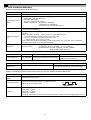
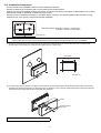
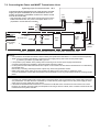
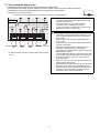
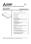
GB
Mitsubishi Electric Air Conditioner Network System
PI controller
PAC-YG60MCA
Installation/Instruction Manual
Table of Contents
Page
1.
2.
3.
4.
5.
6.
7.
8.
9.
10.
11.
12.
Safety Precautions ..............................................1
Usage ..................................................................2
Parts List..............................................................2
Specifications ......................................................2
4-1.
Device Specifications .........................2
4-2.
External Dimensions...........................3
Example of System Configuration .......................4
Installation ...........................................................5
6-1.
Parts Purchased Separately...............5
6-2.
Installation Instructions .......................6
Wiring Instructions ...............................................7
7-1.
Terminal Diagram ...............................7
7-2.
Connecting the Power and M-NET
Transmission Lines.............................8
7-3.
Connecting the Signal Lines...............9
(1) Pulse input (non-voltage a-contact)....9
Initial Settings ....................................................10
Dip Switch Functions .........................................11
LED Display Designations .................................12
10-1.
Pulse Input and Error Displays .........12
10-2.
Communication Error Displays .........12
System Operation Test......................................13
Precautions for Expansion.................................13
Before using the device carefully read this installation/instruction manual to ensure proper operation.
Keep this manual for future reference and give it to the technician when the device is reinstalled or repaired.
1 Safety Precautions
• Thoroughly read the following safety precautions before use.
• Hazards that can occur from incorrect handling are classified by the symbols below:
Warning
Incorrect handling can result in death, serious injury, etc.
Caution
Incorrect handling can result in bodily injury and/or structure damage.
• After reading this manual, keep this manual for future reference. When the device is reinstalled or repaired, give this
manual to those who provide these services. When the user changes, make sure that the new user receives this
manual.
WARNING
Only a dealer or qualified technician should install, relocate,
reinstall, or repair the device.
Improper installation or repair may result in electrical shock or fire.
Do not make any modifications or alternations to the device.
Modifications or improper repair may result in electric shock or fire.
Consult your dealer for repair.
Properly install the device on a stable, load-bearing surface.
Device installed on an unstable surface may fall and cause injury.
All electrical work should be performed by an authorized
electrician according to local regulations and instructions
outlined in this manual.
Capacity shortage to the power supply circuit or improper installation
may result in electrical shock or fire.
Only use the specified cables; securely connect each so that the
terminals do not bear any cable weight.
Improperly connected or short-circuited cables may produce heat and
cause a fire.
Properly install the device according to the instructions in this
Installation/Instruction Manual.
Improper installation may result in electric shock or fire.
CAUTION
Do not install the device in a location where a flammable gas leak
may occur.
Gas may leak, collect around the device, ignite, and/or explode.
Do not install the device in a bathroom, kitchen, or any room
where steam could form. Condensation may develop and cause
electrical shock and/or the device to malfunction.
Do not install the device in environments where large amounts of
oil (including machine), sulfidizing gas, or acidic, alkaline,
chemical sprays are present.
These types of substances may damage internal parts, cause device
performance to be reduced, and cause electrical shock.
Use standard wires with the proper current capacity to avoid the
possibility of current leak, excessive heat, and/or fire.
Do not touch the main circuit board; also, make sure that dust
does not accumulate on the circuit board.
When installing the device in a hospital, communication facilities, etc., provide sufficient protection against frequency noise.
Power generators and inverters, high-frequency medical, or radio communication equipment may interfere with the normal operation of this device.
Subsequently, the device may also affect medical treatment, image broadcasting, etc., by creating frequency noise.
Include some slack in the power supply wires.
Tension on the wires may cause them to excessively heat up and/or
break, resulting in a fire.
Do not immerse the device in water.
Doing so may lead to electric shock or malfunctions.
The maximum applied voltage for the device is 24 VDC - do not
use with an AC power source. (The maximum applied voltage for
the M-NET terminal is 30 VDC.)
Using the incorrect voltage may result in device failure, ignition, and/
or fire.
Do not install the device in a location where there is direct
sunlight or where the temperature may become greater than 40°C
(104°F) or less than 0°C (32°F).
If the device is installed in such place, it may result in deformation or
malfunctions.
1
2 Usage
The PI controller counts pulses from a power meter, gas meter, water meter, and calorimeter. Combining the use of the
G(B)-50A and TG-2000A allows for calculating the charges for each unit and performing peak-cut (e.g., demand control)
operation.
Caution: Usage Restrictions
• Mitsubishi Electric does not take financial responsibility for damages caused by issues beyond our control or special
circumstances (predicable or unpredictable); and secondary or accidental damages, and damages to other objects. We also
do not take financial responsibility for opportunities lost as a result of device failure, or electrical power failure at the enduser site.
Mitsubishi Electric does not take financial responsibility caused by end-users' requests including, but not limited to, device
testing, startup, readjustment, and replacement.
• Because the PI controller only counts pulses, accuracy and performance of pulse conversion depend on the meter.
Mitsubishi Electric does not take financial responsibility for damages caused by issues beyond our control or special
circumstances (predicable or unpredictable); and secondary or accidental damages and damages to other object.
• Depending on each country's laws and regulations, etc., there may be cases these measured charges cannot be used for
certificate of transaction.
3 Parts List
• The following parts should be included in your shipment:
Number
Part Name
Quantity
1
PI controller
1
2
Installation/instruction manual (this document)
1
* In addition to the parts listed above, see your local Mitsubishi Electric dealer to purchase the other parts necessary to operate this device (Refer to
section 6-1). Furthermore, depending on the application, other Mitsubishi Electric parts may be required.
For details, refer to "6. Installation".
4 Specifications
4-1. Device Specifications
Item
Power Supply
Rating and Specification
24 VDC±10%: 5 W
Screw terminal block (M3) (*3)
Screw terminal block (M3) (*3)
M-NET communication 17 to 30 VDC (*1)
Number of contacts: 4
Pulse signal: a-contact
Pulse width: 100 ms to 300 ms
(Idle period until next pulse: 100 ms or more)
Interface
Non-voltage a-contact
input
100 ms or more
Screwless terminal block
100 ms ~ 300 ms
Rated voltage: 24 VDC
Rated current: 1 mA or less (*2)
Environment
Conditions
Temperature
Humidity
Operating temperature range
0 to 40°C [32°F to 104°F]
Storage temperature range
-20 to 60°C [-4°F to 140°F]
*Refer to section 6-1.
30 to 90%RH (no condensation)
Dimensions
200 (W) × 120 (H) × 45 (D) mm / 77/8 (W) × 43/4 (H) × 125/32 (D) in
Weight
0.6 kg / 13/8 lb
Time Backup
During Power
Failure
In the event of power failure or shut-off, the internal capacitor will continue to track time for approximately one week.
(The internal capacitor takes about 24 hours to fully charge; a replacement battery is not necessary.)
Installation
Environment
Inside a control panel (indoors)
* Use this product in a hotel, a business office environment or similar environment.
*1: Supply electric power from a power unit for the transmission line or an outdoor unit. Furthermore, the power consumption factor of the M-NET
circuitry of this device is "1/4" (equivalent to one ME Remote Controller).
*2: Supply electric power from the main unit to the contacts of the meters.
*3: M3 is the size of the screw on the terminal block (ISO metric screw thread). The number indicates the screw diameter (mm).
2
4-2. External Dimensions
52 (21/16)
200 (77/8)
150 (529/32)
46.5 (127/32)
45 (125/32)
4.5
9 (3/8)
110 (411/32)
120 (43/4)
107.6 (41/4)
(3/16)
This device complies with Part15 of the FCC Rules.Operation is
subject to the following two conditions: (1)this device may not cause
harmful interference, and (2)this device must accept any interference
received, including interference that may cause undesired operation.
[ 24 VDC Power Supply]
27 (13/32)
26 (11/32)
83.5 (35/16)
15 (19/32)
26 (11/32)
3
Unit: mm (in)
5 Example of System Configuration
<Restrictions>
Maximum of 5 units (total of 20 channels) per G(B)-50A
Power supply unit
PAC-SC50KUA
Centralized control line
M-NET
G-50A or GB-50A
LAN
However, the number of units that can be connected to a
G(B)-50A is up to 50 including this device, an indoor unit,
LOSSNAY unit, etc.
* For the number of units that can be connected when controlling
this device with TG-2000A, refer to the instruction manual for
TG-2000A.
TB7
Indoor control line
M-NET
TB3
PI controller
CITY MULTI
G(B)-50A Web
or TG-2000A
24 VDC
power supply
PI controller
Watt-hour meter with
pulse transmitter, etc.
24 VDC
power supply
Uninterruptible
power supply
(UPS)
Up to 4 contacts
Watt-hour meter with
pulse transmitter, etc.
Uninterruptible
power supply
(UPS)
Up to 4 contacts
* This figure omits the power supply line and only shows the transmission line.
Note:
• For the shield ground of the M-NET centralized control line for central control, use single-point grounding at the power unit
for the transmission line.
However, when supplying electric power to the M-NET centralized control line from the R410A series outdoor unit without
using a power supply unit for the transmission line, use single-point grounding at the TB7 of that outdoor unit.
Furthermore, when connecting this device to the M-NET indoor control line, use grounding at the TB3 for each outdoor unit
system.
• Connecting an Uninterruptible power supply (UPS) to the 24 VDC power supply is recommended in order to prevent the loss
of pulse data in the event of a power failure.
If a UPS cannot be connected, try to make the AC power supply to the 24 VDC power supply as much same as the AC power
supply line to the meters.
• This device does not support level meters. To use a level meter, incorporate a Converter circuit externally and convert to
pulse input.
• If the M-NET transmission line of this device is connected to an M-NET indoor control line and the outdoor unit is down
because, for example, the power supply is interrupted for servicing or there is a failure, the PI controller cannot be controlled
from the system controller.
4
6 Installation
6-1. Parts Purchased Separately
Prepare the following parts to install this device.
Required Part
Specification
Unit fixing screws
M4 screw × 4 (* M4: ISO metric screw thread)
Power supply for this
device
Power source: 24 VDC 0.2 A (Minimum loading), SELV circuit, power line with grounding terminal
Ripple noise: Lower than 200 mVp-p
Compatible specification
Authorized or CE marked products
Subject to regulations: - IEC60950 (or EN60950)
- CISPR22/24 (or EN55022/24)
- IEC61000-3-2/3-3 (or EN61000-3-2/3-3)
Power line
Use a sheathed vinyl cord or cable.
At least 0.75 mm² (AWG18)
M-NET transmission
line
Type of the cable: Sheathed vinyl cords or cable which comply with the following specifications or
equivalent.
• CPEV Φ1.2 mm to Φ1.6 mm • CVVS 1.25 mm² to 2 mm² (AWG16 to 14)
* CPEV: PE insulated PVC jacketed shielded communication cable
* CVVS: PVC insulated PVC jacketed shielded control cable
PE: Polyethylene PVC: Polyvinyl choloride
Power needs to be supplied to the M-NET circuitry of this device. Use an outdoor unit or a separately
purchased power supply unit for the transmission line.
Signal lines
Shows the size of the electric wire (copper wire) that is adapted to the terminal block of this device.
Electric wire size................. (1) Solid wire: Φ0.65 mm (AWG21) - Φ1.2 mm (AWG16)
(2) Stranded wire: 0.75 mm² (AWG18) - 1.25 mm² (AWG16)
Single strand: At least Φ0.18 mm
[Parts to be Purchased Separately]
Name
Power supply unit
Model
Application
Remark
PAC-SC50KUA Power supply to the M-NET transmission line This is not required when power is to be
supplied from an outdoor unit.
[Commercially available parts]
Part
External 24 VDC
power source
Use
Remark
Supplies power to the PI controller.
Refer to "Power supply for this device" in "Required
Part" above for the capacity of the power supply.
[Recommended Pulse Specifications]
Prepare a measuring instrument that measures the type of pulse signals indicated in table below.
Type
Output pulse relay
method
Output pulse width
Pulse unit
Specification
Semiconductor relay method
100 ~ 300 ms (100 ms and above)
Choose an instrument that outputs non-voltage a-contact
point pulse per each pulse output.
100 ms or more
ON
100 ~ 300 ms
Watt-hour meter: 0.1 kWh/pulse, 1 kWh/pulse recommended
Water meter: m3/pulse
Gas meter: m3/pulse
Calorimeter: MJ/pulse
* Except for the watt-hour meter, select instruments that take measurements in the appropriate pulse unit.
5
6-2. Installation Instructions
The PI controller PAC-YG60MCA does not have a waterproof structure.
Be sure to install the PI controller inside a control panel that is located indoors.
Prepare a control panel capable of storing this device such as the one shown in the figure. (Install the device in a control
panel strong enough to withstand a weight of 0.6 kg [13/8 lb].)
This device can be installed horizontally, or as shown below, vertically. The following diagram also provides a rough
estimate of how much space is required around the installation.
100
(315/16)
100
100
(315/16)
(315/16)
100
(315/16)
Size of the device: 200 (W) × 120 (H) × 45 (D) mm/
77/8 (W) × 43/4 (H) × 125/32 (D) in
Unit: mm (in)
Note: The space shown above does not include space for peripherals. Additionally, the amount of space necessary varies according
to the functions that are used and the wiring method. Secure enough space appropriate for the type of installation.
(1) Fix the top of this device to the control panel at two points by loosely tightening the screws (M4) that were procured locally.
Fix the bottom in place with two screws and then tighten all four of the screws.
Screw pitch
150 (529/32)
110 (411/32)
Unit: mm (in)
(2) To remove the cover, as shown in the figure, remove the two screws for fixing the cover in place and then remove the cover by
unhooking the upper hook section from the lower case. To attach the cover, hook the upper hook section on the lower case and
then fix the cover in place with the two screws that were removed.
Hooks
Screws for fixing
the cover
Note: Two hooks are located on the upper section of the cover.
6
(3) Refer to "7. Wiring Instructions" and connect the wires for the power line, M-NET transmission line, and meter input signal lines.
Meter input
signal lines
M-NET
Power line
PI controller
Caution: Perform wiring so that the
terminal block is not strained.
If strained, use a wire guide or
junction terminal to alleviate the
stress on the terminal block.
24 VDC
Power
source
Junction
terminal
block
-V
FG
L
Note:
• The input signal line should not come
into contact with or be installed
alongside the M-NET transmission line
and power supply line.
• Connecting an Uninterruptible power
supply (UPS) to the 24 VDC power
supply is recommended in order to
prevent the loss of pulse data in the
event of a power failure.
N
PAC-SC50KUA
Watt-hour
meter
M-NET
* The wiring in the diagram has been simplified.
Diagram Image (Installed within a Control Panel)
7 Wiring Instructions
7-1. Terminal Diagram
LED17
M-NET
Power on
M-NET
Address
10s
1s
Function Settings
SW02
SW01
SW06
SW07
SW08
Status LEDs
SW03
LED 11/ 12/ 13/ 14/ 15/ 16 (CPU power on)
SW09
M-NET
A/ B /S
Pulse Input
24 VDC Power Supply
V+ /
CN17
CN16
CN10
/ 11
7
/ 19
/ 20
V- /
FG
7-2. Connecting the Power and M-NET Transmission Lines
Tightening torque for terminal screws: 1 N·m
Connect the M-NET transmission line of this device to a power
supply unit (PAC-SC50KUA) for the transmission line or an
outdoor unit (either a centralized control line or indoor control
line can be connected).
CN17
Field
Connections
(example)
Uninterruptible
power supply
(UPS)
V+/V-/FG
(M2) (M1)
PI controller
S/B/A
M-NET
CN16
A/B/S
* Only the M-NET circuitry of this device receives the power from the
M-NET transmission line. The power consumption factor is "1/4"
(equivalent to one ME Remote Controller).
R
Fuse
AC Power Line
Arrester
Varistor
U
Varistor
Noise
Filter
24 VDC
Power
source
U
S
FG
* Functional
ground
Figure 7-1 Example of Connecting the Power Line and M-NET Transmission Line
Caution:
• Use a power line and M-NET transmission line that satisfy the specifications described in "6-1. Parts Purchased Separately".
• Attach a circuit comprising the following components to the supply primary side of the 24 VDC power supply.
(1) Varistor, (2) Arrester, (3) Noise filter, (4) Fuse
• It is important to pay attention to the polarity when connecting to the 24 VDC power supply terminal block.
Connecting the positive and negative in the reverse order will cause a failure.
• Fix the power line and M-NET transmission line in place on the outside to ensure that the terminal block is not affected by
any external force.
Not securely connecting and fixing the wires in place may cause heat generation and fire.
• Make sure that the copper wiring is not short-circuiting the plates (cover, lower case) or neighboring wires.
Cover the shielded line of the M-NET transmission line with materials such as vinyl tape and prevent short-circuiting with the
plates.
Note:
• Connecting an Uninterruptible power supply (UPS) is recommended in order to prevent the loss of pulse data in the event
of a power failure. If a UPS cannot be connected, try to make the AC power supply to the 24 VDC power supply as much
same as the AC power supply line to the meters.
• If the M-NET transmission line of this device is connected to an M-NET indoor control line and the outdoor unit is down
because, for example, the power supply is interrupted for servicing or there is a failure, the PI controller cannot be set and
monitored from the system controller.
8
7-3. Connecting the Signal Lines
• Separately procure items such as terminal blocks and cables locally.
• The maximum wire length is 100 m (328 ft). However, since the use of long wires makes the device
susceptible to noise, using wires shorter than 10 m (32.8 ft) is recommended.
(1) Pulse input (non-voltage a-contact)
* To use these, various settings need to be configured. Refer to "8. Initial Settings".
Note:
• The pulse unit (weight) can be added to each of the
inputs of channels 1 to 4.
For details, refer to "9. Dip Switch Functions".
• This device does not support level meters.
To use a level meter, incorporate a Converter circuit
externally and convert to pulse input.
Device side
24 VDC
CN 10
/
11
Ch1
+
Example: Watthour
meter
/
19
Ch2
+
20
Ch3
+
Water
meter
/
Ch4
+
Gas
meter
Field
Calorimeter Connections
* A pulse is counted each time a meter's output-pulse contacts
turn on.
9
Caution:
• The polarity of the input terminals is important, so be
sure to match the polarity when using contacts that
have polarity.
• Select a contact with a minimum applicable load of
1 mA or less.
• Supply 24 VDC 1 mA from the positive terminal to the
contacts of the meters.
• The pulse unit of the watt-hour meter being used
should be 1 kWh/pulse or less. Note that the
apportioning error will increase if a watt-hour meter with
large pulse unit is used.
• The input signal line should not come into contact with
or be installed alongside the M-NET transmission line
and power supply line. Care must also be taken to
avoid wiring loops.
• Strip 12±1 mm (15/32 ±1/32 in) of the wire coating and
insert firmly into the terminal.
• Make sure that the copper wiring is not short-circuiting
the plates (cover, lower case) or neighboring wires.
• Perform wiring so that the terminal block is not strained.
If strained, use a wire guide or junction terminal to
alleviate the stress on the terminal block.
8 Initial Settings
After completing the procedures described in "6. Installation" and "7. Wiring Instructions", set the initial settings in
accordance with the procedure described below.
(1) M-NET address settings
10s
SW06
1s
Note:
• An address from 01 to 50 can be set.
• Set an address that is not the same as that of
another unit.
The address is set to "01" at factory default.
SW07
In the case of address "41"
(2) Use the dip switches to select functions.
Select the function required for each input channel to be used.
The switch assignment for each channel is shown below. Configure each of the settings while referring to "9. Dip Switch
Functions".
Make sure to set whether to use Input contact for the input channel to ON (SW01-1, 2, 3, 4).
Setting
Operation Switch
Ch1
Ch2
Ch3
Ch4
Whether to use Input contact
SW01-1
SW01-2
SW01-3
SW01-4
Pulse unit (weight) value
SW02-1, 2
SW02-3, 4
SW02-5, 6
SW02-7, 8
Note:
• When connecting a system controller (G(B)-50A or TG-2000A), set the pulse unit (weight) value to "SC setting".
(Recommended)
• If measuring usage amounts without connecting a system controller (G(B)-50A or TG-2000A), set the pulse unit (weight)
value to "× 0.1", "× 1.0", or "× 10" as appropriate.
• Be sure to configure the pulse unit (weight) settings. If these setting are not configured, the charge function and peak cut
control will not work normally because correct measurement of usage amounts will not be made.
(3) Turn on the power of this device.
Verify that the LED16 (CPU power on) and LED17 (M-NET power on) are lit.
(4) Set the time.
Set the current time from a system controller (G(B)-50A or TG-2000A).
(5) Set the meter settings so that this device is a target for control from a system controller (G(B)-50A or TG-2000A).
Configure the settings of the system controller (G(B)-50A or TG-2000A). For details, refer to the instruction manual for the
G(B)-50A or TG-2000A.
Setting
Setting with G(B)-50A
Setting with TG-2000A
Pulse unit (weight) value
Set the pulse unit (weight) value setting switch (SW02) to the "SC setting", and set the setting
with G(B)-50A or TG-2000A.
Measurement unit
Set the volume unit (kWh, m3, MJ) with G(B)-50A or TG-2000A.
Charge time zone
–
Set the charge time zone of the rates.
Heat storage device connection
–
Set connection or non-connection of a heat
storage device.
Settlement day
–
Set the settlement day.
Note:
• Configure the settings of the TG-2000A connection system from TG-2000A.
If these setting are not configured, the charge function and peak cut control will not work normally because correct
measurement of usage amounts will not be made.
• Be sure to set the pulse unit (weight) settings from this device or a system controller (G(B)-50A or TG-2000A).
If the pulse unit (weight) value has not been set as required, the charge function and peak cut control will not work normally
because correct measurement of usage amounts will not be made.
10
9 Dip Switch Functions
Supported
Channel
Function
OFF
ON
1
Channel 1
Use of input contact
No
Yes
Set whether to use the Channel 1 input.
2
Channel 2
Use of input contact
No
Yes
Set whether to use the Channel 2 input.
3
Channel 3
Use of input contact
No
Yes
Set whether to use the Channel 3 input.
4
Channel 4
Use of input contact
No
Yes
Set whether to use the Channel 4 input.
SW
SW01
SW02
5
Unused
Set to OFF
6
Unused
Set to OFF
7
Unused
Set to OFF
8
Unused
Set to OFF
Channel 1
Pulse unit (weight) value setting:
SC setting (*1):
× 0.1:
× 1:
× 10:
SW02-1
OFF
OFF
ON
ON
SW02-2
OFF
ON
OFF
ON
Set 1 pulse of the meter connected to channel 1.
Unit: [kWh/pulse] [m3/pulse] [MJ/pulse]
Channel 2
Pulse unit (weight) value setting:
SC setting (*1):
× 0.1:
× 1:
× 10:
SW02-3
OFF
OFF
ON
ON
SW02-4
OFF
ON
OFF
ON
Set 1 pulse of the meter connected to channel 2.
Unit: [kWh/pulse] [m3/pulse] [MJ/pulse]
Channel 3
Pulse unit (weight) value setting:
SC setting (*1):
× 0.1:
× 1:
× 10:
SW02-5
OFF
OFF
ON
ON
SW02-6
OFF
ON
OFF
ON
Set 1 pulse of the meter connected to channel 3.
Unit: [kWh/pulse] [m3/pulse] [MJ/pulse]
Channel 4
Pulse unit (weight) value setting:
SC setting (*1):
× 0.1:
× 1:
× 10:
SW02-7
OFF
OFF
ON
ON
SW02-8
OFF
ON
OFF
ON
Set 1 pulse of the meter connected to channel 4.
Unit: [kWh/pulse] [m3/pulse] [MJ/pulse]
1
2
3
4
5
6
7
8
SW03
1
Unused
Set to OFF
2
Unused
Set to OFF
3
Unused
Set to OFF
4
Unused
Set to OFF
5
Unused
Set to OFF
6
Unused
Set to OFF
7
Unused
Set to OFF
8
Unused
SW06
M-NET address
SW07
Set to OFF
(Address 10s) 0 to 9
(decimal)
(Address 1s) 0 to 9
(decimal)
SW08
SW09
Remark
Change the switch to ON
once and then return it to
OFF.
An address from 01 to 50 can be set.
Set an address that is not the same as that of
another unit.
Only enabled during communication error status
display.
* The communication error status display is
masked for 10 seconds and the contact input
status is displayed.
1
Communication error status display (error code
display)
Temporary mask setting
2
Unused
Set to OFF
3
Unused
Set to OFF
4
Unused
Set to OFF
5
Unused
Set to OFF
6
Unused
Set to OFF
1
Unused
Set to OFF
2
Unused
Set to OFF
Set the dip switches for function selection according to the system to be used.
At factory default, all dip switches are set to OFF and the M-NET address is set to 01.
Be sure to turn off the power before changing switch settings.
*1: If a system controller (G(B)-50A or TG-2000A) is connected, select the "SC setting" (factory default) and set the pulse unit (weight) value settings
from a system controller. If set to another setting, this dip switch setting is prioritized even when set from a system controller.
*2: The pulse unit of the watt-hour meter being used should be 1 kWh/pulse or less. Note that the apportioning error will increase if a watt-hour meter
with large pulse unit is used.
11
10 LED Display Designations
The LEDs of this device indicate the pulse input status and error status of this device.
10-1.Pulse Input and Error Displays
Display Item
Display LED
Content
Note
Power supply status
Input status Channels 1
to 4
: On,
: Off,
: Flashing
(1) Power supply to
CPU
LED16
(CPU power on)
: Lights when the CPU is energized.
(2) Power supply to
M-NET circuit
LED17
(M-NET power on)
: Lights when the M-NET is energized.
(1) Input status
LED12/13/14/15
(Status display LEDs)
: Flashes during M-NET communication.
Input Method
–
Ch1
Ch2
Ch3
Ch4
LED11
LED12
LED13
LED14
LED15
: Input
: No Input
Pulse Input
Communication error
status (*1)
(1) 4-digit error code LED12/13/14/15
(Status display LEDs)
Refer to "10-2. Communication Error Displays".
*1: If a communication error occurs, switch to "Communication Error Displays". Changing SW08-1 from ON to OFF masks the "Communication Error
Displays" for 10 seconds so that the input status of channels 1 to 4 can be displayed.
10-2.Communication Error Displays
If a communication error occurs, a 4-digit error code will be repeatedly displayed according to the steps shown below.
"Communication Error Displays" consist of the following 10 steps. This operation is performed repeatedly to indicate the
4-digit error code for the communication error.
Furthermore, changing SW08-1 from ON to OFF masks the "Communication Error Displays" for 10 seconds so that the
input status of channels 1 to 4 can be displayed.
Note
LED11
LED12
LED13
LED14
:On,
:Off,
:Flashing
LED15
Function
Remark
STEP1
"Communication Error
Displays" Starting Point
Indication
LEDs 12 to 15 flash 3 times
STEP2
Blank
Common
STEP3
Error cord display (Binary number indication)
2
3=8
/
22=4
/
21=2
/
20=1
/
STEP4
STEP5
Blank
/
/
/
/
STEP6
STEP7
Error code 100's digit
Blank
/
/
/
/
STEP8
STEP9
Error code 1000's digit
/
/
/
/
STEP10
Error code 10's digit
Description of Error
Multiple address error
M-NET polarity unset error
Transmission processor hardware error
Transmission circuit bus-busy error
Communications with transmission processor error
No ACK error
No return of response frame
12
Turn Off
Error code 100's digit
indication
In the case of 6,
Turn Off
Error code 10's digit
indication
In the case of 0,
Blank
Turn Off
Error code 1's digit
Error code 1's digit indication
In the case of 7,
Blank
Turn Off
The error codes that are displayed for M-NET communication errors are as shown below.
Error Code
6600
6601
6602
6603
6606
6607
6608
Turn Off
Error code 1000's digit
indication
In the case of 6,
11 System Operation Test
Use the following procedure to confirm operation of the system.
(1) Configure the settings of this device and the system controllers (G(B)-50A Initial setting web browser or TG-2000A) while referring
to "8. Initial Settings".
(2) Perform an operation from a system controller and confirm whether a connected device can be operated normally.
(a) Confirm that signal lines from the meters have been connected correctly.
(b) Monitor measurement values using the system controller (G(B)-50A Web browser or TG-2000A). (Updating takes
approximately one minute.)
(c) Input a pulse from a connected meter to the unit.
(d) Using the pulse input from step (c), confirm whether the additional meter value is consistent with the monitor value difference
from the system controller.
(e) Change the monitor value (current value) from the system controller to the meter value, and confirm that this monitor value now
matches the meter value.
If there is a problem, check the wiring and settings.
For details on configuring settings, refer to "8. Initial Settings" and "9. Dip Switch Functions".
Note:
• Various settings related to the charge operation need to be configured from the TG-2000A prior to starting the charge
function operation. Furthermore, in such a case, be sure to perform a charge test run according to the instruction manual for
TG-2000A.
• Do not turn the power OFF after starting operation. The power rate will not be counted while the power interruption.
• Forcible pulse input must never be carried out after startup.
12 Precautions for Expansion
Observe the following matters when expanding the watt-hour meter or meters.
(1) The power must be turned OFF while expanding the units. The power rate, etc. will not be counted while the power is OFF.
(2) After expanding the units in the charge system, change the system settings with TG-2000A, check the settings, and test the
operation.
13
This product is designed and intended for use in the residential,
commercial and light-industrial environment.
This product at hand is
based on the following
EU regulations:
• Low Voltage Directive 2006/95/EC
• Electromagnetic Compatibility Directive
2004/108/EC
NOTE:
This equipment has been tested and found to comply with the limits for a Class
B digital device, pursuant to Part 15 of the FCC Rules. These limits are designed
to provide reasonable protection against harmful interference in a residential
installation. This equipment generates, uses and can radiate radio frequency
energy and, if not installed and used in accordance with the instructions, may
cause harmful interference to radio communications.
However, there is no guarantee that interference will not occur in a particular
installation.
If this equipment does cause harmful interference to radio or television
reception, which can be determined by turning the equipment off and on, the
user is encouraged to try to correct the interference by one or more of the
following measures:
- Reorient or relocate the receiving antenna.
- Increase the separation between the equipment and receiver.
- Connect the equipment into an outlet on a circuit different from that to which
the receiver is connected.
- Consult the dealer or an experienced radio/TV technician for help.
HEAD OFFICE: TOKYO BLDG., 2-7-3, MARUNOUCHI, CHIYODA-KU, TOKYO 100-8310, JAPAN
WT04973X02
Printed in Japan