1
Cisco ONS 15530 Hardware Installation
Guide
Corporate Headquarters
Cisco Systems, Inc.
170 West Tasman Drive
San Jose, CA 95134-1706
USA
http://www.cisco.com
Tel: 408 526-4000
800 553-NETS (6387)
Fax: 408 526-4100
Text Part Number: OL-7706-01
THE SPECIFICATIONS AND INFORMATION REGARDING THE PRODUCTS IN THIS MANUAL ARE SUBJECT TO CHANGE WITHOUT NOTICE. ALL
STATEMENTS, INFORMATION, AND RECOMMENDATIONS IN THIS MANUAL ARE BELIEVED TO BE ACCURATE BUT ARE PRESENTED WITHOUT
WARRANTY OF ANY KIND, EXPRESS OR IMPLIED. USERS MUST TAKE FULL RESPONSIBILITY FOR THEIR APPLICATION OF ANY PRODUCTS.
THE SOFTWARE LICENSE AND LIMITED WARRANTY FOR THE ACCOMPANYING PRODUCT ARE SET FORTH IN THE INFORMATION PACKET THAT
SHIPPED WITH THE PRODUCT AND ARE INCORPORATED HEREIN BY THIS REFERENCE. IF YOU ARE UNABLE TO LOCATE THE SOFTWARE LICENSE
OR LIMITED WARRANTY, CONTACT YOUR CISCO REPRESENTATIVE FOR A COPY.
The following information is for FCC compliance of Class A devices: This equipment has been tested and found to comply with the limits for a Class A digital device, pursuant
to part 15 of the FCC rules. These limits are designed to provide reasonable protection against harmful interference when the equipment is operated in a commercial
environment. This equipment generates, uses, and can radiate radio-frequency energy and, if not installed and used in accordance with the instruction manual, may cause
harmful interference to radio communications. Operation of this equipment in a residential area is likely to cause harmful interference, in which case users will be required
to correct the interference at their own expense.
The following information is for FCC compliance of Class B devices: The equipment described in this manual generates and may radiate radio-frequency energy. If it is not
installed in accordance with Cisco’s installation instructions, it may cause interference with radio and television reception. This equipment has been tested and found to
comply with the limits for a Class B digital device in accordance with the specifications in part 15 of the FCC rules. These specifications are designed to provide reasonable
protection against such interference in a residential installation. However, there is no guarantee that interference will not occur in a particular installation.
Modifying the equipment without Cisco’s written authorization may result in the equipment no longer complying with FCC requirements for Class A or Class B digital
devices. In that event, your right to use the equipment may be limited by FCC regulations, and you may be required to correct any interference to radio or television
communications at your own expense.
You can determine whether your equipment is causing interference by turning it off. If the interference stops, it was probably caused by the Cisco equipment or one of its
peripheral devices. If the equipment causes interference to radio or television reception, try to correct the interference by using one or more of the following measures:
• Turn the television or radio antenna until the interference stops.
• Move the equipment to one side or the other of the television or radio.
• Move the equipment farther away from the television or radio.
• Plug the equipment into an outlet that is on a different circuit from the television or radio. (That is, make certain the equipment and the television or radio are on circuits
controlled by different circuit breakers or fuses.)
Modifications to this product not authorized by Cisco Systems, Inc. could void the FCC approval and negate your authority to operate the product.
The Cisco implementation of TCP header compression is an adaptation of a program developed by the University of California, Berkeley (UCB) as part of UCB’s public
domain version of the UNIX operating system. All rights reserved. Copyright © 1981, Regents of the University of California.
NOTWITHSTANDING ANY OTHER WARRANTY HEREIN, ALL DOCUMENT FILES AND SOFTWARE OF THESE SUPPLIERS ARE PROVIDED “AS IS” WITH
ALL FAULTS. CISCO AND THE ABOVE-NAMED SUPPLIERS DISCLAIM ALL WARRANTIES, EXPRESSED OR IMPLIED, INCLUDING, WITHOUT
LIMITATION, THOSE OF MERCHANTABILITY, FITNESS FOR A PARTICULAR PURPOSE AND NONINFRINGEMENT OR ARISING FROM A COURSE OF
DEALING, USAGE, OR TRADE PRACTICE.
IN NO EVENT SHALL CISCO OR ITS SUPPLIERS BE LIABLE FOR ANY INDIRECT, SPECIAL, CONSEQUENTIAL, OR INCIDENTAL DAMAGES, INCLUDING,
WITHOUT LIMITATION, LOST PROFITS OR LOSS OR DAMAGE TO DATA ARISING OUT OF THE USE OR INABILITY TO USE THIS MANUAL, EVEN IF CISCO
OR ITS SUPPLIERS HAVE BEEN ADVISED OF THE POSSIBILITY OF SUCH DAMAGES.
CCSP, CCVP, the Cisco Square Bridge logo, Follow Me Browsing, and StackWise are trademarks of Cisco Systems, Inc.; Changing the Way We Work, Live, Play, and Learn,
and iQuick Study are service marks of Cisco Systems, Inc.; and Access Registrar, Aironet, ASIST, BPX, Catalyst, CCDA, CCDP, CCIE, CCIP, CCNA, CCNP, Cisco, the
Cisco Certified Internetwork Expert logo, Cisco IOS, Cisco Press, Cisco Systems, Cisco Systems Capital, the Cisco Systems logo, Cisco Unity, Empowering the Internet
Generation, Enterprise/Solver, EtherChannel, EtherFast, EtherSwitch, Fast Step, FormShare, GigaDrive, GigaStack, HomeLink, Internet Quotient, IOS, IP/TV, iQ Expertise,
the iQ logo, iQ Net Readiness Scorecard, LightStream, Linksys, MeetingPlace, MGX, the Networkers logo, Networking Academy, Network Registrar, Packet, PIX,
Post-Routing, Pre-Routing, ProConnect, RateMUX, ScriptShare, SlideCast, SMARTnet, StrataView Plus, TeleRouter, The Fastest Way to Increase Your Internet Quotient,
and TransPath are registered trademarks of Cisco Systems, Inc. and/or its affiliates in the United States and certain other countries.
All other trademarks mentioned in this document or Website are the property of their respective owners. The use of the word partner does not imply a partnership relationship
between Cisco and any other company. (0502R)
Cisco ONS 15530 Hardware Installation Guide
Copyright © 2005 Cisco Systems, Inc. All rights reserved.
C O N T E N T S
Preface
vii
Audience
vii
New and Changed Information
Organization
ix
Conventions
ix
Related Documentation
vii
x
Obtaining Documentation xi
Cisco.com xi
Documentation DVD xi
Ordering Documentation xi
Documentation Feedback
xii
Cisco Product Security Overview xii
Reporting Security Problems in Cisco Products
Obtaining Technical Assistance xiii
Cisco Technical Support Website xiii
Submitting a Service Request xiii
Definitions of Service Request Severity
xiv
Obtaining Additional Publications and Information
CHAPTER
1
Cisco ONS 15530 Overview
xii
xiv
1-1
Cisco ONS 15530 Chassis 1-2
Cisco ONS 15530-CHAS-E Chassis
Cisco ONS 15530 CHAS-N Chassis
Fan Assembly 1-7
Audible and Visible Alarms 1-8
Power Supplies 1-9
Backplane 1-10
Cable Storage Drawer 1-10
Version Identification Labels 1-10
1-3
1-5
Cisco ONS 15530 Components 1-10
CPU Switch Modules 1-11
CPU Switch Module Ports, LEDs, and Switches
Connector Ports 1-13
CompactFlash Card Slot 1-14
1-13
Cisco ONS 15530 Hardware Installation Guide
OL-7706-01
iii
Contents
OSC Modules and Carrier Motherboards 1-14
OSC Module LEDs 1-15
PSMs 1-15
PSM LEDs 1-16
Transponder Line Cards 1-17
Transponder Line Card LEDs 1-20
OADM Modules 1-20
Wide-Band Variable Optical Attenuator and Per-Band Optical Equalizer Modules
ESCON Aggregation Cards 1-25
4-Port 1-Gbps/2-Gbps FC Aggregation Cards 1-27
8-Port FC/GE Aggregation Cards 1-30
8-Port Multi-Service Muxponders 1-33
2.5-Gbps ITU Trunk Cards 1-36
10-Gbps ITU Trunk Cards 1-39
10-Gbps ITU Tunable Trunk Cards 1-42
10-Gbps Uplink Cards 1-45
CHAPTER
2
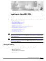
Installing the Cisco ONS 15530
2-1
Before Installing 2-1
Unpacking and Inspecting the Shelf
Mounting the Shelf 2-2
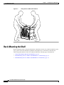
Chassis-Lifting Guidelines
1-21
2-2
2-2
Rack-Mounting the Shelf 2-4
General Rack-Mount Installation Guidelines 2-5
Flush-Mounting the Cisco ONS 15530 CHAS-N in a 19-Inch Rack 2-5
Flush-Mounting the Cisco ONS 15530 CHAS-E in a 21-Inch Rack 2-7
Attaching the Air Ramp Baffle 2-10
Installing the Fiber Routing Management System 2-12
Installing the Fiber Routing Tray 2-13
Installing the Fiber Routing Drawer 2-14
Grounding the Shelf 2-14
Shelf Grounding Guidelines 2-14
Shelf Grounding Procedures 2-14
Preventing ESD Damage 2-17
Installing and Removing Line Cards or Motherboards 2-17
Installing Line Cards or Motherboards 2-17
Removing Line Cards or Motherboards 2-18
Installing SFPs into Aggregation Cards and Muxponders
Installing SFP with Mini SMB Coax Connectors 2-18
2-18
Cisco ONS 15530 Hardware Installation Guide
iv
OL-7706-01
Contents
Removing SFP from Aggregation Cards and Muxponders 2-19
Removing Pull Tab SFPs with RJ-45 Connectors 2-19
Removing Non-Pull Tab SFPs with RJ-45 Connectors 2-20
Removing SFP Optics with MT-RJ Connectors 2-21
Removing SFP Optics with LC Connectors 2-23
Removing SFPs with Mini SMB Coax Connectors 2-24
Installing and Removing Modules 2-24
Installing OADM Modules and PSMs 2-24
Installing OSC Modules, WB-VOA Modules, and PB-OE Modules
Removing Modules 2-26
Replacing the Fan Assembly
2-27
Power Guidelines 2-29
Power Connection Guidelines for DC-Powered Systems
Plant Wiring Guidelines 2-30
Interference Considerations 2-30
Cabling Guidelines 2-31
Powering Up the Shelf 2-31
Connecting DC-Input Power 2-32
Connecting AC-Input Power 2-33
Installing and Removing the Power Supplies
CHAPTER
3
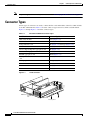
Connecting the Cisco ONS 15530
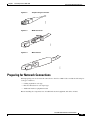
Connector Types
2-25
2-30
2-35
3-1
3-2
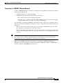
Preparing for Network Connections
3-3
Cleaning the Shelf and Connectors
3-4
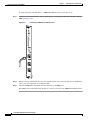
Connecting the CPU Switch Module 3-5
Ethernet Network Management Cable Connections 3-5
Connecting to a 10BASE-T Ethernet Network 3-5
Connecting to a 100BASE-T Ethernet Network 3-7
Connecting a Terminal to the Console Port 3-9
Auxiliary Modem Connection 3-11
Connecting the OSC Module
3-13
Connecting the PSM 3-14
Cabling PSMs 3-15
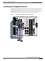
Connecting the Transponder Line Card
Connecting the OADM Module
3-17
3-19
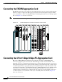
Connecting the ESCON Aggregation Card
3-20
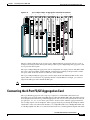
Connecting the 4-Port 1-Gbps/2-Gbps FC Aggregation Card
3-20
Cisco ONS 15530 Hardware Installation Guide
OL-7706-01
v
Contents
Connecting the 8-Port FC/GE Aggregation Card
Connecting the 8-Port Multi-Service Muxponder
Connecting the 2.5-Gbps ITU Trunk Card
3-21
3-23
3-24
Connecting the 10-Gbps ITU Tunable and Non tunable Trunk Card
Connecting the 10-Gbps Uplink Card
3-26
3-28
Connecting the WB-VOA and PB-OE Modules 3-28
Per-Channel Equalization 3-29
WB-VOA Attenuation on the Receive Side 3-30
WB-VOA on the Trunk 3-31
PB-OE on the Trunk to Equalizing Add Channel Power to Pass Through Power
Using PB-OE Modules to Terminate Unused Bands 3-33
Connecting a Multi-Shelf Node
Cable Management
APPENDIX
A
Specifications
3-32
3-34
3-39
A-1
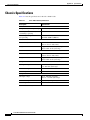
Chassis Specifications
A-2
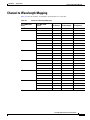
Channel to Wavelength Mapping
OADM Module Specifications
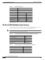
PSM Specifications
A-3
A-4
A-5
OSC Module Specifications
A-5
PB-OE and WB-VOA Module Specifications
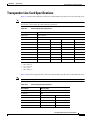
Transponder Line Card Specifications
A-7
ESCON Aggregation Card Specifications
A-8
4-Port 1-Gbps/2-Gbps FC Aggregation Card
8-Port FC/GE Aggregation Card
A-6
A-9
A-10
8-Port Multi-Service Muxponder Specifications
SDI Jitter Performance A-14
2.5-Gbps ITU Trunk Card Specifications
A-12
A-14
10-Gbps ITU Tunable and Non tunable Trunk Card Specifications
10-Gbps Uplink Card
SFP Specifications
A-15
A-16
A-16
INDEX
Cisco ONS 15530 Hardware Installation Guide
vi
OL-7706-01
Preface
This preface describes the audience, new and changed information, organization, and conventions of the
Cisco ONS 15530 Hardware Installation Guide. It also provides information about how to obtain related
documentation and technical assistance.
The information contained in this document pertains to the entire range of hardware supported on the
Cisco ONS 15530 platform. As new hardware and Cisco IOS software releases are made available for
the Cisco ONS 15530 platform, verification of compatibility becomes extremely important. To ensure
that your Cisco IOS software release supports your hardware, see the New and Changed Information
section. Also refer to the “Hardware Supported” section of the latest release notes for the
Cisco ONS 15530.
Audience
This guide is intended for experienced network administrators who are responsible for installing and
maintaining the Cisco ONS 15530.
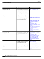
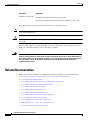
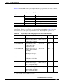
New and Changed Information
The table in this section lists and briefly describes the ongoing new and changed hardware features for
the Cisco ONS 15530 by Cisco IOS software release. Additionally, it shows the location of the new
feature information in this guide.
Cisco ONS 15530 Hardware Installation Guide
OL-7706-01
vii
Preface
New and Changed Information
Feature
Release
Description
Location
4-channel tunable
10-Gbps ITU trunk card
12.2(26)SV
If the 10-Gbps ITU trunk cards are
equipped with Universal Transponders
(UT1) that have tunable lasers, the cards
are programmable to one of the four
supported frequencies belonging to one
of the following bands: A, B, C, D, E, F,
G, or H.
“10-Gbps ITU Tunable Trunk
Cards” section on page 1-42
8-port multi-service
muxponder
12.2(25)SV
The 8-port multi-service muxponder
transports a mix of different protocols
between sites in a metro DWDM network.
The protocols that can be aggregated and
transported range from high-speed
services to low-speed services.
“8-Port Multi-Service
Muxponders” section on page 1-33
“Installing SFPs into Aggregation
Cards and Muxponders” section on
page 2-18
“Installing SFP with Mini SMB
Coax Connectors” section on
page 2-18
“Connecting the 8-Port
Multi-Service Muxponder” section
on page 3-23
“8-Port Multi-Service Muxponder
Specifications” section on
page A-12
“SFP Specifications” section on
page A-16
4-port 1-Gbps/2-Gbps
FC aggregation card
12.2(23)SV
The Cisco ONS 15530 supports a 4-port
1-Gbps/2-Gbps FC aggregation card for
Fibre Channel(FC), FICON, or ISC
traffic.
“4-Port 1-Gbps/2-Gbps FC
Aggregation Cards” section on
page 1-27
“Connecting the 4-Port
1-Gbps/2-Gbps FC Aggregation
Card” section on page 3-20
“4-Port 1-Gbps/2-Gbps FC
Aggregation Card” section on
page A-9
Variable rate SFP optics
12.1(12c)EV3
Variable rate SFP optics are available for “ESCON Aggregation Cards”
the ESCON aggregation card and the
section on page 1-25
8-port FC/GE aggregation card.
“8-Port FC/GE Aggregation
Cards” section on page 1-30
8-port FC/GE
aggregation card
12.1(12c)EV
The Cisco ONS 15530 supports an 8-port “8-Port FC/GE Aggregation
Fibre Channel/Gigabit Ethernet
Cards” section on page 1-30
aggregation card for FC and GE traffic.
“Connecting the 8-Port FC/GE
Aggregation Card” section on
page 3-21
Cisco ONS 15530 Hardware Installation Guide
viii
OL-7706-01
Preface
Organization
Feature
Release
Description
Location
2.5-Gbps ITU trunk
cards
12.1(12c)EV
2.5-Gbps ITU trunk card sends and
receives the ITU grid wavelength signal
to and from an OADM module.
“2.5-Gbps ITU Trunk Cards”
section on page 1-36
PSM (protection switch module) provides
trunk fiber protection.
“PSMs” section on page 1-15
Protection switch
module
12.1(12c)EV
“Connecting the 2.5-Gbps ITU
Trunk Card” section on page 3-24
“Cabling PSMs” section on
page 3-15
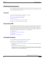
Organization
This guide describes how to install the Cisco ONS 15530 and is organized as follows:
Chapter
Title
Description
Chapter 1
Cisco ONS 15530 Overview
Describes the Cisco ONS 15530 chassis and its
components
Chapter 2
Installing the Cisco ONS 15530
Describes how to install the Cisco ONS 15530
chassis and its components
Chapter 3
Connecting the
Cisco ONS 15530
Describes how to install and route the cable
connectors in the Cisco ONS 15530
Appendix A Specifications
Lists the specifications for the Cisco ONS 15530
chassis and components
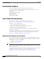
Conventions
This document uses the following conventions for notes, cautions, and safety warnings.
Convention
Application
boldface
Commands and keywords in body text.
italic
Command input that is supplied by the user.
[
Keywords or arguments that appear within square brackets are optional.
]
{x|x|x}
A choice of keywords (represented by x) appears in braces separated by
vertical bars. The user must select one.
Ctrl
The control key. For example, where Ctrl + D is written, hold down the
Control key while pressing the D key.
screen font
Examples of information displayed on the screen.
Cisco ONS 15530 Hardware Installation Guide
OL-7706-01
ix
Preface
Related Documentation
Convention
Application
boldface screen font
Examples of information that the user must enter.
<
Command parameters that must be replaced by module-specific codes.
>
Notes and Cautions contain important information that you should be aware of.
Note
Caution
Means reader take note. Notes contain helpful suggestions or references to material not
covered in the publication.
Means reader be careful. You are capable of doing something that might result in equipment damage or
loss of data.
Safety warnings appear throughout this publication in procedures that, if performed incorrectly, may
harm you. A warning symbol precedes each warning statement.
Warning
This warning symbol means danger. You are in a situation that could cause bodily injury. Before you
work on any equipment, be aware of the hazards involved with electrical circuitry and be familiar
with standard practices for preventing accidents. To see translations of the warnings that appear in
this publication, refer to the Regulatory Compliance and Safety Information document that
accompanied this device.
Related Documentation
Refer to the following documents for additional information about the Cisco ONS 15530 system:
•
Regulatory Compliance and Safety Information for the Cisco ONS 15500 Series
•
Cisco ONS 15530 Planning Guide
•
Cisco ONS 15530 Cleaning Procedures for Fiber Optic Connections
•
Cisco ONS 15530 Optical Turn-Up and Test Guide
•
Cisco ONS 15530 Configuration Guide
•
Cisco ONS 15530 Command Reference
•
Cisco ONS 15530 TL1 Command Reference
•
Cisco ONS 15530 System Alarms and Error Messages
•
Cisco ONS 15530 Troubleshooting Guide
•
Network Management for the Cisco ONS 15530
•
MIB Quick Reference for the Cisco ONS 15500 Series
•
Cisco ONS 15530 Software Upgrade Guide
Cisco ONS 15530 Hardware Installation Guide
x
OL-7706-01
Preface
Obtaining Documentation
Obtaining Documentation
Cisco documentation and additional literature are available on Cisco.com. Cisco also provides several
ways to obtain technical assistance and other technical resources. These sections explain how to obtain
technical information from Cisco Systems.
Cisco.com
You can access the most current Cisco documentation at this URL:
http://www.cisco.com/univercd/home/home.htm
You can access the Cisco website at this URL:
http://www.cisco.com
You can access international Cisco websites at this URL:
http://www.cisco.com/public/countries_languages.shtml
Documentation DVD
Cisco documentation and additional literature are available in a Documentation DVD package, which
may have shipped with your product. The Documentation DVD is updated regularly and may be more
current than printed documentation. The Documentation DVD package is available as a single unit.
Registered Cisco.com users (Cisco direct customers) can order a Cisco Documentation DVD (product
number DOC-DOCDVD=) from the Ordering tool or Cisco Marketplace.
Cisco Ordering tool:
http://www.cisco.com/en/US/partner/ordering/
Cisco Marketplace:
http://www.cisco.com/go/marketplace/
Ordering Documentation
You can find instructions for ordering documentation at this URL:
http://www.cisco.com/univercd/cc/td/doc/es_inpck/pdi.htm
You can order Cisco documentation in these ways:
•
Registered Cisco.com users (Cisco direct customers) can order Cisco product documentation from
the Ordering tool:
http://www.cisco.com/en/US/partner/ordering/
•
Nonregistered Cisco.com users can order documentation through a local account representative by
calling Cisco Systems Corporate Headquarters (California, USA) at 408 526-7208 or, elsewhere in
North America, by calling 1 800 553-NETS (6387).
Cisco ONS 15530 Hardware Installation Guide
OL-7706-01
xi
Preface
Documentation Feedback
Documentation Feedback
You can send comments about technical documentation to [email protected].
You can submit comments by using the response card (if present) behind the front cover of your
document or by writing to the following address:
Cisco Systems
Attn: Customer Document Ordering
170 West Tasman Drive
San Jose, CA 95134-9883
We appreciate your comments.
Cisco Product Security Overview
Cisco provides a free online Security Vulnerability Policy portal at this URL:
http://www.cisco.com/en/US/products/products_security_vulnerability_policy.html
From this site, you can perform these tasks:
•
Report security vulnerabilities in Cisco products.
•
Obtain assistance with security incidents that involve Cisco products.
•
Register to receive security information from Cisco.
A current list of security advisories and notices for Cisco products is available at this URL:
http://www.cisco.com/go/psirt
If you prefer to see advisories and notices as they are updated in real time, you can access a Product
Security Incident Response Team Really Simple Syndication (PSIRT RSS) feed from this URL:
http://www.cisco.com/en/US/products/products_psirt_rss_feed.html
Reporting Security Problems in Cisco Products
Cisco is committed to delivering secure products. We test our products internally before we release
them, and we strive to correct all vulnerabilities quickly. If you think that you might have identified a
vulnerability in a Cisco product, contact PSIRT:
Tip
•
Emergencies — [email protected]
•
Nonemergencies — [email protected]
We encourage you to use Pretty Good Privacy (PGP) or a compatible product to encrypt any sensitive
information that you send to Cisco. PSIRT can work from encrypted information that is compatible with
PGP versions 2.x through 8.x.
Never use a revoked or an expired encryption key. The correct public key to use in your correspondence
with PSIRT is the one that has the most recent creation date in this public key server list:
http://pgp.mit.edu:11371/pks/lookup?search=psirt%40cisco.com&op=index&exact=on
Cisco ONS 15530 Hardware Installation Guide
xii
OL-7706-01
Preface
Obtaining Technical Assistance
In an emergency, you can also reach PSIRT by telephone:
•
1 877 228-7302
•
1 408 525-6532
Obtaining Technical Assistance
For all customers, partners, resellers, and distributors who hold valid Cisco service contracts, Cisco
Technical Support provides 24-hour-a-day, award-winning technical assistance. The Cisco Technical
Support Website on Cisco.com features extensive online support resources. In addition, Cisco Technical
Assistance Center (TAC) engineers provide telephone support. If you do not hold a valid Cisco service
contract, contact your reseller.
Cisco Technical Support Website
The Cisco Technical Support Website provides online documents and tools for troubleshooting and
resolving technical issues with Cisco products and technologies. The website is available 24 hours a day,
365 days a year, at this URL:
http://www.cisco.com/techsupport
Access to all tools on the Cisco Technical Support Website requires a Cisco.com user ID and password.
If you have a valid service contract but do not have a user ID or password, you can register at this URL:
http://tools.cisco.com/RPF/register/register.do
Note
Use the Cisco Product Identification (CPI) tool to locate your product serial number before submitting
a web or phone request for service. You can access the CPI tool from the Cisco Technical Support
Website by clicking the Tools & Resources link under Documentation & Tools. Choose Cisco Product
Identification Tool from the Alphabetical Index drop-down list, or click the Cisco Product
Identification Tool link under Alerts & RMAs. The CPI tool offers three search options: by product ID
or model name; by tree view; or for certain products, by copying and pasting show command output.
Search results show an illustration of your product with the serial number label location highlighted.
Locate the serial number label on your product and record the information before placing a service call.
Submitting a Service Request
Using the online TAC Service Request Tool is the fastest way to open S3 and S4 service requests. (S3
and S4 service requests are those in which your network is minimally impaired or for which you require
product information.) After you describe your situation, the TAC Service Request Tool provides
recommended solutions. If your issue is not resolved using the recommended resources, your service
request is assigned to a Cisco TAC engineer. The TAC Service Request Tool is located at this URL:
http://www.cisco.com/techsupport/servicerequest
For S1 or S2 service requests or if you do not have Internet access, contact the Cisco TAC by telephone.
(S1 or S2 service requests are those in which your production network is down or severely degraded.)
Cisco TAC engineers are assigned immediately to S1 and S2 service requests to help keep your business
operations running smoothly.
Cisco ONS 15530 Hardware Installation Guide
OL-7706-01
xiii
Preface
Obtaining Additional Publications and Information
To open a service request by telephone, use one of the following numbers:
Asia-Pacific: +61 2 8446 7411 (Australia: 1 800 805 227)
EMEA: +32 2 704 55 55
USA: 1 800 553-2447
For a complete list of Cisco TAC contacts, go to this URL:
http://www.cisco.com/techsupport/contacts
Definitions of Service Request Severity
To ensure that all service requests are reported in a standard format, Cisco has established severity
definitions.
Severity 1 (S1)—Your network is “down,” or there is a critical impact to your business operations. You
and Cisco will commit all necessary resources around the clock to resolve the situation.
Severity 2 (S2)—Operation of an existing network is severely degraded, or significant aspects of your
business operation are negatively affected by inadequate performance of Cisco products. You and Cisco
will commit full-time resources during normal business hours to resolve the situation.
Severity 3 (S3)—Operational performance of your network is impaired, but most business operations
remain functional. You and Cisco will commit resources during normal business hours to restore service
to satisfactory levels.
Severity 4 (S4)—You require information or assistance with Cisco product capabilities, installation, or
configuration. There is little or no effect on your business operations.
Obtaining Additional Publications and Information
Information about Cisco products, technologies, and network solutions is available from various online
and printed sources.
•
Cisco Marketplace provides a variety of Cisco books, reference guides, and logo merchandise. Visit
Cisco Marketplace, the company store, at this URL:
http://www.cisco.com/go/marketplace/
•
Cisco Press publishes a wide range of general networking, training and certification titles. Both new
and experienced users will benefit from these publications. For current Cisco Press titles and other
information, go to Cisco Press at this URL:
http://www.ciscopress.com
•
Packet magazine is the Cisco Systems technical user magazine for maximizing Internet and
networking investments. Each quarter, Packet delivers coverage of the latest industry trends,
technology breakthroughs, and Cisco products and solutions, as well as network deployment and
troubleshooting tips, configuration examples, customer case studies, certification and training
information, and links to scores of in-depth online resources. You can access Packet magazine at
this URL:
http://www.cisco.com/packet
Cisco ONS 15530 Hardware Installation Guide
xiv
OL-7706-01
Preface
Obtaining Additional Publications and Information
•
iQ Magazine is the quarterly publication from Cisco Systems designed to help growing companies
learn how they can use technology to increase revenue, streamline their business, and expand
services. The publication identifies the challenges facing these companies and the technologies to
help solve them, using real-world case studies and business strategies to help readers make sound
technology investment decisions. You can access iQ Magazine at this URL:
http://www.cisco.com/go/iqmagazine
•
Internet Protocol Journal is a quarterly journal published by Cisco Systems for engineering
professionals involved in designing, developing, and operating public and private internets and
intranets. You can access the Internet Protocol Journal at this URL:
http://www.cisco.com/ipj
•
World-class networking training is available from Cisco. You can view current offerings at
this URL:
http://www.cisco.com/en/US/learning/index.html
Cisco ONS 15530 Hardware Installation Guide
OL-7706-01
xv
Preface
Obtaining Additional Publications and Information
Cisco ONS 15530 Hardware Installation Guide
xvi
OL-7706-01
C H A P T E R
1
Cisco ONS 15530 Overview
The Cisco ONS 15530 is a modular and scalable optical switching and aggregation platform designed to
supplement the Cisco ONS 15540 ESP. With the Cisco ONS 15530, users can take advantage of the
availability of dark fiber to build a common infrastructure that supports data, storage area network
(SAN), and time-division multiplexing(TDM) traffic. For more information about DWDM technology
and applications, refer to the Introduction to DWDM Technology publication and the
Cisco ONS 15530 Planning Guide.
The Cisco ONS 15530 is designed to meet or exceed stringent ISP (Internet service provider)
requirements for product availability and reliability.
Note
Before you install, operate, or service the system, read the Regulatory Compliance and Safety
Information for the Cisco ONS 15500 Series for important safety information you should know before
working with the system.
This chapter includes the following sections:
•
Cisco ONS 15530 Chassis, page 1-2
•
Cisco ONS 15530 Components, page 1-10
Cisco ONS 15530 Hardware Installation Guide
OL-7706-01
1-1
Chapter 1
Cisco ONS 15530 Overview
Cisco ONS 15530 Chassis
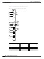
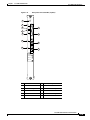
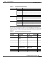
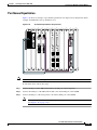
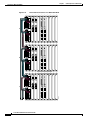
Cisco ONS 15530 Chassis
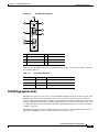
The Cisco ONS 15530 is available in two configurations. Both have two vertically stacked half-height
slots specifically for the optical OADM (optical add/drop multiplexing) modules, and 10 vertically
oriented slots that hold the CPU switch modules, line cards, and 2.5-G transponder trunk line cards.
Slot 0 holds two half height optical OADM modules. Slots 1 through 4 and slots 7 through 10 hold the
line cards and transponder cards. Slots 5 and 6 hold the CPU switch modules. Power supplies are located
on the right side of the chassis next to slot 10. Air inlet and fan tray assembly are located beneath the
slots. Cable management is located beneath the slots. The system has an electrical backplane for system
control. All optical connections are located on the front of the cards. Figure 1-1 shows a fully populated
chassis.
Figure 1-1
Cisco ONS 15530 Shelf
US
AT
US
ST
AT
T
X
R
X
3
X
S
FD
BP
0M
10
K
LIN
T
X
R
X
N
CO
T
X
R
X
T
X
R
X
T
X
R
X
0
T
X
R
X
1
T
X
R
X
2
1
T
X
R
X
E
A
S
T
2
T
X
3
T
X
R
X
3
W
E
S
T
T
X
R
X
T
X
R
X
4
5
6
T
X
R
X
4
T
X
R
X
5
T
X
R
X
6
T
X
R
X
4
T
X
R
X
5
T
X
R
X
6
7
7
T
X
R
X
7
8
T
X
R
X
8
T
X
R
X
8
X
AU
T
X
R
X
9
T
X
R
X
FASTENERS
FULLY ENGA MUST BE
OPERATING GED PRIOR TO
THE POWE
R SUPPLY
GOOD
9
15530-LCMB-0200
15530-LCMB-0200
15530-LCMB-0200
15530-CPU
15530-CPU
15530-LCMB-0200
15530-LCMB-0200
9
FAIL
100-240V
8.0-3.5A
50-60HZ
T
X
R
X
X
AU
T
X
R
X
0
T
X
R
X
R
X
T
X
R
X
8
9
T
X
R
X
S
N U
FA TAT
S
77670
T
X
R
X
T
X
R
X
N
CO
T
X
R
X
US
7
T
X
R
X
2
ST
HI R
CL
FF
TO
CU
6
T
X
R
X
9
AT
AL
IC
RT
R
JO
MA
R
NO
CI
MI
T
X
R
X
ST
US
T
ACH
MPAS
CO FL
5
8
ST
AT
E
TIV
T
X
R
X
X
S
FD
BP
0M
10
K
LIN
7
T
X
R
X
4
A
L
A
R
M
S
ST
HI R
CL
6
T
X
R
X
T
X
R
X
T
X
R
X
A
L
A
R
M
S
N
CO
T
X
R
X
1
3
FF
TO
CU
5
0
T
X
R
X
T
X
R
X
FF
TO
CU
T
X
R
X
T
X
R
X
T
X
R
X
2
AL
IC
RT
R
JO
MA
R
X
4
1
T
X
R
X
CI
R
X
T
X
R
X
0
T
X
R
X
AC
3
T
X
T
SE
RE
2
T
X
R
X
T
ACH
MPAS
CO FL
T
X
R
X
T
X
R
X
T
X
ST
US
1
E
TIV
AC
0
T
X
R
X
T
R
X
T
X
R
X
SE
RE
W
E
S
T T
X
AT
E
A
S
T T
X
T R
X X
R
X
ST
US
R
X
AT
R
X
ST
T
X
US
T
X
AT
R
X
US
W
E
S
T T
X
ST
US
AT
AT
ST
US
ST
AT
ST
E
A
S
T T
X
T R
X X
R
X
The chassis configurations differ in how cooling air is routed through the chassis and where the lifting
handles are placed.
Cisco ONS 15530 Hardware Installation Guide
1-2
OL-7706-01
Chapter 1
Cisco ONS 15530 Overview
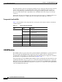
Cisco ONS 15530 Chassis
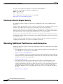
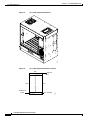
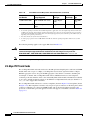
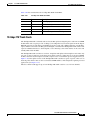
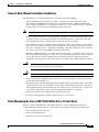
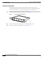
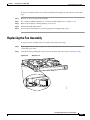
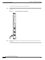
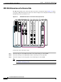
Cisco ONS 15530-CHAS-E Chassis
The dimensions of the Cisco ONS 15530 CHAS-E chassis are 14.4 x 17.3 x 10.1 inches (H x W x D)
See Figure 1-2. Handles for lifting the chassis are located on the sides.
Cisco ONS 15530 CHAS-E Chassis
77080
F
ST AN
AT
U
S
Figure 1-2
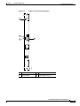
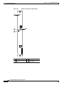
The fan assembly draws in cooling air through the air ramp baffle (see Figure 1-3) on the bottom of the
chassis, pushing the air across the internal components and out the exhaust baffles on the top of the
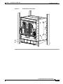
chassis.
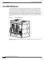
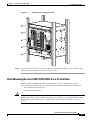
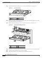
The air ramp baffle for the Cisco ONS 15530 CHAS-E chassis redirects the cooling air intake as shown
in Figure 1-4. The air ramp baffle must be installed when installing the Cisco ONS 15530 CHAS-E type
chassis.
Cisco ONS 15530 Hardware Installation Guide
OL-7706-01
1-3
Chapter 1
Cisco ONS 15530 Overview
Cisco ONS 15530 Chassis
Cisco ONS 15530 CHAS-E (with Air Ramp Baffle)
77825
F
ST AN
AT
U
S
Figure 1-3
Cisco ONS 15530 Hardware Installation Guide
1-4
OL-7706-01
Chapter 1
Cisco ONS 15530 Overview
Cisco ONS 15530 Chassis
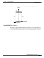
Figure 1-4
Cisco ONS 15530 CHAS-E Chassis Airflow (with Air Ramp Baffle Installed)
Exhaust
air
Top
Rear
Front
Bottom
77824
Fan assembly
Air ramp baffle
Ambient air
intake
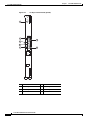
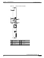
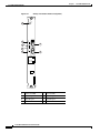
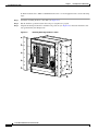
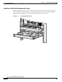
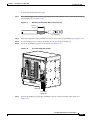
Cisco ONS 15530 CHAS-N Chassis
The dimensions of the Cisco ONS 15530 CHAS-N chassis are 14.4 x 15.7 x 10.1 inches (H x W x D).
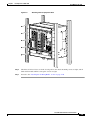
(See Figure 1-5.) Handles for lifting the chassis are located on the top. The fan assembly draws in
cooling air through the intake baffles on the front of the chassis, below the fan assembly, pushing the air
over the internal components and out the exhaust on the top rear and sides of the chassis (see Figure 1-6).
Cisco ONS 15530 Hardware Installation Guide
OL-7706-01
1-5
Chapter 1
Cisco ONS 15530 Overview
Cisco ONS 15530 Chassis
Cisco ONS 15530 CHAS-N Chassis
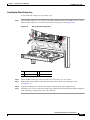
Figure 1-6
Cisco ONS 15530 CHAS-N Chassis Airflow
77081
F
ST AN
AT
U
S
Figure 1-5
Top
Exhaust
air
Ambient air
intake
Fan assembly
Bottom
77668
Rear
Front
Cisco ONS 15530 Hardware Installation Guide
1-6
OL-7706-01
Chapter 1
Cisco ONS 15530 Overview
Cisco ONS 15530 Chassis
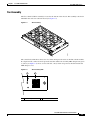
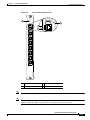
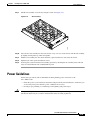
Fan Assembly
The Cisco ONS 15530 fan assembly is located at the bottom of the chassis. The assembly contains six
individual fans and a fan controller board (see Figure 1-7).
Figure 1-7
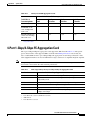
Fan Assembly
77834
N US
FA TAT
S
The controller board monitors the status of each fan and reports the status to the CPU switch modules.
If a single fan fails, a minor alarm is reported to the CPU and the fan assembly LED changes from green
to yellow (see Figure 1-8). If two or more fans fail, a major alarm is reported to the CPU and the fan
LED changes to red.
Figure 1-8
2
77796
1
Fan Assembly LED
1
Fan assembly LED
2
Alarm connector
Cisco ONS 15530 Hardware Installation Guide
OL-7706-01
1-7
Chapter 1
Cisco ONS 15530 Overview
Cisco ONS 15530 Chassis
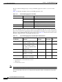
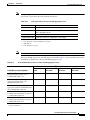
Table 1-1 lists the fan assembly LED status describing the alarm reports for the fan assembly. The fan
assembly is hot-swappable.
Table 1-1
Fan Assembly Status
Fan Failure
LED
Status
None
Green
Normal
One
Yellow
Minor
Two or more
Red
Major
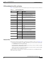
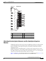
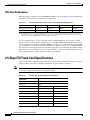
Audible and Visible Alarms
The Cisco ONS 15530 provides audible and visible alarm status to the Telco central office alarm
equipment through hardware located on the fan assembly (see Figure 1-8). Software determines the
alarm condition and sets the appropriate relays for critical, major, or minor alarms. Table 1-2 lists the
terminal block pinouts.
Table 1-2
Connector
Terminal Block Pinouts
Alarm Type
Level
Pin
1
Critical
P1
Visible
Major
Minor
Critical
P2
Audible
Major
Minor
Contact
C
1
2
2
NC
3
NO3
4
C
5
NC
6
NO
7
C
8
NC
9
NO
1
C
2
NC
3
NO
4
C
5
NC
6
NO
7
C
8
NC
9
NO
Notes
Each type and level of
alarm is signaled by a
contact closure of C
to NO and an open
from C to NC.
Voltage at contacts is
limited to 48 VDC.
Switched current /
load is limited to 1-A
resistive.
Alarms are signaled
when the chassis is
unpowered.
1. C = center
2. NC = normally closed
3. NO = normally open
Cisco ONS 15530 Hardware Installation Guide
1-8
OL-7706-01
Chapter 1
Cisco ONS 15530 Overview
Cisco ONS 15530 Chassis
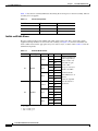
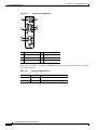
Power Supplies
The Cisco ONS 15530 chassis supports redundant 120–240 VAC (see Figure 1-9) or –48 VDC
(see Figure 1-10) power. The power supplies are located at the right of the chassis, next to the card slots
(see Figure 1-1). Up to two power supplies can be installed for redundancy.
Figure 1-9
120–240 VAC Power Supply
FASTENERS MUST BE
FULLY ENGAGED PRIOR TO
OPERATING THE POWER SUPPLY
FAIL
GOOD
~
77894
100-240V
8.0- 3.5A
50-60 HZ
Figure 1-10
–48 VDC Power Supply
FASTENERS MUST BE
FULLY ENGAGED PRIOR TO
OPERATING THE POWER SUPPLY
FAIL GOOD
77893
-48 TO -60V
17/A
See the “Powering Up the Shelf” section on page 2-31 for more information about the power supplies.
Cisco ONS 15530 Hardware Installation Guide
OL-7706-01
1-9
Chapter 1
Cisco ONS 15530 Overview
Cisco ONS 15530 Components
Backplane
The Cisco ONS 15530 backplane implements all board-to-board signal interconnects and provides
power distribution within the chassis. Connections are present for two power supplies and the fan
assembly. The backplane contains a total of 12 slots; two half-height slots for the OADM modules, two
full height slots for the CPU switch modules, and eight full height slots for line cards and transponder
cards.
Cable Storage Drawer
The cable storage drawer is mounted directly below the fan assembly. It provides storage for the excess
cable length. Sliding radius limiters move to release the excess fiber cable slack when the drawer is
pulled out, allowing the user to raise the fiber routing tray and access the fan assembly.
Version Identification Labels
The version identifier on a 4-port 1-Gbps/2-Gbps FC aggregation card is located on the inside of the
card. We reccommend that you record the version ID in a safe place before installing the card. You can
also use the show hardware and show inventory commands to verify the version ID of the card.
Cisco ONS 15530 Components
The following hardware components can be installed in the Cisco ONS 15530:
Note
•
CPU Switch Modules, page 1-11
•
OSC Modules and Carrier Motherboards, page 1-14
•
PSMs, page 1-15
•
Transponder Line Cards, page 1-17
•
OADM Modules, page 1-20
•
Wide-Band Variable Optical Attenuator and Per-Band Optical Equalizer Modules, page 1-21
•
ESCON Aggregation Cards, page 1-25
•
4-Port 1-Gbps/2-Gbps FC Aggregation Cards, page 1-27
•
8-Port FC/GE Aggregation Cards, page 1-30
•
8-Port Multi-Service Muxponders, page 1-33
•
2.5-Gbps ITU Trunk Cards, page 1-36
•
10-Gbps ITU Trunk Cards, page 1-39
•
10-Gbps ITU Tunable Trunk Cards, page 1-42
•
10-Gbps Uplink Cards, page 1-45
To ensure that your release of Cisco IOS software supports your hardware, see the “New and Changed
Information” section on page vii. Also refer to the “Hardware Supported” section of the latest release
notes for the Cisco ONS 15530.
Cisco ONS 15530 Hardware Installation Guide
1-10
OL-7706-01
Chapter 1
Cisco ONS 15530 Overview
Cisco ONS 15530 Components
CPU Switch Modules
The Cisco ONS 15530 supports two CPU switch modules for redundancy, one in active mode and the
other in hot-standby mode. CPU switch modules are installed in slot 5 and slot 6. Each CPU switch
module has a processor, a switch fabric, a clock, an Ethernet switch for communication between
processors and with the LRC (line card redundancy controller) on the OADM modules and line cards,
and an SRC (switch card redundancy controller). The active processor controls the system. All LRCs in
the system use the system clock and synchronization signals from the active processor. Interfaces on the
CPU switch modules permit access by 10/100 Ethernet, console terminal, or modem connections.
Cisco ONS 15530 Hardware Installation Guide
OL-7706-01
1-11
Chapter 1
Cisco ONS 15530 Overview
Cisco ONS 15530 Components
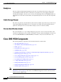
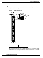
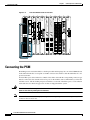
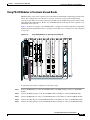
Figure 1-11 shows the front panel of the CPU switch module.
Figure 1-11
Cisco ONS 15530 CPU Switch Module
ST
AT
U
S
1
2
R
ES
ET
3
AC
ST
4
TI
V
BY E
AN
D
5
C
O
FL MP
AS AC
H T
7
6
9
FF
11
10
T
C
U
12
H
C IST
LR
TO
FF
13
8
C
A
M
IN MA IRT
L
JO
O
IC
R
AL
R
A
R
M CU
TO HI
S
S
N
M
E
15
14
LI
N
K
10
16
FD
0M
X
BP
S
17
C
O
N
18
AU
X
77664
15530-CPU
1
Card status LED
7
Major alarm LED
13 NME port
2
Reset button
8
Critical alarm LED
14 Link LED
3
Standby LED
9
Cutoff LED
15 100 Mbps LED
4
Active LED
10 HIST LED
16 Full-duplex LED
5
CompactFlash card slot
11 Cutoff LED
17 Console port
6
Minor alarm LED
12 HIST CLR LED
18 Auxiliary port
Cisco ONS 15530 Hardware Installation Guide
1-12
OL-7706-01
Chapter 1
Cisco ONS 15530 Overview
Cisco ONS 15530 Components
CPU Switch Module Ports, LEDs, and Switches
Table 1-3 lists the LEDs on the CPU switch module faceplate with a description of the status indication.
Table 1-3
CPU Switch Module LEDs
LED
Status
Description
STATUS
Green
IOS is loaded and running.
Yellow
Card is in the process of booting.
ACTIVE
Green
Module is the primary CPU switch
module, otherwise the LED is off.
STANDBY
Green
Module is in standby mode, otherwise the
LED is off.
CRITICAL
Red
A system wide critical alarm exists.
MAJOR
Yellow
A system wide major alarm exists.
MINOR
Yellow
A system wide minor alarm exists.
HIST
Yellow
A system wide major or minor alarm has
occurred.
HIST CLR
Yellow
A system wide major or minor alarm has
occurred.
CUTOFF
Red
A major or minor alarm exists and the
cutoff button has been pushed.
FDX
Green
Module is running full-duplex.
Off
Module is running half-duplex.
Green
Module is running at 100 Mbps.
Off
Module is running at 10 Mbps.
Green
Link is up.
Off
Link is down.
ALARM LEDs
100MBPS
LINK
Connector Ports
The front panel on the CPU switch module contains three ports with RJ-45 connectors (see Figure 1-11):
•
Network Management Ethernet port (NME)—This Ethernet port connects the CPU switch module
to a 10/100BASE-T network management LAN.
•
Console port (CON)—This asynchronous EIA/TIA-232 serial port connects a terminal to the CPU
switch module for local administrative access.
•
Auxiliary port (AUX)—This asynchronous EIA/TIA-232 serial port connects a modem to the CPU
switch module for remote administrative access.
The RJ-45 connectors on the front panel of the CPU switch module have an extra EMI shield and the
signals going to them are filtered.
Cisco ONS 15530 Hardware Installation Guide
OL-7706-01
1-13
Chapter 1
Cisco ONS 15530 Overview
Cisco ONS 15530 Components
Table 1-4 shows the pinouts of the console and auxiliary ports.
Table 1-4
Console and Auxiliary Port RJ-45 Pinout
Pin No.
Console
Direction
Function
Auxiliary
Direction
Function
1
Output
RTS
Request To Send
Output
RTS
Request To Send
2
Output
DTR
Data terminal ready
Output
DTR
Data terminal ready
3
Output
TxD
Transmit data
Output
TxD
Transmit data
4
N/A
GND
Ground
N/A
GND
Ground
5
N/A
GND
Ground
N/A
GND
Ground
6
Input
RxD
Receive data
Input
RxD
Receive data
7
Input
DSR
Data set ready
Input
CD
Carrier Detect
8
Input
CTS
Clear To Send
Input
CTS
Clear To Send
CompactFlash Card Slot
A CompactFlash card slot (see Figure 1-11) can store the Cisco IOS image or a system configuration file
on a CompactFlash memory card. The system can also boot from the software stored on the
CompactFlash memory card.
OSC Modules and Carrier Motherboards
The OSC (optical supervisory channel) module supports an optional out-of-band management channel
for communicating between systems on the network. Using a 33rd wavelength (channel 0), the OSC
allows control and management traffic to be carried without requiring a separate Ethernet connection to
each Cisco ONS 15530 in the network. Up to two OSC modules can be installed in the carrier
motherboard, one module for the west direction and one for the east direction.
The OSC always terminates on a neighboring node. By contrast, data channels may or may not be
terminated on a given node, depending on whether the channels on the OADM modules are treated as
either express (pass-through) or add/drop channels.
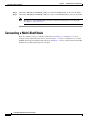
Figure 1-12 shows the front panel of the OSC module.
Cisco ONS 15530 Hardware Installation Guide
1-14
OL-7706-01
Chapter 1
Cisco ONS 15530 Overview
Cisco ONS 15530 Components
Figure 1-12
OSC Module
ST
AT
U
1
S
T
X
2
R
X
X
TX
4
15530-OSCM
5
77667
R
3
1
Card status LED
4
Transmit LED
2
OADM port
5
Card handle
3
Receive LED
OSC Module LEDs
Table 1-5 lists the LEDs on the OSC module faceplate, their default conditions, and what the conditions
indicate.
Table 1-5
OSC Module LEDs
LED
Status
Description
STATUS
Green
OSC module initialization process is complete.
Yellow
OSC module is in initialization process.
TX
Green
Transmit laser is enabled.
RX
Green
Light reception exists at wave OSC interface.
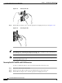
PSMs
The PSM (protection switch module) provides trunk fiber protection for Cisco ONS 15530 systems
configured in point-to-point topologies. The PSM sends the signal from an OADM module, an ITU trunk
card, or a transponder line card to both the west and east directions. It receives both the west and east signals
and sends to the OADM module, ITU trunk card, or transponder line card. Both nodes in the network topology
must have the same shelf configuration.When a trunk fiber cut occurs on the active path, the PSM switches
the received signal to the standby path. Because the PSM occupies one of the OADM subslots in the shelf, it
protects a maximum of four channels and the OSC in a single shelf configuration.
The PSM also has an optical monitor port for testing the west and east receive signals. This port samples
one percent of these signals, which can be monitored with an optical power meter or an optical spectrum
analyzer.
A PSM can be installed in subslots 0/0 and 0/1 of the Cisco ONS 15530 chassis.
Cisco ONS 15530 Hardware Installation Guide
OL-7706-01
1-15
Chapter 1
Cisco ONS 15530 Overview
Cisco ONS 15530 Components
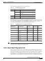
The PSM for the Cisco ONS 15530 has a front panel with four MU connector pairs, as shown in
Figure 1-13.
Figure 1-13
PSM
1
2
3
4
85519
5
1
Rx/Tx West ports
4
East and West optical monitor ports
2
Rx/Tx East ports
5
Common IN/OUT ports
3
East and West status LEDs
PSM LEDs
Table 1-6 lists the LEDs on the PSM faceplate, their default conditions, and what the conditions indicate.
Table 1-6
PSM LEDs
LED
Status
Description
Status
Green
Software initialization is successful.
Off
Board failure.
Cisco ONS 15530 Hardware Installation Guide
1-16
OL-7706-01
Chapter 1
Cisco ONS 15530 Overview
Cisco ONS 15530 Components
Transponder Line Cards
The protocol-transparent and bit-rate transparent transponder line card converts a single client signal
into an ITU wavelength, or channel. The transponder line cards have tunable lasers and you can
configure the line cards to work in two different wavelengths. The Cisco ONS 15530 holds up to four
transponder line cards, one for each wavelength supported by the OADM modules.
The Cisco ONS 15530 supports four types of single client interface transponder line cards: SM (single
mode) unprotected, SM splitter protected, MM (multimode) unprotected, and MM splitter protected.
Both types of SM transponder line cards accept SM client signals on the 1310-nm wavelength through
an SC connector and support client signal clock rates ranging from 16 Mbps to 2.5 Gbps. Both types of
MM transponder line cards accept SM and MM client signals on the 1310-nm wavelength through an
SC connector and support client signal clock rates ranging from 16 Mbps to 622 Mbps (see Figure 1-14
and Figure 1-15).
Cisco ONS 15530 Hardware Installation Guide
OL-7706-01
1-17
Chapter 1
Cisco ONS 15530 Overview
Cisco ONS 15530 Components
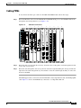
Figure 1-14
Transponder Line Card LEDs (Nonsplitter)
ST
AT
U
S
1
3
T
X
T
X
R
X
2
R
X
4
5
7
T
X
T
X
6
R
X
8
77659
R
X
1
Card status LED
5
Client side transmit LED
2
ITU side port
6
Client side transmit port
3
ITU transmit LED
7
Client side receive LED
4
ITU receive LED
8
Client side receive port
Cisco ONS 15530 Hardware Installation Guide
1-18
OL-7706-01
Chapter 1
Cisco ONS 15530 Overview
Cisco ONS 15530 Components
Figure 1-15
Transponder Line Card LEDs (Splitter)
ST
AT
U
S
1
2
4
5
6
8
10
W
E
S
T
T
X
3
R
X
T
X
R
X
E
A
S
T
T
X
7
R
X
T
X
R
X
T
X
9
R
X
11
W ITU TX
W ITU RX
E ITU TX
E ITU RX
1310 TX
77660
1310 RX
1
Card status LED
7
East side ITU port
2
West side ITU LED
8
Client side transmit LED
3
West side ITU port
9
Client side transmit port
4
ITU side transmit LED
10 Client side receive LED
5
ITU side receive LED
11 Client side receive port
6
East side ITU LED
Cisco ONS 15530 Hardware Installation Guide
OL-7706-01
1-19
Chapter 1
Cisco ONS 15530 Overview
Cisco ONS 15530 Components
The transponder line cards are hot swappable, permitting in-service upgrades and replacement. All client
signals on the transponders are supported in 3R (reshape, retime, retransmit) mode, regardless of
protocol encapsulation type. The client interfaces also support the OFC (open fiber control) safety
protocol for Fibre Channel, ISC compatibility mode, and FICON. The client side ports use SC-type
connectors.
On the trunk side, the transponder line card output laser power ranges from 5 to 10 dBm and the receive
detector has a sensitivity of –32 dBm. The ports on the trunk side use MU-type connectors.
Transponder Line Card LEDs
Table 1-7 lists the LEDs on the transponder line card faceplate, their default conditions, and what the
conditions indicate.
Table 1-7
Transponder Line Card LEDs
LED
Status
Description
STATUS
Green
Card is properly initialized.
Blinking green
Good system clock is present and card is
out of reset state.
Yellow
System clock is not present.
EAST1
Green
Card is listening to the east side signal.
TX (Trunk port)
Green
Port is up and transmit laser is enabled.
RX (Trunk port)
Green
Light reception exists at the port.
Green
Card is listening to the west side signal.
TX (Client port)
Green
Port is up and transmit laser is enabled.
RX (Client port)
Green
Light reception exists at the port.
WEST
1
1. This LED is only present on transponder line cards with splitter.
OADM Modules
The OADM modules are passive devices that optically multiplex and demultiplex a specific band of four
ITU wavelengths. The OADM modules supported by the Cisco ONS 15530 each add and drop a
specified band of four channels at a node and pass the other bands through. To support the 32-channel
spectrum, there are eight different 4-channel cards (see Figure 1-16).
In the transmit direction, the OADM modules multiplex signals transmitted by the transponder line cards
and 10-Gbps ITU trunk cards over optical cross connections and provide the interfaces to connect the
multiplexed signal to the DWDM trunk side. In the receive direction, the OADM modules demultiplex
the signals from the trunk side before passing them over optical cross connections to the transponder line
cards and 10-Gbps ITU trunk cards.
Cisco ONS 15530 Hardware Installation Guide
1-20
OL-7706-01
Chapter 1
Cisco ONS 15530 Overview
Cisco ONS 15530 Components
Figure 1-16
OADM Module
1
2
3
4
5
6
91400
7
1
Trunk IN/OUT ports
5
Data channel IN/OUT ports
2
Thru IN/OUT ports
6
Data channel IN/OUT ports
7
Data channel IN/OUT ports
1
3
OSC IN/OUT ports
4
Data channel IN/OUT ports
1. Only on OADM modules with OSC. These ports are not used on other modules.
Wide-Band Variable Optical Attenuator and Per-Band Optical Equalizer
Modules
The WB-VOA (wide-band variable optical attenuator) and PB-OE (per-band power equalizer) modules
are half-width modules that allow the ONS 15530 to extend the internodal and ring circumference
distances and number of nodes supported for point-to-point, hub ring, and mesh ring networks by
equalizing power levels.
The WB-VOA module and the PB-OE module are available in single and dual band versions. These
modules are installed into a carrier motherboard. This motherboard is installed into and operates on the
Cisco ONS 15530 chassis. The carrier motherboard can be installed in slots 1 to 4 or 7 to 10. All optical
connectors are located on the front panel and the connectors are angled.
Figure 1-17 and Figure 1-18 show the single and dual versions of the WB-VOA module. Figure 1-19 and
Figure 1-20 show the single-band and dual-band versions of the PB-OE module.
Cisco ONS 15530 Hardware Installation Guide
OL-7706-01
1-21
Chapter 1
Cisco ONS 15530 Overview
Cisco ONS 15530 Components
Figure 1-17
Single WB-VOA Module
15500-VOA-0100
PM1 STA
1
2
IN
3
OUT
4
79166
5
1
PM1 LED
4
OUT port
2
Card status LED
5
Handle
3
IN port
Table 1-8 lists the LEDs on the single WB-VOA module faceplate, their default conditions, and what the
conditions indicate.
Table 1-8
Single WB-VOA Module LEDs
LED
Status
Description
PM1
Green
Light reception exists at the port.
STA
Green
Card is properly initialized.
Cisco ONS 15530 Hardware Installation Guide
1-22
OL-7706-01
Chapter 1
Cisco ONS 15530 Overview
Cisco ONS 15530 Components
Figure 1-18
Dual WB-VOA Module
2
15500-VOA-0200
PM2 PM1 STA
1
3
IN1
4
OUT1
5
7
IN2
6
79168
OUT2
8
1
PM2 LED
5
OUT1 port
2
PM1 LED
6
Handle
3
Card status LED
7
IN2 port
4
IN1 port
8
OUT2 port
Table 1-9 lists the LEDs on the dual WB-VOA module faceplate, their default conditions, and what the
conditions indicate.
Table 1-9
Dual WB-VOA Module LEDs
LED
Status
Description
PM2
Green
Light reception exists at the port.
PM1
Green
Light reception exists at the port.
STATUS
Green
Card is properly initialized.
Cisco ONS 15530 Hardware Installation Guide
OL-7706-01
1-23
Chapter 1
Cisco ONS 15530 Overview
Cisco ONS 15530 Components
Figure 1-19
Single-Band PB-OE Module
1
2
3
4
5
6
79173
7
1
PM1 LED
5
OUT port
2
Card status LED
6
UPG IN port
3
IN port
7
UPG OUT port
4
Handle
Table 1-10 lists the LEDs on the single-band PB-OE module faceplate, their default conditions, and what
the conditions indicate.
Table 1-10
Single-Band PB-OE Module
LED
Status
Description
PM1
Green
Light reception exists at the port.
STA
Green
Card is properly initialized.
Cisco ONS 15530 Hardware Installation Guide
1-24
OL-7706-01
Chapter 1
Cisco ONS 15530 Overview
Cisco ONS 15530 Components
Figure 1-20
Dual-Band PB-OE Module
2
15500-PEQ-02EF
PM2 PM1 STA
1
3
IN
4
OUT
5
6
UPG IN UPG OUT
7
79006
8
1
PM2 LED
5
Handle
2
PM1 LED
6
OUT port
3
Card status LED
7
UPG IN port
4
IN port
8
UPG OUT port
Table 1-11 lists the LEDs on the dual-band PB-OE module faceplate, their default conditions, and what
the conditions indicate.
Table 1-11
Dual-Band PB-OE LEDs
LED
Status
Description
PM2
Green
Light reception exists at the port.
PM1
Green
Light reception exists at the port.
STATUS
Green
Card is properly initialized.
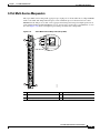
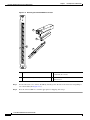
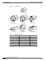
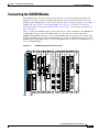
ESCON Aggregation Cards
The ESCON aggregation card is a 10-port card for ESCON (Enterprise Systems Connection) traffic. The
ESCON card converts the 10 client signals from optical to electrical and then aggregates them into a
single 2.5-Gbps signal. This aggregated signal is sent through the backplane and the active switch fabric
to either a 10-Gbps ITU trunk card or a 10-Gbps uplink card. The cross connection between the two cards
is configured using the CLI (command-line interface). The ESCON aggregation card has a redundant
backplane connection.
The ESCON aggregation card uses multimode 62.5/125 µm optical cable with SFPs (small form factor
pluggables) and MT-RJ connectors for the client signals. (See Figure 1-21.)
Cisco ONS 15530 Hardware Installation Guide
OL-7706-01
1-25
Chapter 1
Cisco ONS 15530 Overview
Cisco ONS 15530 Components
Note
A patch cable to adapt MT-RJ connectors to standard ESCON connectors directly or intermediately to
SC-type connectors may be required.
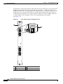
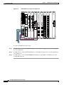
Figure 1-21
ESCON Aggregation Card
ST
AT
U
S
1
0
0
T
X
R
X
2
T
X
3
R
X
4
1
T
X
R
X
2
T
X
R
X
3
T
X
R
X
4
T
X
R
X
5
T
X
R
X
6
T
X
R
X
7
T
X
R
X
8
T
X
R
X
9
15530-LCMB-0200
R
X
77663
T
X
1
Card status LED
3
Port receive LED
2
Port transmit LED
4
Port number
This signal is sent through the switch fabric to a 10-Gbps ITU trunk card or a 10-Gbps uplink card. The
10-Gbps ITU trunk card converts the aggregated signal to an ITU-compliant wavelength, or channel. The
10-Gbps uplink card converts the aggregated signal to transmit to another shelf.
Cisco ONS 15530 Hardware Installation Guide
1-26
OL-7706-01
Chapter 1
Cisco ONS 15530 Overview
Cisco ONS 15530 Components
Table 1-12 describes the ESCON aggregation card LED status.
Table 1-12
ESCON Aggregation Card LEDs
LED
Status
Description
STATUS
Green
Card is properly initialized.
Blinking green Good system clock is present and card is out of
reset state.
Yellow
System clock is not present.
TX
Green
Port is up and transmit laser is enabled.
RX
Green
Light reception exists at the port.
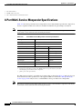
The ESCON aggregation card uses single-mode and multimode SFP optics for the client signals. There
are no restrictions on populating the line card with SFPs. For example, you can mix a single-mode SFP
optics with a multimode SFP optics on the same ESCON aggregation card. Table 1-13 lists the
characteristics for the SFP optics supported by the ESCON aggregation card.
Table 1-13
Note
ESCON Aggregation Card SFP Optics Characteristics
Wavelength
Connector
Type
Model Number
Clock Rate Range
Fiber Type
15500-XVRA-01A2
ESCON, OC-3/ STM-1 SR
MM 50/125 µm
1310 nm
MM 62.5/125 µm
MT-RJ
15500-XVRA-10A1
Low-band 8 Mbps to
200 Mbps
MM 50/125 µm
1310 nm
MM 62.5/125 µm
LC
15500-XVRA-10B1
Low-band 8 Mbps to
200 Mbps
SM 9/125 µm
1310 nm
LC
15500-XVRA-11A1
Mid-band 200 Mbps to
622 Mbps
MM 62.5/125 µm 1310 nm
LC
15500-XVRA-11B1
Mid-band 200 Mbps to
1.25 Gbps
SM 9/125 µm
1310 nm
LC
15500-XVRA-12B1
High-band 1.062 Gbps to
2.488 Gbps
SM 9/125 µm
1310 nm
LC
The SFP optics must be purchased separately. Protocol monitoring is the same as for single mode
transponder modules and multimode transponder modules.
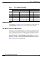
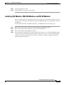
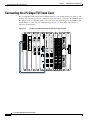
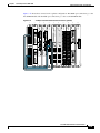
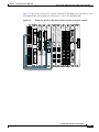
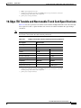
4-Port 1-Gbps/2-Gbps FC Aggregation Cards
The Cisco ONS 15530 supports a line card for FC (Fibre Channel), FICON, and ISC traffic. The 4-port
1-Gbps/2-Gbps FC aggregation card accepts up to four SFP (small form-factor pluggable) optics for
client traffic. Each SFP optic supports either FC, FICON, or ISC, depending on how it is configured in
the CLI. The 4-port 1-Gbps/2-Gbps FC aggregation card connects four 2.5-Gbps electric signals, or
portgroup interfaces, to the switch fabric. The client port data streams must be mapped to one of these
portgroup interfaces, using the CLI. Only two 1-Gbps client interfaces or one 2-Gbps client interface can
Cisco ONS 15530 Hardware Installation Guide
OL-7706-01
1-27
Chapter 1
Cisco ONS 15530 Overview
Cisco ONS 15530 Components
be mapped into a single portgroup interface.The signal on the portgroup interfaces connects through the
backplane and the switch fabric on the active CPU switch module to a 2.5-Gbps ITU trunk card, a
10-Gbps ITU trunk card, or a 10-Gbps uplink card, where the signal is converted to, and from, an ITU
channel. The cross connections between the two cards through the backplane and switch fabrics are
configured using the CLI. The 4-port 1-Gbps/2-Gbps FC aggregation card has redundant connections
over the backplane to the switch fabric on the active and standby CPU switch modules.
(See Figure 1-22).
Figure 1-22
4-Port 1-Gbps/2-Gbps FC Aggregation Card
ST
AT
U
S
1
0
T
X
R
X
T
X
0
2
T
X
3
R
X
4
1
R
X
T
X
2
R
X
T
X
R
X
3
105162
15530-FC-4P
1
Status LED
3
Rx LED
2
Tx LED
4
Port number
Cisco ONS 15530 Hardware Installation Guide
1-28
OL-7706-01
Chapter 1
Cisco ONS 15530 Overview
Cisco ONS 15530 Components
Table 1-14 lists the LEDs on the 4-port 1-Gbps/2-Gbps FC aggregation card, their default conditions,
and what the conditions indicate.
Table 1-14
4-Port 1-Gbps/2-Gbps FC Aggregation Card LEDs
LED
Status
Description
STATUS
Off
No power to the board.
Red
Card is in reset or the LRC is not configured.
Yellow
Card is out of reset.
Green
Card is properly initialized.
TX
Green
Port is up and transmit laser is enabled.
RX
Green
Light reception exists at the port.
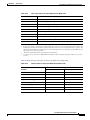
The 4-port 1-Gbps/2-Gbps FC aggregation card uses single-mode and multimode SFP optics for the
client signals. There are no restrictions on populating the line card with SFPs. Table 1-15 lists the
characteristics for the SFP optics supported by the 4-port 1-Gbps/2-Gbps FC aggregation card.
Table 1-15
4-port 1-Gbps/2-Gbps FC Aggregation Card SFP Optics Characteristics
Part Number
Protocols or Clock Rate
Range Supported
Fiber Type
Wavelength
Connector
Type
15500-XVRA-02C1
Gigabit Ethernet1, Fibre
Channel (1 Gbps)2, FICON
(1 Gbps), ISC-1 (1-Gbps)
MM 50/125 µm
850 nm
MM 62.5/125 µm
LC
15500-XVRA-03B1
Gigabit Ethernet3, Fibre
Channel (1 Gbps)4, FICON
(1 Gbps), ISC-3 links
compatibility mode
SM 9/125 µm
1310 nm
LC
15500-XVRA-03B2
Fibre Channel (1-Gbps and
2-Gbps), FICON (1-Gbps
and 2 Gbps)
SM 9/125 µm
1310 nm
LC
15500-XVRA-11B1
Mid-band variable rate
200-Mbps to 1.25-Gbps,
ISC-1
SM 9/125 µm
1310 nm
LC
15500-XVRA-12B1
High-band variable rate
1.062-Gbps to 2.488-Gbps,
ISC-1, ISC-3
SM 9/125 µm
1310 nm
LC
15454-SFP-GEFC-SX
MM 50/125 µm
850 nm
Fibre Channel (2-Gbps),
MM 62.5/125 µm
Fibre Channel (1-Gbps),
FICON (1-Gbps and 2 Gbps)
ISC-3 (1-Gbps and 2 Gbps)
LC
ONS-SE-GEFC-SX
MM 50/125 µm
850 nm
Fibre Channel (2-Gbps),
MM 62.5/125 µm
Fibre Channel (1-Gbps),
FICON (1-Gbps and 2 Gbps)
ISC-3 (1-Gbps and 2 Gbps)
LC
1. 1000BASE-SX
2. FC-0-100-M5-SN-S and FC-0-100-M6-SN-S standards
Cisco ONS 15530 Hardware Installation Guide
OL-7706-01
1-29
Chapter 1
Cisco ONS 15530 Overview
Cisco ONS 15530 Components
3. 1000BASE-LX
4. FC-0-100-SM-LC-S standard
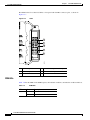
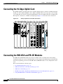
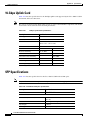
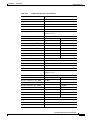
8-Port FC/GE Aggregation Cards
The Cisco ONS 15530 supports a line card specifically for ISC (compatibility and peer mode), FICON,
FC (Fibre Channel) and GE (Gigabit Ethernet) traffic. The 8-port Fibre Channel/Gigabit Ethernet
aggregation card accepts up to eight SFP (small form-factor pluggable) optics for client traffic. Each SFP
optic supports either FC or GE, depending on how it is configured in the CLI. The 8-port FC/GE
aggregation card converts client signals from two adjacent port pairs (0–1, 2–3, 4–5, or 6–7) from optical
form to electrical form, and then aggregates them into four 2.5-Gbps signals. These aggregated signals
pass through the backplane and the switch fabric on the active CPU switch module to a 2.5-Gbps ITU
trunk card, a 10-Gbps ITU trunk card, or a 10-Gbps uplink card. The cross connections between the two
cards through the backplane and switch fabric are configured using the CLI. The 8-port FC/GE
aggregation card has redundant connections over the backplane to the switch fabric on the active and
standby CPU switch modules. (See Figure 1-23).
Cisco ONS 15530 Hardware Installation Guide
1-30
OL-7706-01
Chapter 1
Cisco ONS 15530 Overview
Cisco ONS 15530 Components
Figure 1-23
8-Port FC/GE Aggregation Card
ST
AT
U
S
1
0
0
T
X
R
X
2
T
X
3
R
X
4
1
T
X
R
X
2
T
X
R
X
3
T
X
R
X
4
T
X
R
X
5
T
X
R
X
6
T
X
R
X
7
T
X
R
X
85440
15530FCGE-8P
1
Card status LED
3
Receive Port status
2
Transmit Port status
4
Port number
Note
The 8-port FC/GE aggregation card also supports FICON traffic at 1 Gbps.
Note
We strongly recommend configuring port pairs as ISC, FICON, FC only or GE only. Mixing FC,
FICON, and ISC with GE in a port pair increases the signal latency between nodes.
Cisco ONS 15530 Hardware Installation Guide
OL-7706-01
1-31
Chapter 1
Cisco ONS 15530 Overview
Cisco ONS 15530 Components
The Cisco ONS 15530 supports up to four 8-port FC/GE aggregation cards for a total of 32 client
signals.
Table 1-16 describes the LEDs on the 8-port FC/GE aggregation card.
Table 1-16
8-Port FC/GE Aggregation Card LEDs
LED
Status
Description
STATUS
Off
No power to the board.
Red
Card is in reset or the LRC is not configured.
Yellow
Card is out of reset.
Green
Card is properly initialized.
TX
Green
Port is up and transmit laser is enabled.
RX
Green
Light reception exists at the port.
The 8-port FC/GE aggregation card uses single-mode and multimode SFP optics for the client signals.
There are no restrictions on populating the line card with SFPs. For example, you can mix a single-mode
SFP optics with a multimode SFP optics on the same port pair. Table 1-17 lists the characteristics for the
SFP optics supported by the 8-port FC/GE aggregation card.
Table 1-17
Part Number
8-port FC/GE Aggregation Card SFP Optics Characteristics
Protocols or Clock Rate Range
Supported
Fiber Type
Wavelength
Connector
Type
15500-XVRA-02C1 Gigabit Ethernet1, Fibre Channel MM 50/125 µm
850 nm
(1 Gbps)2, FICON (1 Gbps)
MM 62.5/125 µm
LC
15500-XVRA-03B1 Gigabit Ethernet3, Fibre Channel SM 9/125 µm
(1 Gbps)4, FICON (1 Gbps),
ISC-3 links compatibility mode,
ISC peer mode
1310 nm
LC
15500-XVRA-11B1 Mid-band variable rate
200 Mbps to 1.25 Gbps
SM 9/125 µm
1310 nm
LC
15500-XVRA-11B2 Mid-band variable rate
200 Mbps to 1.25 Gbps
SM 9/125 µm
1310 nm
LC
15500-XVRA-12B1 High-band variable rate
1.062 Gbps to 2.488 Gbps
SM 9/125 µm
1310 nm
LC
1. 1000BASE-SX
2. FC-0-100-M5-SN-S and FC-0-100-M6-SN-S standards
3. 1000BASE-LX
4. FC-0-100-SM-LC-S standard
Note
The SFP optics must be purchased separately.
Protocol monitoring is the same as for single mode transponder modules and multimode transponder
modules.
Cisco ONS 15530 Hardware Installation Guide
1-32
OL-7706-01
Chapter 1
Cisco ONS 15530 Overview
Cisco ONS 15530 Components
8-Port Multi-Service Muxponders
The 8-port multi-service muxponder aggregates up to eight ports of client traffic into 2.5-Gbps DWDM
traffic to the trunk. The muxponder transports a mix of different protocols between sites in a metro
DWDM network. The protocols that can be aggregated and transported range from high-speed services
such as Fibre Channel and Gigabit Ethernet to low- speed services such as OC-3, Fast Ethernet, or even
T1 or E1. Figure 1-24 shows a nonsplitter protected 8-port multi-service muxponder.
8-Port Multi-Service Muxponder (Nonsplitter)
1
5
6
2
0
3
T
X
4
R
X
113755
Figure 1-24
1
Status LED
4
Port Rx (receive) LED
2
Port number
5
Trunk Tx (transmit) LED
3
Port Tx (transmit)
6
Trunk Rx (receive) LED
Cisco ONS 15530 Hardware Installation Guide
OL-7706-01
1-33
Chapter 1
Cisco ONS 15530 Overview
Cisco ONS 15530 Components
Figure 1-25 shows a splitter protected 8-port multi-service muxponder.
Figure 1-25
8-Port Multi-Service Muxponder (Splitter)
1
0
3
T
X
4
R
X
7
8
113754
5
2
1
Status LED
5
Trunk Tx (transmit) LED
2
Port number
6
Trunk Rx (receive) LED
3
Port Tx (transmit)
7
Trunk east LED
4
Port Rx (receive)
8
Trunk west LED
Table 1-18 lists the LEDs on the 8-port multi-service muxponder faceplate, their default conditions, and
what the conditions indicate.
Cisco ONS 15530 Hardware Installation Guide
1-34
OL-7706-01
Chapter 1
Cisco ONS 15530 Overview
Cisco ONS 15530 Components
Table 1-18
8-Port Multi-Service Muxponder LEDs
LED
Status
Description
Status
Off
No power to the muxponder.
Red
The functional image on the trunk is not configured.
Yellow
The system clock is not present.
Blinking green
The muxponder is out of reset, and the system clock is good
and waiting for software initialization.
Green
The muxponder is initialized and operational.
Rx green
Port is operational.
Rx off
Rx link is down.
Tx green
Transmit enabled.
Tx off
Transmit disabled.
East green
The muxponder is communicating with the West signal.
West green
The muxponder is communicating with the East signal.
Rx green
Light reception exists at the port.
Txgreen
Transmit enabled.
Client port status
Trunk status
The 8-port multi-service muxponder uses SFPs for the client signals. There are no restrictions on
populating the line card with SFPs. For example, you can mix a single-mode SFP with a multimode SFP
on the same card. Table 1-19 lists the characteristics for the SFPs supported by the 8-port multi-service
muxponder.
Table 1-19
8-Port Multi-Service Muxponder SFP Characteristics
Protocols or Clock Rate
Range Supported
Fiber Type
15500-XVRA-10A2
Low band 8 Mbps to
200 Mbps
MM 50/125 µm
1310 nm
MM 62.5/125 µm
LC
15500-XVRA-10B2
Low band 8 Mbps to
200 Mbps
SM 9/125 µm
1310 nm
LC
15500-XVRA-11A2
Mid-band 200 Mbps to
622 Mbps
MM 62.5/125 µm 1310 nm
LC
15500-XVRA-11B2
Mid-band 200 Mbps to
1.25 Gbps
SM 9/125 µm
1310 nm
LC
15500-XVRA-12B1
High-band 1.062 Gbps to
2.488 Gbps
SM 9/125 µm
1310 nm
LC
15454-SFP-GEFC-SX
Fibre Channel (2.125 Gbps), MM 50/125 µm
850 nm
Fibre Channel (1 Gbps),
MM 62.5/125 µm
Gigabit Ethernet
LC
15500-XVRA-08D1
T1 1 1.544 Mbps
Copper T1
–
RJ-45
15500-XVRA-09D1
E1 2.044 Mbps
Copper E1
–
RJ-45
Part Number
Wavelength
Connector
Type
Cisco ONS 15530 Hardware Installation Guide
OL-7706-01
1-35
Chapter 1
Cisco ONS 15530 Overview
Cisco ONS 15530 Components
Table 1-19
8-Port Multi-Service Muxponder SFP Characteristics (continued)
Part Number
Protocols or Clock Rate
Range Supported
15500-XVRA-10E12
15500-XVRA-11D1 4
Connector
Type
Fiber Type
Wavelength
SDI and DVB-ASI3 Video
Copper Digital
Video
–
Mini SMB
Coax
GE 1.25 Gbps, FE 1.25
Mbps
Copper GE/FE
–
RJ-45
1. DSX-1 interface
2. In a normal operating environment, the maximum digital video application connection length using a Belden 1694A cable
is 200 m (218 yd). If the chassis ambient operating temperature is above 45°C (113° F) and ports 0 and 1 are used for video
applications with this SFP, the maximum cable connection length supported may be less than the specified 200 m (218 yd),
depending on the operating environment.
3. Data Video Broadcast Asynchronous Serial Interface
4. To ensure proper operation of the 15500-XVRA-11D1 SFP, the ambient operating temperature should not exceed 45°C
(113°F).
The following warning applies to the copper SFPs listed in Table 1-19.
Warning
Note
For connections outside the building where the equipment is installed, the following ports must be
connected through an approved network termination unit with integral circuit protection.
15500-XVRA-08D1, 15500-XVRA-09D1, 15500-XVRA-10E1 and 15500-XVRA-11D1. Statement 1044
The SFPs must be purchased separately.
2.5-Gbps ITU Trunk Cards
The 2.5-Gbps ITU trunk card sends and receives the ITU grid wavelength signal to and from an OADM
module. This card accepts a 2.5-Gbps (3.125-Gbps line rate) electrical signal from either a 10-port
ESCON aggregation card or an 8-port FC/GE aggregation card, which is converted to the ITU grid
wavelength, or channel. The 2.5-Gbps ITU trunk card has redundant interfaces to the backplane,
connecting to the switch fabrics on the active and standby CPU switch modules. The ITU laser is tunable
to one of two channel frequencies. There are 16 different 2.5-Gbps ITU trunk cards (for channels 1–2,
3–4,..., 31–32) to support the 32 channels.
The 2.5-Gbps ITU trunk card has two versions: nonsplitter (shown in Figure 1-26) and splitter (shown
in Figure 1-27). The nonsplitter version has only one pair of optical connectors on the front panel, which
connects to either the east or the west OADM module, and can be used for unprotected, line card
protected, or switch fabric protected applications. The card supports 32 channels as shown in Table A-2
on page A-3.
Cisco ONS 15530 Hardware Installation Guide
1-36
OL-7706-01
Chapter 1
Cisco ONS 15530 Overview
Cisco ONS 15530 Components
Figure 1-26
U
AT
ST
3
S
1
2
2.5-Gbps ITU Trunk Card (Nonsplitter)
T
X
R
X
T
X
R
X
T
X
R
X
4
W ITU TX
W ITU RX
85315
E ITU TX
E ITU RX
1
Card status LED
3
Receive LED
2
Transmit LED
4
Transmit/Receive port
Cisco ONS 15530 Hardware Installation Guide
OL-7706-01
1-37
Chapter 1
Cisco ONS 15530 Overview
Cisco ONS 15530 Components
Figure 1-27
S
U
AT
ST
1
2
4
5
6
2.5-Gbps ITU Trunk Card (Splitter)
W
E
S
T
T
X
R
X
3
T
X
R
X
7
T
X
R
X
E
A
S
T
W ITU TX
W ITU RX
91504
E ITU TX
E ITU RX
1
Card status LED
5
Receive LED
2
West side port LED
6
East side port LED
3
West side port
7
East side port
4
Transmit LED
Cisco ONS 15530 Hardware Installation Guide
1-38
OL-7706-01
Chapter 1
Cisco ONS 15530 Overview
Cisco ONS 15530 Components
Table 1-20 lists and describes the 2.5-Gbps ITU Trunk Card LEDs.
Table 1-20
2.5-Gbps ITU Trunk Card LEDs
LED
Status
Description
STATUS
Green
Card is properly initialized.
WEST
Green
Card is listening to the west side signal.
TX
Green
Port is up and transmit laser is enabled.
RX
Green
Light reception exists at the port.
EAST
Green
Card is listening to the east side signal.
10-Gbps ITU Trunk Cards
The 10-Gbps ITU trunk card sends and receives the ITU grid wavelength signal to and from an OADM
module. This card accepts up to four 2.5-Gbps (3.125-Gbps line rate) electrical signals from the 10-port
ESCON aggregation cards and 8-port FC/GE aggregation cards, and combines them into one 10-Gbps
signal, which is converted to the ITU grid wavelength, or channel. The 10-Gbps ITU trunk card has four
separate redundant interfaces to the backplane, each connecting to the switch fabrics on the active and
standby CPU switch modules.
The 10-Gbps ITU trunk card has two versions: nonsplitter and splitter. The nonsplitter version has only
one pair of optical connectors on the front panel, which connects to either the east or the west OADM
module, and can be used for unprotected, line card protected, or switch fabric protected applications (see
Figure 1-28). The splitter version of the 10-Gbps ITU trunk card has two pairs of optical connectors on
the front panel, which connect to the east and west OADM modules, and is designed for splitter protected
applications (see Figure 1-29).
The Cisco ONS 15530 supports up to four 10-Gbps ITU trunk cards for a total of four channels.
Cisco ONS 15530 Hardware Installation Guide
OL-7706-01
1-39
Chapter 1
Cisco ONS 15530 Overview
Cisco ONS 15530 Components
Figure 1-28
10-Gbps ITU Trunk Card (Nonsplitter)
ST
AT
U
S
1
T
X
3
R
X
77661
4
2
R
X
T
X
1
Card status LED
3
Transmit LED
2
ITU port
4
Receive LED
Cisco ONS 15530 Hardware Installation Guide
1-40
OL-7706-01
Chapter 1
Cisco ONS 15530 Overview
Cisco ONS 15530 Components
Figure 1-29
10-Gbps ITU Trunk Card (Splitter)
ST
AT
U
S
1
2
4
5
6
W
E
S
T
T
X
T
X
3
R
X
R
X
E
A
S
T
T
X
7
R
X
W ITU TX
W ITU RX
77662
E ITU TX
E ITU RX
1
Card status LED
5
Receive LED
2
West side port LED
6
East side port LED
3
West side port
7
East side port
4
Transmit LED
Cisco ONS 15530 Hardware Installation Guide
OL-7706-01
1-41
Chapter 1
Cisco ONS 15530 Overview
Cisco ONS 15530 Components
Table 1-21 describes the10-Gbps ITU trunk card LED status.
Table 1-21
10-Gbps ITU Trunk Card LEDs
LED
Status
Description
STATUS
Green
Card is properly initialized.
WEST
Green
Card is listening to the west side signal.
TX
Green
Port is up and transmit laser is enabled.
RX
Green
Light reception exists at the port.
EAST
Green
Card is listening to the east side signal.
10-Gbps ITU Tunable Trunk Cards
The 10-Gbps ITU tunable trunk card works similar to the 10-Gbps ITU trunk card. The 10-Gbps ITU
tunable trunk card sends and receives the ITU grid wavelength signal to and from an OADM module.
This card accepts up to four 2.5-Gbps (3.125-Gbps line rate) electrical signals from the 10-port ESCON
aggregation cards and 8-port FC/GE aggregation cards, and combines them into one 10-Gbps signal,
which is converted to the ITU grid wavelength, or channel. The 10-Gbps ITU tunable trunk card has four
separate redundant interfaces to the backplane, each connecting to the switch fabrics on the active and
standby CPU switch modules.
The 10-Gbps ITU tunable trunk card has two versions: nonsplitter and splitter. The nonsplitter version
has only one pair of optical connectors on the front panel, which connects to either the east or the west
OADM module, and can be used for unprotected, line card protected, or switch fabric protected
applications (see Figure 1-30). The splitter version of the 10-Gbps ITU tunable trunk card has two pairs
of optical connectors on the front panel, which connect to the east and west OADM modules, and is
designed for splitter protected applications (see Figure 1-31).
The Cisco ONS 15530 supports up to four 10-Gbps ITU tunable trunk cards for a total of four channels.
The 10-Gbps ITU tunable trunk cards are equipped with Universal Transponders (UT1) with tuneable
lasers. The cards are programmable to four different frequencies belonging to one of the A, B, C, D, E,
F, G, or H bands. For more information on tunable frequencies, see Cisco ONS 15530 Planning Guide.
Cisco ONS 15530 Hardware Installation Guide
1-42
OL-7706-01
Chapter 1
Cisco ONS 15530 Overview
Cisco ONS 15530 Components
Figure 1-30
10-Gbps ITU Tunable Trunk Card (Nonsplitter)
ST
AT
U
S
1
T
X
3
R
X
77661
4
2
R
X
T
X
1
Card status LED
3
Transmit LED
2
ITU port
4
Receive LED
Cisco ONS 15530 Hardware Installation Guide
OL-7706-01
1-43
Chapter 1
Cisco ONS 15530 Overview
Cisco ONS 15530 Components
Figure 1-31
10-Gbps ITU Tunable Trunk Card (Splitter)
ST
AT
U
S
1
2
4
5
6
W
E
S
T
T
X
T
X
3
R
X
R
X
E
A
S
T
T
X
7
R
X
W ITU TX
W ITU RX
77662
E ITU TX
E ITU RX
1
Card status LED
5
Receive LED
2
West side port LED
6
East side port LED
3
West side port
7
East side port
4
Transmit LED
Cisco ONS 15530 Hardware Installation Guide
1-44
OL-7706-01
Chapter 1
Cisco ONS 15530 Overview
Cisco ONS 15530 Components
Table 1-22 describes the10-Gbps ITU tunable trunk card LED status.
Table 1-22
10-Gbps ITU Tunable Trunk Card LEDs
LED
Status
Description
STATUS
Green
Card is properly initialized.
WEST
Green
Card is listening to the west side signal.
TX
Green
Port is up and transmit laser is enabled.
RX
Green
Light reception exists at the port.
EAST
Green
Card is listening to the east side signal.
10-Gbps Uplink Cards
The 10-Gbps uplink card, shown in Figure 1-32, sends and receives a 10-GE 1310-nm signal to and from
a 10-GE uplink card on another Cisco ONS 15530, or to and from a 10-GE transponder module on a
Cisco ONS 15540 ESP or Cisco ONS 15540 ESPx. This card accepts up to four (3.125-Gbps line rate)
electrical signals from 10-port ESCON aggregation cards and 8-port FC/GE aggregation cards, and
combines them into one 10-GE signal.
The 10-Gbps uplink card has four separate redundant interfaces to the backplane. Each interface
connects to the switch fabric on the active and standby CPU switch modules.
The 10-Gbps uplink card has only one version: nonsplitter. The nonsplitter version has only one pair of
optical connectors on the front panel and can be used for unprotected or line card protected applications.
For splitter protected configurations, the splitter line card motherboards on the Cisco ONS 15540 ESP
and the Cisco ONS 15540 ESPx provide the facility protection.
The Cisco ONS 15530 supports up to four 10-Gbps uplink cards for a total of four signals.
Cisco ONS 15530 Hardware Installation Guide
OL-7706-01
1-45
Chapter 1
Cisco ONS 15530 Overview
Cisco ONS 15530 Components
Figure 1-32
10-Gbps Uplink Card
ST
AT
U
S
1
3
T
X
4
T
X
2
R
X
5
R
X
77665
15530-10GE-UPLINK
1
Card status LED
4
Receive LED
2
Transmit port
5
Receive port
3
Transmit LED
Table 1-23 describes the 10-Gbps uplink line card LED status.
Table 1-23
10-Gbps Uplink Line Card LEDs
LED
Status
Description
STATUS
Green
Card is properly initialized.
TX
Green
Port is up and transmit laser is enabled.
RX
Green
Light reception exists at the port.
Cisco ONS 15530 Hardware Installation Guide
1-46
OL-7706-01
C H A P T E R
2
Installing the Cisco ONS 15530
This chapter describes the installation procedures for the Cisco ONS 15530 chassis and its components.
This chapter includes the following sections:
•
Before Installing, page 2-1
•
Chassis-Lifting Guidelines, page 2-2
•
Rack-Mounting the Shelf, page 2-4
•
Grounding the Shelf, page 2-14
•
Installing and Removing Line Cards or Motherboards, page 2-17
•
Installing and Removing Modules, page 2-24
•
Replacing the Fan Assembly, page 2-27
•
Power Guidelines, page 2-29
•
Powering Up the Shelf, page 2-31
Note
Before you install, operate, or service the system, read the Regulatory Compliance and Safety
Information for the Cisco ONS 15500 Series for important safety information you should know before
working with the system.
Note
To ensure that your Cisco IOS software release supports your hardware, see the “New and Changed
Information” section on page vii. Also refer to the “Hardware Supported” section of the latest release
notes for the Cisco ONS 15530.
Before Installing
Before you install the Cisco ONS 15530, you must complete the following tasks:
•
Unpack and inspect the shelf.
•
Maintain a network record.
•
Assemble required tools and equipment.
•
Mount the shelf.
Cisco ONS 15530 Hardware Installation Guide
OL-7706-01
2-1
Chapter 2
Installing the Cisco ONS 15530
Chassis-Lifting Guidelines
Caution
Use extreme care when removing or installing connectors so you do not damage the connector housing
or scratch the end-face surface of the fiber. Always install protective covers on unused or disconnected
components to prevent contamination. Always clean fiber connectors before installing them.
Unpacking and Inspecting the Shelf
The Cisco ONS 15530 comes with the standard mounting set. The shelf is thoroughly inspected before
shipment. If any damage has occurred during transportation or if any item is missing, notify your Cisco
customer service representative immediately.
Upon receipt, inspect the equipment as follows:
Step 1
Take inventory.
Compare the equipment inside with the packing slip and the equipment list provided by customer
service. If there are any discrepancies, notify the Customer Service Center.
Step 2
Check for external damage.
Visually check all components and immediately report any shipping damage to your customer service
representative. Have the following information ready:
•
Invoice number of shipper (see packing slip)
•
Model and serial number of the damaged unit
•
Description of damage
•
Effect of damage on the installation
Keep a record of all of your hardware, configuration options, and network settings.
Mounting the Shelf
The unit is designed for rack-mounting in a cabinet rack. Use star-type lock washers on the rack screws
to ensure a good conductive connection between the chassis and the rack. For information about
installing the units in a customer cabinet, see the instructions from the cabinet manufacturer.
Chassis-Lifting Guidelines
The fully configured system weighs approximately 71 pounds. The chassis is not intended to be moved
frequently. Before you install the system, ensure that your site is properly prepared so you can avoid
having to move the chassis later to accommodate power sources and network connections.
Two or more people are required to lift the chassis. Each time you lift the chassis or any heavy object,
follow these guidelines:
•
Never attempt to lift the chassis by yourself. Because of the size and weight of the chassis, use at
least two people to safely lift and move it without causing injury or damaging the equipment.
•
Ensure that your footing is solid, and balance the weight of the chassis between your feet.
Cisco ONS 15530 Hardware Installation Guide
2-2
OL-7706-01
Chapter 2
Installing the Cisco ONS 15530
Chassis-Lifting Guidelines
•
Lift the chassis slowly; never move suddenly or twist your body as you lift.
•
Keep your back straight and lift with your legs, not your back. If you must bend down to lift the
chassis, bend at the knees, not at the waist, to reduce the strain on your back muscles.
•
Do not remove installed components from the chassis.
•
Always disconnect all external cables before lifting or moving the chassis.
To safely lift the chassis, follow these steps:
Warning
Two people are required to lift the chassis. To prevent injury, keep your back straight and lift with your
legs, not your back.
Step 1
Each person should stand on either side of the chassis, and place one hand under the air intake at the
bottom front of the chassis.
Step 2
With the other hand, grasp the handle on the chassis and carefully lift the chassis as shown in Figure 2-1
and Figure 2-2.
Figure 2-1
Lifting the Cisco ONS 15530 CHAS-E
TUS
STA
2
3
OFF
CON
T
X
R
X
T
X
R
X
0
T
X
R
X
1
T
X
R
X
2
3
5
T
X
R
X
4
T
X
R
X
5
6
FDX
BPS
100M
T
X
R
X
CON
CON
8
T
X
R
X
LINK
T
X
R
X
9
FDX
BPS
LINK
7
8
100M
T
X
R
X
6
T
X
R
X
6
T
X
R
X
7
T
X
R
X
7
T
X
R
X
8
T
X
R
X
8
AUX
T
X
R
X
9
0
T
X
R
X
1
T
X
R
X
T
X
R
X
E
A
S
T
2
3
9
T
X
R
X
4
T
X
W
E
S
T
T
X
R
X
T
X
R
X
5
T
X
R
X
T
X
6
T
X
R
X
7
T
X
R
X
8
T
X
R
X
FAIL
FASTENER
S MUST BE
FULLY ENGAGED
PRIOR
OPERATING
THE POWER TO
SUPPLY
GOOD
100-240V
8.0-3.5A
50-60HZ
9
15530-LCMB-0200
77694
T
X
R
X
15530-LCMB-0200
15530-LCMB-0200
15530-CPU
15530-CPU
15530-LCMB-0200
15530-LCMB-0200
AUX
9
T
X
R
X
R
X
T
X
R
X
R
X
4
HIST
CLR
5
T
X
R
X
T
X
R
X
CUT
OFF
7
T
X
R
X
TUS
4
A
L
A
R
M
S
ICAL
CIRTOR
MAJ
R
A
L
A
R
M
S
HIST
CLR
T
X
R
X
1
T
X
R
X
CUT
6
T
X
R
X
T
X
R
X
T
X
R
X
0
T
X
R
X
3
OFF
T
X
R
X
5
STA
T
PACH
COM
FLAS
T
X
R
X
T
X
R
X
2
CUT
T
X
R
X
TUS
IVE
T
X
R
X
MINO
R
X
TUS
ACT
T
X
R
X
ICAL
CIRTOR
MAJ
4
STA
STA
1
ET
0
T
X
R
X
RES
3
T
X
R
X
TUS
2
T
PACH
COM
FLAS
T
X
R
X
T
X
R
X
T
X
T
X
R
X
IVE
1
ACT
0
T
X
R
X
ET
T
X
R
X
RES
R
X
TUS
W
E
S
T T
X
STA
TUS
STA
R
X
TUS
E
A
S
T T
X
T R
X X
R
X
T
X
R
X
R
X
STA
T
X
TUS
T
X
STA
R
X
TUS
W
E
S
T T
X
STA
STA
T
X
T R
X X
R
X
Cisco ONS 15530 Hardware Installation Guide
OL-7706-01
2-3
Chapter 2
Installing the Cisco ONS 15530
Rack-Mounting the Shelf
Figure 2-2
Lifting the Cisco ONS 15530 CHAS-N
CON
CON
T
X
R
X
3
T
X
R
X
0
T
X
R
X
1
T
X
R
X
2
T
X
R
X
0
T
X
R
X
1
T
X
R
X
3
4
T
X
R
X
3
T
X
R
X
5
T
X
R
X
4
T
X
R
X
4
T
X
R
X
5
T
X
R
X
5
T
X
R
X
6
T
X
R
X
6
T
X
R
X
6
T
X
R
X
7
T
X
R
X
7
T
X
R
X
7
T
X
R
X
8
T
X
R
X
8
8
T
X
R
X
8
T
X
R
X
9
T
X
W
E
S
T
T
X
R
X
T
X
9
T
X
R
X
FAIL
FASTENER
S MUST BE
FULLY ENGAGED
PRIOR
OPERATING
THE POWER TO
SUPPLY
GOOD
100-240V
8.0-3.5A
50-60HZ
9
15530-LCMB-0200
77693
T
X
R
X
15530-LCMB-0200
15530-LCMB-0200
15530-CPU
15530-CPU
15530-LCMB-0200
15530-LCMB-0200
AUX
9
E
A
S
T
2
R
X
T
X
R
X
R
X
T
X
R
X
AUX
T
X
R
X
FDX
BPS
9
100M
LINK
FDX
BPS
LINK
100M
7
TUS
STA
CON
8
2
HIST
CLR
6
T
X
R
X
TUS
STA
A
L
A
R
M
S
OFF
CUT
5
T
X
R
X
T
X
R
X
TUS
STA
TUS
STA
A
L
A
R
M
S
4
HIST
CLR
7
1
T
X
R
X
OFF
CUT
6
T
X
R
X
T
X
R
X
T
X
R
X
0
T
X
R
X
3
OFF
CUT
5
T
X
R
X
T
X
R
X
T
X
R
X
T
X
R
X
2
ICAL
CIRTOR
MAJ
R
T
X
R
X
T
X
R
X
MINO
R
X
4
1
T
X
R
X
ICAL
CIRTOR
MAJ
R
X
T
X
R
X
0
T
X
R
X
T
PACH
COM
FLAS
3
T
X
T
X
R
X
T
PACH
COM
FLAS
T
X
R
X
T
X
2
IVE
ACT
1
T
X
R
X
IVE
0
T
X
R
X
ACT
T
X
R
X
ET
R
X
RES
R
X
W
E
S
T T
X
ET
RES
R
X
E
A
S
T T
X
T R
X X
R
X
TUS
STA
T
X
TUS
STA
T
X
TUS
STA
R
X
TUS
STA
W
E
S
T T
X
TUS
STA
TUS
STA
E
A
S
T T
X
T R
X X
R
X
Rack-Mounting the Shelf
Rack-mounting the shelf is the preferred method of installation for the Cisco ONS 15530. This section
gives general rack-mount installation guidelines and explains how to install the rack-mount and
cable-management brackets on the Cisco ONS 15530 for the following types of installations:
•
General Rack-Mount Installation Guidelines, page 2-5
•
Flush-Mounting the Cisco ONS 15530 CHAS-N in a 19-Inch Rack, page 2-5
•
Flush-Mounting the Cisco ONS 15530 CHAS-E in a 21-Inch Rack, page 2-7
Cisco ONS 15530 Hardware Installation Guide
2-4
OL-7706-01
Chapter 2
Installing the Cisco ONS 15530
Rack-Mounting the Shelf
General Rack-Mount Installation Guidelines
When planning your rack-mount installation, consider the following guidelines:
•
Allow a minimum of 11 rack units (17.7 inches or 45.0 cm) of vertical rack space for the
Cisco ONS 15530 CHAS-E chassis with the air ramp baffle. The Cisco ONS 15530 CHAS-N
chassis requires a minimum of 9 rack units (15.7 inches or 39.9 cm) of vertical rack space. Measure
the proposed rack location before mounting the chassis in the rack.
The Cisco ONS 15530 CHAS-E chassis cannot be installed in a 19-inch rack.
Note
•
Check for obstructions (such as a power strip) that could impair rack-mount installation before using
a particular rack. If a power strip does impair a rack-mount installation, remove the power strip
before installing the chassis, and then replace it after the chassis is installed.
•
Allow sufficient clearance around the rack for maintenance. If the rack is mobile, you can push it
back near a wall or cabinet for normal operation and pull it out for maintenance (installing or moving
line cards, connecting cables, or replacing or upgrading components). Otherwise, allow 19 inches
(48.3 cm) of clearance to remove FRUs (field replaceable units).
•
Maintain a minimum clearance of 3 inches (7.62 cm) on the front, top, and sides of the chassis for
the cooling air inlet and exhaust ports, respectively. Avoid placing the chassis in an overly congested
rack or directly next to another equipment rack; otherwise, the heated exhaust air from other
equipment can enter the inlet air vents and cause an over temperature condition inside the chassis.
Caution
To prevent chassis overheating, never install a Cisco ONS 15530 in an enclosed rack or room
that is not properly ventilated or air conditioned.
Caution
Always install the air ramp baffle below the Cisco ONS 15530 CHAS-E.
•
Always install heavier equipment in the lower half of a rack to maintain a low center of gravity to
prevent the rack from falling over.
•
Install and use the cable-management brackets included with the Cisco ONS 15530 to keep cables
organized and out of the way of the line cards and CPU switch modules. Ensure that cables from
other equipment already installed in the rack do not impair access to the line cards, or require you
to disconnect cables unnecessarily to perform equipment maintenance or upgrades.
•
Install rack stabilizers (if available) before you mount the chassis.
•
Provide an adequate chassis ground (earth) connection for your chassis.
Flush-Mounting the Cisco ONS 15530 CHAS-N in a 19-Inch Rack
The Cisco ONS 15530 CHAS-N can be flush-mounted in a 19-inch equipment rack using the
rack-mounting kit provided with your system. The rack-mounting kit contains the following parts:
•
Two mounting brackets and screws
•
Cable management brackets
•
Optional 23-inch rack-mount brackets
Cisco ONS 15530 Hardware Installation Guide
OL-7706-01
2-5
Chapter 2
Installing the Cisco ONS 15530
Rack-Mounting the Shelf
Note
Warning
The Cisco ONS 15530 CHAS-E chassis cannot be installed in a 19-inch rack.
At least three people are required to mount the chassis in the equipment rack: two people are needed
to hold the chassis in place while a third person tightens the mounting screws. When handling the
chassis, always follow proper lifting practices as outlined in the “Chassis-Lifting Guidelines” section
on page 2-2.
To flush-mount the Cisco ONS 15530 CHAS-N chassis in a 19-inch equipment rack, follow these steps :
Step 1
Attach the mounting brackets to the shelf (see Figure 2-3).
Step 2
Lift the shelf into position between the rack posts (requires two people).
Step 3
Align the mounting bracket holes with the rack post holes (see Figure 2-4) and attach the shelf to the
rack (performed by the third person).
Attaching Mounting Brackets to Shelf
US
3
T
X
R
X
4
ST
HI R
CL
FF
TO
T
X
R
X
T
X
R
X
1
2
T
X
2
3
T
X
3
E
A
S
T
T
X
T
X
R
X
R
X
W
E
S
T
T
X
R
X
4
T
X
R
X
5
0
T
X
4
5
R
X
6
T
X
R
X
5
6
FAIL
T
X
N
CO
R
X
T
X
R
X
7
T
X
R
X
7
T
X
R
X
8
T
X
R
X
8
6
FASTENERS
FULLY ENGA MUST BE
OPERATING GED PRIOR TO
THE POWE
R SUPPLY
GOOD
100-240V
8.0-3.5A
50-60HZ
T
X
8
R
X
7
9
T
X
R
X
9
9
15530-LCMB-0200
F
ST AN
AT
U
S
T
X
R
X
15530-FCGE-8P
15530-LCMB-0200
15530-CPU
15530-CPU
15530-LCMB-0200
15530-LCMB-0200
X
AU
T
X
R
X
T
X
R
X
T
X
T
X
R
X
X
S
FD
BP
0M
10
K
LIN
T
X
R
X
AT
CU
7
ST
FF
TO
6
T
X
R
X
9
T
X
R
X
T
X
R
X
T
X
R
X
X
S
FD
BP
0M
10
K
LIN
T
X
R
X
8
US
AT
ST
AL
IC
RT R
CI
JO
MA
R
NO
5
ST
HI R
CL
4
T
X
R
X
A
L
A
R
M
S
T
X
R
X
X
AU
T
X
R
X
T
X
R
X
N
CO
T
X
R
X
1
R
X
A
L
A
R
M
S
FF
TO
CU
7
0
T
X
R
X
CU
6
T
X
R
X
2
3
N
CO
T
X
R
X
T
X
R
X
R
X
MI
5
1
R
X
AL
IC
RT R
JO
T
X
R
X
0
T
X
R
X
T
X
R
X
MA
R
X
4
T
X
R
X
2
CI
R
X
T
X
R
X
T
X
R
X
US
AT
ST
3
T
X
1
T
X
R
X
US
AT
ST
T
X
0
T
X
R
X
T
ACH
MPAS
CO FL
T
X
R
X
2
T
X
R
X
E
TIV
AC
T
X
R
X
T
SE
RE
1
US
AT
ST
0
T
X
R
X
T
ACH
MPAS
CO FL
R
X
T
X
R
X
E
TIV
AC
R
X
W
E
S
T T
X
T
R
X
E
A
S
T T
X
T R
X X
R
X
SE
RE
T
X
US
AT
ST
T
X
US
AT
ST
R
X
US
AT
ST
W
E
S
T T
X
US
AT
ST
US
AT
ST
E
A
S
T T
X
T R
X X
R
X
77898
Figure 2-3
Cisco ONS 15530 Hardware Installation Guide
2-6
OL-7706-01
Chapter 2
Installing the Cisco ONS 15530
Rack-Mounting the Shelf
Figure 2-4
Attaching Shelf to Equipment Rack
AT
US
N
CO
T
X
R
X
0
T
X
R
X
1
T
X
R
X
2
3
4
T
X
R
X
4
T
X
R
X
5
T
X
R
X
5
T
X
R
X
6
T
X
R
X
6
E
A
S
T
2
T
X
R
X
3
T
X
R
X
4
T
X
R
X
5
T
X
R
X
T
X
W
E
S
T
T
X
R
X
T
X
FAIL
6
7
T
X
R
X
7
8
T
X
R
X
8
T
X
R
X
8
9
T
X
R
X
9
15530-LCMB-0200
15530-LCMB-0200
9
77899
F
ST AN
AT
U
S
T
X
R
X
FASTENERS
FULLY ENGA MUST BE
OPERATING GED PRIOR TO
THE POWE
R SUPPLY
GOOD
100-240V
8.0-3.5A
50-60HZ
7
15530-LCMB-0200
15530-CPU
15530-CPU
15530-LCMB-0200
15530-LCMB-0200
T
X
R
X
1
T
X
R
X
T
X
R
X
8
9
0
T
X
R
X
R
X
T
X
R
X
T
X
R
X
T
X
R
X
R
X
T
X
R
X
X
AU
T
X
R
X
3
X
AU
T
X
R
X
9
T
X
R
X
T
X
R
X
X
S
FD
BP
0M
10
K
LIN
N
CO
8
2
ST
HI R
CL
FF
TO
CU
7
X
S
FD
BP
0M
10
K
LIN
6
T
X
R
X
ST
FF
TO
CU
ST
HI R
CL
T
X
R
X
US
AT
ST
AL
IC
RT R
JO
MA
R
NO
CI
5
MI
T
X
R
X
FF
TO
7
T
X
R
X
4
A
L
A
R
M
S
N
CO
6
T
X
R
X
T
X
R
X
T
X
R
X
A
L
A
R
M
S
CU
5
T
X
R
X
1
3
AL
IC
RT R
JO
T
X
R
X
0
T
X
R
X
T
X
R
X
MA
R
X
4
T
X
R
X
2
CI
R
X
T
X
R
X
T
X
R
X
US
AT
ST
3
T
X
1
T
X
R
X
US
AT
ST
T
X
R
X
T
X
2
0
T
X
R
X
T
ACH
MPAS
CO FL
T
X
R
X
T
X
R
X
E
TIV
AC
1
T
SE
RE
0
T
X
R
X
US
AT
ST
R
X
T
X
R
X
T
ACH
MPAS
CO FL
R
X
W
E
S
T T
X
E
TIV
AC
R
X
E
A
S
T T
X
T R
X X
R
X
T
SE
RE
T
X
US
AT
ST
T
X
US
AT
ST
R
X
US
AT
ST
W
E
S
T T
X
US
AT
ST
US
AT
ST
E
A
S
T T
X
T R
X X
R
X
Step 4
Check that all release levers are in the closed position, the chassis mounting screws are tight, and all
CPU switch module and line card captive screws are tight.
Flush-Mounting the Cisco ONS 15530 CHAS-E in a 21-Inch Rack
The Cisco ONS 15530 CHAS-E can be flush-mounted in a 21-inch equipment rack using the
rack-mounting kit provided with your system. The rack-mounting kit contains the following parts:
Caution
•
Two mounting brackets and screws
•
Cable management brackets
At least three people are required to mount the chassis in the equipment rack: two people are needed to
hold the chassis in place while a third person tightens the mounting screws. When handling the chassis,
always follow proper lifting practices as outlined in the “Chassis-Lifting Guidelines” section on
page 2-2.
Cisco ONS 15530 Hardware Installation Guide
OL-7706-01
2-7
Chapter 2
Installing the Cisco ONS 15530
Rack-Mounting the Shelf
To flush-mount the Cisco ONS 15530 CHAS-N chassis in a 19-inch equipment rack, use the following
steps:
Step 1
Attach the mounting brackets to the shelf (see Figure 2-5).
Step 2
Lift the shelf into position between the rack posts (requires two people).
Step 3
Align the mounting bracket holes with the rack post holes (see Figure 2-6) and attach the shelf to the
rack (performed by the third person).
Figure 2-5
Attaching Mounting Brackets to Shelf
ST
US
AT
ST
US
AT
US
3
T
X
R
X
T
X
R
X
4
T
X
T
X
R
X
T
X
R
X
T
X
R
X
5
T
X
R
X
0
T
X
1
2
T
X
2
3
T
X
3
E
A
S
T
T
X
T
X
R
X
R
X
W
E
S
T
T
X
R
X
4
T
X
R
X
4
5
T
X
X
S
FD
BP
0M
10
K
LIN
T
X
R
X
R
X
6
T
X
R
X
T
X
R
X
7
T
X
R
X
7
T
X
R
X
8
T
X
R
X
8
5
6
FAIL
T
X
R
X
6
FASTENERS
FULLY ENGA MUST BE
OPERATING GED PRIOR TO
THE POWE
R SUPPLY
GOOD
N
CO
100-240V
8.0-3.5A
50-60HZ
T
X
8
R
X
X
AU
7
9
T
X
R
X
9
9
15530-LCMB-0200
91396
T
X
R
X
15530-FCGE-8P
15530-LCMB-0200
15530-CPU
15530-CPU
15530-LCMB-0200
15530-LCMB-0200
X
AU
T
X
R
X
AT
US
7
T
X
R
X
ST
AT
6
T
X
R
X
T
X
R
X
ST
HI R
CL
FF
TO
CU
T
X
R
X
9
1
R
X
FF
TO
CU
5
AL
IC
RT R
JO
MA
R
NO
T
X
R
X
CI
4
A
L
A
R
M
S
MI
T
X
R
X
8
0
T
X
R
X
R
X
A
L
A
R
M
S
N
CO
T
X
R
X
T
ACH
MPAS
CO FL
7
2
3
X
S
FD
BP
0M
10
K
LIN
6
T
X
R
X
T
X
R
X
R
X
N
CO
T
X
R
X
T
X
R
X
E
TIV
AC
5
1
R
X
ST
HI R
CL
T
X
R
X
0
T
X
R
X
T
X
R
X
AL
IC
RT R
JO
MA
R
X
T
X
R
X
2
CI
R
X
4
T
X
R
X
T
3
T
X
1
T
X
R
X
SE
RE
2
0
T
X
R
X
T
ACH
MPAS
CO FL
T
X
R
X
T
X
R
X
FF
TO
CU
R
X
ST
US
1
T
X
R
X
T
X
AT
0
T
X
R
X
E
TIV
AC
R
X
T
X
R
X
T
SE
RE
W
E
S
T T
X
ST
US
E
A
S
T T
X
T R
X X
R
X
T
X
R
X
R
X
AT
US
T
X
ST
T
X
AT
R
X
US
W
E
S
T T
X
ST
US
AT
AT
ST
ST
US
AT
ST
E
A
S
T T
X
T R
X X
R
X
Cisco ONS 15530 Hardware Installation Guide
2-8
OL-7706-01
Chapter 2
Installing the Cisco ONS 15530
Rack-Mounting the Shelf
Figure 2-6
Attaching Shelf to Equipment Rack
US
AT
T
X
R
X
T
X
R
X
4
CU
FF
ST
HI R
CL
TO
T
X
R
X
T
X
R
X
1
2
T
X
2
3
T
X
3
E
A
S
T
T
X
T
X
R
X
R
X
W
E
S
T
T
X
R
X
4
T
X
R
X
5
0
T
X
4
5
R
X
X
S
FD
BP
0M
10
K
LIN
T
X
R
X
6
T
X
R
X
7
T
X
R
X
7
T
X
R
X
8
T
X
R
X
8
T
X
R
X
FASTENERS
FULLY ENGA MUST BE
OPERATING GED PRIOR TO
THE POWE
R SUPPLY
GOOD
5
6
FAIL
T
X
R
X
6
100-240V
8.0-3.5A
50-60HZ
T
X
8
R
X
7
9
T
X
R
X
9
9
15530-LCMB-0200
91397
F
ST AN
AT
U
S
T
X
R
X
15530-FCGE-8P
15530-LCMB-0200
15530-CPU
15530-CPU
15530-LCMB-0200
15530-LCMB-0200
X
AU
T
X
R
X
T
X
T
X
N
CO
9
ST
FF
7
8
US
AT
ST
TO
CU
6
T
X
R
X
3
X
AU
T
X
R
X
T
X
R
X
T
X
R
X
1
R
X
T
X
R
X
T
X
R
X
N
CO
T
X
R
X
US
AT
ST
US
AT
ST
R
5
T
X
R
X
AL
IC
RT R
JO
T
X
R
X
NO
4
MA
T
X
R
X
A
L
A
R
M
S
X
S
FD
BP
0M
10
K
LIN
7
0
T
X
R
X
R
X
A
L
A
R
M
S
ST
HI R
CL
6
T
X
R
X
2
3
N
CO
T
X
R
X
T
X
R
X
R
X
CI
5
1
R
X
FF
TO
CU
R
X
0
T
X
R
X
T
X
R
X
MI
T
X
R
X
T
X
R
X
T
X
R
X
2
AL
4
T
X
R
X
IC
RT R
CI
JO
MA
R
X
T
X
R
X
1
T
ACH
MPAS
CO FL
3
T
X
0
T
X
R
X
E
TIV
AC
T
X
R
X
T
X
2
T
X
R
X
T
ACH
MPAS
CO FL
T
X
R
X
T
SE
RE
1
US
AT
ST
0
T
X
R
X
E
TIV
R
X
T
X
R
X
AC
R
X
W
E
S
T T
X
T
R
X
E
A
S
T T
X
T R
X X
R
X
SE
RE
T
X
US
AT
ST
T
X
US
AT
ST
R
X
US
AT
ST
W
E
S
T T
X
US
AT
ST
US
AT
ST
E
A
S
T T
X
T R
X X
R
X
Step 4
Check that all release levers are in the closed position, the chassis mounting screws are tight, and all
CPU switch module and line card captive screws are tight.
Step 5
Proceed to the “Attaching the Air Ramp Baffle” section on page 2-10.
Cisco ONS 15530 Hardware Installation Guide
OL-7706-01
2-9
Chapter 2
Installing the Cisco ONS 15530
Rack-Mounting the Shelf
Attaching the Air Ramp Baffle
The air ramp baffle redirects the intake of cooling air from directly below, to the front of the
Cisco ONS 15530 CHAS-E chassis, while deflecting hot exhaust air from equipment installed below.
To attach the air ramp baffle to the Cisco ONS 15530 CHAS-E chassis, follow these steps:
Step 1
Attach the mounting brackets to the air ramp baffle as shown in Figure 2-7.
Air Ramp Baffle Mounting Brackets
79553
Figure 2-7
Step 2
Position the air ramp baffle directly under the Cisco ONS 15530 CHAS-E chassis.
Step 3
Screw the air ramp baffle to the equipment rack as shown in Figure 2-8.
Cisco ONS 15530 Hardware Installation Guide
2-10
OL-7706-01
Chapter 2
Installing the Cisco ONS 15530
Rack-Mounting the Shelf
Figure 2-8
Installing the Air Ramp Baffle
7
T
X
T
X
R
X
T
X
R
X
4
T
X
R
X
T
X
R
X
1
2
T
X
2
3
T
X
3
E
A
S
T
T
X
T
X
R
X
R
X
W
E
S
T
T
X
R
X
4
T
X
R
X
5
0
T
X
4
5
T
X
R
X
X
S
FD
BP
0M
10
K
LIN
T
X
R
X
6
T
X
R
X
7
T
X
R
X
7
T
X
R
X
8
T
X
R
X
8
T
X
R
X
FASTENERS
FULLY ENGA MUST BE
OPERATING GED PRIOR TO
THE POWE
R SUPPLY
GOOD
5
6
FAIL
T
X
N
CO
R
X
6
100-240V
8.0-3.5A
50-60HZ
T
X
8
R
X
7
9
T
X
R
X
9
9
15530-LCMB-0200
79544
F
ST AN
AT
U
S
T
X
R
X
15530-FCGE-8P
15530-LCMB-0200
15530-CPU
15530-CPU
15530-LCMB-0200
15530-LCMB-0200
X
AU
T
X
R
X
3
X
AU
9
1
R
X
T
X
R
X
T
X
R
X
N
CO
8
T
X
R
X
US
6
T
X
R
X
AT
T
X
R
X
T
X
R
X
ST
HI R
CL
FF
TO
CU
5
FF
TO
CU
T
X
R
X
AL
IC
RT R
JO
MA
R
NO
7
T
X
R
X
4
X
S
FD
BP
0M
10
K
LIN
6
T
X
R
X
T
X
R
X
T
X
R
X
A
L
A
R
M
S
N
CO
T
X
R
X
0
T
X
R
X
R
X
A
L
A
R
M
S
CI
5
2
3
ST
HI R
CL
T
X
R
X
T
X
R
X
R
X
FF
TO
CU
R
X
4
T
X
R
X
1
R
X
MI
R
X
T
X
R
X
0
T
X
R
X
T
X
R
X
AL
IC
RT R
JO
MA
R
X
3
T
X
T
X
R
X
2
CI
R
X
T
X
R
X
T
X
T
X
R
X
ST
T
X
2
T
ACH
MPAS
CO FL
T
X
R
X
T
X
R
X
US
AT
ST
1
E
R
X
W
E
S
T T
X
T
ACH
MPAS
CO FL
W
E
S
T T
X
US
AT
ST
0
T
X
R
X
US
AT
ST
T
X
R
X
TIV
AC
1
T
SE
RE
0
T
X
R
X
E
TIV
AC
T
X
R
X
T
SE
RE
E
A
S
T T
X
T R
X X
R
X
US
AT
ST
US
AT
ST
US
AT
ST
US
AT
US
AT
ST
ST
US
AT
ST
E
A
S
T T
X
T R
X X
R
X
Cisco ONS 15530 Hardware Installation Guide
OL-7706-01
2-11
Chapter 2
Installing the Cisco ONS 15530
Rack-Mounting the Shelf
Installing the Fiber Routing Management System
The fiber routing management system contains two main components; the cable routing tray and the
cable routing drawer. The fiber routing tray is installed directly over the fan assembly, and the fiber
routing drawer is installed below the Cisco ONS 15530 chassis. (See Figure 2-9.)
Figure 2-9
Fiber Management System
T
X
R
X
T
X
R
X
T
X
R
X
X
AU
T
X
R
X
T
X
R
X
T
X
R
X
X
AU
T
X
R
X
T
X
R
X
T
X
R
X
85009
15530-LCMB-0200
15530-LCMB-0200
15530-LCMB-0200
15530-CPU
15530-CPU
15530-LCMB-0200
15530-LCMB-0200
T
X
R
X
Cisco ONS 15530 Hardware Installation Guide
2-12
OL-7706-01
Chapter 2
Installing the Cisco ONS 15530
Rack-Mounting the Shelf
Installing the Fiber Routing Tray
To install the fiber routing tray, follow these steps:
Step 1
Place the fiber routing tray (2) over the fan assembly, ensuring that the fan assembly can be accessed
when the fiber routing tray is locked (1 and 2) in the raised position. (See Figure 2-10.)
Figure 2-10
Raising the Fiber Routing Tray
T
X
R
X
3
T
X
R
X
T
X
R
X
T
X
R
X
X
AU
X
AU
T
X
R
X
T
X
R
X
T
X
R
X
T
X
R
X
3
15530-LCMB-0200
2
15530-LCMB-0200
15530-LCMB-0200
15530-CPU
15530-CPU
15530-LCMB-0200
15530-LCMB-0200
2
T
X
R
X
T
X
R
X
1
2
1
85011
2
1
Hook
2
Flip up
3
Latch
Step 2
Secure the fiber routing tray to the rack with four 12-24 screws, two on each side.
Step 3
Hold the fiber routing drawer with both hands and position it in the rack beneath the chassis.
(See Figure 2-9.)
Step 4
Align the mounting holes on the bracket with the mounting holes in the equipment rack.
Step 5
Install the 12-24 or 10-32 screws through the elongated holes in the brackets and into the threaded holes
in the mounting post. Repeat this step for the other side.
Cisco ONS 15530 Hardware Installation Guide
OL-7706-01
2-13
Chapter 2
Installing the Cisco ONS 15530
Grounding the Shelf
Installing the Fiber Routing Drawer
To install the fiber routing drawer, follow these steps:
Step 1
Hold the drawer with both hands and position the drawer in the rack beneath the chassis.
(See Figure 2-9.)
Step 2
Align the mounting holes on the bracket with the mounting holes in the equipment rack.
Step 3
Install the 12-24 or 10-32 screws through the elongated holes in the brackets and into the threaded holes
in the mounting post. Repeat this step for the other side.
Grounding the Shelf
Two system (earth) grounding holes are provided under the power supplies at the bottom right of the
shelf.
Shelf Grounding Guidelines
To make an adequate grounding connection, you need the following parts and tools:
Note
•
Grounding lug.
•
Two M4 (metric) hex-head screws with locking washers.
•
One grounding wire (6 AWG recommended).
•
Number 2 Philips head screwdriver.
•
Crimping tool. This tool must be large enough to accommodate the girth of the grounding lug when
you crimp the grounding cable into the lug.
•
Wire-stripping tool.
The grounding lug and M4 screws are included in your accessory kit that ships with the system.
Shelf Grounding Procedures
This section describes how to connect the Cisco ONS 15530 to earth ground. You must complete this
procedure before connecting system power or powering up your shelf.
Cisco ONS 15530 Hardware Installation Guide
2-14
OL-7706-01
Chapter 2
Installing the Cisco ONS 15530
Grounding the Shelf
To ground the shelf, follow these steps:
Step 1
Use a wire-stripping tool to remove approximately 0.75 inch (20 mm) of the covering from the end of
the grounding wire (see Figure 2-11).
Figure 2-11
Attaching the Grounding Wire to Grounding Lug
30020
0.75 in.
(2 cm)
Wire
Grounding lug
Step 2
Insert the stripped end of the grounding wire into the open end of the grounding lug (see Figure 2-11).
Step 3
Use the crimping tool to secure the grounding wire in place in the grounding lug.
Step 4
Locate the grounding receptacles on the chassis (see Figure 2-12).
Figure 2-12
T
X
R
X
T
X
R
X
X
S
FD
BP
0M
10
K
LIN
X
S
FD
BP
0M
K
LIN
0
T
X
R
X
1
T
X
R
X
2
0
T
X
R
X
1
T
X
R
X
E
A
S
T
2
T
X
R
X
3
T
X
R
X
5
6
T
X
R
X
4
3
T
X
R
X
5
T
X
R
X
6
T
X
R
X
4
T
X
R
X
5
T
X
R
X
W
E
S
T
T
X
R
X
T
X
FAIL
6
T
X
R
X
7
T
X
R
X
7
8
T
X
R
X
8
T
X
R
X
8
9
T
X
R
X
X
AU
9
15530-LCMB-0200
F
ST AN
AT
U
S
T
X
R
X
15530-LCMB-0200
15530-LCMB-0200
15530-CPU
15530-CPU
15530-LCMB-0200
15530-LCMB-0200
7
T
X
R
X
9
FASTENERS
FULLY ENGA MUST BE
OPERATING GED PRIOR TO
THE POWE
R SUPPLY
GOOD
100-240V
8.0-3.5A
50-60HZ
T
X
R
X
T
X
R
X
T
X
R
X
8
9
T
X
R
X
R
X
4
X
AU
T
X
R
X
N
CO
N
CO
T
X
R
X
9
3
T
X
R
X
77692
7
8
2
ST
HI R
CL
FF
TO
CU
6
T
X
R
X
T
X
R
X
T
X
R
X
10
7
T
X
R
X
US
AT
AL
IC
RT R
JO
MA
R
NO
ST
HI R
CL
FF
TO
6
T
X
R
X
T
X
R
X
5
N
CO
T
X
R
X
T
X
R
X
4
T
X
R
X
A
L
A
R
M
S
CI
5
T
X
R
X
CU
T
X
R
X
1
T
X
R
X
A
L
A
R
M
S
FF
TO
CU
R
X
4
0
T
X
R
X
3
MI
R
X
T
X
R
X
T
X
R
X
T
X
R
X
2
AL
IC
RT R
JO
MA
R
X
3
T
X
T
X
R
X
CI
R
X
T
X
R
X
T
X
2
T
ACH
MPAS
CO FL
T
X
T
X
R
X
ST
E
T
X
R
X
US
AT
ST
1
TIV
AC
R
X
W
E
S
T T
X
T
ACH
MPAS
CO FL
W
E
S
T T
X
US
AT
ST
0
T
X
R
X
US
AT
ST
T
X
R
X
T
SE
1
RE
0
T
X
R
X
E
TIV
AC
T
X
R
X
T
SE
RE
E
A
S
T T
X
T R
X X
R
X
US
AT
ST
US
AT
ST
US
AT
ST
US
AT
ST
US
AT
ST
US
AT
ST
E
A
S
T T
X
T R
X X
R
X
Cisco ONS 15530 ESD Sockets
ESD sockets
Grounding
receptacle
Step 5
Place the grounding lug against the grounding receptacle at the bottom right of the chassis (see
Figure 2-13).
Cisco ONS 15530 Hardware Installation Guide
OL-7706-01
2-15
Chapter 2
Installing the Cisco ONS 15530
Grounding the Shelf
Installing the Grounding Lug
FF
7
T
X
R
X
X
S
FD
BP
0M
10
K
LIN
T
X
R
X
T
X
R
X
T
X
R
X
0
T
X
R
X
1
T
X
R
X
2
T
X
R
X
3
5
6
T
X
R
X
4
T
X
R
X
5
T
X
R
X
6
1
T
X
R
X
E
A
S
T
2
T
X
R
X
3
T
X
R
X
4
T
X
R
X
5
T
X
R
X
T
X
W
E
S
T
T
X
R
X
T
X
FAIL
6
7
7
T
X
R
X
7
8
T
X
R
X
8
T
X
R
X
8
9
T
X
R
X
9
15530-LCMB-0200
F
ST AN
AT
U
S
15530-LCMB-0200
15530-LCMB-0200
15530-CPU
15530-CPU
15530-LCMB-0200
9
T
X
R
X
FASTENERS
FULLY ENGA MUST BE
OPERATING GED PRIOR TO
THE POWE
R SUPPLY
GOOD
100-240V
8.0-3.5A
50-60HZ
T
X
R
X
X
AU
15530-LCMB-0200
T
X
R
X
0
T
X
R
X
R
X
4
8
9
T
X
R
X
R
X
X
T
X
R
X
3
AU
T
X
R
X
9
T
X
R
X
N
CO
N
CO
8
2
ST
HI R
CL
TO
CU
6
T
X
R
X
T
X
R
X
T
X
R
X
X
S
FD
BP
0M
10
K
LIN
T
X
R
X
US
AT
FF
TO
CU
7
ST
US
AT
ST
US
AT
ST
US
AT
ST
AL
IC
RT R
JO
MA
R
NO
CI
5
MI
4
T
X
R
X
A
L
A
R
M
S
N
6
T
X
R
X
T
X
R
X
T
X
R
X
A
L
A
R
M
S
CO
T
X
R
X
T
X
R
X
T
ACH
MPAS
CO FL
5
1
T
X
R
X
ST
HI R
CL
T
X
R
X
0
T
X
R
X
3
AL
R
X
4
T
X
R
X
T
X
R
X
2
IC
RT R
CI
JO
MA
R
X
T
X
R
X
1
T
X
R
X
E
TIV
AC
T
X
0
T
X
R
X
T
SE
3
RE
2
T
X
R
X
T
ACH
MPAS
CO FL
T
X
R
X
T
X
R
X
T
X
US
AT
ST
1
E
TIV
AC
0
T
X
R
X
T
R
X
T
X
R
X
FF
TO
CU
R
X
W
E
S
T T
X
SE
R
X
E
A
S
T T
X
T R
X X
R
X
RE
T
X
US
AT
ST
T
X
US
AT
ST
R
X
US
AT
ST
W
E
S
T T
X
US
AT
ST
US
AT
ST
E
A
S
T T
X
T R
X X
R
X
79144
Figure 2-13
Wire
Grounding lug
Grounding holes
Screws
Locking
washers
Step 6
Insert two screws through the holes in the grounding lug and the grounding receptacle. Ensure that the
grounding lug does not interfere with other hardware or rack equipment.
Step 7
Install the locking washers and nuts; tighten them to secure the grounding lug to the grounding
receptacle.
Step 8
Prepare the other end of the grounding wire and connect it to an appropriate grounding point in your site
to ensure adequate earth ground for the Cisco ONS 15530.
Note
The Grounding lug shown in Figure 2-13 should be positioned at a 45 degree angle to allow room for
cables.
Cisco ONS 15530 Hardware Installation Guide
2-16
OL-7706-01
Chapter 2
Installing the Cisco ONS 15530
Installing and Removing Line Cards or Motherboards
Preventing ESD Damage
Electrostatic discharge (ESD) damage occurs when electronic cards or components are mishandled and
can result in complete or intermittent failures. Note the following guidelines before you install or service
the system:
Note
•
Always wear an ESD-preventive wrist or ankle strap when handling electronic components. Connect
one end of the strap to an ESD jack or an unpainted metal component on the system (such as a
captive installation screw).
•
Handle cards by the faceplates and edges only; avoid touching the printed circuit board and
connector pins.
•
Place any removed component on an antistatic surface or in a static shielding bag.
•
Avoid contact between the cards and clothing. The wrist strap only protects the card from ESD
voltages on the body; ESD voltages on clothing can still cause damage.
For safety, periodically check the resistance value of the antistatic strap. The measurement should be
between 1 and 10 megohms (Mohms).
Installing and Removing Line Cards or Motherboards
The line cards and modules used on the Cisco ONS 15530 are hot-swappable. This section describes the
procedures for installing and removing the following line cards and motherboards from the chassis:
•
ESCON aggregation cards
•
4-port 1-Gbps/2-Gbps FC aggregation cards
•
8-port FC/GE aggregation cards
•
8-port multi-service muxponders
•
2.5-Gbps ITU trunk cards
•
10-Gbps ITU trunk cards
•
10-Gbps ITU tunable trunk cards
•
10-Gbps uplink cards
•
Transponder line cards
•
Carrier motherboards
•
CPU switch modules
Installing Line Cards or Motherboards
To install a line card or motherboard, follow these steps:
Step 1
Take the new line card or motherboard from the shipping container.
Step 2
Insert the line card or motherboard carefully into the chassis slot while guiding the upper and lower
edges line card or of the motherboard in the tracks until its connectors come into contact with the
backplane.
Cisco ONS 15530 Hardware Installation Guide
OL-7706-01
2-17
Chapter 2
Installing the Cisco ONS 15530
Installing and Removing Line Cards or Motherboards
Step 3
Use the release levers to push the line card or motherboard or processor card in until it is fully seated in
the backplane connector.
Step 4
Push the release levers in simultaneously to lock the line card or motherboard into the slot.
Step 5
Use a number 1 Philips screwdriver to tighten the captive installation screws.
Step 6
Check the LED to ensure proper installation while powered.
Removing Line Cards or Motherboards
To remove a line card or motherboard, follow these steps:
Step 1
Remove all cables from the line card or motherboard.
Step 2
Install appropriate dust covers on the fiber cable connectors and the blind plugs into the connectors on
the motherboard.
Step 3
Use a number 1 Philips screwdriver to loosen the captive installation screws.
Step 4
Pull the release levers out to release the line card or motherboard from the slot in the chassis.
Step 5
Use the release levers to pull the line card or motherboard out of the chassis.
Step 6
Place the removed line cards in a container appropriate for shipping and storage.
Installing SFPs into Aggregation Cards and Muxponders
To install SFPs into the ESCON aggregation cards, 8-port FC/GE aggregation cards, and 8-port
multi-service muxponders, follow these steps:
Step 1
Take the desired SFP from the shipping container.
Step 2
Install the SFP by inserting it in the aggregation card or muxponder.
Step 3
Push the SFP until you hear a click. The click indicates that it is securely set in the module.
Installing SFP with Mini SMB Coax Connectors
To install the 15500-XVRA-10E1SFP with mini SMB coax connectors into the 8-port multi-service
muxponder, follow these steps:
Step 1
Take the desired SFP from the shipping container.
Step 2
Install the mini SMB coax connector into the SFP by pushing the cable into the SFP. (See Figure 2-14.)
Note
If you are installing the 15500-XVRA-10E1, you must attach the cable to the SFP before
installing the SFP into the 8-port multi-service muxponder.
Cisco ONS 15530 Hardware Installation Guide
2-18
OL-7706-01
Chapter 2
Installing the Cisco ONS 15530
Installing and Removing Line Cards or Motherboards
Installing the 15500-XVRA-10E1 SFP
113974
Figure 2-14
Step 3
Twist the cable to secure it in the SFP.
Step 4
Install the SFP by inserting it in the muxponder.
Tip
In an unlikely event of the pull-tab is damaged or missing, use a screwdriver to push on the hinge pin to
unlock the SFP cage latch and pull the SFP out from SFP port
Removing SFP from Aggregation Cards and Muxponders
The SFPs used on the aggregation cards and muxponders have different types of connectors. The
different connector types on the SFP optics are:
•
RJ-45 connector (for 8-port multi-service muxponders)
•
MT-RJ connector (for ESCON aggregation cards)
•
LC connector (for 8-port FC/GE aggregation cards)
•
Mini SMB coax connector (for 8-port multi-service muxponders)
Each connector requires a different method of removal.
Note
Use the show hardware command to see what SFP you have currently installed in your module.
Removing Pull Tab SFPs with RJ-45 Connectors
To remove an SFP with an RJ-45 connector from the muxponder, follow these steps:
Step 1
Remove the cable from the desired SFP.
Step 2
Use the thumb on your left hand to push against the RJ-45 connector.
Step 3
Use your right hand to pull the pull tab on the SFP.
Step 4
Rotate the SFP while simultaneously pushing against the connector and pulling the pull tab. This releases
the SFP from the latch lock of the cage. (See Figure 2-15.)
Cisco ONS 15530 Hardware Installation Guide
OL-7706-01
2-19
Chapter 2
Installing the Cisco ONS 15530
Installing and Removing Line Cards or Motherboards
Releasing the SFP
120369
Figure 2-15
Step 5
Pull the SFP out and place it in a container appropriate for shipping and storage. (See Figure 2-16.)
Removing the SFP
120370
Figure 2-16
Tip
In an unlikely event of the pull-tab is damaged or missing, use a screwdriver to push on the hinge pin to
unlock the SFP cage latch and pull the SFP out from SFP port
Note
SFPs with RJ-45 connectors require cabling after it is installed, and removal of cables is required before
removing the SFP from the card.
Removing Non-Pull Tab SFPs with RJ-45 Connectors
To remove an SFP with an RJ-45 connector from the muxponder, follow these steps:
Step 1
Remove the cable from the desired SFP.
Step 2
Pull the latch on the SFP out. This releases the SFP from the latch lock of the cage.
Step 3
Pull the SFP out and place it in a container appropriate for shipping and storage.
Cisco ONS 15530 Hardware Installation Guide
2-20
OL-7706-01
Chapter 2
Installing the Cisco ONS 15530
Installing and Removing Line Cards or Motherboards
Note
SFPs with RJ-45 connectors require cabling after it is installed, and removal of cables is required before
removing the SFP from the card.
Removing SFP Optics with MT-RJ Connectors
Note
You need the SFP extraction and cable installation and removal tool to remove the SFP with the MT-RJ
connector.
To remove an SFP with an MT-RJ connector from the ESCON aggregation card, follow these steps:
Step 1
Remove the cable from the desired SFP.
Step 2
Remove the SFP from the module by pushing against the lever on the SFP to release it from the module.
(See Figure 2-17.)
Cisco ONS 15530 Hardware Installation Guide
OL-7706-01
2-21
Chapter 2
Installing the Cisco ONS 15530
Installing and Removing Line Cards or Motherboards
Figure 2-17 Removing the SFP with MT-RJ Connector
S
TA
S
TU
T
X
0
R
X
T
X
1
2
R
X
T
X
2
R
X
T
X
3
3
R
X
T
X
2
4
R
X
T
X
5
1
R
X
T
X
4
6
R
X
T
X
7
R
X
T
X
8
R
X
9
15530-LCMB-0200
R
X
94102
T
X
1
SFP placement in the module
3
Hole where the SFP extraction end of the tool
is inserted (two views)
2
Lever on the SFP (two views)
4
SFP extraction and cable installation and
removal tool
Step 3
Use the extraction tool to remove the SFP by inserting it into the side of the transceiver and pulling it
out of the module.(See Figure 2-17.)
Step 4
Place the removed SFP in a container appropriate for shipping and storage.
Cisco ONS 15530 Hardware Installation Guide
2-22
OL-7706-01
Chapter 2
Installing the Cisco ONS 15530
Installing and Removing Line Cards or Motherboards
Removing SFP Optics with LC Connectors
To remove an SFP with an LC connector from the 8-port FC/GE aggregation card, follow these steps:
Step 1
Remove the cable from the desired SFP.
Step 2
Remove the SFP from the module by pulling the latch on top of the SFP to release it from the module.
(See Figure 2-18.)
Figure 2-18 Removing the Transceiver with the LC Connector
ST
AT
U
S
0
T
X
R
X
1
T
X
R
X
2
T
X
R
X
3
T
X
R
X
4
T
X
1
R
X
5
T
X
R
X
6
T
X
R
X
7
2
T
X
R
X
94103
15530FCGE-8P
1
Release the latch.
2
Pull out the SFP optics.
Step 3
Continue to pull the latch down and use the latch to pull the SFP out of the module. (See Figure 2-18.)
Step 4
Place the removed SFP in a container appropriate for shipping and storage.
Cisco ONS 15530 Hardware Installation Guide
OL-7706-01
2-23
Chapter 2
Installing the Cisco ONS 15530
Installing and Removing Modules
Removing SFPs with Mini SMB Coax Connectors
To remove the 15500-XVRA-10E1 SFP with mini SMB coax connectors(MINISMB/BNC=) from the
8-port multi-service muxponder, follow these steps:
Step 1
Use the thumb on your left hand to push against the SFP.
Step 2
Use your right hand to pull the pull tab on the SFP.
Step 3
Twist the SFP slightly to unlock it from the latch lock of the cage.
Step 4
Remove the desired SFP from the 8-port multi-service muxponder.
Note
If you are removing the 15500-XVRA-10E1, you must remove the SFP from the muxponder
before detaching the cable.
Step 5
Twist the connector to loosen the cable.
Step 6
Pull the connector from the SFP.
Step 7
Place the removed SFP in a container appropriate for shipping and storage.
Installing and Removing Modules
The modules used on the Cisco ONS 15530 are hot-swappable. This section describes the procedures for
installing and removing the OADM (optical add drop multiplexing) module, the PSM (protection switch
modules), the OSC (optical supervisory channel) module, the WB-VOA (wide-band variable optical
attenuator) module, and the PB-OE (per-band power equalizer) module.
Warning
During this procedure, wear grounding wrist straps to avoid ESD damage to the card. Do not directly
touch the backplane with your hand or any metal tool, or you could shock yourself.
Installing OADM Modules and PSMs
Slot 0 of the Cisco ONS 15530 chassis holds half height OADM modules and PSMs.
To install an OADM module or PSM, follow these steps:
Step 1
Remove the module or the filler module from slot 0 of the Cisco ONS 15530 chassis.
Step 2
Take a new module from the shipping container.
Step 3
Insert the module carefully into slot 0 of the Cisco ONS 15530 chassis while guiding the upper and lower
edges of the module in the tracks until its connectors come into contact with the backplane connectors.
Place the module locking lever in place, and then use a number 1 Philips screwdriver to tighten the
module locking lever.
Cisco ONS 15530 Hardware Installation Guide
2-24
OL-7706-01
Chapter 2
Installing the Cisco ONS 15530
Installing and Removing Modules
Step 4
Attach the appropriate cables.
Step 5
Check the LEDs to ensure proper installation.
Installing OSC Modules, WB-VOA Modules, and PB-OE Modules
Up to two OSC modules can be installed in the carrier motherboard, one module for the west direction
and one for the east direction. The WB-VOA module and PB-OE module are also installed in the carrier
motherboard.
To install the OSC module, the WB-VOA module, or the PB-OE module, follow these steps:
Step 1
Disconnect all optical fiber connections from the WB-VOA and PB-OE modules.
Step 2
Remove the module or the filler module from the carrier motherboard.
Step 3
Take a new module from the shipping container.
Step 4
Insert the module carefully into the carrier motherboard (see Figure 2-19) slot while guiding the upper
and lower edges of the module in the tracks until its connectors come into contact with the backplane
connectors. Place the module locking lever in place, and then use a number 1 Philips screwdriver to
tighten the module locking lever.
Cisco ONS 15530 Hardware Installation Guide
OL-7706-01
2-25
Chapter 2
Installing the Cisco ONS 15530
Installing and Removing Modules
Figure 2-19
Module Insertion in Carrier Motherboard
2
1
1 P
M
15500-PEQ-02EF
2 S
TA
IN
79007
PM
OUT
UPG IN
UPG OUT
2
1
Module
2
Module locking lever
Step 5
Attach the appropriate cables.
Step 6
Check the LEDs to ensure proper installation.
Save the filler modules with the packaging material.
Removing Modules
Warning
High-performance devices on this card can get hot during operation. To remove the card, hold it by
the faceplate and bottom edge. Allow the card to cool before touching any other part of it or before
placing it in an antistatic bag.
Warning
Invisible laser radiation may be emitted from disconnected fibers or connectors. Do not stare into
beams or view directly with optical instruments.
Cisco ONS 15530 Hardware Installation Guide
2-26
OL-7706-01
Chapter 2
Installing the Cisco ONS 15530
Replacing the Fan Assembly
To remove a module from the Cisco ONS 15530 without interrupting system operation, follow these
steps:
Step 1
Remove all cables from the desired module.
Step 2
Use a number 1 Philips screwdriver to loosen the module locking lever (see Figure 2-19).
Step 3
Remove the module by carefully pulling it out of its slot.
Step 4
Reinstall the blank filler module.
Step 5
Place the removed module in a container appropriate for shipping and storage.
Replacing the Fan Assembly
To replace the fan assembly in the Cisco ONS 15530, follow these steps:
Step 1
Open and pull out the cable storage drawer installed immediately beneath the chassis that holds the
system fiber optic cables.
Step 2
Lock the drawer by pushing the lever down at the back left side of the drawer. (See Figure 2-20.)
Drawer Lock
79727
Figure 2-20
Cisco ONS 15530 Hardware Installation Guide
OL-7706-01
2-27
Chapter 2
Installing the Cisco ONS 15530
Replacing the Fan Assembly
Step 3
Untwist the black fasteners in the drawers to loosen the cable guide spools. (See Figure 2-21)
Figure 2-21
Loosening the Cables
2
2
1
79526
1
1
Fasteners
2
Spools
Step 4
Push the spools down towards the black fasteners. Carefully pull out the cables from the spools towards
the outside of the drawers. (See Figure 2-21.)
Step 5
Flip the cable management tray up so that it no longer covers the fan tray. (See Figure 2-22.)
Figure 2-22
Hooking the Cable Management Tray
T
X
R
X
3
T
X
R
X
T
X
R
X
T
X
R
X
T
X
R
X
X
AU
X
AU
T
X
R
X
T
X
R
X
T
X
R
X
15530-LCMB-0200
15530-LCMB-0200
2
15530-LCMB-0200
15530-CPU
15530-CPU
15530-LCMB-0200
15530-LCMB-0200
2
T
X
R
X
T
X
R
X
3
1
2
1
91201
2
1
Hook
2
Flip up
3
Latch
Step 6
Attach the hook on the tray to the rack mount part of the tray on the rack so that it stays in the up position.
Step 7
Unscrew the captive installation screws on the fan assembly.
Step 8
Grasp the fan assembly captive installation screws and pull them towards you.
Cisco ONS 15530 Hardware Installation Guide
2-28
OL-7706-01
Chapter 2
Installing the Cisco ONS 15530
Power Guidelines
Step 9
Pull the fan assembly out of the bay and put it aside. See Figure 2-23.
Figure 2-23
Fan Assembly
77834
N US
FA TAT
S
Step 10
Place the new fan assembly into the front chassis cavity so it rests on the chassis. Lift the fan assembly
up slightly and align the top and bottom guides.
Step 11
Push the fan assembly into the chassis until the captive installation screws meet the chassis.
Step 12
Tighten each of the captive installation screws.
Step 13
Power up the system and verify fan assembly operation by checking the fan assembly status. The fan
status is normal when the fan assembly LED is green.
Power Guidelines
Follow these precautions and recommendations when planning power connections to the
Cisco ONS 15530:
Caution
•
Check the power at your site before installation and periodically after installation to ensure that you
are receiving clean power. Install a power conditioner if necessary.
•
Provide proper grounding to avoid damage from lightning and power surges.
This product requires short-circuit (overcurrent) protection, to be provided as part of the building
installation. Install only in accordance with national and local wiring regulations.
Cisco ONS 15530 Hardware Installation Guide
OL-7706-01
2-29
Chapter 2
Installing the Cisco ONS 15530
Power Guidelines
Note
The Cisco ONS 15530 installation must comply with all applicable codes and is approved for use with
copper conductors only. The ground bond fastening hardware should be of compatible material and
preclude loosening, deterioration, and electrochemical corrosion of hardware and joined material.
Attachment of the chassis ground to a central office or other interior ground system should be made with
a 6-AWG, copper ground conductor at a minimum.
Power Connection Guidelines for DC-Powered Systems
The DC-input power supply allows the Cisco ONS 15530 to operate at –48 VDC nominal in North
America and –60 VDC in Europe.
See Appendix A, “Specifications,” for system power specifications, including input voltage and
operating frequency ranges.
Note
The DC return is to remain isolated from the system frame and chassis (DC-I).
Warning
A readily accessible disconnect device must be incorporated in the building’s installation wiring.
Warning
This product relies on the building’s installation for short-circuit (overcurrent) protection. Ensure that
a Listed and Certified fuse or circuit breaker, 25A minimum 60 VDC, is used on all current-carrying
conductors.
Plant Wiring Guidelines
Following are guidelines for setting up the plant wiring and cabling at your site. When planning the
location of the new system, consider the distance limitations for signaling, EMI, and connector
compatibility, as described in the following sections.
Interference Considerations
When wires are run for any significant distance in an electromagnetic field, interference can occur
between the field and the signals on the wires. This fact has two implications for the construction of plant
wiring:
Note
•
Bad wiring practice can result in radio interference emanating from the plant wiring.
•
Strong EMI, especially when it is caused by lightning or radio transmitters, can destroy the signal
drivers and receivers in the Cisco ONS 15530.
To predict and remedy strong EMI, you may also need to consult experts in radio frequency interference
(RFI).
Cisco ONS 15530 Hardware Installation Guide
2-30
OL-7706-01
Chapter 2
Installing the Cisco ONS 15530
Powering Up the Shelf
If you use twisted-pair cable in your plant wiring with a good distribution of grounding conductors, the
plant wiring is unlikely to emit radio interference. If you exceed the recommended distances, use a
high-quality twisted-pair cable with one ground conductor for each data signal when applicable.
If wires exceed recommended distances, or if wires pass between buildings, give special consideration
to the effect of a lightning strike in your vicinity. The electromagnetic pulse caused by lightning or other
high-energy phenomena can easily couple enough energy into unshielded conductors to destroy
electronic devices. If you have had problems of this sort in the past, you may want to consult experts in
electrical surge suppression and shielding.
Cabling Guidelines
The size of your networks and the distances between connections depend on the type of signal, the signal
speed, and the transmission media (the type of cabling used to transmit the signals). For example,
standard coaxial cable has a greater channel capacity than twisted-pair cabling. The distance and rate
limits in the following descriptions are the IEEE recommended maximum speeds and distances for
signaling; however, you can usually get good results at speeds and distances far greater than these. For
example, the recommended maximum rate for V.35 is 2 Mbps, but it is commonly used at 4 Mbps
without any problems. If you understand the electrical problems that might arise and can compensate for
them, you should get good results with rates and distances greater than those shown here; however, do
so at your own risk.
When preparing your site for network connections to the Cisco ONS 15530, you must consider a number
of factors related to each type of interface:
•
The type of cabling required for each type (fiber, thick or thin coaxial, foil twisted-pair, or
unshielded twisted-pair cabling)
•
Distance limitations for each signal type
•
The specific cables you need to connect each interface
•
Any additional interface equipment you need, such as transceivers, hubs, switches, modems,
channel service units (CSUs), or data service units (DSUs)
Before you install the Cisco ONS 15530, have all additional external equipment and cables on hand. For
ordering information, contact a customer service representative.
The extent of your network and the distances between network interface connections depend in part on
the following factors:
•
Signal type
•
Signal speed
•
Transmission medium
The distance and rate limits referenced in the following sections are the IEEE-recommended maximum
speeds and distances for signaling purposes. Use this information as a guideline in planning your
network connections prior to installing the Cisco ONS 15530.
Powering Up the Shelf
System power is supplied by redundant –48 VDC or by redundant 120–240 VAC power supplies located
on the right side of the chassis. The Cisco ONS 15530 supports the use –48 VDC and 120–240 VAC
power supplies used together to provide redundancy.
Cisco ONS 15530 Hardware Installation Guide
OL-7706-01
2-31
Chapter 2
Installing the Cisco ONS 15530
Powering Up the Shelf
Connecting DC-Input Power
Warning
A readily accessible disconnect device must be incorporated in the building's installation wiring.
Warning
This product relies on the building’s installation for short-circuit (overcurrent) protection. Ensure that
a Listed and Certified fuse or circuit breaker 25A, minimum 60 VDC, is used on all current-carrying
conductors.
To apply DC-input power to your Cisco ONS 15530, follow these steps:
Step 1
Strip not more than 0.4 inches (10 mm) of insulation off the ends of the DC power leads
(see Figure 2-24).
Figure 2-24
Stripping Insulation
14747
10 mm max
Step 2
Connect the ground wire to the power supply ground terminal (see Figure 2-25).
Note
Step 3
The ground connections should always be connected first and disconnected last.
Connect the positive DC power lead from the external power source to the positive (+) DC terminal
(see Figure 2-25).
Figure 2-25
DC Power Supply
FASTENERS MUST BE
FULLY ENGAGED PRIOR TO
OPERATING THE POWER SUPPLY
FAIL GOOD
77893
-48 TO -60V
17/A
Cisco ONS 15530 Hardware Installation Guide
2-32
OL-7706-01
Chapter 2
Installing the Cisco ONS 15530
Powering Up the Shelf
Step 4
Connect the negative DC power lead from the external power source to the negative (–) DC terminal
(see Figure 2-25).
Step 5
If you are installing redundant DC power, repeat Step 3 and Step 4 on the second power supply,
connecting to a second external power source.
Connecting AC-Input Power
The Cisco ONS 15530 can be powered directly from the facility VAC input through the
Cisco ONS 15530 120–240 VAC power supply (see Figure 2-26). A retention clip secures the power
cord to the power supply.
Figure 2-26
120–240 VAC Power Supply
1
2
FASTENERS MUST BE
FULLY ENGAGED PRIOR TO
OPERATING THE POWER SUPPLY
FAIL
GOOD
~
99265
100-240V
8.0- 3.5A
50-60 HZ
1
Note
Power cord
2
Retention clip
The AC power cord that connects to the Cisco ONS 15530 120–240 VAC power supply power cord and
then to the building AC is not shipped with the Cisco ONS 15530. You must order this power cord
separately.
The AC-input power supply differ in plug type; make sure you have the correct style for your site (see
Figure 2-27 and Table 2-1.) All AC-input power supply power cords measure 8 feet (2.5 m). We
recommend that you:
•
Install an uninterruptable power source where possible.
•
Install proper grounding to avoid damage from lightening and power surges (see the “Grounding the
Shelf” section on page 2-14).
Cisco ONS 15530 Hardware Installation Guide
OL-7706-01
2-33
Chapter 2
Installing the Cisco ONS 15530
Powering Up the Shelf
Figure 2-27
AC Power Cords
North America
NEMA 5-15P plug (15A)
Australian plug
AS 3112 10A
European plug
CEE 7/7 16A
85600
Argentina
IRAM 2073 plug (10A)
Italian plug
CEI 23-16/VII 10A
Table 2-1
United Kingdom plug
BS 1363 13A
Appliance coupler
Hot IEC 320 C-15 10A
AC Power Cord Options
Label
Description
Product Number
North America
120 VAC, 60 Hz AC power cord 15500-CAB-AC
Argentina
250 VAC, 50 Hz AC power cord 15500-CAB-ACR
Australian
240 VAC, 50 Hz AC power cord 15500-CAB-ACA
European
230 VAC, 50 Hz AC power cord 15500-CAB-ACE
Italian
220 VAC, 50 Hz AC power cord 15500-CAB-ACI
United Kingdom
240 VAC, 50 Hz AC power cord 15500-CAB-ACU
Switzerland (not shown)
240 VAC, 50 Hz AC power cord 15500E-CAB-ACS
Cisco ONS 15530 Hardware Installation Guide
2-34
OL-7706-01
Chapter 2
Installing the Cisco ONS 15530
Powering Up the Shelf
Table 2-2 lists the nominal and acceptable value ranges for source AC power.
Table 2-2
Source AC Power Specifications
Specifications
Nominal Value
Acceptable Range
AC input voltage
100 to 240 VAC, single
phase
90 to 255 VAC
AC input line frequency
50/60 Hz
47 to 63 Hz
AC input current
8 A @100 VAC
3.5 A @240 VAC
—
Installing and Removing the Power Supplies
To install an AC or DC power supply, follow these steps:
Step 1
Remove the power supply from its packaging.
Step 2
Grasp the power supply handle with one hand. Place your other hand underneath to support the bottom
of the external power supply.
Step 3
Place the power supply correctly at the bay opening.
Step 4
Carefully slide the power supply into the bay. Make sure that the power supply is installed completely
and that the faceplate is flush with the chassis.
Step 5
Secure the power supply installation by securing the captive installation screws at the top of the power
supply.
To power on the chassis, see the “Powering Up the Shelf” section on page 2-31.
To remove an AC or DC power supply, follow these steps:
Step 1
Unplug the power cord on an AC power supply or remove the negative, positive, and ground connections
from the DC power supply.
Note
The ground connections should always be connected first and disconnected last.
Step 2
Unscrew the captive installation screws at the top of the power supply.
Step 3
Grasp the power supply handle with one hand and pull the power supply out of the bay. Place your other
hand underneath to support the bottom of the external power supply.
Cisco ONS 15530 Hardware Installation Guide
OL-7706-01
2-35
Chapter 2
Installing the Cisco ONS 15530
Powering Up the Shelf
Cisco ONS 15530 Hardware Installation Guide
2-36
OL-7706-01
C H A P T E R
3
Connecting the Cisco ONS 15530
The Cisco ONS 15530 uses RJ-45, SC, MT-RJ and MU connectors on the faceplates of the line cards
and modules. Fiber optic cables are routed to the cable management guides that are at the top and bottom
of the shelf. The Cisco ONS 15530 is powered by 120–240 VAC or –48 VDC power. Positive, negative,
and ground power terminals are accessible on the front of the chassis.
This chapter describes how to connect the Cisco ONS 15530 to the network and contains the following
sections:
Note
•
Connector Types, page 3-2
•
Preparing for Network Connections, page 3-3
•
Cleaning the Shelf and Connectors, page 3-4
•
Connecting the CPU Switch Module, page 3-5
•
Connecting the OSC Module, page 3-13
•
Connecting the PSM, page 3-14
•
Connecting the Transponder Line Card, page 3-17
•
Connecting the OADM Module, page 3-19
•
Connecting the ESCON Aggregation Card, page 3-20
•
Connecting the 4-Port 1-Gbps/2-Gbps FC Aggregation Card, page 3-20
•
Connecting the 8-Port FC/GE Aggregation Card, page 3-21
•
Connecting the 8-Port Multi-Service Muxponder, page 3-23
•
Connecting the 2.5-Gbps ITU Trunk Card, page 3-24
•
Connecting the 10-Gbps ITU Tunable and Non tunable Trunk Card, page 3-26
•
Connecting the 10-Gbps Uplink Card, page 3-28
•
Connecting the WB-VOA and PB-OE Modules, page 3-28
•
Connecting a Multi-Shelf Node, page 3-34
•
Cable Management, page 3-39
To ensure that your Cisco IOS software release supports your hardware, see the “New and Changed
Information” section on page vii. Also refer to the “Hardware Supported” section of the latest release
notes for the Cisco ONS 15530.
Cisco ONS 15530 Hardware Installation Guide
OL-7706-01
3-1
Chapter 3
Connecting the Cisco ONS 15530
Connector Types
Note
For power supply cable connecting information, see the “Powering Up the Shelf” section on page 2-31.
Connector Types
Various types of connectors are used to connect the line cards and modules of the Cisco ONS 15530 to
each other and the Internet. Table 3-1 lists the connector types used on each line card and module.
Figure 3-1 through Figure 3-4 show the connector types.
Table 3-1
Line Card and Module Connector Types
Card/Module
Connector Type(s)
CPU switch module
RJ-45 (Figure 3-1)
OSC module
MU (Figure 3-4)
Transponder line card
MU (Figure 3-4), SC-Type (Figure 3-2)
OADM module
MU (Figure 3-4)
4-Port 1-Gbps/2-Gbps FC aggregation card
MU (Figure 3-4)
8-Port FC/GE aggregation card
MU (Figure 3-4)
ESCON aggregation card
MT-RJ (Figure 3-3)
10-Gbps ITU tunable and non tunable trunk
card
MU (Figure 3-4)
10-Gbps uplink line card
SC-Type (Figure 3-2)
WB-VOA module
MU (Figure 3-4)
PB-OE module
MU (Figure 3-4)
PSM
MU (Figure 3-4)
RJ-45 Connector
H2396
Figure 3-1
EISA slots
Access panel
Cisco ONS 15530 Hardware Installation Guide
3-2
OL-7706-01
Chapter 3
Connecting the Cisco ONS 15530
Preparing for Network Connections
Simplex SC-Type Connector
Figure 3-3
MT-RJ Connector
Figure 3-4
MU Connector
74773
14367
H2399
Figure 3-2
Preparing for Network Connections
When preparing your site for network connections to the Cisco ONS 15530, consider the following for
each type of interface:
•
Cabling required for each type
•
Distance limitations for each signal type
•
Additional interface equipment needed
Before installing the component, have all additional external equipment and cables on hand.
Cisco ONS 15530 Hardware Installation Guide
OL-7706-01
3-3
Chapter 3
Connecting the Cisco ONS 15530
Cleaning the Shelf and Connectors
Cleaning the Shelf and Connectors
If the cleaning process must be done while the system is running, be aware that the airflow system is in
operation. Be careful of the following:
Warning
•
Do not touch the airflow system while fans are operating.
•
Do not use wet tissues for cleaning the chassis.
•
Do not use any harsh or abrasive cleaning agents.
Invisible laser radiation may be emitted from the end of the fiber or connector. Do not stare into the
beam or view directly with optical instruments.
Fiber optic connectors are used to connect two fibers together. When these connectors are used in a
communication system, proper connection becomes a critical factor. Fiber optic cable connectors can be
damaged by improper cleaning and connection procedures. Dirty or damaged fiber optic connectors can
result in not repeatable or inaccurate communication.
Fiber optic connectors differ from electrical or microwave connectors. In a fiber optic system, light is
transmitted through an extremely small fiber core. Because fiber cores are often 62.5 microns or less in
diameter, and dust particles range from a tenth of a micron to several microns in diameter, dust and any
contamination at the end of the fiber core can degrade the performance of the connector interface where
the two cores meet. Therefore, the connector must be precisely aligned and the connector interface must
be absolutely free of trapped foreign material.
Connector, or insertion, loss is a critical performance characteristic of a fiber optic connector. Return
loss is also an important factor. It specifies the amount of reflected light; the lower the reflection the
better the connection. The best physical contact connectors have return losses better than –40 dB,
although –20 to –30 dB is more common.
The connection quality depends on two factors: the type of connector and the proper cleaning and
connection techniques. Dirty fiber connectors are a common source of light loss. Keep the connectors
clean at all times and keep the dust cover installed when not in use.
Before installing any type of cable or connector, refer to Cisco ONS 15530 Cleaning Procedures for
Fiber Optic Connections.
When cleaning fiber components, procedures must be followed precisely and carefully with the goal of
eliminating any dust or contamination. A clean component connects properly; a dirty component may transfer
contamination to the connector, or it may even damage the optical contacts. Inspecting, cleaning, and
re-inspecting are critical steps that must be done before making any fiber connection.
As a general rule, whenever there is a significant, unexplained loss of light, clean the connectors.
Caution
Use extreme care when removing or installing connectors so you do not damage the connector housing
or scratch the end-face surface of the fiber. Always install filler modules on unused or disconnected
components to prevent contamination. Always clean fiber connectors before installing them.
Cisco ONS 15530 Hardware Installation Guide
3-4
OL-7706-01
Chapter 3
Connecting the Cisco ONS 15530
Connecting the CPU Switch Module
Connecting the CPU Switch Module
The CPU switch module has three RJ-45 ports on the front of the card. This section provides the
procedures for making the following connections:
•
Ethernet network management cable connections
•
Connecting a terminal to a console port
•
Auxiliary modem connection
Keep the following guidelines in mind when connecting external cables to the Cisco ONS 15530:
•
Avoid crossing high-power lines with any interface cables.
•
Verify all cabling limitations (particularly distance) before powering on the system.
Ethernet Network Management Cable Connections
The CPU switch module provides an Ethernet port to a LAN for a 10BASE-T or 100BASE-T connection
for network management. Use the following procedures to connect the Cisco ONS 15530 to an Ethernet
network.
Note
Each CPU switch module must have an Ethernet port connection (typically to the same Ethernet hub) if
you are running a redundant configuration in the chassis.
Connecting to a 10BASE-T Ethernet Network
To make A 10BASE-T Ethernet connection, you need the following additional equipment (not included
with your Cisco ONS 15530):
•
An Ethernet hub (such as a Cisco Micro Hub)
•
An Ethernet cable that meets the following specifications:
– RJ-45 (male) to RJ-45 (male) straight-through cable
– 100-ohm category 3, 4, or 5 cable, no longer than 328 feet (100 meters)
You can identify a straight-through Ethernet cable either by using a cable tester or by making a visual
inspection. To make a visual inspection, hold the two ends of a cable side by side, with the tab for each
at the back.
•
The wire connected to the left-most pin (pin 1) on one connector should be the same color as the
wire connected to the left-most pin on the other connector.
•
The same rule applies to pins 2 through 8 on each connector. The color of the wire attached to a pin
on one connector should match the color of the wire attached to the corresponding pin on the other
connector.
Cisco ONS 15530 Hardware Installation Guide
OL-7706-01
3-5
Chapter 3
Connecting the Cisco ONS 15530
Connecting the CPU Switch Module
To connect the CPU switch module to a 10BASE-T Ethernet LAN, follow these steps:
Step 1
Connect one end of the Ethernet cable to the RJ-45 port on the primary CPU switch module, labeled
NME (see Figure 3-5).
Figure 3-5
Connecting 10BASE-T to Ethernet Port
S
TA
TU
S
R
E
S
E
T
C
TA
A
S
TI
N
V
D
E
B
Y
T
C
A
P H
M S
O A
C FL
C
IR
TI
A
R
C
R
JO
O
A
IN
M
M
A
L
A
R
M
S
L
C
U
TO
FF
C
U
FF
T
IS
H LR
C
TO
E
M
N
FD
B
X
K
0M
N
10
LI
P
S
C
O
N
A
U
15530-CPU
79119
X
Step 2
Run the cable up and through the cable management bracket and connect the other end of the Ethernet
cable to any unoccupied port on the Ethernet hub.
Step 3
Check the LINK LED on the CPU switch module faceplate (below the NME) port.
This LED is green if the CPU switch module is correctly connected to the 10BASE-T Ethernet LAN.
Cisco ONS 15530 Hardware Installation Guide
3-6
OL-7706-01
Chapter 3
Connecting the Cisco ONS 15530
Connecting the CPU Switch Module
Connecting to a 100BASE-T Ethernet Network
To make a 100BASE-T Ethernet connection, you need the following additional equipment (not included
with your Cisco ONS 15530):
•
An Ethernet hub (such as a Cisco Micro Hub)
•
An Ethernet UTP cable that meets the following specifications:
– RJ-45 (male) to RJ-45 (male) straight-through cable.
– 100-ohm category 5 cable no longer than 328 feet (100 meters). (Cisco Systems does not supply
Category 5 UTP cables; these cables are available commercially.)
You can identify a straight-through Ethernet cable either by using a cable tester or by making a visual
inspection. To make a visual inspection, hold the two ends of a cable side by side, with the tab for each
at the back.
Note
•
The wire connected to the left-most pin (pin 1) on one connector should be the same color as the
wire connected to the left-most pin on the other connector.
•
The same rule applies to pins 2 through 8 on each connector. The color of the wire attached to a pin
on one connector should match the color of the wire attached to the corresponding pin on the other
connector.
Shielded cables, which are grounded at both ends, are required to be used on the 10/100/1000 Ethernet
port in order to be in compliance with requirement R4-11 in GR-1089-Core for a Central Office
environment. This is not a requirement for customer premise installations.
The port labeled NME on the CPU switch module is configurable for 100-Mbps full-duplex or
half-duplex operation (half-duplex is the default) and supports IEEE 802.3, Ethernet, and IEEE 802.3u
interfaces compliant with 100BASE-T specifications.
Cisco ONS 15530 Hardware Installation Guide
OL-7706-01
3-7
Chapter 3
Connecting the Cisco ONS 15530
Connecting the CPU Switch Module
To connect the CPU switch module to a 100BASE-T Ethernet LAN, follow these steps:
Step 1
Connect one end of the Ethernet cable to the RJ-45 port on the primary CPU switch module, labeled
NME (see Figure 3-6).
Figure 3-6
Connecting 100BASE-T to Ethernet Port
S
TA
TU
S
R
E
S
E
T
C
TA
A
S
TI
N
V
D
E
B
Y
T
C
A
P H
M S
O A
C FL
C
A
C
TI
IR R
JO
O
A
IN
M
M
A
L
A
R
M
S
R
L
C
U
TO
FF
C
U
FF
T
IS
H LR
C
TO
E
M
N
FD
B
X
K
0M
N
10
LI
P
S
C
O
N
A
U
15530-CPU
79119
X
Step 2
Run the cable up and through the cable management bracket and connect the other end of the Ethernet
cable to any unoccupied port on the Ethernet hub.
Step 3
Check the LINK LED on the CPU switch module (below the NME port).
This LED is green if the CPU switch module is correctly connected to the 100BASE-T Ethernet LAN.
Cisco ONS 15530 Hardware Installation Guide
3-8
OL-7706-01
Chapter 3
Connecting the Cisco ONS 15530
Connecting the CPU Switch Module
Connecting a Terminal to the Console Port
The Cisco ONS 15530 CPU switch module has an asynchronous serial (EIA/TIA-232) RJ-45 console
port labeled CON on its front panel. You can connect this port to most types of terminals through use of
the console cable kit that is included with your Cisco ONS 15530. The console cable kit contains:
•
One RJ-45 to RJ-45 crossover cable
•
One RJ-45 to DB-25 (female) adapter
•
One RJ-45 to DB-9 (female) adapter
A crossover cable reverses pin connections from one end to the other. In other words, it connects pin 1
(at one end) to pin 8 (at the other end), pin 2 to pin 7, pin 3 to pin 6, and so on. You can identify a
crossover cable by comparing the two modular ends of the cable. Hold the cable ends in your hand,
side-by-side, with the tabs at the back. Ensure that the wire connected to the outside (left) pin of the left
plug (pin 1) is the same color as the wire connected to the outside (right) pin of the right plug (pin 8).
Cisco ONS 15530 Hardware Installation Guide
OL-7706-01
3-9
Chapter 3
Connecting the Cisco ONS 15530
Connecting the CPU Switch Module
To connect a terminal to the console port on a CPU switch module, follow these steps:
Note
Each CPU switch module must have a console port connection (typically to a terminal server) if you are
running a redundant configuration in the chassis.
Step 1
Connect one end of the RJ-45 crossover cable to the serial RJ-45 port (CON) on the CPU switch module
(see Figure 3-7).
Figure 3-7
Console Port Connection on the CPU Switch Module
S
TA
TU
S
R
E
S
E
T
C
TA
A
S
TI
N
V
D
E
B
Y
T
C
A
P H
M S
O A
C FL
C
A
C
TI
IR R
JO
O
A
IN
M
M
A
L
A
R
M
S
R
L
C
U
TO
FF
C
U
FF
T
IS
H LR
C
TO
E
M
N
FD
B
X
K
0M
N
10
LI
P
S
C
O
N
A
U
15530-CPU
79120
X
Cisco ONS 15530 Hardware Installation Guide
3-10
OL-7706-01
Chapter 3
Connecting the Cisco ONS 15530
Connecting the CPU Switch Module
Step 2
Run the cable up and through the cable management bracket (not supplied) and connect the other end of
the RJ-45 crossover cable to the RJ-45 adapter (see Figure 3-8). If your terminal is equipped with one
of the following:
•
DB-25 serial connector, use the RJ-45-to-DB-25 adapter.
•
DB-9 serial connector, use the RJ-45-to-DB-9 adapter.
Connecting an RJ-45-to-DB-9 Console Cable Adapter
30028
Figure 3-8
Step 3
Connect the adapter to your video terminal to complete the cable connection.
Step 4
Power on your video terminal.
Step 5
Configure your video terminal to match the following default console port settings:
•
9600 baud
•
8 data bits
•
No parity generation or checking
•
1 stop bit
•
No flow control
Auxiliary Modem Connection
This asynchronous EIA/TIA-232 serial port connects a modem to the CPU switch module for remote
administrative access.
Cisco ONS 15530 Hardware Installation Guide
OL-7706-01
3-11
Chapter 3
Connecting the Cisco ONS 15530
Connecting the CPU Switch Module
To connect the Cisco ONS 15530 to a modem, follow these steps:
Step 1
Connect one end of the modem cable to the RJ-45 port on the primary CPU switch module, labeled AUX
(see Figure 3-9).
Figure 3-9
Connecting Modem Cable to Auxiliary Port
S
TA
TU
S
R
E
S
E
T
C
TA
A
S
TI
N
V
D
E
B
Y
T
C
A
P H
M S
O A
C FL
C
A
C
TI
IR R
JO
O
A
IN
M
M
A
L
A
R
M
S
R
L
C
U
TO
FF
C
U
FF
T
IS
H LR
C
TO
E
M
N
FD
B
X
K
0M
N
10
LI
P
S
C
O
N
A
U
15530-CPU
79121
X
Step 2
Run the cable up and through the cable management bracket and connect the other end of the cable to
your modem.
Cisco ONS 15530 Hardware Installation Guide
3-12
OL-7706-01
Chapter 3
Connecting the Cisco ONS 15530
Connecting the OSC Module
Connecting the OSC Module
One or two OSC modules can be installed in the carrier motherboard. When two OSC modules are
installed, one module is for the west direction and one is for the east direction.
The OSC modules are connected to the OADM modules before they terminate on a neighboring node.
To install the OSC cables proceed as follows:
Step 1
Connect the OSC module TX port to the OSC IN port of the OADM module (see Figure 3-10).
Figure 3-10
OSC Module Cable Connections
0
1
2
3
ST
4
ST
AT
AT
U
S
S
ES
ET
S
ST
U
S
R
ES
U
10
AT
U
S
R
9
ST
AT
U
S
S
AT
8
ST
AT
U
U
S
ST
7
ST
AT
AT
U
S
6
ST
ST
AT
U
5
ET
R
X
R
X
T
X
R
X
D
0
T
X
R
X
R
X
C
O
FL MP
AS AC
H T
C
O
FL MP
AS AC
H T
0
T
X
R
X
1
1
T
X
T
X
R
X
R
X
OUT
R
X
TIV
BY E
AN
D
IN
T
X
R
X
T
X
AC
ST
TIV
BY E
AN
T
X
15500-PEQ-02EF
PM2 PM1 STA
AC
ST
T
X
TX
UPG IN
2
2
T
X
R
X
R
X
UPG OUT
15530-OSCM
T
X
T
X
T
X
T
X
3
R
X
T
X
T
X
T
X
R
X
C
A
M
IN MA IRT
L
JO
O
IC
R
AL
R
A
R
M CU
TO HIS
S
FF
T
C
A
M
IN MA IRT
L
JO
O
IC
R
AL
R
A
R
M CU
TO HIS
S
FF
T
X
R
X
U
TO
R
X
R
X
FF
T
C
U
H
C IST
LR
TO
FF
H
C IST
LR
T
X
N
M
M
E
E
R
X
R
X
5
N
R
X
4
T
X
R
X
R
X
5
T
X
R
X
R
X
FD
LIN 10
X
K 0M
BP
S
6
T
X
T
X
R
X
R
X
15500-VOA-0200
PM2 PM1 STA
6
FD
LIN 10
X
K 0M
BP
S
T
X
T
X
T
X
R
X
4
T
X
C
R
X
3
T
X
IN1
7
N
N
7
T
X
T
X
R
X
R
X
8
8
T
X
R
X
R
X
IN2
T
X
X
X
9
T
X
9
T
X
R
X
15530-LCMB-0200
15530-LCMB-0200
15530-CPU
15530-CPU
R
X
15530-10GE-UPLINK
OUT2
AU
AU
79232
O
O
OUT1
C
C
Step 2
Connect the OSC module RX port to the OSC OUT port of the OADM module (see Figure 3-10).
Step 3
If a second OSC module has been installed, repeat Step 1 and Step 2, connecting the second OSC module
to the second OADM module as shown in Figure 3-11.
Cisco ONS 15530 Hardware Installation Guide
OL-7706-01
3-13
Chapter 3
Connecting the Cisco ONS 15530
Connecting the PSM
Figure 3-11
Dual OSC Module Cable Connections
1
2
3
ST
4
ST
AT
U
S
S
S
R
AT
ST
U
S
AT
9
10
ST
U
AT
U
S
S
ES
ET
S
AT
8
R
ES
U
ST
AT
U
U
S
ST
7
ST
AT
AT
U
S
6
ST
ST
AT
U
5
ET
R
X
E
A
S
T
R
X
TX
T
X
AN
E
A
S
T
D
T
X
1
T
X
T
X
R
X
R
X
T
X
T
X
R
X
R
X
R
X
R
X
T
X
2
T
X
3
C
A
M
IN MA IRT
L
JO
O
IC
R
AL
R
A
R
M CU
TO HIS
S
FF
R
X
T
C
U
TO
FF
R
X
C
A
M
IN MA IRT
L
JO
O
IC
R
AL
R
A
R
M CU
TO HIS
S
FF
U
TO
FF
H
C IST
LR
T
X
R
X
R
X
4
W ITU TX
W ITU RX
AT
U
S
T
X
R
X
R
X
E ITU TX
E ITU RX
E ITU TX
E ITU RX
1310 TX
1310 TX
1310 RX
1310 RX
N
M
E
N
M
E
5
T
X
T
X
R
X
R
X
E ITU TX
E ITU RX
6
FD
LIN 10
X
K 0M
BP
S
FD
LIN 10
X
K 0M
BP
S
6
T
X
T
X
R
X
R
X
PM2 PM1 STA
IN1
W ITU TX
W ITU RX
R
X
15500-VOA-0200
T
X
W ITU TX
W ITU RX
T
X
R
X
4
T
X
5
ST
T
X
3
T
X
T
C
H
C IST
LR
UPG OUT
R
X
R
X
1
UPG IN
15530-OSCM
T
X
T
X
0
T
X
2
E
A
S
T
R
X
7
C
O
O
N
N
7
T
X
T
X
R
X
R
X
OUT1
C
X
C
O
FL MP
AS AC
H T
R
X
T
X
R
0
R
X
C
O
FL MP
AS AC
H T
T
X
R
X
TIV
BY E
AN
T
X
W
E
S
T
R
X
AC
ST
TIV
BY E
D
R
X
T
X
R
X
R
X
T
X
AC
ST
T
X
OUT
T
X
R
X
R
X
W
E
S
T
IN
T
X
T
X
15500-PEQ-02EF
PM2 PM1 STA
W
E
S
T
TX
8
8
T
X
T
X
R
X
R
X
IN2
AU
X
9
T
X
9
T
X
R
X
15530-LCMB-0200
15530-LCMB-0200
15530-CPU
15530-CPU
R
X
15530-10GE-UPLINK
OUT2
15530-OSCM
AU
X
79233
0
Connecting the PSM
The PSM (protection switch module) is a shelf replaceable unit that plugs into one of the OADM subslots
in the shelf. The unit has a front panel set of MU connectors that interface with the trunk fiber in a 1+1
protection scheme.
To install fiber optic cables in the Cisco ONS 15530, a fiber cable with the corresponding connector type
must be connected to the transmit and receive ports on the modules. We recommend that you label the
transmit, receive, and the working and protection fibers at each end of the fiber span to avoid confusion
with cables that are similar in appearance. Labels are shipped with the system.
Warning
Note
Invisible laser radiation may be emitted from the end of the fiber or connector. Do not stare into the
beam or view directly with optical instruments.
Clean all fiber connectors thoroughly. Dust particles can degrade performance. Put caps on any fiber
connectors that are not in use.
Cisco ONS 15530 Hardware Installation Guide
3-14
OL-7706-01
Chapter 3
Connecting the Cisco ONS 15530
Connecting the PSM
Cabling PSMs
To attach and route fiber optic cables for the PSM and OADM module, follow these steps:
Route the MU fiber cables from the TRUNK IN and TRUNK OUT ports on the OADM module down
through the cable management tray (see Figure 3-12).
Figure 3-12
PSM Cable Connections
1
2
3
ST
4
ST
AT
R
ES
ET
ST AC
AN TIV
D
BY E
ST AC
AN TIV
D
BY E
U
S
W
E
S
T
T
X
R
X
T
X
R
X
R
X
E
A
S
T
R
X
T
X
TX
T
X
W
E
S
T
T
X
E
A
S
T
R
X
15530-OSCM
T
X
T
X
T
X
T
X
R
X
R
X
T
X
C
A
M
IN MA IRT
L
JO
O
IC
R
AL
R
A
R
M CU
TO HIS
S
C
A
M
IN MA IRT
L
JO
O
IC
R
AL
R
A
R
M CU
TO HIS
S
C
U
TO
FF
C
U
TO
FF
FF
R
X
T
FF
H
C IST
LR
R
X
2
T
X
T
X
R
X
R
X
H
C IST
LR
3
T
X
T
X
R
X
R
X
4
T
W ITU TX
W ITU RX
U
S
T
X
R
X
W ITU TX
W ITU RX
W ITU TX
W ITU RX
E ITU TX
E ITU RX
E ITU TX
E ITU RX
1310 TX
1310 TX
1310 RX
1310 RX
N
M
E
T
X
R
X
R
X
FD
LIN 10
X
K 0M
BP
S
R
X
6
T
X
T
X
R
X
R
X
7
C
O
N
C
O
N
R
X
5
6
FD
LIN 10
X
K 0M
BP
S
R
X
T
X
R
X
E ITU TX
E ITU RX
T
X
T
X
T
X
4
T
X
T
X
N
M
E
S
1
T
X
R
X
5
AT
X
1
T
X
3
R
X
ST
R
R
X
R
X
R
X
E
A
S
T
R
X
T
X
R
X
2
T
X
U
0
T
X
R
X
W
E
S
T
T
X
C
O
FL MP
AS AC
H T
C
O
FL MP
AS AC
H T
AT
S
0
T
X
ST
U
S
R
X
T
X
R
X
10
AT
U
S
R
ES
ET
9
ST
AT
U
S
S
AT
8
ST
AT
U
U
S
ST
7
ST
AT
AT
U
S
6
ST
ST
AT
U
5
7
T
X
T
X
R
X
R
X
TX
8
T
X
R
X
R
X
AU
X
9
T
X
9
T
X
R
X
15530-LCMB-0200
15530-LCMB-0200
15530-CPU
15530-CPU
R
X
15530-10GE-UPLINK
15530-OSCM
AU
X
8
T
X
85523
Step 1
Step 2
Route the cable out of the left side of the tray, down the vertical cable guides, and in through the left side
of the cable storage drawer.
Step 3
Route the cable through the cable storage drawer and out the right side. Bring the cable up and into the
right side of the cable management tray and continue to route the cable throughout until you come to the
bottom of the PSM.
The PSM supports direct connections from the ITU trunk cards, transponder line cards, and 10-Gbps uplink
cards. Figure 3-13 shows a the PSM directly connected to a 2.5-Gbps ITU trunk card.
Cisco ONS 15530 Hardware Installation Guide
OL-7706-01
3-15
Chapter 3
Connecting the Cisco ONS 15530
Connecting the PSM
PSM Cabled to a 2.5-Gbps ITU Trunk Card
1
2
3
ST
4
ST
AT
R
ES
ET
ST AC
AN TIV
D
BY E
ST AC
AN TIV
D
BY E
U
S
W
E
S
T
T
X
R
X
E
A
S
T
R
X
TX
W
E
S
T
T
X
R
X
T
X
R
X
T
X
T
X
E
A
S
T
R
X
C
O
FL MP
AS AC
H T
15530-OSCM
T
X
T
X
T
X
T
X
R
X
R
X
T
X
C
A
M
IN MA IRT
L
JO
O
IC
R
AL
R
A
R
M CU
TO HIS
S
C
A
M
IN MA IRT
L
JO
O
IC
R
AL
R
A
R
M CU
TO HIS
S
C
U
TO
FF
C
U
TO
FF
FF
T
FF
R
X
2
T
X
T
X
R
X
R
X
T
X
H
C IST
LR
H
C IST
LR
4
T
X
R
X
W ITU TX
W ITU RX
U
S
T
X
R
X
W ITU TX
W ITU RX
W ITU TX
W ITU RX
E ITU TX
E ITU RX
E ITU TX
E ITU RX
1310 TX
1310 TX
1310 RX
1310 RX
N
M
E
5
T
X
R
X
E ITU TX
E ITU RX
R
X
6
FD
LIN 10
X
K 0M
BP
S
FD
LIN 10
X
K 0M
BP
S
6
T
X
T
X
R
X
R
X
7
C
O
N
C
O
N
AU
X
AU
X
R
X
R
X
T
X
N
M
E
T
X
T
X
T
X
R
X
R
X
4
T
X
R
X
3
T
X
R
X
T
S
1
T
X
R
X
5
AT
X
1
T
X
3
R
X
ST
R
R
X
R
X
R
X
E
A
S
T
R
X
T
X
R
X
2
T
X
U
0
T
X
R
X
W
E
S
T
T
X
C
O
FL MP
AS AC
H T
AT
S
0
T
X
ST
U
S
R
X
T
X
R
X
10
AT
U
S
R
ES
ET
9
ST
AT
U
S
S
AT
8
ST
AT
U
U
S
ST
7
ST
AT
AT
U
S
6
ST
ST
AT
U
5
7
T
X
T
X
R
X
R
X
TX
8
8
T
X
R
X
R
X
9
T
X
9
T
X
R
X
15530-LCMB-0200
15530-LCMB-0200
15530-CPU
15530-CPU
R
X
15530-10GE-UPLINK
15530-OSCM
T
X
105880
Figure 3-13
West
East
To connect the PSM, follow these steps:
Step 1
Use MU cables to connect the WEST TX RX ports of the PSM to the appropriate west side equipment
for your configuration.
Step 2
Use MU cables to connect the EAST TX RX ports of the PSM to the appropriate east side equipment for
your configuration.
Step 3
Use MU cables to connect the MUX/DEMUX OUT IN ports of the PSM to the TX RX ports of the
2.5-Gbps ITU trunk card.
Cisco ONS 15530 Hardware Installation Guide
3-16
OL-7706-01
Chapter 3
Connecting the Cisco ONS 15530
Connecting the Transponder Line Card
Connecting the Transponder Line Card
The transponder line card receives a single client signal, converts it into an ITU wavelength or channel,
and sends it to the OADM module. Figure 3-14 shows the cable connections in an unprotected
configuration. The ITU transmit port of the transponder line card is connected to the Coexists IN port of
the OADM module and the ITU receive port is connected to the Coexists OUT port. The client side
transmit and receive ports on the transponder line card are connected to the client router.
Transponder Line Card Cable Connections (Unprotected)
0
1
2
3
ST
4
ST
AT
U
S
10
ST
AT
AT
U
S
R
ES
ET
9
ST
AT
U
S
S
AT
8
ST
AT
U
U
S
ST
7
ST
AT
AT
U
S
6
ST
ST
AT
U
5
U
U
S
S
S
R
ES
ET
W
E
S
T
R
X
E
A
S
T
R
X
TX
T
X
W
E
S
T
E
A
S
T
1
T
X
R
X
1
T
X
T
X
R
X
R
X
T
X
T
X
R
X
R
X
R
X
R
X
T
X
2
T
X
3
C
A
M
IN MA IRT
L
JO
O
IC
R
AL
R
A
R
M CU
TO HIS
S
C
A
M
IN MA IRT
L
JO
O
IC
R
AL
R
A
R
M CU
TO HIS
S
C
U
TO
FF
C
U
TO
FF
FF
R
X
R
X
T
FF
H
C IST
LR
H
C IST
LR
3
T
X
T
X
R
X
R
X
4
T
W ITU TX
W ITU RX
U
S
T
X
R
X
R
X
E ITU TX
E ITU RX
E ITU TX
E ITU RX
1310 TX
1310 TX
1310 RX
1310 RX
N
M
E
T
X
N
M
E
T
X
R
X
E ITU TX
E ITU RX
R
X
6
FD
LIN 10
X
K 0M
BP
S
FD
LIN 10
X
K 0M
BP
S
R
X
5
6
T
X
T
X
R
X
R
X
PM2 PM1 STA
IN1
W ITU TX
W ITU RX
R
X
15500-VOA-0200
T
X
W ITU TX
W ITU RX
T
X
T
X
T
X
4
T
X
5
AT
UPG OUT
T
X
ST
R
X
7
C
O
N
7
T
X
T
X
R
X
R
X
OUT1
C
O
N
X
R
X
2
E
A
S
T
R
T
X
R
X
UPG IN
15530-OSCM
T
X
0
T
X
R
X
T
X
R
X
C
O
FL MP
AS AC
H T
C
O
FL MP
AS AC
H T
T
X
W
E
S
T
R
X
0
R
X
T
X
R
X
R
X
T
X
ST AC
AN TIV
D
BY E
ST AC
AN TIV
D
BY E
T
X
OUT
T
X
R
X
R
X
T
X
IN
T
X
15500-PEQ-02EF
PM2 PM1 STA
TX
8
T
X
R
X
R
X
IN2
AU
X
9
T
X
9
T
X
R
X
15530-LCMB-0200
15530-LCMB-0200
15530-CPU
15530-CPU
R
X
15530-10GE-UPLINK
OUT2
15530-OSCM
AU
X
8
T
X
79799
Figure 3-14
Cisco ONS 15530 Hardware Installation Guide
OL-7706-01
3-17
Chapter 3
Connecting the Cisco ONS 15530
Connecting the Transponder Line Card
In a splitter configuration the connections are the same, with the addition of a second set of ITU ports
on the transponder line card. In a splitter configuration the two sets of ITU ports are labeled WEST and
EAST and two OADM modules are required. Figure 3-15 shows the cable connections in a splitter
configuration.
Transponder Line Card Cable Connections (Splitter)
0
1
2
3
ST
4
ST
AT
AT
U
S
10
ST
AT
AT
U
S
R
ES
ET
9
ST
AT
U
S
S
8
ST
AT
U
U
S
ST
7
ST
AT
AT
U
S
6
ST
ST
AT
U
5
U
U
S
S
S
R
ES
ET
W
E
S
T
R
X
E
A
S
T
R
X
TX
T
X
ST AC
AN TIV
D
BY E
T
X
E
A
S
T
C
O
FL MP
AS AC
H T
1
T
X
R
X
1
T
X
T
X
R
X
R
X
T
X
T
X
R
X
R
X
R
X
R
X
T
X
2
T
X
3
C
A
M
IN MA IRT
L
JO
O
IC
R
AL
R
A
R
M CU
H
T
S
O
F IS
C
A
M
IN MA IRT
L
JO
O
IC
R
AL
R
A
R
M CU
H
T
S
O
F IS
C
U
TO
FF
C
U
TO
FF
F
R
X
R
X
T
F
H
C IST
LR
H
C IST
LR
T
X
R
X
R
X
4
U
S
T
X
R
X
R
X
E ITU TX
E ITU RX
E ITU TX
E ITU RX
1310 TX
1310 TX
1310 RX
1310 RX
N
M
E
N
M
E
5
T
X
T
X
R
X
R
X
E ITU TX
E ITU RX
6
FD
LIN 10
X
K 0M
BP
S
FD
LIN 10
X
K 0M
BP
S
6
T
X
T
X
R
X
R
X
PM2 PM1 STA
IN1
W ITU TX
W ITU RX
R
X
15500-VOA-0200
T
X
W ITU TX
W ITU RX
T
X
R
X
4
T
X
5
W ITU TX
W ITU RX
AT
T
X
3
T
X
T
UPG OUT
T
X
ST
R
X
7
7
T
X
T
X
R
X
R
X
OUT1
C
O
N
C
O
N
X
R
X
2
E
A
S
T
R
T
X
R
X
UPG IN
15530-OSCM
T
X
0
T
X
R
X
T
X
R
X
C
O
FL MP
AS AC
H T
T
X
W
E
S
T
R
X
0
R
X
T
X
R
X
R
X
T
X
ST AC
AN TIV
D
BY E
OUT
T
X
R
X
R
X
W
E
S
T
IN
T
X
T
X
15500-PEQ-02EF
PM2 PM1 STA
TX
8
T
X
R
X
R
X
IN2
AU
X
9
T
X
9
T
X
R
X
15530-LCMB-0200
15530-LCMB-0200
15530-CPU
15530-CPU
R
X
15530-10GE-UPLINK
OUT2
15530-OSCM
AU
X
8
T
X
79229
Figure 3-15
Cisco ONS 15530 Hardware Installation Guide
3-18
OL-7706-01
Chapter 3
Connecting the Cisco ONS 15530
Connecting the OADM Module
Connecting the OADM Module
The OADM module takes signals from the transponder line cards and the 10-Gbps ITU trunk cards,
multiplexes the signals, and puts the multiplexed signal on the network. In the reverse direction, the
OADM modules demultiplexes incoming signals and sends them to the transponder line cards and the
10G ITU line cards. See the “Connecting the PSM” section on page 3-14 and the “Connecting the
10-Gbps ITU Tunable and Non tunable Trunk Card” section on page 3-26 for specific information on
these connections.
Figure 3-16 shows the OADM module network connections in a splitter configuration. The TRUNK_IN
and TRUNK_OUT ports of the first OADM module are connected to the west side trunk. The
TRUNK_IN and TRUNK_OUT ports of the second OADM module are connected to the east side trunk.
In addition the MID_IN port of the first OADM module is connected to the MID_OUT port of the second
OADM module, and the MID_OUT port of the first OADM module is connected to the MID_IN port of
the second OADM module.
Figure 3-16
OADM Module Trunk Cable Connections
1
2
3
ST
4
ST
AT
ST AC
AN TIV
D
BY E
ST AC
AN TIV
D
BY E
S
10
ST
AT
AT
U
U
S
S
S
PM2 PM1 STA
W
E
S
T
R
X
T
X
R
X
R
X
R
X
TX
T
X
T
X
E
A
S
T
C
O
FL MP
AS AC
H T
T
X
2
T
X
T
X
R
X
T
X
T
X
C
A
M
IN MA IRT
L
JO
O
IC
R
AL
R
A
R
M CU
H
T
S
O
F IS
C
U
TO
FF
C
U
TO
FF
F
R
X
R
X
T
F
H
C IST
LR
T
X
R
X
R
X
4
T
H
C IST
LR
U
S
4
T
X
T
X
R
X
R
X
E ITU TX
E ITU RX
E ITU TX
E ITU RX
1310 TX
1310 TX
1310 RX
1310 RX
N
M
E
N
M
E
T
X
R
X
R
X
6
FD
LIN 10
X
K 0M
BP
S
FD
LIN 10
X
K 0M
BP
S
6
T
X
T
X
R
X
R
X
7
C
O
N
7
T
X
T
X
R
X
R
X
TX
8
T
X
R
X
R
X
9
T
X
9
T
X
R
X
15530-LCMB-0200
15530-LCMB-0200
15530-CPU
15530-CPU
R
X
15530-10GE-UPLINK
AU
X
OUT2
AU
X
8
T
X
IN2
15530-OSCM
West
PM2 PM1 STA
OUT1
C
O
N
R
X
5
T
X
E ITU TX
E ITU RX
R
X
IN1
R
X
W ITU TX
W ITU RX
T
X
15500-VOA-0200
T
X
W ITU TX
W ITU RX
T
X
3
T
X
5
W ITU TX
W ITU RX
AT
X
T
X
R
X
3
C
A
M
IN MA IRT
L
JO
O
IC
R
AL
R
A
R
M CU
H
T
S
O
F IS
R
X
ST
R
2
T
X
R
X
R
X
E
A
S
T
R
X
R
X
UPG OUT
T
X
1
T
X
R
X
UPG IN
15530-OSCM
T
X
R
X
1
T
X
R
X
W
E
S
T
R
X
C
O
FL MP
AS AC
H T
0
T
X
R
X
R
X
T
X
R
X
R
X
T
X
0
T
X
OUT
E
A
S
T
W
E
S
T
IN
T
X
T
X
15500-PEQ-02EF
R
ES
ET
9
ST
U
S
R
ES
ET
U
AT
U
S
S
AT
8
ST
AT
U
U
S
ST
7
ST
AT
AT
U
S
6
ST
ST
AT
U
5
79227
0
East
Cisco ONS 15530 Hardware Installation Guide
OL-7706-01
3-19
Chapter 3
Connecting the Cisco ONS 15530
Connecting the ESCON Aggregation Card
Connecting the ESCON Aggregation Card
The ESCON aggregation card converts up to 10 client signals from optical to electrical and aggregates
them into a single 2.5-Gbps signal. The aggregated signal is then sent through the backplane and the
active switch fabric to either a 2.5-Gbps ITU trunk card, 10-Gbps ITU trunk card, or a 10-Gbps uplink
line card. Figure 3-17 shows the connections.
Note
Only use Cisco-certified SFP optics for the ESCON aggregation cards.
Figure 3-17
ESCON Aggregation Card Cable Connections (Unprotected)
0
1
2
3
ST
4
ST
AT
AT
U
S
AT
U
S
S
ES
ET
S
U
S
R
ES
U
10
ST
AT
U
S
9
ST
AT
U
S
R
AT
8
ST
AT
U
S
ST
7
ST
AT
U
S
6
ST
ST
AT
U
5
ET
R
X
R
X
T
X
R
X
D
0
T
X
R
X
R
X
C
O
FL MP
AS AC
H T
C
O
FL MP
AS AC
H T
0
T
X
R
X
1
1
T
X
T
X
R
X
R
X
OUT
R
X
TIV
BY E
AN
D
IN
T
X
R
X
T
X
AC
ST
TIV
BY E
AN
T
X
15500-PEQ-02EF
PM2 PM1 STA
AC
ST
T
X
TX
T
X
T
X
T
X
R
X
T
X
R
X
R
X
3
R
X
T
X
C
A
M
IN MA IRT
L
JO
O
IC
R
AL
R
A
R
M CU
TO HIS
S
FF
T
C
A
M
IN MA IRT
L
JO
O
IC
R
AL
R
A
R
M CU
TO HIS
S
FF
T
X
U
TO
R
X
R
X
FF
R
X
U
TO
FF
H
C IST
LR
T
X
N
M
M
E
E
R
X
R
X
5
N
R
X
4
T
X
R
X
R
X
5
T
X
R
X
R
X
FD
LIN 10
X
K 0M
BP
S
6
T
X
T
X
R
X
R
X
15500-VOA-0200
PM2 PM1 STA
6
FD
LIN 10
X
K 0M
BP
S
T
X
T
X
T
X
R
X
4
T
C
H
C IST
LR
3
T
X
T
X
C
R
X
2
T
X
UPG OUT
15530-OSCM
T
X
UPG IN
2
T
X
IN1
7
O
N
N
7
T
X
T
X
R
X
R
X
8
T
X
R
X
R
X
IN2
AU
X
X
9
T
X
9
T
X
R
X
15530-LCMB-0200
15530-LCMB-0200
15530-CPU
15530-CPU
R
X
15530-10GE-UPLINK
OUT2
AU
8
T
X
85902
C
O
OUT1
C
Connecting the 4-Port 1-Gbps/2-Gbps FC Aggregation Card
The 4-port 1-Gbps/2-Gbps FC aggregation card accepts up to four Cisco-certified SFP (small
form-factor pluggable) optics for client traffic. Each SFP supports Fibre Channel, FICON, or ISC
depending on how it is configured in the CLI. The 4-port 1-Gbps/2-Gbps FC aggregation card converts
client signals from optical form to electrical form, and then aggregates them into four 2.5-Gbps signals
over the backplane. These aggregated signals pass through the backplane and the switch fabric on the
active CPU switch module to a 2.5-Gbps ITU trunk card, a 10-Gbps ITU trunk card, or a 10-Gbps uplink
card. The cross connections between the two cards through the backplane and switch fabric are
configured using the CLI. The 4-port 1-Gbps/2-Gbps FC aggregation card has redundant connections
over the backplane to the switch fabric on the active and standby CPU switch modules. Figure 3-18
shows the connections.
Cisco ONS 15530 Hardware Installation Guide
3-20
OL-7706-01
Chapter 3
Connecting the Cisco ONS 15530
Connecting the 8-Port FC/GE Aggregation Card
Figure 3-18
4-port 1-Gbps/2-Gbps FC Aggregation Card Cable Connections
0
1
2
3
ST
AT
U
S
ST
AT
U
S
4
ST
AT
5
ST
U
AT
S
ST
6
ST
U
AT
S
R
AT
ST
U
10
ST
ST
AT
AT
U
S
9
U
S
R
X
T
X
R
X
D
T
X
R
X
R
X
C
O
FL MP
AS AC
H T
C
O
FL MP
AS AC
H T
0
T
X
R
X
R
X
OUT
R
X
TIV
BY E
AN
D
IN
T
X
R
X
T
X
T
X
TX
R
X
UPG IN
1
T
X
UPG OUT
15530-OSCM
R
X
T
X
T
X
R
X
T
X
T
X
T
X
T
X
R
X
2
C
A
M
IN MA IRT
L
JO
O
IC
R
AL
R
A
R
M CU
TO HIS
S
FF
T
C
R
X
U
TO
R
X
R
X
S
15500-PEQ-02EF
PM2 PM1 STA
AC
ST
TIV
BY E
AN
T
X
U
ET
AC
ST
T
X
AT
S
ES
ET
S
8
R
ES
U
7
FF
C
A
M
IN MA IRT
L
JO
O
IC
R
AL
R
A
R
M CU
TO HIS
S
FF
T
X
R
X
R
X
3
T
T
X
C
U
H
C IST
LR
TO
FF
H
C IST
LR
T
X
T
X
T
X
R
X
R
X
R
X
4
N
T
X
N
M
M
E
R
X
E
T
X
PM2 PM1 STA
R
X
T
X
FD
LIN 10
X
K 0M
BP
S
R
X
15500-VOA-0200
5
FD
LIN 10
X
K 0M
BP
S
IN1
6
T
X
O
O
N
N
T
X
R
X
OUT1
C
C
R
X
7
IN2
T
X
X
X
15530-FC-4P
15530-LCMB-0200
15530-CPU
15530-CPU
15530-10GE-UPLINK
OUT2
AU
113655
R
X
AU
The Cisco ONS 15530 supports up to four 4-port 1-Gbps/2-Gbps FC aggregation cards for a total of
16 unprotected and protected client signals and up to three 4-port 1-Gbps/2-Gbps FC aggregation cards
for 12 protected client signals.
The 4-port 1-Gbps/2-Gbps FC aggregation cards is configurable on a single port basis. The SFPs enable
this card to support four Fibre channel, FICON, or ISC interfaces running at full speed. The card has
four ports on the client side and four 2.5-GE lanes on the trunk side.
The 4-port 1-Gbps/2-Gbps FC aggregation card uses single-mode and multimode SFPs for the client
signals. There are no restrictions on populating the line card with SFPs. For example, you can mix a
single-mode SFP optic with a multimode SFP optic.
Note
Only use Cisco-certified SFPs for the 4-port 1-Gbps/2-Gbps FC aggregation cards.
Connecting the 8-Port FC/GE Aggregation Card
The 8-port FC/GE aggregation card accepts up to eight Cisco-certified SFP (small form-factor
pluggable) optics for client traffic. Each SFP supports either FC, FICON, GE or ISC, depending on how
it is configured in the CLI. The 8-port FC/GE aggregation card converts client signals from two adjacent
port pairs (0–1, 2–3, 4–5, or 6–7) from optical form to electrical form, and then aggregates them into
four 2.5-Gbps signals over the backplane. These aggregated signals pass through the backplane and the
switch fabric on the active CPU switch module to a 2.5-Gbps ITU trunk card, a 10-Gbps ITU trunk card,
or a 10-Gbps uplink card. The cross connections between the two cards through the backplane and switch
Cisco ONS 15530 Hardware Installation Guide
OL-7706-01
3-21
Chapter 3
Connecting the Cisco ONS 15530
Connecting the 8-Port FC/GE Aggregation Card
fabric are configured using the CLI. The 8-port FC/GE aggregation card has redundant connections over
the backplane to the switch fabric on the active and standby CPU switch modules. Figure 3-19 shows the
connections.
Figure 3-19
8-Port FC/GE Aggregation Card Cable Connections
0
1
2
3
ST
4
ST
AT
AT
U
S
ST
AT
AT
U
U
S
S
ET
R
X
R
X
T
X
R
X
D
R
X
C
O
FL MP
AS AC
H T
C
O
FL MP
AS AC
H T
0
0
T
X
T
X
R
X
R
X
OUT
R
X
TIV
BY E
AN
D
IN
T
X
R
X
T
X
AC
ST
TIV
BY E
AN
T
X
15500-PEQ-02EF
PM2 PM1 STA
AC
ST
T
X
S
ES
ET
S
10
ST
U
S
9
R
ES
U
AT
U
S
R
AT
8
ST
AT
U
S
ST
7
ST
AT
U
S
6
ST
ST
AT
U
5
TX
UPG IN
1
1
T
X
R
X
R
X
UPG OUT
15530-OSCM
T
X
T
X
T
X
R
X
T
X
T
X
T
X
T
X
R
X
2
C
A
M
IN MA IRT
L
JO
O
IC
R
AL
R
A
R
M CU
TO HIS
S
FF
T
C
R
X
U
TO
R
X
R
X
FF
C
A
M
IN MA IRT
L
JO
O
IC
R
AL
R
A
R
M CU
TO HIS
S
FF
U
TO
FF
H
C IST
LR
2
3
T
X
T
X
R
X
R
X
R
X
4
N
N
M
M
E
E
T
X
R
X
R
X
5
T
X
T
X
R
X
R
X
PM2 PM1 STA
15500-VOA-0200
FD
LIN 10
X
K 0M
BP
S
R
X
4
T
X
5
FD
LIN 10
X
K 0M
BP
S
R
X
R
X
3
T
X
T
X
T
X
T
X
R
X
T
C
H
C IST
LR
T
X
IN1
6
O
N
N
6
T
X
T
X
R
X
R
X
7
R
X
X
15530-LCMB-0200
15530-LCMB-0200
15530-CPU
15530-CPU
15530-10GE-UPLINK
OUT2
AU
X
Note
T
X
R
X
IN2
AU
7
T
X
79800
C
O
OUT1
C
We strongly recommend configuring port pairs as FC only or GE only. Mixing FC and GE in a port
pair increases the FC signal latency between nodes.
The Cisco ONS 15530 supports up to four 8-port FC/GE aggregation cards for a total of 32 unprotected
client signals and up to three 8-port FC/GE aggregation cards for 24 protected client signals.
The 8-port FC/GE aggregation card is configurable on a single port basis. The SFPs enable this card to
support eight Fibre channel or Gigabit Ethernet interfaces running at full speed. The card has eight ports
on the client side and four 2.5-GE lanes on the trunk side.
The 8-port FC/GE aggregation card uses single-mode and multimode SFP optics for the client signals.
There are no restrictions on populating the line card with SFPs. For example, you can mix a single-mode
SFP optic with a multimode SFP optic in the same port pair.
Note
Only use Cisco-certified SFP optics for the 8-port FC/GE aggregation cards.
Cisco ONS 15530 Hardware Installation Guide
3-22
OL-7706-01
Chapter 3
Connecting the Cisco ONS 15530
Connecting the 8-Port Multi-Service Muxponder
Connecting the 8-Port Multi-Service Muxponder
The 8-port multi-service muxponder accepts up to eight Cisco-certified SFPs for client traffic. Each SFP
supports different protocols that can be aggregated and transported ranging from high-speed services
such as Fibre Channel and Gigabit Ethernet to low-speed services such as OC-3, Fast Ethernet, T1, or
E1, depending on how it is configured in the CLI. The 8-port multi-service muxponder is configurable
on a single port basis. The Cisco ONS 15530 supports up to four 8-port multi-service muxponders for a
total of 32 unprotected client signals and up to three 8-port multi-service muxponders for 24 protected
client signals. Figure 3-20 shows the possible connections.
Figure 3-20
8-Port Multi-Service Muxponder Cable Connections
0
1
2
3
ST
4
ST
AT
ST
AT
U
U
S
S
AT
5
ST
U
AT
S
ST
6
ST
U
AT
S
R
AT
ST
U
10
ST
ST
AT
AT
U
S
9
U
S
TIV
BY E
D
C
O
FL MP
AS AC
H T
C
O
FL MP
AS AC
H T
0
OUT
R
X
T
X
R
X
AN
D
IN
T
X
R
X
T
X
AC
ST
TIV
BY E
AN
R
X
S
15500-PEQ-02EF
AC
ST
T
X
R
X
U
ET
PM2 PM1 STA
T
X
AT
S
ES
ET
S
8
R
ES
U
7
T
X
R
X
R
X
TX
UPG IN
1
T
X
UPG OUT
15530-OSCM
R
X
T
X
T
X
R
X
T
X
T
X
T
X
T
X
R
X
2
C
A
M
IN MA IRT
L
JO
O
IC
R
AL
R
A
R
M CU
H
T
S
O
F IS
T
F
C
R
X
U
TO
R
X
R
X
FF
C
A
M
IN MA IRT
L
JO
O
IC
R
AL
R
A
R
M CU
H
T
S
O
F IS
R
X
R
X
3
T
X
C
U
H
C IST
LR
T
X
T
F
TO
FF
H
C IST
LR
T
X
T
X
T
X
R
X
R
X
R
X
4
N
T
X
N
M
M
E
R
X
E
PM2 PM1 STA
T
X
FD
LIN 10
X
K 0M
BP
S
R
X
15500-VOA-0200
5
FD
LIN 10
X
K 0M
BP
S
IN1
6
T
X
C
O
O
N
N
OUT1
C
R
X
7
IN2
T
X
X
15530-LCMB-0200
15530-CPU
15530-CPU
15530-10GE-UPLINK
AU
X
Note
OUT2
AU
113841
R
X
Only use Cisco-certified SFPs for the 8-port multi-service muxponder.
Cisco ONS 15530 Hardware Installation Guide
OL-7706-01
3-23
Chapter 3
Connecting the Cisco ONS 15530
Connecting the 2.5-Gbps ITU Trunk Card
Connecting the 2.5-Gbps ITU Trunk Card
The 2.5-Gbps ITU trunk card has three redundant interfaces to the backplane that pass signals to and
from the line cards. The optical ports on the front of the line card are connected to the OADM module.
The TX port of the 2.5-Gbps ITU trunk card is connected to the CHxxxIN port of the OADM module
and the RX port is connected to the CHxxxOUT port. Figure 3-21 shows these connections in an
unprotected configuration.
Figure 3-21
2.5-Gbps ITU Trunk Card Cable Connections (Unprotected)
0
1
2
3
4
5
ST
ST
AT
U
S
ST
AT
U
S
6
ST
AT
AT
U
S
S
ES
ET
S
ST
U
S
R
ES
U
10
AT
U
S
9
ST
AT
U
S
R
AT
8
ST
AT
U
ST
7
ET
R
X
R
X
T
X
R
X
D
0
T
X
R
X
R
X
C
O
FL MP
AS AC
H T
C
O
FL MP
AS AC
H T
0
T
X
R
X
1
1
T
X
T
X
R
X
R
X
OUT
R
X
TIV
BY E
AN
D
IN
T
X
R
X
T
X
AC
ST
TIV
BY E
AN
T
X
15500-PEQ-02EF
PM2 PM1 STA
AC
ST
T
X
TX
T
X
T
X
T
X
T
X
R
X
T
X
R
X
T
X
R
X
R
X
3
C
A
M
IN MA IRT
L
JO
O
IC
R
AL
R
A
R
M CU
TO HIS
S
FF
T
C
A
M
IN MA IRT
L
JO
O
IC
R
AL
R
A
R
M CU
TO HIS
S
FF
T
X
U
TO
R
X
R
X
FF
R
X
U
TO
FF
H
C IST
LR
T
X
N
N
M
M
E
E
R
X
R
X
5
W ITU TX
W ITU RX
R
X
4
T
X
R
X
R
X
5
T
X
R
X
R
X
PM2 PM1 STA
6
FD
LIN 10
X
K 0M
BP
S
6
T
X
T
X
R
X
R
X
15500-VOA-0200
E ITU TX
E ITU RX
FD
LIN 10
X
K 0M
BP
S
T
X
T
X
T
X
R
X
4
T
C
H
C IST
LR
3
T
X
T
X
C
R
X
2
T
X
UPG OUT
15530-OSCM
T
X
UPG IN
2
T
X
R
X
IN1
7
N
N
7
T
X
T
X
R
X
R
X
8
8
T
X
R
X
R
X
IN2
T
X
X
X
9
T
X
9
T
X
R
X
15530-LCMB-0200
15530-LCMB-0200
15530-CPU
15530-CPU
R
X
15530-10GE-UPLINK
OUT2
AU
AU
85322
O
O
OUT1
C
C
Cisco ONS 15530 Hardware Installation Guide
3-24
OL-7706-01
Chapter 3
Connecting the Cisco ONS 15530
Connecting the 2.5-Gbps ITU Trunk Card
Figure 3-22 shows these connections in a splitter configuration. The WEST port connections go to the
first OADM module and the EAST port connections go to the second OADM module.
Figure 3-22
2.5-Gbps ITU Trunk Card Cable Connections (Splitter)
1
2
3
ST
4
ST
AT
AT
U
S
ST
ST
AT
U
5
U
S
6
AT
S
ST
ST
U
AT
S
R
AT
ST
U
10
ST
ST
AT
AT
U
S
9
U
S
R
X
TX
T
X
E
A
S
T
T
X
R
X
E
A
S
T
T
X
R
X
T
X
R
X
R
X
3
C
A
M
IN MA IRT
L
JO
O
IC
R
AL
R
A
R
M CU
H
T
S
O
F IS
T
F
C
U
TO
FF
U
C
A
M
IN MA IRT
L
JO
O
IC
R
AL
R
A
R
M CU
H
T
S
O
F IS
T
X
C
U
TO
FF
H
C IST
LR
M
E
T
X
T
X
R
X
R
X
E ITU TX
E ITU RX
1310 TX
1310 TX
1310 RX
1310 RX
5
T
X
T
X
R
X
R
X
6
FD
LIN 10
X
K 0M
BP
S
FD
LIN 10
X
K 0M
BP
S
R
X
6
T
X
T
X
R
X
R
X
PM2 PM1 STA
IN1
E ITU TX
E ITU RX
R
X
4
15500-VOA-0200
T
X
E
E ITU TX
E ITU RX
T
X
T
X
T
X
R
X
4
5
N
M
W ITU TX
W ITU RX
3
T
X
R
X
T
F
H
C IST
LR
N
S
2
T
X
W ITU TX
W ITU RX
AT
R
X
7
C
O
O
N
N
7
T
X
T
X
R
X
R
X
OUT1
C
X
R
X
2
W
E
S
T
T
X
R
X
R
X
W ITU TX
W ITU RX
1
T
X
R
X
UPG OUT
R
X
R
X
1
T
X
UPG IN
15530-OSCM
T
X
0
T
X
R
X
C
O
FL MP
AS AC
H T
T
X
ST
R
0
T
X
C
O
FL MP
AS AC
H T
T
X
R
X
D
R
X
T
X
R
X
TIV
BY E
AN
D
R
X
T
X
R
X
R
X
T
X
AC
ST
TIV
BY E
AN
OUT
E
A
S
T
AC
ST
T
X
IN
R
X
T
X
R
X
R
X
W
E
S
T
S
15500-PEQ-02EF
T
X
T
X
U
ET
PM2 PM1 STA
W
E
S
T
AT
S
ES
ET
S
8
R
ES
U
7
TX
8
T
X
R
X
R
X
IN2
AU
X
X
9
T
X
9
T
X
R
X
15530-LCMB-0200
15530-LCMB-0200
15530-CPU
15530-CPU
R
X
15530-10GE-UPLINK
OUT2
15530-OSCM
AU
8
T
X
85323
0
Cisco ONS 15530 Hardware Installation Guide
OL-7706-01
3-25
Chapter 3
Connecting the Cisco ONS 15530
Connecting the 10-Gbps ITU Tunable and Non tunable Trunk Card
Connecting the 10-Gbps ITU Tunable and Non tunable Trunk
Card
The 10-Gbps ITU trunk card, both tunable and non tunable, has four separate redundant interfaces to the
backplane that passes signals to and from the line cards. The optical ports on the front of the line card
are connected to the OADM module. The TX port of the 10-Gbps ITU trunk card is connected to the
CHxxxIN port of the OADM module and the RX port is connected to the CHxxxOUT port. Figure 3-23
show these connections in an unprotected configuration.
Figure 3-23
10-Gbps ITU Tunable or Non tunable Trunk Card Cable Connections (Unprotected)
0
1
2
3
ST
4
ST
AT
AT
U
S
S
ES
ET
S
ST
U
S
R
ES
U
10
AT
U
S
R
9
ST
AT
U
S
S
AT
8
ST
AT
U
U
S
ST
7
ST
AT
AT
U
S
6
ST
ST
AT
U
5
ET
R
X
R
X
T
X
R
X
D
0
T
X
R
X
R
X
C
O
FL MP
AS AC
H T
C
O
FL MP
AS AC
H T
0
T
X
R
X
1
1
T
X
T
X
R
X
R
X
OUT
R
X
TIV
BY E
AN
D
IN
T
X
R
X
T
X
AC
ST
TIV
BY E
AN
T
X
15500-PEQ-02EF
PM2 PM1 STA
AC
ST
T
X
TX
UPG IN
2
2
T
X
R
X
R
X
UPG OUT
15530-OSCM
T
X
T
X
T
X
T
X
3
R
X
T
X
T
X
T
X
R
X
C
A
M
IN MA IRT
L
JO
O
IC
R
AL
R
A
R
M CU
TO HIS
S
FF
T
C
A
M
IN MA IRT
L
JO
O
IC
R
AL
R
A
R
M CU
TO HIS
S
FF
T
X
R
X
U
TO
R
X
R
X
FF
C
U
H
C IST
LR
TO
FF
H
C IST
LR
T
X
N
M
M
E
E
R
X
R
X
5
N
R
X
4
T
X
R
X
R
X
5
T
X
R
X
R
X
FD
LIN 10
X
K 0M
BP
S
6
T
X
T
X
R
X
R
X
15500-VOA-0200
PM2 PM1 STA
6
FD
LIN 10
X
K 0M
BP
S
T
X
T
X
T
X
R
X
4
T
T
X
C
R
X
3
T
X
IN1
7
N
N
7
T
X
T
X
R
X
R
X
8
8
T
X
R
X
R
X
IN2
T
X
X
X
9
T
X
9
T
X
R
X
15530-LCMB-0200
15530-LCMB-0200
15530-CPU
15530-CPU
R
X
15530-10GE-UPLINK
OUT2
AU
AU
79804
O
O
OUT1
C
C
Cisco ONS 15530 Hardware Installation Guide
3-26
OL-7706-01
Chapter 3
Connecting the Cisco ONS 15530
Connecting the 10-Gbps ITU Tunable and Non tunable Trunk Card
Figure 3-24 shows these connections in a splitter configuration. The WEST port connections go to the
first OADM module and the EAST port connections go to the second OADM module.
Figure 3-24
10-Gbps ITU Tunable or Non tunable Trunk Card Cable Connections (Splitter)
1
2
3
ST
4
ST
AT
AT
U
S
ST
ST
AT
U
5
U
S
6
AT
S
ST
ST
U
AT
S
R
AT
ST
U
10
ST
ST
AT
AT
U
S
9
U
S
R
X
TX
T
X
E
A
S
T
T
X
R
X
R
X
T
X
R
X
R
X
R
X
R
X
T
X
2
T
X
3
C
A
M
IN MA IRT
L
JO
O
IC
R
AL
R
A
R
M CU
H
T
S
O
F IS
T
F
R
X
C
U
TO
FF
R
X
C
A
M
IN MA IRT
L
JO
O
IC
R
AL
R
A
R
M CU
H
T
S
O
F IS
C
U
TO
FF
H
C IST
LR
3
4
T
X
T
X
R
X
R
X
5
W ITU TX
W ITU RX
AT
U
S
N
N
M
M
E
E ITU TX
E ITU RX
E ITU TX
E ITU RX
1310 TX
1310 TX
1310 RX
1310 RX
E
5
T
X
T
X
R
X
R
X
E ITU TX
E ITU RX
6
FD
LIN 10
X
K 0M
BP
S
FD
LIN 10
X
K 0M
BP
S
6
T
X
T
X
R
X
R
X
PM2 PM1 STA
IN1
W ITU TX
W ITU RX
R
X
15500-VOA-0200
T
X
W ITU TX
W ITU RX
R
X
R
X
4
T
X
T
X
T
X
T
X
R
X
T
F
H
C IST
LR
T
X
UPG OUT
T
X
UPG IN
15530-OSCM
T
X
ST
R
X
7
C
O
O
N
N
7
T
X
T
X
R
X
R
X
OUT1
C
X
1
T
X
2
E
A
S
T
R
X
R
X
1
T
X
T
X
0
T
X
R
X
R
X
T
X
R
0
C
O
FL MP
AS AC
H T
C
O
FL MP
AS AC
H T
T
X
R
X
D
T
X
W
E
S
T
R
X
TIV
BY E
AN
D
R
X
T
X
R
X
R
X
T
X
AC
ST
TIV
BY E
AN
OUT
E
A
S
T
AC
ST
T
X
IN
R
X
T
X
R
X
R
X
W
E
S
T
S
15500-PEQ-02EF
T
X
T
X
U
ET
PM2 PM1 STA
W
E
S
T
AT
S
ES
ET
S
8
R
ES
U
7
TX
8
T
X
R
X
R
X
IN2
AU
X
X
9
T
X
9
T
X
R
X
15530-LCMB-0200
15530-LCMB-0200
15530-CPU
15530-CPU
R
X
15530-10GE-UPLINK
OUT2
15530-OSCM
AU
8
T
X
79235
0
Cisco ONS 15530 Hardware Installation Guide
OL-7706-01
3-27
Chapter 3
Connecting the Cisco ONS 15530
Connecting the 10-Gbps Uplink Card
Connecting the 10-Gbps Uplink Card
The 10-Gbps uplink card sends and receives a 10-GE 1310-nm signal to and from a 10-GE transponder
module on a Cisco ONS 15540 ESP or Cisco ONS 15540 ESPx. This card accepts up to four 2.5-Gbps
(3.125-Gbps line rate) electrical signals from ESCON line cards and combines them into a 10-GE signal.
This signal is converted to a 1310 nm wavelength signal. Figure 3-25 shows the cable connections.
Figure 3-25
10-Gbps Uplink Line Card Cable Connections
0
1
2
3
ST
4
ST
AT
ST
AT
U
U
S
S
AT
5
ST
U
AT
S
ST
6
ST
U
AT
S
R
AT
ST
U
10
ST
ST
AT
AT
AT
U
S
9
U
U
S
S
S
ES
ET
S
8
R
ES
U
7
ET
AC
ST
X
TIV
BY E
0
R
X
C
O
FL MP
AS AC
H T
C
O
FL MP
AS AC
H T
0
T
X
T
X
R
X
R
X
1
1
T
X
T
X
R
X
R
X
OUT
R
AC
AN
D
D
T
X
T
X
R
X
IN
R
X
R
X
ST
TIV
BY E
AN
T
X
T
X
R
X
T
X
15500-PEQ-02EF
PM2 PM1 STA
TX
UPG IN
2
2
T
X
R
X
R
X
UPG OUT
15530-OSCM
T
X
T
X
T
X
T
X
3
R
X
T
X
T
X
T
X
R
X
C
A
M
IN MA IRT
L
JO
O
IC
R
AL
R
A
R
M CU
TO HIS
S
FF
T
C
R
X
U
TO
R
X
R
X
FF
C
A
M
IN MA IRT
L
JO
O
IC
R
AL
R
A
R
M CU
TO HIS
S
FF
U
TO
FF
H
C IST
LR
R
X
4
T
X
R
X
R
X
5
N
M
E
N
M
E
R
X
4
T
X
R
X
R
X
5
T
X
T
X
R
X
R
X
FD
LIN 10
X
K 0M
BP
S
6
T
X
T
X
R
X
R
X
15500-VOA-0200
PM2 PM1 STA
6
FD
LIN 10
X
K 0M
BP
S
T
X
T
X
R
X
T
C
H
C IST
LR
T
X
T
X
3
IN1
7
O
N
N
7
T
X
T
X
R
X
R
X
8
T
X
R
X
R
X
IN2
AU
X
X
9
T
X
9
T
X
R
X
15530-LCMB-0200
15530-LCMB-0200
15530-CPU
15530-CPU
R
X
15530-10GE-UPLINK
OUT2
AU
8
T
X
79240
C
O
OUT1
C
Connecting the WB-VOA and PB-OE Modules
The WB-VOA and PB-OE modules allow the Cisco ONS 15530 to extend the inter-nodal and ring
circumference distances, and to extend the number of nodes supported for hubbed ring, and meshed ring
networks by equalizing power levels. The WB-VOA and PB-OE modules can be configured in several
ways.
This section includes the following topics:
•
Per-Channel Equalization, page 3-29
•
WB-VOA Attenuation on the Receive Side, page 3-30
•
WB-VOA on the Trunk, page 3-31
•
PB-OE on the Trunk to Equalizing Add Channel Power to Pass Through Power, page 3-32
•
Using PB-OE Modules to Terminate Unused Bands, page 3-33
Cisco ONS 15530 Hardware Installation Guide
3-28
OL-7706-01
Chapter 3
Connecting the Cisco ONS 15530
Connecting the WB-VOA and PB-OE Modules
Per-Channel Equalization
Figure 3-26 shows an example of per-channel equalization in an unprotected configuration. In this
example, the WB-VOA is the top module in slot 9.
Figure 3-26
Per Channel Equalization (Unprotected)
1
2
3
ST
4
5
ST
ST
AT
ST AC
AN TIV
D
BY E
ST AC
AN TIV
D
BY E
PM2 PM1 STA
T
X
X
T
X
R
X
R
X
C
O
FL MP
AS AC
H T
C
O
FL MP
AS AC
H T
TX
IN2
R
R
X
OUT1
R
X
IN1
T
X
R
X
T
X
T
X
15500-VOA-0200
R
ES
ET
S
10
S
R
ES
ET
U
9
U
S
S
AT
8
AT
U
U
S
ST
7
ST
AT
AT
U
6
OUT2
15530-OSCM
T
X
T
X
T
X
T
X
T
X
R
X
C
A
M
IN MA IRT
L
JO
O
IC
R
AL
R
A
R
M CU
TO HIS
S
C
A
M
IN MA IRT
L
JO
O
IC
R
AL
R
A
R
M CU
TO HIS
S
C
U
TO
FF
C
U
TO
FF
FF
R
X
R
X
R
X
T
FF
H
C IST
LR
T
H
C IST
LR
R
X
N
M
E
N
M
E
FD
LIN 10
X
K 0M
BP
S
15500-PEQ-02EF
PM2 PM1 STA
FD
LIN 10
X
K 0M
BP
S
IN
AU
X
AU
X
UPG IN
C
O
N
OUT
C
O
N
91704
UPG OUT
15530-CPU
15530-CPU
Note
The OSC channels can also be equalized.
To install the cables, follow these steps:
Step 1
Connect the IN port of the WB-VOA module to the TX port of the transponder.
Step 2
Connect the OUT port of the WB-VOA module to the channel IN port of the OADM.
Step 3
Connect the RX port of the transponder to the channel OUT port of the OADM.
Note
The IN ports on the OADM module (slot 0) are on the left, the OUT ports are on the right.
(See Figure 1-16 on page 1-21).
Cisco ONS 15530 Hardware Installation Guide
OL-7706-01
3-29
Chapter 3
Connecting the Cisco ONS 15530
Connecting the WB-VOA and PB-OE Modules
WB-VOA Attenuation on the Receive Side
The WB-VOA module can be connected on the receive side to attenuate the signal. Figure 3-27 shows
an example of WB-VOA attenuation on the receive side in an unprotected configuration. In this example,
the WB-VOA is the top module in slot 9.
Figure 3-27
WB-VOA Attenuation on the Receive Side (Unprotected)
0
1
2
3
ST
ST
AT
U
AT
S
4
5
6
ST
U
S
ST AC
AN TIV
D
BY E
ST AC
AN TIV
D
BY E
PM2 PM1 STA
T
X
X
T
X
R
X
R
X
C
O
FL MP
AS AC
H T
C
O
FL MP
AS AC
H T
TX
IN2
R
R
X
OUT1
R
X
IN1
T
X
R
X
T
X
T
X
15500-VOA-0200
R
ES
ET
S
10
U
S
U
9
AT
U
R
ES
ET
AT
8
ST
AT
S
ST
7
OUT2
15530-OSCM
T
X
T
X
T
X
T
X
C
A
M
IN MA IRT
L
JO
O
IC
R
AL
R
A
R
M CU
TO HIS
S
C
A
M
IN MA IRT
L
JO
O
IC
R
AL
R
A
R
M CU
TO HIS
S
C
U
TO
FF
C
U
TO
FF
FF
R
X
R
X
R
X
T
FF
H
C IST
LR
T
H
C IST
LR
R
X
N
M
E
N
M
E
AU
X
AU
X
UPG IN
C
O
N
OUT
C
O
N
IN
FD
LIN 10
X
K 0M
BP
S
15500-PEQ-02EF
PM2 PM1 STA
FD
LIN 10
X
K 0M
BP
S
91703
UPG OUT
15530-CPU
15530-CPU
To install the cables, follow these steps:
Step 1
Connect the IN port of the WB-VOA module to the channel OUT port of the OADM.
Step 2
Connect the OUT port of the WB-VOA module to the RX port of the transponder.
Step 3
Connect the TX port of the transponder to the channel IN port of the OADM.
Note
The IN ports on the OADM module (slot 0) are on the left, the OUT ports are on the right.
(See Figure 1-16 on page 1-21).
Cisco ONS 15530 Hardware Installation Guide
3-30
OL-7706-01
Chapter 3
Connecting the Cisco ONS 15530
Connecting the WB-VOA and PB-OE Modules
WB-VOA on the Trunk
The WB-VOA module can be connected to attenuate the trunk signal leaving the node. Figure 3-28
shows an example of these cable connections on an unprotected configuration. In this example, the
WB-VOA is the bottom module in slot 9.
Figure 3-28
WB-VOA on Trunk (TX Side)
0
1
2
3
ST
ST
AT
U
AT
S
4
5
6
ST
U
S
ST AC
AN TIV
D
BY E
ST AC
AN TIV
D
BY E
PM2 PM1 STA
T
X
R
X
R
X
T
X
R
X
R
X
C
O
FL MP
AS AC
H T
C
O
FL MP
AS AC
H T
OUT
R
X
IN
T
X
R
X
T
X
T
X
15500-PEQ-02EF
R
ES
ET
S
10
U
S
U
9
AT
U
R
ES
ET
AT
8
ST
AT
S
ST
7
TX
UPG IN
UPG OUT
15530-OSCM
T
X
T
X
T
X
T
X
C
A
M
IN MA IRT
L
JO
O
IC
R
AL
R
A
R
M CU
TO HIS
S
C
A
M
IN MA IRT
L
JO
O
IC
R
AL
R
A
R
M CU
TO HIS
S
C
U
TO
FF
C
U
TO
FF
FF
R
X
R
X
R
X
T
FF
H
C IST
LR
T
H
C IST
LR
R
X
N
M
E
N
M
E
FD
LIN 10
X
K 0M
BP
S
15500-VOA-0200
PM2 PM1 STA
FD
LIN 10
X
K 0M
BP
S
IN1
AU
X
AU
X
IN2
C
O
N
OUT1
C
O
N
OUT2
91705
15530-CPU
15530-CPU
Trunk
To Trunk
To connect the WB-VOA on the trunk, follow these steps:
Step 1
Connect the outside trunk to the TRUNK_IN port of the OADM module.
Step 2
Connect the TRUNK_OUT port of the OADM module to the IN port of the WB-VOA module.
Step 3
Connect the OUT port of the WB-VOA module to the outside trunk.
Note
The IN ports on the OADM module (slot 0) are on the left, the OUT ports are on the right.
(See Figure 1-16 on page 1-21).
Cisco ONS 15530 Hardware Installation Guide
OL-7706-01
3-31
Chapter 3
Connecting the Cisco ONS 15530
Connecting the WB-VOA and PB-OE Modules
PB-OE on the Trunk to Equalizing Add Channel Power to Pass Through Power
The PB-OE provides per-band attenuation on the trunk. Figure 3-29 shows an example of an unprotected
configuration of a PB-OE module cabled on the trunk. In this example, the PB-OE is the top module in
slot 9, and the WB-VOA is the bottom module in slot 9.
Figure 3-29
PB-OE on the Trunk (Unprotected)
0
1
2
3
ST
ST
AT
U
AT
S
4
5
6
ST
U
S
ST AC
AN TIV
D
BY E
ST AC
AN TIV
D
BY E
PM2 PM1 STA
T
X
R
X
R
X
T
X
R
X
R
X
C
O
FL MP
AS AC
H T
C
O
FL MP
AS AC
H T
OUT
R
X
IN
T
X
R
X
T
X
T
X
15500-PEQ-02EF
R
ES
ET
S
10
U
S
U
9
AT
U
R
ES
ET
AT
8
ST
AT
S
ST
7
TX
UPG IN
UPG OUT
15530-OSCM
T
X
T
X
T
X
T
X
C
A
M
IN MA IRT
L
JO
O
IC
R
AL
R
A
R
M CU
TO HIS
S
C
A
M
IN MA IRT
L
JO
O
IC
R
AL
R
A
R
M CU
TO HIS
S
C
U
TO
FF
C
U
TO
FF
FF
R
X
R
X
R
X
T
FF
H
C IST
LR
T
H
C IST
LR
R
X
N
M
E
N
M
E
FD
LIN 10
X
K 0M
BP
S
15500-VOA-0200
PM2 PM1 STA
FD
LIN 10
X
K 0M
BP
S
IN1
AU
X
AU
X
IN2
C
O
N
OUT1
C
O
N
91706
OUT2
15530-CPU
15530-CPU
To install the cables in an unprotected configuration, follow these steps:
Step 1
Connect the OUT port of the PB-OE module to the trunk.
Step 2
Connect the IN port of the PB-OE module to TRUNK_OUT port of the OADM.
Step 3
Connect the TRUNK_IN port of the OADM to the outside trunk.
Step 4
Connect the UPG_IN port of the PB-OE module to the OUT port of the WB-VOA module.
Step 5
Connect the UPG_OUT port of the PB-OE module to the IN port of the WB-VOA module.
Note
The IN ports on the OADM module (slot 0) are on the left, the OUT ports are on the right.
(See Figure 1-16 on page 1-21).
Cisco ONS 15530 Hardware Installation Guide
3-32
OL-7706-01
Chapter 3
Connecting the Cisco ONS 15530
Connecting the WB-VOA and PB-OE Modules
Using PB-OE Modules to Terminate Unused Bands
PB-OE modules can be used to equalize power and terminate unused bands, eliminating potential lasing
effects. This configuration is also known as an optical seam. Place optical seams in meshed ring
topologies where there are no nodes equivalent to the hub node in a hubbed ring topology where all the
used and unused bands terminate. Be sure to have PB-OE modules in the optical seam to equalize every
added band on the network.
Figure 3-30 shows an example of two PB-OE modules configured to equalize bands E, F, G and H and
terminate the unused bands in the west to east direction only. The east to west direction can be configured
on any node.
Figure 3-30
Using PB-OE Modules to Terminate Unused Bands
0
1
2
3
ST
4
5
ST
AT
ST
AT
U
ST AC
AN TIV
D
BY E
PM2 PM1 STA
W
E
S
T
R
X
E
A
S
T
R
X
TX
T
X
T
X
R
X
T
X
R
X
E
A
S
T
T
X
R
X
UPG IN
R
X
C
O
FL MP
AS AC
H T
C
O
FL MP
AS AC
H T
OUT
T
X
R
X
R
X
W
E
S
T
IN
T
X
T
X
15500-PEQ-02EF
ST AC
AN TIV
D
BY E
S
10
S
R
ES
ET
U
9
U
S
R
ES
ET
AT
8
AT
U
S
ST
7
ST
AT
U
S
6
UPG OUT
15530-OSCM
T
X
T
X
T
X
T
X
T
X
R
X
C
A
M
IN MA IRT
L
JO
O
IC
R
AL
R
A
R
M CU
TO HIS
S
C
A
M
IN MA IRT
L
JO
O
IC
R
AL
R
A
R
M CU
TO HIS
S
C
U
TO
FF
C
U
TO
FF
FF
R
X
R
X
R
X
R
X
T
FF
H
C IST
LR
T
H
C IST
LR
ST
AT
U
N
M
E
S
1310 TX
1310 TX
1310 RX
1310 RX
N
M
E
PM2 PM1 STA
FD
LIN 10
X
K 0M
BP
S
FD
LIN 10
X
K 0M
BP
S
C
O
N
C
O
N
AU
X
AU
X
TX
UPG IN
UPG OUT
15530-CPU
15530-CPU
91594
15530-OSCM
West
OUT
X
E ITU TX
E ITU RX
IN
R
X
R
W ITU TX
W ITU RX
E ITU TX
E ITU RX
15500-PEQ-02GH
T
X
W ITU TX
W ITU RX
East
To install the cables in this configuration, follow these steps:
Step 1
Connect the MID_IN port of the first OADM module to the MID_OUT port of the second OADM
module.
Step 2
Connect the MID_OUT port of the first OADM module to the IN port of the first PB-OE module.
Step 3
Connect the MID_IN port of the second OADM module to the OUT port of the first PB-OE module.
Step 4
Connect the UPG_IN port of the first PB-OE module to the OUT port of the second PB-OE module.
Step 5
Connect the UPG_OUT port of the first PB-OE module to the IN port of the second PB-OE module.
Cisco ONS 15530 Hardware Installation Guide
OL-7706-01
3-33
Chapter 3
Connecting the Cisco ONS 15530
Connecting a Multi-Shelf Node
Step 6
Connect the TRUNK_IN and TRUNK_OUT ports of the first OADM module to the west side trunks.
Step 7
Connect the TRUNK_IN and TRUNK_OUT ports of the second OADM module to the east side trunks.
Note
The IN ports on the OADM module (slot 0) are on the left, the OUT ports are on the right.
(See Figure 1-16 on page 1-21).
Connecting a Multi-Shelf Node
There are a number of ways to configure a multi-shelf node. Figure 3-31 and Figure 3-32 are two
examples of how multi-shelf nodes can be connected. Figure 3-31 shows a configuration of cascaded
OADMs which supports multiple bands in the node and Figure 3-32 shows a three shelf node with OSC
modules that are added and dropped on each shelf.
Cisco ONS 15530 Hardware Installation Guide
3-34
OL-7706-01
Chapter 3
Connecting the Cisco ONS 15530
Connecting a Multi-Shelf Node
Figure 3-31
Cascading the OADMs on a Multi-Shelf Node
0
1
2
3
ST
U
T
X
R
X
T
X
R
X
R
X
U
S
S
R
ES
ET
R
ES
ET
STA AC
N TIV
D
BY E
STA AC
N TIV
D
BY E
S
T
X
T
X
R
X
T
X
R
X
6
7
8
9
10
7
8
9
10
7
8
9
10
ST
AT
U
S
AT
U
S
AT
5
ST
AT
U
ST
4
ST
AT
R
X
C
O
FL MP
AS AC
H T
C
O
FL MP
AS AC
H T
TX
15530-OSCM
T
X
T
X
T
X
T
X
C
A
M
IN MA IRTI
L
JO
O
C
R
AL
R
A
R
M CU
TO HIS
S
C
A
M
IN MA IRTI
L
JO
O
C
R
AL
R
A
R
M CU
TO HIS
S
C
U
TO
FF
C
U
TO
FF
FF
A
R
X
R
X
T
FF
H
C IST
LR
T
H
C IST
LR
R
X
R
X
N
M
E
ST
AT
U
S
N
M
E
LI
N
K
10
FD
0M
X
BP
S
FD
LI 10
N
X
K 0M
BP
S
T
X
R
X
C
O
N
AU
X
AU
X
TX
2
3
ST
AT
U
U
S
S
T
X
T
X
R
X
4
ST
AT
T
X
R
X
T
X
R
X
T
X
5
6
ST
AT
U
S
ST
AT
U
S
R
ES
ET
R
ES
ET
STA AC
N TIV
D
BY E
STA AC
N TIV
D
BY E
R
X
C
O
FL MP
AS AC
H T
T
X
T
X
T
X
R
X
C
A
M
IN MA IRTI
L
JO
O
C
R
AL
R
A
R
M CU
TO HIS
S
C
U
TO
FF
C
U
TO
FF
R
X
R
X
C
O
FL MP
AS AC
H T
C
A
M
IN MA IRTI
L
JO
O
C
R
AL
R
A
R
M CU
TO HIS
S
FF
B
15530-CPU
15530-CPU
15530-OSCM
1
T
FF
H
C IST
LR
T
H
C IST
LR
R
X
N
M
E
N
M
E
FD
LI 10
N
X
K 0M
BP
S
FD
LI 10
N
X
K 0M
BP
S
C
O
N
C
O
N
AU
X
AU
X
2
3
ST
AT
U
U
S
S
T
X
T
X
R
X
R
X
T
X
4
ST
AT
T
X
T
X
R
X
5
6
ST
AT
U
S
ST
AT
U
S
R
ES
ET
R
ES
ET
STA AC
N TIV
D
BY E
STA AC
N TIV
D
BY E
R
X
C
O
FL MP
AS AC
H T
T
X
T
X
T
X
R
X
C
A
M
IN MA IRTI
L
JO
O
C
R
AL
R
A
R
M CU
TO HIS
S
C
U
TO
FF
C
U
TO
FF
R
X
R
X
C
O
FL MP
AS AC
H T
C
A
M
IN MA IRTI
L
JO
O
C
R
AL
R
A
R
M CU
TO HIS
S
FF
C
15530-CPU
15530-CPU
1
T
FF
H
C IST
LR
N
M
E
H
C IST
LR
N
M
E
FD
LI 10
N
X
K 0M
BP
S
FD
LI 10
N
X
K 0M
BP
S
C
O
N
C
O
N
AU
X
AU
X
15530-CPU
15530-CPU
West
T
R
X
91636
R
X
C
O
N
East
Cisco ONS 15530 Hardware Installation Guide
OL-7706-01
3-35
Chapter 3
Connecting the Cisco ONS 15530
Connecting a Multi-Shelf Node
Figure 3-32
Basic Cable Connections on a Multi-Shelf Node
0
1
2
3
ST
AT
U
S
ST
AT
U
S
4
5
ST
T
X
T
X
R
X
T
X
R
X
X
R
X
T
X
R
X
7
8
9
10
7
8
9
10
S
ES
ET
AC
AC
ST
TIV
BY E
TIV
BY E
AN
D
T
X
10
R
ET
S
AN
9
U
S
ES
U
ST
8
AT
U
R
AT
7
ST
AT
ST
R
6
D
R
X
C
O
FL MP
AS AC
H T
C
O
FL MP
AS AC
H T
TX
15530-OSCM
T
X
T
X
T
X
A
C
A
M
IN MA IRT
L
JO
O
IC
R
AL
R
A
R
M CU
TO HIS
S
F
T
X
T
F
C
R
X
U
FF
T
F
C
U
H
C IST
LR
TO
R
X
R
X
C
A
M
IN MA IRT
L
JO
O
IC
R
AL
R
A
R
M CU
TO HIS
S
F
H
C IST
LR
TO
FF
R
X
N
N
M
M
ST
E
E
AT
U
S
FD
LIN 10
X
K 0M
BP
S
FD
LIN 10
X
K 0M
BP
S
T
X
R
X
R
X
C
C
O
O
N
X
X
15530-CPU
2
3
ST
AT
U
S
ST
AT
U
S
4
5
6
ST
ST
AT
AT
U
U
S
ST
S
R
AT
R
ES
U
ES
ET
S
AN
T
X
T
X
R
X
T
X
R
X
T
X
R
X
AN
TIV
D
E
BY
AC
ST
TIV
D
T
X
R
X
ET
AC
ST
X
15530-CPU
15530-OSCM
AU
AU
1
R
N
TX
E
BY
R
X
C
O
FL MP
AS AC
H T
C
O
FL MP
AS AC
H T
TX
15530-OSCM
T
X
T
X
T
X
B
C
A
M
IN MA IRT
L
JO
O
IC
R
AL
R
A
R
M CU
TO HIS
S
T
X
FF
T
C
R
X
U
TO
R
X
R
X
C
A
M
IN MA IRT
L
JO
O
IC
R
AL
R
A
R
M CU
TO HIS
S
FF
T
C
U
H
C IST
LR
FF
H
C IST
LR
TO
FF
R
X
N
N
M
ST
M
E
AT
E
U
S
FD
LIN 10
X
K 0M
BP
S
FD
LIN 10
X
K 0M
BP
S
T
X
R
X
R
X
C
C
O
O
N
N
TX
AU
X
X
15530-CPU
1
2
3
ST
AT
U
S
ST
AT
U
S
4
5
ST
AT
AT
U
U
S
S
R
AT
R
ES
U
ES
ET
S
AN
T
X
T
X
R
X
T
X
R
X
R
X
T
X
R
X
AN
TIV
D
E
BY
AC
ST
TIV
D
T
X
ET
AC
ST
X
6
ST
ST
R
15530-CPU
15530-OSCM
AU
E
BY
R
X
C
O
FL MP
AS AC
H T
C
O
FL MP
AS AC
H T
TX
15530-OSCM
T
X
T
X
T
X
C
T
X
C
A
M
IN MA IRT
L
JO
O
IC
R
AL
R
A
R
M CU
TO HIS
S
FF
T
C
R
X
U
TO
R
X
R
X
FF
C
A
M
IN MA IRT
L
JO
O
IC
R
AL
R
A
R
M CU
TO HIS
S
FF
T
C
U
H
C IST
LR
TO
FF
H
C IST
LR
R
X
ST
N
N
M
M
AT
E
E
U
S
FD
LIN 10
X
K 0M
BP
S
FD
LIN 10
X
K 0M
BP
S
T
X
R
X
C
C
O
O
N
N
X
TX
15530-OSCM
AU
AU
X
X
15530-CPU
15530-CPU
91574
R
Cisco ONS 15530 Hardware Installation Guide
3-36
OL-7706-01
Chapter 3
Connecting the Cisco ONS 15530
Connecting a Multi-Shelf Node
To connect a three shelf node with cascaded OADMs, follow these steps:
Step 1
Step 2
Step 3
Step 4
Step 5
Connect the cables of the first OADM module in slot 0 of shelf A as follows:
a.
Connect the TRUNK_IN and the TRUNK_OUT ports of the first OADM in shelf A to the west side
trunk.
b.
Connect the MID_IN port of the first OADM in shelf A to the TRUNK_OUT port of the first OADM
in shelf B.
c.
Connect the MID_OUT port of the first OADM in shelf A to the TRUNK_IN port of the first OADM
in shelf B.
Connect the cables of the second OADM module in slot 0 of shelf A as follows:
a.
Connect the TRUNK_IN port of the second OADM in shelf A to the MID_OUT port of the second
OADM in shelf B.
b.
Connect the TRUNK_OUT port of the second OADM in shelf A to the MID_IN port of the second
OADM in shelf B.
c.
Connect the MID_IN port of the second OADM in shelf A to the MID_OUT port of the first OADM
in shelf C.
d.
Connect the MID_OUT port of the second OADM in shelf A to the MID_IN port of the first OADM
in shelf C.
In addition to the cables already connected to the first OADM module in slot 0 of shelf B, make the
following connections:
a.
Connect the MID_IN port of the first OADM in shelf B to the TRUNK_OUT port of the first OADM
in shelf C.
b.
Connect the MID_OUT port of the first OADM in shelf B to the MID_OUT port of the first OADM
in shelf C.
In addition to the cables already connected to the second OADM module in slot 0 of shelf B, make the
following connections:
a.
Connect the TRUNK_IN port of the second OADM in shelf B to the MID_OUT port of the second
OADM in shelf C.
b.
Connect the TRUNK_OUT port of the second OADM in shelf B to the MID_IN port of the second
OADM in shelf C.
Connect the TRUNK_IN and the TRUNK_OUT ports of the second OADM in shelf C to the east side
trunk.
Note
The IN ports on the OADM module (slot 0) are on the left, the OUT ports are on the right.
(See Figure 1-16 on page 1-21).
Cisco ONS 15530 Hardware Installation Guide
OL-7706-01
3-37
Chapter 3
Connecting the Cisco ONS 15530
Connecting a Multi-Shelf Node
To connect a three shelf node in a splitter configuration where the OSC modules are added and dropped
on each shelf, follow these steps:
Step 1
Step 2
Step 3
Step 4
Connect the cables of the first OADM module in slot 0 of shelf A as follows:
a.
Connect the OSC IN port of the OADM to the TX port of the OSC module.
b.
Connect the OSC OUT port of the OADM to the RX port of the OSC module.
c.
Connect the MID_IN port of the first OADM on shelf A to the MID_OUT of the second OADM on
the shelf A.
d.
Connect the MID_OUT port of the first OADM on shelf A to the MID_IN of the second OADM on
the shelf A.
e.
Connect the TRUNK_IN port and the TRUNK_OUT port of the first OADM on shelf A to the west
side trunk.
In addition to the cables already connected to the second OADM module in slot 0 of shelf A, make the
following connections:
a.
Connect the OSC IN port of the OADM to the TX port of the OSC module.
b.
Connect the OSC OUT port of the OADM to the RX port of the OSC module.
c.
Connect the TRUNK_IN port of the second OADM on shelf A to the TRUNK_OUT port of the first
OADM on shelf B.
d.
Connect the TRUNK_OUT port of the second OADM on shelf A to the TRUNK_IN port of the first
OADM on shelf B.
In addition to the cables already connected to the first OADM module in slot 0 of shelf B, make the
following connections:
a.
Connect the OSC IN port of the OADM to the TX port of the OSC module.
b.
Connect the OSC OUT port of the OADM to the RX port of the OSC module.
c.
Connect the MID_IN port of the first OADM on shelf B to the MID_OUT of the second OADM on
the shelf B.
d.
Connect the MID_OUT port of the first OADM on shelf B to the MID_IN of the second OADM on
the shelf B.
In addition to the cables already connected to the second OADM module in slot 0 of shelf B, make the
following connections:
a.
Connect the OSC IN port of the OADM to the TX port of the OSC module.
b.
Connect the OSC OUT port of the OADM to the RX port of the OSC module.
c.
Connect the TRUNK_IN port of the second OADM on shelf B to the TRUNK_OUT port of the first
OADM on shelf C.
d.
Connect the TRUNK_OUT port of the second OADM on shelf B to the TRUNK_IN port of the first
OADM on shelf C.
Cisco ONS 15530 Hardware Installation Guide
3-38
OL-7706-01
Chapter 3
Connecting the Cisco ONS 15530
Cable Management
Step 5
Step 6
In addition to the cables already connected to the first OADM module in slot 0 of shelf C, make the
following connections:
a.
Connect the OSC IN port of the OADM to the TX port of the OSC module.
b.
Connect the OSC OUT port of the OADM to the RX port of the OSC module.
c.
Connect the MID_IN port of the first OADM on shelf C to the MID_OUT of the second OADM on
the shelf C.
d.
Connect the MID_OUT port of the first OADM on shelf C to the MID_IN of the second OADM on
the shelf C.
In addition to the cables already connected to the second OADM module in slot 0 of shelf C, make the
following connections:
a.
Connect the OSC IN port of the OADM to the TX port of the OSC module.
b.
Connect the OSC OUT port of the OADM to the RX port of the OSC module.
c.
Connect the TRUNK_IN port and the TRUNK_OUT port of the first OADM on shelf C to the east
side trunk.
Note
The IN ports on the OADM module (slot 0) are on the left, the OUT ports are on the right. (See
Figure 1-16 on page 1-21).
Cable Management
Due to the flexibility and complexity of configurations available with the Cisco ONS 15530, managing
the placement and storage of the fiber optic cables is a must. To avoid confusion and ensure the integrity
of the fiber optic cables used with the Cisco ONS 15530, we recommend that both ends of all fiber optic
cables be labelled. Labels for this purpose are shipped with the system.
Note
The cable storage drawer can accommodate attenuators that are available from optical component
distributors.
The cable storage drawer provides the management system for the cabling. The following procedures
describe how to connect the cables on your system.
Cisco ONS 15530 Hardware Installation Guide
OL-7706-01
3-39
Chapter 3
Connecting the Cisco ONS 15530
Cable Management
Step 1
Open the cable storage drawer by pushing the tabs in to release the lock on the drawer (see Figure 3-33).
Opening the Cable Storage Drawer
77639
Figure 3-33
Step 2
Pull out the cable storage drawer (see Figure 3-34).
Figure 3-34
Pulling out the Cable Storage Drawer
T
X
R
X
T
X
R
X
T
X
R
X
X
AU
T
X
R
X
T
X
R
X
T
X
R
X
X
AU
T
X
R
X
T
X
R
X
T
X
R
X
85009
15530-LCMB-0200
15530-LCMB-0200
15530-LCMB-0200
15530-CPU
15530-CPU
15530-LCMB-0200
15530-LCMB-0200
T
X
R
X
Cisco ONS 15530 Hardware Installation Guide
3-40
OL-7706-01
Chapter 3
Connecting the Cisco ONS 15530
Cable Management
Step 3
Lock the drawer in the open position by pushing the latch at the back left of the drawer down into the
locked position (see Figure 3-35).
Locking the Cable Storage Drawer Open
85007
Figure 3-35
Step 4
Install the fiber optic cables as discussed in the preceding sections.
Step 5
Route the excess cable of each connection down through the cable storage drawer.
Step 6
Route the cable around the sliding cable retainers on both sides of the drawer and around the appropriate
stationary retainers to take up the cable slack.
Cisco ONS 15530 Hardware Installation Guide
OL-7706-01
3-41
Chapter 3
Connecting the Cisco ONS 15530
Cable Management
Step 7
When all cables have been connected and neatly routed, unlock and close the drawer. To unlock the cable
storage drawer, move the latch at the rear of the drawer into an upright position. (See Figure 3-36.)
Step 8
Use the supplied cable ties to secure the cables to the rack.
Unlocking the Cable Storage Drawer
85008
Figure 3-36
Cisco ONS 15530 Hardware Installation Guide
3-42
OL-7706-01
A P P E N D I X
A
Specifications
This appendix describes the specifications for the chassis, line cards, and the carrier motherboard and
modules used in the Cisco ONS 15530 system. This appendix includes the following sections:
•
Chassis Specifications, page A-2
•
Channel to Wavelength Mapping, page A-3
•
OADM Module Specifications, page A-4
•
PSM Specifications, page A-5
•
OSC Module Specifications, page A-5
•
PB-OE and WB-VOA Module Specifications, page A-6
•
Transponder Line Card Specifications, page A-7
•
ESCON Aggregation Card Specifications, page A-8
•
4-Port 1-Gbps/2-Gbps FC Aggregation Card, page A-9
•
8-Port FC/GE Aggregation Card, page A-10
•
8-Port Multi-Service Muxponder Specifications, page A-12
•
2.5-Gbps ITU Trunk Card Specifications, page A-14
•
10-Gbps ITU Tunable and Non tunable Trunk Card Specifications, page A-15
•
10-Gbps Uplink Card, page A-16
•
SFP Specifications, page A-16
Cisco ONS 15530 Hardware Installation Guide
OL-7706-01
A-1
Appendix A
Specifications
Chassis Specifications
Chassis Specifications
Table A-1 lists the specifications for the Cisco ONS 15530.
Table A-1
Cisco ONS 15530 Specifications
Description
Specification
Environmental
Temperature, ambient operating
1
32 to 104°F (0 to +40°C)
Humidity (RH ), ambient (non–
condensing) operating
5 to 95%
Altitude, operating and
non-operating
Minimum –197 ft (–60 m)
Maximum 6500 ft (2000 m)
Cisco ONS 15530 CHAS-E
Dimensions (H x W x D)
14.4 x 17.3 x 10.1 in.
(365.9 x 439.4 x 256.5 mm)
Weight
Empty chassis: 27.5 lbs (12.25 kg)
Fully loaded: 71 lbs (32.21 kg)
Cisco ONS 15530 CHAS-N
Dimensions (H x W x D)
15.7 x 17.3 x 10.1 in.
(398.8 x 439.4 x 256.5 mm)
Weight
Empty chassis: 27.0 lbs (12.25 kg)
Fully loaded: 71 lbs (32.21 kg)
AC-Input Power
AC-input voltage
100 to 240 VAC (nominal)
85 to 264 VAC (full range)
Power consumption maximum
600W
Heat dissipation
2048 BTU/hr
DC-Input Power
DC-input voltage
–48 to –60 VDC (nominal)
–40.5 to –72 VDC (full range)
Power consumption maximum
600W (fully configured system)
Heat dissipation
2048 BTU/hr
1. RH = relative humidity
Cisco ONS 15530 Hardware Installation Guide
A-2
OL-7706-01
Appendix A
Specifications
Channel to Wavelength Mapping
Channel to Wavelength Mapping
Table A-2 lists the channels, wavelengths, and frequencies for each band.
Table A-2
Channel to Wavelength Mapping
Cisco ONS 15530
Band
Cisco ONS 15530
Channel
ITU1 Channel ITU Wavelength2
ITU Frequency3
19
1562.23
191.9000
1
21
1560.61
192.100
2
22
1559.79
192.200
3
23
1558.98
192.300
4
24
1558.17
192.400
5
26
1556.55
192.600
6
27
1555.75
192.700
7
28
1554.94
192.800
8
29
1554.13
192.900
9
31
1552.52
193.100
10
32
1551.72
193.200
11
33
1550.92
193.300
12
34
1550.12
193.400
13
36
1548.51
193.600
14
37
1547.72
193.700
15
38
1546.92
193.800
16
39
1546.12
193.900
17
41
1544.53
194.100
18
42
1543.73
194.200
19
43
1542.94
194.300
20
44
1542.14
194.400
21
46
1540.56
194.600
22
47
1539.77
194.700
23
48
1538.98
194.800
24
49
1538.19
194.900
OSC4
A
B
C
D
E
F
Cisco ONS 15530 Hardware Installation Guide
OL-7706-01
A-3
Appendix A
Specifications
OADM Module Specifications
Table A-2
Channel to Wavelength Mapping (continued)
Cisco ONS 15530
Band
Cisco ONS 15530
Channel
ITU1 Channel ITU Wavelength2
ITU Frequency3
G
25
51
1536.61
195.100
26
52
1535.82
195.200
27
53
1535.04
195.300
28
54
1534.25
195.400
29
56
1532.68
195.600
30
57
1531.90
195.700
31
58
1531.12
195.800
32
59
1530.33
195.900
H
1. ITU = International Telecommunication Union
2. Wavelengths in vacuum in nm
3. Frequency in THz, 100 GHz grid
4. OSC = optical supervisory channel
OADM Module Specifications
Table A-3 shows the maximum optical link loss for the data channels between the 4-channel OADM
modules and the line cards, and between the pass-through add and drop connectors on the OADM
modules.
Note
The optical specifications described in this section are only for the individual components and should
not be used to characterize the entire network performance.
Table A-3
OADM Module Specifications
Trunk IN to Line
Card
(Data Drop)
Line Card to
Trunk OUT (Data
Add)
Thru IN to
Trunk OUT
Trunk IN to Thru OUT (Pass-Through
(Pass-Through Drop) Add)
4-channel with
OSC
4.1 dB
4.1 dB
1.5 dB
1.5 dB
4-channel
without OSC
4.1 dB
4.1 dB
1.0 dB
1.0 dB
Type of OADM
Modules
Cisco ONS 15530 Hardware Installation Guide
A-4
OL-7706-01
Appendix A
Specifications
PSM Specifications
PSM Specifications
Table A-4 and Table A-5 lists the PSM (protection switch module) card and optical specifications for the
Cisco ONS 15530.
Note
The optical specifications described in this section are only for the individual components and should
not be used to characterize the entire network performance.
Table A-4
PSM Card Specifications
Description
Specification
Dimensions
3.7 x 9 in. (9.4 x 22.9 cm)
Weight
3.5 lbs (1.59 kg)
Connector
MU
Receive overload
17 dBm
Table A-5
PSM Optical Specifications
Insertion Loss
Port
Minimum (dB)
Maximum (dB)
Ripple (dB)
Rx_West to monitor
19
21
0.5
1.7
0.4
21
0.5
1.7
0.4
Rx_West to common out
Rx_East to monitor
19
Rx_East to common out
Note
TX_Common to Tx_West
2.7
3.7
0.3
Tx_Common to Tx_East
2.7
3.7
0.3
The accuracy of the power detector is ±1.9 dB over the entire C band and temperature range.
OSC Module Specifications
Table A-6 lists the OSC module receiver and transmitter specifications.
Note
The optical specifications described in this section are only for the individual components and should
not be used to characterize the entire network performance.
Cisco ONS 15530 Hardware Installation Guide
OL-7706-01
A-5
Appendix A
Specifications
PB-OE and WB-VOA Module Specifications
Table A-6
OSC Module Specifications
Description
Specification
Fiber type
SM1 9 micron
Connector
MU
Output wavelength
1562.23 ITU channel
Receiver
Minimum
Receive sensitivity
–19 dBm
Maximum
Receive overload
–1.5 dBm
Input wavelength
1249 nm
1600 nm
Transmitter
Minimum
Maximum
Transmitter power
5 dBm
10 dBm
Dispersion tolerance
3200 ps/nm
1. SM = single mode.
PB-OE and WB-VOA Module Specifications
Table A-7 contains specifications for the Cisco ONS 15530 single-band PB-OE module. Table A-8
contains specifications for the Cisco ONS 15530 single and dual WB-VOA modules.
Note
The optical specifications described in this section are only for the individual components and should
not be used to characterize the entire network performance.
Table A-7
Cisco ONS 15530 Single-Band and Dual-Band PB-OE Module Specifications
Parameter
Specification
Maximum attenuation
30 dB
Attenuation resolution
0.1 dB
In-out isolation for drop/equalized band path
50 dB
In-out isolation for upgrade band path
50 dB
Input power range
–26 to 11 dBm
Table A-8
Cisco ONS 15530 Single and Dual WB-VOA Modules Specification
Parameter
Specification
Operating wavelength range
1530 to 1565 nm
Maximum attenuation
30 dB
Attenuation resolution
0.1 dB
Input power range
–28 to 21 dBm
Cisco ONS 15530 Hardware Installation Guide
A-6
OL-7706-01
Appendix A
Specifications
Transponder Line Card Specifications
Transponder Line Card Specifications
Table A-9 lists the transponder line card receiver and transmitter specifications for the client side lasers.
Note
The optical specifications described in this section are only for the individual components and should
not be used to characterize the entire network performance.
Table A-9
Client Side Optical Specifications
Description
Specification
Fiber type
SM1 9 micron
Connector
SC
Receiver
SM Minimum
Receive sensitivity
SM Maximum
–19 dBm
MM2 Minimum
–25 dBm
Receive overload
–1.5 dBm
Input wavelength
1249 to 1600 nm
3
–8 dBm
1249 to 1600 nm
4
Optical reflectance
–27 dB
Receiver fiber pigtail
MM 50 micron
Transmitter
MM Maximum
SM Minimum
Output wavelength
1260 to 1360 nm
Transmitter power
–5 dBm
MM 62.5 micron
SM Maximum
MM5 Minimum
MM Maximum
1260 to 1360 nm
0 dBm
–5 dBm
0 dBm
1. SM = single mode
2. MM = multimode
3. nm = nanometers
4. dB = decibels
5. MM = multimode
Table A-10 lists the transponder line card receiver and transmitter specifications for the trunk side lasers.
Note
Optical loss due to splitter modules and connectors should be included in the optical budget calculation.
Table A-10
Trunk Side Optical Specifications
Description
Specification
Fiber type
SM 9 micron
Connector
MU
Receiver
Minimum
OSNR
1, 2
Receive sensitivity
19 dB
2
–28 dBm
Receive overload
Input wavelength
Maximum
–8 dBm
1260 nm
1580 nm
Cisco ONS 15530 Hardware Installation Guide
OL-7706-01
A-7
Appendix A
Specifications
ESCON Aggregation Card Specifications
Table A-10
Trunk Side Optical Specifications (continued)
Description
Specification
Transmitter
Minimum
Maximum
Transmitter power
5 dBm
10 dBm
Dispersion tolerance
3200 ps/nm3
1. OSNR = optical signal-to-noise ratio.
2. Add the proper network-level penalty to the OSNR and/or receive power based on your actual
network topology characteristics, such as dispersion.
3. ps/nm = picoseconds per nanometer.
ESCON Aggregation Card Specifications
Table A-11 lists SFP optics supported by the 10-port ESCON aggregation card. The optical power
characteristics of the supported SFP optics are listed in the SFP Specifications section.
Note
The optical specifications described in this section are only for the individual components and should
not be used to characterize the entire network performance.
Table A-11
SFPs Supported by ESCON Aggregation Cards
SFP Part Number
Description
15500-XVRA-01A2
ESCON, OC-3/ STM-1 SR
15500-XVRA-10A1
Low-band 8 Mbps to 200 Mbps
15500-XVRA-10B1
Low-band 8 Mbps to 200 Mbps
15500-XVRA-11A1
Mid-band 200 Mbps to 622 Mbps
15500-XVRA-11B1
Mid-band 200 Mbps to 1.25 Gbps
15500-XVRA-12B1
High-band 1.062 Gbps to 2.488 Gbps
Table A-12 lists the maximum added end-to-end latency is from the ESCON aggregation cards
aggregating and separating the client signals.
Note
The ESCON latency values have been determined by simulation and are approximate.
Cisco ONS 15530 Hardware Installation Guide
A-8
OL-7706-01
Appendix A
Specifications
4-Port 1-Gbps/2-Gbps FC Aggregation Card
Table A-12
Latency for ESCON Aggregation Cards
Maximum Added End-to-End Latency1
Traffic Mix on
Transmitting Node
No GE
ESCON only
8.5 µs
ESCON and
FC/FICON on the
same 10-Gbps ITU
trunk card
8.5 µs
ESCON and GE only
on the same 10-Gbps
ITU trunk card
1518-Byte
GE Packets
4470-Byte
GE Packets
10,230-Byte
GE Packets
10 µs
12.5 µs
17 µs
1. The latency values are based on configuration of correct transmit buffer sizes as described in the Cisco ONS 15530
Configuration Guide.
4-Port 1-Gbps/2-Gbps FC Aggregation Card
The 4-port 1-Gbps/2-Gbps FC aggregation cards support the SFPs listed in Table A-13. The optical
power characteristics of the supported SFPs are listed in the SFP Specifications section. Only use
Cisco-certified SFPs for the 4-port 1-Gbps/2-Gbps FC aggregation cards. If the specifications of the
client equipment interfaces do not fall within these ranges, attenuators or amplifiers might be required.
Note
The optical specifications described in this section are only for the individual components and should
not be used to characterize the entire network performance.
Table A-13
SFPs Supported by the 4-port 1-Gbps/2-Gbps FC Aggregation Card
Part Number
Protocols or Clock Rate Range Supported
15500-XVRA-02C1
Gigabit Ethernet1, Fibre Channel (1 Gbps)2, FICON (1 Gbps)
15500-XVRA-03B1
Gigabit Ethernet3, Fibre Channel (1 Gbps)4, FICON (1 Gbps), ISC-3 links
compatibility mode
15500-XVRA-03B2
Fibre Channel (1 Gbps and 2 Gbps), FICON (1 Gbps and 2 Gbps)
15500-XVRA-11B1
Mid-band variable rate 200 Mbps to 1.25 Gbps
15500-XVRA-12B1
High-band variable rate 1.062 Gbps to 2.488 Gbps
15454-SFP-GEFC-SX
Fibre Channel (2 Gbps), Fibre Channel (1 Gbps), Gigabit Ethernet, FICON
(1 Gbps and 2 Gbps)
1. 1000BASE-SX
2. FC-0-100-M5-SN-S and FC-0-100-M6-SN-S standards
3. 1000BASE-LX
4. FC-0-100-SM-LC-S standard
Cisco ONS 15530 Hardware Installation Guide
OL-7706-01
A-9
Appendix A
Specifications
8-Port FC/GE Aggregation Card
Table A-14 and Table A-15 show the latency value for the various configurations on the transmitting
node.
FC and FICON traffic on interfaces with buffer credits enabled with the flow control command are not
affected by latency.
Table A-14
1-Gbps FC and FICON Latency Values for 4-Port 1-Gbps/2-Gbps Aggregation Cards
Maximum Added End-to-End Latency
1518-Byte
GE Packets
4470-Byte
GE Packets
10,232-Byte
GE Packets
FC/FICON only on a 2.5-Gbps aggregated signal mixed with GE
on the same 10-Gbps ITU trunk card (single port in portgroup)
12.8 micro
seconds
15.2 micro
seconds
23.9 micro
seconds
FC/FICON only on a 2.5-Gbps aggregated signal mixed with GE
on the same 10-Gbps ITU trunk card (two ports in portgroup)
13.5 micro
seconds
16.8 micro
seconds
26.2 micro
seconds
Traffic Mix on Transmitting Node
No GE
FC/FICON only on the 2.5-Gbps aggregated signal carried over 12.2 micro
a 2.5-Gbps ITU trunk card (single port in the portgroup)
seconds
FC/FICON only on the 2.5-Gbps aggregated signal carried over 12.7 micro
a 2.5-Gbps ITU trunk card (two ports in the portgroup)
seconds
FC/FICON only on a 2.5-Gbps aggregated signal carried over a 11.6 micro
10-Gbps ITU trunk card (single port in the portgroup)
seconds
FC/FICON only on a 2.5-Gbps aggregated signal carried over a 12.1 micro
10-Gbps ITU trunk card (two ports in the portgroup)
seconds
Table A-15
2-Gbps FC and FICON Latency Values for 4-Port 1-Gbps/2-Gbps Aggregation Cards
Maximum Added End-to-End Latency
Traffic Mix on Transmitting Node
No GE
1518-Byte
GE Packets
4470-Byte
GE Packets
10,232-Byte
GE Packets
12.1 µs
15.4 µs
25.1 µs
FC/FICON only on the 2.5-Gbps aggregated signal carried over 10.6 µs
a 2.5-Gbps ITU trunk card
FC/FICON only on a 2.5-Gbps aggregated signal carried over a 9.9 µs
10-Gbps ITU trunk card
FC/FICON only on a 2.5-Gbps aggregated signal mixed with GE
on the same 10-Gbps ITU trunk card
8-Port FC/GE Aggregation Card
The optical power characteristics of the SFP (small form-factor pluggable) optics for the 8-port Fibre
Channel/Gigabit Ethernet aggregation cards are shown in Table A-16. The optical power characteristics
of the supported SFP optics are listed in the SFP Specifications section. Only use Cisco-certified SFP
optics for the 8-port FC/GE aggregation cards. If the specifications of the client equipment interfaces do
not fall within these ranges, attenuators or amplifiers might be required.
Cisco ONS 15530 Hardware Installation Guide
A-10
OL-7706-01
Appendix A
Specifications
8-Port FC/GE Aggregation Card
Note
The optical specifications described in this section are only for the individual components and should
not be used to characterize the entire network performance.
Table A-16
SFPs Supported by the 8-port FC/GE Aggregation Card
SFP Part Number
Description
15500-XVRA-02C1 Gigabit Ethernet1, Fibre Channel (1 Gbps)2, FICON (1 Gbps)
15500-XVRA-03B1 Gigabit Ethernet3, Fibre Channel (1 Gbps)4, FICON (1 Gbps), ISC-3
links compatibility mode
15500-XVRA-11B1 Mid-band variable rate 200 Mbps to 1.25 Gbps
15500-XVRA-12B1 High-band variable rate 1.062 Gbps to 2.488 Gbps
1. 1000BASE-SX
2. FC-0-100-M5-SN-S and FC-0-100-M6-SN-S standards
3. 1000BASE-LX
4. FC-0-100-SM-LC-S standard
Note
The MTU (maximum transmission unit) for the 8-port FC/GE aggregation card is 10,232 bytes.
The 8-port FC/GE aggregation card adds latency to FC traffic. Table A-17 shows the FC latency values
for different configurations of the 8-port FC/GE aggregation card.
Table A-17
FC and FICON Latency Values for 8-Port FC/GE Aggregation Cards
Maximum Added End-to-End Latency1 (Time and Distance)
1518-Byte
GE Packets
4470-Byte
GE Packets
10,232-Byte
GE Packets
FC/FICON only on a 2.5-Gbps
aggregated signal mixed with GE on the
same 10-Gbps ITU trunk card
22.2 µs (4.4 km)
24.8 µs (5.0 km)
36.3 µs (7.3 km)
FC/FICON and GE on the same
2.5-Gbps aggregated signal carried over
a 2.5-Gbps ITU trunk card
27.9 µs (5.6 km)
47.1 µs (9.4 km)
83.6 µs (16.7 km)
FC/FICON and GE on the same
2.5-Gbps aggregated signal carried over
a 10-Gbps ITU trunk card
39.2 µs (7.8 km)
77.1 µs (15.4 km)
151.1 µs (30.2 km)
Traffic Mix on Transmitting Node
No GE2
FC3/FICON4 only on the 2.5-Gbps
aggregated signal carried over a
2.5-Gbps ITU5 trunk card
18.8 µs (3.8 km)
FC/FICON only on a 2.5-Gbps
aggregated signal carried over a
10-Gbps ITU trunk card
19.9 µs (4.0 km)
1. The latency values are based on configuration of correct transmit buffer sizes as described in the Cisco ONS 15530 Configuration Guide.
2. GE = Gigabit Ethernet
Cisco ONS 15530 Hardware Installation Guide
OL-7706-01
A-11
Appendix A
Specifications
8-Port Multi-Service Muxponder Specifications
3. FC = Fibre Channel
4. FICON = Fiber Connection
5. ITU = International Telecommunication Union
8-Port Multi-Service Muxponder Specifications
Table A-18 lists the 8-port multi-service muxponder receiver and transmitter specifications. Optical loss
because of splitter modules and connectors should be included in the optical budget calculation.
Note
The optical specifications described in this section are only for the individual components and should
not be used to characterize the entire network performance.
Table A-18
8-Port Multi-Service Muxponder ITU Trunk Specifications
Description
Specification
Fiber type
G.652 (SMF-25)
Connector
MU–PC
Receiver sensitivity
OSNR1,
–26 dBm
20 dB
±1000 ps/nm3
–24 dBm
21 dB
1000 to 2100 ps/nm
–23 dBm
2 dB
2100 to 3200 ps/nm
Receiver
Minimum
Maximum
2
Overload
Dispersion
–8 dBm
Wavelength
1260 nm
1580 nm
Transmitter
Minimum
Maximum
Transmitter power
5 dBm
10 dBm
1. OSNR = optical signal-to-noise ratio.
2. Add the proper network-level penalty to the OSNR and/or receive power based on your actual
network topology characteristics, such as dispersion.
3. ps/nm = picoseconds per nanometer.
The SFPs supported on the 8-port multi-service muxponder are shown in Table A-19. The optical power
characteristics and other specifications of the supported SFPs are listed in the “SFP Specifications”
section on page A-16. Only use Cisco-certified SFPs for the 8-port multi-service muxponder.
Note
The optical specifications described in this section are only for the individual components and should
not be used to characterize the entire network performance.
Cisco ONS 15530 Hardware Installation Guide
A-12
OL-7706-01
Appendix A
Specifications
8-Port Multi-Service Muxponder Specifications
Table A-19
SFPs Supported by the 8-Port Multi-Service Muxponder
Part Number
Protocols or Clock Rate Range Supported
15500-XVRA-10A2
Low band 8 Mbps to 200 Mbps
15500-XVRA-10B2
Low band 8 Mbps to 200 Mbps
15500-XVRA-11A2
Mid-band 200 Mbps to 622 Mbps
15500-XVRA-11B2
Mid-band 200 Mbps to 1.25 Gbps
15500-XVRA-12B1
High-band 1.062 Gbps to 2.488 Gbps
15500-XVRA-08D1
T1 1 1.544 Mbps
15500-XVRA-09D1
E1 2.044 Mbps
15500-XVRA-10E1
SDI and DVB-ASI video2, 3
15500-XVRA-11D1
GE 1.25 Gbps, FE 1.25 Mbps4
ONS-SE-GEFC-SX
Fibre Channel (2.125 Gbps), Fibre Channel (1 Gbps), Gigabit Ethernet
1. DSX-1 interface
2. In a normal operating environment, the maximum digital video application connection length using a Belden 1694A cable
is 200 m (218 yd). If the chassis ambient operating temperature is above 45°C (113° F) and ports 0 and 1 are used for video
applications with this SFP, the maximum cable connection length supported may be less than the specified 200 m (218 yd),
depending on the operating environment.
3.
DVB-ASI = Digital Video Broadcast Asynchronous Serial Interface.
4. To ensure proper operation of the 15500-XVRA-11D1 SFP, the ambient operating temperature should not exceed 45°C
(113°F).
Table A-20 lists the typical latencies for the 8-port multi-service muxponder.
Table A-20
Latency Values for the 8-Port Multi-Service Muxponder
Unidirectional End-to-End Latency with 0 km Fiber
Protocol
Typical
Maximum
ESCON
10 µs
13 µs
Fibre Channel
4 µs
6 µs
Gigabit Ethernet optical
6 µs
8 µs
Gigabit Ethernet copper
9 µs
11 µs
Fast Ethernet optical
14 µs
17 µs
Fast Ethernet copper
18 µs
20 µs
SDI
17 µs
20 µs
DVB-ASI
9 µs
11 µs
Cisco ONS 15530 Hardware Installation Guide
OL-7706-01
A-13
Appendix A
Specifications
2.5-Gbps ITU Trunk Card Specifications
SDI Jitter Performance
SDI video signal is compliant to the ANSI/SMPTE 259M-1997 standard. Table A-21 lists the SDI jitter
performance values for the 8-port multi-service muxponder.
Table A-21
SDI Jitter Performance Values for the 8-Port Multi-Service Muxponder
Hp Filter
10 Hz
1 kHz
10 kHz
100 kHz
Jitter Generation (p-p)
0.5 UI1
0.06 UI
0.06 UI
0.06 UI
UI / Time
1.85 ns
220 ps
220 ps
220 ps
1. Maximum jitter generation is below SMPTE 259 M specification of 0.2 UI (0.74 ns) with the exception of low-frequency
timing jitter. However, a purely digital system will operate correctly with significant amounts of low-frequency jitter as also
indicated in Annex B of SMPTE 259M of the Timing Jitter Specification.
If your configuration uses an on-board system clock for trunk multiplexing, the client OC-3 wander
generation may exceed the GR-253 specification of less than 60 ns MTIE (maximum time interval error)
on greater than 10-second intervals and 20 ns MTIE on less than 1-second intervals. Because the MTIE
can reach 100 ns across all observation intervals with this configuration, we do not recommend using the
OC-3 transport for deriving the network clock. Other applications operate normally. If needed, the trunk
multiplex clock can be configured to use one of the client OC-3 receive clocks. In this configuration, the
OC-3 wander generation is fully compliant to GR-253 specification.
2.5-Gbps ITU Trunk Card Specifications
Table A-22 lists the 2.5-Gbps ITU trunk card receiver and transmitter specifications. Optical loss due to
splitter modules and connectors should be included in the optical budget calculation.
Note
The optical specifications described in this section are only for the individual components and should
not be used to characterize the entire network performance.
Table A-22
2.5-Gbps ITU Trunk Card Optical Specifications
Description
Specification
Fiber type
SM1 9 micron
Connector
MU
Receiver
Minimum
OSNR
2, 3
Receive sensitivity
Maximum
19 dB
3
–28 dBm
Receive overload
–8 dBm
Input wavelength
1260 nm
1580 nm
Transmitter
Minimum
Maximum
Transmitter power
5 dBm
10 dBm
Dispersion tolerance
3200 ps/nm4
1. SM = single mode.
Cisco ONS 15530 Hardware Installation Guide
A-14
OL-7706-01
Appendix A
Specifications
10-Gbps ITU Tunable and Non tunable Trunk Card Specifications
2. OSNR = optical signal-to-noise ratio.
3. Add the proper network-level penalty to the OSNR and/or receive power based on your actual
network topology characteristics, such as dispersion.
4. ps/nm = picoseconds per nanometer.
10-Gbps ITU Tunable and Non tunable Trunk Card Specifications
Table A-23 lists the specifications for tunable and non tunable 10-Gbps ITU trunk card for the client side
lasers. Optical loss due to splitter modules and connectors should be included in the optical budget
calculation.
Note
The optical specifications described in this section are only for the individual components and should
not be used to characterize the entire network performance.
Table A-23
10-Gbps ITU Tunable and Non tunable Trunk Card Specifications
Description
Specification
Fiber type
ITU-T G.652
Connector
MU
Receiver
Minimum
OSNR
1, 2
Receive sensitivity2
Maximum
26 dB
–22 dBm
Receive overload
–8 dBm
Input wavelength
1430 nm
1580 nm
Transmitter
Minimum
Maximum
Output power
1 dBm
6 dBm
Dispersion tolerance
± 1000 ps/nm3
1. OSNR = optical signal-to-ratio.
2. Add the proper network level penalty to the OSNR and/or receive power based on your actual
network topology characteristics, such as dispersion.
3. ps/nm = picosecond per nanometer.
Cisco ONS 15530 Hardware Installation Guide
OL-7706-01
A-15
Appendix A
Specifications
10-Gbps Uplink Card
10-Gbps Uplink Card
Table A-24 lists the specifications for the 10-Gbps uplink cards supported by the Cisco ONS 15530 in
the transmit and receive directions.
Note
The optical specifications described in this section are only for the individual components and should
not be used to characterize the entire network performance.
Table A-24
10-Gbps Uplink Card Specifications
Description
Specification
Fiber type
SM1 1310 nm
Connector
SC
Dimensions
10.4 x 1.105 x 8.797 in.
(264.2 x 28.1 x 223.4 mm)
Bit rate
10 GE LAN-PHY
Receiver
Minimum
Receive sensitivity
–13.23 dBm
Maximum
Receive overload
0.5 dBm
Stressed receive sensitivity
–10.3 dBm
Transmitter
Minimum
Maximum
Transmit power
–5.2 dBm
0.5 dBm
Wavelength range
1260 nm
1355 nm
1. SM = single mode
SFP Specifications
Table A-25 lists the specifications for the Cisco ONS 15530 fixed rate SFP optics.
Note
Only use Cisco-certified SFP optics for the 8-port FC/GE and ESCON aggregation cards.
Table A-25 Fixed Rate SFP Optics Specifications
Description
Specification
Part number
15500-XVRA-01A2
ESCON, OC-3/STM-1 MM
Dimensions (H x W x D)
0.486 x 0.522 x 2.24 in. (1.23 x 1325.9 x
5.69 cm)
Data rate
155 Mbps, 200 Mbps
Wavelength
1310 nm
Fiber type
MM, 50 µm, 62.5 µm
Cisco ONS 15530 Hardware Installation Guide
A-16
OL-7706-01
Appendix A
Specifications
SFP Specifications
Table A-25 Fixed Rate SFP Optics Specifications (continued)
Description
Specification
Connector type
MT-RJ
Cladding diameter
125 µm
Receiver
Minimum
Maximum
Receive sensitivity
–33 dBm
–14 dBm
Input wavelength
1280 nm
1380 nm
Transmitter
Minimum
Maximum
Transmitter power
–19.5 dBm
–15 dBm
Output wavelength
1280 nm
1380 nm
Part number
15500-XVRA-02C1
Gigabit Ethernet, Fibre Channel (1 Gbps), and FICON (1 Gbps) MM, ISC-1 (1-Gbps)
Dimensions
0.486 x 0.522 x 2.24 in (1.23 x 1325.9 x 5.69
cm)
Data rate
1.0625 Gbps, 1.25 Gbps
Wavelength
850 nm
Fiber type
MM, 50 micron, 62.5 micron
Connector type
LC
Cladding diameter
125 µm
Minimum
Receive sensitivity
Maximum
–18 dBm
Stressed receive sensitivity
–13.5 dBm
Input wavelength
770 nm
860 nm
Transmitter power
–9.5 dBm
–4 dBm
Output wavelength
830 nm
860 nm
Part number
15500-XVRA-03B1
GE, FC (1 Gbps), and FICON (1 Gbps) SM
Dimensions
0.486 x 0.522 x 2.24 in. (1.23 x 1325.9 x 5.69
cm)
Data rate
1.0625 Gbps, 1.25 Gbps
Wavelength
1310 nm
Fiber type
MM, 50 µm, 62.5 µm
Connector type
LC
Cladding diameter
125 µm
Receiver
Minimum
Receive sensitivity
–18 dBm
Stressed receive sensitivity
–13.5 dBm
Input wavelength
770 nm
860 nm
Transmitter
Minimum
Maximum
Maximum
Cisco ONS 15530 Hardware Installation Guide
OL-7706-01
A-17
Appendix A
Specifications
SFP Specifications
Table A-25 Fixed Rate SFP Optics Specifications (continued)
Description
Specification
Transmitter power
–9.5 dBm
Part number
15500-XVRA-03B1
–4 dBm
Gigabit Ethernet, Fibre Channel (1 Gbps), FICON (1 Gbps) SM
Dimensions
0.486 x 0.522 x 2.24 in.
(1.23 x 1325.9 x 5.69 cm)
Data rate
1.0625 Gbps, 1.25 Gbps
Wavelength
1310 nm
Fiber type
SM, 9/125 µm
Connector type
LC
Receiver
Minimum
Maximum
Input power
-20.5 dBm
-3 dBm
Input wavelength
1270 nm
1600 nm
Transmitter
Minimum
Maximum
Transmitter power
-9.5 dBm
-3 dBm
Output wavelength
1275 nm
1350 nm
Part number
15500-XVRA-03B2
Fibre Channel (1 Gbps and 2 Gbps) and FICON (1 Gbps and 2 Gbps) SM
Dimensions
0.486 x 0.522 x 2.24 in.
(1.23 x 1325.9 x 5.69 cm)
Data rate
1.0625 Gbps, 2.125 Gbps
Wavelength
1310 nm
Fiber type
SM, 9/125 µm
Connector type
LC
Receiver
Minimum
Receive sensitivity
-20.5 dBm
Input wavelength
1270 nm
1600 nm
Transmitter
Minimum
Maximum
Transmitter power
-9.5 dBm
-3 dBm
Output wavelength
1275 nm
1350 nm
Maximum
Table A-26 lists the specifications for the Cisco ONS 15530 variable rate SFP optics.
Note
Only use Cisco-certified SFP optics for the 4-port 1-Gbps/2-Gbps FC aggregation cards, 8-port FC/GE
aggregation cards, 8-port multi-service muxponders, and ESCON aggregation cards.
Cisco ONS 15530 Hardware Installation Guide
A-18
OL-7706-01
Appendix A
Specifications
SFP Specifications
Table A-26
Variable Rate SFP Optics Specifications
Description
Specification
Part number
15500-XVRA-10A1
Supported protocol encapsulations ESCON (MM)
Dimensions
0.486 x 0.522 x 2.24 in. (1.23 x 1325.9 x 5.69 cm)
Data rate
8 to 200 Mbps
Wavelength
1310 nm
Fiber type
MM 50/125 µm
MM 62.5/125 µm
Connector type
LC
Receiver
Minimum
Receive sensitivity @10
–12
BER
Receive sensitivity @10
–15
BER
Receive overload @10
–12
1
Maximum
–32 dBm
–29 dBm
BER
–14 dBm
Input wavelength
1100 nm
1600 nm
Transmitter
Minimum
Maximum
Transmitter power
–19 dBm
–14 dBm
Output wavelength
1280 nm
1380 nm
Part number
15500-XVRA-10A2
Supported protocol encapsulations ESCON (MM)
Dimensions
0.486 x 0.522 x 2.24 in. (1.23 x 1325.9 x 5.69 cm)
Data rate
8 to 200 Mbps
Wavelength
1310 nm
Fiber type
MM 50/125 µm
MM 62.5/125 µm
Connector type
LC
Receiver
Minimum
Receive sensitivity @10
–12
BER
Receive sensitivity @10
–15
BER
Receive overload @10
–12
2
Maximum
–32 dBm
–29 dBm
BER
–14 dBm
Input wavelength
1100 nm
1600 nm
Transmitter
Minimum
Maximum
Transmitter power
–19 dBm
–14 dBm
Output wavelength
1280 nm
1380 nm
Part number
15500-XVRA-10B1
Supported protocol encapsulations ESCON (SM)
Dimensions
0.486 x 0.522 x 2.24 in. (1.23 x 1325.9 x 5.69 cm)
Data rate range
8 Mbps to 200 Mbps
Cisco ONS 15530 Hardware Installation Guide
OL-7706-01
A-19
Appendix A
Specifications
SFP Specifications
Table A-26
Variable Rate SFP Optics Specifications (continued)
Description
Specification
Wavelength
1310 nm
Fiber type
SM, 9/125 µm
Connector type
LC
Receiver
Minimum
Receive sensitivity @10–12 BER
Receive overload @10
–12
Maximum
–32 dBm
BER
–3 dBm
Input wavelength
1100 nm
1600 nm
Transmitter
Minimum
Maximum
Transmitter power
–8 dBm
–4 dBm
Output wavelength
1260 nm
1360 nm
Part number
15500-XVRA-10B2
Supported protocol encapsulations ESCON (SM)
Dimensions
0.486 x 0.522 x 2.24 in. (1.23 x 1325.9 x 5.69 cm)
Data rate range
8 Mbps to 200 Mbps
Wavelength
1310 nm
Fiber type
SM, 9/125 µm
Connector type
LC
Receiver
Minimum
Receive sensitivity @10
Receive overload @10
–12
–12
BER
Maximum
–32 dBm
BER
–3 dBm
Input wavelength
1100 nm
1600 nm
Transmitter
Minimum
Maximum
Transmitter power
–8 dBm
–4 dBm
Output wavelength
1260 nm
1360 nm
Part number
15500-XVRA-11A1
Supported protocol encapsulations ESCON, OC-12/STM-4
Dimensions
0.486 x 0.522 x 2.24 in. (1.23 x 1325.9 x 5.69 cm)
Data rate range
200 Mbps to 622 Mbps
Wavelength
1310 nm
Fiber type
MM 62.5/125 µm
Connector type
LC
Receiver
Minimum
Receive sensitivity @10
-10
BER
-26 dBm
Receive sensitivity @10
-12
BER
-25 dBm
Maximum receive power @10
BER
Input wavelength
-10
Maximum
-14
1100 nm
1600 nm
Cisco ONS 15530 Hardware Installation Guide
A-20
OL-7706-01
Appendix A
Specifications
SFP Specifications
Table A-26
Variable Rate SFP Optics Specifications (continued)
Description
Specification
Transmitter
Minimum
Maximum
Transmitter power
-20 dBm
-14 dBm
Output wavelength
1270 nm
1380 nm
Part number
15500-XVRA-11A2
Supported protocol encapsulations ESCON, OC-12/STM-4
Dimensions
0.486 x 0.522 x 2.24 in. (1.23 x 1325.9 x 5.69 cm)
Data rate range
200 Mbps to 622 Mbps
Wavelength
1310 nm
Fiber type
MM 62.5/125 µm
Connector type
LC
Receiver
Minimum
Receive sensitivity @10
-10
BER
-26 dBm
Receive sensitivity @10
-12
BER
-25 dBm
Maximum receive power @10
BER
Maximum
-10
-14
Input wavelength
1100 nm
1600 nm
Transmitter
Minimum
Maximum
Transmitter power
-20 dBm
-14 dBm
Output wavelength
1270 nm
1380 nm
Part number
15500-XVRA-11B1
Supported protocol encapsulations FC, FICON, GE, ISC-1
Dimensions
0.486 x 0.522 x 2.24 in. (1.23 x 1325.9 x 5.69 cm)
Data rate range
200 Mbps to 1.25 Gbps
Wavelength
1310 nm
Fiber type
SM, 9/125 µm
Connector type
LC
Receiver
Minimum
Receive sensitivity @10–12 BER
Maximum receive power @10
BER
Maximum
–19 dBm
–12
–3 dBm
Input wavelength
1100 nm
1600 nm
Transmitter
Minimum
Maximum
Transmitter power
–11 dBm
–3 dBm
Output wavelength
1285 nm
1345 nm
Part number
15500-XVRA-11B2
Supported protocol encapsulations FC, FICON, GE, ISC-1
Dimensions
0.486 x 0.522 x 2.24 in. (1.23 x 1325.9 x 5.69 cm)
Cisco ONS 15530 Hardware Installation Guide
OL-7706-01
A-21
Appendix A
Specifications
SFP Specifications
Table A-26
Variable Rate SFP Optics Specifications (continued)
Description
Specification
Data rate range
200 Mbps to 1.25 Gbps
Wavelength
1310 nm
Fiber type
SM, 9/125 µm
Connector type
LC
Receiver
Receive sensitivity @10
Minimum
–12
BER
Maximum receive power @10
BER
Maximum
–19 dBm
–12
–3 dBm
Input wavelength
1100 nm
1600 nm
Transmitter
Minimum
Maximum
Transmitter power
–11 dBm
–3 dBm
Output wavelength
1285 nm
1345 nm
Part number
15500-XVRA-12B1
Supported protocol encapsulations FC, FICON, GE, ISC-1, ISC-3
Dimensions
0.486 x 0.522 x 2.24 in (1.23 x 1325.9 x 5.69 cm)
Data rate range
1.062 Mbps to 2.488 Gbps
Wavelength
1310 nm
Fiber type
SM, 9/125 µm
Connector type
LC
Receiver
Receive sensitivity @10
Minimum
–10
BER
Maximum receive power @10
BER
Maximum
–18 dBm
–10
–3 dBm
Input wavelength
1100 nm
1600 nm
Transmitter
Minimum
Maximum
Transmitter power
–10 dBm
–3 dBm
Output wavelength
1266 nm
1360 nm
Part number
15454-SFP-GEFC-SX
Supported protocol encapsulations Fibre Channel (2.125 Gbps), Fibre Channel
(1 Gbps), Gigabit Ethernet
Dimensions
0.486 x 0.522 x 2.24 in (1.23 x 1325.9 x 5.69 cm)
Data rate range
1.062 Gbps, 1.25 Gbps, 2.125 Gbps
Wavelength
830 to 860 nm
Fiber type
MM 50/125 µm, MM 62.5/125 µm
Connector type
Duplex LC
Receiver
Receive sensitivity @2.125 Gbps
-18 mW
Cisco ONS 15530 Hardware Installation Guide
A-22
OL-7706-01
Appendix A
Specifications
SFP Specifications
Table A-26
Variable Rate SFP Optics Specifications (continued)
Description
Specification
Receive sensitivity @1.25 Gbps
-20 dBm
Receive sensitivity @1.06 Gbps
-20 mW
Maximum receive power
0 dBm
Receiver
Minimum
Maximum
Input wavelength
770 nm
860 nm
Transmitter
Minimum
Maximum
Transmitter power
-9 dBm
-3.5 dBm
Output wavelength
830 nm
860 nm
1. BER = bit error rate
2. BER = bit error rate
Cisco ONS 15530 Hardware Installation Guide
OL-7706-01
A-23
Appendix A
Specifications
SFP Specifications
Table A-27 lists the specifications for the copper SFPs supported on the 8-port multi-service muxponder.
Table A-27
Copper SFP Specifications
Description
Specification
Part number
15500-XVRA-08D1
T1 1.544 Mbps
Dimensions
0.486 x 0.522 x 2.24 in. (1.23 x 1325.9 x 5.69 cm)
Data rate
1.544 Mbps
Fiber type
Copper T1
Connector type
RJ-45
CAT5K cable
600 ft (182.9 m)
Part number
15500-XVRA-09D1
E1 2.044 Mbps
Dimensions
0.486 x 0.522 x 2.24 in. (1.23 x 1325.9 x 5.69 cm)
Data rate
2.044 Mbps
Fiber type
Copper E1
Connector type
RJ-45
CAT5K cable
450 ft (137 m)
Part number
15500-XVRA-10E1
SDI and DVB-ASI Video 270Mbps
Dimensions
0.486 x 0.522 x 2.24 in. (1.23 x 1325.9 x 5.69 cm)
Data rate
270Mbps
Fiber type
Copper digital video
Connector type
SMB/BNC
Balden 1694A cable
656 ft (200 m)
Part number
15500-XVRA-11D1
GE 1.25 Gbps, FE 1.25 Mbps
Dimensions
0.486 x 0.522 x 2.24 in. (1.23 x 1325.9 x 5.69 cm)
Data rate
GE 1.25 Gbps, FE 1.25 Mbps
Fiber type
Copper GE/FE
Connector type
RJ-45
CAT5K cable
Cu GE and FE is 100 m (328.08 ft)
Cisco ONS 15530 Hardware Installation Guide
A-24
OL-7706-01
I N D EX
3R
Numerics
description
10-Gbps ITU trunk cards
1-20
4-port 1-Gbps/2-Gbps FC aggregation cards
connecting
3-26
cabling
connectors
3-2
cabling (figure)
description
1-39
description
installing
LEDs
2-17
figure
1-42
specifications
1-40, 1-43
A-15
splitter (figure)
1-41, 1-44
3-26
3-2
description
installing
LEDs
1-42
3-28
connectors
3-2
description
1-45
LEDs
specifications
3-21
description
1-30
A-11, A-16
2-17
1-29, 1-32
1-27, 1-29, 1-32, 1-35
8-port multi-service muxponders
cabling
3-23
description
2-17
figure
jitter
latency
1-33
1-33
installing
A-16
2.5-Gbps ITU trunk cards
2-17
A-14
A-13
connecting
3-24
LEDs
description
1-36
SFPs supported
LEDs
A-10
1-31
SFP optics (table)
1-46
installing
A-9
connecting
LEDs
1-46
specifications
1-29, A-9
8-port FC/GE aggregation cards
installing
10-Gbps uplink cards
installing
1-29
figure
1-45
figure
LEDs
2-17
Fibre Channel latency (table)
2-17
connecting
1-27, 3-21
SFPs supported
10-Gbps ITU tunable trunk cards
connector
3-21
1-28
installing
nonsplitter (figure)
connecting
3-20
2-17
1-34
specifications
1-35
A-12
1-39
nonsplitter (figure)
specifications
splitter (figure)
A-14
1-38
1-37
A
AC-input power supplies
Cisco ONS 15530 Hardware Installation Guide
OL-7706-01
IN-1
Index
description
figure
straight-through Ethernet
1-9
cable storage drawers
2-33
specifications (table)
A-2
AC power
specifications
3-39
description
1-10
opening (figure)
3-41
3-40
unlocking (figure)
2-34
airflow
3-42
cabling
cautions
10-Gbps ITU trunk cards
2-5
air ramp baffle
description
figure
connecting
locking open (figure)
2-35
AC power cords
figure
3-7
10-Gbps uplink cards
2-10
4-port 1-Gbps/2-Gbps FC aggregation cards
1-8
8-port multi-service muxponders
auxiliary ports
3-20
3-23
Cisco ONS 15540 ESP
1-13
transponder modules
preparing
B
3-28
3-3
cabling guidelines
2-31
carrier motherboards
backplane
description
3-24
4-port 1-Gbps/2-Gbps FC aggregation card
(figure) 3-21
audible and visible Alarms
description
3-28
2.5-Gbps ITU trunk cards
1-3
1-4
installing
3-26
installing
1-10
signal interconnects
2-17
module insertion (figure)
1-10
2-26
channels
bands
channels (table)
bands
A-3
frequencies (table)
wavelengths (table)
OSC
A-3
A-3
1-14
wavelength mapping (table)
A-3
A-3
chassis
air circulation
C
description
cable length, factors determining
2-31
cable management
description
3-39
cable-management bracket
2-5
cable management tray
installing
placement
2-13
2-13
cables
crossover
3-9
2-5
1-2
flush-mounting (19 in. rack)
ground connection description
ONS 15530 CHAS-E
1-3
ONS 15530 CHAS-N
1-5
preventing overheating
specifications (table)
2-5, 2-7
2-30
2-5
A-2
CompactFlash cards
description
1-14
connecting
Cisco ONS 15540 ESP
Cisco ONS 15530 Hardware Installation Guide
IN-2
OL-7706-01
Index
transponder modules
3-28
E
connectors
DB-25 serial
earthing. See grounding
3-11
DB-9 serial
electromagnetic pulse
3-11
EMI
connector types
description
predict and remedy
3-2
connecting
3-20
CPUs. See CPU switch modules
connectors
3-2
CPU switch modules
description
1-25
description
1-13
auxiliary port
connectors
description
LEDs
1-26
installing
LEDs
1-13
2-17
1-27
specifications
1-11
A-8
Ethernet
1-12
10BASE-T
2-17
cable
1-13
NME ports
ports
figure
1-13
3-2
console port
installing
2-30
ESCON aggregation cards
console ports
figure
2-31
3-5
3-6
cable requirements
1-13
3-5
connection to 10BASE-T
1-13
hub
3-6
LAN connections
D
3-6
straight-through cable
DB-25 serial connector
DB-9 serial connector
3-5
3-7
3-11
3-11
F
DC-input power supplies
installing
fan assemblies
2-32
specifications (table)
A-2
A-2
documentation
related
x
dual-band PB-OE modules
LEDs
1-25
dual WB-VOA modules
LEDs
1-8, 2-29
replacing
dimensions
chassis
LEDs
1-23
2-27
Fast Ethernet
100BASE-T connection
cable requirements
3-7
3-7
fiber optic connectors
cleaning
3-4
description
3-4
Fibre Channel
aggregation card support
latency (table)
1-30
A-11, A-16
frequencies
bands
A-3
Cisco ONS 15530 Hardware Installation Guide
OL-7706-01
IN-3
Index
mapping (table)
A-3
L
LEDs
G
10-Gbps ITU trunk cards
1-42
10-Gbps ITU tunable trunk cards
GE
aggregation card support
1-30
guidelines
1-39
4-port 1-Gbps/2-Gbps FC aggregation cards
2-14
required tools
8-port FC/GE aggregation cards
2-14
CPU switch modules
2-14
dual WB-VOA modules
ESCON aggregation cards
hot swapping
fan assemblies
OSC modules
carrier motherboards
2-24
PB-OE modules
CPU switch modules
2-17, 2-24
PSMs
line card motherboard
2-17
line card motherboards
transponder line cards
2-24
2-17
specifications (table)
1-27
2-29
1-15
1-24, 1-25
1-16
single-band PB-OE modules
single WB-VOA modules
transponder line cards
WB-VOA modules
humidity
1-25
1-23
H
2-17
1-34
1-13
dual-band PB-OE modules
carrier motherboard
1-29
1-29, 1-32
8-port multi-service muxponders
2-14
shelves
1-46
2.5-Gbps ITU trunk cards
grounding
shelf
10-Gbps uplink cards
1-45
1-24
1-22
1-20
1-22, 1-23
line card motherboards
A-2
installing
2-17, 2-18
line card redundancy controllers. See LRCs
I
LRCs
description
installing
cable management tray
DC-input power supplies
general guidelines
lifting chassis
SFPs
2-13
2-32
M
2-5
maintaining
2-2
line card motherboards
SFP
1-11
2-17, 2-18
fiber optic connectors
modem connections
2-19
3-4
3-12
modules. See OADM modules
2-18
muxponders
interference
radio frequency
2-30
See 8-port multi-service muxponders
ISP
requirements
1-1
Cisco ONS 15530 Hardware Installation Guide
IN-4
OL-7706-01
Index
LEDs
N
1-24, 1-25
removing
2-26
Network Management Ethernet ports. See NME ports
single-band (figure)
NME ports
specifications
description
1-13
A-6
plant wiring
guidelines
2-30
plant wiring guidelines
O
interference considerations
set up
OADM modules
3-19
connectors
3-2
description
1-2, 1-20
installing
2-24
removing
2-26
specifications
surge suppression
2-31
power guidelines
connecting DC-powered systems
A-4
description
2-30
2-29
120-240 VAC
-48VDC
optical add drop multiplexing
1-9
1-9
description
See OADM modules
optical supervisory channel
2-30
power supplies
See OADM modules
1-2, 1-9
specifications (table)
1-14
A-2
protocol encapsulation
OSC modules
types supported
1-15
connecting
3-13
connectors
3-2
data channels
description
1-14
1-14
connecting
3-14
connectors
3-2
description
1-15
figure
2-25
1-16
installing
LEDs
2-26
specifications
1-20
PSMs
1-15
removing
3-8
power
optical add/drop multiplexing
installing
2-30
RJ-45
operating conditions, chassis
(figure)
2-30
ports
connecting
LEDs
1-24
1-16
removing
A-5
2-24
2-26
specifications
A-5
P
R
PB-OE modules
removing
connectors
3-2
description
1-21, 2-24
dual-band (figure)
installing
1-25
fan assemblies
OADM modules
2-27
2-27
2-25
Cisco ONS 15530 Hardware Installation Guide
OL-7706-01
IN-5
Index
system
S
components
SFP
mounting
4-port 1-Gbps/2-Gbps FC aggregation cards
8-port FC/GE aggregation cards
8-port multi-service muxponders
description
1-10
2-2
1-29
1-32
T
1-35
1-27
temperature
installing
2-18
removing
2-19 to 2-24
specifications
A-2
terminal blocks
shelf
connecting DC-input power
grounding
2-14
unpacking
2-2
transponder line cards
connecting
3-17
show hardware command
1-10
connectors
3-2
show inventory command
1-10
description
1-17
single-band PB-OE modules
LEDs
installing
1-24
LEDs
single WB-VOA modules
LEDs
2-17
1-20
nonsplitter (figure)
1-22
1-18
optical link loss (table)
site requirements
plant wiring
2-32
specifications
2-30
A-9, A-11
A-7
splitter (figure)
1-19
small form-factor pluggable optics. See SFP optics
specifications
4-port 1-Gbps/2-Gbps FC aggregation card
8-port FC/GE aggregation cards
8-port multi-service muxponders
AC-input power supplies
chassis
A-9
A-10
A-12
U
unpacking
shelves
2-2
A-2
A-2
copper SFPs
V
A-24
DC-input power supply
A-2
ESCON aggregation cards
fixed rater SFPs
A-16
mux/demux modules
transponder line cards
1-10
1-10
VOAs. See WB-VOA modules
A-7
A-18
W
wavelengths
1-11
switchcard redundancy controllers. See SRCs
switch fabric
labels
A-5
SRCs
description
version identification
show commands
A-5
mux/demux motherboard
variable rate SFPs
A-8
bands
A-3
WB-VOA modules
1-11
Cisco ONS 15530 Hardware Installation Guide
IN-6
OL-7706-01
Index
connectors
3-2
description
1-21
dual (figure)
installing
LEDs
1-23
2-25
1-22, 1-23
removing
2-26
single (figure)
1-22
specifications
A-6
wiring
plant
2-30
Cisco ONS 15530 Hardware Installation Guide
OL-7706-01
IN-7
Index
Cisco ONS 15530 Hardware Installation Guide
IN-8
OL-7706-01