1
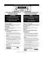
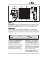
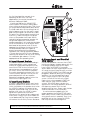
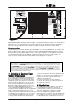
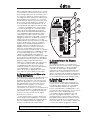
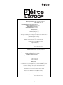
Yorkville
OWNER’S MANUAL
MANUEL de L’UTILISATEUR
YS TYPE: ES700P
LS700P
Manual-Owners-ls700p-1v1.pdf
IMPORTANT SAFETY INSTRUCTIONS
INSTRUCTIONS PERTAINING TO A RISK
OF FIRE, ELECTRIC SHOCK,
OR INJURY TO PERSONS.
INSTRUCTIONS RELATIVES AU RISQUE
DE FEU, CHOC ÉLECTRIQUE, OU
BLESSURES AUX PERSONNES.
CAUTION:
AVIS:
TO REDUCE THE RISK OF ELECTRIC SHOCK, DO
NOT REMOVE COVER (OR BACK).
NO USER SERVICEABLE PARTS INSIDE.
AFIN DE REDUIRE LES RISQUE DE CHOC ELECTRIQUE,
N’ENLEVEZ PAS LE COUVERT (OU LE PANNEAU
ARRIERE). NE CONTIENT AUCUNE PIECE REPARABLE
PAR L’UTILISATEUR.
REFER SERVICING TO QUALIFIED
SERVICE PERSONNEL.
CONSULTEZ UN TECHNICIEN QUALIFIE
POUR L’ENTRETIENT.
Read Instructions:
Veuillez lire le manuel:
The Owner’s Manual should be read and understood
before operation of your unit. Please, save these
instructions for future reference.
Il contient des informations qui devraient êtres comprises avant
l’opération de votre appareil. Conservez S.V.P. ces instructions
pour consultations ultérieures
Packaging:
Emballage:
Keep the box and packaging materials, in case the unit
needs to be returned for service.
Conservez la boite au cas ou l’appareil devait être
retourner pour réparation.
Warning:
Warning:
When using electric products, basic precautions should
always be followed, including the following:
Attention: Lors de l’utilisation de produits électrique,
assurez-vous d’adhérer à des précautions de bases
incluant celle qui suivent:
Power Sources:
Your unit should be connected to a power source only of the
voltage specified in the owners manual or as marked on the unit.
This unit has a polarized plug. Do not use with an extension cord or
receptacle unless the plug can be fully inserted. Precautions should
be taken so that the grounding scheme on the unit is not defeated.
Hazards:
Do not place this product on an unstable cart, stand, tripod, bracket or
table. The product may fall, causing serious personal injury and serious
damage to the product. Use only with cart, stand, tripod, bracket, or table
recommended by the manufacturer or sold with the product. Follow the
manufacturer’s instructions when installing the product and use mounting
accessories recommended by the manufacturer.
The apparatus should not be exposed to dripping or splashing
water; no objects filled with liquids should be placed on the
apparatus.
Terminals marked with the “lightning bolt” are hazardous live;
the external wiring connected to these terminals require installation
by an instructed person or the use of ready made leads or cords.
No naked flame sources, such as lighted candles, should be
placed on the apparatus.
Alimentation:
L’appareil ne doit être branché qu’à une source d’alimentation
correspondant au voltage spécifié dans le manuel ou tel qu’indiqué
sur l’appareil. Cet appareil est équipé d’une prise d’alimentation
polarisée. Ne pas utiliser cet appareil avec un cordon de
raccordement à moins qu’il soit possible d’insérer complètement les
trois lames. Des précautions doivent êtres prises afin d’eviter que le
système de mise à la terre de l’appareil ne soit désengagé.
Hazard:
The AC supply cord should be routed so that it is unlikely that it will
be damaged. If the AC supply cord is damaged DO NOT
OPERATE THE UNIT.
Ne pas placer cet appareil sur un chariot, un support, un trépied ou une
table instables. L’appareil pourrait tomber et blesser quelqu’un ou subir des
dommages importants. Utiliser seulement un chariot, un support, un trépied
ou une table recommandés par le fabricant ou vendus avec le produit.
Suivre les instructions du fabricant pour installer l’appareil et utiliser les
accessoires recommandés par le fabricant.
Il convient de ne pas placer sur l’appareil de sources de flammes
nues, telles que des bougies allumées.
L’appeil ne doit pas être exposé à des égouttements d’eau ou des
éclaboussures et qu’aucun objet rempli de liquide tel que des vases
ne doit être placé sur l’appareil.
Les dispositifs marqués d’une symbole “d’éclair” sont des parties
dangereuses au toucher et que les câblages extérieurs connectés à
ces dispositifs de connection extérieure doivent être effectivés par un
opérateur formé ou en utilisant des cordons déjà préparés.
Service:
Cordon d’alimentation:
The unit should be serviced only by qualified service personnel.
Évitez d’endommager le cordon d’alimentation. N’UTILISEZ PAS
L’APPAREIL si le cordon d’alimentation est endommagé.
Power Cord:
Service:
Consultez un technicien qualifié pour l’entretien de votre appareil.
SAFE_V4.doc Version 4.0 02/11/99 11:54 AM
POWER
AMPLIFIER
ES700P
POWER
Yorkville
FULL–RANGE
SPEAKERS
SUBWOOFER
Left
125 Hz
HIGH
FREQUENCY
CUT OFF
Left
Right
Right
LS700P
ONE SUBWOOFER PER SYSTEM
100 Hz
DESIGNED & MANUFACTURED BY YORKVILLE SOUND • TORONTO, CANADA
This Subwoofer may be driven from Speaker Level
or Line Level signals. If an élite processor is used,
this Subwoofer should be plugged into the SUB
output of the processor. The High–Frequency
Cutoff should be set to 150-Hz and the Input Level
should be set to LINE. For Line
Level operation a balanced (Tip
Ring Sleeve) cable should be
used. If the system is being
INPUT GROUND
operated without a processor,
UNGROUNDED
this Subwoofer can be
GROUNDED
connected to the output of the
power amplifier as shown in the INPUT LEVEL
SPEAKER
diagrams and the Input Level
should be set to SPEAKER. If
LINE
none of the equipment has a Uground, the INPUT GROUND
should be set to GROUNDED.
Otherwise the INPUT GROUND
I
should be set to the position that
N
best minimizes the hum.
LEFT
P
(mono)
U
Refer to the Owner's
T
T 3,15A GDC
T 5.0A 250V
ON POWER
SLO~BLO
230V
50Hz
1.3A
Yorkville
CAUTION: REPLACE WITH
SAME TYPE FUSE AND RATING
120V
60Hz
LR 21877 2.5A
ATTENTION: UTILISER UN FUSIBLE DE
RECHANGE DE MEME TYPE ET CALIBRE
150 Hz
SUBWOOFER
LEVEL
+3 +10
USER NOTE:
+20
0
+30
-3
dB
Manual for other modes
of operation
CAUTION AVIS
PARALLEL
THRU
RIGHT
L
R
FULL–RANGE
SPEAKER
FULL–RANGE
SPEAKER
ES700P
SUBWOOFER
POWER
AMPLIFIER
I
N
P
U
T
PARALLEL
THRU
ES700P
SUBWOOFER
TWO SUBWOOFERS PER SYSTEM
Introduction
The LS700P is a premium quality integrated powered subwoofer and amplifier. Created
as an easy-to-setup addition to your PA, the LS700P will extend the bass of a typical
sound system with a minimum of complication, and hence is intended primarily to
operate with speaker level signals.
Configuration
The LS700P may be used in several different configurations, the minimum standard
system is one LS700P used with a pair of full range speakers. The LS700P accepts the
signal from separate Left and Right sources simultaneously. It then combines them into
one signal (to drive the internal speakers). When used in a setup where only one signal is
provided to a speaker, such as a mono system or stereo with more than one LS700P, use
either the Left or Right input.
For normal operation connect the LS700P just like an ordinary speaker along with the full range speakers. The
"INPUT LEVEL" switch should be set to "SPEAKER." If the audio source does not have a "U" ground, eg. a ground pin on
the AC cord, the "INPUT GROUND" switch must be set to "GROUNDED." The LS700P may be wired before or after
the full range speakers. Use the left and right inputs when using a single LS700P in a stereo system. Use either
the left or right inputs when using separate LS700P 's for each side or when used in a mono system. The
LS700P does not alter the signal to the full range speakers in any way. The LS700P will not draw any
power from the amplifier driving the full range speakers. Please note that an external cross-over is not necessary.
1. Hi Frequency Cutoff Control
2. Subwoofer Level Control
This control varies the frequency at
which the LS700P rolls off the high
frequencies. This provides part of a
crossover function. This crossover
function also combines with the natural
low frequency roll off inherent of the full
range cabinet (when the LS700P is not
used with an élite processor). This control
should be set to the closest possible
frequency to 20 Hz below the crossover
point that the full range speakers
processor uses as it's crossover point.
If an élite processor is used, set the high
frequency cutoff to maximum (160 Hz)
The subwoofer level control adjusts the
amount of bass added to the sound
system by the LS700P. This adjusts for the
relative sensitivity of the companion full
range speakers and the desired system
frequency response. This control should
be set by listening while operating at a
medium level and then not changed. It
is not possible to set this control properly
at high levels since the limiter is
determining the output level. Setting the
level too high will over load the circuitry
causing a loss of bass dynamics. The
level control should not be set above
1
1
the 9 o’clock position except when
operating at low levels. For most
applications the control should be set
between 0dB and +20dB.
A setting of 0dB on the SUBWOOFER
LEVEL control is the correct starting point
when setting up a sound system. From there
the sound can be adjusted for best sound.
The 0 dB mark refers to the setting that will
give full power when the line input is used
and the input signal is at a level of +4 dBV.
This also is the setting to give a sensitivity of
2.83 Vrms (1 watt 8-Ohms) for 100 dB spl
when set for speaker level input. With a
typical full range companion speaker this
will give flat response. In either line or
speaker operation it will usually be desirable
to set the control at +3 to +6 to give some
bass boost at low power levels. At levels
approaching full power the built-in limiter
will automatically reduce the gain to
prevent over powering the subwoofer.
Operation with settings significantly above
+12 may clip the circuitry in the subwoofer
reducing the dynamics of the music. Setting
the subwoofer gain above +12 is only
appropriate at low operating level.
2
POWER
Yorkville
125 Hz
HIGH
FREQUENCY
CUT OFF
LS700P
100 Hz
DESIGNED & MANUFACTURED BY YORKVILLE SOUND • TORONTO, CANADA
150 Hz
SUBWOOFER
LEVEL
+3 +10
USER NOTE:
This Subwoofer may be driven from Speaker Level
or Line Level signals. If an élite processor is used,
this Subwoofer should be plugged into the SUB
output of the processor. The High–Frequency
Cutoff should be set to 150-Hz and the Input Level
should be set to LINE. For Line
Level operation a balanced (Tip
Ring Sleeve) cable should be
used. If the system is being
INPUT GROUND
operated without a processor,
UNGROUNDED
this Subwoofer can be
GROUNDED
connected to the output of the
power amplifier as shown in the INPUT LEVEL
SPEAKER
diagrams and the Input Level
should be set to SPEAKER. If
LINE
none of the equipment has a Uground, the INPUT GROUND
should be set to GROUNDED.
Otherwise the INPUT GROUND
should be set to the position that
best minimizes the hum.
LEFT INPUT
3
+20
0
+30
-3
dB
4
(mono)
Refer to the Owner's
Manual for other modes
of operation
PARALLEL
THRU
5
RIGHT INPUT
PARALLEL
THRU
5. Stereo Input and Parallel
Thru Jacks
3. Input Ground Switch
For normal operation, connect the LS700P
just like an ordinary speaker, along with the
Full-Range speakers and set the Input
Level switch to SPEAKER. If the audio
source does not have a ground pin on the
AC cord, the Input Ground switch must be
set to GROUND (GND). The LS700P may be
plugged in before or after the Full-Range
speakers. Use the Left and Right Inputs
when using a single LS700P in a stereo
system. Use either the Left or the Right
inputs when using separate LS700P's for
each side (or when used in a Mono
system). The LS700P does not alter the
signal to the Full-Range speakers, and will
not draw any power from the host
amplifier driving them. Please note that an
external crossover is not necessary.
As well as accommodating the full
range speakers, the PARALLEL THRU jacks
allow many LS700Ps to be connected in a
string (or otherwise in parallel). There is no
practical limit to the number of LS700Ps
that may be connected together.
The LS700P expects the source feeding it
to be grounded. A system comprised
entirely of ungrounded equipment may
cause the LS700P to hum or buzz. If you
have a buzz or hum problem, try setting
the switch to the "GROUNDED" position.
The switch should otherwise be left in the
"UNGROUNDED" position. Do not use the
grounded position with an amplifier
operating in bridged mode or when the
sleeve of the input signal is live.
4. Input Level Switch
A switch is provided to switch input levels
between speaker level and line level. The
switch should be set to speaker level when
the LS700P is fed from the output of an
amplifier or powered mixer. The line level
position is for when the LS700P is fed a
signal from a processor, electronic
crossover or the output of an unpowered
mixer. When using the line level mode the
use of balanced (Tip, Ring, Sleeve) cables
will reduce the sensitivity to hum and buzz.
AT HIGH POWER LEVELS WHEN THE LIMITER IS OPERATING INCREASING THE SUBWOOFER LEVEL CONTROL WILL NOT
INCREASE THE OUTPUT. DO NOT INCREASE SETTING WHILE OPERATING AT HIGH LEVELS.
2
6. Protection
The LS700P has circuitry to prevent clipping, over current and over excursion. The circuitry
does not alter the frequency response as the level changes. At high levels the limiter will
limit the gain of the LS700P and hence if the user attempts to set the subwoofer level
control at high levels the resulting setting will be incorrect. The level control should be set
while operating at low levels (under 10 watts). If the level control is set to high due to setting
it at high operating levels the input circuit will clip and the dynamics of the bass will be lost.
This can happen without audible distortion since the filters will filter out the distortion.
LS700P CONFIGURATION EXAMPLES
LS700P
SUBWOOFER
Left
FULL–RANGE
SPEAKER
config01e-ls700p.eps
Output
FULL–RANGE
SPEAKER
LS700P
SUBWOOFER
élite PROCESSOR
LS700P
SUBWOOFER
POWER
AMPLIFIER
LS700P
SUBWOOFER
TWO SUBWOOFERS PER SYSTEM
ONE SUBWOOFER, WITH MONO SYSTEM
POWER
AMPLIFIER
Right
FULL–RANGE
SPEAKER/s
config02e-ls700p.eps
POWER
AMPLIFIER
L
INPUT
MID/ SUB
HI OUT
R
INPUT
LS700P
MID/ SUB
HI OUT
SUBWOOFER
FULL–RANGE
SPEAKERS
Left
Left
Right
config03e-ls700p.eps
Right
POWER
AMPLIFIER
Right
R
AMP IN
AMP OUT
L
ONE SUBWOOFER USING ÉLITE PROCESSOR
ONE SUBWOOFER, WITH STEREO SYSTEM
Note: The LS700P built-in stand mounting adapter can be used with Yorkville SW-Teletube accessory to support our
E160 cabinets. The support tube can be adusted up to it’s full 5’4” extension safely as long as the LS700P is not
inclined more than 10˚ (10 degrees).
WARNING: Larger or heavier cabinets should not be used!
3
config04e-ls700p.eps
FULL–RANGE
SPEAKERS
Left
POWER
AMPLIFIER
ES700P
POWER
Yorkville
FULL–RANGE
SPEAKERS
SUBWOOFER
Left
125 Hz
HIGH
FREQUENCY
CUT OFF
Left
Right
Right
LS700P
ONE SUBWOOFER PER SYSTEM
100 Hz
DESIGNED & MANUFACTURED BY YORKVILLE SOUND • TORONTO, CANADA
T 3,15A GDC
T 5.0A 250V
ON POWER
SLO~BLO
230V
50Hz
1.3A
Yorkville
CAUTION: REPLACE WITH
SAME TYPE FUSE AND RATING
120V
60Hz
LR 21877 2.5A
ATTENTION: UTILISER UN FUSIBLE DE
RECHANGE DE MEME TYPE ET CALIBRE
150 Hz
SUBWOOFER
LEVEL
+3 +10
USER NOTE:
This Subwoofer may be driven from Speaker Level
or Line Level signals. If an élite processor is used,
this Subwoofer should be plugged into the SUB
output of the processor. The High–Frequency
Cutoff should be set to 150-Hz and the Input Level
should be set to LINE. For Line
Level operation a balanced (Tip
Ring Sleeve) cable should be
used. If the system is being
INPUT GROUND
operated without a processor,
UNGROUNDED
this Subwoofer can be
GROUNDED
connected to the output of the
power amplifier as shown in the INPUT LEVEL
SPEAKER
diagrams and the Input Level
should be set to SPEAKER. If
LINE
none of the equipment has a Uground, the INPUT GROUND
should be set to GROUNDED.
Otherwise the INPUT GROUND
I
should be set to the position that
N
best minimizes the hum.
LEFT
P
(mono)
U
Refer to the Owner's
T
+20
0
+30
-3
dB
Manual for other modes
of operation
CAUTION AVIS
PARALLEL
THRU
RIGHT
L
R
FULL–RANGE
SPEAKER
FULL–RANGE
SPEAKER
ES700P
SUBWOOFER
POWER
AMPLIFIER
I
N
P
U
T
PARALLEL
THRU
ES700P
SUBWOOFER
TWO SUBWOOFERS PER SYSTEM
Introduction
L'enceinte acoustique amplifiée LS700P intègre un haut-parleur d'extrême grave à un amplificateur
de puissance. Conçu principalement pour être utilisée avec des signaux de niveau haut-parleur,
elle a été créé pour rehausser, avec simplicité, les basses fréquences d'un ensemble audio.
Configuration
On peut utiliser le LS700P dans plusieurs types d'installation. Le système standard inclu un LS700P et une
paire de cabinets pleine gamme. Le LS700P accepte les signaux indépendants de gauche et droite
provenant des enceintes pleine gamme et les combine pour entraîner son haut-parleur interne. Dans
un ensemble qui n'amène qu'un signal au LS700P, par exemple un système monophonique ou un
ensemble stéréo qui utilise plusieurs LS700P, utilisez l'entrée de gauche ou de droite.
Pour opération normale, branchez simplement le LS700P comme un cabinet ordinaire avec les cabinets pleine
gamme. Réglez le commutateur "INPUT LEVEL" à la position "SPEAKER." Le commutateur "INPUT GROUND" doit être
réglé à la position "GROUNDED" si l'appareil de source sonore n'est pas munis d'un cordon d'alimentation avec lame
de mise à la terre. Le LS700P peut être branché avant ou après les cabinets pleine gamme. Si vous n'utilisez
qu'un LS700P dans un ensemble stéréo, utilisez les entrées gauche et droite. Utilisez l'entrée de gauche ou
droite dans un ensemble avec plusieurs LS700P ou encore dans un ensemble monophonique. Le signal
acheminé aux haut-parleurs pleine gamme n'est pas modifié par le LS700P. Le LS700P ne consomme
pas de courant provenant de l'amplificateur qui amène le signal aux cabinets pleine gamme. Notez qu'il n'est pas
nécessaire d'utiliser un filtre séparateur externe.
contrôle au minimum. Il peut être préférable de
régler ce contrôle à une basse fréquence si le
LS700P est situé à une bonne distance des
cabinets pleine gamme.
1. Contröle de Coupure Pour
Hautes Fréquences
Ce contrôle règle la fréquence qui marque le
point de départ pour la pente de diminution
des hautes fréquences. Lorsqu'utilisé sans filtre
séparateur électronique externe, tel l'unité de
traitement élite, le filtre interne en conjonction
avec la pente de diminution des fréquences
basses du cabinet pleine gamme, pourvoi un
dispositif complet de filtrage de fréquences. Ce
contrôle devrait être réglé à la fréquence
assignée à l'unité de traitement élite qui fait pair
avec le cabinet pleine gamme élite ( ex. les
cabinets e160 avec l'unité de traitement ep160).
Lorsqu'utilisé avec les cabinets e160 ou e168, le
contrôle devrait être réglé au maximum. Avec
tout autre unité de traitements élite, réglez le
Si un processeur élite est utilisé, réglez le
contrôle de coupure pour hautes fréquences
au maximum (160Hz).
2. Egalisation
Le contrôle de niveau du subwoofer ajuste le
niveau de basses fréquences ajouté au
système par le LS700P. Il permet d’obtenir la
réponse en fréquences désirée en relation
avec la sensibilité du haut-parleur pleine
gamme jumelé. Cet ajustement devrait être fait
en opérant le système à un niveau modéré et
ne devrait pas être modifié par la suite. Il n’est
4
pas possible de régler le niveau de ce contrôle
lors d’opération à niveaux élevés parce que le
limiteur intégré détermine le niveau de sortie. Si
le contrôle est réglé à un niveau trop élevé, le
survoltage du circuit causera une réduction de
la dynamique pour les basses. Le contrôle ne
devrait pas être réglé à une position plus élevé
que “9 heure” à part durant une opération à
un niveau réduit. Dans la plupart des cas, le
contrôle devrait être réglé entre 0dB et +20dB.
1
2
POWER
Yorkville
125 Hz
HIGH
FREQUENCY
CUT OFF
LS700P
100 Hz
DESIGNED & MANUFACTURED BY YORKVILLE SOUND • TORONTO, CANADA
Lorsque vous préparez votre système audio,
commencez par régler le contrôle de niveau
subwoofer level à 0dB. Réglez le ensuite au
niveau désiré. La marque de 0dB indique que
vous obtiendrez la pleine puissance lorsque
l’entrée ligne est utilisé et que le niveau de
signal qui y est présent est de +4dB. C’est aussi le
réglage qui offrira une sensibilité de 2.83Vrms (1
watt 8-Ohms) pour une pression sonore de
100dB quand le sélecteur d’entrée est réglé à la
position “speaker level.” Dans un ensemble
typique avec haut-parleur pleine bande, ce
réglage offrira une courbe de réponse en
fréquence uniforme. Lorsque le système est
utilisé à un niveau réduit, peut importe si le
sélecteur d’entrée est réglé à “Line” ou “Speaker
Level,” il est généralement souhaitable de régler
le contrôle de niveau entre +3 et +6 pour
obtenir une augmentation des graves. Le
limiteur intégré réduira automatiquement le gain
pour éviter que trop de puissance n’atteigne le
haut-parleur lorsque le système est utilisé à des
niveaux se rapprochant de la puissance
maximum. Le signal du subwoofer sera écrêté si
vous opérez le système avec des réglages
considérablement plus élevés que +12. Le
résultat en sera une sonorité moins dynamique.
Un tel réglage du contrôle de gain du
subwoofer (+12) n’est approprié que lorsque
vous opérez le système à des niveau réduits.
150 Hz
SUBWOOFER
LEVEL
+3 +10
USER NOTE:
This Subwoofer may be driven from Speaker Level
or Line Level signals. If an élite processor is used,
this Subwoofer should be plugged into the SUB
output of the processor. The High–Frequency
Cutoff should be set to 150-Hz and the Input Level
should be set to LINE. For Line
Level operation a balanced (Tip
Ring Sleeve) cable should be
used. If the system is being
INPUT GROUND
operated without a processor,
UNGROUNDED
this Subwoofer can be
GROUNDED
connected to the output of the
power amplifier as shown in the INPUT LEVEL
SPEAKER
diagrams and the Input Level
should be set to SPEAKER. If
LINE
none of the equipment has a Uground, the INPUT GROUND
should be set to GROUNDED.
Otherwise the INPUT GROUND
should be set to the position that
best minimizes the hum.
LEFT INPUT
3
+20
0
+30
-3
dB
4
(mono)
Refer to the Owner's
Manual for other modes
of operation
PARALLEL
THRU
5
RIGHT INPUT
PARALLEL
THRU
4. Commutateur de Niveau
d'Entrée
Le LS700P est muni d'un commutateur qui
permet de sélectionner aux entrées, les signaux
de niveau haut-parleur ou de niveau ligne.
L'opération à niveau ligne est appropriée
seulement lorsqu'un unité de traitement avec
fréquence de coupure à 125Hz ou moins est
utilisé. Tout autre mode d'opération devrait être
fait avec des signaux de niveau haut-parleur et
le commutateur à la position "SPEAKER LEVEL."
3. Commutateur de Mise a la
Terre Del'Entree
Le LS700P a été conçu pour être alimenté avec
une source qui est branchée à la terre. Un
problème de ronflement ou bourdonnement
peut être causé par un système comprenant
des appareils sans mise à la masse. Si un tel
problème survient, réglez le commutateur
"INPUT GROUND SWITCH" à la position
"GROUNDED," sinon, laissez le commutateur à la
position "UNGROUDED." N'utilisez pas la position
"GROUNDED" avec un amplificateur branché
en pont ou lorsque le manchon du signal
d'entrée est sous tension.
5. Entrée Stereo et Jacks
Parallel Thru
Pour opération normale, reliez simplement le
LS700P comme un haut-parleur ordinaire avec
les cabinets pleine gamme. Le commutateur
“NIVEAU D'ENTREE” devrait être réglé à la
position “HAUT-PARLEUR.” Si l'appareil de source
n'est pas doté de mise à la terre, (tel une mise à
la terre sur le cordon d'alimentation), le
commutateur de découplage de mise à la
terre doit être réglé à la position “GND.” Le
LS700P peut être connecté avant ou après les
haut-parleurs pleine gamme. Utilisez les entrées
de gauche et de droite lors d’opération à un
seul LS700P dans un système stéréo. Utilisez l’une
ou l’autre des entrées de gauche et droite
A des niveaux élevés, lorsque le limiteur est
activé, augmenter le réglage du contrôle de
niveau n'augmentera pas le niveau de signal
de sortie. N'augmentez pas le réglage du
niveau lors d'opération à niveaux élevés.
A des niveaux élevés, lorsque le limiteur est activé, augmenter le réglage du contrôle de niveau n'augmentera pas
le niveau de signal de sortie. N'augmentez pas le réglage du niveau lors d'opération à niveaux élevés.
5
lorsque vous utilisez deux LS700P, un pour le côté droit et un pour le côté gauche ( ou dans un
système monophonique). Le LS700P ne modifie pas le signal acheminé aux haut-parleurs pleine
gamme. Le LS700P ne prélèvera pas de puissance de l'amplificateur qui propulse les haut-parleurs
pleine gamme. Veuillez noter qu'un filtre séparateur externe n'est pas nécessaire.
En plus d'accommoder le cabinet pleine gamme, le jack PARALLEL THRU permet l'utilisation de
plusieurs LS700P branchés en parallèle. Il n'y a pas de limite au nombre de LS700P qui peuvent êtres
raccordés ensemble.
6. CONTROLE DE NIVEAU DU LS700P
Pour ajuster le niveau de basse à ajouter à l'ensemble audio, un contrôle de niveau est prévu au
panneau arrière du LS700P. Ce contrôle règle le niveau par rapport à la sensibilité relative du
cabinet pleine gamme qui l'accompagne et permet d'obtenir la réponse en fréquence désirée.
Ce contrôle devrait être réglé à un niveau moyen d'opération pour ensuite demeurer inchangé.
Puisque le limiteur détermine le niveau de sortie, il est impossible de régler ce contrôle à des
niveaux élevés.
LS700P EXAMPLES DE CONFIGURATION
Gauche
LS700P
Droitie
Enceinte/s
Pleine Gamme
ENCEINTE
PLEINE GAMME
config01f-ls700p.eps
Sortie
ENCEINTE
PLEINE GAMME
LS700P
UN LS700P AVEC SYSTÈME MONO
AMPLIFICATEUR
LS700P
config02f-ls700p.eps
AMPLIFICATEUR
DEUX LS700P PAR SYSTÈME
élite PROCESSEUR
AMPLIFICATEUR
LS700P
L
INPUT
ENCEINTES
PLEINE GAMME
MID/ SUB
HI OUT
R
INPUT
MID/ SUB
HI OUT
LS700P
Gauche
Gauche
Gauche
ENCEINTES
PLEINE GAMME
AMPLIFICATEUR
config03f-ls700p.eps
Droite
Droite
R
ENTRÉE
SORTIES
L
UN LS700P AVEC SYSTEME STÉRÉO
UN LS700P AVEC PROCESSEUR ÉLITE
NOTEZ BIEN: L’adapteur de support LS700P peut être utilisé avec l’accessoire YORKVILLE SW-Teletube pour supporter
les enceintes E160. Le tube de support peut être ajusté à sa pleine extension de 5’4” avec sécurité guand le LS700P
est incliné à moin de 10˚ par rapport à l’horizontale.
ATTENTION: Les enceintes plus larges où lourdes ne doivent pas être utilisé.
6
config04f-ls700p.eps
Droite
Yorkville
LS700P
SPECIFICATIONS
Power Requirements:
Power Amplifier Power (internal):
Frequency response:
Input Impedance:
Speaker components:
120V: 117V-120V AC 60 Hz 2.5A
230V: 230VAC 50 Hz 1.3A
700 Watts
45 Hz to 125 Hz
80 kOhms
2 x 10 inch
Input Connections
Tip: Positive (+ve)
Ring(Shaft): Negative (-ve)
Grounding:
The sleeves of the input are not grounded except when the input ground switch is
set to gnd. Grounding is done through a 100 ohm protection device in order to
prevent damage due to miswiring.
Limiting:
Clipping, excursion and average voice coil current, thermal
Maximum SPL:
Weight:
Dimensions (WxDxH):
131 dB (60 Hz to 110 Hz)
93 lb. (42 kg)
24 inches x 24.5 inches x 17.5 inches
61 cm x 62.1 cm x 44.5 cm
Puissance Requise: 120V: 117V-120V AC 60 Hz 2.5A
230V: 230VAC 50 Hz 1.3A
L'amplificateur de puissance (interne):
réponse de fréquence:
impédance d'entrée:
composants de haut-parleur:
700 Watts
45 Hz à 125 Hz
80 kOhms
2 x 10"
Raccordements d'Entrée:
pointe: positif (+ve)
bague: négatif (-ve)
Mise à la terre
Les manchons des entrées ne sont pas raccordés à la masse sauf quand le
commutateur de mise à la terre d'entrée est réglé à la position "GND." La mise à
la terre est effectuée par un dispositif de protection de 100 ohms de façon à
empêcher les dommages causés par une erreur de branchement.
Limiteur:
écrêtage, excursion et moyenne du courant à la bobine mobile
Pression Sonore Maximum:
Poids:
Dimensions (L x P x H)::
131 dB (60 Hz à 110 Hz)
93 lb. (42 kg)
24" x 24.5" x 17.5"
61 cm x 62.1 cm x 44.5 cm
7
WEB: www.yorkville.com
WORLD HEADQUARTERS
CANADA
U.S.A.
Yorkville Sound
Yorkville Sound Inc.
550 Granite Court
Pickering, Ontario
L1W-3Y8 CANADA
4625 Witmer Industrial Estate
Niagara Falls, New York
14305 USA
Voice: (905) 837-8481
Fax: (905) 837-8746
Voice: (716) 297-2920
Fax: (716) 297-3689
Quality and Innovation Since 1963
Printed in Canada