1
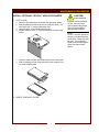
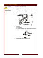
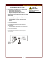
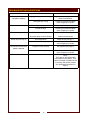
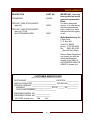
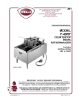
205m
OPERATION MANUAL
MODEL
FT-18M
FINISHING
TOASTER
Includes
INSTALLATION
USE & CARE
Model FT-18M with Optional
Teflon™ Non-Stick Sheets
IMPORTANT: DO NOT DISCARD THIS MANUAL
This manual is considered to be part of the appliance and is to be given to the OWNER or
MANAGER of the restaurant, or to the person responsible for TRAINING OPERATORS of
this appliance. Additional manuals are available from your WELLS DEALER.
THIS MANUAL MUST BE READ AND UNDERSTOOD BY ALL PERSONS USING OR
INSTALLING THIS APPLIANCE. Contact your WELLS DEALER if you have any
questions concerning installation, operation or maintenance of this equipment.
p/n 305092 Rev. (-)
M205m 112102 cps
LIMITED WARRANTY STATEMENT
Unless otherwise specified, all commercial cooking equipment manufactured by WELLS MFG. CO. is warranted
against defects in materials and workmanship for a period of
one year from the date of original installation or 18 months
from the date of shipment from our factory, whichever
comes first, and is for the benefit of the original purchaser
only.
THIS WARRANTY IS THE COMPLETE AND ONLY WARRANTY, EXPRESSED OR IMPLIED IN LAW OR IN FACT,
INCLUDING BUT NOT LIMITED TO, WARRANTIES OF
MERCHANTABILITY OR FITNESS FOR ANY PARTICULAR PURPOSE, AND/OR FOR DIRECT, INDIRECT OR
CONSEQUENTIAL DAMAGES IN CONNECTION WITH
WELLS MFG. CO. PRODUCTS. This warranty is void if it
is determined that, upon inspection by an authorized service
agency, the equipment has been modified, misused, misapplied, improperly installed, or damaged in transit or by fire,
flood or act of God. It also does not apply if the serial nameplate has been removed, or if service is performed by unau-
thorized personnel. The prices charged by Wells Mfg. Co.
for its products are based upon the limitations in this warranty. Seller’s obligation under this warranty is limited to the
repair of defects without charge by a Wells Mfg. Co. factory
authorized service agency or one of its sub-service agencies. This service will be provided on customer’s premises
for non-portable models. Portable models (a device with a
cord and plug) must be taken or shipped to the closest authorized service agency, transportation charges prepaid, for
service. In addition to restrictions contained in this warranty,
specific limitations are shown in the Service Policy and Procedure Guide. Wells Mfg. Co. authorized service agencies
are located in principal cities. This warranty is valid in the
United States and Canada and void elsewhere. Please consult your classified telephone directory, your foodservice
equipment dealer or write the Factory Service Department,
Wells Manufacturing Company, P.O. Box 280, Verdi, Nevada 89439, phone (775) 689-5700 or fax (888) 492-2783,
for information and other details concerning warranty.
SERVICE POLICY AND PROCEDURE GUIDE
ADDITIONAL WARRANTY EXCLUSIONS
1.
2.
3.
4.
5.
6.
Resetting of safety thermostats, circuit breakers, over
load protectors, and/or fuse replacements are not
covered by this warranty unless warranted conditions
are the cause.
All problems due to operation at voltages or phase
other than specified on equipment nameplates are
not covered by this warranty.
Conversion to correct voltage and/or phase must be
the customer’s responsibility.
All problems due to electrical connections not made
in accordance with electrical code requirements
and wiring diagrams supplied with the equipment are
not covered by this warranty.
Replacement of items subject to normal wear, to
include such items as knobs, light bulbs; and, normal
maintenance functions including adjustments of
thermostats, adjustment of micro switches and
replacement of fuses and indicating lights are not
covered by warranty.
Damage to electrical cords and/or plug due to exposure
to excessive heat are not covered by this warranty.
Full use, care, and maintenance instructions supplied
with each machine. Noted maintenance and
preventative maintenance items, such as servicing and
cleaning schedules, are customer responsibility. Those
miscellaneous adjustments noted are customer
responsibility. Proper attention to preventative
maintenance and scheduled maintenance procedures
will prolong the life of the appliance.
7. Travel mileage is limited to sixty (60) miles from an
Authorized Service Agency or one of its sub-service
agencies.
8. All labor shall be performed during regular working
hours. Overtime premium will be charged to the buyer.
9. All genuine Wells replacement parts are warranted for
ninety (90) days from date of purchase on nonwarranty equipment. This parts warranty is limited only
to replacement of the defective part(s). Any use of
non-genuine Wells parts completely voids any
warranty.
10. Installation, labor, and job check-outs are not
considered warranty and are thus not covered by this
warranty.
11. Charges incurred by delays, waiting time or operating
restrictions that hinder the service technician’s ability to
perform service are not covered by warranty. This
includes institutional and correctional facilities.
SHIPPING DAMAGE CLAIM PROCEDURE
NOTE: For your protection, please note that equipment in
this shipment was carefully inspected and packaged by
skilled personnel before leaving the factory. Upon acceptance of this shipment, the transportation company assumes
full responsibility for its safe delivery.
IF SHIPMENT ARRIVES DAMAGED:
1. VISIBLE LOSS OR DAMAGE: Be certain that any
visible loss or damage is noted on the freight bill or
express receipt, and that the note of loss or damage is
signed by the delivery person.
2. FILE CLAIM FOR DAMAGE IMMEDIATELY:
Regardless of the extent of the damage.
3.
CONCEALED LOSS OR DAMAGE: if damage is
unnoticed until the merchandise is unpacked, notify the
transportation company or carrier immediately, and file
“CONCEALED DAMAGE” claim with them. This
should be done within fifteen (15) days from the date
the delivery was made to you. Be sure to retain the
container for inspection.
Wells Manufacturing cannot assume liability for damage or
loss incurred in transit. We will, however, at your request,
supply you with the necessary documents to support your
claim.
xi
TABLE OF CONTENTS
WARRANTY
SPECIFICATIONS
FEATURES & OPERATING CONTROLS
PRECAUTIONS & GENERAL INFORMATION
AGENCY LISTING INFORMATION
INSTALLATION
OPERATION
CLEANING INSTRUCTIONS
MAINTENANCE PROCEDURES
TROUBLESHOOTING SUGGESTIONS
PARTS & SERVICE
CUSTOMER SERVICE DATA
xi
1
2
3
4
4
5
6
7
12
13
13
INTRODUCTION
Thank You for purchasing this Wells Manufacturing Co. appliance.
Proper installation, professional operation and consistent maintenance of this appliance will ensure that it
gives you the very best performance and a long, economical service life.
This manual contains the information needed to properly install this appliance, and to use and care for the
appliance in a manner which will ensure its optimum performance.
SPECIFICATIONS
HEIGHT
PLATEN FULLY
RAISED
WIDTH
DEPTH
Model FT-18M
32"
21"
27"
ELECTRICAL
VOLTAGE
AMPS
WATTS
POWER CORD
Model FT-18M
208 VAC 1ø
20.2 Amps
4200 Watts
NEMA 6-30P
240 VAC 1ø
23.3 Amps
5600 Watts
DIMENSIONS
1
FEATURES & OPERATING CONTROLS (continued)
2
PRECAUTIONS AND GENERAL INFORMATION
This appliance is intended for use in commercial establishments
only.
This appliance is intended to prepare food for human consumption.
No other use is recommended or authorized by the manufacturer or its
agents.
Operators of this appliance must be familiar with the appliance use,
limitations and associated restrictions. Operating instructions must be
read and understood by all persons using or installing this appliance.
Cleanliness of this appliance is essential to good sanitation. Read and
follow all included cleaning instructions and schedules to ensure the
safety of the food product.
Disconnect this appliance from electrical power before performing any
maintenance or servicing.
DO NOT submerge this appliance in water. This appliance is not jet
stream approved. Do not direct water jet or steam jet at this appliance,
or at any control panel or wiring. Do not splash or pour water on, in or
over any controls, control panel or wiring. Do not wash floor around
this appliance with water or steam jet.
Exposed surfaces of this appliance can be hot to the touch and may
cause burns.
Griddle surfaces will be very hot when in use. Contact will cause
severe injury.
Do not operate this appliance if the keypad section of the control panel
is torn or broken. Call your Authorized Wells Service Agent for service.
The technical content of this manual, including any wiring diagrams,
schematics, parts breakdown illustrations and/or adjustment
procedures, is intended for use by qualified technical personnel.
Any procedure which requires the use of tools must be performed by a
qualified technician.
This manual is considered to be a permanent part of the appliance.
This manual and all supplied instructions, diagrams, schematics, parts
breakdown illustrations, notices and labels must remain with the
appliance if it is sold or moved to another location.
This appliance is made in the USA. Unless otherwise noted, this
appliance has American sizes on all hardware.
3
WARNING:
Electric
Shock hazard
All servicing requiring
access to non-insulated electrical components must be
performed by a factory authorized
technician.
DO NOT open any access
panel which requires the use
of tools. Failure to
follow this warning can
result in severe electrical
shock.
WARNING:
BURN HAZARD
Griddle surfaces will be very
hot when in use. Contact will
cause severe injury.
CAUTION:
Risk of
Damage
DO NOT connect or
energize this appliance
until all installation
instructions are read and
followed. Damage to the
appliance will result if
these instructions are not
followed.
CAUTION:
Hot Surface
Exposed surfaces can be hot
to the touch and may cause
burns.
AGENCY LISTING INFORMATION
STD 4
This appliance conforms to NSF Standard 4 for sanitation only if
installed in accordance with the supplied Installation Instructions and
maintained according to the instructions in this manual.
This appliance is
U Listed under UL File E6070 for 208V and 240V.
This appliance is
V Listed under UL File E6070 for 208V and 240V .
E6070
E6070
INSTALLATION
NOTE: DO NOT discard
the carton or other packing
materials until you have
inspected the appliance for
hidden damage and tested it
for proper operation.
Refer to SHIPPING DAMAGE
CLAIM PROCEDURE on the
inside front cover of this
manual.
WARNING:
Risk of
personal injury
Installation procedures must
be performed by a qualified
technician with full knowledge
of all applicable electrical and
plumbing codes. Failure can
result in personal injury and
property damage.
CAUTION:
ELECTRIC SHOCK
HAZARD
This appliance is
equipped with a grounding
system to protect you from
electrical shock in the event of
internal damage. DO NOT cut
or remove the large ground
prong on the plug. DO NOT
twist any blade on the plug
to fit an existing receptacle.
UNPACKING & INSPECTION
Carefully remove the appliance from the carton. Remove all
protective plastic film, packing materials and accessories from the
Appliance before connecting electrical power or otherwise performing
any installation procedure.
Carefully read all instructions in this manual and the Installation
Instruction Sheet packed with the appliance before starting any
installation.
Read and understand all labels and diagrams attached to the
appliance.
Carefully account for all components and accessories before
discarding packing materials. Store all accessories in a convenient
place for later use.
SETUP
Setup the appliance only on a firm, level surface. Verify local codes
for requirements. Concrete, tile, terrazzo or metal surfaces are
recommended.
Install provided 4" adjustable legs, one on each corner of the appliance,
in the holes provided. Verify that the unit sits firmly ON ALL FOUR
LEGS. With a spirit level, check that the appliance is level front-to-back
and side-to-side. With the adjustable legs, adjust as required to level
the appliance. All four legs must be adjusted to firmly contact the
countertop in order to prevent tipping.
Install one non-stick sheet on each upper platen.
Refer to the Installation Instruction Sheet for required clearances.
Maintain required clearances between the appliance and adjacent
combustible surfaces.
Avoid storing flammable or combustible materials in, on or near the
appliance.
ELECTRICAL
This appliance requires a properly grounded 30 amp 208 or 240 VAC
single phase circuit and NEMA 6-30R receptacle.
4
OPERATION
WARM-UP
CAUTION:
During warm-up, both displays flash while showing the last-used MENU
temperature setpoint.
BURN HAZARD
A MENU cycle cannot be started while in warm-up mode.
When setpoint temperature is reached, the display stops flashing and
the audible alert beeps 3 times.
SEASONING THE PLATENS
The platens must be seasoned before attempting to toast product, in
order to provide a hard, non-porous surface.
With the POWER SWITCH ON, press MENU with highest time
(typically Menu 3). When the display stops flashing, brush a liberal coat
of vegetable oil onto exposed surfaces of upper and lower platens.
Lower the upper platens.
At the end of the timed cycle, or when the oil begins to smoke, turn the
POWER SWITCH OFF. Wipe the platen surfaces with a clean dry
cloth.
Repeat three times. Your toaster now seasoned and ready to use.
LOAD PRODUCT
Load product onto lower platen.
Lower upper platen slowly. Platen will level based on thickness of
product.
TIMER OPERATION
Lower upper platen to start the timer countdown. Readout will display
time remaining. The LED for the selected MENU key will glow, and the
display colon will flash while the timer is active.
When the display reaches “_0:00”, the audible alert beeps and the
display flashes. The unit will “beep” three times, then display the
current menu setpoint.
Left and right MENU keys operate independently of each other, and
can be in operation at the same time. The flashing display will indicate
which side has timed out. Each side will “beep” three times at the end
of the timed cycle, then display the current menu setpoint.
Raise upper platen slowly until it is in the full up position. Unload
product from the lower platen.
5
Exposed portions of toaster
are hot. Use care when
working around the platens.
Use insulated handles to
raise and lower platens.
IMPORTANT:
This appliance is designed
for finish toasting only.
Specifically, this appliance is
NOT to be used as a grill or
meat cooking device. It is
not advisable to attempt to
cook or thaw frozen foods on
this appliance. DO NOT
place ice on the platen
surface. The temperature
drop will disable the timer.
NOTE: Timers can be halted
by pressing the MENU key at
any time during the timed
cycle.
To change temperatures and
times, see Programming
Instructions, page 8.
NOTE:
Lowering a platen will start
the countdown timer.
Raising the platen resets the
countdown timer.
CLEANING
CAUTION:
ELECTRIC SHOCK
HAZARD
DO NOT submerge or
immerse toaster in water.
CLEANING INSTRUCTIONS
PRECAUTIONS:
Press MENU 4 (cleaning mode). Allow toaster to
cool to 275ºF.
NOTE: If MENU 4 has been programmed to
anything other than 275ºF, press POWER SWITCH
OFF and allow unit to cool for at least 10 minutes.
Be sure to wear protective gloves.
FREQUENCY:
Daily
TOOLS
Protective gloves
CAUTION:
BURN HAZARD
Exposed portions of toaster
are hot. Use care when
working around the platens.
Use insulated handles to
raise and lower platens.
Cleanser manufactured specifically for use on
toaster surfaces.
Applicator pad with handle
Metal spatula with rounded corners
Clean dry towels.
IMPORTANT: DO NOT SUBMERGE OR IMMERSE TOASTER
IN WATER.
If equipped with optional Teflon™ non-stick sheets:
Remove retaining rods for non-stick sheets. Rods may be cleaned in
the sink. Temporarily place non-stick sheets on a clean flat surface.
• DO NOT fold, crease or lay on sharp objects
• DO NOT hose with water or soak in sink
Place sheets on warm lower platen. Wipe both sides with clean damp
cloth.
Loosen debris on surface of platens with metal spatula.
Apply cleanser to cleaning pad. Scrub exposed surface of upper
platens, first, then scrub exposed surface of lower platen.
Wipe exposed surface with a towel moistened with clear water.
Wipe upper platens first, then lower platen. Rinse the towels often.
Reinstall non-stick sheets on upper platens.
Remove CRUMB TRAY. Wash and rinse, then reinstall.
Wipe outside surfaces with a towel moistened with clear water.
6
MAINTENANCE PROCEDURES
INSTALL OPTIONAL TEFLON™ NON-STICK SHEETS
CAUTION:
BURN HAZARD
1. LEFT PLATEN
a. Raise the left upper platen, and lower the right upper platen.
b. Slide a retaining rod into the pocket of a non-stick sheet. The
short leg of the "L" must go toward the front.
d. Hang the sheet on the outside retaining tabs.
e. Clip the short leg of the "L" into the bracket on the front of the
platen.
f. Wrap the sheet smoothly around the bottom face of the platen.
g. Slide a retaining rod into the pocket of the sheet, trapping it on
the inside retaining tabs.
2. REPEAT FOR RIGHT PLATEN
7
Exposed portions of toaster
are hot. Use care when
working around the platens.
Use insulated handles to
raise and lower platens.
NOTE:
Teflon™ non-stick sheets are
black on one side and brown
on the other. Either side may
be used. For consistency,
Wells recommends using the
same color side on both
platens.
MAINTENANCE PROCEDURES (continued)
CAUTION:
BURN HAZARD
Unplug toaster and allow to
cool before adjusting.
ADJUST PLATEN TENSION
1. ADJUSTMENT LOCATION
a. Right platen tension adjuster is located on back of the toaster,
on back side of the right upright.
b. Left platen tension adjuster is located on back of the toaster,
on front side of the left upright.
2. TO ADJUST
a. Loosen lock nut.
b. Turn adjust screw until platen raises easily, latches securely
in the upright position, and lowers without undue effort.
c. Tighten lock nut while holding adjust screw.
3. Adjust both upper platens to the same "feel".
8
MAINTENANCE PROCEDURES (continued)
PROGRAMMING INSTRUCTIONS:
A. Controller can be configured for use in four different modes:
a.
b.
c.
d.
Single operation with manual timer
Single operation with automatic timer
Single and remote operation with manual timer
Single and remote operation with automatic timer
NOTE: Automatic timing function requires the use of a timing
initiation device.
B. Controller is shipped in configuration d. (Single and remote
operation with automatic timer).
a. To switch between "single" and "single and remote"
operation:
I Turn power switch OFF
IpowerPress
and hold 1st and 3rd keys while turning the
switch ON.
b. To switch between "manual timer" and "automatic timer":
I Turn power switch OFF
IpowerPress
and hold 1st and 4th keys while turning the
switch ON.
9
CAUTION:
BURN HAZARD
Avoid contact with appliance
heating surfaces.
MAINTENANCE PROCEDURES (continued)
During warm-up, both
displays flash while showing
the last-used MENU settings.
A MENU cycle cannot be
started while in warm-up
mode. However, MENU keys
may be programmed during
warm-up.
STANDARD OPERATION NOTES:
Standard pre-set MENU programs are as follow:
PROGRAM
1
2
3
4
TEMP
450º
450º
450º
275º
TIME
00:14
00:27
00:35
00:00
FUNCTION
CLEANING
Program mode is disabled
when either timer is counting
down.
On start-up or changing program settings, the display will flash until the
new temperature setpoint is reached (i.e. heater cycles on or off).
This occurs whether approaching a setpoint from above or below.
A programmed cycle cannot
be started when display is
flashing (warm-up mode).
Both lower platen zones and both upper platens are controlled by the
individual setpoints. Deadband is ±2º.
Any changes to the left preset
timer programs are copied
right section. The right
program settings can then be
changed and stored. Right
program settings are retained
until the left section is
reporgrammed, at which time
left program information is
again copied to the right
section.
When setpoint temperature is
reached, the display stops
flashing and the audible alert
beeps 3 times.
Press TEMP to display actual temperature of the lower platen.
PROGRAMMING TIME AND TEMPERATURE (LEFT SECTION)
NOTE:
• You may program MENU keys during warm-up or during normal
operation.
• Temperature settings are done with the left MENU only.
• Time settings are automatically copied from the LEFTMENU to the
corresponding RIGHTMENU.
• Time settings on the RIGHTMENU may be programmed only after
the LEFTMENU.
Example: Program time and temperature for LEFT MENU 1
Press and hold TEMP. While holding TEMP, press and hold LEFT
MENU 1 key for 3 seconds. The LED above the MENU 1 key will glow,
and the display will read “_ _ : _ _”, prompting you to enter the 4-digit
access code.
Enter the 4-digit code. (NOTE: Factory setting is left MENU 1, left
MENU 2, left MENU3, left MENU 4. Contact your Wells Authorized
Service Agency for instructions in determining or changing your access
code). Starting with the first digit, the bottom bar of the display moves
to the top bar. The security code does not show on the display. Once
the correct code is entered, the display changes to the preset time, and
the LED for MENU 1 key flashes.
10
MAINTENANCE PROCEDURES (continued)
Set the time with MENU 3 (increase) and MENU 4 (decrease). Press
TEMP to save the time.
The display will now advance to show zone temperature setpoints:
1.450 = Zone 1 @ 450ºF
2.450 = Zone 2 @ 450ºF
3.450 = Zone 3 @ 450ºF
4.450 = Zone 4 @ 450ºF
When in program mode, the
timer is displayed as 4 digits
(i.e. 00:15). In regular mode,
the timer is displayed as 3
digits (i.e. _0:15).
NOTE: The manufacturer
advises that product finishing
be controlled with time, and
that MENU 1 - 3 all use the
same temperature setpoint.
The timer is disabled any time
the actual temperature is not
at setpoint, and the time
required to reach the new
temperature (up or down)
may be unacceptable.
Set the temperature setpoint for Zone 1 with MENU 3 (increase) and
MENU 4 (decrease). Press TEMP to advance to next zone.
Repeat for Zone 2, Zone 3, and Zone 4.
Press TEMP to exit program mode for MENU 1 key. The LED will stop
flashing.
MENU 2, MENU 3 and MENU 4 program in a similar manner, except
that the programming mode is entered by pressing TEMP and the
desired LEFT MENU key for 3 seconds.
PROGRAMMING TIME (RIGHT SECTION)
Press and hold TEMP. While holding TEMP, press and hold the desired
RIGHT MENU key for 3 seconds. The LED above the menu key will
glow, and the display will read “_ _ : _ _”, prompting you to enter the 4digit access code.
Enter the 4-digit code. Starting with the first digit, the bottom bar of the
display moves to the top bar. The security code does not show on the
display. Once the correct code is entered, the display changes to the
preset time, and the LED for that MENU key flashes.
When in program mode, the timer is displayed as 4 digits (i.e. 00:15). In
regular mode, the timer is displayed as 3 digits (i.e. _0:15). Set the time
with MENU 3 (increase) and MENU 4 (decrease).
Press the TEMP key to save the time and exit program mode for this
MENU key. The LED will stop flashing.
11
NOTE: LEFT MENU 4
should be programmed for
275º and reserved for
CLEANING.
While in program mode, if no
keystroke is detected within
15 seconds, control reverts to
normal operation. If no
access code, or the wrong
access code, is entered,
control reverts to normal
operation.
TROUBLESHOOTING SUGGESTIONS
SYMPTOM
Toaster will not heat
(no lights or display)
One side does not heat
Food sticks to platen(s)
Platen does not stay up
Timer does not start when
platen is lowered
POSSIBLE CAUSE
SUGGESTED REMEDY
Unplugged or circuit breaker tripped Plug toaster into appropriate circuit.
Reset circuit breaker
Damaged cord or plug
Contact your Authorized Wells
Service Agency for repairs
Zone temp not programmed
Program zone temp (see pg. 8)
Internal damage
Contact your Authorized Wells
Service Agency for repairs
Platens must be seasoned
Season platens (see pg. 5)
Non-stick sheet must be cleaned
Clean non-stick sheets
Out of adjustment
Adjust tension (see pg. 7)
Internal damage
Contact your Authorized Wells
Service Agency for repairs
Program not set correctly
Set program (see page 9)
Internal damage
Contact your Authorized Wells
Service Agency for repairs
NOTE:
There are no user serviceable
components in the toaster. In all
cases of damage or adjustment not
covered by this manual, contact
your Authorized Wells Service
Agency
12
PARTS & SERVICE
DESCRIPTION
PART NO.
CRUMBTRAY
503606
TEFLON™ NON-STICK SHEETS
(pkg of 4)
22876
TEFLON™ NON-STICK SHEETS
(pkg of 4) PLUS
4ea. RETAINING RODS
22877
IMPORTANT: Use only
factory authorized service
parts and replacement
filters.
For factory authorized
service, or to order factory
authorized replacement
parts, contact your Wells
authorized service agency,
or call:
Wells Manufacturing Co.
2 Erik Circle
P. O. Box 280
Verdi, NV 89439
phone: (775) 689-5700
fax:
(888) 492-2783
(Service Parts Dept.)
Service Parts Department
can supply you with the
name and telephone
number of the WELLS
AUTHORIZED SERVICE
AGENCY nearest you.
CUSTOMER SERVICE DATA
please have this information available if calling for service
RESTAURANT _____________________________ LOCATION _____________
INSTALLATION DATE ________________________ TECHNICIAN ___________
SERVICE COMPANY ________________________________________________
ADDRESS ___________________________ STATE ______ ZIP__________
TELEPHONE NUMBER (_____)_____-_________
EQUIPMENT MODEL NO. _______________
EQUIPMENT SERIAL NO. _______________
VOLTAGE: (check one)
208
240
13