1
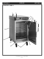
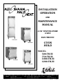
INSTALLATION
OPERATION
AND
MAINTENANCE
MANUAL
LOW TEMPERATURE
OVEN
ELECTRONIC
1200-TH/III
1000-TH/III
COOK
HOLD
MODEL:
500-TH/III
750-TH/III
1000-TH/III
1200-TH/III
750-TH/III
500-TH/III
W 1 6 4 N 9 2 2 1 W a t e r S t r e e t • P.O. Box 450 • Menomonee Falls, Wisconsin 53052-0450 USA
PHONE: 262.251.3800
FAX: 262.251.7067 • 800.329.8744 U.S.A. ONLY
WEBSITE:
800.558-8744 USA/CANADA
262.251.1907 INTERNATIONAL
www.alto-shaam.com
PRINTED IN U.S.A.
#8311 • 3/2005
INDEX
Section 1 — Installation
Unpacking and Setup . . . . . . . . . . . . . . . . . . . . . . . . . . . . . . . . . . . . . . 1
Oven Characteristics . . . . . . . . . . . . . . . . . . . . . . . . . . . . . . . . . . . . . . 1
Heat Recovery . . . . . . . . . . . . . . . . . . . . . . . . . . . . . . . . . . . . . . . . . . . 1
HACCP & Kitchen Management Software . . . . . . . . . . . . . . . . . . . . . . . 1
Electrical Installation . . . . . . . . . . . . . . . . . . . . . . . . . . . . . . . . . . . . . . 1
Stacking Mounting Instructions . . . . . . . . . . . . . . . . . . . . . . . . . . . . . 2-4
Start-Up . . . . . . . . . . . . . . . . . . . . . . . . . . . . . . . . . . . . . . . . . . . . . . . 5
Options and Accessories . . . . . . . . . . . . . . . . . . . . . . . . . . . . . . . . . . . . 5
1200-TH/III Installation Requirements. . . . . . . . . . . . . . . . . . . . . . . . . . 5
Photograph - Rear Panel of Single Oven . . . . . . . . . . . . . . . . . . . . . . . . 6
Section 2 — Controls
1200-TH/III Oven Control • Example .
Control Features . . . . . . . . . . . . . . .
Audible Signals . . . . . . . . . . . . . . . .
Operating Features and Functions . . .
Cook by Time . . . . . . . . . . . . . . . . .
Cook by Probe . . . . . . . . . . . . . . . . .
Preset Menu Key Programming . . . . .
Cook Using Preset Menu Keys. . . . . .
.
.
.
.
.
.
.
.
.
.
.
.
.
.
.
.
.
.
.
.
.
.
.
.
.
.
.
.
.
.
.
.
.
.
.
.
.
.
.
.
.
.
.
.
.
.
.
.
.
.
.
.
.
.
.
.
.
.
.
.
.
.
.
.
.
.
.
.
.
.
.
.
.
.
.
.
.
.
.
.
.
.
.
.
.
.
.
.
.
.
.
.
.
.
.
.
.
.
.
.
.
.
.
.
.
.
.
.
.
.
.
.
.
.
.
.
.
.
.
.
.
.
.
.
.
.
.
.
.
.
.
.
.
.
.
.
.
.
.
.
.
.
.
.
.
.
.
.
.
.
.
.
.
.
.
.
.
.
.
.
.
.
.
.
.
.
.
.
.
.
.
.
.
.
.
.
.
.
.
.
.
.
.
.
.
.
.
.
.
.
.
.
.
.
.
.
.
.
.
.
.6
.7
.8
.8
.9
10
11
12
Section 3 — Care and Cleaning
Clean the Oven Daily . . . . .
Clean the Probes Daily . . . .
Clean the Door Vents . . . . .
Check the Cooling Fan . . . .
Check Overall Condition . . .
.
.
.
.
.
.
.
.
.
.
.
.
.
.
.
.
.
.
.
.
.
.
.
.
.
.
.
.
.
.
.
.
.
.
.
.
.
.
.
.
.
.
.
.
.
.
.
.
.
.
.
.
.
.
.
.
.
.
.
.
.
.
.
.
.
.
.
.
.
.
.
.
.
.
.
.
.
.
.
.
.
.
.
.
.
.
.
.
.
.
.
.
.
.
.
.
.
.
.
.
.
.
.
.
.
.
.
.
.
.
.
.
.
.
.
.
.
.
.
.
.
.
.
.
.
.
.
.
.
.
.
.
.
.
.
.
.
.
.
.
.
.
.
.
.
.
.
.
.
.
.
.
.
.
.
.
.
.
.
.
13
13
13
13
13
Section 4 — User Options
Preset Keys Lock/Unlock . . .
Control Panel Lock/Unlock . .
Fahrenheit/Celsius Selection .
Beeper Volume Selection . . .
.
.
.
.
.
.
.
.
.
.
.
.
.
.
.
.
.
.
.
.
.
.
.
.
.
.
.
.
.
.
.
.
.
.
.
.
.
.
.
.
.
.
.
.
.
.
.
.
.
.
.
.
.
.
.
.
.
.
.
.
.
.
.
.
.
.
.
.
.
.
.
.
.
.
.
.
.
.
.
.
.
.
.
.
.
.
.
.
.
.
.
.
.
.
.
.
.
.
.
.
.
.
.
.
.
.
.
.
.
.
.
.
.
.
.
.
.
.
.
.
.
.
.
.
14
14
14
14
Section 5 — Service
Drip Tray Replacement . . . . . . . . . . . . . . . . . . . . . . . . . . . . . . . . . . . . 15
Service View 1 . . . . . . . . . . . . . . . . . . . . . . . . . . . . . . . . . . . . . . . . . . 16
Service View 1 Parts List . . . . . . . . . . . . . . . . . . . . . . . . . . . . . . . . . . 17
Cable Heating Service Kits . . . . . . . . . . . . . . . . . . . . . . . . . . . . . . . . . 17
Service View 2 - Electronic Components . . . . . . . . . . . . . . . . . . . . . . . 18
Service View 2 Parts List - Electronic Components . . . . . . . . . . . . . . . . 19
Trouble Shooting - Error Codes . . . . . . . . . . . . . . . . . . . . . . . . . . . . . . 20
Trouble Shooting - No Power . . . . . . . . . . . . . . . . . . . . . . . . . . . . . . . 21
Trouble Shooting - Unit not Heating . . . . . . . . . . . . . . . . . . . . . . . . . . 21
Trouble Shooting - How to Test Sensors and Probes. . . . . . . . . . . . . . . 21
Wiring Diagrams . . . . . . . . . . . . . . . . . . . . . . . . . . . . . . . . . . . . . . 22-26
Transportation Damage and Claims . . . . . . . . . . . . . . . . . . . . . . . . . . . . . 27
Warranty . . . . . . . . . . . . . . . . . . . . . . . . . . . . . . . . . . . . . . . . . . . . . . . . 27
#8311 O&C MANUAL•TH/III FAMILY
INDEX
SECTION 1
I N S TA L L AT I O N
Unpacking and Setup
The Alto-Shaam Cook and Hold
oven has been thoroughly tested,
checked for calibration, and inspected
to insure only the highest quality unit is
provided. When you receive your
cabinet, check for any possible shipping
damage and report it at once to the
delivering carrier. See Transportation
®
SECTION 1
HACCP & Kitchen Management
Software
®
This electronic
Cook/Hold oven is
equipped with a HACCP/Kitchen Management
interface for connection to a PC. It also has the
capability of being connected to the internet via a
Gateway device. This can provide temperature
recording data as well as setup and diagnostic
information which can be used for HACCP.
Damage & Claims section.
The cabinet, complete with unattached items and
accessories, may be delivered in one or more packages.
Save all the information and instructions packed
inside the cabinet. Complete and return the warranty
card to the factory as soon as possible to insure prompt
service in the event of a warranty parts and labor claim.
Electrical Installation
An identification tag is permanently mounted on the
cabinet. Make certain the model number and marked
electrical ratings match your order. Note the serial
number for your records.
Casters or legs, whether standard or optional, must
be installed on the oven before use. For the best
service, the oven should be installed level. The oven
should not be installed in any area where it may be
affected by steam, grease, dripping water, high
temperatures or any other severely adverse conditions.
Single compartment electronic Cook and Hold ovens
can be stacked with an identical oven. The 750-TH/III
can also be stacked with a 767-SK/III smoker. In order
to maintain parameters set for Demko Certification, the
full perimeter bumper must be ordered and installed on
the lower oven.
NOTE: Any claims for warranty must include the
full model number and serial number of
the cabinet.
Oven Characteristics
The cabinet is equipped with a special, low-heatdensity, heating cable. Through the Halo Heat ®
concept, the heating cable is mounted against the walls
of the cooking and holding compartment to provide an
evenly applied heat source, controlled by an oven
sensor. The design and operational characteristics of
the unit eliminate the need for a moisture pan or a heat
circulating fan. Through even heat application, the
food product is cooked evenly and capable of being
held for longer time periods. The unit must be installed
in a location that will permit the equipment to function
for its intended purpose and allow adequate access for
proper cleaning and maintenance.
Heat Recovery
The patented SureTemp™ heat recovery system in
this oven reacts immediately to compensate for any loss
of heat whenever the door is opened. If the door
remains open for more than three minutes, the solid
state electronic control will sound three rapid beeps
every ten seconds until the door is closed.
If necessary, a proper receptacle or outlet
configuration, as required for the individual equipment
model, must be installed by a licensed electrician in
accordance with applicable, local electrical codes.
The oven must be grounded in accordance with
requirement of the National Electrical Code or
applicable local codes.
Permanent wiring for all ovens
must be installed by a licensed
electrician in accordance with
applicable, local electrical codes.
The main power switch is located at the back of the
oven. After wiring and power connection has been
completed, turn the main power switch to the “ON”
position. This switch can be left “ON” for daily use, but
should be turned “OFF” when cleaning or performing
maintenance or repairs to the unit.
Remember to position the oven so that the
power supply cord is easily accessible in case of
an emergency.
For 230V units: To prevent an electrical shock
hazard between the appliance and other appliances
or metal parts in close vicinity, an equalization-bonding
stud is provided. An equalization bonding lead must
be connected to this stud and the other appliances /
metal parts to provide sufficient protection against
potential difference. The terminal is marked with the
following symbol.
#8311 O&C MANUAL•TH/III FAMILY
PG. 1
SECTION 1
I N S TA L L AT I O N
SECTION 1
Stacking Mounting Instructions
Using Stacking Platform from
Kit #16222 or 16237
to provide carving shelf:
it
7K
.
No
22
162
for
or
3
162
ing
lf
ng
vi
car
she
1. Remove the three screws in the top plate at the front of
the cabinet.
ck
sta
2. Remove the three screws in the back plate near the top
of the cabinet.
Step 2
Step 1
II
H/I III
T
/
500 0-TH
5
7
or
3. Position the stacking platform on top of the unit with
the flange in front, aligning the holes in the platform
over the holes in the cabinet.
4. Reinstall the cabinet screws removed in steps 1 and 2
through the platform holes to attach it to the cabinet,
front and back.
5. Place the carvery shelf on the stacking platform.
Stacking Configurations
Configuration
Stacking Assembly
1000-TH/III OVER 1000-TH/III • 1000-TH/III OVER 1000-S
750-TH/III OVER 750-TH/III • 750-TH/III OVER 767-SK/III
500-TH/III OVER 500-TH/III • 500-TH/III OVER 500-S
5000811
1000-S OVER 100-TH/III
750-TH/III OVER OR UNDER 750-S
500-S OVER 500-TH/III
5001359
TM OVER 500-S or 500-TH/III
BCS OVER 750-S or 750-TH/III
16237
16222
#8311 O&C MANUAL•TH/III FAMILY
PG. 2
SECTION 1
I N S TA L L AT I O N
SECTION 1
Stacking Mounting Instructions
STACKING PLATE INSTALLATION
Kit #5000811
1. Measure the length and width of the top surface of the
cabinet to be positioned at the bottom of the stacking
equipment combination. Add 1/8-inch to both the
length and the width dimension.
2. Turn the cabinet to be placed at the top of the stacking
combination upside down so that the top surface is on
the floor.
Stacking
Plate
h
pt
De
3. Place the four (4) stacking plates at each corner of the
cabinet. Position the plates with the upright flange
pointing up and to the outside of the cabinet. Align the
holes in the stacking plates with the predrilled holes in
the bottom of the cabinet using both the length and
width dimensions obtained in step 1.
Wi
4. When the correct alignment has been achieved, loosely
fasten each stacking plate with four (4) screws provided
in the stacking kit. DO NOT TIGHTEN SECURELY
since minor adjustments may be necessary.
dth
5. Stack the cabinets and make any necessary minor
adjustments to the stacking plates. When properly
aligned, the door on the top cabinet should be flush
with the door on the bottom cabinet.
6. When proper alignment has been made, remove the
top cabinet from the stacking combination. Firmly
secure all four stacking plates by individually removing
each screw and reattaching it in combination with one
of the square washers provided in the stacking kit.
Steps 3 and 4
above
#8311 O&C MANUAL•TH/III FAMILY
PG. 3
SECTION 1
I N S TA L L AT I O N
SECTION 1
Stacking Mounting Instructions
STACKING PLATE INSTALLATION
Kit #5001359
1. Measure the length and width of the top surface of the
cabinet to be positioned at the bottom of the stacking
equipment combination. Add 1/8-inch to both the length
and the width dimension.
2. Turn the cabinet to be placed at the top of the stacking
combination upside down so that the top surface is on the
floor. Remove the eight (8) bolts located at the front (door
side) and at the rear of the cabinet. Replace the bolts with
the eight (8) nylon plugs provided in the stacking kit
(RI-26196).
Stacking
Plate
h
pt
De
Wi
dth
3. Place the four (4) stacking plates at each corner of the
cabinet. Position the plates with the upright flange
pointing up and to the outside of the cabinet. Align the
holes in the stacking plates with the predrilled holes in the
bottom of the cabinet using both the length and width
dimensions obtained in step 1.
4. When the correct alignment has been achieved, loosely
fasten each stacking plate with four (4) screws provided in
the stacking kit. DO NOT TIGHTEN SECURELY since
minor adjustments may be necessary.
5. Stack the cabinets and make any necessary minor
adjustments to the stacking plates. When properly aligned,
the door on the top cabinet should be flush with the door
on the bottom cabinet.
6. When proper alignment has been made, remove the top
cabinet from the stacking combination. Firmly secure all
four stacking plates by individually removing each screw
and reattaching it in combination with one of the square
washers provided in the stacking kit.
Step 2 above
Steps 3 and 4
above
#8311 O&C MANUAL•TH/III FAMILY
PG. 4
SECTION 1
I N S TA L L AT I O N
Start-Up
SECTION 1
OPTIONS & ACCESSORIES
1. The unit should be installed level and must not be
installed in any area where it may be affected by
steam, grease, dripping water, high temperatures,
or any other severely adverse conditions.
2. Minimum clearances are required for proper
air ventilation including 3-inches (76mm) at the
back, 2-inches (51mm) at the top, and
1-inch (25mm) at both sides. On site venting for
proper airflow must also be provided for built-in
counter installations.
3. Before operating the oven, clean both the
interior and exterior of the unit with a damp cloth
and any good commercial detergent at the
recommended strength. Rinse surfaces by wiping
with a sponge and clean warm water to remove all
detergent residue. Wipe dry with a clean cloth or
air dry.
4. Wipe dry door gaskets and control panel
with a soft, clean cloth.
5. Clean and install the oven side racks, oven
shelves, and external drip tray. Shelves are
installed with curved edge toward the back of the
oven. Insert the drip pan on the interior bottom
surface of the oven.
6. Before operating the unit with product, become
familiar with the operation of the controls. Read
this manual and operate the various control
functions.
At no time should the oven
interior or exterior be steam
cleaned, hosed down, or flooded
with water or liquid solution. Do
not use water jet to clean. Severe
damage or electrical hazard could
result voiding the warranty.
Bumper, rubber, full perimeter w/casters
— 1000-TH/III . . . . . . . . . . . . . . . . . . . . . . . . . . . . . . . .44091
— 750-TH/III . . . . . . . . . . . . . . . . . . . . . . . . . . . . . . . . .44090
— 500-TH/III . . . . . . . . . . . . . . . . . . . . . . . . . . . . . . . . .44089
Carving Holders
— Prime Rib Holder . . . . . . . . . . . . . . . . . . . . . . . . . . .HL-2635
— Ship Round Holder w/pan . . . . . . . . . . . . . . . . . . . . . . .4459
Carving Shelf Mounting Adapter
— 750-TH/III . . . . . . . . . . . . . . . . . . . . . . . . . . . . . . . . .16237
— 500-TH/III . . . . . . . . . . . . . . . . . . . . . . . . . . . . . . . . .16222
Casters, 3" (76mm) . . . . . . . . . . . . . . . . . . . . . . . . . . . . .14227
Casters, 5" (127mm) . . . . . . . . . . . . . . . . . . . . . . . . . . . . .4007
Drip Pan, Extra Deep
— 750, 1000, 1200-TH/III . . . . . . . . . . . . . . . . . . . . . . . .1115
Drip Pan, Standard, w/drain and screen
— 1000, 1200-TH/III . . . . . . . . . . . . . . . . . . . . . . . . . . .14824
— 750-TH/III . . . . . . . . . . . . . . . . . . . . . . . . . . . . . . . . .14831
— 500-TH/III . . . . . . . . . . . . . . . . . . . . . . . . . . . . . . . . .14813
Door Lock w/key . . . . . . . . . . . . . . . . . . . . . . . . . . . .LK-22567
Legs, 6" (152mm) — 500, 750, 1000-TH/III . . . . . . . . . . .5205
Leg Kit Option — 1200-TH/III ONLY . . . . . . . . . . . . . . . . .44093
Shelves, S/S Rib Rack
— 1000, 1200-TH/III . . . . . . . . . . . . . . . . . . . . . . . . .SH-2773
— 750-TH/III . . . . . . . . . . . . . . . . . . . . . . . . . . . . . . .SH-2743
Shelves, S/S Flat Wire
— 1000, 1200-TH/III . . . . . . . . . . . . . . . . . . . . . . . . .SH-2325
— 750-TH/III . . . . . . . . . . . . . . . . . . . . . . . . . . . . . . .SH-2324
— 500-TH/III . . . . . . . . . . . . . . . . . . . . . . . . . . . . . . .SH-2326
Wire pan grid
— 1200, 1000, 750-TH/III . . . . . . . . . . . . . . . . . . . . .PN-2115
➥18" X 26" (457mm x 660mm) Insert
Stacking Adapter
1000-TH/III OVER 1000-TH/III • 1000-TH/III OVER 1000-S . . . . .5000811
750-TH/III OVER 750-TH/III • 750-TH/III OVER 767-SK/III
500-TH/III OVER 500-TH/III • 500-TH/III OVER 500-S
1000-S OVER 100-TH/III, 750-TH/III OVER OR UNDER 750-S, . . . .5001359
500-S OVER 500-TH/III
This wall-friendly full perimeter bumper is now offered
as standard on the 1200-TH/III cook/hold oven.
It is offered as an option for the Models 500, 750, and
1000-TH/III cook/hold ovens.
1200-TH/III Installation Requirements
( Double Compartment Oven) :
Tether Attachment for Permanent Wiring:
A) A permanently connected appliance, with casters attached, must be tethered
Holes for Lanyard Tether Cord Attachment
to the building structure, in two places, to limit movement of the appliance
without depending on or transmitting stress to the electrical conduit.
B) A hole on each side of the rear center grill, lower flange, is provided for attaching two tether cables. The other end of
each should be anchored to the wall structure with hardware sufficient to withstand 200 pound pull. (1/16" aircraft
cable and 1/4" x 2" lag bolts are recommended.)
C) The appliance shall be installed using flexible conduit, with the system meeting requirements of National Electric Code
for appliance rating. International units should meet national or country codes.
Cord Connection for Semi-Permanent Installation:
A) Use UL listed (or appropriate country installation) grounding type plug with integral cord grip that is rated for 250
Volts, 30 Amperes, Single Phase, and 10 gauge cord with insulation system meeting codes for installation.
B) Conductors of supply cord must be connected to terminal block marked L1 and L2 with greater length
for ground lead to center terminal marked GND.
#8311 O&C MANUAL•TH/III FAMILY
PG. 5
SECTION 1
I N S TA L L AT I O N
SECTION 1
On/Off
Electrical
Power Switch
Hi-Limit
Button
Serial
Number
Tag
Rating & Certification
Identification Tag
Model 1000-TH/III
Single Oven
Back of Unit
Hi-Limit Reset Button
1200-TH/III Double
Compartment Oven
SECTION 2
CONTROLS
SECTION 2
Double Compartment Oven
1200-TH/III Control
This model has two O N /O FF Key
controls, one to control the top
cooking cavity, one to control the
bottom cooking cavity.
Double Oven Control
Each compartment is controlled
and programmed separately.
#8311 O&C MANUAL•TH/III FAMILY
PG. 6
SECTION 2
CONTROLS
SECTION 2
PRESETS
A
Single Oven Control
B
C
D
E
F
G
H
I
CANCEL
CONTROL FEATURES
1. O N /O FF Key
9. LED Display
The O N /O FF control system key operates the
functions of the control panel. If there is any
power loss during operation, the O N /O FF indicator
light will flash. To clear, push key and release.
2. C OOK Key — Temperature range 200° to 325°F
(93° to 162°C)
Used to select cooking mode and to review the
cook temperature setting.
3. T IME Key — Maximum time 24 hours
4. P ROBE Key — Temperature range 50° to 195°F
(10° to 91°C)
Used to select internal product probe temperature
mode and to review probe temperature setting.
5. H OLD Key — Temperature range 60° to 205°F
(15° to 96°C)
Used to select food holding mode and to review set
holding temperature.
6. Lock Indicator
When illuminated, this symbol indicates settings
used in the cooking sequence are locked and
cannot be changed.
7. Halo Heat Indicator
When the oven is preheating, the Halo Heat
indicator will illuminate during preheating and
remain steady until the oven reaches the set
cooking temperature. When the temperature has
stabilized, the indicator will illuminate periodically as the oven calls for heat.
Illuminates until the oven is preheated.
10. Ready Indicator Light
Illuminates when the oven has finished preheating.
11. U P and D OWN A RROWS
Used to select cook time and to review set time.
8. Oven Preheat Light
Indicates interior oven air temperature, internal
product probe temperature, time, or when used
in conjunction with other keys, will review
original cooking, holding and probe temperature
settings. The display will also indicate various
programming and diagnostic information.
Used to increase or decrease set time, including
cooking, holding and probe temperature settings.
12. S TART Key
Used to initiate a selected mode sequence when
pressed and released. You may stop any mode
of operation by pressing and holding the S TART
Key until you hear a beep.
13. Green Indicator Lights
Located within each function key, the green
light functions as an operator prompt indicating
additional operator action is required and also
identifies current mode of operation.
14. Amber Indicator Lights
Located below the C OOK , T IME , P ROBE and H OLD
Keys, these indicators will illuminate to identify
the current mode of operation and allows the
operator to identify the information currently
shown in the LED display.
15. P RESET Program Keys
Provides memory storage and operation of up to
eight operator set cooking programs for specific
products (A thru H). I enables locking abilities.
16. C ANCEL Key
Used to erase a program from memory storage.
I M P O R TA N T
Do not use the oven if the controls are not properly functioning. Refer to the Trouble Shooting Guide
located in this manual or call an authorized service technician.
#8311 O&C MANUAL•TH/III FAMILY
PG. 7
SECTION 2
C O N T R O L F E AT U R E S
SECTION 2
AUDIBLE SIGNALS
OVEN BEEPING is used to indicate a Y ES or N O response to operator input.
Beeps also indicate mode C HANGES and E RROR conditions.
One brief beep indicates a Y ES (enabled) response to the information entered into the control.
Two brief beeps indicate a N O (disabled) response to the information entered into the control.
A beep that lasts for one second indicates an oven mode T RANSITION . Example: Preheat to Ready-Start.
Three brief beeps indicate the oven is in the R EADY mode for product loading and S TART - UP .
Four brief beeps indicate an existing F AULT condition. Refer to the Trouble Shooting section of this manual.
Beeper volume can be changed. With the control in the O FF mode, press and hold the D OWN A RROW Key. After 4 seconds,
the display will exhibit one of the 4 volume levels (0 being O FF or the lowest, and 3 being the highest). After each change, the
button must be released and the display must clear before the procedure can be repeated to select a different volume level.
O P E R AT I N G F E AT U R E S & F U N C T I O N S
Turn the Oven Control Panel Off:
Press and hold the ON/OFF Key for three seconds. Oven will
beep. The ON/OFF indicator light will go out.
Stop an Operation:
Press and hold the START Key for several seconds until the control
beeps, indicating the operation has been cancelled. The oven will
remain in a power-on state.
Arrow Keys:
Cook, Hold and Probe Temperature set points can be adjusted
by 1° when pressing the ARROW Keys. To change a set point more
rapidly, press and hold the ARROW Key along with the key for the
temperature function, and the temperature changes in steps of 10°F
or 5°C.
The Time setting is adjusted in increments of one minute by pressing
the ARROW Keys. To make adjustment in steps of ten minutes, press
and hold the TIME Key and ARROW Key at the same time.
Probe Usage:
When the probe is left in the probe bracket, the LED temperature
display will indicate the ambient air temperature inside the oven. To
use the probe for cooking remove it from the bracket and wipe the
full length of the metal probe with a disposable alcohol pad to clean
and sanitize before using.
Dis play High/Low Probe Temperatures:
To observe the recorded maximum or minimum probe
temperature during a cooking program press the
following keys:
Highest Temperature: Press PROBE Key and UP ARROW
Key at same time.
Lowest Temperature: Press PROBE Key and DOWN ARROW
Key at same time.
Halo Heat Indicator:
When the oven is preheating the Halo Heat indicator light
will remain illuminated until it reaches the set cook
temperature. Once the temperature has stabilized, this
indicator will illuminate periodically as the oven calls for heat.
Green and Amber Indicators:
Each program key includes a green light which indicates a
requirement for additional programming by the operator or
the current operational state of the oven.
The COOK, TIME, PROBE, and HOLD keys include an amber
indicator light to identify the information being displayed.
Green
SPECIAL ATTENTION:
When preheating, the temperature of the product
probe reaches the air temperature inside the oven.
Always allow the product probe temperature to
decrease to the internal temperature of the raw product by inserting the probe and waiting one full minute
before pressing the start button. A false reading of
the internal temperature of the product may cause
the oven to default to a holding temperature.
Only the tip of the probe senses the internal product temperature;
therefore, it is important the tip be placed correctly in the product for
internal temperature accuracy. Push the probe tip halfway into the
product, positioning the tip at the center of the food mass. When
inserting the probe into solid foods such as meat roast or poultry
breasts, push the probe in from a straight downward position or in
from the side to the center position. If placing into a semi-liquid or
liquid product, the probe cable must be secured to keep the probe
positioned properly. Do not let the probe tip touch the edges, bottom or side of a container. Tape the probe cable to the lip or edge
of the container.
●
TIME
Amber
Power Fail Detect:
If the power were to fail for any reason while heating, the
control will retain, in memory, the programmed operating
conditions. When power is restored, the control will resume
operating from the point where it was interrupted and the
ON/OFF indicator light will flash, indicating that such an event
did occur. The operator can turn off the flashing light by
pressing the ON/OFF key.
If such an event has occurred, it is strongly
recommended that you ensure the food is safe for
consumption according to local health regulations.
#8311 O&C MANUAL•TH/III FAMILY
PG. 8
SECTION 2
C O N T R O L O P E R AT I O N
Cook by Time:
ON/OFF
IS THE MAIN ELECTRICAL POWER SWITCH ON ?
SECTION 2
HELPFUL HINT
To avoid prolonged
Press and release control O N /O FF key.
preheat times between
• The green indicator light on the O N /O FF key will illuminate.
loads, leave the
• The oven will beep for one second.
oven in the
• The oven will begin operating in the hold mode.
hold mode.
• The amber hold indicator will illuminate.
• The previously set hold temperature will be displayed.
Press the H OLD Key.
➥ To change the hold temperature, press the U P or D OWN A RROW Keys.
Note: I f t h e o v e n i s b e i n g u s e d f o r h o t f o o d h o l d i n g o n l y , a d j u s t t h e
set holding temperature. Do not press the C O O K , T I M E , or P R O B E Keys.
Press C OOK Key to preheat.
• The green indicator light on the C OOK Key will illuminate.
• Last set cooking temperature will be displayed.
➥ To change the cook temperature, press the U P or D OWN A RROW Keys.
• The green indicator light on the T IME Key and on the P ROBE Key alternately flash.
Press T IME Key.
Cold food for
• The green indicator light on the T IME Key will illuminate.
rethermalization
or
• Last set time is displayed.
reheating must never
➥ To change the cook time, press the U P or D OWN A RROW Keys.
be added to the
• The green indicator light on the T IME Key will illuminate.
oven while hot food is
• Halo Heat and Pre-Heat indicator will illuminate.
being held.
➥ The oven is automatically programmed to preheat to the cook
temperature.
• The oven will beep when preheated and the preheat indicator light will go out.
• Both the Ready and Start indicator lights will flash.
➥ The set cook temperature will be maintained by the oven and appear in the display
while in the ready/start mode.
Load the food inside oven and close the oven door.
Note: The oven will beep 3 times every 25 seconds until the oven is loaded and the S TART
Key pressed.
START
Press and release S TART key.
COOK
• The oven will beep.
• The green indicators for power, cook, time, and start will illuminate.
• The display will alternate between showing the set cook temperature and the remaining time.
HOLD
• The oven will beep at the end of the timed cooking cycle.
• The green indicator for cook will remain illuminated.
• The display will alternate between showing the set hold temperature and the amount of time
the product has remained in the holding mode.
• The Ready indicator light will illuminate after 2 hours in the hold mode.
Note: The ready indicator does not necessarily indicate a product-ready state. For best
results, the product must remain in the oven at the set holding temperature for the
minimum number of hours indicated in the individual cooking instructions.
• The oven will remain operating in the hold mode until the control O N /O FF Key is pressed.
#8311 O&C MANUAL•TH/III FAMILY
PG. 9
SECTION 2
Cook by Probe:
ON/OFF
C O N T R O L O P E R AT I O N
IS THE MAIN ELECTRICAL POWER SWITCH ON ?
Press and release control O N /O FF Key.
• The green indicator light on the O N /O FF key will illuminate.
• The oven will beep for one second.
• The oven will begin operating in the hold mode.
• The amber hold indicator will illuminate.
• The previously set hold temperature will be displayed.
Press the H OLD Key.
➥ To change the hold temperature, press the U P or D OWN A RROW Keys.
SECTION 2
Cold food for
rethermalization
or reheating
must never be
added to the
oven
while hot food is
being held.
Note: I f t h e o v e n i s b e i n g u s e d f o r h o t f o o d h o l d i n g o n l y , a d j u s t t h e s e t h o l d i n g
temperature. Do not press the C OOK , T IME , or P ROBE keys.
Press C OOK Key to preheat.
• The green indicator light on the C OOK Key will illuminate.
• Last set cooking temperature will be displayed.
➥ To change the cook temperature, press the U P or D OWN A RROW Keys.
• The green indicator light on the T IME Key and on the P ROBE Key alternately flash.
Press P ROBE Key.
• The green indicator light on the P ROBE Key will illuminate.
• Last set internal product temperature is displayed.
➥ To change the internal product temperature, press the U P or D OWN A RROW Keys.
• The green indicator light on the P ROBE Key will illuminate.
• Halo Heat and Pre-Heat indicator will illuminate.
➥ The oven is automatically programmed to preheat to the cook temperature.
• The oven will beep when preheated and the preheat indicator extinguished.
• Both the Ready and Start indicator lights will flash.
➥ The set cook temperature will be maintained by the oven and appear in the display
while in the ready/start mode.
Load the food inside oven. Remove probe from its bracket, wipe the probe tip
with a disposable alcohol pad and insert probe properly into the product. Close
the oven door.
Note: Oven will beep 3 times every 25 seconds until oven is loaded and S TART Key pressed.
START
Press and release S TART key.
COOK
• The oven will beep.
• The green indicators for power, cook, probe, and start will illuminate.
• The display will alternate between showing the probe temperature and the elapsed time.
HOLD
• The oven will beep when the set probe temperature has been reached.
• The green indicator for cook will remain illuminated.
• The display will alternate between showing the set hold temperature and the amount of time
the product has remained in the holding mode.
• Ready indicator light will illuminate after 2 hours in the hold mode.
Note: The ready indicator does not necessarily indicate a product-ready state. For best
results, the product must remain in the oven at the set holding temperature for the
minimum number of hours indicated in the individual cooking instructions.
• The oven will remain operating in the hold mode until the control O N /O FF Key is pressed.
#8311 O&C MANUAL•TH/III FAMILY
PG. 10
SECTION 2
C O N T R O L O P E R AT I O N
SECTION 2
Preset Menu Keys:
Alto-Shaam Cook and Hold ovens allow the operator to set up to eight cooking programs. Each cooking program can be preset in any program mode to cook by time or internal product temperature. Cooking programs
are recalled and stored using the PRESET Keys labeled "A through H." These keys, along with the key labeled "I"
share additional functions described in the "User Options" section of this manual.
Programming a Cooking Program
Prior to this procedure, make sure the oven is “OFF”. Select the food product to be programmed.
Press and release control ON/OFF key. The oven will beep for one second and power to the unit
will be indicated by an illuminated green indicator light located in the upper left corner of the
ON/OFF key. The oven will begin operating in the hold mode. The amber hold indicator will be
illuminated and the last set hold temperature will be displayed.
ON/OFF
Press H OLD Key. To change the hold temperature, press the U P or D OWN
A RROW Keys.
Press C OOK Key. Oven preheat indicator will illuminate and the last set cooking temperature
is displayed. To change the cook temperature, press the U P or D OWN A RROW Keys.
To cook by time — press the T IME Key. Last set cooking time is displayed.
To change the set time, press the U P or D OWN A RROW Keys. The green Time
indicator will illuminate.
—
or —
To cook by probe — press the PROBE Key. Last set internal product temperature is displayed.
To change the set temperature, press the UP or DOWN ARROW Keys. The green Probe indicator
will illuminate.
The oven preheat indicator will illuminate. Oven is now in the preheat mode and is
automatically programmed to preheat to the cook temperature.
PRESETS
A
Select a letter code for the product programmed by the previous steps. Press and hold the
selected PRESET key until you hear a brief, four second beep. The letter key program indicator
light will illuminate and the product programmed is now stored in memory for the specific letter
key pressed. Additional programs can be stored in the remaining PRESET Keys if not previously
programmed.
Note: The last PRESET Key used will be the oven cooking run sequence for the next product
to be programmed. Settings can be manually changed for the next product and an alternate
pre-programmed letter key selected.
Erasing a Cooking Program
To erase a program, the oven must be in either the power-up hold mode or in the preheat mode. The oven
cannot be running a Preset Menu program.
When the oven is in the power-up hold mode or in the preheat mode, press and hold both the CANCEL Key and
the appropriate letter PRESET Key to be erased. The oven will beep in approximately four seconds and the
program's indicator light will go out to indicate the program has been erased.
I M P O R TA N T
After programming a specific product into memory in a programmable preset key,
it is very important to make a written permanent record of the product and the
program letter assigned. Menu card (PE-23384) is provided for this purpose.
#8311 O&C MANUAL•TH/III FAMILY
PG. 11
SECTION 2
C O N T R O L O P E R AT I O N
SECTION 2
Cook Using Preset Menu Keys:
Press and release control O N /O FF Key.
• The green indicator light on the O N /O FF key will illuminate.
ON/OFF
• The oven will beep for one second.
• The oven will begin operating in the hold mode.
• The amber hold indicator will illuminate.
• The previously set hold temperature will be displayed.
• P RESET Keys with stored cooking programs will have green indicator illuminated.
PRESETS
A
Press Desired P RESET Key (A through H)
• Halo Heat and Pre-Heat indicator will illuminate.
➥ The oven is automatically programmed to preheat to the cook temperature programmed.
• The oven will beep when preheated and the preheat indicator will go out.
• Both the Ready and Start indicator lights will flash.
➥ The set cook temperature will be maintained by the oven and appear in the display
while in the ready/start mode.
Load the food inside oven. If cooking by probe, remove probe from its bracket,
wipe the probe tip with a disposable alcohol pad and insert probe properly into
product. Close the oven door.
Note: The oven will beep 3 times every 25 seconds until the oven is loaded and the
S TART key pressed.
Press and release S TART Key.
START
COOK
• The oven will beep.
• The green indicators for power, cook, probe or time, and start will illuminate.
• If programmed to cook by time, the display will alternate between showing the set cook
temperature and the time remaining.
• If programmed to cook by probe, the display will alternate between showing the set cook
temperature and the elapsed time.
HOLD
• The oven will beep when the set probe temperature has been reached or set time has elapsed.
• The green indicator for cook will remain illuminated.
• The display will alternate between showing the set hold temperature and the
amount of time the product has remained in the holding mode.
• The Ready indicator light will illuminate after 2 hours in the hold mode.
Note: The ready indicator does not necessary indicate a product-ready state. For best
results, the product must remain in the oven at the set holding temperature for the
minimum number of hours indicated in the individual cooking instructions.
• The oven will remain operating in the hold mode until the control O N /O FF Key is pressed.
#8311 O&C MANUAL•TH/III FAMILY
PG. 12
SECTION 3
CARE AND CLEANING
SECTION 3
Under normal operating conditions, this oven will provide you with long and troublefree service. There is no preventative maintenance required, however, the following
guidelines will maximize the potential life and trouble-free operation of this oven.
Clean the Oven Daily
MAKE CERTAIN
THE UNIT IS
DISCONNECTED
FROM THE ELECTRICAL POWER
SOURCE BEFORE
CLEANING
The cleanliness and appearance of this equipment will contribute considerably
to operating efficiency and savory, appetizing food. Good equipment that is kept clean works
better and lasts longer.
1. Switch electrical power switch located at the back of the oven to the "OFF" position.
Let unit cool.
2. Remove all detachable items such as wire shelves, side racks, and drip pan. Clean these
items separately.
3. Wipe the interior metal surfaces of the oven with a paper towel to remove loose food
debris.
4. Clean interior with a damp cloth or sponge and any good commercial detergent at the
recommended strength.
5. Spray heavily soiled areas with a water soluble degreaser and let stand for
10 minutes, then remove soil with a plastic scouring pad.
NOTE: Avoid the use of abrasive cleaning compounds, chloride based cleaners,
or cleaners containing quaternary salts. Never use hydrochloric acid
(muriatic acid) on stainless steel.
6. Wipe control panel, door vents, door handles, and door gaskets thoroughly
since these areas harbor food debris.
7. Rinse surfaces by wiping with sponge and clean warm water.
8. Remove excess water with sponge and wipe dry with a clean cloth or air dry.
Leave doors open until interior is completely dry. Replace side racks and shelves.
9. Wipe door gaskets and control panel dry with a clean, soft cloth.
10. Interior can be wiped with a sanitizing solution after cleaning and rinsing.
This solution must be approved for use on stainless steel food contact surfaces.
11. To help maintain the protective film coating on polished stainless steel, clean the exterior
of the cabinet with a cleaner recommended for stainless steel surfaces. Spray the cleaning
agent on a clean cloth and wipe with the grain of the stainless steel.
12. Clean any glass with a window cleaner.
Always follow appropriate state or local health (hygiene) regulations regarding all applicable
cleaning and sanitation requirements for food service equipment.
Clean the Probes Daily
Remove all food soil from probes. Wipe entire probe and cable assembly with warm
detergent solution and a clean cloth. Remove detergent by wiping each probe and
cable with clean rinse water and a cloth. Wipe probes and probe brackets with
disposable alcohol pad or sanitizing solution recommended for food contact
surfaces. Allow probe and cable to air dry in probe holding bracket.
Clean the Door Vents
Door vents need to be inspected and cleaned as required.
Check the Cooling Fan in the Oven Control Area
While the oven is warm, check that the cooling fan in the oven control area
is functioning. The fan is located at the back of the unit, toward the top.
Model 1200-TH/III has an additional ambient chamber fan located in the back,
centered between the top and bottom cavity. Both fans must be functioning
in order for the oven to work properly.
Check Overall Condition of the Oven Once a Month
Check for physical damage and loose screws. Correct any problems before
they begin to interfere with the operation of the oven.
#8311 O&C MANUAL•TH/III FAMILY
PG. 13
SECTION 4
USER OPTIONS
SECTION 4
Lock
Indicator
PRESETS
A
B
C
D
E
F
G
H
I
CANCEL
Preset
Lock
PRESET Keys Lock and Unlock
Control Panel Lock and Unlock
PRESET Keys A through H can be locked in order to
prevent storing, altering or erasing a program.
The control panel can be locked at any time in order to
prevent inadvertent or accidental setting changes.
To lock the PRESET Keys, press and hold the "I" Key
for four seconds. Oven will beep. Release the “I” key.
The green indicator on the "I" key will illuminate. Oven
PRESET Keys A through H are now locked.
To lock the control panel, press and hold the UP
ARROW Key and then press the ON/OFF Key.
You will hear a brief beep and the panel lock
indicator will illuminate. Release all keys. The oven's
control panel is now locked.
Note: Only the oven PRESET keys A through H are
affected by this lock-out in order to also allow the
oven to be used with the unprogrammed Cook,
Probe, or Hold modes.
To unlock the PRESET Keys, press and hold the CANCEL
Key along with the "I" Key for four seconds. You will
hear a brief beep. Release all keys. The green indicator
on the "I" key will extinguish. The oven preset keys are
now unlocked.
Note: The control panel is now fully locked
with the exception of the ON/OFF Key and ARROW
keys. You will be unable to turn the oven control
off at this point.
To unlock the control panel, press and hold the DOWN
ARROW Key and then press the ON/OFF Key. You will
hear two brief beeps and the panel lock indicator will extinguish. Release all keys. The panel is now unlocked and
ready for normal use.
Fahrenheit or Celsius Selection
Beeper Volume Selection
With the control in the off mode,
press and hold the UP ARROW Key.
After four seconds, the display will toggle
between Fahrenheit and Celsius. After each
change the button must be released. The
display must clear before the procedure can
be repeated.
With the control in the off mode,
press and hold the DOWN ARROW Key.
After 4 seconds, the display will show one
of the 4 volume levels (0 being OFF or the
lowest, and 3 being the highest). After
each change, the button must be released
and the display must clear before the procedure can be repeated to select a different
volume level.
#8311 O&C MANUAL•TH/III FAMILY
PG. 14
SECTION 5
S E RV I C E
SECTION 5
DRIP TRAY REPLACEMENT INSTRUCTIONS
LOW TEMPERATURE TH/III SERIES
COOKING & HOLDING OVENS
STANDARD DRIP PAN*
[BOTTOM OF OVEN INTERIOR • BELOW
SIDE-RACKS]
DRIP
TRAY*
WHEN MOUNTING
DRIP STRIP, SEAL
STRIP TO THE UNIT
WITH AN R.T.V.
SEALANT TO PREVENT
MOISTURE FROM
PENETRATING INTO
OVEN COMPARTMENT
DRIP
STRIP*
3: #8-32 X 1/2" SCREWS*
*SEE ALTO-SHAAM PARTS LIST FOR ALTO-SHAAM PART NUMBERS.
#8311 O&C MANUAL•TH/III FAMILY
PG. 15
SECTION 5
S E RV I C E
SECTION 5
SERVICE VIEW 1
O&C MANUAL #8311 • TH/III FAMILY
PG. 16
SECTION 5
S E RV I C E
S E R V I C E V I E W 1 • PA R T S
SECTION 5
MODELS
500-TH/III
750-TH/III
1000-TH/III
1200-TH/III
1. Top
1001434
1001443
1001027
1001027
2. Panel Overlay
PE-23658
PE-23659
PE-23660
PE-25376
3. Shelf, stainless steel wire, ea.
SH-2326
SH-2324
SH-2325
SH-2325
4. Side Rack, shelf, s/s, ea., 208-240V
Side Rack, Pan Slide, 230V ONLY
SR-2386
14978
SR-2303
14979
SR-2266
SR-2266
5. Probe Assembly
15892
15892
15892
15892
6. Door Vent Cover
13155
13155
13155
13155
7. Door Assembly
Slab, RH
Slab, LH
Window, RH
Window, LH
15848
15853
15855
15857
15429
15730
15433
15732
15415
15721
15879
15881
15415
15721
15879
15881
8. Door Gasket, ea.
GS-22950
GS-22951
GS-22952
GS-22952
9. Door Handle
Mounting Screws for Handle (4)
Mounting Screws for Latch (2)
HD-24171
SC-2073
SC-2071
HD-24171
SC-2073
SC-2071
HD-24171
SC-2073
SC-2071
HD-24171
SC-2073
SC-2071
10. Door Hinge, pair
Mounting Screws for Hinge (12)
HG-22338
SC-2072
HG-22338
SC-2072
HG-22338
SC-2072
HG-22338
SC-2072
11. Caster, 5" (127mm) swivel, ea.
Caster, 5" (127mm) rigid, ea.
Caster Mounting Screws
CS-2026
CS-2025
SC-2351
CS-2026
CS-2025
SC-2351
CS-2026
CS-2025
SC-2351
N/A
12. Drip Tray
14812
14392
14823
14949
13. Drip Pan
14813
14831
14824
14824
14. Bottom
14809
14386
14827
14153
15. Side, each
1570
1003349
1737
(UPPER) 1737
(LOWER) 1738
16. Casing Back, each
1560
13199
1736
1736 (2)
44089
44090
44091
CS-24875 (2)
CS-24874 (2)
CS-24875 (2)
CS-24874 (2)
CS-24875 (2)
CS-24874 (2)
Part Description
Service View 1
Bumper, rubber, full perimeter
(NOT SHOWN) INCLUDES:
Casters, 5" (127mm) swivel w/brake
Casters, 5" (127mm) rigid
PLUS BASE/RUBBER/FRAME/SUBASSEMBLY, SCREWS, ETC.
44092
INCLUDED
CS-24875 (2)
CS-24874 (2)
CABLE HEATING SERVICE KITS
MODELS
No. 4879
500-TH/III, 125V
includes:
CB-3045
CR-3226
IN-3488
BU-3105
BU-3106
ST-2439
NU-2215
SL-3063
TA-3540
MODELS
No. 4880
500-TH/III, 208-240V
includes:
Cable Heating Element . . . 112 feet
Ring Connector . . . . . . . . . . . . . 6
Insulation Corner . . . . . . . . 1 foot
Shoulder Bushing . . . . . . . . . . . 6
Cup Bushing . . . . . . . . . . . . . . . 6
Stud . . . . . . . . . . . . . . . . . . . . 6
Hex Nut . . . . . . . . . . . . . . . . . 12
Insulating Sleeve . . . . . . . . . . . . 6
Electrical Tape . . . . . . . . . . 1 roll
CB-3045
CR-3226
IN-3488
BU-3105
BU-3106
ST-2439
NU-2215
SL-3063
TA-3540
No. 4881
750, 1000 AND 1200-TH/III
(ONE KIT PER UNIT CAVITY)
MODELS
includes:
Cable Heating Element . . . 134 feet
Ring Connector . . . . . . . . . . . . . 4
Insulation Corner . . . . . . . . 1 foot
Shoulder Bushing . . . . . . . . . . . 4
Cup Bushing . . . . . . . . . . . . . . . 4
Stud . . . . . . . . . . . . . . . . . . . . 4
Hex Nut . . . . . . . . . . . . . . . . . . 8
Insulating Sleeve . . . . . . . . . . . . 4
Electrical Tape . . . . . . . . . . 1 roll
O&C MANUAL #8311 • TH/III FAMILY
PG. 17
CB-3045
CR-3226
IN-3488
BU-3105
BU-3106
ST-2439
NU-2215
SL-3063
TA-3540
Cable Heating Element . . . 210 feet
Ring Connector . . . . . . . . . . . . 12
Insulation Corner . . . . . . . . 1 foot
Shoulder Bushing. . . . . . . . . . . 12
Cup Bushing . . . . . . . . . . . . . . 12
Stud . . . . . . . . . . . . . . . . . . . 12
Hex Nut . . . . . . . . . . . . . . . . . 24
Insulating Sleeve . . . . . . . . . . . 12
Electrical Tape . . . . . . . . . . 1 roll
SECTION 5
S E RV I C E
SERVICE VIEW 2
SECTION 5
ELECTRONIC COMPONENTS
On/Off Electrical Power
Switch, 30 Amp
SW-33858
Hi-Limit Thermostat
TT-33476
Sensor T-Block
BA-33764
Fan
FA-3568
Beeper
BP-3567
(208/240V)
FA-3599
(120V)
T-Block
BK-3019
Relay
RL-33829
Ground Screw
SC-2190
Modular
Block Assembly
BK-33364
Power
Supply Board
BA-33554
Voltage
Monitor Board
BA-33764
Control
CC-34063
Control Panel Overlay
PE-23658 (500-TH/III)
PE-23659 (750-TH/III)
PE-23660 (1000-TH/III)
PE-25376 (1200-TH/III)
Unit Front
Model 750-TH/III
with top removed
Do not replace any electrical components without first disconnecting electrical power to the
unit by switching O FF electrical power at back of oven. A warning sign should be posted on the
panel indicating the oven is being serviced and that the power must remain O FF .
O&C MANUAL #8311 • TH/III FAMILY
PG. 18
SECTION 5
S E RV I C E
500-TH/III
750-TH/III
1000-TH/III
PART DESCRIPTION
1.
Fan Cord
Connector
2.
SECTION 5
1200-TH/III
CD-33338
CD-33338
CR-3596
Fan, 208/240V
Fan, 120V
Connector
FA-3568
FA-3599
FA-3568
FA-3574
CR-33509
3.
Fan Thermostat
Connector
TT-33255
TT-33255
CR-3849
4.
Circuit Breaker Switch
SW-33858
SW-3715
5.
Terminal Block
BK-3019
BK-3019
Terminal Block
BK-3023
6.
Beeper, Solid State
BP-3567
BP-3567
7.
Hi-Limit Thermostat
TT-33476
TT-33476
8.
Power Supply Board
BA-33554
BA-33554
9.
Voltage Monitor Board Assembly
BA-33764
BA-33764
10.
Sensor Terminal Block
BK-33546
BK-33546
11.
Modular Block Assembly
BK-33364
BK-33364
12.
Sensor, Air Temperature
SN-33540
SN-33540
13.
Switch Reed for Door
SW-33559
SW-33559
14.
Relay
Heat Sink Pad
RL-33829
HE-33926
RL-33829
HE-33926
15.
Cordset, 120V
Cordset, 208-240V
Cord
CD-33824
CD-3588
Cordset, 230V, 500-TH/III only
Cordset, 230V
Plug (UK and Hong Kong)
CD-3922
CD-33882
PG-33368
16.
Ground Screw
17.
Control
CD-3304
SC-2190
SC-2190
CC-34063
CC-34063
ELECTRONIC COMPONENTS
Do not replace any electrical components without first disconnecting electrical power
to the unit by the O N /O FF switch at the back of the oven. A sign indicating the oven is
being serviced and that the power must remain O FF should be posted on the panel.
#8311 O&C MANUAL•TH/III FAMILY
PG. 19
SECTION 5
S E RV I C E
SECTION 5
TROUBLE SHOOTING
Error
Possible Cause
Code
Description/Results
E-10
Air Sensor Fault (shorted)
Service Required
Inoperative Oven
E-11
Air sensor defective? See following page for air sensor test.
Air Sensor Fault (open)
Inoperative Oven
E-20
Product Probe Fault (shorted)
Oven will cook in time only
E-21
Probe defective? See following page for probe sensor test.
Product Probe Fault (open)
Oven will cook in time only
E-30
Under temperature
Oven will shut down
E-31
Over temperature
Oven will shut down
Oven door closed? Door gasket need replacement? Preheat skipped? Oven
overloaded or has frozen product? Defective air sensor or probe? Defective
solid state relay? Bad wire connections or open heating cable? Is the high
limit switch tripped? If none of the above, call service.
Shorted cable? Defective solid state relay? Defective air sensor? If none of
the above, call service.
E-60
Real time clock error
Inoperative Oven
Control must be replaced.
E-70
Configuration connector error
Check control connections for loose wires. If none, control must be replaced.
Inoperative Oven
E-78
Voltage low
If 125 VAC unit, voltage is below 90 VAC. Correct.
Inoperative Oven
E-79
Voltage high
If 125 VAC unit, voltage is over 130 VAC. Correct.
Inoperative Oven
E-80
If 208-240 VAC voltage is below 190 VAC. Correct.
EEPROM - Function data error
If 208-240 VAC, voltage is over 250 VAC. Correct.
Replace control.
Inoperative Oven
E-82
EEPROM - Calibration data error
Replace control.
Inoperative Oven
E-84
EEPROM - Unit ID error
Replace control.
Inoperative Oven
E-86
EEPROM - Preset data error
Replace control.
Inoperative Oven
This section is provided for the assistance of qualified technicians only and
is not intended for use by untrained or unauthorized service personnel.
Do not replace any electrical components without first
disconnecting electrical power to the unit by switching
O FF the electrical power at the rear of the oven.
A warning sign should be posted on the panel indicating the oven is
being serviced and that the power must remain O FF .
O&C MANUAL #8311 • TH/III FAMILY
PG. 20
SECTION 5
S E RV I C E
SECTION 5
TROUBLE SHOOTING INTERNAL ELECTRICAL COMPONENTS
A. No power. Display will not light.
1. Verify that power is available at the outlet or junction box.
2. Verify that the circuit breaker switch on the back of the unit is turned on.
3. Verify that the power cord is not open. Check continuity with a VOM meter.
4. If none of the above steps help, call a qualified service technician or refer to the Service Manual for
this particular oven.
B. Display is lit and unit calls for heat, but unit is not heating;
Error Code E30
Check to verify that the high limit switch located at the rear of the unit top has not been
tripped. If it has been tripped, reset by pressing in the hit limit reset button at the rear
of the oven.
After resetting, the cause of the high limit trip must be corrected. If the high limit switch
will not reset, the high limit switch is defective and must be replaced. This is a safety
device and must not be jumped out or removed from the circuit.
C. To test air sensor:
Test air sensor by placing sensor in ice water bath and using an ohmmeter set on the ohm scale. The
reading should be 100 ohms resistance. If it is more than 2 ohms higher or lower, sensor needs to
be replaced.
D. To test probe sensor:
Test food probe by placing in ice water bath and using an ohmmeter set on the ohm scale. The reading
should be 100 ohms resistance.
This section is provided for the assistance of qualified technicians only and is not intended
for use by untrained or unauthorized service personnel. If your Alto-Shaam ® unit is not operating
properly, check the following before calling your Authorized Alto-Shaam ® Service Agent:
☛ Check the power flow to the unit. Plug in outlet? Circuit breaker switch at back of unit turned on?
Do not attempt to repair or service the Cook and Hold unit beyond this point. Contact
Alto-Shaam ® for the nearest authorized service agent. Repairs made by any other service
agents without prior authorization by Alto-Shaam ® will void the warranty on the unit.
#8311 O&C MANUAL•TH/III FAMILY
PG. 21
#8311 O&C MANUAL•TH/III FAMILY
PG. 22
#8311 O&C MANUAL•TH/III FAMILY
PG. 23
#8311 O&C MANUAL•TH/III FAMILY
PG. 24
#8311 O&C MANUAL•TH/III FAMILY
PG. 25
#8311 O&C MANUAL•TH/III FAMILY
PG. 26
T R A N S P O RTAT I O N
DAMAGE and CLAIMS
All Alto-Shaam equipment is
sold F.O.B. shipping point,
and when accepted by the
carrier, such shipments
become the property of
the consignee.
Should damage occur in shipment, it is a matter between the carrier
and the consignee. In such cases, the carrier is assumed to be
responsible for the safe delivery of the merchandise, unless negligence can be established on the part of the shipper.
L I M I T E D WA R R A N T Y
Alto-Shaam, Inc. warrants to the original purchaser that any original
part that is found to be defective in material or workmanship will, at
our option, subject to provisions hereinafter stated, be replaced with
a new or rebuilt part.
The labor warranty remains in effect one (1) year from installation or
fifteen (15) months from the shipping date, whichever occurs first.
The parts warranty remains in effect one (1) year from installation or
fifteen (15) months from the shipping date, whichever occurs first.
Exceptions to the one year part warranty period are as listed:
A. Halo Heat cook/hold ovens include a five (5) year parts warranty
on the heating element. Labor will be covered under the terms of
the standard warranty period of one (1) year or fifteen (15) months.
1. Make an immediate inspection while the equipment is still in
the truck or immediately after it is moved to the receiving area.
Do not wait until after the material is moved to a storage area.
B. Alto-Shaam Quickchillers include a five (5) year parts warranty
on the refrigeration compressor. Labor will be covered under the
terms of the standard warranty period of one (1) year or fifteen
(15) months.
2. Do not sign a delivery receipt or a freight bill until you have
made a proper count and inspection of all merchandise received.
This warranty does not apply to:
3. Note all damage to packages directly on the carrier’s delivery
receipt.
4. Make certain the driver signs this receipt. If he refuses to sign,
make a notation of this refusal on the receipt.
5. If the driver refuses to allow inspection, write the following on
the delivery receipt:
Driver refuses to allow inspection of
containers for visible damage.
1.
Calibration
2.
Replacement of light bulbs and/or the replacement of display
case glass due to damage of any kind.
3.
Equipment damage caused by accident, shipping, improper
installation or alteration.
4.
Equipment used under conditions of abuse, misuse, carelessness
or abnormal conditions.
5.
Any losses or damage resulting from malfunction, including loss
of product or consequential or incidental damages of any kind.
6.
Equipment modified in any manner from original model, substitution of parts other than factory authorized parts, removal of
any parts including legs, or addition of any parts.
7. Save any packages and packing material for further inspection
by the carrier.
This warranty is exclusive and is in lieu of all other warranties,
expressed or implied, including the implied warranties of merchantability and fitness for purpose. In no event shall the Company
be liable for loss of use, loss of revenue, or loss of product or profit,
or for indirect or consequential damages. This warranty is in lieu of
all other warranties expressed or implied and Alto-Shaam, Inc. neither assumes or authorizes any persons to assume for it any other
obligation or liability in connection with Alto-Shaam equipment.
8. Promptly file a written claim with the carrier and attach copies
of all supporting paperwork.
ALTO-SHAAM, INC.
6. Telephone the carrier’s office immediately upon finding damage, and request an inspection. Mail a written confirmation of
the time, date, and the person called.
We will continue our policy of assisting our customers in collecting
claims which have been properly filed and actively pursued. We
cannot, however, file any damage claims for you, assume the responsibility of any claims, or accept deductions in payment for such
claims.
Warranty effective January 1, 2000
Record the model and serial numbers of the unit for easy reference.
Always refer to both model and serial numbers in your
correspondence regarding the unit.
Model: _____________________________________________
Serial Number: _______________________________________
Purchased From: ______________________________________
Date Installed: ____________
Voltage: ________________
HALO HEAT COOK/HOLD/SERVE SYSTEMS BY
®
W164 N9221 Water Street ● P.O. Box 450 ● Menomonee Falls, Wisconsin 53052-0450 ● U . S . A .
PHONE : 262.251.3800
FAX :
262.251.7067 ● 800.329.8744 U . S . A ./ CANADA
WEBSITE :
800.558.8744 U.S.A./CANADA
262.251.1907 INTERNATIONAL
WWW.alto-shaam.com
PRINTED IN U.S.A.