1
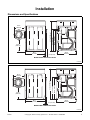
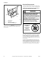
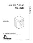
Installation
Frontload Washers
Para bajar una copia de estas instrucciones
en español, visite www.comlaundry.com.
FLW1522C
FLW1522C
Keep These Instructions for Future Reference.
(If this machine changes ownership, this manual must accompany machine.)
www.comlaundry.com
Part No. 801455R2
April 2012
Table of
Contents
Replacement Parts ..............................................................................
2
Installation........................................................................................... 3
Dimensions and Specifications............................................................. 3
Before You Start ................................................................................... 4
Tools ................................................................................................ 4
Electrical .......................................................................................... 4
Water................................................................................................ 4
Accessories Bag ............................................................................... 4
Installing the Washer ............................................................................ 5
Step 1: Position Washer Near Installation Area .............................. 5
Step 2: Connect Fill Hoses............................................................... 5
Step 3: Connect Drain Hose to Drain Receptacle ............................ 6
Step 4: Position and Level the Washer ............................................ 8
Step 5: Remove the Shock Sleeves and Shipping Brace ................. 9
Step 6: Wipe Out Inside of Washer Drum ....................................... 10
Step 7: (Supply Injection Models Only) Connect External
Supplies to Washer ......................................................................... 10
Control Function Test ...................................................................... 11
Step 8: Plug In the Washer............................................................... 11
Step 9: Check Installation ................................................................ 11
Moving Unit to a New Location ...................................................... 11
Electrical Requirements........................................................................ 12
Grounding Instructions .................................................................... 13
Water Supply Requirements ................................................................. 14
Water Temperature .......................................................................... 14
Water Pressure ................................................................................. 14
Risers................................................................................................ 14
Information for Handy Reference......................................................... 15
Installer Checklist ................................................................. Back Cover
© Copyright 2012, Alliance Laundry Systems LLC
All rights reserved. No part of the contents of this book may be reproduced or transmitted in any form or by any
means without the expressed written consent of the publisher.
801455
© Copyright, Alliance Laundry Systems LLC – DO NOT COPY or TRANSMIT
1
Replacement Parts
If replacement parts are required, contact the source
from which you purchased your washer, or contact:
Alliance Laundry Systems
Shepard Street
P.O. Box 990
Ripon, WI 54971-0990
U.S.A.
Phone: (920) 748-3950
for the name and address of the nearest authorized
parts distributor.
2
© Copyright, Alliance Laundry Systems LLC – DO NOT COPY or TRANSMIT
801455
Installation
Dimensions and Specifications
29.6 in. (75.1 cm)
41.2 in. (104.6 cm)
14.3 in.
(36.3 cm)
31.1 in. (79 cm)
17.5 in.
(44.8 cm)
28 in.
(71.1 cm)
2 in. (5.1 cm)
26.9 in.
(68.3 cm)
FLW2092N
MODELS WITH OLD STYLE DOOR
FLW2092N
28 in.
(71.1 cm)
29.6 in. (75.1 cm)
14.3 in.
(36.3 cm)
31.1 in. (79 cm)
41.2 in. (104.6 cm)
18.7 in.
(47.5 cm)
2 in. (5.1 cm)
26.9 in.
(68.3 cm)
FLW2044N
MODELS WITH NEW STYLE DOOR
FLW2044N
801455
© Copyright, Alliance Laundry Systems LLC – DO NOT COPY or TRANSMIT
3
Installation
Before You Start
Water
Tools
Washer needs two standard 3/4 in. (19.1 mm) water
supply faucets with a pressure between 20 and
120 pounds per square inch (138 to 827 kPa). For
more detailed information refer to section on Water
Supply Requirements.
For most installations, the basic tools you will need
are:
2
1
3
Accessories Bag
4
An accessories bag has been shipped inside your
washer. It includes:
• Two fill hoses with washers and filter screens.
Refer to step 2 of Installation.
• Four rubber feet. Refer to step 4 of Installation.
• Beaded tie-down strap. Refer to step 3 of
Installation.
5
• Installation instructions.
D820I
1
2
3
4
5
Wrench
Screwdriver
Pliers
Socket Wrench
Level
Figure 1
• Use and Care Guide.
• Operating insert.
• Warranty bond.
• Helpful Hints insert.
• Bag for storing shipping materials.
Electrical
Refer to serial plate for specific electrical
requirements. For more detailed information refer to
section on Electrical Requirements.
4
© Copyright, Alliance Laundry Systems LLC – DO NOT COPY or TRANSMIT
801455
Installation
Installing the Washer
Step 2: Connect Fill Hoses
NOTE: If the washer is delivered on a cold day
(below freezing), or is stored in an unheated room
or area during the cold months, do not attempt to
operate it until the washer has had a chance to
warm up.
NOTE: Refer to section on Water Supply
Requirements before connecting fill hoses.
Step 1: Position Washer Near Installation
Area
IMPORTANT: Install dryer before washer. This
allows room for attaching exhaust duct.
Move washer as close to the desired area of
installation as possible.
NOTE: For best performance and to minimize
vibration or movement, install washer on a solid,
sturdy and level floor. Some floors may need to be
reinforced, especially on a second floor or over a
basement. Do not install the washer on carpeting,
soft tile, a platform or other weakly supported
structures.
Turn on the water supply faucets and flush the lines for
approximately two minutes to remove any foreign
materials that could clog the screens in the water
mixing valve.
NOTE: When installing in newly constructed or
renovated building, it is very important to flush the
lines since build-up may have occurred during
construction.
Remove the two plain rubber washers and two filter
screens from accessories bag, and install them
according to Figure 3 and Figure 4.
NOTE: Check filter screens for debris or damage
annually. Clean or replace them if necessary.
IMPORTANT: Thread hose couplings onto valve
connections finger-tight, then approximately
1/4 turn with pliers. DO NOT cross thread or
overtighten couplings.
Turn water on and check for leaks. If leaks are found,
retighten the hose couplings. Continue tightening and
rechecking until no leaks are found.
1
3
2
W520I
W520I
1
FLW702N
FLW702N
2
3
Filter Screen (Screen must be facing
outward)
Fill Hose
Rubber Washer (Plain)
Figure 2
Figure 3
801455
© Copyright, Alliance Laundry Systems LLC – DO NOT COPY or TRANSMIT
5
Installation
IMPORTANT: Hoses and other natural rubber
parts deteriorate after extended use. Hoses may
develop cracks, blisters or material wear from the
temperature and constant high pressure they are
subjected to.
All hoses should be checked on a yearly basis for
any visible signs of deterioration. Any hose showing
the signs of deterioration listed above should be
replaced immediately. All hoses should be replaced
every five years.
1
2
3
Remove the drain hose from its shipping position on
the rear of the washer by unhooking the hose from the
retainer clamp and by removing shipping tape.
Find the instructions, on the following pages, that are
appropriate for your type of drain receptacle
(standpipe, sink, wall, or laundry tub). Follow these
instructions to properly install the drain hose.
IMPORTANT: Drain receptacle must be capable of
handling a minimum of 1-1/4 inch (3.2 cm) outside
diameter drain hose.
WATER
MIXING
VALVE
4
FLW1973N
FLW1973N
1
2
3
4
Step 3: Connect Drain Hose to Drain
Receptacle
1
Water Supply Faucets
Cold Water Connection
Hot Water Connection
Fill Hoses
Figure 4
FLW1958N
1
Retainer Clamp
Figure 5
Standpipe Installation
Place the drain hose into the standpipe.
Remove the beaded tie-down strap from accessories
bag and place around standpipe and drain hose and
tighten strap to hold hose to standpipe. This will
prevent the drain hose from dislodging from drain
receptacle during use.
6
© Copyright, Alliance Laundry Systems LLC – DO NOT COPY or TRANSMIT
801455
Installation
In-the-Wall Installation
For installations of this type, the drain hose MUST be
secured to one of the fill hoses using the beaded tiedown strap from accessories bag.
NOTE: End of drain hose must not be below 24 in.
(61 cm).
1
1
2
3
FLW1959N
FLW1959N
1
2
24 in. to 36 in. (91.44 cm recommended
height)
Standpipe 2 in. (5.08 cm) or 1-1/2 in. (4 cm)
Beaded Tie-Down Strap
2
3
Figure 6
3
Sink Installation
For this type of installation, use the beaded tie-down
strap (supplied in accessories bag) or use a large wire
tie (available from your local hardware store), and
secure the drain hose to the cabinet top hinge (refer to
Figure 7). This will prevent the drain hose from
dislodging during use.
H023I
1
2
3
Drain Hose
Tie-Down Strap (Tape if necessary)
Fill Hoses
Figure 8
1
2
FLW1960N
FLW1960N
1
2
Drain Hose
Tie-Down Strap (Wire tie or tape if
necessary)
Figure 7
801455
© Copyright, Alliance Laundry Systems LLC – DO NOT COPY or TRANSMIT
7
Installation
Laundry Tub Installation
Step 4: Position and Level the Washer
For this type of installation, the drain hose MUST be
secured to the stationary tub to prevent hose from
dislodging during use. Use the beaded tie-down strap
(supplied in accessories bag) to secure hose.
1
WARNING
Washers elevated above floor level must be
anchored to that elevated surface, base or
platform. The material used to elevate the
washer should also be anchored to the floor
to ensure that the washer will not walk or
that the washer can not be physically
pulled, tipped or slid from its installed
position. Failure to do so may result in
conditions which can produce serious
injury, death and/or property damage.
W306
Place washer in position on a solid, sturdy and level
floor. Installing the washer on any type of carpeting,
soft tile, a platform or other weakly supported
structures is not recommended.
2
FLW1961N
FLW1961N
1
2
Drain Hose
Tie-Down Strap (Tape if necessary)
Figure 9
Loosen 7/8 in. locknut and adjust the front and rear
leveling legs until the washer is level from side to side
and front to back (using a level). Washer should not
rock.
NOTE: Level must rest on raised portion of top
panel. Refer to Figure 10.
Tighten the locknuts securely against the washer
base using the 7/8 in. wrench. If the locknuts are not
tight, washer will move out of position during operation.
NOTE: DO NOT slide washer across floor if the
leveling legs have been extended, as legs and base
could become damaged.
NOTE: Use of the dispenser drawer or washer door
as a handle in the transportation of the washer may
cause damage to the dispenser or door.
8
© Copyright, Alliance Laundry Systems LLC – DO NOT COPY or TRANSMIT
801455
Installation
Remove rubber feet from accessories bag and place on
all four leveling legs.
Step 5: Remove the Shock Sleeves and
Shipping Brace
Verify that unit doesn’t rock.
Remove front access panel by removing the two screws.
3
2
Remove label from front side of front access panel and
place on backside of front access panel.
1
NOTE: The shipping brace, bolts, lockwashers and
shock sleeves should be saved and MUST be
reinstalled whenever the unit is moved more than
four feet. Do not lift or transport unit from front or
without shipping materials installed.
4
5
FLW2047N
FLW1944N
FLW2047N
1
2
3
4
5
Remove bolts and lockwashers from shipping brace
with 9/16 in. wrench and remove brace. Remove shock
sleeves by pulling on the yellow rope.
Leveling Leg
Washer Base
Level
Locknut
Rubber Foot
Store the shipping materials in the bag provided in the
accessories bag. Save materials for use whenever the
unit is moved.
NOTE: The shipping materials MUST be reinstalled
whenever the unit is moved. Refer to Moving Unit
to a New Location section for proper instructions on
reinstalling the shipping materials.
Reinstall front access panel.
Figure 10
IMPORTANT: DO NOT tip washer more than
6 inches (152.4 mm) in any direction after shipping
brace has been removed. Shock absorbers may
separate and damage to washer may result. For
leveling purposes, the washer may be tilted a
maximum of 6 inches (152.4 mm) in any direction.
1
2
4
H336I
3
H336I
1
2
3
4
Shock Sleeves
Motor Mount
Bolts and Lockwashers
Hooked End of Shipping Brace
Figure 11
801455
© Copyright, Alliance Laundry Systems LLC – DO NOT COPY or TRANSMIT
9
Installation
Step 6: Wipe Out Inside of Washer Drum
Before using the washer for the first time, use an
all-purpose cleaner, or a detergent and water solution, and a
damp cloth to remove shipping dust from inside the drum.
Supply Injection System
Number of liquid supply connections
(1–Detergent and 2–Softener)
2
Liquid supply connection size,
in. (mm)
3/8 (9.52)
or
1/4 (6.35)
WARNING
FLW2049N
FLW2049N
Wear eye and hand protection when
handling chemicals; always avoid direct
contact with raw chemicals. Read the
manufacturer’s directions for accidental
contact before handling chemicals. Ensure
an eye-rinse facility and an emergency
shower are within easy reach. Check at
regular intervals for chemical leaks.
SW016
Figure 12
Step 7: (Supply Injection Models Only)
Connect External Supplies to Washer
3
IMPORTANT: Undiluted chemical dripping can
damage the washer.
2
1
1. Remove two nozzles from accessories bag. Use
either the 3/8 inch or 1/4 inch nozzles, depending
on the diameter of the dispenser tubing used.
2. Attach nozzles to rear of machine. Connection
point located on cabinet, above water mixing
valve. Refer to Figure 13.
3. Connect supply hoses to nozzles and secure with
hose clamps (obtain locally). Refer to Figure 13.
NOTE: Hoses can be connected to either nozzle.
4. Refer to supply injection system instructions and
label inside washer junction box cover
(Figure 14) for electrical connection.
Do not attempt to make supply injection
electrical connections to points other than those
provided specifically for that purpose by the
factory.
5. Refer to supply injection system instructions for
details on operation.
10
FLW2027N
1
2
3
Injection Point
Nozzle
Supply Dispenser Pump Outlet
Figure 13
© Copyright, Alliance Laundry Systems LLC – DO NOT COPY or TRANSMIT
801455
Installation
A junction box on the rear panel houses a terminal
strip which furnishes supply output signals for the
supply injection pumps.These are dry contacts.
Voltage needs to be supplied. Refer to Figure 14 for
the injection interface label.
Step 8: Plug In the Washer
Refer to section on Electrical Requirements and connect
the washer to an electrical power source.
CHEMICAL INJECTION
ELECTRICAL INTERFACE
YELLOW
SOFTENER
DISPENSER
CONNECTION
YELLOW/BLACK
SOFTENER
RELAY
D254I
Plug cord into separately fused 15 Amp circuit.
RED
DETERGENT
DISPENSER
CONNECTION
RED/BLACK
DETERGENT
RELAY
D254I
Figure 15
Step 9: Check Installation
NO CONNECTION
Refer to Installer Checklist on the back cover and
make sure that unit is installed correctly.
TERMINAL
BLOCK
NOTE: Normally Open Contacts.
Contacts Close to Start Chemical Injection.
Maximum Load Connection per Contact:
1A @ 120VAC/240VAC
801653R1
FLW2028N
Figure 14
These terminals may be used to provide signals to the
supply injection system but must not be used to
provide power to the actual pump.
Any injection system pump which requires
110 VAC must be powered by a separate external
power source.
Control Function Test
The washer should be cleaned after the installation is
complete. A function test should then be executed on
the unloaded machine:
Moving Unit to a New Location
To prevent damage while moving the unit, the
shipping materials MUST BE reinstalled.
Reinstallation of Shipping Materials
Disconnect washer from electrical supply.
Remove front access panel by removing two screws.
Place the shock sleeves on all four shock absorbers.
Refer to Figure 16.
Insert hooked end of shipping brace into the open slot
of the motor mount. Attach with bolts and lockwashers.
Refer to Figure 16.
Reinstall front access panel.
1. Check the power supply for such characteristics
as correct voltage, phase, and cycles to be certain
they are correct for the washer.
2. Open manual shut-off valves to the washer.
3. Apply power to the washer.
801455
© Copyright, Alliance Laundry Systems LLC – DO NOT COPY or TRANSMIT
11
Installation
Electrical Requirements
1
(120 Volt, 60 Hertz with 3-Prong Grounding Plug)
NOTE: The wiring diagram is located behind the
control panel, inside the control cabinet.
WARNING
2
4
H336I
3
H336I
1
2
3
4
Shock Sleeves
Motor Mount
Bolts and Lockwashers
Hooked End of Shipping Brace
Figure 16
Refer to step 5 for proper procedures whenever the
unit is moved.
To reduce the risk of fire, electric shock,
serious injury or death, all wiring and
grounding MUST conform with the latest
edition of the National Electrical Code, ANSI/
NFPA No. 70, and such local regulations as
might apply. It is the customer’s
responsibility to have the wiring and fuses
checked by a qualified electrician to make
sure the laundry room has adequate
electrical power to operate the washer.
W227
DO NOT OVERLOAD
CIRCUITS
DO NOT USE AN
ADAPTER
DO NOT USE AN
EXTENSION CORD
D009I
Figure 17
The washer is designed to be operated on a separate
branch, polarized, three-wire, effectively grounded,
120 Volt, 60 Hertz, AC (alternating current) circuit
protected by a 15 Ampere fuse, equivalent fusetron or
circuit breaker.
The three-prong grounding plug on the power cord
should be plugged directly into a polarized three-slot
effectively grounded receptacle rated 110/120 Volts
AC (alternating current) 15 Amps. Refer to Figure 18
to determine correct polarity of the wall receptacle.
12
© Copyright, Alliance Laundry Systems LLC – DO NOT COPY or TRANSMIT
801455
Installation
3
1
WARNING
2
To reduce the risk of an electric shock or
fire, DO NOT use an extension cord or an
adapter to connect the washer to the
electric power source.
120 ± 12
V.A.C.
0
V.A.C.
W082
Grounding Instructions
5
The washer must be grounded. In the event of
malfunction or breakdown, grounding will reduce the
risk of electric shock by providing a path of least
resistance for electric current. The washer is equipped
with a cord having an equipment-grounding conductor
and a 3-prong grounding plug. The plug must be
plugged into an appropriate outlet that is properly
installed and grounded in accordance with all local
codes and ordinances.
120 + 12
V.A.C.
4
STANDARD 120 VOLT, 60 HERTZ, 3-WIRE
EFFECTIVELY GROUNDED CIRCUIT
WARNING
Improper connection of the equipmentgrounding conductor can result in a risk of
electric shock. Check with a qualified
electrician or service person if you are in
doubt as to whether the washer is properly
grounded.
W216
DO NOT modify the plug provided with the washer –
if it will not fit the outlet, have a proper outlet installed
by a qualified electrician.
NOTE: Have a qualified electrician check the
polarity of the wall receptacle. If a voltage reading
is measured other than that illustrated, the
qualified electrician should correct the problem.
WARNING
This unit is equipped with a three-prong
(grounding) plug for your protection
against shock hazard and should be
plugged directly into a properly grounded
three-prong receptacle. Do not cut or
remove the grounding prong from this
plug.
D799I
1
2
3
4
5
L1
Ground
Neutral Side
Round Grounding Prong
Neutral
Figure 18
DO NOT OPERATE OTHER APPLIANCES ON
THE SAME CIRCUIT. DO NOT OVERLOAD
CIRCUITS!
Do not operate both a washer and gas dryer on the
same circuit. Use separately fused 15 Amp circuits.
WARNING
To reduce the risk of electric shock or fire,
DO NOT use an extension cord or an
adapter to connect the washer to the
electrical power source.
W031
W213
801455
© Copyright, Alliance Laundry Systems LLC – DO NOT COPY or TRANSMIT
13
Installation
Water Supply Requirements
Under certain conditions, hydrogen gas may
be produced in a hot water system that has
not been used for two weeks or more.
HYDROGEN GAS IS EXPLOSIVE. If the hot
water system has not been used for such a
period and before using the washer, turn on
all hot water faucets and let the water flow
from each for several minutes. This will
release any accumulated hydrogen gas. The
gas is flammable. Do not smoke or use an
open flame during this time.
3
2
1
WARNING
WATER
MIXING
VALVE
4
FLW1973N
W029
NOTE: Water supply faucets must fit standard
3/4 in. (19.1 mm) female garden hose couplings.
DO NOT USE SLIP-ON OR CLAMP-ON
CONNECTIONS.
NOTE: Water supply faucets should be readily
accessible to permit turning them off when washer
is not being used.
Water Temperature
Cold:
FLW1973N
1
2
3
4
Water Supply Faucets
Cold Water Connection
Hot Water Connection
Fill Hoses
Figure 19
Water Pressure
Pressure must be a minimum of 20 to a maximum of
120 pounds per square inch (138 to 827 kPa) static
pressure measured at the faucet.
Hot:
NOTE: Water pressure under 20 pounds per
square inch (138 kPa) will cause an extended fill
time in the washer and may not properly flush out
the detergent dispenser.
Recommended hot water temperature is 120° to
140° Fahrenheit (49° to 60° Celsius).
Risers
Recommended cold water temperature is 60° to
80° Fahrenheit (16° to 27° Celsius).
Warm:
Mixture of hot and cold water (warm water
temperature is dependent upon the water temperature
and the pressure of both the hot and cold water supply
lines).
Risers (or air cushions) may have to be installed if the
pipes knock or pound when flow of water stops. The
risers are more efficient when installed as close as
possible to the water supply faucets (refer to Figure 20).
2
IMPORTANT: Turn off water supply faucets after
check-out and demonstration. Owner should turn
off water supply whenever there will be an
extended period of non-use.
NOTE: Longer fill hoses are available (as optional
equipment at extra cost) if the hoses (supplied with
the washer) are not long enough for the
installation. Order hoses as follows:
No. 20617 Fill Hose (8 ft.) (2.44 m)
No. 20618 Fill Hose (10 ft.) (3.05 m)
1
W005I
W005I
1
2
Water Supply Faucets
Risers (Air Cushions)
Figure 20
14
© Copyright, Alliance Laundry Systems LLC – DO NOT COPY or TRANSMIT
801455
Installation
Information for Handy Reference
Alliance Laundry Systems
Shepard Street
P.O. Box 990
Ripon, WI 54971-0990
U.S.A.
Date Purchased
Model Number
Serial Number
Dealer’s Name
Dealer’s Address
Phone Number
Service Agency
Service Agency Address
Phone Number
NOTE: Record the above information and keep your sales slip. Model and serial numbers are located on
the nameplate.
801455
© Copyright, Alliance Laundry Systems LLC – DO NOT COPY or TRANSMIT
15
Installer Checklist
Fast Track for Installing the Washer
(Refer to the manual for more detailed information)
1
5
• Position Washer Near
Installation Area.
• Remove the
Shock Sleeves and
Shipping Brace.
H336I
H336I
CHECK
CHECK
FLW702N
FLW702N
2
6
• Connect Fill Hoses.
• Wipe Out Inside
of Washer Drum.
W520I
W520I
FLW2049N
FLW2049N
CHECK
3
CHECK
7
• Connect Drain Hose
to Drain Receptacle.
(Supply Injection Models Only)
• Connect External
Supplies to
Washer.
FLW1959N
FLW1959N
CHECK
CHECK
4
FLW2027N
FLW2027N
8
• Position and
Level the
Washer.
CHECK
• Plug In the Washer.
FLW2047N
FLW2047N
CHECK
© Copyright, Alliance Laundry Systems LLC – DO NOT COPY or TRANSMIT
D254I
D254I