1
Installation
DIGITAL
Instructions
THERMOSTAT
53DFS250-SL
CoolingOnly,Heat Cool,and Heat Pump
B.
o
C.
D.
MULTI-STAGE • SEVEN DAY PROGRAMMABLE
1
STEP #2 WIRE CONNECTIONS
1
SAMPLE
2
WIRING
DIAGRAMS
STEP #3 TEST OPERATION
2
ADVANCED
2
SETUP
ABOUT ADVANCED
AND OPERATION
X
Flat Blade
Screwdriver
©
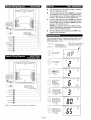
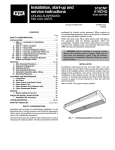
STEP #1 PREPARATION
Assemble tools:
Wire Cutter
and Stripper
Carefully unpack the thermostat. Save the screws,
bracket, and instructions.
Turn off the power to the system at the main fuse
panel. Most systems have a separate breaker for
disconnecting power to the indoor and outdoor
units.
_ / :l-JF_P-1
i'_'II tit:l [_o] _,I _,I <q / [o] _,[,.'t
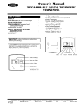
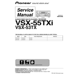
Refer to the chart below, or the wiring diagrams that
follow for thermostat functions and corresponding thermostat connectors.
INSTALL ON THE
NEW THERMOSTAT
CONNECTOR MARKED
FUNCTION
FEATURES
Lo Fan
3
TROUBLESHOOTING
5
5
CALIBRATION
I IMPORTANT: Follow Installation Instructions carefully
CAUTION: DISCONNECT POWER TO THE SYSTEM BEFORE INSTALLING THE NEW THERMOSTAT,
SERIOUS PERSONAL INJURY MAY RESULT,
Gt
Compressor
Y
Heating
24 v Power
H2
R
Common
C
Rev. Valve
O*
Hi Fan
G2
Remote Sensor +5vdc
RS+5
Remote Sensor Signal
Remote Sensor Ground
RS GND
Dry Contact Switch 1
CK1
Dry Contact Switch 2
Defrost
CK2
RS
H1
*Only used with Heat Pump systems.
This device complies with Part 15 of the FCC rules. Operation is subject to the following 2 conditions: (1) This
device may not cause harmful interference, and (2) This
device must accept any interference received, including
interference that may cause undesired operation.
_I:l:_
A.
r_|
I"J-'l=1;/-'I-'Y-'I/ [o]_,I
Proper installation of the thermostat will be accomplished by following these step by step instructions.
If you are unsure about any of these steps, call a
qualified technician for assistance.
Manufacturer
reserves the right to discontinue, or change at any time, specifications
Catalog No. 02-DFC535SI
Printed in U.S.A.
or designs
Form 53-5SI
without notice and without incurring obligations.
Pg 1
11-05
Replaces:
53-2SI
F..,lZ_TI_ kv_vtf'il_jII,._j_J_l i_I4
I: I__al/ I'.JI]F4"j
A.
B.
0
the thelmostat
to the
o
o
RS+5
CKt
RS
OK2
C.
D.
I-0
R_od
t_at
COMMON
o
cabN from lho
to th_ equipment.
_
POWER
cc /_t
LO FAN
_
COMPRESSOR
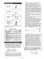
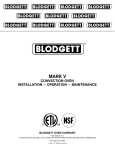
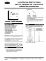
Turn the power on to the HVAC (heating, ventilation,
and air conditioning) system.
Press the Mode button until the HEAT icon appears
on the display. Press the Up or Down buttons until
the set temperature is 10 degrees above room temperature. The unit will turn on and supply heat.
Press the Mode button until the COOL icon appears
on the display. Press the Up or Down buttons until
the set temperature is 10 degrees below room temperature. The unit will turn on.
NOTE: Most equipment has a time delay between
cycles. This feature is defeatable on the thermostat.
See the Advanced Setup section.
Press the Mode button repeatedly until OFF is displayed on the thermostat.
_
>- _
............................................................................................................................................................................
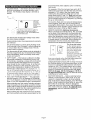
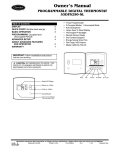
Follow the steps below to complete Advanced Setup, which
begins with Step 3. Refer to the Owner's Manual to complete Setup Steps 1 and 2.
...............................................................................................................................................................................
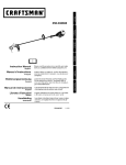
MODE
Press the Mode button,
While holdtn# the Mode
REVERSINGvALVEO I_t
AUX
HEAT
HIGH
FAN
DEFROST
PROGRAM
_: I_)
_
enter
the Advanced
button,
Setup
screens
I(÷}
_: I_
'_ ....................................................................................................................
J
(_
On
Select
residential
Q Pump,
press
the Program
On
or Off.
Heat
OFF
button to
Off
(_
Adjustthe
deadband
(_
frorn t (1to to6 6degrees.
F)
(_
Adjust the minimum
_between
cooling
and heating
_
setboints,
(0 to 6 P)
_)
hour
Select lirng.
the cycles per
d=cycles
per hour
J
3 conductor
18 gage
unsMelded
cable from
the thermostat
to the
RS43ND
_)
I-
Or_
dl=d + defeat 5 rain.
limit defeated.
Combresso_
lockout.
8Condoctor
1_,
1_g_
th
(d, dt,2-6)
unshieldedca
e rorn
e
thermostat
to the equipment.
Select
COMMON
24 v POWER
LOFAN
COMPRESSOR
located
NOTE:
atEach
the
top
step right number
corner
the display
for easy
reference.
the security
level:
0
O=no
Cc
t2=1+
=set program
point range
on all
limited
times
3=2 _ prohibits
set point
changes
_
security
in effect
>-
_)
AUX
NEAT
_:
NIGN
PAN
_
Adjust the maximum
allowable
heat set point
(Step
only appears
if
when 8
security
is in effect.
Step 7 is not O)
(35 - 99 F)
NOTE: For cooling only the H2 connection
is not required.
Adjust the cool
minimum
allowable
set point
when security
is in effect.
Step
(Step 7gisonly
not O)
appears
(35 - 99 F)
Page 2
if
_¢
is
of
i
This minimum difference is enforced during Auto
changeover and Program On operation.
• ENERGY SAVING SMART FAN -- If Fan On is
selected, the fan will run continuously at all times,
except in Off, and will only run if there is a heating
or cooling demand in Unoccupied periods.
• OVERRIDE -- Press the Override button during a
programmed, Unoccupied period to force the thermostat into the Occupied 1 period, temporarily, up
to 4 hours. If the Override button is pressed during
an Occupied period, the thermostat will be forced
into the Unoccupied period and the occupied number (1,2 or 3), it was forced out of will be turned off,
only for that day.
During Override periods the set point temperature
may be adjusted, but it will not be remembered after
Override ends.
[r4'am]
c
F
Select thermostat
operation
j)
in degrees
Fahrenheit
or Celsius.
F
_J
_On
Select the display back-
(_
after 8 seconds.
light always On, or Off
off
ON
Adjust the preoccupancy
fan purge timer.
0:00 = off
0 - 3 hours.
Z
_3
• HEAT-- First Stage = Heat Pump. Second Stage =
Heat Pump and Electric Heat.
• FAN PURGE TIMER -- When this feature is activated, the fan will turn on during the Unoccupied
period at a preset amount of time prior to the Occupied 1 period. This preoccupancy fan purge timer
may be set as instructed on this page, Step 12,
from 0 to 3 hours. 0 = this feature turned off.
{ttp
Se/up
'Soft Start'.
This is used
n
in multiple installs to
on times. 0 = off.
stagger equipment turn
Each
(30seconds)
Select Number
the unit =ID
for
second delay,
(_
• KEYPAD LOCK -- To prevent unauthorized use of
the thermostat, the front panel buttons may be disabled. To disable, or 'lock' the keypad, press and
hold in the Mode button. While holding the Mode
button in, press the Up and Down buttons in together. The Locked icon will appear on the display.
_ _y
(0 to 99)
Press the Mode button. While holding the Mode, press the Program button to
leave the Setup screens, If no buttons are pressed, the display will leave the
setup screens after 30 seconds.
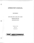
Advanced Setup Table
STEP
NO.
1
2
3
4
5
DESCRIPTION
Time of day clock set
Day of the week
Heat Pump
Deadband or Temperature swing
Forced minimum difference heat/
,_ool
RANGE
FACTORY
DEFAULT
24 hour
Su - Sa
Off / On
1 -6 F
12:00 Am
Mo
Off
2 F
0 -6 F
2 F
6
7
8
9
10
Cycles per hour
Security Levels
Maximum allowable Heat set point
Minimum allowable Cool set point
Fahrenheit or Celsius
d, dl, 2 - 6
0 -3
35 - 99 F
35 - 99 F
F/C
6
0
80 F
65 F
F
11
Thermoglow
On
12
Fan Purge timer
Off / On
0:00 - 3;00
min,
0:00 min,
13
Soft Start
0 - 99
0
TM
backlight
Press all 3 for _
Keypad Lockout _
3rdStage
High
2ndStage
rnon
2nd Stage
Mad
Coo_
Se/PoJnt
[ Looked
ON
_S
SS
IMPORTANT: Forcontrol of multiple thermostats by
[
one source, refer to Potential Phasing Problems (document part no. 88-173) prorto nsta ng.
I
Coo_ing
lstStage
Heat
turnon
SetPoint
1st Stage
"_
_i_[_in_°n
To unlock the buttons, again press and hold the
Mode button. While holding the Mode button in,
press the Up and Down buttons in together. The
Locked icon will disappear from the display.
DRY CONTACT SWITCH -- The terminals are 'normally open.' Closing or completing the circuit will
cause the thermostat to enter the Occupied 1
period. This feature allows an external device such
as a central time clock, occupancy sensor, or a
telephone-activated device to force one or more
thermostats into the Occupied 1 period. For the dry
contact switch to work, the thermostat must be in
Program On. Set Occupied 1 to Off for all 7days,
so the contact closure will be in control. When the
thermostat is forced into the Occupied 1 period via
the Dry Contact closure, the icon Occupied 1 will
blink.
TWO-STAGE OPERATION -- The second stage of
heat (heat pump models only) is turned on when (1)
the first Stage has been on for a minimum of two
minutes, and (2) the temperature spread from the
set point is equal to or greater than: the setpoint
temperature plus the deadband, plus 2 degrees.
Heating
[
turnon
Low
Mad
High
_
Fan Speeds
LOW
MINIMUM HEAT/COOL SET POINT DIFFERENCE
-- The Heat and Cool set point temperature will not
be allowed to come any closer to each other than
the value set in Advanced Setup Step 5, on page 2.
Page 3
amount that they were adjusted, prior to entering
Auto mode.
HOLIDAY MODE -- This feature forces the thermostat into Unoccupied for a preset duration, up to
99 days, The Holiday setup display is entered as
follows:
For example: If the Cool set point was set to 80 F
while in the Cool mode and the Heat set point was
adjusted to 70 F while in the Heat mode, upon
entering the Auto mode the Heat and Cool set
points would be 80 F and 70 E Both set point temperatures would then move up and down together,
(in this example spread by 10 degrees), by pressing
the up or down buttons.
To move the Heat and Cool set point temperatures
closer together, enter the Cool or Heat mode by
pressing the Mode button, then adjust the set point
temperatures closer together. Heat is limited to how
close it can come to Cool by Step 5, page 2.
REMOTE SENSORS (Optional Accessory) -When connected to terminals RS+5, RS, and GND
on the back of the thermostat, the thermostat will
read the temperature from the remote sensor and
ignore the temperature sensor inside the thermostat. The thermostat automatically recognizes when
a remote sensor is connected. When reading the
temperature from the remote, the degree icon
above the room temperature blinks once a second.
The Override button
on the remote sensor
works slightly different
than the Override button on the front panel.
Optional
Each press of the
Remote Sensor
'External' Override butOptional Sensor
ton adds 2 hours to the
override timer, if the
timer was already active, the first button press will
round the runtime to either 2:00 or 4:00.
HOLIDAY
HOL
acti
the display
i_
_Anlbl
S
@
counts down
remaining
days
Unoccupied
blinking.
also
appears.
/
/,
Press the Up or Down buttons to select the
....................
_
number of days the thermostat will be in
/
Holiday mode. 0 = Off.
press the Mode button.
To exit Holiday
setup,
The thermostat will enter the Holiday mode when
the clock crosses midnight.
During Holiday mode Unoccupied period set points
are enforced.
The Override button is active during Holiday mode.
It will override to the Occupied 1 period settings up
to 4 hours then return to Holiday mode. The dry
contact switch is ignored.
The thermostat will exit Holiday mode at midnight of
the final programmed day. To terminate the Holiday
mode immediately, enter the Holiday mode setup
screen and select O.
SOFT START -- This feature is utilized in multiple
thermostat installations controlled by the dry contact terminals. Assigning a unique soft start number
to each thermostat will stagger the turn on times,
even though the dry contact closes, for all the thermostats connected, at the same time. Each soft
start number represents a multiple of 30 seconds
from the dry contact closure. For example, no. 1 =
turn on 30 seconds after dry contact closure, no. 2
= turn on 60 seconds after closure, no. 3 = turn on
90 seconds after closure, and so on. See page 3,
Step 13, to configure the thermostat for Soft Start.
DUAL SET POINT BEHAVIOR -- The adjustable
set point range is: 35 to 99 degrees in Fahrenheit
and 7 to 35 degrees in Celsius. When in the modes
Heat or Cool, this adjustable range is unhampered.
When adjusting any Auto mode, including programming Occupied and Unoccupied set points, the thermostat will not allow the Heat set point to get closer
to the Cool set point than the value programmed as
the minimum difference in Step 5, page 2.
When entering the Auto mode from Cool, the Heat
and Cool set points will remain spread apart by the
Subsequent button presses will not wrap around as
the Override button on the thermostat does, so the
second or subsequent button presses will set the
runtime to 4:00. The Locked feature has no effect
on the external Override button. The wired remote
sensor is connected to the thermostat with up to
450 ft of 22 gage, 300 ft of 20 gage or 150 ft of
18 gage thermostat wire. See the Remote Sensor
instructions for further details.
FACTORY DEFAULTS -- Before restoring factory
defaults, set thermostat to OFF mode. If, for any
reason it is desirable to return all stored settings
back to the factory default settings, press the Mode
button. While holding the Mode button in, press the
Fan button for 5 seconds. All icons will appear.
Press and hold in the Fan button until Fd appears.
This resets all factory settings. To calibrate room
temperature, see the Calibration section on
page 5.
Page 4
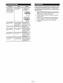
ii ;[oil] :] II :[,.']:[oIo]l/ I_[_
SYMPTOM
When not using a
common wire the air
conditioning
equipment tries repeatedly
to turn on, but cannot.
At times the display
dims or disappears.
[@±Ie I:1;T±'ai [e] ZI
CAUSE
The air conditioning
does not attempt to
turn on.
The compressor timer
lockout may prevent
the air conditioner
from turning on, for a
)eriod of time.
The display
Lack of proper
is blank.
Every thermostat is calibrated before it leaves the factory.
Under normal circumstances there will never be a need
to recalibrate the thermostat again. To accommodate
special needs, the thermostat may be recalibrated following these steps:
1. While holding the Mode button in, press the fan
button in for 5 seconds. After all the icons in the
display appear, release the buttons.
2. Press the Up and Down arrow buttons simultaneously, twice.
3. Press the up or down buttons until the flashing
number equals the current room temperature.
4. Press the Mode button to return to normal
operation.
REMEDY
There is not enough
_ower available to
3ower share."
power.
Connect a 270 ohm,
10 watt power resistor at the unit as
shown below.
For Problem
A/C
For Problem
Heat
See the Advanced
Setup section to
defeat the cycles per
hour and compressor
time guard.
Check for 24 vac
between R and C.
The air conditioning
does not attempt to
turn on.
The cooling set point
is set too high.
Press the down arrow
until the cooling set
_oint is 10 degrees
lower than the room
temperature.
The heating does not
attempt to turn on.
The heating set point
is set too low.
Press the up arrow
until the heating set
_oint is 10 degrees
higher than the room
temperatu re.
The strip heater turns
off well before reaching set point.
Heat pump is incorrectly selected "on" in
the Advanced
Setup.
Select heat pump
"off" during Advanced
Setup programming.
See the Advanced
Setup section
Page 5
Copyright 2005 Carrier Corporation
Manufacturer reserves the right to discontinue,
Catalog No. 02-DFC535SI
or change at any time, specifications
Printed in U.S.A.
or designs without notice and without incurring obligations.
Form 53-5SI
Pg 8
11-05
Replaces:
53-2SI