1
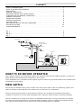
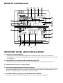
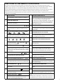
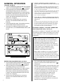
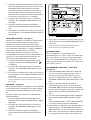
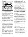
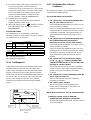
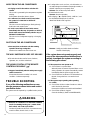
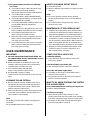
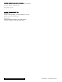
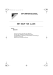
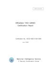
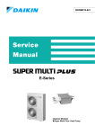
OPERATION MANUAL
SPLIT SYSTEM
Ducted Air Conditioner
Using Remote Controller BRC1C61
C
hr
Dear Owner,
Thank you for installing a DAIKIN Fully Ducted Air Conditioning System. We believe that
you have purchased the best air conditioning system available.
Before operating the air conditioner please read this operating manual carefully. It will
advise you on how to operate the unit correctly, understand the air conditioner’s advanced
features and help you in the unlikely event that a problem should occur.
Please keep this manual in a safe place for future reference.
DAIKIN AUSTRALIA PTY. LIMITED
SAFETY CONSIDERATIONS
!
We recommend that you read this instruction manual carefully
before use to gain full advantage of the functions of the air
conditioner and to avoid malfunction due to mishandling. This
air conditioner comes under the term “appliances not accessible to
the general public”.
The precautions described below are WARNING and CAUTION. These are very important precautions
concerning safety. Be sure to observe all of them without fail.
WARNING ...... These are the matters with possibilities leading to serious consequences such as death or serious injury due
to erroneous handling.
CAUTION ....... These are the matters with possibilities leading to injury or material damage due to erroneous handling
including probabilities leading to serious consequences in some cases.
!
After reading, keep this manual at a place where any user can read at any time. Furthermore, make
certain that this operation manual is handed to a new user if required.
WARNING
! Avoid prolonged exposure of your body to direct streams
of cold air.
Your physical condition may deteriorate.
! If the air conditioner is in abnormal conditions (smell of
something burning, etc.), switch the air conditioner off at
the main switch, and contact the dealer where you
purchased the air conditioner.
Continued operation under such circumstances may result
in a failure, electric shock or fire.
! Only use a qualified installer for installation of the air
conditioner.
Incorrect installation performed may result in a water
leakage, electric shock or fire.
! Ask your dealer for improvement, repair, and maintenance.
Incorrect improvement, repair, and maintenance may result
in a water leakage, electric shock or fire.
! Never remove any fixed covers on the indoor or outdoor
unit.
Removal of the covers may expose fast moving fan blades
or electrical components operating at a hazardous voltage.
Contact with the blades or high voltage componenets may
result in injury or electric shock.
! For refrigerant leakage, consult your dealer.
If the air conditioner is to be installed in a small room,
it is necessary to take proper measures so that the amount
of any leaked refrigerant does not exceed the limiting
concentration. If the refrigerant leaks exceeding the level of
limiting concentration, an oxygen deficiency accident may
happen.
! For installation of separately sold component parts,
ask a specialist only.
Be sure to use separately sold component parts designated
by Daikin. Incomplete installation performed by yourself
may result in a water leakage, electric shock or fire.
! Ask your dealer to move and reinstall the air conditioner.
Incomplete installation may result in a water leakage,
electric shock or fire.
! Never insert any objects into the openings in the indoor or
outdoor unit.
This may damage the product or result in injury to the
person inserting the object.
CAUTION
! Do not use the air conditioner for other purposes.
!
!
!
!
!
!
2
Do not use the air conditioner for special applications such
as the storage of foods, animals and plants, precision
machines, and art objects. Deterioration of quality may
result.
When the air conditioner is used in combination with
burners or heaters, ensure sufficient ventilation.
Insufficient ventilation may result in an oxygen deficiency
accident.
Reguarly check the quality of the foundation blocks.
If they are left in a damaged condition, the unit may fall and
result in injury.
Do not place or use a flammable spray can near the air
conditioner.
Doing so may result in a fire.
To clean the air conditioner, stop operation and switch the
power off at the main switch.
Otherwise, an electric shock and injury may result.
Do not expose the indoor unit or remote controller to rain
or moisture.
Water or other fluids on the electrical components may
result in fire or electric shock.
Always replace any blown fuse with a fuse of the same
specification.
The use of the wrong type fuse may allow the electrical
wiring to overheat and catch on fire. If the correct type of
fuse continues to blow contact your installer or electrician.
! Do not place a burner or heater at a place directly
exposed to the wind from the air conditioner.
Incomplete combustion of the burner or heater may result.
! This electrical appliance is not intended for use by young
children or infirm persons without supervision.
Young children should be supervised to ensure that they do
not play with the outdoor unit.
! Do not expose animals and plants directly to the air stream
from the outdoor unit.
Adverse influence to animals and plants may result.
! Do not wash the air conditioner with water.
An electric shock may result.
! Do not install the air conditioner at any place where
flammable gas may be present.
If the gas leaks out and stays around the air conditioner, a
fire may break out.
! Execute complete drain piping for perfect drainage.
Incomplete piping may result in a water leakage.
! Never operate the air conditioner without the return air
filter(s) in place.
Operating the unit without the filter(s) will allow dust to
enter the indoor unit and build up on the heat exchanger
coil and fan motor. This will cause a malfunction of the unit
which will not be covered by Warranty.
CONTENTS
SAFETY CONSIDERATION . . . . . . . . . . . . . . . . . . . . . . . . . . . . . . . . . . . . . . . . . . . . . . . . . .
WHAT TO DO BEFORE OPERATION . . . . . . . . . . . . . . . . . . . . . . . . . . . . . . . . . . . . . . . . . .
MAIN SWITCH . . . . . . . . . . . . . . . . . . . . . . . . . . . . . . . . . . . . . . . . . . . . . . . . . . . . . . . . . . .
REMOTE CONTROLLER . . . . . . . . . . . . . . . . . . . . . . . . . . . . . . . . . . . . . . . . . . . . . . . . . . .
IMPORTANT NOTES ABOUT INSTALLATION . . . . . . . . . . . . . . . . . . . . . . . . . . . . . . . . . . . .
FUNCTIONS OF THE REMOTE CONTROLLER . . . . . . . . . . . . . . . . . . . . . . . . . . . . . . . . . .
GENERAL OPERATION . . . . . . . . . . . . . . . . . . . . . . . . . . . . . . . . . . . . . . . . . . . . . . . . . . . .
ADVANCED FEATURES . . . . . . . . . . . . . . . . . . . . . . . . . . . . . . . . . . . . . . . . . . . . . . . . . . . .
OPTIMUM OPERATION . . . . . . . . . . . . . . . . . . . . . . . . . . . . . . . . . . . . . . . . . . . . . . . . . . . .
SELF DIAGNOSIS . . . . . . . . . . . . . . . . . . . . . . . . . . . . . . . . . . . . . . . . . . . . . . . . . . . . . . . .
NOT MALFUNCTION OF THE AIR CONDITONER . . . . . . . . . . . . . . . . . . . . . . . . . . . . . . . .
TROUBLE SHOOTING . . . . . . . . . . . . . . . . . . . . . . . . . . . . . . . . . . . . . . . . . . . . . . . . . . . . .
USER MAINTENANCE . . . . . . . . . . . . . . . . . . . . . . . . . . . . . . . . . . . . . . . . . . . . . . . . . . . . .
Fig.
Fig.
Fig.
Fig.
1
2
3,
5
..
..
4
..
.
.
.
.
.
.
.
.
.
.
.
.
.
.
.
.
.
.
.
.
.
.
.
.
.
.
.
.
.
.
.
.
.
.
.
.
.
.
.
.
.
.
.
.
.
.
.
.
.
.
.
.
.
.
.
.
Discharged air
.
.
.
.
.
.
.
.
.
.
.
.
.
.
.
.
.
.
.
.
.
.
.
.
.
.
.
.
.
.
.
.
.
.
.
.
.
.
.
.
.
.
.
.
.
.
.
.
.
.
.
.
.
.
.
.
.
.
.
.
.
.
.
.
.
.
.
.
.
.
.
.
.
.
.
.
.
.
.
.
.
.
.
.
.
.
.
.
.
.
.
.
.
.
.
.
.
.
.
.
.
.
.
.
.
.
.
.
.
.
.
.
.
.
.
.
.
.
.
.
.
.
.
.
.
.
.
.
.
.
.
.
.
.
.
.
.
.
.
.
.
.
.
.
.
.
.
.
.
.
.
.
.
.
.
.
.
.
.
.
.
.
.
.
.
.
.
.
.
.
.
.
.
.
.
.
.
.
.
.
.
.
.
.
.
.
.
.
.
.
.
.
.
.
.
.
.
.
.
.
2
3
3
4
4
5
6
8
8
9
9
10
11
4
6
7
9
Indoor unit
Refrigerant piping,
connection electric wire
Drain pipe
Inlet air
Inlet air
Outdoor unit
RY71
RZP71
Inlet air
Remote
controller
RY100 ! 125 ! 160
RZP100 ! 125 ! 145
Discharged air
WHAT TO DO BEFORE OPERATION
This operation manual is for the following systems with standard control. Before initiating operation, contact your
Daikin dealer for the operation that corresponds to your system.
If your installation has a customized control system (eg zone control) ask your Daikin dealer for the operation that
corresponds to your system.
MAIN SWITCH
Ensure that your installer shows you the location of the main power switch of the air conditioning systems. This
switch is normally located adjacent to the outdoor unit or in the fuse box / switchboard.
The main switch must be turned on at least 6 hours before the air conditioner is operated to warm up the
compressor. Failure to do so may result in damage to the compressor which will not be covered by warranty.
If the air conditioner is not going to be used for an extended period of time or you are going away on holidays,
the main switch should be turned off to prevent accidental operation of the air conditioner. Remember that the
main switch must be turned back on at least 6 hours before operating the air conditioner.
3
REMOTE CONTROLLER
11
5
4
2
1
3
7
hr
C
6
8
hr
NOT
AVAILABLE
TEST
L H
9
10
12
13
20
19
TEST
15
18
14
16
17
Fig. 1
IMPORTANT NOTES ABOUT INSTALLATION
4
!
Ensure the outdoor unit is installed in:a. A place that can sufficiently withstand the weight of the air conditioner with less running noises and vibrations.
b. A place where the hot air stream discharged from the air outlet of the outdoor unit and the running noises do not bother
your neighbours.
!
Ensure that there are no obstacles near the air outlet of the outdoor unit.
Obstacles such as plants, boxes, fences, etc. may result in declined performance and increased running noises.
!
If abnormal noises occur in use, consult your dealer.
!
Ensure the drain piping from the indoor unit is free of blockage.
During cooling operation, water should drip from the outlet of the indoor unit’s drain piping. If there is no evidence of water
from the drain outlet after several hours of cooling it may be that the drain is blocked or the relative humidity is low. If you
think the drain is blocked stop the air conditioner and contact your installer.
!
Ensure that a separate power supply circuit is provided for this air conditioner.
All electrical work is to be carried out by qualified personnel according to local laws and regulations.
FUNCTIONS OF THE REMOTE CONTROLLER
All controls except for the ON / OFF BUTTON are located behind a swing door on the bottom half of the remote
controller. To access these controls simply open the door by gently pulling down on the finger grip located on the top
right hand edge of the door. To close the door simply swing it back up until it clicks into the closed position.
Once the desire temperature, fan speed and mode of operation have been set there is no need to access the controls
behind the door. Basic operation of the air conditioner is simply a matter of pressing the ON / OFF BUTTON.
Please note that the selected temperature, fan speed and mode of operation will always be displayed even when the air
conditioner is not operating.
ON/OFF BUTTON
NON FUNCTIONING DISPLAY
1
Press the button to start or stop the air conditioner.
12
OPERATION INDICATOR
2
This indicator illuminates (RED) when the air
conditioner is operating.
CENTRALISED CONTROL INDICATOR "
3
"
TIMER MODE START / STOP BUTTON
13
This symbol indicates that the air conditioner is
under control from an optional centralised control
panel.
HEAT RECLAIM VENTILATION / AIR CLEANING
"
""
""
""
"
14
This symbol indicates that the optional Heat Reclaim
Ventilation Unit is operating. (for commercial use).
Press this button after entering the desired off/on
time to initiate the timer function.
OPERATION DISPLAY
"
""
""
""
""
"
Fan
Dry
Auto
Cool
Heat
INSPECTION / TEST OPERATION BUTTON
This button is for use by installation or service
technicians only.
TEST "
PROGRAM TIME BUTTON
This symbol flashes to indicate that TEST /
INSPECTION BUTTON has been pressed or that the
microprocessor has determined that a fault condition
has occurred.
PROGRAM TIME INDICATOR "
7
15
This display shows the current OPERATION MODE.
For cooling only type, "
" (Auto) and "
"
(Heating) are not selectable.
INSPECTION / TEST INDICATOR "
6
hr
hr
17
These symbols and numbers indicate the
programmed stop (off) and start (on) time.
C
"
Push on the up arrow to increase the desired room
temperature. Push on the down arrow to decrease
the desired room temperature.
FILTER CLEAN RESET BUTTON
18
This display indicates the desired room temperature.
Press this button to reset the CLEAN FILTER
INDICATOR after you have inspected / cleaned the
indoor return air filter.
FAN SPEED DISPLAY "
FAN SPEED SELECTOR BUTTON
"
This display indicates the selected fan speed (ie.
high or low).
FILTER CLEAN INDICATOR "
19
"
This symbol indicates that the indoor return air filter
may require cleaning.
DEFROST INDICATOR "
11
Push on the up arrow to increase the desired
program stop / start time. Push on the down arrow to
decrease the desired program stop / start time.
TEMPERATURE SET BUTTON
8
10
16
"
SELECTED TEMPERATURE DISPLAY "
9
Press this button to select the setting for timer stop.
Press the button a second time to select the setting
for timer start.
PROGRAM TIMER ON / OFF BUTTON
4
5
If a particular function is not available, pressing the
button may display the words "NOT AVAILABLE" for
a few seconds. When running multiple units
simultaneously the "NOT AVAILABLE" message will
only appear if none of the indoor units is equipped
with the function. Even if one unit is equipped, the
display will not appear.
Press this button to toggle between high and low fan
speed.
OPERATION MODE SELECTOR BUTTON
20
Press this button to change the desired mode of
operation. (ie. fan, program dry, auto, cool, heat).
"
NOTE:
This symbol indicates that the air conditioner is in the ! For the sake of explanation, all indications are shown on
the display in Fig. 1 contrary to actual running situation.
process of removing the build up of ice on the
outdoor unit. (Heat Pump model only).
5
4. Select the desired fan speed (if required) by
pressing the FAN SPEED SELECTOR BUTTON (19).
GENERAL OPERATION
COOLING (see Fig. 2)
1. Press the MODE SELECTION BUTTON (20) (if required)
until the COOL MODE INDICATOR (
) is displayed.
2. Select the desired room temperature (if required) by
momentarily pressing on the up or down arrow
TEMPERATURE SET BUTTON's (17) until the desired
temperature is displayed. Each press of the button will
increase or decrease the desired temperature by 1
degree. The desired temperature may be set in the
range of 16 - 32 degrees.
3. Press the ON / OFF BUTTON (1) to commence
operation. The OPERATION INDICATOR (2) will
illuminate.
4. Select the desired fan speed (if required) by pressing
the FAN SPEED SELECTOR BUTTON (19).
5. To turn the air conditioner off simply press the ON /
OFF BUTTON (1). The OPERATION INDICATOR (2) will
turn off.
hr
C
NOT
AVAILABLE
L H
20
17
TEST
19
Fig. 2
HEATING (Heat Pump Models Only) (see Fig. 2)
1. Press the MODE SELECTION BUTTON (20) (if required)
until the HEAT MODE INDICATOR (
) is displayed.
2. Select the desired room temperature (if required) by
momentarily pressing on up or down arrow
TEMPERATURE SET BUTTON's (17) until the desired
temperature is displayed. Each press of the button
will increase or decrease the desired temperature by
1 degree. The desired temperature may be set in the
range of 16 - 32 degrees.
3. Press the ON / OFF BUTTON (1) to commence
operation. The OPERATION INDICATOR (2) will
illuminate.
6
5. To turn the air conditioner off simply press the ON /
OFF BUTTON (1). The OPERATION INDICATOR (2)
will turn off.
Note:
On some occasions the indoor fan will continue to run at extra
low (or low) speed for approximately one minute after the unit
has been switched off. This is not a malfunction, it is simply a
function of the unit which runs the indoor fan to remove any
excess heat in the indoor unit heat exchanger.
AUTOMATIC HEATING / COOLING CHANGEOVER
(Heat Pump Models Only) (see Fig. 2)
PMV Control (for Super Inverter Models only)
1
TEST
During the heating mode you may notice the indoor fan changing
speed. This is due to the fan switching from the selected fan
speed to extra low (or low) when the desired room temperature
is reached and the compressor cycles off.
This is to avoid cold draughts.
When the air conditioner is operated in this mode, it will
automatically switch between the heating and cooling
modes, depending on the room temperature and set
temperature.
2
hr
Notes:
As the air conditioner incorporates a hot start system, the indoor
fan will run at an extra low (or low) speed irrespective of the
selected fan speed for a few minutes when the unit is first turned
on. This is to avoid cold draughts.
When in the automatic cool / heat changeover
mode, the Predicted Mean Vote (PMV) control is
activated. By initially manually increasing or
decreasing the set temperature in this mode (for
increased comfort) over a period of time, the PMV
control “learns” and “remembers” these
temperature settings as well as prevailing
conditions - both inside and outside.
When similar conditions occur again, the system
automatically controls the temperature settings
according to the learnt preferences. This not only
can save in running costs (as it avoids over cooling
and over heating) but can also increase comfort
levels.
1. Press the MODE SELECTION BUTTON (20) (if
required) until the AUTO MODE INDICATOR (
is displayed.
)
When the AUTO MODE is selected either the COOL
or HEAT MODE INDICATOR will also be displayed
along with the most recent temperature setting.
(ie. if the last adjustment you made was to set the
cooling mode temperature to 23° then when you
select the AUTO MODE it will display AUTO
COOLING at a temperature of 23°). The air
conditioner will then measure the room
temperature and select the applicable mode
(ie. heating or cooling) based on the current and
desired room temperature.
2. Adjust the desired room temperature (if required)
by momentarily pressing on the up or down arrow
TEMPERATURE SET BUTTON's (17) until the
desired temperature is displayed. Each press of
the button will increase or decrease the desired
temperature by 1 degree. The desired temperature
may be set in the range of 16 - 32 degrees.
3. Press the ON / OFF BUTTON (1) to commence
operation. The OPERATION INDICATOR (2) will
illuminate.
4. Select the desired fan speed (if required) by
pressing the FAN SPEED SELECTOR BUTTON
(19).
5. To turn the air conditioner off simply press the ON /
OFF BUTTON (1). The OPERATION INDICATOR (2)
will turn off.
2
1
hr
C
hr
NOT
AVAILABLE
TEST
L H
9
8
20
TEST
Fig. 3
PROGRAM DRY MODE (see Fig. 3)
When the air conditioner is operated in this mode the
microprocessor will give priority to reducing the
humidity level rather than the room temperature.
(Please note that there may still be some reduction in
room temperature depending on ambient conditions).
This mode is normally used in very humid
environments where the conditions may still be
uncomfortable even though the room temperature is
fairly low. The air conditioner will not enter the dry
mode if the room temperature is below 16°C.
1. Press the MODE SELECTION BUTTON (20) (if
required) until the DRY MODE INDICATOR (
)
is displayed.
2. Press the ON / OFF BUTTON (1) to commence
operation. The OPERATION INDICATOR (2) will
illuminate.
3. To turn the air conditioner off simply press the ON /
OFF BUTTON (1). The OPERATION INDICATOR (2)
will turn off.
Please note that the SELECTED TEMPERATURE DISPLAY (8)
and FAN SPEED DISPLAY (9) will not appear during PROGRAM
DRY operation.
FAN MODE (see Fig. 2)
When the air conditioner is operated in the FAN MODE
only the indoor fan is energised. The outdoor unit will
not operate and therefore heating or cooling will not
be
provided. This mode is useful for circulating the air
within the building.
1. Press the MODE SELECTION BUTTON (20) (if
required) until the FAN MODE INDICATOR (
) is
displayed.
2. Press the ON / OFF BUTTON (1) to commence
operation. The OPERATION INDICATOR (2) will
illuminate.
3. Select the desired fan speed (if required) by
pressing the FAN SPEED SELECTOR BUTTON
(19).
4. To turn the air conditioner off simply press the ON /
OFF BUTTON (1). The OPERATION INDICATOR (2)
will turn off.
Please note that the SELECTED TEMPERATURE DISPLAY
(8) will not appear during FAN MODE operation.
PROGRAM TIMER
The air conditioner can be programmed to
automatically turn on or off in 1 hour increments up to
72 hours in advance. It may also be programmed to
turn on for a determined time then off again or vice
versa provided that the last operation (ie. switch on or
off) is within 72 hours.
PROGRAMMING THE START / STOP TIME
(see Fig. 4)
1. Press the TIMER MODE START/STOP BUTTON
(13) once to enter the program STOP mode, or
twice to enter the program START mode. The
symbol “O” indicates STOP, and “|” START. The
PROGRAM START/STOP TIME INDICATOR (7) will
flash.
2. Select the desired START/STOP TIME by
momentarily pressing on the up or down arrow
PROGRAM TIME BUTTON's (16) until the desired
elapsed time is displayed. Each press of the button
will increase or decrease the elapsed time by
1hour.
3. Once the desired START/STOP TIME is displayed
press the PROGRAM TIMER ON/OFF BUTTON
(14).
The PROGRAM START or STOP TIME INDICATOR
(7) will stop flashing and remain displayed.
4. Operate the air conditioner in the desired mode as
described above. The PROGRAM START/STOP
TIME INDICATOR (7) will count down towards zero.
When zero is reached the air conditioner will start
or stop operating depending on the program set.
7
HOT START SYSTEM (Heat Pump Models only)
To prevent a cold draft when the air conditioner turns
on in the heating mode the indoor unit incorporates a
computer controller hot start system.
hr
7
C
hr
NOT
AVAILABLE
TEST
L H
13
TEST
14
16
Fig. 4
It is possible to set both the start and stop time so that
the air conditioner either starts after a predetermined
time and then stops after a further predetermined time
or stops after a predetermined time and then starts
again after a further predetermined time.
This is achieved by setting both the on and off time as
described above. For example if you require the air
conditioner to stop in 3 hours time and then start up
again 6 hours later you would program a stop time of
3 hours and a start time of 9 hours (ie. 3 + 6 hours).
CANCELLING THE START OR STOP TIME
If you change your mind and do not want the air
conditioner to automatically start or stop simply press
the PROGRAM TIMER ON/OFF BUTTON (14) and the
START or STOP TIME INDICATOR will extinguish.
15.8
Advanced Features
DEFROST FUNCTION (Heat Pump Models only)
During heating at low outside air temperatures it is
possible for frost to build up on the outdoor unit heat
exchanger. This build up of frost will restrict the airflow
through the heat exchanger and therefore the
performance of the air conditioner will gradually be
reduced. As the outdoor unit microprocessor is
constantly monitoring system performance and
ambient temperature it will recognise that frost is
building up on the heat exchanger and activate defrost
operation.
When the unit enters the defrost mode both the indoor
and outdoor fans will stop and the DEFROST
INDICATOR (
) will be displayed on the
remote control. The unit will remain in the defrost
mode for around 4 to 8 minutes (10 min. max.) during
which time the heat exchanger will warm up to defrost
itself.than 1°C below the selected temperature.
8
The indoor unit microprocessor monitors the
temperature of the indoor heat exchanger and
operates the indoor fan at a speed lower than the
normal low until the heat exchanger temperature
reaches a target temperature. When this target is
reached the fan switches from extra low to set speed.
(FDY90 operates at low speed)
This hot start feature is also utilised after defrost and
during the heating cycle when the compressor
switches back on after the room temperature has
fallen more than 1°C below the selected temperature.
AUTOMATIC RESTART AFTER POWER FAILURE
If the air conditioner is operating during a power failure
it will automatically restart in the same mode when the
power is restored.
DUAL REMOTE CONTROL OPERATION (Optional)
A second (optional) remote control may be added to
the system to allow setting and control of the unit at
two different locations. This is particularly useful in
two storey applications where one controller can be
installed upstairs and the other controller downstairs.
When dual controls are used the air conditioner will
obey the last command entered into either controller.
Both controllers will display the same information so if
the temperature on the downstairs controller is
increased from 21 to 23 degrees, the upstairs
controller will also indicate 23 degrees. This feature is
not available if the optional set back time clock
(BRC15A61) is used.
NOTE: Program Timer setting is not possible from the second
(optional) remote controller.
15.9
Optimum Operation
Observe the following precautions to ensure the
system operates efficiently.
!
Adjust the room temperature for a comfortable
environment. Avoid excessive heating or cooling.
! Prevent direct sunlight from entering a room during
cooling operation by using curtains or blinds.
! Keep doors and windows closed. If the doors and
windows remain open, room air will flow out and
decrease the effect of cooling and heating.
! Never place objects near the air inlet and the air
outlet of the unit. It may retard effectiveness or
cause operation to stop.
!
Turn off the main power supply switch when not
using for long periods of time. Electricity is
consumed as long as the switch is on. Turn off the
main power supply switch in order to save energy.
Turn on the main power supply switch 6 hours
before restarting operation in order to ensure
smooth operation. (Refer to MAINTENANCE)
! Ventilate the room regularly.
Using the unit for long periods of time requires
regular ventilation of the room.
! When the display shows “
“ (TIME TO CLEAN
THE AIR FILTER), clean the filter(s). (Refer to
MAINTENANCE)
OPERATION RANGE
If the temperature or the humidity is outside the
following conditions, safety devices may work and the
air conditioner may not operate.
Temperature (o C)
Cooling
Indoor
DB
19 to 35
Outdoor
DB
-5 to 46
Heating
Indoor
Outdoor
WB
12 to 25
(Humidity 80% or below)
-
Temperature (o C)
DB
DB
-
10 to 27
-9 to 21
WB
-10 to 15
DB: Dry bulb temperature
WB: Wet bulb temperature
15.10 Self Diagnosis
In the unlikely event that a fault develops with the air
conditioner the microprocessor in the indoor and
outdoor units will diagnose the fault (where possible),
display a unique fault code on the remote controller
(see below) and flash the OPERATION INDICATOR (2)
on and off. If this occurs take a note of the fault code
(eg. A1) and contact your installer. This code will
indicate to the installer / repairer what the problem
may be.
2
15.11 Not Malfunction of the Air
Condtioner
The following symptoms do not indicate that the air
conditioner has malfunctioned.
THE SYSTEM DOES NOT OPERATE
! The system does not restart immediately after
the ON / OFF button is pressed.
If the OPERATION lamp lights, the system is in its
normal operating condition.
It may not restart immediately because one of its
safety devices has actuated to prevent the system
from being overloaded. The system will turn on
again automatically after the passage of three
minutes.
! The system does not restart immediately when
the TEMPERATURE SETTING button is
returned to its former position after pushing.
If the OPERATION lamp lights, the system is in its
normal operating condition.
It may not restart immediately because one of its
safety devices has actuated to prevent the system
from being overloaded. The system will turn on
again automatically after the passage of three
minutes.
! The system does not start when the display
shows “
“ (UNDER CENTRALIZED
CONTROL) and it flashes for few seconds after
pressing an operation button.
This is because the system is under centralized
control. Flashes on the display indicates that the
system cannot be controlled by the remote
controller.
! The system does not start immediately after the
power supply is turned on.
Wait one minute until the micro computer is
prepared for operation.
! The outdoor unit is stopped.
This is because the room temperature has
reached the set temperature. The indoor unit
switches to fan operation.
WHITE MIST COMES OUT OF THE OUTDOOR UNIT
! When the system reverts to HEATING
UNIT No.
C
INSPECTION
display
H
OPERATION after DEFROST OPERATION.
Moisture generated by DEFROST becomes steam
and is discharged.
INDOOR UNIT
No. in which a
malfunction occurs
MALFUNCTION CODE
TEST
Fig. 5
9
NOISE FROM THE AIR CONDITIONER
! A ringing sound in the outdoor unit after it is
started.
This sound is generated by the temperature regulator
working.
It will quieten down after about a minute.
! A continuous low "shuh" sound is heard when
the system is in COOLING or DEFROST
OPERATION.
This is the sound of refrigerant gas flowing through
both indoor and outdoor units.
! A "shuh" sound which is heard at the start or
immediately after the stop of operation or which is
heard at the start or immediately after the stop of
DEFROST OPERATION.
This is the noise of refrigerant stopping or changing
direction.
! If a safety device such as a fuse, a circuit breaker, or
an earth leakage circuit breaker frequently actuates, or
ON/OFF switch does not properly work.
Measure: Turn off the main power switch.
! If water leaks from unit.
Measure: Stop the operation.
! If the display “
“ (INSPECTION), “UNIT No.”, and
the OPERATION lamp flash (2) and the
“MALFUNCTION CODE” appears.
2
UNIT No.
C
INSPECTION
display
H
INDOOR UNIT
No. in which a
malfunction occurs
DUST FROM THE AIR CONDITIONER
MALFUNCTION CODE
! Dust may blow out from the unit after starting
operation from long resting time.
Dust that has settled in the unit is blown out.
THE AIR CONDTIONER GIVES OFF ODOURS
! The unit absorbs the smell of rooms, furniture,
cigarettes, etc., and then emits them.
THE LIQUID CRYSTAL OF THE REMOTE
CONTROLLER SHOWS “
“
! Happens immediately after the main power supply
switch is turned on.
Shows that the remote controller is in normal
condition. Continues temporarily.
TROUBLE SHOOTING
If one of the following malfunctions occurs,
take the measures shown below and contact
your Daikin dealer.
The system must be repaired by a qualified service person.
WARNING
! When the air conditioner is in abnormal conditions
(smell of something burning, etc.), switch off the
main switch, and contact your dealer
Continued operation under such circumstances may
result in a failure, electric shock, or fire.
10
TEST
Measure: Notify your Daikin dealer and inform
him/her of the display.
If the system does not operate properly and
none of the above mentioned malfunctions is
evident, investigate the system according to
the following procedures.
1. If the system does not operate at all.
! Check if there is a power failure.
Wait until power is restored. If power failure occurs
during operation, the system automatically restarts
immediately after the power supply recovers.
! Check if the fuse has blown or circuit breaker has
tripped. Change the fuse or re-set the circuit
breaker.
2. If the system stops operating after operating
for a while.
! Check if the air inlet or outlet of outdoor or indoor
unit is blocked by obstacles.
Remove the obstacle and make it well-ventilated.
! Check if the air filter is clogged.
Clean the air filter(s). (Refer to MAINTENANCE)
3. The system operates but it does not sufficiently
cool or heat.
! Check if the air inlet or outlet of the indoor or the
outdoor unit is blocked with obstacles.
Remove the obstacle and make it well-ventilated.
! Check if the air filter is clogged.
Clean the air filter(s). (Refer to MAINTENANCE)
! Check if the set temperature is not proper. (Refer
to OPERATION PROCEDURE)
! Check if the FAN SPEED CONTROL button is set
to LOW SPEED. (Refer to OPERATION
PROCEDURE)
! Check if the doors or the windows are open. Shut
doors or windows to prevent wind from coming in.
! Check if direct sunlight enters the room.
(when cooling) Use curtains or blinds.
! When there are too many occupants in the room.
(when cooling) Cooling effect decreases if heat
gain of the room is too large.
! Check if the heat source of the room is excessive.
(when cooling) Cooling effect decreases if heat
gain of the room is too large.
USER MAINTENANCE
HOW TO CLEAN AIR OUTLET GRILLE
! Clean with soft cloth.
! When it is difficult to remove stains, use water or neutral
detergent.
NOTE
! Do not use gasoline, benzene, thinner, polishing
powder, liquid insecticide. It may cause discoloring or
warping.
! Do not let the indoor unit get wet. It may cause an
electric shock or a fire.
MAINTENANCE OF THE OUTDOOR UNIT
!
Regularly inspect the outdoor unit to ensure the heat
exchanger coil (aluminium fins) and fan outlet are not
obstructed by vegetation or any other foreign objects.
! Clean the outdoor unit heat exchanger coil annually or
as required by location or outdoor air quality. The coil
may be cleaned by spraying the fins with low pressure
water in a downwards direction (ie. simulating heavy
rain). Alternatively have the work done by your installer.
! Regularly check the paint work of the outdoor unit for
scratches or signs of corrosion. Apply touch up or
anti-corrosion paint as necessary.
IMPORTANT!
START UP AFTER A LONG STOP
! NO USER SERVICEABLE PARTS ARE INSIDE THE
Confirm the following
! Check that the air inlet and outlet are not blocked.
Remove any obstacle.
AIR CONDITIONER. DO NOT REMOVE ANY ACCESS
PANELS OR FIXED COVERS.
! Before cleaning the air conditioner, be sure to stop
operation, and turn the power switch off. Otherwise,
an electric shock and injury may result.
! Do not wash the indoor unit with water.
Doing so may result in an electric shock.
! Be careful with a scaffold or staging.
Caution must be exercised because of work at a high
place.
Clean the air filter(s) and outside grille
! After cleaning the air filter, make sure to reattach it.
Turn on the main power supply switch
! The display on the remote controller will be shown
when the power is turned on.
! To protect the unit, turn on the main power switch at
least 6 hours before operation.
CLEANING THE AIR FILTER(s)
! Be sure to always clean the air filter(s) before use at
the beginning of summer and winter. (Dirt and dust
caught in the air filter causes a drop in airflow, which
leads to a decline in performance.)
! When using the unit in a location where dirt may easily
accumulate, clean the filter(s) more frequently. Once
every 2 weeks is recommended.
NOTE
The air filter(s) and the suction grille(s) are supplied by
your dealer.
Ask your DAIKIN dealer how to clean them.
WHAT TO DO WHEN STOPPING THE SYSTEM
FOR A LONG PERIOD
Turn on FAN OPERATION for a half day and dry the unit.
! Refer to "FAN OPERATION".
Cut off the power supply.
! When the main power switch is turned on, some
power is being used even if the system is not operating.
Turn off the main power supply switch for saving energy.
! The display on the remote controller will vanish when
the main power switch is turned off.
11
DAIKIN AUSTRALIA PTY. LIMITED
77-83 Alfred Road, Chipping Norton, NSW 2170 Australia
Customer Service: 1300 787 266
www.daikin.com.au
DAIKIN INDUSTRIES LTD.
Head office:
Umeda Centre Building, 4-12 Nakazaki-Nishi 2 chome,
Kita-ku, Osaka, 530-8323 Japan
Tokyo office:
Shinjuku Sumitomo Building, 6-1 Nishi-Shinjuku
2 chome, Shinjuku, Tokyo, 163-0290 Japan
This manual is printed on wood free paper.
3PDA0029A
EM02A001 (0117)