1
List_e 1 ページ 2003年5月15日 木曜日 午後1時35分
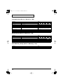
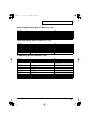
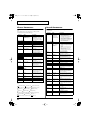
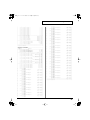
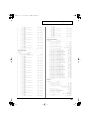
Parameter List
Thank you, and congratulations on your choice of the Roland
/
.
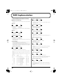
Parameter List............................................................. 2
Patch Parameter ............................................................................................ 2
Rhythm Set Parameter ................................................................................. 7
Performance Parameter ............................................................................. 10
Rhythm Group Parameter ......................................................................... 13
Sample Parameters ..................................................................................... 13
System Parameters...................................................................................... 14
Effects List ................................................................ 19
Multi-Effects Parameters ........................................................................... 19
Chorus Parameters ..................................................................................... 42
Reverb Parameters...................................................................................... 42
Input Effect Parameter ............................................................................... 43
Error Messages......................................................... 44
About MIDI................................................................. 45
MIDI Implementation ................................................ 46
Copyright © 2003 ROLAND CORPORATION
All rights reserved. No part of this publication may be reproduced in any form without
the written permission of ROLAND CORPORATION.
List_e 2 ページ 2003年5月15日 木曜日 午後1時35分
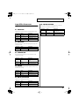
Parameter List
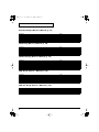
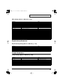
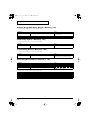
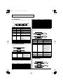
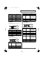
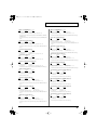
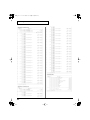
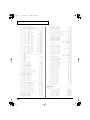
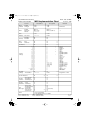
Patch Parameter
General Group (Owner’s Manual; p. 43)
Parameter
Patch Name
Patch Category
Patch Level
Patch Pan
Patch Priority
Octave Shift
Patch Coarse Tune
Patch Fine Tune
Stretch Tune Depth
Analog Feel
Cutoff Offset
Resonance Offset
Attack Time Offset
Release Time Offset
Velocity Sens Offset
Value
* Specify when writing.
Analog Feel Depth
space, A–Z, a–z, 0–9, ! ” # $ % & ’ ( ) * + , - . / : ; < = > ?
@[\]^_`{|}
0–127
L64–0–63R
LAST, LOUDEST
-3– +3
-48– +48
-50– +50
OFF, 1–3
0–127
-63– +63
-63– +63
-63– +63
-63– +63
-63– +63
Wave Group (Owner’s Manual; p. 45)
Parameter
Value
Wave Group
Wave Bank
INT, EXP, SAMP, MSAM
When the wave group is EXP: A–D, When the wave
group is SAMP: PRST, USER, CARD, When the wave
group is MSAM: USER, CARD
----, 1–1228 (The upper limit will depend on the wave
group.)
----, 1–1228 (The upper limit will depend on the wave
group.)
-6, 0, +6, +12
OFF, ON
OFF, ON
1–4
0–16
Wave No. L (Mono)
Wave Number L (Mono)
Wave No. R
Wave Number R
Wave Gain
Wave Tempo Sync
FXM Switch
FXM Color
FXM Depth
TMT Group (Owner’s Manual; p. 46)
Parameter
Structure Type 1 & 2, 3 & 4
Booster 1 & 2, 3 & 4
Key Fade Lower
Key Range Lower
Key Range Upper
Key Fade Upper
TMT Velocity Control
Velo Fade Lower
Velo Range Lower
Velo Range Upper
Velo Fade Upper
TMT Control Sw
2
Value
Booster Gain 1 & 2, 3 & 4
Keyboard Fade Width Lower
Keyboard Range Lower
Keyboard Range Upper
Keyboard Fade Width Upper
TMT Velocity Control Switch
Velocity Fade Width Lower
Velocity Range Lower
Velocity Range Upper
Velocity Fade Width Upper
TMT Control Switch
1–10
0, +6, +12, +18
0–127
C-1–UPPER
LOWER–G9
0–127
OFF, ON, RANDOM, CYCLE
0–127
1–UPPER
LOWER–127
0–127
OFF, ON
List_e 3 ページ 2003年5月15日 木曜日 午後1時35分
Parameter List
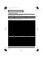
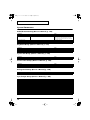
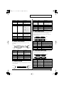
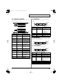
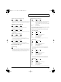
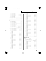
Pitch Group (Owner’s Manual; p. 49)
Parameter
Value
Tone Coarse Tune
Tone Fine Tune
Random Pitch Depth
-48– +48
-50– +50
0, 1, 2, 3, 4, 5, 6, 7, 8, 9, 10, 20, 30, 40, 50, 60, 70, 80, 90, 100,
200, 300, 400, 500, 600, 700, 800, 900, 1000, 1100, 1200
-200, -190, -180, -170, -160, -150, -140, -130, -120, -110,
-100, -90, -80, -70, -60, -50, -40, -30, -20, -10, 0, +10, +20,
+30, +40, +50, +60, +70, +80, +90, +100, +110, +120, +130,
+140, +150, +160, +170, +180, +190, +200
0– +48
-48–0
-63– +63
-63– +63
-63– +63
-100, -90, -80, -70, -60, -50, -40, -30, -20, -10, 0, +10, +20,
+30, +40, +50, +60, +70, +80, +90, +100
Pitch Key Follow
Bend Range Up
Bend Range Down
P-Env V-Sens
P-Env T1 V-Sens
P-Env T4 V-Sens
P-Env Time KF
Pitch Bend Range Up
Pitch Bend Range Down
Pitch Envelope Velocity Sensitivity
Pitch Envelope Time 1 Velocity Sensitivity
Pitch Envelope Time 4 Velocity Sensitivity
Pitch Envelope Time Key Follow
Pitch Env Group (Owner’s Manual; p. 50)
Parameter
P-Env Depth
P-Env Time1–4
P-Env Level0–4
Value
Pitch Envelope Depth
Pitch Envelope Time 1–4
Pitch Envelope Level 0–4
-12– +12
0–127
-63– +63
TVF Group (Owner’s Manual; p. 50)
Parameter
Value
Filter Type
Cutoff Frequency
Resonance
Cutoff Key Follow
Cutoff Frequency Key follow
Cutoff V-Curve
Cutoff V-Sens
Resonance V-Sens
F-Env V-Curve
F-Env V-Sens
F-Env T1 V-Sens
F-Env T4 V-Sens
Cutoff Frequency Velocity Curve
Cutoff Velocity Sensitivity
Resonance Velocity Sensitivity
TVF Envelope Velocity Curve
TVF Envelope Velocity Sensitivity
TVF Envelope Time 1 Velocity Sensitivity
TVF Envelope Time 4 Velocity Sensitivity
OFF, LPF BPF, HPF, PKG, LPF2, LPF3
0–127
0–127
-200, -190, -180, -170, -160, -150, -140, -130, -120, -110,
-100, -90, -80, -70, -60, -50, -40, -30, -20, -10, 0, +10, +20,
+30, +40, +50, +60, +70, +80, +90, +100, +110, +120, +130,
+140, +150, +160, +170, +180, +190, +200
FIXED, 1–7
-63– +63
-63– +63
FIXED, 1–7
-63– +63
-63– +63
-63– +63
TVF Env Group (Owner’s Manual; p. 52)
Value
Parameter
F-Env Depth
F-Env Time KF
TVF Envelope Depth
TVF Envelope Time Key Follow
F-Env Time1–4
F-Env Level 0–4
TVF Envelope Time 1–4
TVF Envelope Level 0–4
-63– +63
-100, -90, -80, -70, -60, -50, -40, -30, -20, -10, 0, +10, +20,
+30, +40, +50, +60, +70, +80, +90, +100
0–127
0–127
3
List_e 4 ページ 2003年5月15日 木曜日 午後1時35分
Parameter List
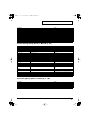
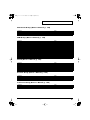
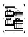
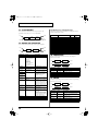
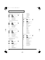
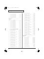
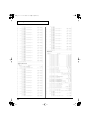
TVA Group (Owner’s Manual; p. 53)
Parameter
Tone Level
Level V-Curve
Level V-Sens
Bias Level
Bias Position
Bias Direction
Tone Pan
Pan Key follow
Random Pan Depth
Alter Pan Depth
Value
TVA Level Velocity Curve
TVA Level Velocity Sensitivity
Alternate Pan Depth
0–127
FIXED, 1–7
-63– +63
-100, -90, -80, -70, -60, -50, -40, -30, -20, -10, 0, +10, +20,
+30, +40, +50, +60, +70, +80, +90, +100
C-1–G9
LOWER, UPPER, LO&UP, ALL
L64–0–63R
-100– +100
0–63
L63–0–63R
TVA Env Group (Owner’s Manual; p. 54)
Parameter
Value
A-Env T1 V-Sens
A-Env T4 V-Sens
A-Env Time KF
TVA Envelope Time 1 Velocity Sensitivity
TVA Envelope Time 4 Velocity Sensitivity
TVA Envelope Time Key Follow
A-Env Time1–4
A-Env Level1–3
TVA Envelope Time 1–4
TVA Envelope Level 1–3
-63– +63
-63– +63
-100, -90, -80, -70, -60, -50, -40, -30, -20, -10, 0, +10, +20,
+30, +40, +50, +60, +70, +80, +90, +100
0–127
0–127
Output Group (Owner’s Manual; p. 55)
Parameter
Patch Out Assign
Tone Out Assign
Tone Out Level
Tone Chorus Send (Send Level
(Output=MFX))
Tone Reverb Send (Send Level
(Output=MFX))
Tone Chorus Send (Send Level
(Output=non MFX))
Tone Reverb Send (Send Level
(Output=non MFX))
Value
Patch Output Assign
Tone Output Assign
Tone Output Level
Tone Chorus Send Level
MFX, A, B, 1–4, TONE
MFX, A, B, 1–4
0–127
0–127
Tone Reverb Send Level
0–127
Tone Chorus Send Level
0–127
Tone Reverb Send Level
0–127
LFO1/2 Group (Owner’s Manual; p. 56)
Value
Parameter
Waveform
LFO1/LFO2 Waveform
Rate
Rate Detune
Offset
Delay Time
Delay Time KF
LFO1/LFO2 Rate
LFO1/LFO2 Rate Detune
LFO1/LFO2 Offset
LFO1/LFO2 Delay Time
LFO1/LFO2 Delay Time Key Follow
Fade Mode
Fade Time
Key Trigger
Pitch Depth
TVF Depth
TVA Depth
Pan Depth
LFO1/LFO2 Fade Mode
LFO1/LFO2 Fade Time
LFO1/LFO2 Key Trigger
LFO1/LFO2 Pitch Depth
LFO1/LFO2 TVF Depth
LFO1/LFO2 TVA Depth
LFO1/LFO2 Pan Depth
4
SIN, TRI, SAW-U, SAW-D, SQR, RND, BND-U, BND-D,
TRP S&H, CHAOS, VSIN, STEP
0–127, Note
0–127
-100, -50, 0, +50, +100
0–127
-100, -90, -80, -70, -60, -50, -40, -30, -20, -10, 0, +10, +20,
+30, +40, +50, +60, +70, +80, +90, +100
ON <, ON >, OFF <, OFF >
0–127
OFF, ON
-63– +63
-63– +63
-63– +63
-63– +63
List_e 5 ページ 2003年5月15日 木曜日 午後1時35分
Parameter List
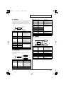
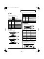
Step LFO Group (Owner’s Manual; p. 57)
Parameter
Step Type
Step 1–16
Value
LFO Step Type
LFO Step1–16
TYPE 1, TYPE 2
-36– +36
Solo/Porta Group (Owner’s Manual; p. 58)
Parameter
Value
Mono/Poly
Legato Switch
Legato Retrigger
Portamento Switch
Portamento Mode
Portamento Type
Portamento Start
Portamento Time
MONO, POLY
OFF, ON
OFF, ON
OFF, ON
NORMAL, LEGATO
RATE, TIME
PITCH, NOTE
0–127
Legato Retrigger Switch
Misc Group (Owner’s Manual; p. 60)
Parameter
Value
Tone Delay Mode
Tone Delay Time
Tone Env Mode
Tone Rx Bender
Tone Rx Expression
Tone Rx Hold-1
Tone Rx Pan Mode
Tone Redamper Sw
NORM, HOLD, OFF-N, OFF-D
0–127, Note
NO SUS, SUST
OFF, ON
OFF, ON
OFF, ON
CONT, K-ON
OFF, ON
Tone Receive Pitch Bend Switch
Tone Receive Expression Switch
Tone Receive Hold Switch
Tone Receive Pan Mode
Tone Redamper Switch
CTRL 1–4 Group (Owner’s Manual; p. 61)
Parameter
Value
Matrix Control 1–4 Source
OFF, CC01–31, 33–95, PITCH BEND, AFTERTOUCH,
SYS CTRL1–SYS CTRL4, VELOCITY, KEYFOLLOW,
TEMPO, LFO1, LFO2, PITCH ENV, TVF ENV, TVA
ENV
OFF, PITCH, CUTOFF, RESONANCE, LEVEL, PAN,
OUTPUT LEVEL, CHORUS SEND, REVERB SEND,
LFO1 PITCH DEPTH, LFO2 PITCH DEPTH, LFO1 TVF
DEPTH, LFO2 TVF DEPTH, LFO1 TVA DEPTH, LFO2
TVA DEPTH, LFO1 PAN DEPTH, LFO2 PAN DEPTH,
LFO1 RATE, LFO2 RATE, PIT ENV A-TIME, PIT ENV
D-TIME, PIT ENV R-TIME, TVF ENV A-TIME, TVF
ENV D-TIME, TVF ENV R-TIME, TVA ENV A-TIME,
TVA ENV D-TIME, TVA ENV R-TIME, TMT, FXM
DEPTH, MFX CTRL1, MFX CTRL2, MFX CTRL3, MFX
CTRL4, TIME
-63– +63
OFF, ON, REVERSE
CTRL Destination 1–4
Matrix Control Destination 1–4
CTRL Sens 1–4
CTRL Switch 1–4
Matrix Control Sens 1–4
Tone Control Switch 1–4
5
List_e 6 ページ 2003年5月15日 木曜日 午後1時35分
Parameter List
Effect Group (Owner’s Manual; p. 175)
Parameter
Value
MFX
Type
Multi-Effects Type
MFX Output Level
MFX Chorus Send Level
MFX Reverb Send Level
MFX Output Assign
Source 1–4
Multi-Effects Output Level
Multi-Effects Chorus Send Level
Multi-Effects Reverb Send Level
Multi-Effects Output Assign
Multi-Effects Control Source 1–4
Destination 1–4
Sens 1–4
Chorus
Chorus Type
Chorus Output Select
Chorus Level
Chorus Output Assign
Reverb
Reverb Type
Multi-Effects Control Destination 1–4
Multi-Effects Control Sens 1–4
Reverb Level
Reverb Output Assign
6
00 THROUGH–77 CHORUS->FLANGER (Fantom-S),
78 SYMPATHETIC RESONANCE (Fantom-S88)
0–127
0–127
0–127
A, B
OFF, CC01–31, 33–95, PITCH BEND, AFTERTOUCH,
SYS CTRL1–SYS CTRL4
-63– +63
0 (Off), 1 (Chorus), 2 (Delay), 3 (GM2 Chorus)
MAIN, REV, M+R
0–127
A, B
0 (Off), 1 (Reverb), 2 (SRV Room), 3 (SRV Hall), 4 (SRV
Plate), 5 (GM2 Reverb)
0–127
A, B
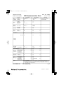
List_e 7 ページ 2003年5月15日 木曜日 午後1時35分
Parameter List
Rhythm Set Parameter
General Group (Owner’s Manual; p. 67)
Parameter
Rhythm Set Name
Value
* Specify when writing.
Rhythm Tone Name
Rhythm Level
Assign Type
Mute Group
Tone Env Mode
Tone Pitch Bend Range
Tone Receive Expression
Tone Receive Hold-1
Tone Receive Pan Mode
One Shot Mode
Aftertouch Time Ctrl Sens
Rhythm Set Level
Rhythm Tone Envelope Mode
Rhythm Tone Pitch Bend Range
Rhythm Tone Receive Expression Switch
Rhythm Tone Receive Hold-1 Switch
Rhythm Tone Receive Pan Mode
Aftertouch Time Control Sensitivity
space, A–Z, a–z, 0–9, ! ” # $ % & ’ ( ) * + , - . / : ; < = > ?
@[\]^_`{|}
space, A–Z, a–z, 0–9, ! ” # $ % & ’ ( ) * + , - . / : ; < = > ?
@[\]^_`{|}
0–127
MULTI, SINGLE
OFF, 1–31
NO-SUS, SUSTAIN
0–48
OFF, ON
OFF, ON
CONTINUOUS, KEY-ON
OFF, ON
-63– +63
Wave Group (Owner’s Manual; p. 68)
Parameter
Value
Wave Group
Wave Bank
INT, EXP, SAMP, MSAM
When the wave group is EXP: A–D, When the wave
group is SAMP: PRST, USER, CARD, When the wave
group is MSAM: USER, CARD
----, 1–1228 (The upper limit will depend on the wave
group.)
----, 1–1228 (The upper limit will depend on the wave
group.)
-6, 0, +6, +12
OFF, ON
OFF, ON
1–4
0–16
Wave No. L (Mono)
Wave Number L (Mono)
Wave No. R
Wave Number R
Wave Gain
Wave Tempo Sync
FXM Switch
FXM Color
FXM Depth
WMT Group (Owner’s Manual; p. 70)
Parameter
Value
Wave Coarse Tune
Wave Fine Tune
Wave Level
Wave Pan
Wave Rnd Pan Sw
Wave Alter Pan Sw
WMT Velocity Control
Velo Fade Lower
Velo Range Lower
Velo Range Upper
Velo Fade Upper
-48– +48
-50– +50
0–127
L64–0–63R
OFF, ON
OFF, ON, REVS
OFF, ON, RANDOM
0–127
1–UPPER
LOWER–127
0–127
Wave Random Pan Switch
Wave Alternate Pan Switch
Velocity Control Switch
Velocity Fade Width Lower
Velocity Range Lower
Velocity Range Upper
Velocity Fade Width Upper
Pitch Group (Owner’s Manual; p. 71)
Value
Parameter
Tone Coarse Tune
Tone Fine Tune
Tone Random Pitch Depth
Rhythm Tone Coarse Tune
Rhythm Tone Fine Tune
C-1–G9
-50– +50
0, 1, 2, 3, 4, 5, 6, 7, 8, 9, 10, 20, 30, 40, 50, 60, 70, 80, 90, 100,
200, 300, 400, 500, 600, 700, 800, 900, 1000, 1100, 1200
7
List_e 8 ページ 2003年5月15日 木曜日 午後1時35分
Parameter List
Pitch Env Group (Owner’s Manual; p. 71)
Parameter
P-Env Depth
P-Env V-Sens
P-Env T1 V-Sens
P-Env T4 V-Sens
P-Env Time1–4
P-Env Level 0–4
Value
Pitch Envelope Depth
Pitch Envelope Velocity Sensitivity
Pitch Envelope Time 1 Velocity Sensitivity
Pitch Envelope Time 4 Velocity Sensitivity
Pitch Envelope Time 1–4
Pitch Envelope Level 0–4
-12– +12
-63– +63
-63– +63
-63– +63
0–127
-63– +63
TVF Group (Owner’s Manual; p. 72)
Parameter
Value
Filter Type
Cutoff Frequency
Resonance
Cutoff V-Curve
Cutoff V-Sens
Resonance V-Sens
OFF, LPF BPF, HPF, PKG, LPF2, LPF3
0–127
0–127
FIXED, 1–7
-63– +63
-63– +63
Cutoff Frequency Velocity Curve
Cutoff Velocity Sensitivity
Resonance Velocity Sensitivity
TVF Env Group (Owner’s Manual; p. 73)
Parameter
F-Env Depth
F-Env V-Curve
F-Env V-Sens
F-Env T1 V-Sens
F-Env T4 V-Sens
F-Env Time1–4
F-Env Level0–4
Value
TVF Envelope Depth
TVF Envelope Velocity Curve
TVF Envelope Velocity Sensitivity
TVF Envelope Time 1 Velocity Sensitivity
TVF Envelope Time 4 Velocity Sensitivity
TVF Envelope Time 1–4
TVF Envelope Level 0–4
-63– +63
FIX, 1–7
-63– +63
-63– +63
-63– +63
0–127
0–127
TVA Group (Owner’s Manual; p. 74)
Value
Parameter
Tone Level
Level V-Curve
Level V-Sens
Tone Pan
Random Pan Depth
Alternate Pan Depth
Rhythm Tone level
Level Velocity Curve
Level Velocity Sensitivity
Rhythm Tone Pan
0–127
FIXED, 1–7
-63– +63
L64–0–63R
0–63
L63–0–63R
TVA Env Group (Owner’s Manual; p. 74)
Value
Parameter
A-Env T1 V-Sens
A-Env T4 V-Sens
A-Env Time1–4
A-Env Level1–3
8
TVA Envelope Time 1 Velocity Sensitivity
TVA Envelope Time 4 Velocity Sensitivity
TVA Envelope Time 1–4
TVA Envelope Level 1–3
-63– +63
-63– +63
0–127
0–127
List_e 9 ページ 2003年5月15日 木曜日 午後1時35分
Parameter List
Output Group (Owner’s Manual; p. 75)
Parameter
Rhythm Out Assign
Tone Out Assign
Tone Out Level
Tone Chorus Send (Send Level
(Output=MFX))
Tone Reverb Send (Send Level
(Output=MFX))
Tone Chorus Send (Send Level
(Output=non MFX))
Tone Reverb Send (Send Level
(Output=non MFX))
Value
Rhythm Output Assign
Tone Output Assign
Tone Output Level
Tone Chorus Send Level
MFX, A, B, 1–4, TONE
MFX, A, B, 1–4
0–127
0–127
Tone Reverb Send Level
0–127
Tone Chorus Send Level
0–127
Tone Reverb Send Level
0–127
Effect Group (Owner’s Manual; p. 175)
Parameter
Value
MFX
Type
Multi-Effects Type
MFX Output Level
MFX Chorus Send Level
MFX Reverb Send Level
MFX Output Assign
Source 1–4
Multi-Effects Output Level
Multi-Effects Chorus Send Level
Multi-Effects Reverb Send Level
Multi-Effects Output Assign
Multi-Effects Control Source 1–4
Destination 1–4
Sens 1–4
Chorus
Chorus Type
Chorus Output Select
Chorus Level
Chorus Output Assign
Reverb
Reverb Type
Multi-Effects Control Destination 1–4
Multi-Effects Control Sens 1–4
Reverb Level
Reverb Output Assign
00 THROUGH–77 CHORUS->FLANGER (Fantom-S),
78 SYMPATHETIC RESONANCE (Fantom-S88)
0–127
0–127
0–127
A, B
OFF, CC01–31, 33–95, PITCH BEND, AFTERTOUCH,
SYS CTRL1–SYS CTRL4
-63– +63
0 (Off), 1 (Chorus), 2 (Delay), 3 (GM2 Chorus)
MAIN, REV, M+R
0–127
A, B
0 (Off), 1 (Reverb), 2 (SRV Room), 3 (SRV Hall), 4 (SRV
Plate), 5 (GM2 Reverb)
0–127
A, B
9
List_e 10 ページ 2003年5月15日 木曜日 午後1時35分
Parameter List
Performance Parameter
General Group (Owner’s Manual; p. 96)
Parameter
Performance Name
Value
* Specify when writing.
space, A–Z, a–z, 0–9, ! ” # $ % & ’ ( ) * + , - . / : ; < = > ?
@[\]^_`{|}
Part View Group (Owner’s Manual; p. 84)
Parameter
[1 (Level/Pan)]
Patch Type
Patch Bank
Patch Number
Keyboard Switch
Solo Switch
Mute Switch
Part Level
Part Pan
[2 (Output Effect)]
Part Output Assign
Part Output MFX Select
Part Output Level
Part Chorus Send Level
Part Reverb Send Level
MFX1–3 Source
Chorus Source
Reverb Source
[3 (Pitch)]
Part Octave Shift
Part Coarse Tune
Part Fine Tune
Part Mono/Poly
Part Legato Switch
Part Pitch Bend Range
Part Portamento Switch
Part Portamento Time
[4 (Offset)]
Part Cutoff Offset
Part Resonance Offset
Part Attack Time Offset
Part Release Time Offset
Part Decay Time Offset
[5 (Key Range)]
Keyboard Range Lower
Keyboard Range Upper
Part Velocity Sens Offset
Part Vibrato Rate
Part Vibrato Depth
Part Vibrato Delay
Voice Reserve
[6 (Scale Tune)]
C–B
[7 (External)]
Receive Switch
Receive Channel
External Bank Select MSB
External Bank Select LSB
External Program Number
External Level
External Pan
10
Value
Patch, Rhythm
USER, PR-A–E (F;Fantom-S88), GM, CARD, XP-A–D
001–
OFF, ON
OFF, ON
OFF, ON
0–127
L64–0–63R
MFX, A, B, 1–4, PATCH
1–3 (MFX-1–MFX-3)
0–127
0–127
0–127
OFF, ON
OFF, ON
OFF, ON
-3– +3
-48– +48
-50– +50
MONO, POLY, PATCH
OFF, ON, PATCH
0–24, PATCH
OFF, ON, PATCH
0–127, PATCH
-64– +63
-64– +63
-64– +63
-64– +63
-64– +63
C-1–UPPER
LOWER–G9
-63– +63
-64– +63
-64– +63
-64– +63
0–63, FULL
Part Scale Tune C–B
External Program Change Number
-64– +63
OFF, ON
1–16
0–127, OFF
0–127
1–128, OFF
0–127, OFF
L64–0–63R, OFF
List_e 11 ページ 2003年5月15日 木曜日 午後1時35分
Parameter List
Parameter
[8 (MIDI Filter)]
Program Change
Bank Select
Pitch Bend
Polyphonic Key Pressure
Channel Pressure
Modulation
Volume
Pan
Expression
Hold-1
Phase Lock
Velocity Curve
Value
Receive Program Change Switch
Receive Bank Select Switch
Receive Pitch Bend Switch
Receive Polyphonic Key Pressure Switch
Receive Channel Pressure Switch
Receive Modulation Switch
Receive Volume Switch
Receive Pan Switch
Receive Expression Switch
Receive Hold 1 Switch
Phase Lock Switch
OFF, ON
OFF, ON
OFF, ON
OFF, ON
OFF, ON
OFF, ON
OFF, ON
OFF, ON
OFF, ON
OFF, ON
OFF, ON
OFF, 1–4
Control Setting Group (Owner’s Manual; p. 91)
Parameter
Ctrl Switch
Control Bender
Control Aftertouch
Control Modulation
Control Hold Pedal
Control Pedal
Control D Beam
Control Knob 1–4
D Beam (Pad Trigger)
Pad Number
Pad Velocity
Pad Control Mode
D Beam (Assignable)
Type
Value
Control Pitch Bend Switch
Control Aftertouch Switch
Control Modulation Switch
Control Hold Pedal Switch
Control Pedal Switch
Control D Beam Switch
Control Knob Switch
OFF, ON
OFF, ON
OFF, ON
OFF, ON
OFF, ON
OFF, ON
OFF, ON
1–16
1–127
MOMENTARY, LATCH
Assignable Type
Range Min
Range Max
Knob
Knob 1–4 Assign
CC01–31, 33–95, Bend Up, Bend Down, Start/Stop, Tap
Tempo, Arp Grid, Arp Duration, Arp Motif, Arp Octave
Up, Arp Octave Down
0–127
0–127
Realtime Control Knob Assign 1–4
CC01–31, 33–95, Pitch Bend, Aftertouch, Arp Style, Arp
Grid, Arp Duration, Arp Motif, Chord Form, Master
Level
Switch
Switch 1/2 Assign
Assignable Switch 1/2
Transpose Down, Transpose Up, Tap Tempo, Mono/
Poly, Portamento, Hold, MFX1–3 Sw, Chorus Sw, Reverb Sw, Mastering Sw, Loop, Rhythm Start/Stop
Tempo
Recommended Tempo
MFX Ctrl Ch
MFX1–3 Control Channel
20–250
1–16, OFF
Pad Setting Group (Owner’s Manual; p. 136)
Value
Parameter
Pad Set
Base
Pad Part
Note
Velocity
Pad Base Note
Pad Note
Pad Velocity
User, Note, Rhythm
C-1–G9
1–16
C-1–G9
REAL, 1–127
11
List_e 12 ページ 2003年5月15日 木曜日 午後1時35分
Parameter List
Arpeggio Group (Owner’s Manual; p. 104)
Parameter
Arp/Rhy Switch
Arp Grid
Arp Duration
Arpeggio Switch
Arpeggio Hold
Arpeggio Style
Arpeggio Motif
Value
Arpeggio/Rhythm Switch
Arpeggio Grid
Arpeggio Duration
Arpeggio Velocity
Arpeggio Part
Arpeggio Octave Range
Arpeggio Accent Rate
OFF, ON
1/4 ( ), 1/8 (
), 1/8 (
) L, 1/8 (
) H, 1/12 (
),
1/16 ( ), 1/16 ( ) L, 1/16 ( ) H, 1/24 ( )
30, 40, 50, 60, 70, 80, 90,100, 120, FULL
OFF, ON
OFF, ON
U001–U128, P001–P128
Up (L), Up (L&H), Up (_), Down (L), Down (L&H),
Down (_), Up&Down, Up&Down (L&H),
Up&Down (_), Random (L), Random (_), Phrase
REAL, 1–127
1–16
-3– +3
0–100
Rhythm Group (Owner’s Manual; p. 112)
Parameter
Arp/Rhy Switch
Rhythm Pattern Grid
Value
Arpeggio/Rhythm Switch
Rhythm Pattern Duration
Rhythm Pattern Switch
Rhythm Pattern Velocity
Rhythm Pattern Accent Rate
Rhythm Group Number
OFF, ON
1/4 ( ), 1/8 (
), 1/8 (
Chord Memory Group (Owner’s Manual; p. 110)
Parameter
Value
Chord Switch
Chord Form
OFF, ON
U01–U64, P01–P64
12
) L, 1/8 (
) H, 1/12 (
1/16 ( ), 1/16 ( ) L, 1/16 ( ) H, 1/24 (
30, 40, 50, 60, 70, 80, 90, 100, 120, FULL
OFF, ON
REAL, 1–127
0–100
U01–U32, P01–P32
)
),
List_e 13 ページ 2003年5月15日 木曜日 午後1時35分
Parameter List
Effect Group (Owner’s Manual; p. 178)
Parameter
MFX
Structure Type
MFX Type
MFX Output Level
MFX Chorus Send Level
MFX Reverb Send Level
MFX Output Assign
Source 1–4
Destination 1–4
Sens 1–4
MFX Control Channel
MFX-1–3 Source
Chorus
Chorus Type
Chorus Output Select
Chorus Level
Chorus Output Assign
Chorus Source
Reverb
Reverb Type
Value
Multi-Effects Type
Multi-Effects Output Level
Multi-Effects Chorus Send Level
Multi-Effects Reverb Send Level
Multi-Effects Output Assign
Multi-Effects Control Source 1–4
Multi-Effects Control Destination 1–4
Multi-Effects Control Sens 1–4
Multi-Effects Control Channel
Multi-Effects 1–3 Source
1–16
0–77 (Fantom-S88;78)
0–127
0–127
0–127
A, B
OFF, CC01–31, 33–95, PITCH BEND, AFTERTOUCH,
SYS CTRL1–SYS CTRL4
-63– +63
1–16, OFF
PRF, P1–P16
0 (Off), 1 (Chorus), 2 (Delay), 3 (GM2 Chorus)
MAIN, REV, MAIN+REV
0–127
A, B
PRF, P1–P16
0 (Off), 1 (Reverb) 2 (SRV Room), 3 (SRV Hall) 4 (SRV
Plate), 5 (GM2 Reverb)
0–127
A, B
PRF, P1–P16
Reverb Level
Reverb Output Assign
Reverb Source
Rhythm Group Parameter
Rhythm Group Group (Owner’s Manual; p. 116)
Value
Parameter
Recommended Rhy
Pad Mode
Rhy Ptn Number
Rhy Ptn Velocity
Pad Note
Pad Velocity
Recommended Rhythm Set
Rhythm Pattern Number
Rhythm Pattern Velocity
USER, PR-A–E (F;Fantom-S88), GM, CARD, XP-A–D
OFF, NOTE, PATTERN
U001–U256, P001–P256
REAL, 1–127
C-1–G9
REAL, 1–127
Sample Parameters
Sample Group (Owner’s Manual; p. 125)
Parameter
Value
Sample Name
space, A–Z, a–z, 0–9, ! ” # $ % & ’ ( ) * + , - . / : ; < = > ?
@[\]^_`{|}
FWD, ONE-SHOT, REV, REV-ONE
-50– +50
0 (C-1) –127 (G9)
5.00–300.00
TYPE01–TYPE10
0–255
0–255
0–255
Loop Mode
Loop Tune
Original Key
BPM
Time Stretch Type
Start Fine
Loop Start Fine
Loop End Fine
tempo
13
List_e 14 ページ 2003年5月15日 木曜日 午後1時35分
Parameter List
System Parameters
Pedal/D Beam Group (Owner’s Manual; p. 189)
Parameter
D Beam Sens
Control Pedal Assign
Value
D Beam Sensitivity
Control Pedal Polarity
Hold Pedal Polarity
Continuous Hold Pedal
0–127
CC01–31, 33–95, BEND-UP, BEND-DOWN, AFT, OCTUP, OCT-DOWN, START/STOP, PUNCH-I/O, TAPTEMPO, PROG-UP, PROG-DOWN, FAV-UP, FAVDOWN, ARP-RHY-SW, RHY-START-STOP, CHD-SW
STANDARD, REVERSE
STANDARD, REVERSE
OFF, ON
Keyboard Group (Owner’s Manual; p. 189)
Parameter
Keyboard Velocity
Keyboard Sens
Aftertouch Sens
Value
Keyboard Sensitivity
Aftertouch Sensitivity
REAL, 1–127
LIGHT, MEDIUM, HEAVY
0–100
System Ctrl Group (Owner’s Manual; p. 190)
Parameter
Sys Ctrl 1–4 Source
Value
System Control1–4 Source
OFF, CC01–31, 33–95, BEND, AFT
Screen Saver Group (Owner’s Manual; p. 190)
Parameter
Value
Screen Saver Type
Screen Saver Time
1–10
OFF, 5–60 min
Background Group (Owner’s Manual; p. 190)
Parameter
Value
Background Picture
1–10
Sync/Tempo Group (Owner’s Manual; p. 190)
Value
Parameter
Sync Mode
Sync Output
Tempo Override
Arp/Rhythm Sync Switch
MMC Mode
MMC Output
MTC Sync Output
MTC Frame Rate
MTC Offset Time Hour
MTC Offset Time Minute
MTC Offset Time Second
MTC Offset Time Frame
MTC Error Level
14
Sync Output switch
Arpeggio/Rhythm Sync Switch
MMC Output switch
MTC Sync Output switch
MASTER, SLAVE-MIDI, SLAVE-MTC, REMOTE
OFF, ON
OFF, ON
OFF, ON
MASTER, SLAVE
OFF, ON
OFF, ON
24, 25, 29N, 29D, 30
0–23 hours
0–59 minutes
0–59 seconds
0–29 frames
0 –10
List_e 15 ページ 2003年5月15日 木曜日 午後1時35分
Parameter List
Metronome Group (Owner’s Manual; p. 192)
Parameter
Value
Metronome Mode
OFF, PLAY-ONLY, REC-ONLY, PLAY&REC, ALWAYS
0–10
TYPE 1, TYPE 2, TYPE 3, TYPE 4
Metronome Level
Metronome Sound
MIDI Group (Owner’s Manual; p. 192)
Parameter
Device ID
Performance Control Channel
Kbd Patch Rx/Tx Ch
Pad Patch Rx/Tx Ch
Transmit Program Change
Transmit Bank Select
Transmit Active Sensing
Transmit Edit Data
Soft Through
Remote Keyboard Sw
Receive Program Change
Receive Bank Select
Receive Exclusive
Receive GM System On
Receive GM2 System On
Receive GS Reset
Value
Device ID Number
Keyboard Patch Receive/Transmit Channel
Pad Patch Receive/Transmit Channel
Transmit Program Change Switch
Transmit Bank Select Switch
Transmit Active Sensing Switch
Transmit Edit Data Switch
Soft Through Switch
Remote Keyboard Switch
Receive Program Change Switch
Receive Bank Select Switch
Receive System Exclusive Switch
Receive GM System On Switch
Receive GM2 System On Switch
Receive GS Reset Switch
17–32
1–16, OFF
1–16
1–16
OFF, ON
OFF, ON
OFF, ON
OFF, ON
OFF, ON
OFF, ON
OFF, ON
OFF, ON
OFF, ON
OFF, ON
OFF, ON
OFF, ON
Sound (Owner’s Manual; p. 193)
Parameter
Value
Local Switch
Master Tune
Master Level
Output Gain
Mix/Parallel
Master Key Shift
Patch Remain
OFF, ON
415.3–466.2 Hz
0–127
-12– +12 dB
MIX, PARALLEL
-24– +24
OFF, ON
Patch Remain Switch
Preview Group (Owner’s Manual; p. 194)
Parameter
Value
Preview Mode
Preview 1–4 Note Number
Preview 1–4 Velocity
SINGLE, CHORD, PHRASE
C-1–G9
OFF, 1–127
Scale Tune Group (Owner’s Manual; p. 194)
Parameter
Value
Scale Tune Switch
Patch Scale Tune for C–B
OFF, ON
-64– +63
15
List_e 16 ページ 2003年5月15日 木曜日 午後1時35分
Parameter List
Sampling Group (Owner’s Manual; p. 195)
Parameter
Value
Default File Type
Pre Sample Time
Trigger Level
Gap Time
External Source Select
Trimming Switch
Skip Back Time
WAV, AIFF
0–1000 ms
0–7
500, 1000, 1500, 2000 ms
LINE-L-R, LINE-L, MIC
OFF, ON
5s–40s
Startup Group (Owner’s Manual; p. 195)
Parameter
Value
Preset Default Load
Sample Default Load
Power Up Mode
SRX/RAM Mode
OFF, ON
OFF, ON
PATCH, PERFORMANCE
4 SRX/192MB Max, 2 SRX/288MB Max
System Information Group (Owner’s Manual; p. 195)
Parameter
Features
Memory Info
SRX Info
Version Info
Displays the main features of the Fantom-S.
Memory Information
SRX Information
Version Information
D Beam (Solo Synth) Group (Owner’s Manual; p. 100)
Parameter
Value
OSC1/2 Waveform
OSC1/2 Pulse Width
OSC1/2 Coarse Tune
OSC1/2 Fine Tune
OSC2 Level
OSC Sync Switch
Filter Type
Cutoff
Resonance
Level
Chorus Send Level
Reverb Send Level
LFO Rate
LFO Osc 1 Pitch Depth
LFO Osc 2 Pitch Depth
LFO Osc 1 Pulse Width Depth
LFO Osc 2 Pulse Width Depth
Range
SAW, SQR
0–127
-48– +48
-50– +50
0–127
OFF, ON
OFF, LPF, BPF, HPF, PKG
0–127
0–127
0–127
0–127
0–127
0–127
-63– +63
-63– +63
-63– +63
-63– +63
2 OCTAVE, 4 OCTAVE, 8 OCTAVE
16
Solo Synth Range
List_e 17 ページ 2003年5月15日 木曜日 午後1時35分
Parameter List
Mastering Effect Group (Owner’s Manual; p. 183)
Parameter
Value
HIGH/MID/LOW ATTACK
HIGH/MID/LOW RELEASE
HIGH/MID/LOW THRESHOLD
HIGH/MID/LOW RATIO
HIGH/MID/LOW LEVEL
Split Frequency High
Split Frequency Low
0–100 ms
50–5000 ms
-36–0 dB
1.00:1–INF:1 (INF: Infinity)
0–24 dB
2000–8000 Hz
200–800 Hz
Input Setting Group (Owner’s Manual; p. 118)
Parameter
Value
Input Select
Mix-In
Ext Output Assign
Ext Output Level
Ext Chorus Send Level
Ext Reverb Send Level
Input Effect Switch
Input Effect Type
LINE IN L/R, LINE IN L, MICROPHONE
ON, OFF
DRY, MFX
0–127
0–127
0–127
ON, OFF
EQ, ENHANCER, COMP, LIMITER, NOISE SUP, C
CANCELER
V-LINK Group (Owner’s Manual; p. 201)
Parameter
Note Tx Ch
Clip 1 Note No.
Play Speed Ctrl
Value
Note Transmit Channel
Clip 1 Note Number
Play Speed Control
Dissolve Time
Ctrl Tx Ch
Color Cb Ctrl
Control Transmit Channel
Color Cb Control
Color Cr Ctrl
Color Cr Control
Brightness Ctrl
Brightness Control
VFX Ctrl
VFX Control
PAD MODE
Local Sw
CLIP FILTER 1–32
Local Switch
1–16
0 (C-1)–127 (G9)
0.0-1.0-2.0, 0.5-1.0-2.0, 0.0-1.0-4.0, 0.5-1.0-4.0, 0.0-1.0-8.0,
0.5-1.0-8.0, 0.0-1.0-16.0, 0.5-1.0-16.0, 0.0-1.0-32.0, 0.5-1.032.0, 0.0-2.0-4.0, 0.0-4.0-8.0, 0.0 8.0-16.0, 0.0-16.0-32.0, 2.0-1.0-4.0, -6.0-1.0-8.0
OFF, CC1, CC5, CC7, CC10, CC11, CC71–74, CC91–93,
Channel Aftertouch
1–16
OFF, CC1, CC5, CC7, CC10, CC11, CC71–74, CC91–93,
Channel Aftertouch
OFF, CC1, CC5, CC7, CC10, CC11, CC71–74, CC91–93,
Channel Aftertouch
OFF, CC1, CC5, CC7, CC10, CC11, CC71–74, CC91–93,
Channel Aftertouch
OFF, CC1, CC5, CC7, CC10, CC11, CC71–74, CC91–93,
Channel Aftertouch
CLIP, PALETT
OFF, ON
OFF, ON
17
List_e 18 ページ 2003年5月15日 木曜日 午後1時35分
Parameter List
D Beam (Assignable) Group (Owner’s Manual; p. 98)
* If Patch mode is selected, this is saved as part of the system settings.
Parameter
Type
Value
Assignable Type
Range Min
Range Max
CC01–31, 33–95, Bend Up, Bend Down, Start/Stop, Tap
Tempo, Arp Grid, Arp Duration, Arp Motif, Arp Octave
Up, Arp Octave Down
0–127
0–127
Knob Group (Owner’s Manual; p. 101)
* If Patch mode is selected, this is saved as part of the system settings.
Parameter
Knob 1–4 Assign
Value
Realtime Control Knob Assign 1–4
CC01–31, 33–95, Pitch Bend, Aftertouch, Arp Style, Arp
Grid, Arp Duration, Arp Motif, Chord Form, Master
Level
Switch Group (Owner’s Manual; p. 102)
* If Patch mode is selected, this is saved as part of the system settings.
Parameter
Switch 1/2 Assign
Value
Assignable Switch 1/2
Transpose Down, Transpose¬ Up, Tap Tempo, Mono/
Poly, Portamento, Hold, MFX1–3 Sw, Chorus Sw, Reverb Sw, Mastering Sw, Loop, Rhythm Start/Stop
Pad Setting Group (Owner’s Manual; p. 136)
Value
Parameter
Pad Common Velo
Pad Sens
Aftertouch Sens
Roll Resolution
Pad Common Velocity
Pad Sensitivity
Aftertouch Sensitivity
REAL, 1–127
LIGHT, MEDIUM, HEAVY
0–100
1/4 ( ), 1/6 (
1/24 (
), 1/8 (
), 1/32 (
* If Patch mode is selected, this is saved as part of the system settings.
Value
Parameter
Pad Set
Base
Note
Velocity
18
Pad Base Note
Pad Note
Pad Velocity
), 1/12 (
), 1/48 (
User, Note, Rhythm
C-1–G9
C-1–G9
REAL, 1–127
)
), 1/16 (
),
List_e 19 ページ 2003年5月15日 木曜日 午後1時35分
Effects List
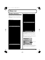
Multi-Effects Parameters
The multi-effects feature 78 (Fantom-S; 77) different kinds of effects.
Some of the effects consist of two or more different effects connected
in series.
Parameters marked with a sharp “#” can be controlled using a
specified controller (Two setting items will change simultaneously
for “#1” and “#2”).
51
52
53
54
55
SHUFFLE DELAY
3D DELAY
TIME CTRL DELAY
LONG TIME CTRL DELAY
TAPE ECHO
P.33
P.34
P.34
P.34
P.34
LO-FI (5 types)
56
57
58
59
60
LOFI NOISE
LOFI COMPRESS
LOFI RADIO
TELEPHONE
PHONOGRAPH
P.35
P.35
P.35
P.36
P.36
PITCH (3 types)
FILTER (10 types)
01
02
03
04
05
06
07
08
09
10
EQUALIZER
SPECTRUM
ISOLATOR
LOW BOOST
SUPER FILTER
STEP FILTER
ENHANCER
AUTO WAH
HUMANIZER
SPEAKER SIMULATOR
P.20
P.20
P.20
P.20
P.20
P.21
P.21
P.21
P.22
P.22
MODULATION (12 types)
11
12
13
14
15
16
17
18
19
20
21
22
PHASER
STEP PHASER
MULTI STAGE PHASER
INFINITE PHASER
RING MODULATOR
STEP RING MODULATOR
TREMOLO
AUTO PAN
STEP PAN
SLICER
ROTARY
VK ROTARY
P.22
P.22
P.23
P.23
P.23
P.23
P.24
P.24
P.24
P.24
P.25
P.25
CHORUS (12 types)
23
24
25
26
27
28
29
30
31
32
33
34
CHORUS
FLANGER
STEP FLANGER
HEXA-CHORUS
TREMOLO CHORUS
SPACE-D
3D CHORUS
3D FLANGER
3D STEP FLANGER
2BAND CHORUS
2BAND FLANGER
2BAND STEP FLANGER
P.25
P.26
P.26
P.26
P.26
P.27
P.27
P.27
P.28
P.28
P.28
P.29
61
62
63
PITCH SHIFTER
2VOICE PITCH SHIFTER
STEP PITCH SHIFTER
P.36
P.36
P.37
REVERB (2 types)
64
65
REVERB
GATED REVERB
P.37
P.37
COMBINATION (12 types)
66
67
68
69
70
71
72
73
74
75
76
77
OVERDRIVE → CHORUS
OVERDRIVE → FLANGER
OVERDRIVE → DELAY
DISTORTION → CHORUS
DISTORTION → FLANGER
DISTORTION → DELAY
ENHANCER → CHORUS
ENHANCER → FLANGER
ENHANCER → DELAY
CHORUS → DELAY
FLANGER → DELAY
CHORUS → FLANGER
P.38
P.38
P.38
P.38
P.38
P.38
P.39
P.39
P.39
P.39
P.40
P.40
5 PIANO (1 type)
78
SYMPATHETIC RESONANCE
(Fantom-S88 only)
P.40
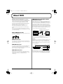
About Note
Some effect parameters (such as Rate or Delay Time) can be set in
terms of a note value.
Such parameters have a num/note switch that lets you specify
whether you will set the value as a note value or as a numerical
value.
If you want to set Rate (Delay Time) as a numerical value, set the
num/note switch to “Hz” (“msec”). If you want to set it as a note
value, set the num/note switch to “NOTE.”
DYNAMICS (8 types)
35
36
37
38
39
40
41
42
OVERDRIVE
DISTORTION
VS OVERDRIVE
VS DISTORTION
GUITAR AMP SIMULATOR
COMPRESSOR
LIMITER
GATE
P.29
P.29
P.29
P.30
P.30
P.30
P.30
P.31
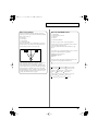
num/note switch
DELAY (13 types)
43
44
45
46
47
48
49
50
DELAY
LONG DELAY
SERIAL DELAY
MODULATION DELAY
3TAP PAN DELAY
4TAP PAN DELAY
MULTI TAP DELAY
REVERSE DELAY
P.31
P.31
P.31
P.32
P.32
P.32
P.33
P.33
If a parameter whose num/note switch is set to “NOTE” is
specified as a destination for multi-effect control, you will not be
able to use multi-effect control to control that parameter.
19
List_e 20 ページ 2003年5月15日 木曜日 午後1時35分
Effects List
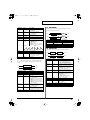
01: EQUALIZER
This is a four-band stereo equalizer (low, mid x 2, high).
fig.MFX-01
L in
4-Band EQ
L out
R in
4-Band EQ
R out
Parameter
Value
Description
Low Freq
Low Gain #
Mid1 Freq
200, 400 Hz
-15– +15 dB
200–8000 Hz
Mid1 Gain
Mid1 Q
-15– +15 dB
0.5, 1.0, 2.0, 4.0, 8.0
Mid2 Freq
200–8000 Hz
Mid2 Gain
Mid2 Q
-15– +15 dB
0.5, 1.0, 2.0, 4.0, 8.0
High Freq
High Gain #
Level #
2000, 4000, 8000 Hz
-15– +15 dB
0–127
Frequency of the low range
Gain of the low range
Frequency of the middle
range 1
Gain of the middle range 1
Width of the middle range 1
Set a higher value for Q to
narrow the range to be affected.
Frequency of the middle
range 2
Gain of the middle range 2
Width of the middle range 2
Set a higher value for Q to
narrow the range to be affected.
Frequency of the high range
Gain of the high range
Output Level
This is a stereo spectrum. Spectrum is a type of filter which modifies
the timbre by boosting or cutting the level at specific frequencies.
fig.MFX-02
Description
-60– +4 dB
These boost and cut each of the High,
Middle, and Low frequency ranges.
At -60 dB, the sound becomes inaudible. 0 dB is equivalent to the
input level of the sound.
OFF, ON
Anti Phase
Low Level
0–127
Anti Phase
Mid Sw
Anti Phase
Mid Level
Low Boost Sw
OFF, ON
Low Boost
Level
0–127
Level
0–127
Turns the Anti-Phase function on and
off for the Low frequency ranges.
When turned on, the counterchannel of stereo sound is inverted
and added to the signal.
Adjusts the level settings for the Low
frequency ranges.
Adjusting this level for certain frequencies allows you to lend emphasis to specific parts. (This is
effective only for stereo source.)
Settings of the Anti-Phase function
for the Middle frequency ranges
The parameters are the same as for
the Low frequency ranges.
Turns Low Booster on/off.
This emphasizes the bottom to create a heavy bass sound.
Increasing this value gives you a
heavier low end.
* Depending on the Isolator and filter settings this effect may be hard
to distinguish.
Output Level
0–127
OFF, ON
Boosts the volume of the lower range, creating powerful lows.
fig.MFX-04
L in
Low Boost
2-Band EQ
L out
R in
Low Boost
2-Band EQ
R out
L out
Spectrum
R in
Value
04: LOW BOOST
02: SPECTRUM
L in
Parameter
Boost/
Cut Low #
Boost/
Cut Mid #
Boost/
Cut High #
Anti Phase
Low Sw
R out
Spectrum
Parameter
Value
Description
Band1 (250Hz)
Band2 (500Hz)
Band3 (1000Hz)
Band4 (1250Hz)
Band5 (2000Hz)
Band6 (3150Hz)
Band7 (4000Hz)
Band8 (8000Hz)
Q
-15– +15 dB
Gain of each frequency band
Level #
0–127
Parameter
Value
Description
Boost
Frequency #
Boost Gain #
50–125 Hz
Boost Width
WIDE, MID,
NARROW
-15– +15 dB
-15– +15 dB
0–127
Center frequency at which the lower
range will be boosted
Amount by which the lower range
will be boosted
Width of the lower range that will be
boosted
Gain of the low frequency range
Gain of the high frequency range
Output level
Low Gain
High Gain
Level
0.5, 1.0, 2.0, 4.0, 8.0
Simultaneously adjusts the
width of the adjusted ranges for
all the frequency bands.
Output Level
0– +12 dB
05: SUPER FILTER
This is a filter with an extremely sharp slope. The cutoff frequency
can be varied cyclically.
fig.MFX-05
03: ISOLATOR
This is an equalizer which cuts the volume greatly, allowing you to
add a special effect to the sound by cutting the volume in varying
ranges.
fig.MFX-03
L in
Isolator
Low Boost
L out
R in
Isolator
Low Boost
R out
20
L in
Super Filter
L out
R in
Super Filter
R out
Parameter
Value
Description
Filter Type
LPF, BPF,
HPF, NOTCH
Filter type
Frequency range that will pass
through each filter
LPF: frequencies below the cutoff
BPF: frequencies in the region of the
cutoff
HPF: frequencies above the cutoff
NOTCH: frequencies other than the
region of the cutoff
List_e 21 ページ 2003年5月15日 木曜日 午後1時35分
Effects List
Parameter
Value
Description
Filter Slope
-12, -24, -36 dB
Amount of attenuation per octave
-36 dB: extremely steep
-24 dB: steep
-12 dB: gentle
Cutoff frequency of the filter
Increasing this value will raise the
cutoff frequency.
Filter resonance level
Increasing this value will emphasize
the region near the cutoff frequency.
Amount of boost for the filter output
On/off switch for cyclic change
Filter
Cutoff #
0–127
Filter
Resonance #
0–127
Filter Gain
Modulation
Sw
Modulation
Wave
0– +12 dB
OFF,ON
TRI, SQR,
SIN, SAW1,
SAW2
SAW1
How the cutoff frequency will be modulated
TRI: triangle wave
SQR: square wave
SIN: sine wave
SAW1: sawtooth wave (upward)
SAW2: sawtooth wave (downward)
SAW2
07: ENHANCER
Controls the overtone structure of the high frequencies, adding
sparkle and tightness to the sound.
fig.MFX-07
L in
2-Band
EQ
L out
Mix
R out
Mix
2-Band
EQ
Enhancer
R in
Enhancer
Parameter
Value
Description
Sens #
Mix #
0–127
0–127
Low Gain
High Gain
Level
-15– +15 dB
-15– +15 dB
0–127
Sensitivity of the enhancer
Level of the overtones generated by the enhancer
Gain of the low range
Gain of the high range
Output Level
08: AUTO WAH
Rate #
Depth
Attack #
0.05–10.00 Hz,
note
0–127
0–127
Level
0–127
Rate of modulation
Depth of modulation
Speed at which the cutoff frequency
will change
This is effective if Modulation Wave
is SQR, SAW1, or SAW2.
Output level
06: STEP FILTER
Cyclically controls a filter to create cyclic change in timbre.
fig.MFX-08
L in
Auto Wah
2-Band EQ
L out
R in
Auto Wah
2-Band EQ
R out
Parameter
Value
Description
Filter Type
LPF, BPF
Manual #
0–127
Peak
0–127
Sens #
0–127
Polarity
UP, DOWN
Rate #
Depth #
Phase #
0.05–10.00 Hz,
note
0–127
0–180 deg
Type of filter
LPF: The wah effect will be applied
over a wide frequency range.
BPF: The wah effect will be applied
over a narrow frequency range.
Adjusts the center frequency at which
the effect is applied.
Adjusts the amount of the wah effect
that will occur in the range of the center
frequency.
Set a higher value for Q to narrow
the range to be affected.
Adjusts the sensitivity with which the
filter is controlled.
Sets the direction in which the frequency will change when the auto-wah filter
is modulated.
UP: The filter will change toward a
higher frequency.
DOWN: The filter will change toward a lower frequency.
Frequency of modulation
Low Gain
High Gain
Level
-15– +15 dB
-15– +15 dB
0–127
This is a filter whose cutoff frequency can be modulated in steps.
You can specify the pattern by which the cutoff frequency will
change.
fig.MFX-06
L in
Step Filter
L out
R in
Step Filter
R out
Parameter
Value
Description
Step 01–16
Rate #
0–127
0.05–10.00 Hz,
note
0–127
Cutoff frequency at each step
Rate of modulation
Attack #
Filter Type
LPF, BPF,
HPF, NOTCH
Filter Slope
-12, -24, -36 dB
Filter
Resonance #
0–127
Filter Gain
Level
0– +12 dB
0–127
Speed at which the cutoff frequency
changes between steps
Filter type
Frequency range that will pass
through each filter
LPF: frequencies below the cutoff
BPF: frequencies in the region of the
cutoff
HPF: frequencies above the cutoff
NOTCH: frequencies other than the
region of the cutoff
Amount of attenuation per octave
-12 dB: gentle
-24 dB: steep
-36 dB: extremely steep
Filter resonance level
Increasing this value will emphasize
the region near the cutoff frequency.
Amount of boost for the filter output
Output level
Depth of modulation
Adjusts the degree of phase shift of the
left and right sounds when the wah effect is applied.
Gain of the low range
Gain of the high range
Output Level
21
List_e 22 ページ 2003年5月15日 木曜日 午後1時35分
Effects List
09: HUMANIZER
Type
Cabinet
Speaker
Adds a vowel character to the sound, making it similar to a human
voice.
Microphone
BUILT-IN 2
BUILT-IN 3
BUILT-IN 4
BUILT-IN 5
BG STACK 1
BG STACK 2
MS STACK 1
MS STACK 2
METAL STACK
2-STACK
3-STACK
open back enclosure
open back enclosure
open back enclosure
open back enclosure
sealed enclosure
large sealed enclosure
large sealed enclosure
large sealed enclosure
large double stack
large double stack
large triple stack
12 x 2
12 x 2
12 x 2
12 x 2
12 x 2
12 x 2
12 x 4
12 x 4
12 x 4
12 x 4
12 x 4
condenser
condenser
condenser
condenser
condenser
condenser
condenser
condenser
condenser
condenser
condenser
fig.MFX-09
L in
L out
Overdrive
2-Band
EQ
Formant
Pan L
Pan R
R in
R out
Parameter
Value
Description
Drive Sw
Drive #
OFF, ON
0–127
Vowel1
Vowel2
Rate #
a, e, i, o, u
a, e, i, o, u
0.05–10.00 Hz,
note
0–127
OFF, ON
Turns Drive on/off.
Degree of distortion
Also changes the volume.
Selects the vowel.
Depth #
Input Sync
Sw
Input Sync
Threshold
Manual #
0–127
Low Gain
High Gain
Pan #
Level
-15– +15 dB
-15– +15 dB
L64–63R
0–127
0–100
11: PHASER
Frequency at which the two vowels
switch
Effect depth
Determines whether the LFO for
switching the vowels is reset by the input signal (ON) or not (OFF).
Volume level at which reset is applied
Point at which Vowel 1/2 switch
49 or less: Vowel 1 will have a longer duration.
50: Vowel 1 and 2 will be of equal
duration.
51 or more: Vowel 2 will have a
longer duration.
Gain of the low frequency range
Gain of the high frequency range
Stereo location of the output
Output level
10: SPEAKER SIMULATOR
A phase-shifted sound is added to the original sound and
modulated.
fig.MFX-11
L in
Phaser
Mix
Mix
R in
Phaser
L out
R in
Speaker
R out
Parameter
Value
Description
Speaker Type
Mic Setting
(See the table right.)
1, 2, 3
Type of speaker
Adjusts the location of the mic
that is recording the sound of
the speaker.
This can be adjusted in
three steps, with the mic
becoming more distant in
the order of 1, 2, and 3.
Volume of the microphone
Volume of the direct sound
Output Level
Mic Level #
Direct Level #
Level #
0–127
0–127
0–127
Description
4-STAGE, 8-STAGE,
12-STAGE
0–127
Number of stages in the
phaser
Adjusts the basic frequency
from which the sound will be
modulated.
Frequency of modulation
Depth of modulation
Selects whether the left and
right phase of the modulation
will be the same or the opposite.
INVERSE: The left and
right phase will be opposite. When using a mono
source, this spreads the
sound.
SYNCHRO: The left and
right phase will be the
same. Select this when inputting a stereo source.
Amount of feedback
Adjusts the proportion of the
phaser sound that is fed back
into the effect. Negative (-)
settings will invert the phase.
Level of the phase-shifted
sound
Gain of the low range
Gain of the high range
Output Level
Manual #
Rate #
Depth
Polarity
0.05–10.00 Hz, note
0–127
INVERSE,
SYNCHRO
Resonance #
Cross
Feedback
0–127
-98– +98 %
Mix #
0–127
Low Gain
High Gain
Level
-15– +15 dB
-15– +15 dB
0–127
12: STEP PHASER
The phaser effect will be varied gradually.
The speaker column indicates the diameter of each speaker unit (in
inches) and the number of units.
fig.MFX-12
L in
Cabinet
Speaker
Microphone
SMALL 1
SMALL 2
MIDDLE
JC-120
BUILT-IN 1
small open-back enclosure
small open-back enclosure
open back enclosure
open back enclosure
open back enclosure
10
10
12 x 1
12 x 2
12 x 2
dynamic
dynamic
dynamic
dynamic
dynamic
22
R out
Value
Specifications of each Speaker Type
Type
2-Band
EQ
Mode
fig.MFX-10
Speaker
L out
Parameter
Simulates the speaker type and mic settings used to record the
speaker sound.
L in
2-Band
EQ
Step Phaser
Mix
Mix
R in
Step Phaser
2-Band
EQ
L out
2-Band
EQ
R out
List_e 23 ページ 2003年5月15日 木曜日 午後1時35分
Effects List
Parameter
Value
Description
Parameter
Range
Explanation
Mode
4-STAGE, 8-STAGE,
12-STAGE
0–127
Number of stages in the
phaser
Adjusts the basic frequency
from which the sound will be
modulated.
Frequency of modulation
Depth of modulation
Selects whether the left and
right phase of the modulation
will be the same or the opposite.
INVERSE: The left and
right phase will be opposite. When using a mono
source, this spreads the
sound.
SYNCHRO: The left and
right phase will be the
same. Select this when inputting a stereo source.
Amount of feedback
Adjusts the proportion of the
phaser sound that is fed back
into the effect. Negative (-)
settings will invert the phase.
Rate of the step-wise change
in the phaser effect
Level of the phase-shifted
sound
Gain of the low range
Gain of the high range
Output Level
Mode
1, 2, 3, 4
Speed #
-100– +100
Resonance #
Mix #
0–127
0–127
Pan #
Low Gain
L64–63R
-15– +15 dB
High Gain
-15– +15 dB
Level
0–127
Higher values will produce a
deeper phaser effect.
Speed at which to raise or
lower the frequency at which
the sound is modulated
(+: upward / -: downward)
Amount of feedback
Volume of the phase-shifted
sound
Panning of the output sound
Amount of boost/cut for the
low-frequency range
Amount of boost/cut for the
high-frequency range
Output volume
Manual #
Rate #
Depth
Polarity
0.05–10.00 Hz, note
0–127
INVERSE,
SYNCHRO
Resonance #
Cross
Feedback
0–127
-98– +98 %
Step Rate #
0.10–20.00 Hz, note
Mix #
0–127
Low Gain
High Gain
Level
-15– +15 dB
-15– +15 dB
0–127
15: RING MODULATOR
This is an effect that applies amplitude modulation (AM) to the input
signal, producing bell-like sounds. You can also change the
modulation frequency in response to changes in the volume of the
sound sent into the effect.
fig.MFX-15
L in
Ring Mod
2-Band EQ
L out
R in
Ring Mod
2-Band EQ
R out
13: MULTI STAGE PHASER
Parameter
Value
Description
Frequency #
0–127
Extremely high settings of the phase difference produce a deep
phaser effect.
Sens #
0–127
fig.MFX-13
Polarity
UP, DOWN
Low Gain
High Gain
Balance #
-15– +15 dB
-15– +15 dB
D100:0W–
D0:100W
0–127
Adjusts the frequency at which modulation is applied.
Adjusts the amount of frequency modulation applied.
Determines whether the frequency modulation moves towards higher frequencies (UP) or lower frequencies (DOWN).
Gain of the low frequency range
Gain of the high frequency range
Volume balance between the direct
sound (D) and the effect sound (W)
Output level
L in
L out
Multi Stage
Phaser
2-Band
EQ
Mix
R in
Pan L
Pan R
R out
Resonance
Level
Parameter
Value
Description
Mode
Number of phaser stages
Manual #
4-STAGE, 8-STAGE,
12-STAGE, 16-STAGE,
20-STAGE, 24-STAGE
0–127
Rate #
Depth
Resonance #
Mix #
0.05–10.00 Hz, note
0–127
0–127
0–127
Pan #
L64–63R
Low Gain
High Gain
Level
-15– +15 dB
-15– +15 dB
0–127
Adjusts the basic frequency
from which the sound will be
modulated.
Frequency of modulation
Depth of modulation
Amount of feedback
Level of the phase-shifted
sound
Stereo location of the output
sound
Gain of the low range
Gain of the high range
Output Level
16: STEP RING MODULATOR
This is a ring modulator that uses a 16-step sequence to vary the
frequency at which modulation is applied.
fig.MFX-16
L in
Step Ring Mod
2-Band EQ
L out
R in
Step Ring Mod
2-Band EQ
R out
Parameter
Range
Explanation
Step 01–16
0–127
Rate #
0.05–10.00 Hz, note
14: INFINITE PHASER
Attack #
0–127
A phaser that continues raising/lowering the frequency at which the
sound is modulated.
Low Gain
-15– +15 dB
High Gain
-15– +15 dB
Pan L
Balance #
D100:0W–D0:100W
Pan R
Level
0–127
Frequency of ring modulation
at each step
Rate at which the 16-step sequence will cycle
Speed at which the modulation
frequency changes between
steps
Amount of boost/cut for the
low-frequency range
Amount of boost/cut for the
high-frequency range
Volume balance of the original
sound (D) and effect sound (W)
Output volume
fig.MFX-14
L in
L out
Infinite Phaser
R in
2-Band EQ
R out
23
List_e 24 ページ 2003年5月15日 木曜日 午後1時35分
Effects List
17: TREMOLO
19: STEP PAN
Cyclically modulates the volume to add tremolo effect to the sound.
This uses a 16-step sequence to vary the panning of the sound.
fig.MFX-17a
fig.MFX-19
L in
Tremolo
2-Band EQ
L out
R in
Tremolo
2-Band EQ
R out
Parameter
Value
Description
Mod Wave
TRI, SQR, SIN,
SAW1, SAW2
Modulation Wave
TRI: triangle wave
SQR: square wave
SIN: sine wave
SAW1/2: sawtooth wave
SAW1
SAW2
Rate #
Depth #
0.05–10.00 Hz, note
0–127
Low Gain
High Gain
Level
-15– +15 dB
-15– +15 dB
0–127
Frequency of the change
Depth to which the effect is applied
Gain of the low range
Gain of the high range
Output Level
18: AUTO PAN
Cyclically modulates the stereo location of the sound.
L in
Step Pan
L out
R in
Step Pan
R out
Parameter
Range
Explanation
Step 01–16
Rate #
L64–63R
0.05–10.00 Hz, note
Attack #
0–127
Input Sync
Sw
OFF, ON
Input Sync
Threshold
Level
0–127
Pan at each step
Rate at which the 16-step sequence will cycle
Speed at which the pan changes
between steps
Specifies whether an input note
will cause the sequence to resume from the first step of the
sequence (ON) or not (OFF)
Volume at which an input note
will be detected
Output volume
0–127
20: SLICER
By applying successive cuts to the sound, this effect turns a
conventional sound into a sound that appears to be played as a
backing phrase. This is especially effective when applied to sustaintype sounds.
fig.MFX-20
fig.MFX-18a
L in
Auto Pan
2-Band EQ
L out
R in
Auto Pan
2-Band EQ
R out
Parameter
Value
Mod Wave
TRI, SQR, SIN,
SAW1, SAW2
SAW1
R
L
Rate #
Depth #
0.05–10.00 Hz, note
0–127
Low Gain
High Gain
Level
-15– +15 dB
-15– +15 dB
0–127
24
Description
Modulation Wave
TRI: triangle wave
SQR: square wave
SIN: sine wave
SAW1/2: sawtooth wave
L in
Slicer
L out
R in
Slicer
R out
Parameter
Value
Description
Step 01–16
Rate #
L64–63R
0.05–10.00
Hz, note
0–127
Level at each step
Rate at which the 16-step sequence will
cycle
Speed at which the level changes between steps
Specifies whether an input note will
cause the sequence to resume from the
first step of the sequence (ON) or not
(OFF)
Volume at which an input note will be
detected
Sets the manner in which the volume
changes as one step progresses to the
next.
LEGATO: The change in volume from
one step’s level to the next remains
unaltered. If the level of a following
step is the same as the one preceding
it, there is no change in volume.
SLASH: The level is momentarily set
to 0 before progressing to the level of
the next step. This change in volume
occurs even if the level of the following step is the same as the preceding
step.
Timing of volume changes in levels for
even-numbered steps (step 2, step 4, step
6...).
The higher the value, the later the beat
progresses.
Output level
Attack #
Input Sync
Sw
OFF, ON
Input Sync
Threshold
Mode
0–127
Shuffle #
0–127
Level
0–127
SAW2
R
L
LEGATO,
SLASH
Frequency of the change
Depth to which the effect is applied
Gain of the low range
Gain of the high range
Output Level
List_e 25 ページ 2003年5月15日 木曜日 午後1時35分
Effects List
21: ROTARY
Parameter
Value
Description
0–127
The Rotary effect simulates the sound of the rotary speakers often
used with the electric organs of the past. Since the movement of the
high range and low range rotors can be set independently, the
unique type of modulation characteristic of these speakers can be
simulated quite closely. This effect is most suitable for electric organ
Patches.
Woofer Trans
Up
Woofer Trans
Down
0–127
Woofer Level
Tweeter Slow
Speed
Tweeter Fast
Speed
Tweeter Trans
Up
Tweeter Trans
Down
Tweeter Level
Spread
0–127
0.05–10.00 Hz
Adjusts the rate at which the
woofer rotation speeds up
when the rotation is switched
from Slow to Fast.
Adjusts the rate at which the
woofer rotation speeds up
when the rotation is switched
from Fast to Slow.
Volume of the woofer
Settings of the tweeter
The parameters are the
same as for the woofer.
Low Gain
High Gain
Level #
-15– +15 dB
-15– +15 dB
0–127
fig.MFX-21
L in
L out
Rotary
R in
R out
Parameter
Value
Description
Speed #
SLOW, FAST
Simultaneously switch the rotational speed of the low frequency
rotor and high frequency rotor.
SLOW: Slows down the rotation to the Slow Rate.
FAST: Speeds up the rotation
to the Fast Rate.
Slow speed (SLOW) of the low
frequency rotor
Fast speed (FAST) of the low frequency rotor
Adjusts the time it takes the low
frequency rotor to reach the newly selected speed when switching from fast to slow (or slow to
fast) speed. Lower values will require longer times.
Volume of the low frequency rotor
Settings of the high frequency rotor
The parameters are the same
as for the low frequency rotor
Woofer Slow
Speed
Woofer Fast
Speed
Woofer
Acceleration
0.05–10.00 Hz
0.05–10.00 Hz
0–15
Woofer Level
0–127
Tweeter Slow
Speed
Tweeter Fast
Speed
Tweeter
Acceleration
Tweeter Level
Separation
Level #
0.05–10.00 Hz
0.05–10.00 Hz
0.05–10.00 Hz
0–127
0–127
0–127
0–10
Sets the rotary speaker stereo
image. The higher the value
set, the wider the sound is
spread out.
Gain of the low range
Gain of the high range
Output Level
23: CHORUS
This is a stereo chorus. A filter is provided so that you can adjust the
timbre of the chorus sound.
fig.MFX-23
Balance D
L in
2-Band
EQ
Chorus
Balance W
Chorus
Balance W
R in
Balance D
2-Band
EQ
L out
R out
0–15
0–127
0–127
0–127
Spatial dispersion of the sound
Output Level
Parameter
Value
Description
Filter Type
OFF, LPF, HPF
Cutoff Freq
Pre Delay
200–8000 Hz
0.0–100.0 ms
Rate #
Depth
Phase
Low Gain
High Gain
Balance #
0.05–10.00 Hz, note
0–127
0–180 deg
-15– +15 dB
-15– +15 dB
D100:0W–D0:100W
Level
0–127
Type of filter
OFF: no filter is used
LPF: cuts the frequency
range above the Cutoff Freq
HPF: cuts the frequency
range below the Cutoff Freq
Basic frequency of the filter
Adjusts the delay time from
the direct sound until the chorus sound is heard.
Frequency of modulation
Depth of modulation
Spatial spread of the sound
Gain of the low range
Gain of the high range
Volume balance between the
direct sound (D) and the chorus sound (W)
Output Level
22: VK ROTARY
This type provides modified response for the rotary speaker, with
the low end boosted further.
This effect features the same specifications as the VK-7’s built-in
rotary speaker.
fig.MFX-22
L in
2-Band EQ
L out
2-Band EQ
R out
Rotary
R in
Parameter
Value
Description
Speed #
SLOW, FAST
Brake #
OFF, ON
Woofer Slow
Speed
Woofer Fast
Speed
0.05–10.00 Hz
Rotational speed of the rotating speaker
Switches the rotation of the
rotary speaker.
When this is turned on, the
rotation will gradually
stop. When it is turned off,
the rotation will gradually
resume.
Low-speed rotation speed of
the woofer
High-speed rotation speed of
the woofer
0.05–10.00 Hz
25
List_e 26 ページ 2003年5月15日 木曜日 午後1時35分
Effects List
24: FLANGER
This is a stereo flanger. (The LFO has the same phase for left and
right.) It produces a metallic resonance that rises and falls like a jet
airplane taking off or landing. A filter is provided so that you can
adjust the timbre of the flanged sound.
fig.MFX-24
Balance D
L in
Flanger
2-Band
EQ
R in
Balance D
Balance W
2-Band
EQ
Description
OFF, LPF, HPF
Type of filter
OFF: no filter is used
LPF: cuts the frequency
range above the Cutoff Freq
HPF: cuts the frequency
range below the Cutoff Freq
Basic frequency of the filter
Adjusts the delay time from
when the direct sound begins
until the flanger sound is
heard.
Frequency of modulation
Depth of modulation
Spatial spread of the sound
Adjusts the proportion of the
flanger sound that is fed back
into the effect. Negative (-) settings will invert the phase.
Gain of the low range
Gain of the high range
Volume balance between the
direct sound (D) and the
flanger sound (W)
Output Level
0.05–10.00 Hz, note
0–127
0–180 deg
-98– +98 %
Low Gain
High Gain
Balance #
-15– +15 dB
-15– +15 dB
D100:0W–D0:100W
Level
0–127
0.05–10.00 Hz, note
0–127
0–180 deg
-98– +98 %
Step Rate #
Low Gain
High Gain
Balance #
0.10–20.00 Hz, note
-15– +15 dB
-15– +15 dB
D100:0W–D0:100W
Level
0–127
26: HEXA-CHORUS
Value
Rate #
Depth
Phase
Feedback #
Rate #
Depth
Phase
Feedback #
Adjusts the delay time from
when the direct sound begins
until the flanger sound is
heard.
Frequency of modulation
Depth of modulation
Spatial spread of the sound
Adjusts the proportion of the
flanger sound that is fed back
into the effect. Negative (-) settings will invert the phase.
Rate (period) of pitch change
Gain of the low range
Gain of the high range
Volume balance between the
direct sound (D) and the
flanger sound (W)
Output Level
R out
Parameter
200–8000 Hz
0.0–100.0 ms
Description
0.0–100.0 ms
Balance W
Filter Type
Cutoff Freq
Pre Delay
Value
L out
Feedback
Feedback
Flanger
Parameter
Pre Delay
Uses a six-phase chorus (six layers of chorused sound) to give
richness and spatial spread to the sound.
fig.MFX-26
L in
L out
Balance D
Balance W
Hexa Chorus
Balance W
R in
R out
Balance D
Parameter
Value
Description
Pre Delay
0.0–100.0 ms
Rate #
Depth
Pre Delay
Deviation
0.05–10.00 Hz, note
0–127
0–20
Depth
Deviation
-20– +20
Pan Deviation
0–20
Balance #
D100:0W–D0:100W
Level
0–127
Adjusts the delay time from the
direct sound until the chorus
sound is heard.
Frequency of modulation
Depth of modulation
Adjusts the differences in Pre
Delay between each chorus
sound.
Adjusts the difference in modulation depth between each chorus sound.
Adjusts the difference in stereo
location between each chorus
sound.
0: All chorus sounds will be in
the center.
20: Each chorus sound will be
spaced at 60 degree intervals
relative to the center.
Volume balance between the direct sound (D) and the chorus
sound (W)
Output Level
25: STEP FLANGER
This is a flanger in which the flanger pitch changes in steps. The
speed at which the pitch changes can also be specified in terms of a
note-value of a specified tempo.
fig.MFX-25
Balance D
L in
Step Flanger
2-Band
EQ
L out
Balance W
27: TREMOLO CHORUS
Feedback
Feedback
Step Flanger
R in
Balance D
This is a chorus effect with added Tremolo (cyclic modulation of
volume).
Balance W
2-Band
EQ
fig.MFX-27
R out
L in
L out
Balance D
Balance W
Parameter
Value
Description
Filter Type
OFF, LPF, HPF
Type of filter
OFF: no filter is used
LPF: cuts the frequency
range above the Cutoff Freq
HPF: cuts the frequency
range below the Cutoff Freq
Basic frequency of the filter
Cutoff Freq
26
200–8000 Hz
Tremolo Chorus
Balance W
R in
R out
Balance D
List_e 27 ページ 2003年5月15日 木曜日 午後1時35分
Effects List
Parameter
Value
Description
Pre Delay
0.0–100.0 ms
Chorus Rate #
0.05–10.00 Hz, note
Chorus Depth
0–127
Tremolo Rate #
0.05–10.00 Hz, note
Tremolo
Separation
Tremolo Phase
Balance #
0–127
Adjusts the delay time from
the direct sound until the chorus sound is heard.
Modulation frequency of the
chorus effect
Modulation depth of the chorus effect
Modulation frequency of the
tremolo effect
Spread of the tremolo effect
Level
0–127
0–180 deg
D100:0W–D0:100W
Spread of the tremolo effect
Volume balance between the
direct sound (D) and the tremolo chorus sound (W)
Output Level
Parameter
Value
Description
Depth
0–127
Phase
Output Mode
0–180 deg
SPEAKER, PHONES
Low Gain
High Gain
Balance #
-15– +15 dB
-15– +15 dB
D100:0W–D0:100W
Level
0–127
Modulation depth of the chorus
effect
Spatial spread of the sound
Adjusts the method that will be
used to hear the sound that is
output to the OUTPUT jacks.
The optimal 3D effect will be
achieved if you select SPEAKER when using speakers, or
PHONES when using headphones.
Gain of the low range
Gain of the high range
Volume balance between the
direct sound (D) and the chorus
sound (W)
Output Level
30: 3D FLANGER
28: SPACE-D
This is a multiple chorus that applies two-phase modulation in
stereo. It gives no impression of modulation, but produces a
transparent chorus effect.
fig.MFX-28
Balance D
L in
2-Band
EQ
Space D
Balance W
Space D
Balance W
R in
Balance D
2-Band
EQ
R out
Value
Description
0.0–100.0 ms
Adjusts the delay time from
the direct sound until the
chorus sound is heard.
Frequency of modulation
Depth of modulation
Spatial spread of the sound
Gain of the low range
Gain of the high range
Volume balance between
the direct sound (D) and the
chorus sound (W)
Output Level
Level
0–127
L
29: 3D CHORUS
L out
2-Band
EQ
R out
3D Chorus
R
Parameter
Value
Description
Filter Type
OFF, LPF, HPF
Cutoff Freq
Pre Delay
200–8000 Hz
0.0–100.0 ms
Rate #
0.05–10.00 Hz, note
Type of filter
OFF: no filter is used
LPF: cuts the frequency
range above the Cutoff Freq
HPF: cuts the frequency
range below the Cutoff Freq
Basic frequency of the filter
Adjusts the delay time from the
direct sound until the chorus
sound is heard.
Frequency of modulation
2-Band
EQ
R out
Value
Description
Filter Type
OFF, LPF, HPF
Cutoff Freq
Pre Delay
200–8000 Hz
0.0–100.0 ms
Rate #
Depth
Phase
Feedback #
0.05–10.00 Hz, note
0–127
0–180 deg
-98– +98 %
Output Mode
SPEAKER, PHONES
Low Gain
High Gain
Balance #
-15– +15 dB
-15– +15 dB
D100:0W–D0:100W
Level
0–127
Type of filter
OFF: no filter is used
LPF: cuts the frequency
range above the Cutoff Freq
HPF: cuts the frequency
range below the Cutoff Freq
Basic frequency of the filter
Adjusts the delay time from
when the direct sound begins
until the flanger sound is
heard.
Frequency of modulation
Depth of modulation
Spatial spread of the sound
Adjusts the proportion of the
flanger sound that is fed back
into the effect. Negative (-) settings will invert the phase.
Adjusts the method that will be
used to hear the sound that is
output to the OUTPUT jacks.
The optimal 3D effect will be
achieved if you select SPEAKER when using speakers, or
PHONES when using headphones.
Gain of the low range
Gain of the high range
Volume balance between the
direct sound (D) and the
flanger sound (W)
Output Level
fig.MFX-29
2-Band
EQ
L out
Parameter
This applies a 3D effect to the chorus sound. The chorus sound will
be positioned 90 degrees left and 90 degrees right.
L
2-Band
EQ
3D Flanger
R
Parameter
0.05–10.00 Hz, note
0–127
0–180 deg
-15– +15 dB
-15– +15 dB
D100:0W–D0:100W
fig.MFX-30
L out
Pre Delay
Rate #
Depth
Phase
Low Gain
High Gain
Balance #
This applies a 3D effect to the flanger sound. The flanger sound will
be positioned 90 degrees left and 90 degrees right.
27
List_e 28 ページ 2003年5月15日 木曜日 午後1時35分
Effects List
31: 3D STEP FLANGER
This applies a 3D effect to the step flanger sound. The flanger sound
will be positioned 90 degrees left and 90 degrees right.
Parameter
Range
Explanation
Low Phase
0–180 deg
High Pre Delay
0.0–100.0 ms
High Rate #
0.05–10.00 Hz, note
High Depth
0–127
High Phase
0–180 deg
Balance #
D100:0W–D0:100W
Level
0–127
Spaciousness of the low-range
chorus sound
Delay time from when the
original sound is heard to
when the high-range chorus
sound is heard
Rate at which the low-range
chorus sound is modulated
Modulation depth for the
high-range chorus sound
Spaciousness of the highrange chorus sound
Volume balance of the original sound (D) and chorus
sound (W)
Output volume
fig.MFX-31
2-Band
EQ
L
L out
3D Step Flanger
2-Band
EQ
R
R out
Parameter
Value
Description
Filter Type
OFF, LPF, HPF
Type of filter
OFF: no filter is used
LPF: cuts the frequency
range above the Cutoff Freq
HPF: cuts the frequency
range below the Cutoff Freq
Basic frequency of the filter
Adjusts the delay time from
when the direct sound begins
until the flanger sound is
heard.
Frequency of modulation
Depth of modulation
Spatial spread of the sound
Adjusts the proportion of the
flanger sound that is fed back
into the effect. Negative (-) settings will invert the phase.
Rate (period) of pitch change
Adjusts the method that will be
used to hear the sound that is
output to the OUTPUT jacks.
The optimal 3D effect will be
achieved if you select SPEAKER when using speakers, or
PHONES when using headphones.
Gain of the low range
Gain of the high range
Volume balance between the
direct sound (D) and the
flanger sound (W)
Output Level
Cutoff Freq
Pre Delay
Rate #
Depth
Phase
Feedback #
Step Rate #
Output Mode
200–8000 Hz
0.0–100.0 ms
0.05–10.00 Hz, note
0–127
0–180 deg
-98– +98 %
0.10–20.00 Hz, note
SPEAKER, PHONES
Low Gain
High Gain
Balance #
-15– +15 dB
-15– +15 dB
D100:0W–D0:100W
Level
0–127
33: 2BAND FLANGER
A flanger that lets you apply an effect independently to the lowfrequency and high-frequency ranges.
fig.MFX-33
L in
L out
High Band Flanger
Split
High Band Feedback
Low Band Flanger
Low Band Feedback
High Band Feedback
High Band Flanger
Split
Low Band Feedback
Low Band Flanger
R in
R out
Parameter
Range
Explanation
Split Freq
200–8000 Hz
Low Pre Delay
0.0–100.0 ms
Low Rate #
0.05–10.00 Hz, note
A chorus effect that lets you apply an effect independently to the
low-frequency and high-frequency ranges.
Low Depth
0–127
fig.MFX-32
Low Phase
0–180 deg
Low
Feedback #
-98– +98%
High Pre Delay
0.0–100.0 ms
High Rate #
0.05–10.00 Hz, note
High Depth
0–127
High Phase
0–180 deg
High
Feedback #
-98– +98%
Balance #
D100:0W–D0:100W
Level
0–127
Frequency at which the low
and high ranges will be divided
Delay time from when the
original sound is heard to
when the low-range flanger
sound is heard
Rate at which the low-range
flanger sound is modulated
Modulation depth for the lowrange flanger sound
Spaciousness of the low-range
flanger sound
Proportion of the low-range
flanger sound that is to be returned to the input (negative
values invert the phase)
Delay time from when the
original sound is heard to
when the high-range flanger
sound is heard
Rate at which the high-range
flanger sound is modulated
Modulation depth for the
high-range flanger sound
Spaciousness of the highrange flanger sound
Proportion of the high-range
flanger sound that is to be returned to the input (negative
values invert the phase)
Volume balance of the original sound (D) and flanger
sound (W)
Output volume
32: 2BAND CHORUS
L in
L out
High Band Chorus
Split
Low Band Chorus
High Band Chorus
Split
Low Band Chorus
R in
R out
Parameter
Range
Explanation
Split Freq
200–8000 Hz
Frequency at which the low
and high ranges will be divided
Delay time from when the
original sound is heard to
when the low-range chorus
sound is heard
Rate at which the low-range
chorus sound is modulated
Modulation depth for the lowrange chorus sound
Low Pre Delay
0.0–100.0 ms
Low Rate #
0.05–10.00 Hz, note
Low Depth
0–127
28
List_e 29 ページ 2003年5月15日 木曜日 午後1時35分
Effects List
34: 2BAND STEP FLANGER
35: OVERDRIVE
A step flanger that lets you apply an effect independently to the lowfrequency and high-frequency ranges.
Creates a soft distortion similar to that produced by vacuum tube
amplifiers.
fig.MFX-34
fig.MFX-35
L in
L out
L in
High Band Step Flanger
Split
L out
Over
drive
High Band Feedback
Amp
Simulator
2-Band
EQ
R in
High Band Step Flanger
Parameter
Value
Description
Drive #
0–127
Amp Type
SMALL, BUILT-IN,
2-STACK, 3-STACK
Low Gain
High Gain
Pan #
-15– +15 dB
-15– +15 dB
L64–63R
Level
0–127
Degree of distortion
Also changes the volume.
Type of guitar amp
SMALL: small amp
BUILT-IN: single-unit type
amp
2-STACK: large double
stack amp
3-STACK: large triple
stack amp
Gain of the low range
Gain of the high range
Stereo location of the output
sound
Output Level
Low Band Feedback
Split
Low Band Step Flanger
R in
R out
Parameter
Range
Explanation
Split Freq
200–8000 Hz
Low Pre Delay
0.0–100.0 ms
Low Rate #
0.05–10.00 Hz, note
Low Depth
0–127
Low Phase
0–180 deg
Low
Feedback #
-98– +98%
Frequency at which the low
and high ranges will be divided
Delay time from when the
original sound is heard to
when the low-range flanger
sound is heard
Rate at which the low-range
flanger sound is modulated
Modulation depth for the lowrange flanger sound
Spaciousness of the low-range
flanger sound
Proportion of the low-range
flanger sound that is to be returned to the input (negative
values invert the phase)
Rate at which the steps will
cycle for the low-range
flanger sound
Delay time from when the
original sound is heard to
when the high-range flanger
sound is heard
Rate at which the high-range
flanger sound is modulated
Modulation depth for the
high-range flanger sound
Spaciousness of the highrange flanger sound
Proportion of the high-range
flanger sound that is to be returned to the input (negative
values invert the phase)
Rate at which the steps will
cycle for the high-range
flanger sound
Volume balance of the original sound (D) and flanger
sound (W)
Output volume
Low Step
Rate #
0.10–20.00 Hz, note
High Pre Delay
0.0–100.0 ms
High Rate #
0.05–10.00 Hz, note
High Depth
0–127
High Phase
0–180 deg
High
Feedback #
-98– +98%
High Step
Rate #
0.10–20.00 Hz, note
Balance #
D100:0W–D0:100W
Level
0–127
Pan R
R out
Low Band Step Flanger
Low Band Feedback
High Band Feedback
Pan L
36: DISTORTION
Produces a more intense distortion than Overdrive. The parameters
are the same as for “35: OVERDRIVE.”
fig.MFX-36
L in
L out
Distortion
Amp
Simulator
2-Band
EQ
R in
Pan L
Pan R
R out
37: VS OVERDRIVE
This is an overdrive that provides heavy distortion.
fig.MFX-37
L in
L out
Overdrive
Amp
Simulator
2-Band
EQ
R in
Pan L
Pan R
R out
Parameter
Value
Description
Drive #
0–127
Tone #
0–127
Amp Sw
Amp Type
OFF, ON
SMALL, BUILT-IN,
2-STACK, 3-STACK
Low Gain
High Gain
Pan #
Level
-15– +15 dB
-15– +15 dB
L64–63R
0–127
Degree of distortion
Also changes the volume.
Sound quality of the Overdrive effect
Turns the Amp Simulator on/off.
Type of guitar amp
SMALL: small amp
BUILT-IN: single-unit type amp
2-STACK: large double stack
amp
3-STACK: large triple stack
amp
Gain of the low range
Gain of the high range
Stereo location of the output sound
Output Level
29
List_e 30 ページ 2003年5月15日 木曜日 午後1時35分
Effects List
38: VS DISTORTION
Specifications for each Speaker Type
This is a distortion effect that provides heavy distortion. The
parameters are the same as for “37: VS OVERDRIVE.”
The speaker column indicates the diameter of each speaker unit (in
inches) and the number of units.
fig.MFX-38
L in
L out
Distortion
Amp
Simulator
2-Band
EQ
R in
Pan R
R out
39: GUITAR AMP SIMULATOR
This is an effect that simulates the sound of a guitar amplifier.
fig.MFX-39
L in
L out
Pan L
Pre Amp
Speaker
Pan R
R in
R out
Parameter
Value
Description
Pre Amp Sw
Pre Amp
Type
OFF, ON
JC-120,
CLEAN TWIN,
MATCH DRIVE,
BG LEAD, MS1959I,
MS1959II,
MS1959I+II,
SLDN LEAD,
METAL5150,
METAL LEAD, OD-1,
OD-2 TURBO,
DISTORTION, FUZZ
0–127
Turns the amp switch on/off.
Type of guitar amp
Pre Amp
Volume #
Pre Amp
Master #
Pre Amp
Gain
Pre Amp
Bass
Pre Amp
Middle
Pre Amp
Treble
Pre Amp
Presence
Pre Amp
Bright
0–127
Spea
ker
Microphone
SMALL 1
SMALL 2
MIDDLE
JC-120
BUILT-IN 1
BUILT-IN 2
BUILT-IN 3
BUILT-IN 4
BUILT-IN 5
BG STACK 1
BG STACK 2
MS STACK 1
MS STACK 2
METAL STACK
2-STACK
3-STACK
small open-back enclosure
small open-back enclosure
open back enclosure
open back enclosure
open back enclosure
open back enclosure
open back enclosure
open back enclosure
open back enclosure
sealed enclosure
large sealed enclosure
large sealed enclosure
large sealed enclosure
large double stack
large double stack
large triple stack
10
10
12 x 1
12 x 2
12 x 2
12 x 2
12 x 2
12 x 2
12 x 2
12 x 2
12 x 2
12 x 4
12 x 4
12 x 4
12 x 4
12 x 4
dynamic
dynamic
dynamic
dynamic
dynamic
condenser
condenser
condenser
condenser
condenser
condenser
condenser
condenser
condenser
condenser
condenser
40: COMPRESSOR
Flattens out high levels and boosts low levels, smoothing out
fluctuations in volume.
fig.MFX-40
Volume and amount of distortion of the amp
Volume of the entire pre-amp
L in
Compressor
2-Band EQ
L out
R in
Compressor
2-Band EQ
R out
Parameter
Value
Description
Attack #
0–127
Threshold #
0–127
Post Gain
Low Gain
High Gain
Level #
0– +18 dB
-15– +15 dB
-15– +15 dB
0–127
Sets the speed at which compression
starts
Adjusts the volume at which compression begins
Adjusts the output gain.
Gain of the low frequency range
Gain of the high frequency range
Output level
Amount of pre-amp distortion
0–127
(MATCH DRIVE:
-127 - 0)
OFF, ON
Tone for the ultra-high frequency range
41: LIMITER
Turning this “On” produces a
sharper and brighter sound.
* This parameter applies to the
“JC-120,” “Clean Twin,” and
“BG Lead” Pre Amp Types.
Determines whether the signal
passes through the speaker
(ON), or not (OFF).
Type of speaker
Compresses signals that exceed a specified volume level, preventing
distortion from occurring.
OFF, ON
Speaker
Type
Mic Setting
(See the table below.)
30
Cabinet
LOW, MIDDLE,
HIGH
0–127
Speaker Sw
Mic Level
Direct Level
Pan #
Level #
Type
Pan L
1, 2, 3
0–127
0–127
L64–63R
0–127
Tone of the bass/mid/treble
frequency range
* Middle cannot be set if
“Match Drive” is selected as
the Pre Amp Type.
Adjusts the location of the mic
that’s capturing the sound of
the speaker.
This can be adjusted in three
steps, from 1 to 3, with the
mic becoming more distant
as the value increases.
Volume of the microphone
Volume of the direct sound
Stereo location of the output
Output level
fig.MFX-41
L in
Limiter
2-Band EQ
L out
R in
Limiter
2-Band EQ
R out
Parameter
Value
Description
Release #
0–127
Threshold #
0–127
Ratio
1.5:1, 2:1, 4:1,
100:1
0– +18 dB
-15– +15 dB
-15– +15 dB
0–127
Adjusts the time after the signal volume
falls below the Threshold Level until
compression is no longer applied.
Adjusts the volume at which compression begins
Compression ratio
Post Gain
Low Gain
High Gain
Level #
Adjusts the output gain.
Gain of the low frequency range
Gain of the high frequency range
Output level
List_e 31 ページ 2003年5月15日 木曜日 午後1時35分
Effects List
42: GATE
Cuts the reverb’s delay according to the volume of the sound sent
into the effect. Use this when you want to create an artificialsounding decrease in the reverb’s decay.
fig.MFX-42
L in
L out
Gate
R in
Parameter
Value
Description
Threshold #
0–127
Mode
GATE,
DUCK
Volume level at which the gate begins to
close
Type of gate
GATE: The gate will close when the
volume of the original sound decreases, cutting the original sound.
DUCK (Ducking): The gate will close
when the volume of the original
sound increases, cutting the original
sound.
Adjusts the time it takes for the gate to
fully open after being triggered.
Adjusts the time it takes for the gate to
start closing after the source sound falls
beneath the Threshold.
Adjusts the time it takes the gate to fully
close after the hold time.
Volume balance between the direct
sound (D) and the effect sound (W)
Output level
0–127
Hold
0–127
Release
0–127
Balance #
D100:0W–
D0:100W
0–127
Level
Value
Description
Delay Left
Delay Right
Phase Left
Phase Right
Feedback
Mode
0–1300 ms,
note
NORMAL,
INVERSE
NORMAL,
CROSS
Adjusts the time until the delay sound is
heard.
Phase of the delay sound
Feedback #
-98– +98 %
HF Damp
200–8000 Hz,
BYPASS
Low Gain
High Gain
Balance #
-15– +15 dB
-15– +15 dB
D100:0W–
D0:100W
0–127
R out
Gate
Attack
Parameter
43: DELAY
This is a stereo delay.
Level
Selects the way in which delay sound is
fed back into the effect. (See the figures
above.)
Adjusts the amount of the delay sound
that’s fed back into the effect. Negative
(-) settings invert the phase.
Adjusts the frequency above which sound
fed back to the effect is filtered out. If you
don’t want to filter out any high frequencies, set this parameter to BYPASS.
Gain of the low frequency range
Gain of the high frequency range
Volume balance between the direct
sound (D) and the delay sound (W)
Output level
44: LONG DELAY
A delay that provides a long delay time.
fig.MFX-44
2-Band
EQ
L in
Pan L
Long Delay
Pan R
Feedback
Delay
2-Band
EQ
Range
Explanation
Delay Time
0–2600 ms, note
Phase
NORMAL, INVERSE
Feedback #
-98– +98%
HF Damp
200–8000 Hz,
BYPASS
Pan #
Low Gain
L64–63R
-15– +15 dB
High Gain
-15– +15 dB
Balance #
D100:0W–D0:100W
Level
0–127
Delay time from when the
original sound is heard to
when the delay sound is
heard
Phase of the delay (NORMAL:
non-inverted, INVERT: inverted)
Proportion of the delay sound
that is to be returned to the input (negative values invert
the phase)
Frequency at which the highfrequency content of the delayed sound will be cut (BYPASS: no cut)
Panning of the delay sound
Amount of boost/cut for the
high-frequency range
Amount of boost/cut for the
high-frequency range
Volume balance of the original sound (D) and delay
sound (W)
Output volume
L out
Balance W
Feedback
Feedback
Delay
R in
Balance D
Balance W
2-Band
EQ
R out
When Feedback Mode is CROSS:
fig.MFX-43b
Balance D
L in
Delay
2-Band
EQ
L out
Balance W
45: SERIAL DELAY
Feedback
Feedback
Delay
R in
Balance D
R out
Parameter
fig.MFX-43a
Balance D
2-Band
EQ
R in
When Feedback Mode is NORMAL:
L in
L out
Balance W
2-Band
EQ
R out
This delay connects two delay units in series. Feedback can be
applied independently to each delay unit, allowing you to produce
complex delay sounds.
fig.MFX-45
L in
L out
Pan L
R in
Delay 1
Delay 2
Feedback 1
Feedback 2
Pan R
R out
31
List_e 32 ページ 2003年5月15日 木曜日 午後1時35分
Effects List
Parameter
Range
Explanation
Delay1 Time
0–1300 ms, note
Delay1
Feedback #
-98– +98%
Delay1 HF
Damp
200–8000 Hz,
BYPASS
Delay2 Time
0–1300 ms, note
Delay time from when sound
is input to delay 1 until the delay sound is heard
Proportion of the delay sound
that is to be returned to the input of delay 1 (negative values
invert the phase)
Frequency at which the highfrequency content of the delayed sound of delay 1 will be
cut (BYPASS: no cut)
Delay time from when sound
is input to delay 2 until the delay sound is heard
Proportion of the delay sound
that is to be returned to the input of delay 2 (negative values
invert the phase)
Frequency at which the highfrequency content of the delayed sound of delay 2 will be
cut (BYPASS: no cut)
Panning of the delay sound
Amount of boost/cut for the
low-frequency range
Amount of boost/cut for the
high-frequency range
Volume balance of the original sound (D) and delay
sound (W)
Output volume
Delay2
Feedback #
-98– +98%
Delay2 HF
Damp
200–8000 Hz,
BYPASS
Pan #
Low Gain
L64–63R
-15– +15 dB
High Gain
-15– +15 dB
Balance #
D100:0W–D0:100W
Level
0–127
46: MODULATION DELAY
Adds modulation to the delayed sound.
When Feedback Mode is NORMAL:
fig.MFX-46a
Balance D
L in
Delay
Modulation
2-Band
EQ
Modulation
R in
Balance D
Balance W
2-Band
EQ
R out
When Feedback Mode is CROSS:
Balance D
Delay
Modulation
Description
200–8000 Hz,
BYPASS
Rate #
0.05–10.00 Hz,
note
0–127
0-180 deg
-15– +15 dB
-15– +15 dB
D100:0W–
D0:100W
0–127
Adjusts the frequency above which
sound fed back to the effect is filtered
out. If you don’t want to filter out any
high frequencies, set this parameter to
BYPASS.
Frequency of modulation
Depth
Phase
Low Gain
High Gain
Balance #
Level
Produces three delay sounds; center, left and right.
fig.MFX-47
Balance D
L in
Triple Tap Delay
Feedback
2-Band
EQ
Center Tap
Balance W
Right Tap
R in
Balance D
2-Band
EQ
R out
Parameter
Value
Description
Delay Left/
Right/Center
Center
Feedback #
0–2600 ms,
note
-98– +98 %
HF Damp
200–8000 Hz,
BYPASS
Left/Right/
Center Level
Low Gain
High Gain
Balance #
0–127
Adjusts the time until the delay sound
is heard.
Adjusts the amount of the delay sound
that’s fed back into the effect. Negative
(-) settings invert the phase.
Adjusts the frequency above which
sound fed back to the effect is filtered
out. If you do not want to filter out any
high frequencies, set this parameter to
BYPASS.
Volume of each delay
-15– +15 dB
-15– +15 dB
D100:0W–
D0:100W
0–127
Gain of the low frequency range
Gain of the high frequency range
Volume balance between the direct
sound (D) and the delay sound (W)
Output level
Level
48: 4TAP PAN DELAY
2-Band
EQ
This effect has four delays.
L out
fig.MFX-48a
Balance D
Balance W
L in
L out
Delay 1
Balance W
Feedback
Delay 2
Modulation
R in
Balance D
Quadruple Tap Delay
Balance W
2-Band
EQ
Delay 3
R out
Balance W
Delay 4
R in
R out
Balance D
Parameter
Value
Description
Delay Left
Delay Right
Feedback
Mode
0–1300 ms,
note
NORMAL,
CROSS
Feedback #
-98– +98 %
Adjusts the time until the delay sound
is heard.
Selects the way in which delay sound is
fed back into the effect (See the figures
above.)
Adjusts the amount of the delay sound
that’s fed back into the effect. Negative
(-) settings invert the phase.
32
L out
Balance W
Left Tap
Feedback
Feedback
Delay
Depth of modulation
Spatial spread of the sound
Gain of the low frequency range
Gain of the high frequency range
Volume balance between the direct
sound (D) and the delay sound (W)
Output level
47: 3TAP PAN DELAY
Balance W
fig.MFX-46b
L in
Value
L out
Feedback
Feedback
Delay
Parameter
HF Damp
fig.MFX-48b
2
1
L
Stereo location of each delay
3
4
R
List_e 33 ページ 2003年5月15日 木曜日 午後1時35分
Effects List
Parameter
Value
Description
Parameter
Range
Explanation
Delay 1–4
Time
Delay 1
Feedback #
0–2600 ms,
note
-98– +98 %
Threshold
0–127
Rev Delay
Time
0–1300 ms, note
HF Damp
200–8000 Hz,
BYPASS
Rev Delay
Feedback #
-98– +98%
Delay 1–4
Level
Low Gain
High Gain
Balance #
0–127
Adjusts the time until the delay sound
is heard.
Adjusts the amount of the delay sound
that’s fed back into the effect. Negative
(-) settings invert the phase.
Adjusts the frequency above which
sound fed back to the effect is filtered
out. If you do not want to filter out any
high frequencies, set this parameter to
BYPASS.
Volume of each delay
Rev Delay HF
Damp
200–8000 Hz,
BYPASS
-15– +15 dB
-15– +15 dB
D100:0W–
D0:100W
0–127
Gain of the low frequency range
Gain of the high frequency range
Volume balance between the direct
sound (D) and the delay sound (W)
Output level
Rev Delay Pan
L64–63R
Rev Delay
Level
Delay 1 – 3
Time
0–127
Delay 3 Feedback #
-98– +98%
Delay HF
Damp
200–8000 Hz, BYPASS
Delay 1 Pan’,
‘Delay 2 Pan
Delay 1 Level’,
‘Delay 2 Level
Low Gain
L64–63R
High Gain
-15– +15 dB
Balance #
D100:0W–D0:100W
Level
0–127
Volume at which the reverse
delay will begin to be applied
Delay time from when sound
is input into the reverse delay
until the delay sound is heard
Proportion of the delay sound
that is to be returned to the input of the reverse delay (negative values invert the phase)
Frequency at which the highfrequency content of the reverse-delayed sound will be
cut (BYPASS: no cut)
Panning of the reverse delay
sound
Volume of the reverse delay
sound
Delay time from when sound
is input into the tap delay until the delay sound is heard
Proportion of the delay sound
that is to be returned to the input of the tap delay (negative
values invert the phase)
Frequency at which the lowfrequency content of the tap
delay sound will be cut (BYPASS: no cut)
Panning of the tap delay
sounds
Volume of the tap delay
sounds
Amount of boost/cut for the
low-frequency range
Amount of boost/cut for the
high-frequency range
Volume balance of the original sound (D) and delay
sound (W)
Output volume
Level
49: MULTI TAP DELAY
This effect provides four delays. Each of the Delay Time parameters
can be set to a note length based on the selected tempo. You can also
set the panning and level of each delay sound.
fig.MFX-49
Balance D
L in
Feed
back
Delay 1
2-Band
EQ
L out
Balance W
Delay 3
Multi Tap Delay
Balance W
Delay 4
Delay 2
R in
Balance D
2-Band
EQ
Parameter
Value
Description
0–2600 ms,
note
-98– +98 %
HF Damp
200–8000 Hz,
BYPASS
L64–63R
Adjusts the time until Delays 1–4 are
heard.
Adjusts the amount of the delay sound
that’s fed back into the effect. Negative
(-) settings invert the phase.
Adjusts the frequency above which
sound fed back to the effect is filtered
out. If you don’t want to filter out any
the high frequencies, set this parameter
to BYPASS.
Stereo location of Delays 1–4
0–127
Output level of Delays 1–4
Level
-15– +15 dB
-15– +15 dB
D100:0W–
D0:100W
0–127
0–127
-15– +15 dB
R out
Delay 1–4
Time
Delay 1
Feedback #
Delay 1–4
Pan
Delay 1–4
Level
Low Gain
High Gain
Balance #
0–1300 ms, note
51: SHUFFLE DELAY
Adds a shuffle to the delay sound, giving the sound a bouncy delay
effect with a swing feel.
fig.MFX-51
L in
Feedback
Delay A
A
Delay B
B
This is a reverse delay that adds a reversed and delayed sound to the
input sound. A tap delay is connected immediately after the reverse
delay.
Feedback
2-Band
EQ
Rev
L out
D1
Rev. Delay
Value
Description
0–2600 ms,
note
0–100 %
Adjusts the time until the delay sound is
heard.
Adjusts the ratio (as a percentage) of the
time that elapses before Delay B sounds
relative to the time that elapses before the
Delay A sounds.
When set to 100%, the delay times are
the same.
Adjusts the time over which the Delay
Time changes from the current setting to
its specified new setting.
Adjusts the amount of the delay that’s
fed back into the effect. Negative (-) settings invert the phase.
Adjusts the frequency above which
sound fed back to the effect is filtered
out. If you don’t want to filter out any
high frequencies, set this parameter to
BYPASS.
Stereo location of Delay A/B
Acceleration
0–15
Feedback #
-98– +98 %
HF Damp
200–8000 Hz,
BYPASS
Pan A/B
0–127
Delay
D3
R in
D2
2-Band
EQ
R out
R out
Delay Time #
fig.MFX-50
L in
2-Band
EQ
Parameter
Shuffle
Rate #
50: REVERSE DELAY
L out
Delay
R in
Gain of the low frequency range
Gain of the high frequency range
Volume balance between the direct
sound (D) and the effect sound (W)
Output level
2-Band
EQ
33
List_e 34 ページ 2003年5月15日 木曜日 午後1時35分
Effects List
Parameter
Value
Description
Parameter
Value
Description
Level A/B
Low Gain
High Gain
Balance #
0–127
-15– +15 dB
-15– +15 dB
D100:0W–
D0:100W
0–127
Volume of delay A/B
Gain of the low frequency range
Gain of the high frequency range
Volume balance between the direct
sound (D) and the effect sound (W)
Output level
Acceleration
0–15
Feedback #2
-98– +98 %
HF Damp
200–8000 Hz,
BYPASS
Low Gain
High Gain
Balance #
-15– +15 dB
-15– +15 dB
D100:0W–
D0:100W
Level
0–127
Adjusts the time over which the
Delay Time changes from the
current setting to a specified new
setting.
The rate of change for the Delay
Time directly affects the rate of
pitch change.
Adjusts the amount of the delay
that’s fed back into the effect.
Negative (-) settings invert the
phase.
Adjusts the frequency above
which sound fed back to the effect is filtered out. If you do not
want to filter out any high frequencies, set this parameter to
BYPASS.
Gain of the low frequency range
Gain of the high frequency range
Volume balance between the direct sound (D) and the delay
sound (W)
Output level
Level
52: 3D DELAY
This applies a 3D effect to the delay sound. The delay sound will be
positioned 90 degrees left and 90 degrees right.
fig.MFX-52
L
2-Band
EQ
Level
L out
3D Delay L
3D Delay C
Feedback
3D Delay R
2-Band
EQ
R
R out
Parameter
Value
Description
Delay Left
Delay Right
Delay Center
Center
Feedback #
0–2600 ms, note
Adjusts the delay time from
the direct sound until the delay sound is heard.
HF Damp
-98– +98 %
200–8000 Hz, BYPASS
Left Level
Right Level
Center Level
Output Mode
0–127
Low Gain
High Gain
Balance #
-15– +15 dB
-15– +15 dB
D100:0W–D0:100W
Level
0–127
SPEAKER, PHONES
Adjusts the proportion of the
delay sound that is fed back
into the effect. Negative (-)
settings will invert the phase.
Adjusts the frequency above
which sound fed back to the
effect will be cut. If you do not
want to cut the high frequencies, set this parameter to BYPASS.
Output level of the delay
sound
Adjusts the method that will
be used to hear the sound that
is output to the OUTPUT
jacks. The optimal 3D effect
will be achieved if you select
SPEAKER when using speakers, or PHONES when using
headphones.
Gain of the low range
Gain of the high range
Volume balance between the
direct sound (D) and the effect
sound (W)
Output Level
53: TIME CTRL DELAY
54: LONG TIME CTRL DELAY
A delay in which the delay time can be varied smoothly, and
allowing an extended delay to be produced.
fig.MFX-54
L in
2-Band EQ
Time Ctrl Delay
L out
Pan L
Balance W
Feedback
R in
Balance D
2-Band
EQ
Parameter
Value
Description
Delay Time #
Adjusts the time until the delay is heard.
Acceleration
0–2600 ms,
note
0–15
Feedback #
-98– +98 %
HF Damp
200–8000 Hz,
BYPASS
Pan #
Low Gain
High Gain
Balance #
L64–63R
-15– +15 dB
-15– +15 dB
D100:0W–
D0:100W
0–127
Adjusts the time over which the Delay
Time changes from the current setting to
a specified new setting.
The rate of change for the Delay Time
directly affects the rate of pitch
change.
Adjusts the amount of the delay that’s
fed back into the effect. Negative (-) settings invert the phase.
Adjusts the frequency above which
sound fed back to the effect is filtered
out. If you do not want to filter out any
high frequencies, set this parameter to
BYPASS.
Stereo location of the delay
Gain of the low frequency range
Gain of the high frequency range
Volume balance between the direct
sound (D) and the delay sound (W)
Output level
55: TAPE ECHO
fig.MFX-55
Pan R
L in
L out
Direct Level
R in
2-Band EQ
Echo Level
R out
Tape Echo
Echo Level
Parameter
Value
Description
Delay Time #
0–1300 ms, note
Adjusts the time until the delay
is heard.
34
R out
A virtual tape echo that produces a realistic tape delay sound. This
simulates the tape echo section of a Roland RE-201 Space Echo.
Feedback
Feedback
Time Ctrl Delay
L out
Balance W
Level
L in
2-Band
EQ
Time Control Delay
A stereo delay in which the delay time can be varied smoothly.
fig.MFX-53
Balance D
R in
R out
Direct Level
List_e 35 ページ 2003年5月15日 木曜日 午後1時35分
Effects List
Parameter
Value
Description
Mode
Repeat Rate #
S, M, L,
S+M, S+L,
M+L,
S+M+L
0–127
Intensity #
Bass
0–127
-15– +15 dB
Treble
-15– +15 dB
Head S Pan
Head M Pan
Head L Pan
Tape Distortion
L64–63R
Combination of playback heads to use
Select from three different heads with
different delay times.
S: short M: middle L: long
Tape speed
Increasing this value will shorten the
spacing of the delayed sounds.
Amount of delay repeats
Boost/cut for the lower range of the echo
sound
Boost/cut for the upper range of the echo
sound
Independent panning for the short, middle, and long playback heads
0–5
Wow/Flutter
Rate
0–127
Wow/Flutter
Depth
Echo Level #
Direct Level #
Level
0–127
Amount of tape-dependent distortion to
be added
This simulates the slight tonal changes
that can be detected by signal-analysis
equipment. Increasing this value will
increase the distortion.
Speed of wow/flutter (complex variation
in pitch caused by tape wear and rotational irregularity)
Depth of wow/flutter
0–127
0–127
0–127
Volume of the echo sound
Volume of the original sound
Output level
Parameter
Value
Description
Hum Noise
Type
Hum Noise
LPF
50 Hz, 60 Hz
Frequency of the hum noise
200–8000 Hz,
BYPASS
Hum Noise
Level #
Low Gain
High Gain
Balance #
0–127
Center frequency of the low pass filter
applied to the hum noise (BYPASS: no
cut)
Volume of the hum noise
-15– +15 dB
-15– +15 dB
D100:0W–
D0:100W
0–127
Gain of the low range
Gain of the high range
Volume balance between the direct
sound (D) and the effect sound (W)
Output level
Level
57: LOFI COMPRESS
This is an effect that intentionally degrades the sound quality for
creative purposes.
fig.MFX-57
L in
Compressor
Lo-Fi
2-Band
EQ
L out
R in
Compressor
Lo-Fi
2-Band
EQ
R out
Parameter
Value
Description
Pre Filter
Type
1–6
56: LOFI NOISE
LoFi Type
1–9
In addition to a lo-fi effect, this adds various types of noise such as
white noise and disc noise.
Post Filter
Type
OFF, LPF,
HPF
Post Filter
Cutoff
Low Gain
High Gain
Balance #
200–8000 Hz
Selects the type of filter applied to the
sound before it passes through the Lo-Fi
effect.
Degrades the sound quality. The sound
quality grows poorer as this value is increased.
Type of filter
OFF: no filter is used
LPF: cuts the frequency range above
the Cutoff
HPF: cuts the frequency range below
the Cutoff
Basic frequency of the Post Filter
-15– +15 dB
-15– +15 dB
D100:0W–
D0:100W
0–127
Gain of the low range
Gain of the high range
Volume balance between the direct
sound (D) and the effect sound (W)
Output level
fig.MFX-56
2-Band
EQ
L in
L out
Lo-Fi
Noise Gen.
Lo-Fi
Level #
2-Band
EQ
R in
R out
58: LOFI RADIO
Parameter
Value
Description
In addition to a Lo-Fi effect, this effect also generates radio noise.
LoFi Type
1–9
fig.MFX-58
Post Filter
Type
OFF, LPF,
HPF
Degrades the sound quality. The sound
quality grows poorer as this value is increased.
Type of filter
OFF: no filter is used
LPF: cuts the frequency range above
the Cutoff
HPF: cuts the frequency range below
the Cutoff
Center frequency of the filter
Post Filter
Cutoff
W/P Noise
Type
W/P Noise
LPF
200–8000 Hz
W/P Noise
Level #
Disc Noise
Type
0–127
Disc Noise
LPF
200–8000 Hz,
BYPASS
Disc Noise
Level #
0–127
WHITE,
PINK
200–8000 Hz,
BYPASS
LP, EP, SP,
RND
Switch between white noise and pink
noise.
Center frequency of the low pass filter
applied to the white/pink noise (BYPASS: no cut)
Volume of the white/pink noise
Type of record noise
The frequency at which the noise is
heard depends on the selected type.
Adjusts the cutoff frequency of the low
pass filter applied to the record noise. If
you don’t want to filter out any high frequencies, set this parameter to BYPASS.
Volume of the record noise
L in
2-Band
EQ
L out
2-Band
EQ
R out
Lo-Fi
Radio
Lo-Fi
R in
Parameter
Value
Description
LoFi Type
1–9
Post Filter
Type
OFF, LPF,
HPF
Post Filter
Cutoff
200–8000 Hz
Degrades the sound quality. The sound
quality grows poorer as this value is increased.
Type of filter
OFF: no filter is used
LPF: cuts the frequency range above
the Cutoff
HPF: cuts the frequency range below
the Cutoff
Basic frequency of the Post Filter
35
List_e 36 ページ 2003年5月15日 木曜日 午後1時35分
Effects List
Parameter
Value
Description
Radio
Detune #
0–127
Radio Noise
Level #
Balance #
0–127
Simulates the tuning noise of a radio. As
this value is raised, the tuning drifts further.
Volume of the radio noise
Level
61: PITCH SHIFTER
(Feedback Pitch Shifter)
A stereo pitch shifter.
fig.MFX-61
D100:0W–
D0:100W
0–127
Volume balance between the direct
sound (D) and the effect sound (W)
Output level
L in
R in
L in
Telephone
L out
R in
Telephone
R out
Parameter
Value
Description
Voice
Quality #
Treble
Balance #
0–15
Audio quality of the telephone voice
-15– +15 dB
D100:0–
D0:100W
0–127
Bandwidth of the telephone voice
Volume balance between the direct
sound (D) and the effect sound (W)
Output level
60: PHONOGRAPH
Simulates a sound recorded on an analog record and played back on
a record player. This effect also simulates the various types of noise
that are typical of a record, and even the rotational irregularities of
an old turntable.
fig.MFX-60
L out
Phonograph
Balance W
Phonograph
Balance W
Parameter
Value
Description
Coarse #1
-24– +12 semi
Fine #1
-100– +100 cent
Delay Time
0–1300 ms, note
Feedback #
-98– +98 %
Low Gain
High Gain
Balance #
-15– +15 dB
-15– +15 dB
D100:0W–D0:100W
Level
0–127
Adjusts the pitch of the pitch
shifted sound in semitone
steps.
Adjusts the pitch of the pitch
shifted sound in 2-cent steps.
Adjusts the delay time from
the direct sound until the
pitch shifted sound is heard.
Adjusts the proportion of the
pitch shifted sound that is fed
back into the effect. Negative
(-) settings will invert the
phase.
Gain of the low range
Gain of the high range
Volume balance between the
direct sound (D) and the pitch
shifted sound (W)
Output Level
Shifts the pitch of the original sound. This 2-voice pitch shifter has
two pitch shifters, and can add two pitch shifted sounds to the
original sound.
fig.MFX-62
R in
R out
Balance D
Balance D
L in
L out
Level 1
Parameter
Value
Description
Signal
Distortion
Frequency
Range
0–127
Depth of distortion
0–127
Frequency response of the playback system
Decreasing this value will produce the
impression of an old system with a
poor frequency response.
Rotational speed of the turntable
This will affect the frequency of the
scratch noise.
Amount of noise due to scratches on the
record
Volume of noise due to dust on the
record
Volume of continuous “hiss”
0–127
Volume of overall noise
0–127
0–127
Depth of long-cycle rotational irregularity
Depth of short-cycle rotational irregularity
Depth of indefinite-cycle rotational irregularity
Depth of overall rotational irregularity
D100:0W–
D0:100W
0–127
Volume balance between the direct
sound (D) and the effect sound (W)
Output level
LP, EP, SP
Scratch
Noise Level
Dust Noise
Level
Hiss Noise
Level
Total Noise
Level #
Wow
0–127
Flutter
0–127
Random
0–127
Total Wow/
Flutter #
Balance #
Level
36
0–127
R out
62: 2VOICE PITCH SHIFTER
Balance D
L in
Disc Type
2-Band EQ
Pitch Shifter
fig.MFX-59
0–127
L out
Pitch Shifter
59: TELEPHONE
Level
2-Band EQ
2Voice Pitch Shifter
Level 1
Pan 1 L
Balance W
Pan 1 R
Pan 2 L
Pan 2 R
R in
Balance W
R out
Balance D
Parameter
Value
Description
Pitch 1:
Coarse #1
Pitch 1:Fine #1
-24-+12 semi
Pitch 1:Delay
0–1300 ms, note
Pitch 1:Feedback #
-98– +98 %
Pitch 1:Pan #
L64-63R
Pitch 1:Level
0–127
Adjusts the pitch of Pitch Shift
1 in semitone steps.
Adjusts the pitch of Pitch Shift
Pitch 1 in 2-cent steps.
Adjusts the delay time from
the direct sound until the
Pitch Shift 1 sound is heard.
Adjusts the proportion of the
pitch shifted sound that is fed
back into the effect. Negative
(-) settings will invert the
phase.
Stereo location of the Pitch
Shift 1 sound
Volume of the Pitch Shift1
sound
-100-+100 cent
List_e 37 ページ 2003年5月15日 木曜日 午後1時35分
Effects List
Parameter
Value
Description
Pitch 2:
Coarse #2
Pitch 2:Fine #2
Pitch 2:Delay
Pitch 2:Feedback #
Pitch 2:Pan #
Pitch 2:Level
Low Gain
High Gain
Level Balance
-24-+12 semi
Settings of the Pitch Shift 2
sound.
The parameters are the same
as for the Pitch Shift 1 sound.
Balance
D100:0W-D0:100W
Level
-100-+100 cent
0–1300 ms, note
-98– +98 %
L64-63R
0–127
-15– +15 dB
-15– +15 dB
A100:0B-A0:100B
0-127
Gain of the low range
Gain of the high range
Volume balance between the
Pitch Shift 1 and Pitch Shift 2
sounds
Volume balance between the
direct sound (D) and the pitch
shifted sound (W)
Output Level
63: STEP PITCH SHIFTER
Parameter
Value
Description
Type
ROOM1, ROOM2,
STAGE1, STAGE2,
HALL1, HALL2
Pre Delay
0.0–100.0 ms
Time #
HF Damp
0–127
200–8000 Hz,
BYPASS
Low Gain
High Gain
Balance #
-15– +15 dB
-15– +15 dB
D100:0W–D0:100W
Level
0–127
Type of reverb
ROOM1: dense reverb with
short decay
ROOM2: sparse reverb with
short decay
STAGE1: reverb with greater late reverberation
STAGE2: reverb with
strong early reflections
HALL1: reverb with clear
reverberance
HALL2: reverb with rich reverberance
Adjusts the delay time from
the direct sound until the reverb sound is heard.
Time length of reverberation
Adjusts the frequency above
which the reverberant sound
will be cut.
As the frequency is set lower, more of the high frequencies will be cut, resulting in a
softer and more muted reverberance. If you do not
want to cut the high frequencies, set this parameter
to BYPASS.
Gain of the low range
Gain of the high range
Volume balance between the
direct sound (D) and the reverb
sound (W)
Output Level
A pitch shifter in which the amount of pitch shift is varied by a 16step sequence.
fig.MFX-63
2-Band
EQ
L in
L out
Step Pitch Shifter
Step Pitch Shifter
2-Band
EQ
R in
R out
Parameter
Range
Explanation
Step 01–16
-24–+12 semi
Rate #
0.05–10.00 Hz, note
Attack #
0–127
Gate Time #
0–127
Amount of pitch shift at each
step (semitone units)
Rate at which the 16-step sequence will cycle
Speed at which the amount of
pitch shift changes between
steps
Duration of the pitch shifted
sound at each step
Pitch shift adjustment for all
steps (2-cent units)
Delay time from the original
sound until the pitch-shifted
sound is heard
Proportion of the pitch-shifted sound that is to be returned
to the input (negative values
invert the phase)
Amount of boost/cut for the
low-frequency range
Amount of boost/cut for the
high-frequency range
Volume balance of the original sound (D) and pitch-shifted sound (W)
Output volume
Fine
-100– +100 cent
Delay Time
0–1300 ms, note
Feedback #
-98– +98%
Low Gain
-15– +15 dB
High Gain
-15– +15 dB
Balance #
D100:0W–D0:100W
Level
0–127
65: GATED REVERB
This is a special type of reverb in which the reverberant sound is cut
off before its natural length.
fig.MFX-65
L in
Balance D
Balance W
Balance W
R in
Balance D
Balance D
2-Band
EQ
Balance W
Balance W
R in
Balance D
2-Band
EQ
R out
Value
Description
Type
NORMAL, REVERSE,
SWEEP1, SWEEP2
Pre Delay
0.0–100.0 ms
Gate Time
5–500 ms
Low Gain
High Gain
Balance #
-15– +15 dB
-15– +15 dB
D100:0W–D0:100W
Level #
0–127
Type of reverb
NORMAL: conventional
gated reverb
REVERSE: backwards reverb
SWEEP1: the reverberant
sound moves from right to
left
SWEEP2: the reverberant
sound moves from left to
right
Adjusts the delay time from
the direct sound until the reverb sound is heard.
Adjusts the time from when
the reverb is heard until it
disappears.
Gain of the low range
Gain of the high range
Volume balance between the
direct sound (D) and the reverb sound (W)
Output Level
L out
Reverb
2-Band
EQ
Parameter
fig.MFX-64
L in
L out
Gated Reverb
64: REVERB
Adds reverberation to the sound, simulating an acoustic space.
2-Band
EQ
R out
37
List_e 38 ページ 2003年5月15日 木曜日 午後1時35分
Effects List
66: OVERDRIVE → CHORUS
fig.MFX-66
L out
L in
Balance D
Balance W
Overdrive
Chorus
Parameter
Value
Description
Overdrive
Drive #
Overdrive Pan #
0–127
Delay Time
0–2600 ms, note
Delay
Feedback #
-98– +98 %
Delay HF Damp
200–8000 Hz,
BYPASS
Delay Balance #
D100:0W–D0:100W
Level
0–127
Degree of distortion
Also changes the volume.
Stereo location of the overdrive sound
Adjusts the delay time from
the direct sound until the delay sound is heard.
Adjusts the proportion of the
delay sound that is fed back
into the effect. Negative (-)
settings will invert the phase.
Adjusts the frequency above
which sound fed back to the
effect will be cut. If you do not
want to cut the high frequencies, set this parameter to BYPASS.
Adjusts the volume balance
between the sound that is sent
through the delay (W) and the
sound that is not sent through
the delay (D).
Output Level
L64–63R
Balance W
R out
R in
Balance D
Parameter
Value
Description
Overdrive
Drive #
Overdrive
Pan #
Chorus Pre
Delay
0–127
Chorus Rate #
Chorus Depth
Chorus
Balance #
0.05–10.00 Hz, note
0–127
D100:0W–D0:100W
Level
0–127
Degree of distortion
Also changes the volume.
Stereo location of the overdrive
sound
Adjusts the delay time from the
direct sound until the chorus
sound is heard.
Frequency of modulation
Depth of modulation
Adjusts the volume balance between the sound that is sent
through the chorus (W) and the
sound that is not sent through
the chorus (D).
Output Level
L64–63R
0.0–100.0 ms
67: OVERDRIVE → FLANGER
69: DISTORTION → CHORUS
The parameters are essentially the same as in “66: OVERDRIVE →
CHORUS,” with the exception of the following two.
OD Drive → Dist Drive, OD Pan → Dist Pan
fig.MFX-69
fig.MFX-67
Balance D
L out
L in
Feedback
Overdrive
L out
L in
Balance D
Balance W
Balance W
Distortion
Chorus
Flanger
Balance W
Balance W
R out
R in
Balance D
R out
R in
Balance D
70: DISTORTION → FLANGER
Parameter
Value
Description
Overdrive
Drive #
Overdrive
Pan #
Flanger Pre
Delay
0–127
Flanger Rate #
Flanger Depth
Flanger
Feedback #
0.05–10.00 Hz, note
0–127
-98– +98 %
Flanger
Balance #
D100:0W–D0:100W
Level
0–127
Degree of distortion
Also changes the volume.
Stereo location of the overdrive
sound
Adjusts the delay time from
when the direct sound begins
until the flanger sound is heard.
Frequency of modulation
Depth of modulation
Adjusts the proportion of the
flanger sound that is fed back
into the effect. Negative (-) settings will invert the phase.
Adjusts the volume balance between the sound that is sent
through the flanger (W) and the
sound that is not sent through
the flanger (D).
Output Level
L64–63R
0.0–100.0 ms
The parameters are essentially the same as in “67: OVERDRIVE →
FLANGER,” with the exception of the following two.
OD Drive → Dist Drive, OD Pan → Dist Pan
fig.MFX-70
Balance D
L out
L in
Feedback
Distortion
Balance W
R out
R in
Balance D
71: DISTORTION → DELAY
The parameters are essentially the same as in “68: OVERDRIVE →
DELAY,” with the exception of the following two.
68: OVERDRIVE → DELAY
OD Drive → Dist Drive, OD Pan → Dist Pan
fig.MFX-68
L out
L in
Balance D
Balance W
Overdrive
fig.MFX-71
L out
L in
Balance D
Balance W
Delay
Balance W
Distortion
Delay
Feedback
Balance W
R out
R in
Balance D
Feedback
R out
R in
Balance D
38
Balance W
Flanger
List_e 39 ページ 2003年5月15日 木曜日 午後1時35分
Effects List
72: ENHANCER → CHORUS
74: ENHANCER → DELAY
fig.MFX-72
fig.MFX-74
L in
L out
Enhancer
Mix
L in
L out
Enhancer
Balance D
Mix
Balance D
Balance W
Balance W
Chorus
Delay
Balance W
Balance W
Feedback
R in
R out
Enhancer
Mix
R in
R out
Enhancer
Balance D
Mix
Balance D
Parameter
Value
Description
Parameter
Value
Description
Enhancer Sens #
Enhancer Mix #
0–127
0–127
Enhancer Sens #
Enhancer Mix #
0–127
0–127
Chorus Pre
Delay
0.0–100.0 ms
Delay Time
0–2600 ms, note
Chorus Rate #
Chorus Depth
Chorus
Balance #
0.05–10.00 Hz, note
0–127
D100:0W–
D0:100W
Delay
Feedback #
-98– +98 %
Delay HF Damp
200–8000 Hz,
BYPASS
Level
0–127
Sensitivity of the enhancer
Level of the overtones generated by the enhancer
Adjusts the delay time from the
direct sound until the chorus
sound is heard.
Frequency of modulation
Depth of modulation
Adjusts the volume balance between the sound that is sent
through the chorus (W) and the
sound that is not sent through
the chorus (D).
Output Level
Delay Balance #
D100:0W–D0:100W
Level
0–127
Sensitivity of the enhancer
Level of the overtones generated by the enhancer
Adjusts the delay time from
the direct sound until the delay sound is heard.
Adjusts the proportion of the
delay sound that is fed back
into the effect. Negative (-)
settings will invert the phase.
Adjusts the frequency above
which sound fed back to the
effect will be cut. If you do not
want to cut the high frequencies, set this parameter to BYPASS.
Adjusts the volume balance
between the sound that is sent
through the delay (W) and the
sound that is not sent through
the delay (D).
Output Level
73: ENHANCER → FLANGER
fig.MFX-73
Balance D
L in
L out
Enhancer
Mix
Feedback
Balance W
Flanger
Balance W
75: CHORUS → DELAY
fig.MFX-75
R in
R out
Enhancer
Mix
Balance D
Balance D
L in
L out
Balance D
Parameter
Value
Description
Enhancer Sens #
Enhancer Mix #
0–127
0–127
Flanger Pre
Delay
0.0–100.0 ms
Flanger Rate #
Flanger Depth
Flanger
Feedback #
0.05–10.00 Hz, note
0–127
-98– +98 %
Flanger
Balance #
D100:0W–
D0:100W
Level
0–127
Sensitivity of the enhancer
Level of the overtones generated by the enhancer
Adjusts the delay time from
when the direct sound begins
until the flanger sound is heard.
Frequency of modulation
Depth of modulation
Adjusts the proportion of the
flanger sound that is fed back
into the effect. Negative (-) settings will invert the phase.
Adjusts the volume balance between the sound that is sent
through the flanger (W) and the
sound that is not sent through
the flanger (D).
Output Level
Balance W
Chorus
Balance W
Balance W
Delay
Balance W
Feedback
R in
R out
Balance D
Balance D
Parameter
Value
Description
Chorus Pre
Delay
0.0–100.0 ms
Chorus Rate #
Chorus Depth
Chorus
Balance #
0.05–10.00 Hz, note
0–127
D100:0W–D0:100W
Delay Time
0–2600 ms, note
Delay
Feedback #
-98– +98 %
Delay HF
Damp
200–8000 Hz,
BYPASS
Delay
Balance #
D100:0W–D0:100W
Level
0–127
Adjusts the delay time from the
direct sound until the chorus
sound is heard.
Frequency of modulation
Depth of modulation
Volume balance between the direct sound (D) and the chorus
sound (W)
Adjusts the delay time from the
direct sound until the delay
sound is heard.
Adjusts the proportion of the
delay sound that is fed back into
the effect. Negative (-) settings
will invert the phase.
Adjusts the frequency above
which sound fed back to the effect will be cut. If you do not
want to cut the high frequencies, set this parameter to BYPASS.
Adjusts the volume balance between the sound that is sent
through the delay (W) and the
sound that is not sent through
the delay (D).
Output Level
39
List_e 40 ページ 2003年5月15日 木曜日 午後1時35分
Effects List
76: FLANGER → DELAY
fig.MFX-76
Balance D
L in
Parameter
Value
Description
Flanger
Feedback #
-98– +98 %
Flanger
Balance #
D100:0W–D0:100W
Level
0–127
Adjusts the proportion of the
flanger sound that is fed back
into the effect. Negative (-) settings will invert the phase.
Adjusts the volume balance between the sound that is sent
through the flanger (W) and the
sound that is not sent through
the flanger (D).
Output Level
L out
Balance D
Feedback
Flanger
Balance W
Balance W
Balance W
Delay
Balance W
Feedback
R in
R out
Balance D
Balance D
Parameter
Value
Description
Flanger Pre
Delay
0.0–100.0 ms
Flanger Rate #
Flanger Depth
Flanger
Feedback #
0.05–10.00 Hz, note
0–127
-98– +98 %
Flanger
Balance #
D100:0W–D0:100W
Delay Time
0–2600 ms, note
Delay
Feedback #
-98– +98 %
Delay HF
Damp
200–8000 Hz,
BYPASS
Adjusts the delay time from
when the direct sound begins
until the flanger sound is
heard.
Frequency of modulation
Depth of modulation
Adjusts the proportion of the
flanger sound that is fed back
into the effect. Negative (-) settings will invert the phase.
Volume balance between the
direct sound (D) and the
flanger sound (W)
Adjusts the delay time from
the direct sound until the delay
sound is heard.
Adjusts the proportion of the
delay sound that is fed back
into the effect. Negative (-) settings will invert the phase.
Adjusts the frequency above
which sound fed back to the effect will be cut. If you do not
want to cut the high frequencies, set this parameter to BYPASS.
Adjusts the volume balance between the sound that is sent
through the delay (W) and the
sound that is not sent through
the delay (D).
Output Level
Delay
Balance #
D100:0W–D0:100W
Level
0–127
77: CHORUS → FLANGER
78: SYMPATHETIC RESONANCE
(Fantom-S88 only)
On an acoustic piano, holding down the damper pedal allows other
strings to resonate in sympathy with the notes you play, creating
rich and spacious resonances. This effect simulates these
sympathetic resonances.
fig.MFX-78
L in
Balance D
Balance D
R in
Chorus
Balance W
Range
Explanation
0–127
0–127
Pre LPF
16–15000 Hz,
BYPASS
Pre HPF
BYPASS,
16–15000 Hz
Peaking Freq
200–8000 Hz
Peaking Gain
-15– +15 dB
Peaking Q
0.5, 1.0, 2.0, 4.0, 8.0
HF Damp
16–15000 Hz,
BYPASS
LF Damp
BYPASS,
16–15000 Hz
Lid
1–6
EQ Low Freq
EQ Low Gain
EQ Mid Freq
EQ Mid Gain
EQ Mid Q
200, 400 Hz
-15– +15 dB
200–8000 Hz
-15– +15 dB
0.5, 1.0, 2.0, 4.0, 8.0
EQ High Freq
EQ High Gain
Level
2000, 4000, 8000 Hz
-15–+15 dB
0–127
Depth of the effect
Depth to which the damper pedal is pressed (controls the resonant sound)
Frequency of the filter that cuts
the high-frequency content of the
input sound (BYPASS: no cut)
Frequency of the filter that cuts
the low-frequency content of the
input sound (BYPASS: no cut)
Frequency of the filter that
boosts/cuts a specific frequency
region of the input sound
Amount of boost/cut produced
by the filter at the specified frequency region of the input sound
Width of the frequency region
boosted/cut by the ‘Peaking
Gain’ parameter (larger values
make the region narrower)
Frequency at which the high-frequency content of the resonant
sound will be cut (BYPASS: no
cut)
Frequency at which the low-frequency content of the resonant
sound will be cut (BYPASS: no
cut)
This simulates the actual changes in sound that occur when the
lid of a grand piano is set at different heights.
Frequency of the low-range EQ
Amount of low-range boost/cut
Frequency of the midrange EQ
Amount of midrange boost/cut
Width of midrange (larger values make the region narrower)
Frequency of the high-range EQ
Amount of high-range boost/cut
Output Level
Balance W
Balance W
R in
R out
Balance D
Balance D
Parameter
Value
Description
Chorus Pre
Delay
0.0–100.0 ms
Chorus Rate #
0.05–10.00 Hz, note
Chorus Depth
0–127
Chorus
Balance #
D100:0W–D0:100W
Flanger Pre
Delay
0.0–100.0 ms
Flanger Rate #
0.05–10.00 Hz, note
Flanger Depth
0–127
Adjusts the delay time from the
direct sound until the chorus
sound is heard.
Modulation frequency of the
chorus effect
Modulation depth of the chorus
effect
Volume balance between the direct sound (D) and the chorus
sound (W)
Adjusts the delay time from
when the direct sound begins
until the flanger sound is heard.
Modulation frequency of the
flanger effect
Modulation depth of the flanger
effect
40
R out
Parameter
Feedback
Flanger
3-Band
EQ
Depth #
Damper #
L out
Balance W
L out
Syn. Resonance
fig.MFX-77
L in
3-Band
EQ
List_e 41 ページ 2003年5月15日 木曜日 午後1時35分
Effects List
When Using 3D Effects
About the STEP RESET function
The following 3D effects utilize RSS (Roland Sound Space)
technology to create a spaciousness that cannot be produced by
delay, reverb, chorus, etc.
06: STEP FILTER
52: 3D DELAY
16: STEP RING MODULATOR
19: STEP PAN
20: SLICER
29: 3D CHORUS
63: STEP PITCH SHIFTER
30: 3D FLANGER
31: 3D STEP FLANGER
The above five types contain a sixteen-step sequencer.
When using these effects, we recommend that you place your
speakers as follows. Also, make sure that the speakers are at a
sufficient distance from the walls on either side.
fig.02-031
For these types, you can use a multi-effect control to reset the
sequence to play from the first step.
To do this, set the multi-effect control Destination to “Step
Reset.”
For example if you are using the modulation lever to control the
effect, you would make the following settings.
30˚
30˚
Source: CC01: MODULATION
Destination: Step Reset
Sens: +63
With these settings, the sequence will play back from the first
step whenever you operate the modulation lever.
If the left and right speakers are too far apart, or if there is too
much reverberation, the full 3D effect may not appear.
Each of these effects has an “Output Mode” parameter. If the
sound from the OUTPUT jacks is to be heard through speakers,
set this parameter to “SPEAKER.” If the sound is to be heard
through headphones, set it to “PHONES.” This will ensure that
the optimal 3D effect will be heard. If this parameter is not set
correctly, the full 3D effect may not appear.
note:
fig.MFX-note2.e_88
(Sixty-fourth-note triplet),
(Thirty-second note),
(Sixty-fourth note),
(Sixteenth-note triplet),
(Eighth-note triplet),
(Sixteenth note),
(Eighth note),
(Quarter-note triplet),
(Quarter note),
(Half-note triplet),
(Whole-note triplet),
(Double-note triplet),
(Thirty-second-note triplet),
(Dotted thirty-second note),
(Dotted sixteenth note),
(Dotted eighth note),
(Dotted quarter note),
(Dotted half note),
(Dotted whole note),
(Half note),
(Whole note),
(Double note)
41
List_e 42 ページ 2003年5月15日 木曜日 午後1時35分
Effects List
Chorus Parameters
Reverb Parameters
The Fantom-S’s Chorus effect unit can also be used as a stereo delay
unit.
These settings allow you to select chorus or delay, and the
characteristics of the selected effect type.
These settings allow you to select the desired type of reverb, and its
characteristics.
Parameter
Chorus Type
Value
0 (OFF),
1 (CHORUS),
2 (DELAY),
3 (GM2 CHORUS)
Description
Selects either Chorus or Delay.
0 (OFF): Neither Chorus or Delay is used.
1 (CHORUS): Chorus is used.
2 (DELAY): Delay is used.
3 (GM2 CHORUS): GM2 Chorus is used.
Type: 1 (CHORUS)
Rate
0.05–10.00 Hz, note
Depth
0–127
Pre Delay
0.0–100.0 ms
Feedback
0–127
Filter Type
OFF, LPF, HPF
Frequency of modulation
Depth of modulation
Adjusts the delay time from the direct sound until the chorus sound
is heard.
Adjusts the amount of the chorus
sound that is fed back into the effect.
Type of filter
OFF: no filter is used
LPF: cuts the frequency range
above the Cutoff Freq
HPF: cuts the frequency range
below the Cutoff Freq
Basic frequency of the filter
Spatial spread of the sound
Cutoff Freq
200–8000 Hz
Phase
0–180˚
Type: 2 (DELAY)
Delay Left
0–1000 ms, note
Delay Right
Delay Center
Center Feed-98–+98 %
back
HF Damp
Adjusts the delay time from the direct sound until the delay sound is
heard.
Adjusts the proportion of the delay sound that is fed back into the
effect. Negative (-) settings will invert the phase.
Adjusts the frequency above
which sound fed back to the effect
will be cut. If you do not want to
cut the high frequencies, set this
parameter to BYPASS.
Volume of each delay sound
200–8000 Hz,
BYPASS
Left Level
0–127
Right Level
Center Level
Type: 3 (GM2 CHORUS)
Pre-LPF
0–7
Level
Feedback
0–127
0–127
Delay
0–127
Rate
Depth
Send Level
To Reverb
0–127
0–127
0–127
Cuts the high frequency range of
the sound coming into the chorus.
Higher values will cut more of
the high frequencies.
Volume of the chorus sound
Adjusts the amount of the chorus
sound that is fed back into the effect.
Adjusts the delay time from the direct sound until the chorus sound
is heard.
Frequency of modulation
Depth of modulation
Adjusts the amount of chorus
sound that will be sent to the reverb.
note:
Value
0 (OFF),
1 (REVERB),
2 (SRV ROOM),
3 (SRV HALL),
4 (SRV PLATE),
5 (GM2 REVERB)
Type: 1 (REVERB)
ROOM1, ROOM2,
Type
STAGE1, STAGE2,
HALL1, HALL2,
DELAY,
PAN-DELAY
Time
0–127
HF Damp
200–8000 Hz,
BYPASS
Delay
Feedback
0–127
(Sixty-fourth-note triplet),
(Thirty-second note),
(Sixty-fourth note),
Time
Size
High Cut
0–127
1–8
160 Hz–12.5 kHz,
BYPASS
Density
Diffusion
0–127
0–127
LF Damp
Freq
50–4000 Hz
LF Damp
Gain
-36–0 dB
HF Damp
Freq
4000 Hz–12.5 kHz
HF Damp
Gain
-36–0 dB
(Eighth-note triplet),
(Sixteenth note),
(Eighth note),
(Quarter-note triplet),
(Quarter note),
(Half-note triplet),
(Whole-note triplet),
(Double-note triplet),
(Thirty-second-note triplet),
(Sixteenth-note triplet),
(Dotted thirty-second note),
Pre-LPF
0–7
Level
Time
Delay
Feedback
0–127
0–127
0–127
(Dotted sixteenth note),
(Dotted eighth note),
(Dotted quarter note),
(Dotted half note),
(Dotted whole note),
(Whole note),
(Double note)
(Half note),
Description
Type of reverb
0 (OFF): Reverb is not used.
1 (REVERB): Normal reverb
2 (SRV ROOM): This simulates typical
room acoustic reflections.
3 (SRV HALL): This simulates typical
concert hall acoustic reflections.
4 (SRV PLATE): This simulates a reverb
plate, a popular type of artificial reverb
unit that derives its sound from the vibration of a metallic plate.
5 (GM2 REVERB): GM2 Reverb
Type of reverb/delay
ROOM1: short reverb with high density
ROOM2: short reverb with low density
STAGE1: reverb with greater late reverberation
STAGE2: reverb with strong early reflections
HALL1: very clear-sounding reverb
HALL2: rich reverb
DELAY: conventional delay effect
PAN-DELAY: delay effect with echoes
that pan left and right
Time length of reverberation
(Type: ROOM1–HALL2)
Delay time
(Type: DELAY, PAN-DELAY)
Adjusts the frequency above which the
high-frequency content of the reverb
sound will be cut, or “damped.” If you do
not want to cut the high frequencies, set
this parameter to BYPASS.
Adjusts the amount of delay feedback
when the Type setting is DELAY or PANDELAY.
Type: 2 (SRV ROOM)/3 (SRV HALL)/4 (SRV PLATE)
Adjusts the delay time from the direct
Pre Delay
0.0–100.0 ms
Type: 5 (GM2 REVERB)
0–7
Character
fig.MFX-note2.e
42
Parameter
Reverb
Type
sound until the reverb sound is heard.
Time length of reverberation
Size of the simulated room or hall
Adjusts the frequency above which the
high-frequency content of the reverb will
be reduced. If you do not want to reduce
the high frequencies, set this parameter to
BYPASS.
Density of reverb
Adjusts the change in the density of the reverb over time. The higher the value, the
more the density increases with time. (The
effect of this setting is most pronounced
with long reverb times.)
Adjusts the frequency below which the
low-frequency content of the reverb sound
will be reduced, or “damped.”
Adjusts the amount of damping applied to
the frequency range selected with LF
Damp. With a setting of “0,” there will be
no reduction of the reverb’s low-frequency
content.
Adjusts the frequency above which the
high-frequency content of the reverb
sound will be reduced, or “damped.”
Adjusts the amount of damping applied to
the frequency range selected with HF
Damp. With a setting of “0,” there will be
no reduction of the reverb’s high-frequency content.
Type of reverb
0–5: reverb
6, 7: delay
Cuts the high frequency range of the sound
coming into the reverb.
Higher values will cut more of the high
frequencies.
Output level of reverbration
Time length of reverberation
Adjusts the amount of the delay sound that
is fed back into the effect when the Reverb
Character setting is 6 or 7.
List_e 43 ページ 2003年5月15日 木曜日 午後1時35分
Effects List
Input Effect Parameter
Selects the type of effect that will be applied to the external input
source.
01: EQUALIZER
06: CENTER CANCELER
Removes the sounds that are localized at the center of the stereo
input. This is a convenient way to eliminate a vocal.
Parameter
Range
Explanation
Ch Balance
-50– +50
Range Low
16–15000 Hz
Range High
16–15000 Hz1
Volume balance of the L (left)
and R (right) channels for removing the sound
Lower frequency limit of the
band to be removed
Upper frequency limit of the
band to be removed
Adjusts the tone of the low-frequency and high-frequency ranges.
Parameter
Range
Explanation
Low Freq
200, 400 Hz
Low Gain
-15–+15 dB
High Freq
2000, 4000, 8000 Hz
High Gain
-15–+15 dB
Center frequency of the low-frequency range
Amount of low-frequency
boost/cut
Center frequency of the highfrequency range
Amount of high-frequency
boost/cut
02: ENHANCER
Modifies the harmonic content of the high-frequency range to add
sparkle to the sound.
Parameter
Range
Explanation
Sens
Mix
0–127
0–127
Depth of the enhancer effect
Volume of the harmonics that
are generated
03: COMPRESSOR
Restrains high levels and boosts low levels to make the overall
volume more consistent.
Parameter
Range
Explanation
Attack
0–127
Threshold
0–127
Post Gain
0–+18 dB
Time from when the input exceeds the Threshold until the
volume begins to be compressed
Volume level at which compression will begin
Level of the output sound
04: LIMITER
Compresses the sound when it exceeds a specified volume, to keep
distortion from occurring.
Parameter
Range
Explanation
Release
0–127
Threshold
0–127
Post Gain
0–+18 dB
Time from when the input falls
below the Threshold until compression ceases
Volume level at which compression will begin
Level of the output sound
05: NOISE SUPPRESSOR
Suppresses noise during periods of silence.
Parameter
Range
Explanation
Threshold
0–127
Release
0–127
Volume at which noise suppression will begin
Time from when noise suppression begins until the volume
reaches zero.
43
List_e 44 ページ 2003年5月15日 木曜日 午後1時35分
Error Messages
If an incorrect operation is performed, or if processing could not be performed as you specified, an error message will appear. Refer to the
explanation for the error message that appears, and take the appropriate action.
Message
Meaning
Action
Cannot Edit Preset Sample!
Card Not Ready!
Card Protected!
Data not found
Empty Pattern
—
Insert a memory card into the slot.
—
—
—
File Name Duplicate
This is a preset sample, and therefore cannot be edited.
A memory card is not inserted in the slot.
The write-protect sticker is affixed to the card.
The data for placement is not specified.
The Pattern has no data in it, so the Pattern Call message
cannot be recorded in Step Recording.
The sample contains no data.
The song has not been recorded, and therefore cannot be
played.
A file with the same name already exists.
Illegal File!
Memory Damaged!
The Fantom-S cannot use this file.
The contents of memory may have been damaged.
Memory Full!
Saving is not possible because there is insufficient space
in the user area or memory card.
There is a problem with the MIDI cable connection.
Empty Sample!
Empty Song!
MIDI Offline!
No More Note Numbers!
No More Sample Numbers!
No More Song Numbers!
Now Playing!
Permission Denied!
Playback Tempo Range Over
Recording Parameter Error
Rec Over Flow
Sample Length Too Short!
Sample Memory Full!
Song Full
Song Format Error
Song Not Found
Too Many Sample Selected!
Unformatted!
You Cannot Assign
You Cannot Copy This Message
You Cannot Erase This Message
You Cannot Move This Message
You Cannot Quick Play S-MRC
Song
Rhythm Note Range Over!
44
A maximum of 16 different note numbers can be used in
one style of the arpeggio/rhythm function.
The sample cannot be divided any further.
Since fewer than 256 consecutive sample numbers are
vacant, no further sampling is possible.
No more songs can be saved. A maximum of 256 songs
can be handled simultaneously for both the user bank
and card bank.
Since the Fantom-S is playing, this operation cannot be
executed.
The file is protected.
Tempo values exceed the allowable limit, and data is
created in which the closest time available within the allowable range is specified.
You are attempting to begin recording after a looped
segment.
Since a large amount of recorded data was input all at
once, it could not be processed correctly.
The sample is too short, and cannot be edited correctly.
Since there is insufficient sample memory, no further
sampling or sample editing is possible.
Since the maximum number of notes that can be recorded in a song or pattern has been exceeded, no further recording/editing is possible.
This song is damaged.
The selected song cannot be found.
The operation cannot be executed, since marks are assigned to more than one sample.
The memory card is in an unsupported format.
The sample cannot be assigned to a pad.
Since the Pad Set is not of the User type, you cannot use
the clipboard to copy pad settings.
This message cannot be copied.
This message cannot be erased.
This message cannot be moved.
This is a SuperMRC song; it cannot be played back in
Quick Play.
The pad selected for Assign To Pad is outside the range
of the rhythm set.
Select a sample that contains data.
Select a song that contains data.
Delete the file bearing the same name from the disk,
and if overwriting and saving the data, merely save
the file. If you do not want to delete the file with the
same name from the disk, either save the file with a
different name.
—
Please perform the Factory Reset operation.
If this does not resolve the problem, please contact
your dealer or the nearest Roland Service Center.
Delete unneeded data.
Check that the MIDI cable has not been disconnected or broken.
Please delete unneeded notes.
Erase unneeded samples in order to allocate 256 or
more consecutive sample numbers.
Please delete unneeded songs.
Stop playback before you execute the operation.
—
—
You are attempting to begin recording within or before a looped segment.
Reduce the amount of recorded data.
If the sample is extremely short, editing may not
produce the desired result.
Erase unneeded samples.
Use the track edit Delete or Erase commands to remove unneeded data from the song/pattern that
you are recording/editing.
This song cannot be used.
—
Either clear the marks, or mark only one sample.
Format the memory card.
Assign To Pad requires that all pads be playing a
rhythm set.
Assign a rhythm set to the Pad part.
Turn off the RPS function.
Turn off the rhythm switch.
Turn off the ARPEGGIO/RHYTHM function.
Change Pad Set to User.
—
—
—
Save the data as an MRC Pro song.
Select a pad that is within the range of the rhythm
set.
List_e 45 ページ 2003年5月15日 木曜日 午後1時35分
About MIDI
MIDI (Musical Instruments Digital Interface) is a standard
specification that allows musical data to be exchanged between
electronic musical instruments and computers. MIDI With a MIDI
cable connecting MIDI devices that are equipped with MIDI
connectors, you can play multiple instruments with a single
keyboard, have multiple MIDI instruments perform in ensemble,
program the settings to change automatically to match the
performance as the song progresses, and more.
If you mainly use the Fantom-S as a standalone keyboard
instrument, you may really not need to know much at all about
MIDI.
However, the following MIDI-related information is provided so
you can play the Fantom-S using an external MIDI device, or master
other advanced techniques.
MIDI Channels and Multi-timbral
Sound Generators
MIDI transmits many types of data over a single MIDI cable. This is
made possible by the concept of MIDI channels. MIDI channels
allow messages intended for a given instrument to be distinguished
from messages intended for another instrument. In some ways,
MIDI channels are similar to television channels. By changing the
channel on a television set, you can view the programs that are being
broadcast by different stations. In the same way, MIDI also allows a
device to select the information intended for that device out of the
variety of information that is being transmitted to it.
fig.midi-01.e
The cable from the antenna carries the TV
signals from many broadcast stations.
Station A
About MIDI Connectors
Station B
The Fantom-S is equipped with the three types of MIDI connectors,
each which works differently.
Station C
fig.midi-con
The TV is set to the channel of the station
you wish to watch.
MIDI uses sixteen channels; 1 through 16. Set the receiving device so
that it will receive only the channel that it needs to receive.
Example:
MIDI IN Connector
This connector receives MIDI messages that are transmitted from
external MIDI devices. The Fantom-S can receive these messages to
play notes or select sounds, etc.
Set the Fantom-S to send Channel 1 and Channel 2, then set sound
module A to receive only Channel 1 and sound module B only
Channel 2. With this setup, you can get an ensemble performance,
with, for example, a guitar sound from sound module A and bass
from sound module B.
fig.midi-02.e
MIDI OUT Connector
This connector transmits MIDI messages to external MIDI devices.
The Fantom-S’s MIDI OUT connector is used for sending the
performance data of the keyboard controller section as well as data
used for saving various settings and patterns.
MIDI THRU Connector
MIDI messages received at MIDI IN are re-transmitted without
change from this connector to an external MIDI device. Use this in
situations such as when you use multiple MIDI devices
simultaneously.
MIDI OUT
Transmit channel: 1, 2
MIDI keyboard
MIDI IN
Sound
Module
A
MIDI THRU
Receive channel: 1
Sound Receive channel: 2
Module
B
MIDI IN
When used as a sound module, the Fantom-S can receive on up to
sixteen MIDI channels. Sound modules like the Fantom-S which can
receive multiple MIDI channels simultaneously to play different
sounds on each channel are called multi-timbral sound modules.
45
List_e 46 ページ 2003年5月15日 木曜日 午後1時35分
MIDI Implementation
1. Receive Data (Sound Source Section)
■Channel Voice Messages
*
Not received in Performance mode when the Receive Switch parameter (PERFORM/
MIDI) is OFF.
●Note off
2nd byte
3rd byte
Status
8nH
kkH
vvH
9nH
kkH
00H
n = MIDI channel number:
0H - FH (ch.1 - 16)
kk = note number:
00H - 7FH (0 - 127)
vv = note off velocity:
00H - 7FH (0 - 127)
*
Not received when the Envelope Mode parameter (PATCH/GENERAL and RHYTHM/
GENERAL) is NO-SUS.
●Note on
2nd byte
3rd byte
Status
9nH
kkH
vvH
n = MIDI channel number:
0H - FH (ch.1 - 16)
kk = note number:
00H - 7FH (0 - 127)
vv = note on velocity:
01H - 7FH (1 - 127)
●Polyphonic Key Pressure
2nd byte
3rd byte
Status
AnH
kkH
vvH
n = MIDI channel number:
0H - FH (ch.1 - 16)
kk = note number:
00H - 7FH (0 - 127)
vv = Polyphonic Key Pressure: 00H - 7FH (0 - 127)
*
Not received in Performance mode when the Receive Poly Key Pressure parameter
(PERFORM/MIDI) is OFF.
●Control Change
*
*
If the corresponding Controller number is selected for the Patch Control Source 1, 2, 3 or
4 parameter (PATCH/CTRL1-4), the corresponding effect will occur.
If a Controller number that corresponds to the System Control Source 1, 2, 3 or 4
parameter (SYSTEM/SYSTEM CONTROL) is selected, the specified effect will apply if
Patch Control Source 1, 2, 3 or 4 parameter (PATCH/CTRL1–4) is set to SYS-CTRL1,
SYS-CTRL2, SYS-CTRL3 or SYS-CTRL4.
❍Bank Select (Controller number 0, 32)
2nd byte
3rd byte
Status
BnH
00H
mmH
BnH
20H
llH
n = MIDI channel number:
0H - FH (ch.1 - 16)
mm, ll = Bank number:
00 00H - 7F 7FH (bank.1 - bank.16384)
*
*
*
Not received in Performance mode when the Receive Bank Select (PERFORM/MIDI) is
OFF.
The Performances, Patches, and Rhythms corresponding to each Bank Select are as
follows.
The SRX series corresponding to each Bank Select are to see the SRX series owner’s
manual.
BANK SELECT
| PROGRAM
| GROUP
| NUMBER
MSB | LSB
| NUMBER
|
|
-----+-----------+-----------+----------------------+----------000 |
| 001 - 128 | GM Patch
| 001 - 256
: |
|
|
|
063 |
| 001 - 128 | GM Patch
| 001 - 256
085 | 000
| 001 - 064 | User Performance
| 001 - 064
| 032
| 001 - 064 | Card Performance
| 001 - 064
| 064
| 001 - 064 | Preset Performance
| 001 - 064
086 | 000
| 001 - 032 | User Rhythm
| 001 - 032
| 032
| 001 - 032 | Card Rhythm
| 001 - 032
| 064
| 001 - 032 | Preset Rhythm
| 001 - 032
087 | 000
| 001 - 128 | User Patch
| 001 - 128
| 001
| 001 - 128 | User Patch
| 129 - 256
| 032
| 001 - 128 | Card Patch
| 001 - 128
| 033
| 001 - 128 | Card Patch
| 129 - 256
| 064
| 001 - 128 | Preset Patch A
| 001 - 128
| 065
| 001 - 128 | Preset Patch B
| 001 - 128
| :
|
| :
|
092 | 000 | 001 | SRX Rhythm
| 001 | :
|
| :
|
093 | 000 | 001 | SRX Patch
| 001 | :
|
| :
|
120 |
| 001 - 057 | GM Rhythm
| 001 - 009
121 | 000 | 001 - 128 | GM Patch
| 001 - 256
46
❍Modulation (Controller number 1)
2nd byte
3rd byte
Status
BnH
01H
vvH
n = MIDI channel number:
0H - FH (ch.1 - 16)
vv = Modulation depth:
00H - 7FH (0 - 127)
*
Not received in Performance mode when the Receive Modulation parameter
(PERFORM/MIDI) is OFF.
❍Breath type (Controller number 2)
Status
2nd byte
3rd byte
BnH
02H
vvH
n = MIDI channel number:
0H - FH (ch.1 - 16)
vv = Control value:
00H - 7FH (0 - 127)
❍Foot type (Controller number 4)
Status
2nd byte
3rd byte
BnH
04H
vvH
n = MIDI channel number:
0H - FH (ch.1 - 16)
vv = Control value:
00H - 7FH (0 - 127)
❍Portamento Time (Controller number 5)
2nd byte
3rd byte
Status
BnH
05H
vvH
n = MIDI channel number:
0H - FH (ch.1 - 16)
vv = Portamento Time:
00H - 7FH (0 - 127)
*
In Performance mode the Part Portament Time parameter (PERFORM/PART) will
change.
❍Data Entry (Controller number 6, 38)
2nd byte
3rd byte
Status
BnH
06H
mmH
BnH
26H
llH
n = MIDI channel number: 0H - FH (ch.1 - 16)
mm, ll = the value of the parameter specified by RPN/NRPN
mm = MSB, ll = LSB
❍Volume (Controller number 7)
Status
2nd byte
3rd byte
BnH
07H
vvH
n = MIDI channel number:
0H - FH (ch.1 - 16)
vv = Volume:
00H - 7FH (0 - 127)
*
*
Not received in Performance mode when the Receive Volume parameter (PERFORM/
MIDI) is OFF.
In Performance mode the Part Level parameter (PERFORM/PART) will change.
❍Balance (Controller number 8)
Status
2nd byte
3rd byte
BnH
08H
vvH
n = MIDI channel number:
0H - FH (ch.1 - 16)
vv = Balance:
00H - 7FH (0 - 127)
❍Panpot (Controller number 10)
2nd byte
3rd byte
Status
BnH
0AH
vvH
n = MIDI channel number:
0H - FH (ch.1 - 16)
vv = Panpot:
00H - 40H - 7FH (Left - Center - Right),
*
*
Not received in Performance mode when the Receive Pan parameter (PERFORM/MIDI)
is OFF.
In Performance mode the Part Pan parameter (PERFORM/PART) will change.
❍Expression (Controller number 11)
2nd byte
3rd byte
Status
BnH
0BH
vvH
n = MIDI channel number:
0H - FH (ch.1 - 16)
vv = Expression:
00H - 7FH (0 - 127)
*
*
Not received when Tone Receive Expression parameter (PATCH/GENERAL or
RHYTHM/GENERAL) is OFF.
Not received in Performance mode when Receive Expression parameter (PERFORM/
MIDI) is OFF.
List_e 47 ページ 2003年5月15日 木曜日 午後1時35分
MIDI Implementation
❍Hold 1 (Controller number 64)
❍Cutoff (Controller number 74)
2nd byte
3rd byte
Status
BnH
40H
vvH
n = MIDI channel number:
0H - FH (ch.1 - 16)
vv = Control value:
00H - 7FH (0 - 127) 0-63 = OFF, 64-127 = ON
2nd byte
Status
BnH
4AH
n = MIDI channel number:
vv = Cutoff value (relative change):
*
*
*
Not received when Tone Receive Hold-1 parameter (PATCH/GENERAL or RHYTHM/
GENERAL) is OFF.
Not received in Performance mode when Receive Hold-1 parameter (PERFORM/MIDI)
is OFF.
❍Portamento (Controller number 65)
Status
2nd byte
3rd byte
BnH
41H
vvH
n = MIDI channel number:
0H - FH (ch.1 - 16)
vv = Control value:
00H - 7FH (0 - 127) 0 - 63 = OFF, 64 - 127 = ON
*
In Performance mode the Part Portamento Switch parameter (PERFORM/PART) will
change.
❍Sostenuto (Controller number 66)
Status
2nd byte
BnH
42H
n = MIDI channel number:
vv = Control value:
3rd byte
vvH
0H - FH (ch.1 - 16)
00H - 7FH (0 - 127) 0 - 63 = OFF, 64 - 127 = ON
2nd byte
3rd byte
Status
BnH
43H
vvH
n = MIDI channel number:
0H - FH (ch.1 - 16)
vv = Control value:
00H - 7FH (0 - 127) 0 - 63 = OFF, 64 - 127 = ON
❍Decay Time (Controller number 75)
Status
2nd byte
3rd byte
BnH
4BH
vvH
n = MIDI channel number:
0H - FH (ch.1 - 16)
vv = Decay Time value (relative change):
00H - 40H - 7FH (-64 - 0 - +63)
*
2nd byte
3rd byte
Status
BnH
44H
vvH
n = MIDI channel number:
0H - FH (ch.1 - 16)
vv = Control value:
00H - 7FH (0 - 127) 0 - 63 = OFF, 64 - 127 = ON
❍Vibrato Rate (Controller number 76)
2nd byte
3rd byte
BnH
4CH
vvH
n = MIDI channel number:
0H - FH (ch.1 - 16)
vv = Vibrato Rate value (relative change):
00H - 40H - 7FH (-64 - 0 - +63)
*
In Performance mode the Part Vibrato Rate parameter (PERFORM/PART) will change.
2nd byte
3rd byte
Status
BnH
4DH
vvH
n = MIDI channel number:
0H - FH (ch.1 - 16)
vv = Vibrato Depth Value (relative change):
00H - 40H - 7FH (-64 - 0 - +63)
In Performance mode the Part Vibrato Depth parameter (PERFORM/PART) will change.
❍Vibrato Delay (Controller number 78)
2nd byte
3rd byte
Status
BnH
4EH
vvH
n = MIDI channel number:
0H - FH (ch.1 - 16)
vv = Vibrato Delay value (relative change):
00H - 40H - 7FH (-64 - 0 - +63)
In Performance mode the Part Legato Switch parameter (PERFORM/PART) will change.
*
❍Hold-2 (Controller number 69)
Status
2nd byte
3rd byte
BnH
45H
vvH
n = MIDI channel number:
0H - FH (ch.1 - 16)
vv = Control value:
00H - 7FH (0 - 127)
In Performance mode the Part Vibrato Delay parameter (PERFORM/PART) will change.
❍General Purpose Controller 5 (Controller number 80)
Status
2nd byte
3rd byte
BnH
50H
vvH
n = MIDI channel number:
0H - FH (ch.1 - 16)
vv = Control value:
00H - 7FH (0 - 127)
A hold movement isn’t done.
*
❍Resonance (Controller number 71)
Status
2nd byte
BnH
47H
n = MIDI channel number:
vv= Resonance value (relative change):
*
In Performance mode the Part Decay Time Offset parameter (PERFORM/PART) will
change.
Status
*
❍Legato Foot Switch (Controller number 68)
*
In Performance mode the Part Cutoff Offset parameter (PERFORM/PART) will change.
❍Vibrato Depth (Controller number 77)
❍Soft (Controller number 67)
*
3rd byte
vvH
0H - FH (ch.1 - 16)
00H - 40H - 7FH (-64 - 0 - +63)
3rd byte
vvH
0H - FH (ch.1 - 16)
00H - 40H - 7FH (-64 - 0 - +63),
In Performance mode the Part Resonance Offset parameter (PERFORM/PART) will
change.
The Tone Level parameter (PATCH/TVA) of Tone 1 will change.
❍General Purpose Controller 6 (Controller number 81)
Status
2nd byte
3rd byte
BnH
51H
vvH
n = MIDI channel number:
0H - FH (ch.1 - 16)
vv = Control value:
00H - 7FH (0 - 127)
*
The Tone Level parameter (PATCH/TVA) of Tone 2 will change.
❍Release Time (Controller number 72)
❍General Purpose Controller 7 (Controller number 82)
2nd byte
3rd byte
Status
BnH
48H
vvH
n = MIDI channel number:
0H - FH (ch.1 - 16)
vv = Release Time value (relative change):
00H - 40H - 7FH (-64 - 0 - +63),
2nd byte
3rd byte
Status
BnH
52H
vvH
n = MIDI channel number:
0H - FH (ch.1 - 16)
vv = Control value:
00H - 7FH (0 - 127)
*
*
In Performance mode the Part Release Time Offset parameter (PERFORM/PART) will
change.
❍Attack time (Controller number 73)
2nd byte
3rd byte
Status
BnH
49H
vvH
n = MIDI channel number:
0H - FH (ch.1 - 16)
vv = Attack time value (relative change):
00H - 40H - 7FH (-64 - 0 - +63),
❍General Purpose Controller 8 (Controller number 83)
2nd byte
3rd byte
Status
BnH
53H
vvH
n = MIDI channel number:
0H - FH (ch.1 - 16)
vv = Control value:
00H - 7FH (0 - 127)
*
*
The Tone Level parameter (PATCH/TVA) of Tone 3 will change.
The Tone Level parameter (PATCH/TVA) of Tone 4 will change.
In Performance mode the Part Attack Time Offset parameter (PERFORM/PART) will
change.
47
List_e 48 ページ 2003年5月15日 木曜日 午後1時35分
MIDI Implementation
❍Portamento control (Controller number 84)
●Program Change
2nd byte
3rd byte
Status
BnH
54H
kkH
n = MIDI channel number:
0H - FH (ch.1 - 16)
kk = source note number:
00H - 7FH (0 - 127)
Status
*
*
*
*
A Note-on received immediately after a Portamento Control message will change
continuously in pitch, starting from the pitch of the Source Note Number.
If a voice is already sounding for a note number identical to the Source Note Number,
this voice will continue sounding (i.e., legato) and will, when the next Note-on is
received, smoothly change to the pitch of that Note-on.
The rate of the pitch change caused by Portamento Control is determined by the
Portamento Time value.
❍Effect 1 (Reverb Send Level) (Controller number 91)
Status
2nd byte
3rd byte
BnH
5BH
vvH
n = MIDI channel number:
0H - FH (ch.1 - 16)
vv = Reverb Send Level:
00H - 7FH (0 - 127)
*
In Performance mode the Part Reverb Send Level parameter (PERFORM/PART) will
change.
❍Effect 3 (Chorus Send Level) (Controller number 93)
Status
2nd byte
3rd byte
BnH
5DH
vvH
n = MIDI channel number:
0H - FH (ch.1 - 16)
vv = Chorus Send Level:
00H - 7FH (0 - 127)
*
In Performance mode the Part Chorus Send Level parameter (PERFORM/PART) will
change.
2nd byte
CnH
ppH
n = MIDI channel number:
0H - FH (ch.1 - 16)
pp = Program number:
00H - 7FH (prog.1 - prog.128)
Not received in Performance mode when the Receive Program Change parameter
(PERFORM/MIDI) is OFF.
●Channel Pressure
Status
2nd byte
DnH
vvH
n = MIDI channel number:
0H - FH (ch.1 - 16)
vv = Channel Pressure:
00H - 7FH (0 - 127)
*
Not received in Performance mode when the Receive Channel Pressure parameter
(PERFORM/MIDI) is OFF.
●Pitch Bend Change
Status
2nd byte
3rd byte
EnH
llH
mmH
n = MIDI channel number:
0H - FH (ch.1 - 16)
mm, ll = Pitch Bend value:
00 00H - 40 00H - 7F 7FH (-8192 - 0 - +8191)
* Not received when the Tone Receive Bender parameter (PATCH/GENERAL) is OFF.
* Not received in Performance mode when the Receive Pitch Bend parameter
(PERFORM/MIDI) is OFF.
■Channel Mode Messages
*
Not received in Performance mode when the Receive Switch parameter (PERFORM/
MIDI) is OFF.
❍RPN MSB/LSB (Controller number 100, 101)
●All Sounds Off (Controller number 120)
2nd byte
3rd byte
Status
BnH
65H
mmH
BnH
64H
llH
n = MIDI channel number: 0H - FH (ch.1 - 16)
mm = upper byte (MSB) of parameter number specified by RPN
ll = lower byte (LSB) of parameter number specified by RPN
2nd byte
3rd byte
Status
BnH
78H
00H
n = MIDI channel number: 0H - FH (ch.1 - 16)
<<< RPN >>>
Control Changes include RPN (Registered Parameter Numbers), which are extended.
When using RPNs, first RPN (Controller numbers 100 and 101; they can be sent in any
order) should be sent in order to select the parameter, then
Data Entry (Controller numbers 6 and 38) should be sent to set the value. Once RPN
messages are received, Data Entry messages that is received at the same MIDI channel after
that are recognized as changing toward the value of the RPN messages. In order not to
make any mistakes, transmitting RPN Null is recommended after setting parameters you
need.
2nd byte
3rd byte
Status
BnH
79H
00H
n = MIDI channel number: 0H - FH (ch.1 - 16)
This device receives the following RPNs.
RPN
MSB, LSB
Notes
Pitch Bend Sensitivity
mm: 00H - 18H (0 - 24 semitones)
ll: ignored (processed as 00H)
Up to 2 octave can be specified in semitone steps.
In Performance mode, the Part Bend Range parameter (PERFORM/PART) will change.
00H, 00H
*
00H, 01H
*
Channel Fine Tuning
mm, ll: 20 00H - 40 00H - 60 00H
(-4096 x 100 / 8192 - 0 - +4096 x 100 / 8192 cent)
In Performance mode, the Part Fine Tune parameter (PERFORM/PART) will change.
00H, 02H
*
Data entry
MSB, LSB
mmH, llH
mmH, llH
mmH, llH
Channel Coarse Tuning
mm: 10H - 40H - 70H (-48 - 0 - +48 semitones)
ll: ignored (processed as 00H)
In Performance mode, the Part Coarse Tune parameter (PERFORM/PART) will change.
7FH, 7FH
---, --RPN null
RPN and NRPN will be set as “unspecified.” Once this setting has been made, subsequent
Parameter values that were previously set will not change.
mm, ll: ignored
48
*
When this message is received, all notes currently sounding on the corresponding
channel will be turned off.
●Reset All Controllers (Controller number 121)
*
When this message is received, the following controllers will be set to their reset values.
Controller
Pitch Bend Change
Polyphonic Key Pressure
Channel Pressure
Modulation
Breath Type
Expression
Hold 1
Sostenuto
Soft
Hold 2
RPN
NRPN
Reset value
+/-0 (center)
0 (off)
0 (off)
0 (off)
0 (min)
127 (max)
However the controller will be at minimum.
0 (off)
0 (off)
0 (off)
0 (off)
unset; previously set data will not change
unset; previously set data will not change
List_e 49 ページ 2003年5月15日 木曜日 午後1時35分
MIDI Implementation
●All Notes Off (Controller number 123)
■System Exclusive Message
Status
Status
F0H
Data byte
iiH, ddH, ......,eeH
F0H:
ii = ID number:
System Exclusive Message status
an ID number (manufacturer ID) to indicate the manufacturer whose
Exclusive message this is. Roland’s manufacturer ID is 41H.
ID numbers 7EH and 7FH are extensions of the MIDI standard;
Universal Non-realtime Messages (7EH) and Universal Realtime
Messages (7FH).
00H - 7FH (0 - 127)
EOX (End Of Exclusive)
2nd byte
3rd byte
BnH
7BH
00H
n = MIDI channel number: 0H - FH (ch.1 - 16)
*
When All Notes Off is received, all notes on the corresponding channel will be turned
off. However, if Hold 1 or Sostenuto is ON, the sound will be continued until these are
turned off.
●OMNI OFF (Controller number 124)
Status
F7H
Status
dd,...,ee = data:
F7H:
*
Of the System Exclusive messages received by this device, the Universal Non-realtime
messages and the Universal Realtime messages and the Data Request (RQ1) messages and
the Data Set (DT1) messages will be set automatically.
2nd byte
3rd byte
BnH
7CH
00H
n = MIDI channel number: 0H - FH (ch.1 - 16)
The same processing will be carried out as when All Notes Off is received.
●OMNI ON (Controller number 125)
Status
2nd byte
3rd byte
BnH
7DH
00H
n = MIDI channel number: 0H - FH (ch.1 - 16)
*
The same processing will be carried out as when All Notes Off is received. OMNI ON
will not be turned on.
●MONO (Controller number 126)
Status
2nd byte
3rd byte
BnH
7EH
mmH
n = MIDI channel number:
0H - FH (ch.1 - 16)
mm = mono number:
00H - 10H (0 - 16)
*
*
The same processing will be carried out as when All Notes Off is received.
In Performance mode, the Part Mono/Poly parameter (PERFORM/PART) will change.
●POLY (Controller number 127)
Status
2nd byte
3rd byte
BnH
7FH
00H
n = MIDI channel number: 0H - FH (ch.1 - 16)
*
*
The same processing will be carried out as when All Notes Off is received.
In Performance mode, the Part Mono/Poly parameter (PERFORM/PART) will change.
■System Realtime Message
●Active Sensing
Status
FEH
*
When Active Sensing is received, the unit will begin monitoring the intervals of all
further messages. While monitoring, if the interval between messages exceeds 420 ms,
the same processing will be carried out as when All Sounds Off, All Notes Off and Reset
All Controllers are received, and message interval monitoring will be halted.
●Universal Non-realtime System Exclusive Messages
❍Identity Request Message
Status
F0H
Data byte
Status
7EH, dev, 06H, 01H F7H
Byte
Explanation
Exclusive status
ID number (Universal Non-realtime Message)
Device ID (dev: 10H - 1FH, 7FH)
Sub ID#1 (General Information)
Sub ID#2 (Identity Request)
EOX (End Of Exclusive)
F0H
7EH
dev
06H
01H
F7H
*
When this message is received, Identity Reply message (p. 54) will be transmitted.
❍GM1 System On
Status
F0H
Data byte
Status
7EH, 7FH, 09H, 01H F7H
Byte
F0H
7EH
7FH
09H
01H
F7H
Explanation
Exclusive status
ID number (Universal Non-realtime Message)
Device ID (Broadcast)
Sub ID#1 (General MIDI Message)
Sub ID#2 (General MIDI 1 On)
EOX (End Of Exclusive)
*
*
When this messages is received, this instrument will turn to the Performance mode.
Not received when the Receive GM1 System On parameter (SYSTEM/MIDI) is OFF.
❍GM2 System On
Status
F0H
Data byte
7EH 7FH 09H 03H
Byte
F0H
7EH
7FH
09H
03H
F7H
Explanation
Exclusive status
ID number (Universal Non-realtime Message)
Device ID (Broadcast)
Sub ID#1 (General MIDI Message)
Sub ID#2 (General MIDI 2 On)
EOX (End Of Exclusive)
*
*
Status
F7H
When this messages is received, this instrument will turn to the Performance mode.
Not received when the Receive GM2 System On parameter (SYSTEM/MIDI) is OFF.
❍GM System Off
Status
F0H
Data byte
7EH, 7F, 09H, 02H
Byte
F0H
7EH
7FH
09H
02H
F7H
Explanation
Exclusive status
ID number (Universal Non-realtime Message)
Device ID (Broadcast)
Sub ID#1 (General MIDI Message)
Sub ID#2 (General MIDI Off)
EOX (End Of Exclusive)
*
Status
F7H
When this messages is received, this instrument will return to the Performance mode.
49
List_e 50 ページ 2003年5月15日 木曜日 午後1時35分
MIDI Implementation
●Universal Realtime System Exclusive Messages
❍Master Volume
Status
F0H
Data byte
7FH, 7FH, 04H, 01H, llH, mmH
Byte
F0H
7FH
7FH
04H
01H
llH
mmH
F7H
Explanation
Exclusive status
ID number (universal realtime message)
Device ID (Broadcast)
Sub ID#1 (Device Control)
Sub ID#2 (Master Volume)
Master Volume lower byte
Master Volume upper byte
EOX (End Of Exclusive)
*
*
Status
F7H
F7H
❍Chorus Parameters
The lower byte (llH) of Master Volume will be handled as 00H.
The Master Level parameter (SYSTEM/SOUND) will change.
❍Master Fine Tuning
Status
F0H
Data byte
7FH, 7FH, 04H, 03H, llH, mmH
Byte
F0H
7FH
7FH
04H
03H
llH
mmH
F7H
Explanation
Exclusive status
ID number (universal realtime message)
Device ID (Broadcast)
Sub ID#1 (Device Control)
Sub ID#2 (Master Fine Tuning)
Master Fine Tuning LSB
Master Fine Tuning MSB
EOX (End Of Exclusive)
Status
F7H
Status
F0H
Data byte
7FH, 7FH, 04H, 05H, 01H, 01H,
01H, 01H, 02H, ppH, vvH
Byte
F0H
7FH
7FH
04H
05H
01H
01H
01H
01H
02H
ppH
vvH
Explanation
Exclusive status
ID number (universal realtime message)
Device ID (Broadcast)
Sub ID#1 (Device Control)
Sub ID#2 (Global Parameter Control)
Slot path length
Parameter ID width
Value width
Slot path MSB
Slot path LSB (Effect 0102: Chorus)
Parameter to be controlled.
Value for the parameter.
pp=0 Chorus Type
vv=0 Chorus1
vv=1 Chorus2
vv=2 Chorus3
vv=3 Chorus4
vv=4 FB Chorus
vv=5 Flanger
pp=1 Mod Rate
vv= 00H - 7FH 0 - 127
pp=2 Mod Depth
vv = 00H - 7FH 0 - 127
pp=3 Feedback
vv = 00H - 7FH 0 - 127
pp=4 Send To Reverb
vv = 00H - 7FH 0 - 127
EOX (End Of Exclusive)
mm, ll: 00 00H - 40 00H - 7F 7FH (-100 - 0 - +99.9 [cents])
*
The Master Tune parameter (SYSTEM/SOUND) will change.
❍Master Coarse Tuning
Status
F0H
Data byte
7FH, 7FH, 04H, 04H, llH, mmH
Byte
F0H
7FH
7FH
04H
04H
llH
mmH
F7H
Explanation
Exclusive status
ID number (universal realtime message)
Device ID (Broadcast)
Sub ID#1 (Device Control)
Sub ID#2 (Master Coarse Tuning)
Master Coarse Tuning LSB
Master Coarse Tuning MSB
EOX (End Of Exclusive)
llH:
mmH:
ignored (processed as 00H)
28H - 40H - 58H (-24 - 0 - +24 [semitones])
*
Status
F7
F7H
The Master Key Shift parameter (SYSTEM/SOUND) will change.
Not received in Patch mode.
❍Reverb Parameters
Status
F0H
Data byte
7FH, 7FH, 04H, 05H, 01H, 01H,
01H, 01H, 01H, ppH, vvH
Byte
F0H
7FH
7FH
04H
05H
01H
01H
01H
01H
01H
ppH
vvH
Explanation
Exclusive status
ID number (universal realtime message)
Device ID (Broadcast)
Sub ID#1 (Device Control)
Sub ID#2 (Global Parameter Control)
Slot path length
Parameter ID width
Value width
Slot path MSB
Slot path LSB (Effect 0101: Reverb)
Parameter to be controlled.
Value for the parameter.
50
Status
F7H
❍Channel Pressure
●Global Parameter Control
*
pp=0 Reverb Type
vv = 00H Small Room
vv = 01H Medium Room
vv = 02H Large Room
vv = 03H Medium Hall
vv = 04H Large Hall
vv = 08H Plate
pp=1 Reverb Time
vv = 00H - 7FH 0 - 127
EOX (End Of Exclusive)
Status
F0H
Data byte
7FH, 7FH, 09H, 01H, 0nH, ppH, rrH
Byte
F0H
7FH
7FH
09H
01H
0nH
ppH
rrH
Explanation
Exclusive status
ID number (universal realtime message)
Device ID (Broadcast)
Sub ID#1 (Controller Destination Setting)
Sub ID#2 (Channel Pressure)
MIDI Channel (00 - 0F)
Controlled parameter
Controlled range
pp=0 Pitch Control
rr = 28H - 58H -24 - +24 [semitones]
pp=1 Filter Cutoff Control
rr = 00H - 7FH -9600 - +9450 [cents]
pp=2 Amplitude Control
rr = 00H - 7FH 0 - 200%
pp=3 LFO Pitch Depth
rr = 00H - 7FH 0 - 600 [cents]
pp=4 LFO Filter Depth
rr = 00H - 7FH 0 - 2400 [cents]
pp=5 LFO Amplitude Depth
rr = 00H - 7FH 0 - 100%
EOX (End Of Exclusive)
Status
F7H
F7H
Status
F7H
List_e 51 ページ 2003年5月15日 木曜日 午後1時35分
MIDI Implementation
●Data Transmission
❍Controller
Status
F0H
Data byte
Status
7FH, 7FH, 09H, 03H, 0nH, ccH, ppH, rrH F7H
Byte
F0H
7FH
7FH
09H
03H
0nH
ccH
ppH
rrH
Explanation
Exclusive status
ID number (universal realtime message)
Device ID (Broadcast)
Sub ID#1 (Controller Destination Setting)
Sub ID#2 (Control Change)
MIDI Channel (00 - 0F)
Controller number (01 - 1F, 40 - 5F)
Controlled parameter
Controlled range
pp=0 Pitch Control
rr = 28H - 58H -24 - +24 [semitones]
pp=1 Filter Cutoff Control
rr = 00H - 7FH -9600 - +9450 [cents]
pp=2 Amplitude Control
rr = 00H - 7FH 0 - 200%
pp=3 LFO Pitch Depth
rr = 00H - 7FH 0 - 600 [cents]
pp=4 LFO Filter Depth
rr = 00H - 7FH 0 - 2400 [cents]
pp=5 LFO Amplitude Depth
rr = 00H - 7FH 0 - 100%
EOX (End Of Exclusive)
F7H
Data byte
Status
7EH, 7FH, 08H, 08H, ffH, ggH, hhH, ssH... F7
Byte
F0H
7EH
7FH
08H
08H
ffH
Explanation
Exclusive status
ID number (Universal Non-realtime Message)
Device ID (Broadcast)
Sub ID#1 (MIDI Tuning Standard)
Sub ID#2 (scale/octave tuning 1-byte form)
Channel/Option byte 1
bits 0 to 1 = channel 15 to 16
bit 2 to 6 = Undefined
Channel byte 2
bits 0 to 6 = channel 8 to 14
Channel byte 3
bits 0 to 6 = channel 1 to 7
12 byte tuning offset of 12 semitones from C to B
00H = -64 [cents]
40H = 0 [cents] (equal temperament)
7FH = +63 [cents]
EOX (End Of Exclusive)
ssH
F7H
❍Key-based Instrument Controllers
Status
F0H
Byte
F0H
7FH
7FH
0AH
01H
0nH
kkH
nnH
vvH
:
F7
*
Data byte
7FH, 7FH, 0AH, 01H, 0nH, kkH, nnH, vvH
Explanation
Exclusive status
ID number (universal realtime message)
Device ID (Broadcast)
Sub ID#1 (Key-Based Instrument Control)
Sub ID#2 (Controller)
MIDI Channel (00 - 0FH)
Key Number
Control Number
Value
nn=07H Level
vv = 00H - 7FH
0 - 200% (Relative)
nn=0AH
Pan
vv = 00H - 7FH
Left - Right (Absolute)
nn=5BH
Reverb Send
vv = 00H - 7FH
0 - 127 (Absolute)
nn=5D
Chorus Send
vv = 00H - 7FH
0 - 127 (Absolute)
:
EOX (End Of Exclusive)
RQ1 (11H)
This message requests the other device to transmit data. The address and size indicate the
type and amount of data that is requested.
When a Data Request message is received, if the device is in a state in which it is able to
transmit data, and if the address and size are appropriate, the requested data is transmitted
as a Data Set 1 (DT1) message. If the conditions are not met, nothing is transmitted.
❍Scale/Octave Tuning Adjust
hhH
with other devices.
The model ID of the exclusive messages used by this instrument is 00H 6BH.
❍Data Request 1
Status
F0H
ggH
This instrument can use exclusive messages to exchange many varieties of internal settings
Status
F7H
Status
F0H
data byte
status
41H, dev, 00H, 6BH, 11H, aaH, bbH, ccH, F7H
ddH, ssH, ttH, uuH, vvH, sum
Byte
F0H
41H
dev
00H
6BH
11H
aaH
bbH
ccH
ddH
ssH
ttH
uuH
vvH
sum
F7H
Remarks
Exclusive status
ID number (Roland)
device ID (dev: 10H - 1FH, 7FH)
model ID #1 (Fantom-S/Fantom-S88)
model ID #2 (Fantom-S/Fantom-S88)
command ID (RQ1)
address MSB
address
address
address LSB
size MSB
size
size
size LSB
checksum
EOX (End Of Exclusive)
*
*
*
The size of data that can be transmitted at one time is fixed for each type of data. And
data requests must be made with a fixed starting address and size. Refer to the address
and size given in Parameter Address Map (p. 58).
For the checksum, refer to (p. 76).
Not received when the Receive Exclusive parameter (SYSTEM/MIDI) is OFF.
❍Data set 1
Status
F0H
DT1 (12H)
Data byte
41H, dev, 00H, 6BH, 12H, aaH, bbH,
ccH, ddH, eeH, ... ffH, sum
Status
F7H
Byte
F0H
41H
dev
00H
6BH
12H
aaH
bbH
Explanation
Exclusive status
ID number (Roland)
Device ID (dev: 00H - 1FH, 7FH)
Model ID #1 (Fantom-S/Fantom-S88)
Model ID #2 (Fantom-S/Fantom-S88)
Command ID (DT1)
Address MSB: upper byte of the starting address of the data to be sent
Address: upper middle byte of the starting address of the data to be
sent
ccH
Address: lower middle byte of the starting address of the data to be
sent
ddH
Address LSB: lower byte of the starting address of the data to be sent.
eeH
Data: the actual data to be sent. Multiple bytes of data are transmitted
in order starting from the address.
:
:
ffH
Data
sum
Checksum
F7H
EOX (End Of Exclusive)
*
*
*
*
The amount of data that can be transmitted at one time depends on the type of data, and
data will be transmitted from the specified starting address and size. Refer to the address
and size given in Parameter Address Map (p. 58).
Data larger than 256 bytes will be divided into packets of 256 bytes or less, and each
packet will be sent at an interval of about 20 ms.
Regarding the checksum, please refer to (p. 76).
Not received when the Receive Exclusive parameter (SYSTEM/MIDI) is OFF.
This parameter affects drum instruments only.
51
List_e 52 ページ 2003年5月15日 木曜日 午後1時35分
MIDI Implementation
Status
F0H
Byte
F0H
41H
dev
42H
12H
aaH
bbH
ccH
ddH
:
eeH
sum
F7H
*
*
*
*
Data byte
41H, dev, 42H, 12H, aaH, bbH, ccH,
ddH, ... eeH, sum
Status
F7H
Explanation
Exclusive status
ID number (Roland)
Device ID (dev: 10H - 1FH, 7FH)
Model ID (GS)
Command ID (DT1)
Address MSB: upper byte of the starting address of the transmitted
data
Address:
middle byte of the starting address of the transmitted
data
Address LSB: lower byte of the starting address of the transmitted
data
Data:
the actual data to be transmitted. Multiple bytes of
data are transmitted starting from the address.
:
Data
Checksum
EOX (End Of Exclusive)
The amount of data that can be transmitted at one time depends on the type of data, and
data will be transmitted from the specified starting address and size. Refer to the address
and size given in Parameter Address Map (p. 58).
Data larger than 256 bytes will be divided into packets of 256 bytes or less, and each
packet will be sent at an interval of about 20 ms.
Regarding the checksum, please refer to (p. 76)
Not received when the Receive Exclusive parameter (SYSTEM/MIDI) is OFF.
2. Data Transmission
■Channel Voice Messages
●Note off
2nd byte
3rd byte
Status
8nH
kkH
vvH
n = MIDI channel number:
0H - FH (ch.1 - 16)
kk = note number:
00H - 7FH (0 - 127)
vv = note off velocity:
00H - 7FH (0 - 127)
●Note on
2nd byte
3rd byte
Status
9nH
kkH
vvH
n = MIDI channel number:
0H - FH (ch.1 - 16)
kk = note number:
00H - 7FH (0 - 127)
vv = note on velocity:
01H - 7FH (1 - 127)
●Polyphonic Key Pressure
2nd byte
3rd byte
Status
AnH
kkH
vvH
n = MIDI channel number:
0H - FH (ch.1 - 16)
kk = note number:
00H - 7FH (0 - 127)
vv = Polyphonic Key Pressure: 00H - 7FH (0 - 127)
●Control Change
*
By selecting a controller number that corresponds to the setting of parameters of
controllers (REALTIME CONTROL knob, and so on), the Fantom-S/Fantom-S88 can
transmit any control change message.
❍Bank Select (Controller number 0, 32)
2nd byte
3rd byte
Status
BnH
00H
mmH
BnH
20H
llH
n = MIDI channel number:
0H - FH (ch.1 - 16)
mm, ll = Bank number:
00 00H - 7F 7FH (bank.1 - bank.16384)
*
*
*
*
These messages are transmitted when Patch, Rhythm Set or Performance is selected. But
not transmitted when Transmit Program Change or Transmit Bank Select parameter
(SYSTEM/MIDI) is OFF.
In Performance mode, these messages are not transmitted when External Bank Select
MSB or External PC Number parameter (PERFORMANCE/PART) is OFF.
Although with the Fantom-S/Fantom-S88 you can select the Bank Select messages to be
transmitted, be sure to refer to the Program Change Map on (p. 78) for the Bank Select
messages transmitted when the Fantom-S/Fantom-S88 is select a Patch, Rhythm Set or
Performance.
The Bank Select Numbers corresponding to SRX series should be referred to the SRX
series owner’s manual.
❍Modulation (Controller number 1)
Status
2nd byte
3rd byte
BnH
01H
vvH
n = MIDI channel number:
0H - FH (ch.1 - 16)
vv = Modulation depth:
00H - 7FH (0 - 127)
❍Breath type (Controller number 2)
2nd byte
3rd byte
Status
BnH
02H
vvH
n = MIDI channel number:
0H - FH (ch.1 - 16)
vv = Control value:
00H - 7FH (0 - 127)
❍Portamento Time (Controller number 5)
Status
2nd byte
3rd byte
BnH
05H
vvH
n = MIDI channel number:
0H - FH (ch.1 - 16)
vv = Portamento Time:
00H - 7FH (0 - 127)
❍Data Entry (Controller number 6, 38)
Status
2nd byte
3rd byte
BnH
06H
mmH
BnH
26H
llH
n = MIDI channel number: 0H - FH (ch.1 - 16)
mm, ll = the value of the parameter specified by RPN/NRPN
mm = MSB, ll = LSB
52
List_e 53 ページ 2003年5月15日 木曜日 午後1時35分
MIDI Implementation
❍Volume (Controller number 7)
2nd byte
3rd byte
Status
BnH
07H
vvH
n = MIDI channel number:
0H - FH (ch.1 - 16)
vv = Volume:
00H - 7FH (0 - 127)
*
In Performance mode, these messages are not transmitted when External Level
parameter (PERFORMANCE/PART) is OFF.
❍Panpot (Controller number 10)
BnH
52H
vvH
n = MIDI channel number:0H - FH (ch.1 - 16)
vv = Control value: 00H - 7FH (0 - 127)
❍General Purpose Controller 8 (Controller number 83)
2nd byte
3rd byte
Status
BnH
53H
vvH
n = MIDI channel number:0H - FH (ch.1 - 16)
vv = Control value: 00H - 7FH (0 - 127)
Status
2nd byte
3rd byte
BnH
0AH
vvH
n = MIDI channel number:
0H - FH (ch.1 - 16)
vv = Panpot:
00H - 40H - 7FH (Left - Center - Right),
*
In Performance mode, these messages are not transmitted when External Pan parameter
(PERFORMANCE/PART) is OFF.
❍Expression (Controller number 11)
Status
2nd byte
3rd byte
BnH
0BH
vvH
n = MIDI channel number:
0H - FH (ch.1 - 16)
vv = Expression:
00H - 7FH (0 - 127)
2nd byte
3rd byte
BnH
54H
kkH
n = MIDI channel number:
0H - FH (ch.1 - 16)
kk = source note number:
00H - 7FH (0 - 127)
●Program Change
2nd byte
Status
CnH
ppH
n = MIDI channel number:0H - FH (ch.1 - 16)
pp = Program number:00H - 7FH (prog.1 - prog.128)
*
❍Hold 1 (Controller number 64)
2nd byte
3rd byte
Status
BnH
40H
vvH
n = MIDI channel number:
0H - FH (ch.1 - 16)
vv = Control value:
00H - 7FH (0 - 127) 0-63 = OFF, 64-127 = ON
*
❍Portamento control (Controller number 84)
Status
When Continuous Hold Pedal parameter (SYSTEM/PEDAL) is OFF, just only 00H (0FF)
and 7FH (0N) can be send as the control value.
❍Portamento (Controller number 65)
2nd byte
3rd byte
Status
BnH
41H
vvH
n = MIDI channel number:
0H - FH (ch.1 - 16)
vv = Control value:
00H - 7FH (0 - 127) 0 - 63 = OFF, 64 - 127 = ON
*
These messages are transmitted when Patch, Rhythm Set or Performance is selected. But
not transmitted when Transmit Program Change parameter (SYSTEM/MIDI) is OFF.
In Performance mode, these messages are not transmitted when External PC Num
parameter (PERFORMANCE/PART) is OFF.
●Channel Pressure
2nd byte
Status
DnH
vvH
n = MIDI channel number:0H - FH (ch.1 - 16)
vv = Channel Pressure:
00H - 7FH (0 - 127)
●Pitch Bend Change
2nd byte
3rd byte
Status
EnH
llH
mmH
n = MIDI channel number:0H - FH (ch.1 - 16)
mm, ll = Pitch Bend value:00 00H - 40 00H - 7F 7FH (-8192 - 0 - +8191)
❍Resonance (Controller number 71)
Status
2nd byte
BnH
47H
n = MIDI channel number:
vv= Resonance value (relative change):
3rd byte
vvH
0H - FH (ch.1 - 16)
00H - 40H - 7FH (-64 - 0 - +63)
❍Release Time (Controller number 72)
Status
2nd byte
3rd byte
BnH
48H
vvH
n = MIDI channel number:
0H - FH (ch.1 - 16)
vv = Release Time value (relative change):
00H - 40H - 7FH (-64 - 0 - +63)
❍Attack time (Controller number 73)
2nd byte
3rd byte
Status
BnH
49H
vvH
n = MIDI channel number:
0H - FH (ch.1 - 16)
vv = Attack time value (relative change):
00H - 40H - 7FH (-64 - 0 - +63)
●MONO (Controller number 126)
Status
2nd byte
3rd byte
BnH
7EH
mmH
n = MIDI channel number:
0H - FH (ch.1 - 16)
mm = mono number:
00H - 10H (0 - 16)
●POLY (Controller number 127)
Status
2nd byte
3rd byte
BnH
7FH
00H
n = MIDI channel number: 0H - FH (ch.1 - 16)
■System Realtime Messages
●Active Sensing
❍Cutoff (Controller number 74)
2nd byte
Status
BnH
4AH
n = MIDI channel number:
vv = Cutoff value (relative change):
■Channel Mode Messages
3rd byte
vvH
0H - FH (ch.1 - 16)
00H - 40H - 7FH (-64 - 0 - +63)
❍General Purpose Controller 5 (Controller number 80)
Status
FEH
*
*
This message is transmitted at intervals of approximately 250 msec.
This message is not sent when Transmit Active Sensing parameter (SYSTEM/MIDI) is
OFF.
Status
2nd byte
3rd byte
BnH
50H
vvH
n = MIDI channel number:
0H - FH (ch.1 - 16)
vv = Control value:
00H - 7FH (0 - 127)
❍General Purpose Controller 6 (Controller number 81)
Status
2nd byte
3rd byte
BnH
51H
vvH
n = MIDI channel number:
0H - FH (ch.1 - 16)
vv = Control value:
00H - 7FH (0 - 127)
■System Exclusive Messages
Universal Non-realtime System Exclusive Message” and Data Set 1 (DT1) are the only
System Exclusive messages transmitted by the Fantom-S/Fantom-S88.
●Universal Non-realtime System Exclusive Message
❍General Purpose Controller 7 (Controller number 82)
Status
2nd byte
3rd byte
53
List_e 54 ページ 2003年5月15日 木曜日 午後1時35分
MIDI Implementation
❍Identity Reply Message (Fantom-S)
Receiving Identity Request Message, the Fantom-S send this message.
Status
F0H
Data byte
7EH, dev, 06H, 02H, 41H, 6BH, 01H,
00H, 00H, 00H, 03H, 00H, 00H
Status
F7H
Byte
F0H
7EH
dev
06H
02H
41H
6BH 01H
00H 00H
00H 03H 00H 00H
F7H
Explanation
Exclusive status
ID number (Universal Non-realtime Message)
Device ID (dev: 10H - 1FH)
Sub ID#1 (General Information)
Sub ID#2 (Identity Reply)
ID number (Roland)
Device family code
Device family number code
Software revision level
EOX (End of Exclusive)
❍Identity Reply Message (Fantom-S88)
Receiving Identity Request Message, the Fantom-S88 send this message.
Status
F0H
Data byte
7EH, dev, 06H, 02H, 41H, 6BH, 01H,
01H, 00H, 00H, 03H, 00H, 00H
Byte
Explanation
Exclusive status
ID number (Universal Non-realtime Message)
Device ID (dev: 10H - 1FH)
Sub ID#1 (General Information)
Sub ID#2 (Identity Reply)
ID number (Roland)
Device family code
Device family number code
Software revision level
EOX (End of Exclusive)
F0H
7EH
dev
06H
02H
41H
6BH 01H
01H 00H
00H 03H 00H 00H
F7H
Status
F7H
●Data Transmission
❍Data set 1DT1 (12H)
Status
F0H
Byte
F0H
41H
dev
00H
6BH
12H
aaH
bbH
ccH
ddH
eeH
:
ffH
sum
F7H
*
*
Data byte
41H, dev, 00H, 6BH, 12H, aaH, bbH,
ccH, ddH, eeH, ... ffH, sum
Status
F7H
Explanation
Exclusive status
ID number (Roland)
Device ID (dev: 00H - 1FH, 7FH)
Model ID #1 (Fantom-S/Fantom-S88)
Model ID #2 (Fantom-S/Fantom-S88)
Command ID (DT1)
Address MSB: upper byte of the starting address of the data to be
sent
Address:
upper middle byte of the starting address of the data
to be sent
Address:
lower middle byte of the starting address of the data
to be sent
Address LSB: lower byte of the starting address of the data to be
sent.
Data:
the actual data to be sent. Multiple bytes of data are
transmitted in order starting from the address.
:
Data
Checksum
EOX (End Of Exclusive)
The amount of data that can be transmitted at one time depends on the type of data, and
data will be transmitted from the specified starting address and size. Refer to the address
and size given in Parameter Address Map (p. 58).
Data larger than 256 bytes will be divided into packets of 256 bytes or less, and each
packet will be sent at an interval of about 20 ms.
54
3. Data reception (Sequencer Section)
3.1 Messages recorded during recording
■Channel Voice Messages
●Note Off
Status
2nd byte
8nH
kkH
9nH
kkH
n=MIDI channel number:
kk=note number:
vv=note off velocity:
*
3rd byte
vvH
00H
0H - FH (ch.1 - ch.16)
00H - 7FH (0 - 127)
00H - 7FH (0 - 127)
Not received when the Note parameter(Recording Select window) is OFF.
●Note on
Status
2nd byte
9nH
kkH
n=MIDI channel number:
kk=note number:
vv=note on velocity:
*
3rd byte
vvH
0H - FH (ch.1 - ch.16)
00H - 7FH (0 - 127)
01H - 7FH (1 - 127)
Not received when the Note parameter(Recording Select window) is OFF.
●Polyphonic Aftertouch
Status
2nd byte
AnH
kkH
n=MIDI channel number:
kk=note number:
vv=Polyphonic Aftertouch:
*
3rd byte
vvH
0H - FH (ch.1 - ch.16)
00H - 7FH (0 - 127)
00H - 7FH (0 - 127)
Not received when the Poly Afertouch parameter(Recording Select window) is OFF.
●Control Change
Status
2nd byte
BnH
kkH
n=MIDI channel number:
kk=Control number:
vv=value:
*
3rd byte
vvH
0H - FH (ch.1 - ch.16)
00H - 78H (0 - 120)
00H - 7FH (0 - 127)
Not received when the Control Change parameter(Recording Select window) is OFF.
●Program Change
Status
2nd byte
CnH
ppH
n=MIDI channel number:
pp=Program number:
*
0H - FH (ch.1 - ch.16)
00H - 7FH (prog.1 - prog.128)
Not received when the Program Change parameter(Recording Select window) is OFF.
●Channel Aftertouch
Status
2nd byte
DnH
vvH
n=MIDI channel number:
vv=Channel Aftertouch:
*
0H - FH (ch.1 - ch.16)
00H - 7FH (0 - 127)
Not received when the Channel Aftertouch parameter(Recording Select window) is OFF.
●Pitch Bend Change
Status
2nd byte
EnH
llH
n=MIDI channel number:
mm, ll=Pitch Bend value:
*
3rd byte
mmH
0H - FH (ch.1 - ch.16)
00 00H - 40 00H - 7F 7FH (-8192 - 0 - +8191)
Not received when the Pitch Bend parameter (Recording Select window) is OFF.
List_e 55 ページ 2003年5月15日 木曜日 午後1時35分
MIDI Implementation
■Channel Mode messages
3.2 Messages not recorded during recording
●All Sound Off (Controller number 120)
■Channel mode messages
2nd byte
Status
BnH
78H
n=MIDI channel number:
●Local On/Off (Controller number 122)
3rd byte
00H
0H - FH (ch.1 - ch.16)
●Reset All Controller (Controller number 121)
2nd byte
Status
BnH
79H
n=MIDI channel number:
3rd byte
00H
0H - FH (ch.1 - ch.16)
●Omni Off (Controller number 124)
2nd byte
Status
BnH
7CH
n=MIDI channel number:
*
3rd byte
00H
0H - FH (ch.1 - ch.16)
2nd byte
Status
BnH
7DH
n=MIDI channel number:
3rd byte
00H
0H - FH (ch.1 - ch.16)
The same processing will be done as when an All Note Off message is received.
●Mono (Controller number 126)
2nd byte
Status
BnH
7EH
n=MIDI channel number:
mm=mono number:
*
3rd byte
mmH
0H - FH (ch.1 - ch.16)
00H - 10H (0 - 16)
The same processing will be done as when an All Note Off message is received.
●Poly (Controller number 127)
2nd byte
Status
BnH
7FH
n=MIDI channel number:
*
3rd byte
00H
0H - FH (ch.1 - ch.16)
The same processing will be done as when an All Note Off message is received.
■System Exclusive Messages
Status
F0H
F0H:
ii=ID number:
dd,..., ee = data:
F7H:
*
*
2nd byte
BnH
7AH
n=MIDI channel number:
vv=Value:
3rd byte
vvH
0H - FH (ch.1 - ch.16)
00H, 7FH (Local Off, Local On)
●All notes off (Controller number 123)
Status
2nd byte
BnH
7BH
n=MIDI channel number:
*
3rd byte
00H
0H - FH (ch.1 - ch.16)
When an All Note Off message is received, all notes of the corresponding channel that
are on will be sent Note Off’s, and the resulting Note Off messages will be recorded.
The same processing will be done as when an All Note Off message is received.
●Omni On (Controller number 125)
*
Status
Data byte
Status
iiH, ddH, ......, eeH F7H
System Exclusive message status
This is the ID number (manufacturer ID) that specifies the
manufacturer whose exclusive message this is. Roland’s manufacturer
ID is 41H. ID numbers 7EH and 7FH are defined in an expansion of
the MIDI standard as Universal Non-real-time messages (7EH) and
Universal Realtime Messages (7FH).
00H - 7FH (0 - 127)
EOX (End of System Exclusive)
Not received when the System Exclusive parameter (Recording Select window) is OFF.
MIDI Machine Control and MIDI Time code is not recorded.(Refer to "1.3 Messages
acknowledged for synchronization")
3.3 Messages acknowledged for synchronization
■System Common messages
●Tune Request
Status
F6H
●MIDI Time Code Quarter Frame Messages
MIDI Time Code Quarter Frame Messages can be transmitted while the sequencer is
running (Playing or Recording) if the Sync Mode parameter (System/Sync/Tempo) is
MASTER and MTC Sync Output parameter (System/Sync/Tempo) is ON. The transmitted
time counts are summed to MTC Offset Time parameter (System/Sync/Tempo) as the song
top is "00:00:00:00."
The sequencer synchronizes with the time counts which are summed to MTC Offset Time
parameter (System/Sync/Tempo) as the song top is "00:00:00:00" if the Sync Mode
parameter (System/Sync/Tempo) is SLAVE(MTC).
Second
Status
F1H
mmH (= 0nnndddd)
nnn = Message type :
0 = Frame count LS nibble
1 = Frame count MS nibble
2 = Seconds count LS nibble
3 = Seconds count MS nibble
4 = Minutes count LS nibble
5 = Minutes count MS nibble
6 = Hours count LS nibble
7 = Hours count MS nibble
dddd = 4 bit nibble data : h - FH (0 - 15)
Bit Field is assigned as follows.
Frame Count
xxx
yyyyy
Seconds Count
Minutes Count
Hours Count
xxxyyyyy
Reserved (000)
Frame No.(0-29)
xxyyyyyy
xx
Reserved (00)
yyyyyy
Seconds (0-59)
xxyyyyyy
xx
Reserved (00)
yyyyyy
Minutes (0-59)
xyyzzzzz
x
Reserved (0)
yy
Time Code type
0 = 24 Frames / Sec
1 = 25 Frames / Sec
2 = 30 Frames / Sec (Drop Frame)
3 = 30 Frames / Sec (Non Drop Frame
zzzzz
Hours (0-23)
55
List_e 56 ページ 2003年5月15日 木曜日 午後1時35分
MIDI Implementation
●Song Position Pointer
Status
F2H
mm, ll=value:
2nd byte
3rd byte
mmH
llH
00 00H - 7F 7FH (0 - 16383)
■System Realtime Messages
●Timing Clock
Status
F8H
*
Received when Sync Mode parameter (System/Sync/Tempo) is set to SLAVE-MIDI.
●Start
Status
FAH
*
Received when Sync Mode parameter (System/Sync/Tempo) is set to SLAVE-MIDI or
REMOTE.
●Continue
Status
FBH
*
Received when Sync Mode parameter (System/Sync/Tempo) is set to SLAVE-MIDI or
REMOTE.
●Stop
Status
FCH
*
Received when Sync Mode parameter (System/Sync/Tempo) is set to SLAVE-MIDI or
REMOTE.
56
■System Exclusive Message
●MIDI Machine Control (MMC)
*
Received when the MMC Mode parameter (System/Sync/Tempo) is SLAVE.
❍STOP (MCS)
Status
F0H
Data byte
7FH, dev, 06H, 01H
Status
F7H
Byte
F0H
7FH
7FH
06H
01H
F7H
Remarks
Exclusive status
Universal System Exclusive Realtime Header
Device ID
MMC command message
STOP (MCS)
EOX (End of Exclusive)
❍DEFERRED PLAY (MCS)
Status
F0H
Data byte
7FH, dev, 06H, 03H
Status
F7H
Byte
F0H
7FH
7FH
06H
03H
F7H
Remarks
Exclusive status
Universal System Exclusive Realtime Header
Device ID
MMC command message
DEFERRED PLAY (MCS)
EOX (End of Exclusive)
❍LOCATE (MCP)
❍Format2---LOCATE [TARGET]
Status
F0H
Data byte
7FH, dev, 06H, 44H, 06H, 01H,
hrH, mnH, scH, frH, ffH
Byte
F0H
7FH
7FH
06H
44H
06H
01H
hrH
mnH
scH
frH
ffH
F7H
Remarks
Exclusive status
Universal System Exclusive Realtime Header
Device ID
MMC command message
LOCATE (MCP)
Byte count
"TARGET" sub-Command
Standard Time Specification with subframes (typeff)
EOX (End of Exclusive)
Status
F7H
List_e 57 ページ 2003年5月15日 木曜日 午後1時35分
MIDI Implementation
4. Data transmission (Sequencer Section)
■System Exclusive Message
4.1 Messages transmitted during playing
●MIDI Time code
Recorded messages are transmitted during playback.
4.2 Soft Thru setting
Messages (except System Common and System Realtime Messages) that are received are
then sent out when Soft Thru parameter (System/Sync/Tempo) is switched to ON.
4.3 Messages that are generated and transmitted
4.3.1 Messages Appearing When Synchronizing
with Other Devices
❍Full Message
Full Messages are used, which encode the complete time into a single message.
This message transmitted when the song position moves.
Data Byte
Status
Status
F0H, 7FH xxH, 01H, 01H, hrH, mnH, scH, frH
F7H
F0H, 7FH :
xxH :
01H :
01H :
hrH :
yy type:
■System Common Messages
*
Sent when Sync Output parameter (System/Sync/Tempo) is set to ON.
●Song Position Pointer
Status
F2H
mm, ll=value:
2nd byte
3rd byte
mmH
llH
00 00H - 7F 7FH (0 - 16383)
■System Realtime Messages
*
Sent when Sync Output parameter (System/Sync/Tempo) is set to ON.
zzzzz :
mnH :
scH :
frH :
F7H :
●Timing Clock
00 = 24 Flame/sec
01 = 25 Flame/sec
10 = 30 Flame/sec
11 = 30 Flame/sec
Hours (00 - 23)
Minutes (00 - 59)
Seconds (00 - 59)
Frames (00 - 29)
EOX (End of Exclusive)
●MIDI Machine Control (MMC)
*
Status
Realtime Universal System Exclusive Header
7F (Device ID)
sub-ID #1 (MIDI Time code)
sub-ID #2 (Full Message)
hours and type: 0 yy zzzzz
Not received when the MMC Mode parameter (System/Sync/Tempo) is Master.
❍STOP (MCS)
Status
F0H
Data byte
Status
7FH, dev, 06H, 01H F7H
FBH
Byte
F0H
7FH
7FH
06H
01H
F7H
Remarks
Exclusive status
Universal System Exclusive Realtime Header
Device ID
MMC command message
STOP (MCS)
EOX (End of Exclusive)
●Stop
❍DEFFERRED PLAY (MCS)
Status
Status
F0H
Data byte
7FH, dev, 06H, 03H
Byte
Remarks
Exclusive status
Universal System Exclusive Realtime Header
Device ID
MMC command message
DEFERRED PLAY (MCS)
EOX (End of Exclusive)
F8H
●Start
Status
FAH
●Continue
Status
FCH
●Quarter Frame Messages
Status
F1H
*
2nd byte
mmH (= 0nnndddd)
Sent when Sync Mode parameter (System/Sync/Tempo) is set to MASTER and MTC
Sync Output parameter (System/Sync/Tempo) is set to ON. Furthermore, sending a
Quarter Frame Message with "00h00m00s00f00" at the beginning of the song adds the
MTC Offset Time parameter (System/Sync/Tempo).
F0H
7FH
7FH
06H
03H
F7H
Status
F7H
❍LOCATE (MCP)
❍Format2---LOCATE [TARGET]
Status
F0H
Byte
F0H
7FH
7FH
06H
44H
06H
01H
hrH
mnH
scH
frH
ffH
F7H
Data byte
7FH, dev, 06H, 44H, 06H, 01H, hrH, mnH, scH, frH, ffH
Status
F7H
Remarks
Exclusive status
Universal System Exclusive Realtime Header
Device ID
MMC command message
LOCATE (MCP)
Byte count
"TARGET" sub-Command
Standard Time Specification with subframes (typeff)
EOX (End of Exclusive)
57
List_e 58 ページ 2003年5月15日 木曜日 午後1時35分
MIDI Implementation
5. Parameter Address Map
*
*
Transmission of “#” marked address is diviedd to some packets. For example, ABH in
hexadecimal notation will be divied to 0AH and 0BH, and is sent/received in this order.
“<*>” marked adddress or parameters are ignored when the Fantom-S/Fantom-S88
received them.
1. Fantom-S/Fantom-S88 (ModelID = 00H 6BH)
+——————————————————————————————————————————————————————————————————————————————+
| Start
|
|
|
Address |
Description
|
|—————————————+————————————————————————————————————————————————————————————————|
| 01 00 00 00 | Setup
|
|—————————————+————————————————————————————————————————————————————————————————|
| 02 00 00 00 | System
|
|—————————————+————————————————————————————————————————————————————————————————|
| 10 00 00 00 | Temporary Performance
|
| 11 00 00 00 | Temporary Patch/Rhythm (Performance Mode Part 1)
|
| 11 20 00 00 | Temporary Patch/Rhythm (Performance Mode Part 2)
|
|
: |
|
| 14 60 00 00 | Temporary Patch/Rhythm (Performance Mode Part 16)
|
| 1E 00 00 00 | Temporary Rhythm Pattern
|
| 1E 01 00 00 | Temporary Arpeggio (Performance Mode)
|
| 1E 02 00 00 | Temporary Chord (Performance Mode)
|
| 1E 03 00 00 | Temporary Rhythm Group (Performance Mode)
|
| 1E 11 00 00 | Temporary Arpeggio (Patch Mode)
|
| 1E 12 00 00 | Temporary Chord (Patch Mode)
|
| 1E 13 00 00 | Temporary Rhythm Group (Patch Mode)
|
| 1F 00 00 00 | Temporary Patch/Rhythm (Patch Mode Part 1)
|
| 1F 20 00 00 | Temporary Patch/Rhythm (Patch Mode Part 2)
|
+——————————————————————————————————————————————————————————————————————————————+
❍System
+——————————————————————————————————————————————————————————————————————————————+
| Offset
|
|
|
Address |
Description
|
|—————————————+————————————————————————————————————————————————————————————————|
|
00 00 00 | System Common
|
|
00 02 00 | System Mastering
|
|
00 03 00 | System External Input
|
|
00 40 00 | System Controller
|
+——————————————————————————————————————————————————————————————————————————————+
❍Temporary Patch/Rhythm
+——————————————————————————————————————————————————————————————————————————————+
| Offset
|
|
|
Address |
Description
|
|—————————————+————————————————————————————————————————————————————————————————|
|
00 00 00 | Temporary Patch
|
|
10 00 00 | Temporary Rhythm
|
+——————————————————————————————————————————————————————————————————————————————+
❍Performance
+——————————————————————————————————————————————————————————————————————————————+
| Offset
|
|
|
Address |
Description
|
|—————————————+————————————————————————————————————————————————————————————————|
|
00 00 00 | Performance Common
|
|
00 02 00 | Performance Common MFX1
|
|
00 04 00 | Performance Common Chorus
|
|
00 06 00 | Performance Common Reverb
|
|
00 08 00 | Performance Common MFX2
|
|
00 0A 00 | Performance Common MFX3
|
|
00 10 00 | Performance MIDI (Channel 1)
|
|
00 11 00 | Performance MIDI (Channel 2)
|
|
: |
|
|
00 1F 00 | Performance MIDI (Channel 16)
|
|
00 20 00 | Performance Part (Part 1)
|
|
00 21 00 | Performance Part (Part 2)
|
|
: |
|
|
00 2F 00 | Performance Part (Part 16)
|
|
00 50 00 | Performance Zone (Channel 1)
|
|
00 51 00 | Performance Zone (Channel 2)
|
|
: |
|
|
00 5F 00 | Performance Zone (Channel 16)
|
|
00 60 00 | Performance Controller
|
+——————————————————————————————————————————————————————————————————————————————+
❍Patch
+——————————————————————————————————————————————————————————————————————————————+
| Offset
|
|
|
Address |
Description
|
|—————————————+————————————————————————————————————————————————————————————————|
|
00 00 00 | Patch Common
|
|
00 02 00 | Patch Common MFX
|
|
00 04 00 | Patch Common Chorus
|
|
00 06 00 | Patch Common Reverb
|
|
00 10 00 | Patch TMT (Tone Mix Table)
|
|
00 20 00 | Patch Tone (Tone 1)
|
|
00 22 00 | Patch Tone (Tone 2)
|
|
00 24 00 | Patch Tone (Tone 3)
|
|
00 26 00 | Patch Tone (Tone 4)
|
+——————————————————————————————————————————————————————————————————————————————+
❍Rhythm
+——————————————————————————————————————————————————————————————————————————————+
| Offset
|
|
|
Address |
Description
|
|—————————————+————————————————————————————————————————————————————————————————|
|
00 00 00 | Rhythm Common
|
|
00 02 00 | Rhythm Common MFX
|
|
00 04 00 | Rhythm Common Chorus
|
|
00 06 00 | Rhythm Common Reverb
|
|
00 10 00 | Rhythm Tone (Key # 21)
|
|
00 12 00 | Rhythm Tone (Key # 22)
|
|
: |
|
|
01 3E 00 | Rhythm Tone (Key # 108)
|
+——————————————————————————————————————————————————————————————————————————————+
❍Arpeggio
+——————————————————————————————————————————————————————————————————————————————+
| Offset
|
|
|
Address |
Description
|
|—————————————+————————————————————————————————————————————————————————————————|
|
00 00 00 | Arpeggio Common
|
|
00 10 00 | Arpeggio Pattern (Note 1)
|
|
00 11 00 | Arpeggio Pattern (Note 2)
|
|
: |
|
|
00 1F 00 | Arpeggio Pattern (Note 16)
|
+——————————————————————————————————————————————————————————————————————————————+
58
❍Chord
+——————————————————————————————————————————————————————————————————————————————+
| Offset
|
|
|
Address |
Description
|
|—————————————+————————————————————————————————————————————————————————————————|
|
00 00 00 | Chord Pattern
|
+——————————————————————————————————————————————————————————————————————————————+
❍Rhythm Group
+——————————————————————————————————————————————————————————————————————————————+
| Offset
|
|
|
Address |
Description
|
|—————————————+————————————————————————————————————————————————————————————————|
|
00 00 00 | Rhythm Group
|
+——————————————————————————————————————————————————————————————————————————————+
❍Setup
+——————————————————————————————————————————————————————————————————————————————+
| Offset
|
|
|
Address |
Description
|
|—————————————+————————————————————————————————————————————————————————————————|
|
00 00 | 0000 0aaa | Sound Mode
(0 — 5) |
|
|
|
PATCH, PERFORM, GM1, GM2, GS, PIANO<S88> |
|—————————————+———————————+————————————————————————————————————————————————————|
|
00 01 | 0aaa aaaa | Performance Bank Select MSB (CC# 0)
(0 — 127) |
|
00 02 | 0aaa aaaa | Performance Bank Select LSB (CC# 32)
(0 — 127) |
|
00 03 | 0aaa aaaa | Performance Program Number (PC)
(0 — 127) |
|—————————————+———————————+————————————————————————————————————————————————————|
|
00 04 | 0aaa aaaa | Kbd Patch Bank Select MSB (CC# 0)
(0 — 127) |
|
00 05 | 0aaa aaaa | Kbd Patch Bank Select LSB (CC# 32)
(0 — 127) |
|
00 06 | 0aaa aaaa | Kbd Patch Program Number (PC)
(0 — 127) |
|
00 07 | 0aaa aaaa | Pad Patch Bank Select MSB (CC# 0)
(0 — 127) |
|
00 08 | 0aaa aaaa | Pad Patch Bank Select LSB (CC# 32)
(0 — 127) |
|
00 09 | 0aaa aaaa | Pad Patch Program Number (PC)
(0 — 127) |
|—————————————+———————————+————————————————————————————————————————————————————|
|
00 0A | 0000 000a | MFX1 Switch
(0 — 1) |
|
|
|
BYPASS, ON |
|
00 0B | 0000 000a | MFX2 Switch
(0 — 1) |
|
|
|
BYPASS, ON |
|
00 0C | 0000 000a | MFX3 Switch
(0 — 1) |
|
|
|
BYPASS, ON |
|
00 0D | 0000 000a | Chorus Switch
(0 — 1) |
|
|
|
OFF, ON |
|
00 0E | 0000 000a | Reverb Switch
(0 — 1) |
|
|
|
OFF, ON |
|
00 0F | 0000 000a | Input Effect Switch
(0 — 1) |
|
|
|
OFF, ON |
|
00 10 | 0000 000a | Patch Mode Chorus Source
(0 — 1) |
|
|
|
KBD, PAD |
|
00 11 | 0000 000a | Patch Mode Reverb Source
(0 — 1) |
|
|
|
KBD, PAD |
|—————————————+———————————+————————————————————————————————————————————————————|
|
00 12 | 0000 aaaa | Transpose Value
(59 — 70) |
|
|
|
—5 — +6 |
|
00 13 | 0000 0aaa | Octave Shift
(61 — 67) |
|
|
|
—3 — +3 |
|—————————————+———————————+————————————————————————————————————————————————————|
|
00 14 | 0000 0aaa | D Beam Select
(0 — 5) |
|
|
|
OFF, PAD—TRIG, SOLO—SYN, ASGN |
|
00 15 | 0000 00aa | Knob Select
(0 — 3) |
|
|
|
OFF, FLT—ENV, ARP—RHY, ASGN |
|
00 16 | 0000 000a | Arp/Ptn Switch
(0 — 1) |
|
|
|
OFF, ON |
|
00 17 | 0aaa aaaa | Arp/Ptn Grid
(0 — 8) |
|
|
|
04_, 08_, 08L, 08H, 08t, |
|
|
|
16_, 16L, 16H, 16t |
|
00 18 | 0aaa aaaa | Arp/Ptn Duration
(0 — 9) |
|
|
|
30, 40, 50, 60, 70, 80, 90, |
|
|
|
100, 120, FUL |
|
00 19 | 0000 000a | Arpeggio Switch
(0 — 1) |
|
|
|
OFF, ON |
|
00 1A | 0aaa aaaa | Arpeggio Bank
(0 — 1) |
|
|
|
USER, PRESET |
|
00 1B | 0aaa aaaa | Arpeggio Style
(0 — 127) |
|
|
|
1 — 128 |
|
00 1C | 0aaa aaaa | Arpeggio Motif
(0 — 11) |
|
|
|
UP/L, UP/H, UP/_, dn/L, dn/H, |
|
|
|
dn/_, Ud/L, Ud/H, Ud/_, rn/L, |
|
|
|
rn/_, PHRASE |
|
00 1D | 0000 0aaa | Arpeggio Octave Range
(61 — 67) |
|
|
|
—3 — +3 |
|
00 1E | 0000 000a | Arpeggio Hold
(0 — 1) |
|
|
|
OFF, ON |
|
00 1F | 0aaa aaaa | Arpeggio Accent Rate
(0 — 100) |
|
00 20 | 0aaa aaaa | Arpeggio Velocity
(0 — 127) |
|
|
|
REAL, 1 — 127 |
|
00 21 | 0000 000a | Rhythm Pattern Switch
(0 — 1) |
|
|
|
OFF, ON |
|
00 22 | 0aaa aaaa | Rhythm Pattern Bank
(0 — 1) |
|
|
|
USER, PRESET |
|#
00 23 | 0000 aaaa |
|
|
| 0000 bbbb | Rhythm Pattern Style
(0 — 255) |
|
|
|
1 — 256 |
|
00 25 | 0000 000a | Rhythm Pattern Group Bank
(0 — 1) |
|
|
|
USER, PRESET |
|
00 26 | 0aaa aaaa | Rhythm Pattern Group Number
(0 — 31) |
|
|
|
1 — 32 |
|
00 27 | 0aaa aaaa | Rhythm Pattern Accent Rate
(0 — 100) |
|
00 28 | 0aaa aaaa | Rhythm Pattern Velocity
(0 — 127) |
|
|
|
REAL, 1 — 127 |
|—————————————+———————————+————————————————————————————————————————————————————|
|
00 29 | 0000 000a | Chord Switch
(0 — 1) |
|
|
|
OFF, ON |
|
00 2A | 0aaa aaaa | Chord Bank
(0 — 1) |
|
|
|
USER, PRESET |
|
00 2B | 00aa aaaa | Chord Form
(0 — 63) |
|—————————————+———————————+————————————————————————————————————————————————————|
|
00 2C | 0000 000a | Bender and Modulation Part Select
(0 — 1) |
|
|
|
KBD, PAD |
|
00 2D | 0000 000a | Beam Part Select
(0 — 1) |
|
|
|
KBD, PAD |
|
00 2E | 0000 000a | Knob Part Select
(0 — 1) |
|
|
|
KBD, PAD |
|—————————————+————————————————————————————————————————————————————————————————|
| 00 00 00 2F | Total Size
|
+——————————————————————————————————————————————————————————————————————————————+
List_e 59 ページ 2003年5月15日 木曜日 午後1時35分
MIDI Implementation
❍System Common
+——————————————————————————————————————————————————————————————————————————————+
| Offset
|
|
|
Address |
Description
|
|—————————————+————————————————————————————————————————————————————————————————|
|#
00 00 | 0000 aaaa |
|
|
| 0000 bbbb |
|
|
| 0000 cccc |
|
|
| 0000 dddd | Master Tune
(24 — 2024) |
|
|
|
—100.0 — 100.0 [cent] |
|
00 04 | 00aa aaaa | Master Key Shift
(40 — 88) |
|
|
|
—24 — +24 |
|
00 05 | 0aaa aaaa | Master Level
(0 — 127) |
|
00 06 | 0000 000a | Scale Tune Switch
(0 — 1) |
|
|
|
OFF, ON |
|
00 07 | 0000 000a | Patch Remain
(0 — 1) |
|
|
|
OFF, ON |
|
00 08 | 0000 000a | Mix/Parallel
(0 — 1) |
|
|
|
MIX, PARALLEL |
|—————————————+———————————+————————————————————————————————————————————————————|
|
00 09 | 000a aaaa | Performance Control Channel
(0 — 16) |
|
|
|
1 — 16, OFF |
|
00 0A | 0000 aaaa | Kbd Patch Rx/Tx Channel
(0 — 15) |
|
|
|
1 — 16 |
|
00 0B | 0000 aaaa | Pad Patch Rx/Tx Channel
(0 — 15) |
|
|
|
1 — 16 |
|—————————————+———————————+————————————————————————————————————————————————————|
|
00 0C | 0aaa aaaa | Patch Scale Tune for C
(0 — 127) |
|
|
|
—64 — +63 |
|
00 0D | 0aaa aaaa | Patch Scale Tune for C#
(0 — 127) |
|
|
|
—64 — +63 |
|
00 0E | 0aaa aaaa | Patch Scale Tune for D
(0 — 127) |
|
|
|
—64 — +63 |
|
00 0F | 0aaa aaaa | Patch Scale Tune for D#
(0 — 127) |
|
|
|
—64 — +63 |
|
00 10 | 0aaa aaaa | Patch Scale Tune for E
(0 — 127) |
|
|
|
—64 — +63 |
|
00 11 | 0aaa aaaa | Patch Scale Tune for F
(0 — 127) |
|
|
|
—64 — +63 |
|
00 12 | 0aaa aaaa | Patch Scale Tune for F#
(0 — 127) |
|
|
|
—64 — +63 |
|
00 13 | 0aaa aaaa | Patch Scale Tune for G
(0 — 127) |
|
|
|
—64 — +63 |
|
00 14 | 0aaa aaaa | Patch Scale Tune for G#
(0 — 127) |
|
|
|
—64 — +63 |
|
00 15 | 0aaa aaaa | Patch Scale Tune for A
(0 — 127) |
|
|
|
—64 — +63 |
|
00 16 | 0aaa aaaa | Patch Scale Tune for A#
(0 — 127) |
|
|
|
—64 — +63 |
|
00 17 | 0aaa aaaa | Patch Scale Tune for B
(0 — 127) |
|
|
|
—64 — +63 |
|—————————————+———————————+————————————————————————————————————————————————————|
|
00 18 | 0aaa aaaa | System Control 1 Source
(0 — 97) |
|
|
|
OFF, CC01 — CC31, CC33 — CC95, |
|
|
|
BEND, AFT |
|
00 19 | 0aaa aaaa | System Control 2 Source
(0 — 97) |
|
|
|
OFF, CC01 — CC31, CC33 — CC95, |
|
|
|
BEND, AFT |
|
00 1A | 0aaa aaaa | System Control 3 Source
(0 — 97) |
|
|
|
OFF, CC01 — CC31, CC33 — CC95, |
|
|
|
BEND, AFT |
|
00 1B | 0aaa aaaa | System Control 4 Source
(0 — 97) |
|
|
|
OFF, CC01 — CC31, CC33 — CC95, |
|
|
|
BEND, AFT |
|—————————————+———————————+————————————————————————————————————————————————————|
|
00 1C | 0000 000a | Receive Program Change
(0 — 1) |
|
|
|
OFF, ON |
|
00 1D | 0000 000a | Receive Bank Select
(0 — 1) |
|
|
|
OFF, ON |
|—————————————+————————————————————————————————————————————————————————————————|
| 00 00 00 1E | Total Size
|
+——————————————————————————————————————————————————————————————————————————————+
❍System Mastering
+——————————————————————————————————————————————————————————————————————————————+
| Offset
|
|
|
Address |
Description
|
|—————————————+————————————————————————————————————————————————————————————————|
|
00 00 | 0000 000a | Mastering Switch
(0 — 1) |
|
|
|
OFF, ON |
|
00 01 | 0aaa aaaa | Low band Attack time
(0 — 100) |
|
00 02 | 0aaa aaaa | Low band Release time
(0 — 100) |
|
00 03 | 00aa aaaa | Low band Threshold
(0 — 36) |
|
|
|
—36, —35, —34, —33, —32, —31, |
|
|
|
—30, —29, —28, —27, —26, —25, |
|
|
|
—24, —23, —22, —21, —20, —19, |
|
|
|
—18, —17, —16, —15, —14, —13, |
|
|
|
—12, —11, —10, —9, —8, —7, |
|
|
|
—6, —5, —4, —3, —2, —1, 0 [dB] |
|
00 04 | 0000 aaaa | Low band Ratio
(0 — 13) |
|
|
|
1:1.0, 1:1.1, 1:1.2, 1:1.4, |
|
|
|
1:1.6, 1:1.8, 1:2.0, 1:2.5, |
|
|
|
1:3.2, 1:4.0, 1:5.6, 1:8.0, |
|
|
|
1:16, 1:INF |
|
00 05 | 000a aaaa | Low band Level
(0 — 24) |
|
|
|
0, 1, 2, 3, 4, 5, 6, 7, 8, |
|
|
|
9, 10, 11, 12, 13, 14, 15, |
|
|
|
16, 17, 18, 19, 20, 21, 22, |
|
|
|
23, 24 [dB] |
|
00 06 | 0aaa aaaa | Mid band Attack time
(0 — 100) |
|
00 07 | 0aaa aaaa | Mid band Release time
(0 — 100) |
|
00 08 | 00aa aaaa | Mid band Threshold
(0 — 36) |
|
|
|
—36, —35, —34, —33, —32, —31, |
|
|
|
—30, —29, —28, —27, —26, —25, |
|
|
|
—24, —23, —22, —21, —20, —19, |
|
|
|
—18, —17, —16, —15, —14, —13, |
|
|
|
—12, —11, —10, —9, —8, —7, |
|
|
|
—6, —5, —4, —3, —2, —1, 0 [dB] |
|
00 09 | 0000 aaaa | Mid band Ratio
(0 — 13) |
|
|
|
1:1.0, 1:1.1, 1:1.2, 1:1.4, |
|
|
|
1:1.6, 1:1.8, 1:2.0, 1:2.5, |
|
|
|
1:3.2, 1:4.0, 1:5.6, 1:8.0, |
|
|
|
1:16, 1:INF |
|
00 0A | 000a aaaa | Mid band Level
(0 — 24) |
|
|
|
0, 1, 2, 3, 4, 5, 6, 7, 8, |
|
|
|
9, 10, 11, 12, 13, 14, 15, |
|
|
|
16, 17, 18, 19, 20, 21, 22, |
|
|
|
23, 24 [dB] |
|
00 0B | 0aaa aaaa | High band Attack time
(0 — 100) |
|
00 0C | 0aaa aaaa | High band Release time
(0 — 100) |
|
00 0D | 00aa aaaa | High band Threshold
(0 — 36) |
|
|
|
—36, —35, —34, —33, —32, —31, |
|
|
|
—30, —29, —28, —27, —26, —25, |
|
|
|
—24, —23, —22, —21, —20, —19, |
|
|
|
—18, —17, —16, —15, —14, —13, |
|
|
|
—12, —11, —10, —9, —8, —7, |
|
|
|
—6, —5, —4, —3, —2, —1, 0 [dB] |
|
00 0E | 0000 aaaa | High band Ratio
(0 — 13) |
|
|
|
1:1.0, 1:1.1, 1:1.2, 1:1.4, |
|
|
|
1:1.6, 1:1.8, 1:2.0, 1:2.5, |
|
|
|
1:3.2, 1:4.0, 1:5.6, 1:8.0, |
|
|
|
1:16, 1:INF |
|
00 0F | 000a aaaa | High band Level
(0 — 24) |
|
|
|
0, 1, 2, 3, 4, 5, 6, 7, 8, |
|
|
|
9, 10, 11, 12, 13, 14, 15, |
|
|
|
16, 17, 18, 19, 20, 21, 22, |
|
|
|
23, 24 [dB] |
|
00 10 | 0000 0aaa | Split Freq Low
(0 — 6) |
|
|
|
200, 250, 315, 400, 500, |
|
|
|
630, 800 [Hz] |
|
00 11 | 0000 0aaa | Split Freq High
(0 — 6) |
|
|
|
2000, 2500, 3150, 4000, 5000, |
|
|
|
6300, 8000 [Hz] |
|—————————————+————————————————————————————————————————————————————————————————|
| 00 00 00 12 | Total Size
|
+——————————————————————————————————————————————————————————————————————————————+
❍System External Input
+——————————————————————————————————————————————————————————————————————————————+
| Offset
|
|
|
Address |
Description
|
|—————————————+————————————————————————————————————————————————————————————————|
|
00 00 | 0aaa aaaa | External Dry Send Level
(0 — 127) |
|
00 01 | 0aaa aaaa | External Chorus Send Level
(0 — 127) |
|
00 02 | 0aaa aaaa | External Reverb Send Level
(0 — 127) |
|
00 03 | 0000 aaaa | External Output Assign
(0 — 1) |
|
|
|
MFX, DRY |
|
00 04 | 0000 00aa | External Output MFX Select
(0 — 2) |
|
|
|
MFX1, MFX2, MFX3 |
|—————————————+———————————+————————————————————————————————————————————————————|
|
00 05 | 0000 aaaa | Input Effect Type
(1 — 6) |
|—————————————+———————————+————————————————————————————————————————————————————|
|#
00 06 | 0000 aaaa |
|
|
| 0000 bbbb |
|
|
| 0000 cccc |
|
|
| 0000 dddd | Input Effect Parameter 1
(12768 — 52768) |
|
|
|
—20000 — +20000 |
|#
00 0A | 0000 aaaa |
|
|
| 0000 bbbb |
|
|
| 0000 cccc |
|
|
| 0000 dddd | Input Effect Parameter 2
(12768 — 52768) |
|
|
|
—20000 — +20000 |
|#
00 0E | 0000 aaaa |
|
|
| 0000 bbbb |
|
|
| 0000 cccc |
|
|
| 0000 dddd | Input Effect Parameter 3
(12768 — 52768) |
|
|
|
—20000 — +20000 |
|#
00 12 | 0000 aaaa |
|
|
| 0000 bbbb |
|
|
| 0000 cccc |
|
|
| 0000 dddd | Input Effect Parameter 4
(12768 — 52768) |
|
|
|
—20000 — +20000 |
|#
00 16 | 0000 aaaa |
|
|
| 0000 bbbb |
|
|
| 0000 cccc |
|
|
| 0000 dddd | Input Effect Parameter 5
(12768 — 52768) |
|
|
|
—20000 — +20000 |
|#
00 1A | 0000 aaaa |
|
|
| 0000 bbbb |
|
|
| 0000 cccc |
|
|
| 0000 dddd | Input Effect Parameter 6
(12768 — 52768) |
|
|
|
—20000 — +20000 |
|#
00 1E | 0000 aaaa |
|
|
| 0000 bbbb |
|
|
| 0000 cccc |
|
|
| 0000 dddd | Input Effect Parameter 7
(12768 — 52768) |
|
|
|
—20000 — +20000 |
|#
00 22 | 0000 aaaa |
|
|
| 0000 bbbb |
|
|
| 0000 cccc |
|
|
| 0000 dddd | Input Effect Parameter 8
(12768 — 52768) |
|
|
|
—20000 — +20000 |
|#
00 26 | 0000 aaaa |
|
|
| 0000 bbbb |
|
|
| 0000 cccc |
|
|
| 0000 dddd | Input Effect Parameter 9
(12768 — 52768) |
|
|
|
—20000 — +20000 |
|#
00 2A | 0000 aaaa |
|
|
| 0000 bbbb |
|
|
| 0000 cccc |
|
|
| 0000 dddd | Input Effect Parameter 10
(12768 — 52768) |
|
|
|
—20000 — +20000 |
|#
00 2E | 0000 aaaa |
|
|
| 0000 bbbb |
|
|
| 0000 cccc |
|
|
| 0000 dddd | Input Effect Parameter 11
(12768 — 52768) |
|
|
|
—20000 — +20000 |
|#
00 32 | 0000 aaaa |
|
|
| 0000 bbbb |
|
|
| 0000 cccc |
|
|
| 0000 dddd | Input Effect Parameter 12
(12768 — 52768) |
|
|
|
—20000 — +20000 |
|#
00 36 | 0000 aaaa |
|
|
| 0000 bbbb |
|
|
| 0000 cccc |
|
|
| 0000 dddd | Input Effect Parameter 13
(12768 — 52768) |
|
|
|
—20000 — +20000 |
|#
00 3A | 0000 aaaa |
|
|
| 0000 bbbb |
|
|
| 0000 cccc |
|
|
| 0000 dddd | Input Effect Parameter 14
(12768 — 52768) |
|
|
|
—20000 — +20000 |
|#
00 3E | 0000 aaaa |
|
|
| 0000 bbbb |
|
|
| 0000 cccc |
|
|
| 0000 dddd | Input Effect Parameter 15
(12768 — 52768) |
|
|
|
—20000 — +20000 |
|#
00 42 | 0000 aaaa |
|
|
| 0000 bbbb |
|
|
| 0000 cccc |
|
|
| 0000 dddd | Input Effect Parameter 16
(12768 — 52768) |
|
|
|
—20000 — +20000 |
|#
00 46 | 0000 aaaa |
|
|
| 0000 bbbb |
|
|
| 0000 cccc |
|
|
| 0000 dddd | Input Effect Parameter 17
(12768 — 52768) |
|
|
|
—20000 — +20000 |
|#
00 4A | 0000 aaaa |
|
|
| 0000 bbbb |
|
|
| 0000 cccc |
|
|
| 0000 dddd | Input Effect Parameter 18
(12768 — 52768) |
|
|
|
—20000 — +20000 |
|#
00 4E | 0000 aaaa |
|
|
| 0000 bbbb |
|
|
| 0000 cccc |
|
|
| 0000 dddd | Input Effect Parameter 19
(12768 — 52768) |
|
|
|
—20000 — +20000 |
|#
00 52 | 0000 aaaa |
|
|
| 0000 bbbb |
|
|
| 0000 cccc |
|
|
| 0000 dddd | Input Effect Parameter 20
(12768 — 52768) |
|
|
|
—20000 — +20000 |
|—————————————+————————————————————————————————————————————————————————————————|
| 00 00 00 56 | Total Size
|
+——————————————————————————————————————————————————————————————————————————————+
59
List_e 60 ページ 2003年5月15日 木曜日 午後1時35分
MIDI Implementation
❍System Controller
+——————————————————————————————————————————————————————————————————————————————+
| Offset
|
|
|
Address |
Description
|
|—————————————+————————————————————————————————————————————————————————————————|
|
00 00 | 0000 000a | Transmit Program Change
(0 — 1) |
|
|
|
OFF, ON |
|
00 01 | 0000 000a | Transmit Bank Select
(0 — 1) |
|
|
|
OFF, ON |
|
00 02 | 0aaa aaaa | Keyboard Velocity
(0 — 127) |
|
|
|
REAL, 1 — 127 |
|
00 03 | 0000 00aa | Keyboard Sens
(0 — 2) |
|
|
|
LIGHT, MEDIUM, HEAVY |
|
00 04 | 0aaa aaaa | Aftertouch Sens
(0 — 100) |
|—————————————+———————————+————————————————————————————————————————————————————|
|
00 05 | 0000 0aaa | Hold Pedal Polarity
(0 — 1) |
|
|
|
STANDARD, REVERSE |
|
00 06 | 0000 000a | Continuous Hold Pedal
(0 — 1) |
|
|
|
OFF, ON |
|—————————————+———————————+————————————————————————————————————————————————————|
|
00 07 | 0aaa aaaa | Pedal Assign
(0 — 108) |
|
|
|
CC01 — CC31, CC33 — CC95, |
|
|
|
BEND—UP, BEND—DOWN, AFT, |
|
|
|
OCT—UP, OCT—DOWN, |
|
|
|
START/STOP, PUNCH—I/O, TAP—TEMPO, |
|
|
|
PROG—UP, PROG—DOWN, |
|
|
|
FAV—UP, FAV—DOWN, ARP—RHY—SW, |
|
|
|
RHY—START/STOP, CHD—SW |
|
00 08 | 0000 0aaa | Pedal Polarity
(0 — 1) |
|
|
|
STANDARD, REVERSE |
|—————————————+———————————+————————————————————————————————————————————————————|
|
00 09 | 0000 aaaa | Beam Sens
(1 — 10) |
|
00 0A | 0aaa aaaa | Beam Assign
(0 — 102) |
|
|
|
CC01 — CC31, CC33 — CC95, |
|
|
|
BEND—UP, BEND—DOWN, |
|
|
|
START/STOP, TAP—TEMPO, |
|
|
|
ARP—GRID, ARP—DUR, ARP—MOTIF, |
|
|
|
ARP—OCT—UP, ARP—OCT—DW |
|
00 0B | 0aaa aaaa | Beam Range Lower
(0 — 127) |
|
|
|
|
|
00 0C | 0aaa aaaa | Beam Range Upper
(0 — 127) |
|
00 0D | 0000 aaaa | Beam Trigger Pad
(0 — 15) |
|
|
|
1 — 16 |
|
00 0E | 0aaa aaaa | Beam Trigger Velo
(1 — 127) |
|
00 0F | 0aaa aaaa | Beam Trigger Mode
(0 — 1) |
|
|
|
MOMENTARY, LATCH |
|—————————————+———————————+————————————————————————————————————————————————————|
|
00 10 | 0aaa aaaa | Knob 1 Assign
(0 — 101) |
|
|
|
CC01 — CC31, CC33 — CC95, |
|
|
|
BEND, AFT, ARP—STYLE, ARP—GRID, |
|
|
|
ARP—DUR, ARP—MOTIF, CHORD—FORM, MASTER-LEVEL |
|
00 11 | 0aaa aaaa | Knob 2 Assign
(0 — 101) |
|
|
|
CC01 — CC31, CC33 — CC95, |
|
|
|
BEND, AFT, ARP—STYLE, ARP—GRID, |
|
|
|
ARP—DUR, ARP—MOTIF, CHORD—FORM, MASTER-LEVEL |
|
00 12 | 0aaa aaaa | Knob 3 Assign
(0 — 101) |
|
|
|
CC01 — CC31, CC33 — CC95, |
|
|
|
BEND, AFT, ARP—STYLE, ARP—GRID, |
|
|
|
ARP—DUR, ARP—MOTIF, CHORD—FORM, MASTER-LEVEL |
|
00 13 | 0aaa aaaa | Knob 4 Assign
(0 — 101) |
|
|
|
CC01 — CC31, CC33 — CC95, |
|
|
|
BEND, AFT, ARP—STYLE, ARP—GRID, |
|
|
|
ARP—DUR, ARP—MOTIF, CHORD—FORM, MASTER-LEVEL |
|—————————————+———————————+————————————————————————————————————————————————————|
|
00 14 | 0aaa aaaa | Switch 1 Assign
(0 — 13) |
|
|
|
TRNS—DW, TRNS—UP, TAP—TEMPO, |
|
|
|
MONO/POLY, PORTAMENTO, HOLD1, |
|
|
|
MFX1—SW, MFX2—SW, MFX3—SW, |
|
|
|
CHO—SW, REV—SW, MAS—SW, |
|
|
|
SEQ—LOOP, RHY—START/STOP |
|
00 15 | 0aaa aaaa | Switch 2 Assign
(0 — 13) |
|
|
|
TRNS—DW, TRNS—UP, TAP—TEMPO, |
|
|
|
MONO/POLY, PORTAMENTO, HOLD1, |
|
|
|
MFX1—SW, MFX2—SW, MFX3—SW, |
|
|
|
CHO—SW, REV—SW, MAS—SW, |
|
|
|
SEQ—LOOP, RHY—START/STOP |
|—————————————+———————————+————————————————————————————————————————————————————|
|
00 16 | 0aaa aaaa | Pad Velocity
(0 — 127) |
|
|
|
REAL, 1 — 127 |
|
00 17 | 0000 00aa | Pad Sens
(0 — 2) |
|
|
|
LIGHT, MEDIUM, HEAVY |
|
00 18 | 0aaa aaaa | Pad Aftertouch Sens
(0 — 100) |
|
00 19 | 0000 aaaa | Pad Roll Resolution
(0 — 7) |
|—————————————+———————————+————————————————————————————————————————————————————|
|
00 1A | 0aaa aaaa | Pad Set
(0 — 2) |
|
|
|
USER, NOTE, RHY |
|
00 1B | 0aaa aaaa | Pad Base Note
(0 — 127) |
|
|
|
C—1 — G9 |
|
00 1C | 0aaa aaaa | (reserve) <*>
(0 — 1) |
|
|
|
|
|
00 1D | 0aaa aaaa | Pad 1 Note Number
(0 — 127) |
|
|
|
C—1 — G9 |
|
00 1E | 0aaa aaaa | Pad 1 Velocity
(0 — 127) |
|
|
|
REAL, 1 — 127 |
|
00 1F | 0aaa aaaa | (reserve) <*>
(0 — 1) |
|
|
|
|
|
00 20 | 0aaa aaaa | Pad 2 Note Number
(0 — 127) |
|
|
|
C—1 — G9 |
|
00 21 | 0aaa aaaa | Pad 2 Velocity
(0 — 127) |
|
|
|
REAL, 1 — 127 |
|
00 22 | 0aaa aaaa | (reserve) <*>
(0 — 1) |
|
|
|
|
|
00 23 | 0aaa aaaa | Pad 3 Note Number
(0 — 127) |
|
|
|
C—1 — G9 |
|
00 24 | 0aaa aaaa | Pad 3 Velocity
(0 — 127) |
|
|
|
REAL, 1 — 127 |
|
00 25 | 0aaa aaaa | (reserve) <*>
(0 — 1) |
|
|
|
|
|
00 26 | 0aaa aaaa | Pad 4 Note Number
(0 — 127) |
|
|
|
C—1 — G9 |
|
00 27 | 0aaa aaaa | Pad 4 Velocity
(0 — 127) |
|
|
|
REAL, 1 — 127 |
|
00 28 | 0aaa aaaa | (reserve) <*>
(0 — 1) |
|
|
|
|
|
00 29 | 0aaa aaaa | Pad 5 Note Number
(0 — 127) |
|
|
|
C—1 — G9 |
|
00 2A | 0aaa aaaa | Pad 5 Velocity
(0 — 127) |
|
|
|
REAL, 1 — 127 |
|
00 2B | 0aaa aaaa | (reserve) <*>
(0 — 1) |
|
|
|
|
|
00 2C | 0aaa aaaa | Pad 6 Note Number
(0 — 127) |
|
|
|
C—1 — G9 |
|
00 2D | 0aaa aaaa | Pad 6 Velocity
(0 — 127) |
|
|
|
REAL, 1 — 127 |
|
00 2E | 0aaa aaaa | (reserve) <*>
(0 — 1) |
|
|
|
|
|
00 2F | 0aaa aaaa | Pad 7 Note Number
(0 — 127) |
|
|
|
C—1 — G9 |
|
00 30 | 0aaa aaaa | Pad 7 Velocity
(0 — 127) |
|
|
|
REAL, 1 — 127 |
|
00 31 | 0aaa aaaa | (reserve) <*>
(0 — 1) |
|
|
|
|
|
00 32 | 0aaa aaaa | Pad 8 Note Number
(0 — 127) |
|
|
|
C—1 — G9 |
|
00 33 | 0aaa aaaa | Pad 8 Velocity
(0 — 127) |
|
|
|
REAL, 1 — 127 |
|
00 34 | 0aaa aaaa | (reserve) <*>
(0 — 1) |
60
|
|
|
|
|
00 35 | 0aaa aaaa | Pad 9 Note Number
(0 — 127) |
|
|
|
C—1 — G9 |
|
00 36 | 0aaa aaaa | Pad 9 Velocity
(0 — 127) |
|
|
|
REAL, 1 — 127 |
|
00 37 | 0aaa aaaa | (reserve) <*>
(0 — 1) |
|
|
|
|
|
00 38 | 0aaa aaaa | Pad 10 Note Number
(0 — 127) |
|
|
|
C—1 — G9 |
|
00 39 | 0aaa aaaa | Pad 10 Velocity
(0 — 127) |
|
|
|
REAL, 1 — 127 |
|
00 3A | 0aaa aaaa | (reserve) <*>
(0 — 1) |
|
|
|
|
|
00 3B | 0aaa aaaa | Pad 11 Note Number
(0 — 127) |
|
|
|
C—1 — G9 |
|
00 3C | 0aaa aaaa | Pad 11 Velocity
(0 — 127) |
|
|
|
REAL, 1 — 127 |
|
00 3D | 0aaa aaaa | (reserve) <*>
(0 — 1) |
|
|
|
|
|
00 3E | 0aaa aaaa | Pad 12 Note Number
(0 — 127) |
|
|
|
C—1 — G9 |
|
00 3F | 0aaa aaaa | Pad 12 Velocity
(0 — 127) |
|
|
|
REAL, 1 — 127 |
|
00 40 | 0aaa aaaa | (reserve) <*>
(0 — 1) |
|
|
|
|
|
00 41 | 0aaa aaaa | Pad 13 Note Number
(0 — 127) |
|
|
|
C—1 — G9 |
|
00 42 | 0aaa aaaa | Pad 13 Velocity
(0 — 127) |
|
|
|
REAL, 1 — 127 |
|
00 43 | 0aaa aaaa | (reserve) <*>
(0 — 1) |
|
|
|
|
|
00 44 | 0aaa aaaa | Pad 14 Note Number
(0 — 127) |
|
|
|
C—1 — G9 |
|
00 45 | 0aaa aaaa | Pad 14 Velocity
(0 — 127) |
|
|
|
REAL, 1 — 127 |
|
00 46 | 0aaa aaaa | (reserve) <*>
(0 — 1) |
|
|
|
|
|
00 47 | 0aaa aaaa | Pad 15 Note Number
(0 — 127) |
|
|
|
C—1 — G9 |
|
00 48 | 0aaa aaaa | Pad 15 Velocity
(0 — 127) |
|
|
|
REAL, 1 — 127 |
|
00 49 | 0aaa aaaa | (reserve) <*>
(0 — 1) |
|
|
|
|
|
00 4A | 0aaa aaaa | Pad 16 Note Number
(0 — 127) |
|
|
|
C—1 — G9 |
|
00 4B | 0aaa aaaa | Pad 16 Velocity
(0 — 127) |
|
|
|
REAL, 1 — 127 |
|—————————————+————————————————————————————————————————————————————————————————|
| 00 00 00 4C | Total Size
|
+——————————————————————————————————————————————————————————————————————————————+
❍Performance Common
+——————————————————————————————————————————————————————————————————————————————+
| Offset
|
|
|
Address |
Description
|
|—————————————+————————————————————————————————————————————————————————————————|
|
00 00 | 0aaa aaaa | Performance Name 1
(32 — 127) |
|
|
|
32 — 127 [ASCII] |
|
00 01 | 0aaa aaaa | Performance Name 2
(32 — 127) |
|
|
|
32 — 127 [ASCII] |
|
00 02 | 0aaa aaaa | Performance Name 3
(32 — 127) |
|
|
|
32 — 127 [ASCII] |
|
00 03 | 0aaa aaaa | Performance Name 4
(32 — 127) |
|
|
|
32 — 127 [ASCII] |
|
00 04 | 0aaa aaaa | Performance Name 5
(32 — 127) |
|
|
|
32 — 127 [ASCII] |
|
00 05 | 0aaa aaaa | Performance Name 6
(32 — 127) |
|
|
|
32 — 127 [ASCII] |
|
00 06 | 0aaa aaaa | Performance Name 7
(32 — 127) |
|
|
|
32 — 127 [ASCII] |
|
00 07 | 0aaa aaaa | Performance Name 8
(32 — 127) |
|
|
|
32 — 127 [ASCII] |
|
00 08 | 0aaa aaaa | Performance Name 9
(32 — 127) |
|
|
|
32 — 127 [ASCII] |
|
00 09 | 0aaa aaaa | Performance Name 10
(32 — 127) |
|
|
|
32 — 127 [ASCII] |
|
00 0A | 0aaa aaaa | Performance Name 11
(32 — 127) |
|
|
|
32 — 127 [ASCII] |
|
00 0B | 0aaa aaaa | Performance Name 12
(32 — 127) |
|
|
|
32 — 127 [ASCII] |
|—————————————+———————————+————————————————————————————————————————————————————|
|
00 0C | 00aa aaaa | Solo Part Select
(0 — 16) |
|
|
|
OFF, 1 — 16 |
|
00 0D | 000a aaaa | MFX1 Control Channel
(0 — 16) |
|
|
|
1 — 16, OFF |
|
00 0E | 0000 000a | (reserve) <*>
(1 — 0) |
|
|
|
|
|
00 0F | 0000 000a | (reserve) <*>
(1 — 0) |
|
|
|
|
|—————————————+———————————+————————————————————————————————————————————————————|
|
00 10 | 0aaa aaaa | Voice Reserve 1
(0 — 64) |
|
|
|
0 — 63, FULL |
|
00 11 | 0aaa aaaa | Voice Reserve 2
(0 — 64) |
|
|
|
0 — 63, FULL |
|
00 12 | 0aaa aaaa | Voice Reserve 3
(0 — 64) |
|
|
|
0 — 63, FULL |
|
00 13 | 0aaa aaaa | Voice Reserve 4
(0 — 64) |
|
|
|
0 — 63, FULL |
|
00 14 | 0aaa aaaa | Voice Reserve 5
(0 — 64) |
|
|
|
0 — 63, FULL |
|
00 15 | 0aaa aaaa | Voice Reserve 6
(0 — 64) |
|
|
|
0 — 63, FULL |
|
00 16 | 0aaa aaaa | Voice Reserve 7
(0 — 64) |
|
|
|
0 — 63, FULL |
|
00 17 | 0aaa aaaa | Voice Reserve 8
(0 — 64) |
|
|
|
0 — 63, FULL |
|
00 18 | 0aaa aaaa | Voice Reserve 9
(0 — 64) |
|
|
|
0 — 63, FULL |
|
00 19 | 0aaa aaaa | Voice Reserve 10
(0 — 64) |
|
|
|
0 — 63, FULL |
|
00 1A | 0aaa aaaa | Voice Reserve 11
(0 — 64) |
|
|
|
0 — 63, FULL |
|
00 1B | 0aaa aaaa | Voice Reserve 12
(0 — 64) |
|
|
|
0 — 63, FULL |
|
00 1C | 0aaa aaaa | Voice Reserve 13
(0 — 64) |
|
|
|
0 — 63, FULL |
|
00 1D | 0aaa aaaa | Voice Reserve 14
(0 — 64) |
|
|
|
0 — 63, FULL |
|
00 1E | 0aaa aaaa | Voice Reserve 15
(0 — 64) |
|
|
|
0 — 63, FULL |
|
00 1F | 0aaa aaaa | Voice Reserve 16
(0 — 64) |
|
|
|
0 — 63, FULL |
|
00 20 | 0aaa aaaa | (reserve) <*>
(0 — 64) |
|
|
|
|
|
00 21 | 0aaa aaaa | (reserve) <*>
(0 — 64) |
|
|
|
|
|
00 22 | 0aaa aaaa | (reserve) <*>
(0 — 64) |
|
|
|
|
|
00 23 | 0aaa aaaa | (reserve) <*>
(0 — 64) |
|
|
|
|
|
00 24 | 0aaa aaaa | (reserve) <*>
(0 — 64) |
|
|
|
|
|
00 25 | 0aaa aaaa | (reserve) <*>
(0 — 64) |
|
|
|
|
|
00 26 | 0aaa aaaa | (reserve) <*>
(0 — 64) |
|
|
|
|
|
00 27 | 0aaa aaaa | (reserve) <*>
(0 — 64) |
List_e 61 ページ 2003年5月15日 木曜日 午後1時35分
MIDI Implementation
|
|
|
|
|
00 28 | 0aaa aaaa | (reserve) <*>
(0 — 64) |
|
|
|
|
|
00 29 | 0aaa aaaa | (reserve) <*>
(0 — 64) |
|
|
|
|
|
00 2A | 0aaa aaaa | (reserve) <*>
(0 — 64) |
|
|
|
|
|
00 2B | 0aaa aaaa | (reserve) <*>
(0 — 64) |
|
|
|
|
|
00 2C | 0aaa aaaa | (reserve) <*>
(0 — 64) |
|
|
|
|
|
00 2D | 0aaa aaaa | (reserve) <*>
(0 — 64) |
|
|
|
|
|
00 2E | 0aaa aaaa | (reserve) <*>
(0 — 64) |
|
|
|
|
|
00 2F | 0aaa aaaa | (reserve) <*>
(0 — 64) |
|
|
|
|
|—————————————+———————————+————————————————————————————————————————————————————|
|
00 30 | 00aa aaaa | MFX1 Source
(0 — 16) |
|
|
|
PERFORM, 1 — 16 |
|
00 31 | 00aa aaaa | MFX2 Source
(0 — 16) |
|
|
|
PERFORM, 1 — 16 |
|
00 32 | 00aa aaaa | MFX3 Source
(0 — 16) |
|
|
|
PERFORM, 1 — 16 |
|
00 33 | 00aa aaaa | Chorus Source
(0 — 16) |
|
|
|
PERFORM, 1 — 16 |
|
00 34 | 00aa aaaa | Reverb Source
(0 — 16) |
|
|
|
PERFORM, 1 — 16 |
|—————————————+———————————+————————————————————————————————————————————————————|
|
00 35 | 00aa aaaa | MFX2 Control Channel
(0 — 16) |
|
|
|
1 — 16, OFF |
|
00 36 | 00aa aaaa | MFX3 Control Channel
(0 — 16) |
|
|
|
1 — 16, OFF |
|
00 37 | 0000 aaaa | MFX Structure
(0 — 15) |
|
|
|
1 — 16 |
|—————————————+————————————————————————————————————————————————————————————————|
| 00 00 00 38 | Total Size
|
+——————————————————————————————————————————————————————————————————————————————+
❍Performance Common MFX
+——————————————————————————————————————————————————————————————————————————————+
| Offset
|
|
|
Address |
Description
|
|—————————————+————————————————————————————————————————————————————————————————|
|
00 00 | 0aaa aaaa | MFX Type
(0 — 127) |
|
00 01 | 0aaa aaaa | MFX Dry Send Level
(0 — 127) |
|
00 02 | 0aaa aaaa | MFX Chorus Send Level
(0 — 127) |
|
00 03 | 0aaa aaaa | MFX Reverb Send Level
(0 — 127) |
|
00 04 | 0000 00aa | MFX Output Assign
(0 — 3) |
|
|
|
A, B, ———, ——— |
|—————————————+———————————+————————————————————————————————————————————————————|
|
00 05 | 0aaa aaaa | MFX Control 1 Source
(0 — 101) |
|
|
|
OFF, CC01 — CC31, CC33 — CC95, |
|
|
|
BEND, AFT, SYS1 — SYS4 |
|
00 06 | 0aaa aaaa | MFX Control 1 Sens
(1 — 127) |
|
|
|
—63 — +63 |
|
00 07 | 0aaa aaaa | MFX Control 2 Source
(0 — 101) |
|
|
|
OFF, CC01 — CC31, CC33 — CC95, |
|
|
|
BEND, AFT, SYS1 — SYS4 |
|
00 08 | 0aaa aaaa | MFX Control 2 Sens
(1 — 127) |
|
|
|
—63 — +63 |
|
00 09 | 0aaa aaaa | MFX Control 3 Source
(0 — 101) |
|
|
|
OFF, CC01 — CC31, CC33 — CC95, |
|
|
|
BEND, AFT, SYS1 — SYS4 |
|
00 0A | 0aaa aaaa | MFX Control 3 Sens
(1 — 127) |
|
|
|
—63 — +63 |
|
00 0B | 0aaa aaaa | MFX Control 4 Source
(0 — 101) |
|
|
|
OFF, CC01 — CC31, CC33 — CC95, |
|
|
|
BEND, AFT, SYS1 — SYS4 |
|
00 0C | 0aaa aaaa | MFX Control 4 Sens
(1 — 127) |
|
|
|
—63 — +63 |
|—————————————+———————————+————————————————————————————————————————————————————|
|
00 0D | 000a aaaa | MFX Control Assign 1
(0 — 16) |
|
|
|
OFF, 1 — 16 |
|
00 0E | 000a aaaa | MFX Control Assign 2
(0 — 16) |
|
|
|
OFF, 1 — 16 |
|
00 0F | 000a aaaa | MFX Control Assign 3
(0 — 16) |
|
|
|
OFF, 1 — 16 |
|
00 10 | 000a aaaa | MFX Control Assign 4
(0 — 16) |
|
|
|
OFF, 1 — 16 |
|#
00 11 | 0000 aaaa |
|
|
| 0000 bbbb |
|
|
| 0000 cccc |
|
|
| 0000 dddd | MFX Parameter 1
(12768 — 52768) |
|
|
|
—20000 — +20000 |
|#
00 15 | 0000 aaaa |
|
|
| 0000 bbbb |
|
|
| 0000 cccc |
|
|
| 0000 dddd | MFX Parameter 2
(12768 — 52768) |
|
|
|
—20000 — +20000 |
|#
00 19 | 0000 aaaa |
|
|
| 0000 bbbb |
|
|
| 0000 cccc |
|
|
| 0000 dddd | MFX Parameter 3
(12768 — 52768) |
|
|
|
—20000 — +20000 |
|#
00 1D | 0000 aaaa |
|
|
| 0000 bbbb |
|
|
| 0000 cccc |
|
|
| 0000 dddd | MFX Parameter 4
(12768 — 52768) |
|
|
|
—20000 — +20000 |
|#
00 21 | 0000 aaaa |
|
|
| 0000 bbbb |
|
|
| 0000 cccc |
|
|
| 0000 dddd | MFX Parameter 5
(12768 — 52768) |
|
|
|
—20000 — +20000 |
|#
00 25 | 0000 aaaa |
|
|
| 0000 bbbb |
|
|
| 0000 cccc |
|
|
| 0000 dddd | MFX Parameter 6
(12768 — 52768) |
|
|
|
—20000 — +20000 |
|#
00 29 | 0000 aaaa |
|
|
| 0000 bbbb |
|
|
| 0000 cccc |
|
|
| 0000 dddd | MFX Parameter 7
(12768 — 52768) |
|
|
|
—20000 — +20000 |
|#
00 2D | 0000 aaaa |
|
|
| 0000 bbbb |
|
|
| 0000 cccc |
|
|
| 0000 dddd | MFX Parameter 8
(12768 — 52768) |
|
|
|
—20000 — +20000 |
|#
00 31 | 0000 aaaa |
|
|
| 0000 bbbb |
|
|
| 0000 cccc |
|
|
| 0000 dddd | MFX Parameter 9
(12768 — 52768) |
|
|
|
—20000 — +20000 |
|#
00 35 | 0000 aaaa |
|
|
| 0000 bbbb |
|
|
| 0000 cccc |
|
|
| 0000 dddd | MFX Parameter 10
(12768 — 52768) |
|
|
|
—20000 — +20000 |
|#
00 39 | 0000 aaaa |
|
|
| 0000 bbbb |
|
|
| 0000 cccc |
|
|
| 0000 dddd | MFX Parameter 11
(12768 — 52768) |
|
|
|
—20000 — +20000 |
|#
00 3D | 0000 aaaa |
|
|
| 0000 bbbb |
|
|
| 0000 cccc |
|
|
| 0000 dddd | MFX Parameter 12
(12768 — 52768) |
|
|
|
—20000 — +20000 |
|#
00 41 | 0000 aaaa |
|
|
| 0000 bbbb |
|
|
| 0000 cccc |
|
|
| 0000 dddd | MFX Parameter 13
(12768 — 52768) |
|
|
|
—20000 — +20000 |
|#
00 45 | 0000 aaaa |
|
|
| 0000 bbbb |
|
|
| 0000 cccc |
|
|
| 0000 dddd | MFX Parameter 14
(12768 — 52768) |
|
|
|
—20000 — +20000 |
|#
00 49 | 0000 aaaa |
|
|
| 0000 bbbb |
|
|
| 0000 cccc |
|
|
| 0000 dddd | MFX Parameter 15
(12768 — 52768) |
|
|
|
—20000 — +20000 |
|#
00 4D | 0000 aaaa |
|
|
| 0000 bbbb |
|
|
| 0000 cccc |
|
|
| 0000 dddd | MFX Parameter 16
(12768 — 52768) |
|
|
|
—20000 — +20000 |
|#
00 51 | 0000 aaaa |
|
|
| 0000 bbbb |
|
|
| 0000 cccc |
|
|
| 0000 dddd | MFX Parameter 17
(12768 — 52768) |
|
|
|
—20000 — +20000 |
|#
00 55 | 0000 aaaa |
|
|
| 0000 bbbb |
|
|
| 0000 cccc |
|
|
| 0000 dddd | MFX Parameter 18
(12768 — 52768) |
|
|
|
—20000 — +20000 |
|#
00 59 | 0000 aaaa |
|
|
| 0000 bbbb |
|
|
| 0000 cccc |
|
|
| 0000 dddd | MFX Parameter 19
(12768 — 52768) |
|
|
|
—20000 — +20000 |
|#
00 5D | 0000 aaaa |
|
|
| 0000 bbbb |
|
|
| 0000 cccc |
|
|
| 0000 dddd | MFX Parameter 20
(12768 — 52768) |
|
|
|
—20000 — +20000 |
|#
00 61 | 0000 aaaa |
|
|
| 0000 bbbb |
|
|
| 0000 cccc |
|
|
| 0000 dddd | MFX Parameter 21
(12768 — 52768) |
|
|
|
—20000 — +20000 |
|#
00 65 | 0000 aaaa |
|
|
| 0000 bbbb |
|
|
| 0000 cccc |
|
|
| 0000 dddd | MFX Parameter 22
(12768 — 52768) |
|
|
|
—20000 — +20000 |
|#
00 69 | 0000 aaaa |
|
|
| 0000 bbbb |
|
|
| 0000 cccc |
|
|
| 0000 dddd | MFX Parameter 23
(12768 — 52768) |
|
|
|
—20000 — +20000 |
|#
00 6D | 0000 aaaa |
|
|
| 0000 bbbb |
|
|
| 0000 cccc |
|
|
| 0000 dddd | MFX Parameter 24
(12768 — 52768) |
|
|
|
—20000 — +20000 |
|#
00 71 | 0000 aaaa |
|
|
| 0000 bbbb |
|
|
| 0000 cccc |
|
|
| 0000 dddd | MFX Parameter 25
(12768 — 52768) |
|
|
|
—20000 — +20000 |
|#
00 75 | 0000 aaaa |
|
|
| 0000 bbbb |
|
|
| 0000 cccc |
|
|
| 0000 dddd | MFX Parameter 26
(12768 — 52768) |
|
|
|
—20000 — +20000 |
|#
00 79 | 0000 aaaa |
|
|
| 0000 bbbb |
|
|
| 0000 cccc |
|
|
| 0000 dddd | MFX Parameter 27
(12768 — 52768) |
|
|
|
—20000 — +20000 |
|#
00 7D | 0000 aaaa |
|
|
| 0000 bbbb |
|
|
| 0000 cccc |
|
|
| 0000 dddd | MFX Parameter 28
(12768 — 52768) |
|
|
|
—20000 — +20000 |
|#
01 01 | 0000 aaaa |
|
|
| 0000 bbbb |
|
|
| 0000 cccc |
|
|
| 0000 dddd | MFX Parameter 29
(12768 — 52768) |
|
|
|
—20000 — +20000 |
|#
01 05 | 0000 aaaa |
|
|
| 0000 bbbb |
|
|
| 0000 cccc |
|
|
| 0000 dddd | MFX Parameter 30
(12768 — 52768) |
|
|
|
—20000 — +20000 |
|#
01 09 | 0000 aaaa |
|
|
| 0000 bbbb |
|
|
| 0000 cccc |
|
|
| 0000 dddd | MFX Parameter 31
(12768 — 52768) |
|
|
|
—20000 — +20000 |
|#
01 0D | 0000 aaaa |
|
|
| 0000 bbbb |
|
|
| 0000 cccc |
|
|
| 0000 dddd | MFX Parameter 32
(12768 — 52768) |
|
|
|
—20000 — +20000 |
|—————————————+————————————————————————————————————————————————————————————————|
| 00 00 01 11 | Total Size
|
+——————————————————————————————————————————————————————————————————————————————+
61
List_e 62 ページ 2003年5月15日 木曜日 午後1時35分
MIDI Implementation
❍Performance Common Chorus
+——————————————————————————————————————————————————————————————————————————————+
| Offset
|
|
|
Address |
Description
|
|—————————————+————————————————————————————————————————————————————————————————|
|
00 00 | 0000 aaaa | Chorus Type
(0 — 3) |
|
00 01 | 0aaa aaaa | Chorus Level
(0 — 127) |
|
00 02 | 0000 00aa | Chorus Output Assign
(0 — 3) |
|
|
|
A, B, ———, ——— |
|
00 03 | 0000 00aa | Chorus Output Select
(0 — 2) |
|
|
|
MAIN, REV, MAIN+REV |
|—————————————+———————————+————————————————————————————————————————————————————|
|#
00 04 | 0000 aaaa |
|
|
| 0000 bbbb |
|
|
| 0000 cccc |
|
|
| 0000 dddd | Chorus Parameter 1
(12768 — 52768) |
|
|
|
—20000 — +20000 |
|#
00 08 | 0000 aaaa |
|
|
| 0000 bbbb |
|
|
| 0000 cccc |
|
|
| 0000 dddd | Chorus Parameter 2
(12768 — 52768) |
|
|
|
—20000 — +20000 |
|#
00 0C | 0000 aaaa |
|
|
| 0000 bbbb |
|
|
| 0000 cccc |
|
|
| 0000 dddd | Chorus Parameter 3
(12768 — 52768) |
|
|
|
—20000 — +20000 |
|#
00 10 | 0000 aaaa |
|
|
| 0000 bbbb |
|
|
| 0000 cccc |
|
|
| 0000 dddd | Chorus Parameter 4
(12768 — 52768) |
|
|
|
—20000 — +20000 |
|#
00 14 | 0000 aaaa |
|
|
| 0000 bbbb |
|
|
| 0000 cccc |
|
|
| 0000 dddd | Chorus Parameter 5
(12768 — 52768) |
|
|
|
—20000 — +20000 |
|#
00 18 | 0000 aaaa |
|
|
| 0000 bbbb |
|
|
| 0000 cccc |
|
|
| 0000 dddd | Chorus Parameter 6
(12768 — 52768) |
|
|
|
—20000 — +20000 |
|#
00 1C | 0000 aaaa |
|
|
| 0000 bbbb |
|
|
| 0000 cccc |
|
|
| 0000 dddd | Chorus Parameter 7
(12768 — 52768) |
|
|
|
—20000 — +20000 |
|#
00 20 | 0000 aaaa |
|
|
| 0000 bbbb |
|
|
| 0000 cccc |
|
|
| 0000 dddd | Chorus Parameter 8
(12768 — 52768) |
|
|
|
—20000 — +20000 |
|#
00 24 | 0000 aaaa |
|
|
| 0000 bbbb |
|
|
| 0000 cccc |
|
|
| 0000 dddd | Chorus Parameter 9
(12768 — 52768) |
|
|
|
—20000 — +20000 |
|#
00 28 | 0000 aaaa |
|
|
| 0000 bbbb |
|
|
| 0000 cccc |
|
|
| 0000 dddd | Chorus Parameter 10
(12768 — 52768) |
|
|
|
—20000 — +20000 |
|#
00 2C | 0000 aaaa |
|
|
| 0000 bbbb |
|
|
| 0000 cccc |
|
|
| 0000 dddd | Chorus Parameter 11
(12768 — 52768) |
|
|
|
—20000 — +20000 |
|#
00 30 | 0000 aaaa |
|
|
| 0000 bbbb |
|
|
| 0000 cccc |
|
|
| 0000 dddd | Chorus Parameter 12
(12768 — 52768) |
|
|
|
—20000 — +20000 |
|#
00 34 | 0000 aaaa |
|
|
| 0000 bbbb |
|
|
| 0000 cccc |
|
|
| 0000 dddd | Chorus Parameter 13
(12768 — 52768) |
|
|
|
—20000 — +20000 |
|#
00 38 | 0000 aaaa |
|
|
| 0000 bbbb |
|
|
| 0000 cccc |
|
|
| 0000 dddd | Chorus Parameter 14
(12768 — 52768) |
|
|
|
—20000 — +20000 |
|#
00 3C | 0000 aaaa |
|
|
| 0000 bbbb |
|
|
| 0000 cccc |
|
|
| 0000 dddd | Chorus Parameter 15
(12768 — 52768) |
|
|
|
—20000 — +20000 |
|#
00 40 | 0000 aaaa |
|
|
| 0000 bbbb |
|
|
| 0000 cccc |
|
|
| 0000 dddd | Chorus Parameter 16
(12768 — 52768) |
|
|
|
—20000 — +20000 |
|#
00 44 | 0000 aaaa |
|
|
| 0000 bbbb |
|
|
| 0000 cccc |
|
|
| 0000 dddd | Chorus Parameter 17
(12768 — 52768) |
|
|
|
—20000 — +20000 |
|#
00 48 | 0000 aaaa |
|
|
| 0000 bbbb |
|
|
| 0000 cccc |
|
|
| 0000 dddd | Chorus Parameter 18
(12768 — 52768) |
|
|
|
—20000 — +20000 |
|#
00 4C | 0000 aaaa |
|
|
| 0000 bbbb |
|
|
| 0000 cccc |
|
|
| 0000 dddd | Chorus Parameter 19
(12768 — 52768) |
|
|
|
—20000 — +20000 |
|#
00 50 | 0000 aaaa |
|
|
| 0000 bbbb |
|
|
| 0000 cccc |
|
|
| 0000 dddd | Chorus Parameter 20
(12768 — 52768) |
|
|
|
—20000 — +20000 |
|—————————————+————————————————————————————————————————————————————————————————|
| 00 00 00 54 | Total Size
|
+——————————————————————————————————————————————————————————————————————————————+
❍Performance Common Reverb
+——————————————————————————————————————————————————————————————————————————————+
| Offset
|
|
|
Address |
Description
|
|—————————————+————————————————————————————————————————————————————————————————|
|
00 00 | 0000 aaaa | Reverb Type
(0 — 5) |
|
00 01 | 0aaa aaaa | Reverb Level
(0 — 127) |
|
00 02 | 0000 00aa | Reverb Output Assign
(0 — 3) |
|
|
|
A, B, ———, ——— |
|—————————————+———————————+————————————————————————————————————————————————————|
|#
00 03 | 0000 aaaa |
|
|
| 0000 bbbb |
|
|
| 0000 cccc |
|
|
| 0000 dddd | Reverb Parameter 1
(12768 — 52768) |
|
|
|
—20000 — +20000 |
|#
00 07 | 0000 aaaa |
|
|
| 0000 bbbb |
|
|
| 0000 cccc |
|
|
| 0000 dddd | Reverb Parameter 2
(12768 — 52768) |
|
|
|
—20000 — +20000 |
62
|#
00 0B | 0000 aaaa |
|
|
| 0000 bbbb |
|
|
| 0000 cccc |
|
|
| 0000 dddd | Reverb Parameter 3
(12768 — 52768) |
|
|
|
—20000 — +20000 |
|#
00 0F | 0000 aaaa |
|
|
| 0000 bbbb |
|
|
| 0000 cccc |
|
|
| 0000 dddd | Reverb Parameter 4
(12768 — 52768) |
|
|
|
—20000 — +20000 |
|#
00 13 | 0000 aaaa |
|
|
| 0000 bbbb |
|
|
| 0000 cccc |
|
|
| 0000 dddd | Reverb Parameter 5
(12768 — 52768) |
|
|
|
—20000 — +20000 |
|#
00 17 | 0000 aaaa |
|
|
| 0000 bbbb |
|
|
| 0000 cccc |
|
|
| 0000 dddd | Reverb Parameter 6
(12768 — 52768) |
|
|
|
—20000 — +20000 |
|#
00 1B | 0000 aaaa |
|
|
| 0000 bbbb |
|
|
| 0000 cccc |
|
|
| 0000 dddd | Reverb Parameter 7
(12768 — 52768) |
|
|
|
—20000 — +20000 |
|#
00 1F | 0000 aaaa |
|
|
| 0000 bbbb |
|
|
| 0000 cccc |
|
|
| 0000 dddd | Reverb Parameter 8
(12768 — 52768) |
|
|
|
—20000 — +20000 |
|#
00 23 | 0000 aaaa |
|
|
| 0000 bbbb |
|
|
| 0000 cccc |
|
|
| 0000 dddd | Reverb Parameter 9
(12768 — 52768) |
|
|
|
—20000 — +20000 |
|#
00 27 | 0000 aaaa |
|
|
| 0000 bbbb |
|
|
| 0000 cccc |
|
|
| 0000 dddd | Reverb Parameter 10
(12768 — 52768) |
|
|
|
—20000 — +20000 |
|#
00 2B | 0000 aaaa |
|
|
| 0000 bbbb |
|
|
| 0000 cccc |
|
|
| 0000 dddd | Reverb Parameter 11
(12768 — 52768) |
|
|
|
—20000 — +20000 |
|#
00 2F | 0000 aaaa |
|
|
| 0000 bbbb |
|
|
| 0000 cccc |
|
|
| 0000 dddd | Reverb Parameter 12
(12768 — 52768) |
|
|
|
—20000 — +20000 |
|#
00 33 | 0000 aaaa |
|
|
| 0000 bbbb |
|
|
| 0000 cccc |
|
|
| 0000 dddd | Reverb Parameter 13
(12768 — 52768) |
|
|
|
—20000 — +20000 |
|#
00 37 | 0000 aaaa |
|
|
| 0000 bbbb |
|
|
| 0000 cccc |
|
|
| 0000 dddd | Reverb Parameter 14
(12768 — 52768) |
|
|
|
—20000 — +20000 |
|#
00 3B | 0000 aaaa |
|
|
| 0000 bbbb |
|
|
| 0000 cccc |
|
|
| 0000 dddd | Reverb Parameter 15
(12768 — 52768) |
|
|
|
—20000 — +20000 |
|#
00 3F | 0000 aaaa |
|
|
| 0000 bbbb |
|
|
| 0000 cccc |
|
|
| 0000 dddd | Reverb Parameter 16
(12768 — 52768) |
|
|
|
—20000 — +20000 |
|#
00 43 | 0000 aaaa |
|
|
| 0000 bbbb |
|
|
| 0000 cccc |
|
|
| 0000 dddd | Reverb Parameter 17
(12768 — 52768) |
|
|
|
—20000 — +20000 |
|#
00 47 | 0000 aaaa |
|
|
| 0000 bbbb |
|
|
| 0000 cccc |
|
|
| 0000 dddd | Reverb Parameter 18
(12768 — 52768) |
|
|
|
—20000 — +20000 |
|#
00 4B | 0000 aaaa |
|
|
| 0000 bbbb |
|
|
| 0000 cccc |
|
|
| 0000 dddd | Reverb Parameter 19
(12768 — 52768) |
|
|
|
—20000 — +20000 |
|#
00 4F | 0000 aaaa |
|
|
| 0000 bbbb |
|
|
| 0000 cccc |
|
|
| 0000 dddd | Reverb Parameter 20
(12768 — 52768) |
|
|
|
—20000 — +20000 |
|—————————————+————————————————————————————————————————————————————————————————|
| 00 00 00 53 | Total Size
|
+——————————————————————————————————————————————————————————————————————————————+
❍Performance MIDI
+——————————————————————————————————————————————————————————————————————————————+
| Offset
|
|
|
Address |
Description
|
|—————————————+————————————————————————————————————————————————————————————————|
|
00 00 | 0000 000a | Receive Program Change
(0 — 1) |
|
|
|
OFF, ON |
|
00 01 | 0000 000a | Receive Bank Select
(0 — 1) |
|
|
|
OFF, ON |
|
00 02 | 0000 000a | Receive Bender
(0 — 1) |
|
|
|
OFF, ON |
|
00 03 | 0000 000a | Receive Polyphonic Key Pressure
(0 — 1) |
|
|
|
OFF, ON |
|
00 04 | 0000 000a | Receive Channel Pressure
(0 — 1) |
|
|
|
OFF, ON |
|
00 05 | 0000 000a | Receive Modulation
(0 — 1) |
|
|
|
OFF, ON |
|
00 06 | 0000 000a | Receive Volume
(0 — 1) |
|
|
|
OFF, ON |
|
00 07 | 0000 000a | Receive Pan
(0 — 1) |
|
|
|
OFF, ON |
|
00 08 | 0000 000a | Receive Expression
(0 — 1) |
|
|
|
OFF, ON |
|
00 09 | 0000 000a | Receive Hold—1
(0 — 1) |
|
|
|
OFF, ON |
|—————————————+———————————+————————————————————————————————————————————————————|
|
00 0A | 0000 000a | Phase Lock
(0 — 1) |
|
|
|
OFF, ON |
|
00 0B | 0000 0aaa | Velocity Curve Type
(0 — 4) |
|
|
|
OFF, 1 — 4 |
|—————————————+————————————————————————————————————————————————————————————————|
| 00 00 00 0C | Total Size
|
+——————————————————————————————————————————————————————————————————————————————+
List_e 63 ページ 2003年5月15日 木曜日 午後1時35分
MIDI Implementation
❍Performance Part
❍Performance Zone
+——————————————————————————————————————————————————————————————————————————————+
| Offset
|
|
|
Address |
Description
|
|—————————————+————————————————————————————————————————————————————————————————|
|
00 00 | 0000 aaaa | Receive Channel
(0 — 15) |
|
|
|
1 — 16 |
|
00 01 | 0000 000a | Receive Switch
(0 — 1) |
|
|
|
OFF, ON |
|
00 02 | 0000 0000 | (reserve) <*>
(1 — 0) |
|
|
|
|
|
00 03 | 0000 0000 | (reserve) <*>
(1 — 0) |
|
|
|
|
|—————————————+———————————+————————————————————————————————————————————————————|
|
00 04 | 0aaa aaaa | Patch Bank Select MSB (CC# 0)
(0 — 127) |
|
00 05 | 0aaa aaaa | Patch Bank Select LSB (CC# 32)
(0 — 127) |
|
00 06 | 0aaa aaaa | Patch Program Number (PC)
(0 — 127) |
|—————————————+———————————+————————————————————————————————————————————————————|
|
00 07 | 0aaa aaaa | Part Level (CC# 7)
(0 — 127) |
|
00 08 | 0aaa aaaa | Part Pan (CC# 10)
(0 — 127) |
|
|
|
L64 — 63R |
|
00 09 | 0aaa aaaa | Part Coarse Tune (RPN# 2)
(16 — 112) |
|
|
|
—48 — +48 |
|
00 0A | 0aaa aaaa | Part Fine Tune (RPN# 1)
(14 — 114) |
|
|
|
—50 — +50 |
|
00 0B | 0000 00aa | Part Mono/Poly (MONO ON/POLY ON)
(0 — 2) |
|
|
|
MONO, POLY, PATCH |
|
00 0C | 0000 00aa | Part Legato Switch (CC# 68)
(0 — 2) |
|
|
|
OFF, ON, PATCH |
|
00 0D | 000a aaaa | Part Pitch Bend Range (RPN# 0)
(0 — 25) |
|
|
|
0 — 24, PATCH |
|
00 0E | 0000 00aa | Part Portamento Switch (CC# 65)
(0 — 2) |
|
|
|
OFF, ON, PATCH |
|#
00 0F | 0000 aaaa |
|
|
| 0000 bbbb | Part Portamento Time (CC# 5)
(0 — 128) |
|
|
|
0 — 127, PATCH |
|
00 11 | 0aaa aaaa | Part Cutoff Offset (CC# 74)
(0 — 127) |
|
|
|
—64 — +63 |
|
00 12 | 0aaa aaaa | Part Resonance Offset (CC# 71)
(0 — 127) |
|
|
|
—64 — +63 |
|
00 13 | 0aaa aaaa | Part Attack Time Offset (CC# 73)
(0 — 127) |
|
|
|
—64 — +63 |
|
00 14 | 0aaa aaaa | Part Release Time Offset (CC# 72)
(0 — 127) |
|
|
|
—64 — +63 |
|—————————————+———————————+————————————————————————————————————————————————————|
|
00 15 | 0000 0aaa | Part Octave Shift
(61 — 67) |
|
|
|
—3 — +3 |
|
00 16 | 0aaa aaaa | Part Velocity Sens Offset
(1 — 127) |
|
|
|
—63 — +63 |
|
00 17 | 0aaa aaaa | (reserve) <*>
(0 — 127) |
|
|
|
|
|
00 18 | 0aaa aaaa | (reserve) <*>
(0 — 127) |
|
|
|
|
|
00 19 | 0aaa aaaa | (reserve) <*>
(0 — 127) |
|
|
|
|
|
00 1A | 0aaa aaaa | (reserve) <*>
(0 — 127) |
|
|
|
|
|
00 1B | 0000 000a | Mute Switch
(0 — 1) |
|
|
|
OFF, MUTE |
|—————————————+———————————+————————————————————————————————————————————————————|
|
00 1C | 0aaa aaaa | Part Dry Send Level
(0 — 127) |
|
00 1D | 0aaa aaaa | Part Chorus Send Level (CC# 93)
(0 — 127) |
|
00 1E | 0aaa aaaa | Part Reverb Send Level (CC# 91)
(0 — 127) |
|
00 1F | 0000 aaaa | Part Output Assign
(0 — 13) |
|
|
|
MFX, A, B, ———, ———, |
|
|
|
1, 2, 3, 4, ———, ———, ———, ———, |
|
|
|
PATCH |
|
00 20 | 0000 00aa | Part Output MFX Select
(0 — 2) |
|
|
|
MFX1, MFX2, MFX3 |
|—————————————+———————————+————————————————————————————————————————————————————|
|
00 21 | 0aaa aaaa | Part Decay Time Offset (CC# 75)
(0 — 127) |
|
|
|
—64 — +63 |
|—————————————+———————————+————————————————————————————————————————————————————|
|
00 22 | 0aaa aaaa | Part Vibrato Rate (CC# 76)
(0 — 127) |
|
|
|
—64 — +63 |
|
00 23 | 0aaa aaaa | Part Vibrato Depth (CC# 77)
(0 — 127) |
|
|
|
—64 — +63 |
|
00 24 | 0aaa aaaa | Part Vibrato Delay (CC# 78)
(0 — 127) |
|
|
|
—64 — +63 |
|—————————————+———————————+————————————————————————————————————————————————————|
|
00 25 | 0aaa aaaa | Part Scale Tune for C
(0 — 127) |
|
|
|
—64 — +63 |
|
00 26 | 0aaa aaaa | Part Scale Tune for C#
(0 — 127) |
|
|
|
—64 — +63 |
|
00 27 | 0aaa aaaa | Part Scale Tune for D
(0 — 127) |
|
|
|
—64 — +63 |
|
00 28 | 0aaa aaaa | Part Scale Tune for D#
(0 — 127) |
|
|
|
—64 — +63 |
|
00 29 | 0aaa aaaa | Part Scale Tune for E
(0 — 127) |
|
|
|
—64 — +63 |
|
00 2A | 0aaa aaaa | Part Scale Tune for F
(0 — 127) |
|
|
|
—64 — +63 |
|
00 2B | 0aaa aaaa | Part Scale Tune for F#
(0 — 127) |
|
|
|
—64 — +63 |
|
00 2C | 0aaa aaaa | Part Scale Tune for G
(0 — 127) |
|
|
|
—64 — +63 |
|
00 2D | 0aaa aaaa | Part Scale Tune for G#
(0 — 127) |
|
|
|
—64 — +63 |
|
00 2E | 0aaa aaaa | Part Scale Tune for A
(0 — 127) |
|
|
|
—64 — +63 |
|
00 2F | 0aaa aaaa | Part Scale Tune for A#
(0 — 127) |
|
|
|
—64 — +63 |
|
00 30 | 0aaa aaaa | Part Scale Tune for B
(0 — 127) |
|
|
|
—64 — +63 |
|—————————————+————————————————————————————————————————————————————————————————|
| 00 00 00 31 | Total Size
|
+——————————————————————————————————————————————————————————————————————————————+
+——————————————————————————————————————————————————————————————————————————————+
| Offset
|
|
|
Address |
Description
|
|—————————————+————————————————————————————————————————————————————————————————|
|
00 00 | 000a aaaa | (reserve) <*>
(0 — 16) |
|
|
|
|
|
00 01 | 0000 000a | Zone Switch
(0 — 1) |
|
|
|
OFF, ON |
|
00 02 | 0000 000a | (reserve) <*>
(0 — 1) |
|
|
|
|
|—————————————+———————————+————————————————————————————————————————————————————|
|#
00 03 | 0000 aaaa |
|
|
| 0000 bbbb | External Bank Select MSB (CC# 0)
(0 — 128) |
|
|
|
0 — 127, NO—SEND |
|
00 05 | 0aaa aaaa | External Bank Select LSB (CC# 32)
(0 — 127) |
|#
00 06 | 0000 aaaa |
|
|
| 0000 bbbb | External Program Number (PC)
(0 — 128) |
|
|
|
0 — 127, NO—SEND |
|#
00 08 | 0000 aaaa |
|
|
| 0000 bbbb | External Level (CC# 7)
(0 — 128) |
|
|
|
0 — 127, NO—SEND |
|#
00 0A | 0000 aaaa |
|
|
| 0000 bbbb | External Pan (CC# 10)
(0 — 128) |
|
|
|
L64 — 63R, NO—SEND |
|—————————————+———————————+————————————————————————————————————————————————————|
|
00 0C | 0aaa aaaa | Keyboard Range Lower
(0 — 127) |
|
|
|
C—1 — UPPER |
|
00 0D | 0aaa aaaa | Keyboard Range Upper
(0 — 127) |
|
|
|
LOWER — G9 |
|—————————————+———————————+————————————————————————————————————————————————————|
|
00 0E | 0000 000a | Control Bender
(0 — 1) |
|
|
|
OFF, ON |
|
00 0F | 0000 000a | Control Aftertouch
(0 — 1) |
|
|
|
OFF, ON |
|
00 10 | 0000 000a | Control Modulation
(0 — 1) |
|
|
|
OFF, ON |
|
00 11 | 0000 000a | Control Hold Pedal
(0 — 1) |
|
|
|
OFF, ON |
|
00 12 | 0000 000a | Control Pedal
(0 — 1) |
|
|
|
OFF, ON |
|
00 13 | 0000 000a | (reserve) <*>
(0 — 1) |
|
|
|
|
|
00 14 | 0000 000a | Control D Beam
(0 — 1) |
|
|
|
OFF, ON |
|
00 15 | 0000 000a | Control Knob 1
(0 — 1) |
|
|
|
OFF, ON |
|
00 16 | 0000 000a | Control Knob 2
(0 — 1) |
|
|
|
OFF, ON |
|
00 17 | 0000 000a | Control Knob 3
(0 — 1) |
|
|
|
OFF, ON |
|
00 18 | 0000 000a | Control Knob 4
(0 — 1) |
|
|
|
OFF, ON |
|
00 19 | 0000 000a | (reserve) <*>
(0 — 1) |
|
|
|
|
|
00 1A | 0000 000a | (reserve) <*>
(0 — 1) |
|
|
|
|
|—————————————+————————————————————————————————————————————————————————————————|
| 00 00 00 1B | Total Size
|
+——————————————————————————————————————————————————————————————————————————————+
❍Performance Controller
+——————————————————————————————————————————————————————————————————————————————+
| Offset
|
|
|
Address |
Description
|
|—————————————+————————————————————————————————————————————————————————————————|
|
00 00 | 0000 000a | (reserve) <*>
(0 — 1) |
|
|
|
|
|
00 01 | 0aaa aaaa | Beam Assign
(0 — 102) |
|
|
|
CC01 — CC31, CC33 — CC95, |
|
|
|
BEND—UP, BEND—DOWN, |
|
|
|
START/STOP, TAP—TEMPO, |
|
|
|
ARP—GRID, ARP—DUR, ARP—MOTIF, |
|
|
|
ARP—OCT—UP, ARP—OCT—DW |
|
00 02 | 0aaa aaaa | Beam Range Lower
(0 — 127) |
|
00 03 | 0aaa aaaa | Beam Range Upper
(0 — 127) |
|
00 04 | 0000 aaaa | Beam Trigger Pad
(0 — 15) |
|
|
|
1 — 16 |
|
00 05 | 0aaa aaaa | Beam Trigger Velo
(1 — 127) |
|
00 06 | 0aaa aaaa | Beam Trigger Mode
(0 — 1) |
|
|
|
MOMENTARY, LATCH |
|—————————————+———————————+————————————————————————————————————————————————————|
|
00 07 | 0aaa aaaa | Knob 1 Assign
(0 — 101) |
|
|
|
CC01 — CC31, CC33 — CC95, |
|
|
|
BEND, AFT, ARP—STYLE, ARP—GRID, |
|
|
|
ARP—DUR, ARP—MOTIF, CHORD—FORM, MASTER-LEVEL |
|
00 08 | 0aaa aaaa | Knob 2 Assign
(0 — 101) |
|
|
|
CC01 — CC31, CC33 — CC95, |
|
|
|
BEND, AFT, ARP—STYLE, ARP—GRID, |
|
|
|
ARP—DUR, ARP—MOTIF, CHORD—FORM, MASTER-LEVEL |
|
00 09 | 0aaa aaaa | Knob 3 Assign
(0 — 101) |
|
|
|
CC01 — CC31, CC33 — CC95, |
|
|
|
BEND, AFT, ARP—STYLE, ARP—GRID, |
|
|
|
ARP—DUR, ARP—MOTIF, CHORD—FORM, MASTER-LEVEL |
|
00 0A | 0aaa aaaa | Knob 4 Assign
(0 — 101) |
|
|
|
CC01 — CC31, CC33 — CC95, |
|
|
|
BEND, AFT, ARP—STYLE, ARP—GRID, |
|
|
|
ARP—DUR, ARP—MOTIF, CHORD—FORM, MASTER-LEVEL |
|—————————————+———————————+————————————————————————————————————————————————————|
|
00 0B | 0aaa aaaa | Switch 1 Assign
(0 — 13) |
|
|
|
TRNS—DW, TRNS—UP, TAP—TEMPO, |
|
|
|
MONO/POLY, PORTAMENTO, HOLD1, |
|
|
|
MFX1—SW, MFX2—SW, MFX3—SW, |
|
|
|
CHO—SW, REV—SW, MAS—SW, |
|
|
|
SEQ—LOOP, RHY—START/STOP |
|
00 0C | 0aaa aaaa | Switch 2 Assign
(0 — 13) |
|
|
|
TRNS—DW, TRNS—UP, TAP—TEMPO, |
|
|
|
MONO/POLY, PORTAMENTO, HOLD1, |
|
|
|
MFX1—SW, MFX2—SW, MFX3—SW, |
|
|
|
CHO—SW, REV—SW, MAS—SW, |
|
|
|
SEQ—LOOP, RHY—START/STOP |
|—————————————+———————————+————————————————————————————————————————————————————|
|
00 0D | 0000 000a | Arp/Ptn Switch
(0 — 1) |
|
|
|
OFF, ON |
|
00 0E | 0aaa aaaa | Arp/Ptn Grid
(0 — 8) |
|
|
|
04_, 08_, 08L, 08H, 08t, |
|
|
|
16_, 16L, 16H, 16t |
|
00 0F | 0aaa aaaa | Arp/Ptn Duration
(0 — 9) |
|
|
|
30, 40, 50, 60, 70, 80, 90, |
|
|
|
100, 120, FUL |
|
00 10 | 0000 000a | Arpeggio Switch
(0 — 1) |
|
|
|
OFF, ON |
|
00 11 | 0aaa aaaa | Arpeggio Bank
(0 — 1) |
|
|
|
USER, PRESET |
|
00 12 | 0aaa aaaa | Arpeggio Style
(0 — 127) |
|
|
|
1 — 128 |
|
00 13 | 0aaa aaaa | Arpeggio Motif
(0 — 11) |
|
|
|
UP/L, UP/H, UP/_, dn/L, dn/H, |
|
|
|
dn/_, Ud/L, Ud/H, Ud/_, rn/L, |
|
|
|
rn/_, PHRASE |
|
00 14 | 0000 0aaa | Arpeggio Octave Range
(61 — 67) |
|
|
|
—3 — +3 |
|
00 15 | 0000 000a | Arpeggio Hold
(0 — 1) |
|
|
|
OFF, ON |
|
00 16 | 0aaa aaaa | Arpeggio Accent Rate
(0 — 100) |
|
00 17 | 0aaa aaaa | Arpeggio Velocity
(0 — 127) |
63
List_e 64 ページ 2003年5月15日 木曜日 午後1時35分
MIDI Implementation
|
|
|
REAL, 1 — 127 |
|
00 18 | 0000 aaaa | Arpeggio Zone Number
(0 — 15) |
|
|
|
ZONE1 — ZONE16 |
|
00 19 | 0000 000a | Rhythm Pattern Switch
(0 — 1) |
|
|
|
OFF, ON |
|
00 1A | 0aaa aaaa | Rhythm Pattern Group Bank
(0 — 1) |
|
|
|
USER, PRESET |
|
00 1B | 0aaa aaaa | Rhythm Pattern Group Number
(0 — 31) |
|
|
|
1 — 32 |
|
00 1C | 0aaa aaaa | Rhythm Pattern Accent Rate
(0 — 100) |
|
00 1D | 0aaa aaaa | Rhythm Pattern Velocity
(0 — 127) |
|
|
|
REAL, 1 — 127 |
|—————————————+———————————+————————————————————————————————————————————————————|
|
00 1E | 0000 000a | Chord Switch
(0 — 1) |
|
|
|
OFF, ON |
|
00 1F | 0aaa aaaa | Chord Group
(0 — 1) |
|
|
|
USER, PRESET |
|
00 20 | 00aa aaaa | Chord Form
(0 — 63) |
|—————————————+———————————+————————————————————————————————————————————————————|
|
00 21 | 0aaa aaaa | Pad Set
(0 — 2) |
|
|
|
USER, NOTE, RHY |
|
00 22 | 0aaa aaaa | Pad Base Note
(0 — 127) |
|
|
|
C—1 — G9 |
|
00 23 | 000a aaaa | Pad Transmit Channel
(0 — 15) |
|
|
|
1 — 16 |
|
00 24 | 0aaa aaaa | (reserve) <*>
(0 — 1) |
|
|
|
|
|
00 25 | 0aaa aaaa | Pad 1 Note Number
(0 — 127) |
|
|
|
C—1 — G9 |
|
00 26 | 0aaa aaaa | Pad 1 Velocity
(0 — 127) |
|
|
|
REAL, 1 — 127 |
|
00 27 | 0aaa aaaa | (reserve) <*>
(0 — 1) |
|
|
|
|
|
00 28 | 0aaa aaaa | Pad 2 Note Number
(0 — 127) |
|
|
|
C—1 — G9 |
|
00 29 | 0aaa aaaa | Pad 2 Velocity
(0 — 127) |
|
|
|
REAL, 1 — 127 |
|
00 2A | 0aaa aaaa | (reserve) <*>
(0 — 1) |
|
|
|
|
|
00 2B | 0aaa aaaa | Pad 3 Note Number
(0 — 127) |
|
|
|
C—1 — G9 |
|
00 2C | 0aaa aaaa | Pad 3 Velocity
(0 — 127) |
|
|
|
REAL, 1 — 127 |
|
00 2D | 0aaa aaaa | (reserve) <*>
(0 — 1) |
|
|
|
|
|
00 2E | 0aaa aaaa | Pad 4 Note Number
(0 — 127) |
|
|
|
C—1 — G9 |
|
00 2F | 0aaa aaaa | Pad 4 Velocity
(0 — 127) |
|
|
|
REAL, 1 — 127 |
|
00 30 | 0aaa aaaa | (reserve) <*>
(0 — 1) |
|
|
|
|
|
00 31 | 0aaa aaaa | Pad 5 Note Number
(0 — 127) |
|
|
|
C—1 — G9 |
|
00 32 | 0aaa aaaa | Pad 5 Velocity
(0 — 127) |
|
|
|
REAL, 1 — 127 |
|
00 33 | 0aaa aaaa | (reserve) <*>
(0 — 1) |
|
|
|
|
|
00 34 | 0aaa aaaa | Pad 6 Note Number
(0 — 127) |
|
|
|
C—1 — G9 |
|
00 35 | 0aaa aaaa | Pad 6 Velocity
(0 — 127) |
|
|
|
REAL, 1 — 127 |
|
00 36 | 0aaa aaaa | (reserve) <*>
(0 — 1) |
|
|
|
|
|
00 37 | 0aaa aaaa | Pad 7 Note Number
(0 — 127) |
|
|
|
C—1 — G9 |
|
00 38 | 0aaa aaaa | Pad 7 Velocity
(0 — 127) |
|
|
|
REAL, 1 — 127 |
|
00 39 | 0aaa aaaa | (reserve) <*>
(0 — 1) |
|
|
|
|
|
00 3A | 0aaa aaaa | Pad 8 Note Number
(0 — 127) |
|
|
|
C—1 — G9 |
|
00 3B | 0aaa aaaa | Pad 8 Velocity
(0 — 127) |
|
|
|
REAL, 1 — 127 |
|
00 3C | 0aaa aaaa | (reserve) <*>
(0 — 1) |
|
|
|
|
|
00 3D | 0aaa aaaa | Pad 9 Note Number
(0 — 127) |
|
|
|
C—1 — G9 |
|
00 3E | 0aaa aaaa | Pad 9 Velocity
(0 — 127) |
|
|
|
REAL, 1 — 127 |
|
00 3F | 0aaa aaaa | (reserve) <*>
(0 — 1) |
|
|
|
|
|
00 40 | 0aaa aaaa | Pad 10 Note Number
(0 — 127) |
|
|
|
C—1 — G9 |
|
00 41 | 0aaa aaaa | Pad 10 Velocity
(0 — 127) |
|
|
|
REAL, 1 — 127 |
|
00 42 | 0aaa aaaa | (reserve) <*>
(0 — 1) |
|
|
|
|
|
00 43 | 0aaa aaaa | Pad 11 Note Number
(0 — 127) |
|
|
|
C—1 — G9 |
|
00 44 | 0aaa aaaa | Pad 11 Velocity
(0 — 127) |
|
|
|
REAL, 1 — 127 |
|
00 45 | 0aaa aaaa | (reserve) <*>
(0 — 1) |
|
|
|
|
|
00 46 | 0aaa aaaa | Pad 12 Note Number
(0 — 127) |
|
|
|
C—1 — G9 |
|
00 47 | 0aaa aaaa | Pad 12 Velocity
(0 — 127) |
|
|
|
REAL, 1 — 127 |
|
00 48 | 0aaa aaaa | (reserve) <*>
(0 — 1) |
|
|
|
|
|
00 49 | 0aaa aaaa | Pad 13 Note Number
(0 — 127) |
|
|
|
C—1 — G9 |
|
00 4A | 0aaa aaaa | Pad 13 Velocity
(0 — 127) |
|
|
|
REAL, 1 — 127 |
|
00 4B | 0aaa aaaa | (reserve) <*>
(0 — 1) |
|
|
|
|
|
00 4C | 0aaa aaaa | Pad 14 Note Number
(0 — 127) |
|
|
|
C—1 — G9 |
|
00 4D | 0aaa aaaa | Pad 14 Velocity
(0 — 127) |
|
|
|
REAL, 1 — 127 |
|
00 4E | 0aaa aaaa | (reserve) <*>
(0 — 1) |
|
|
|
|
|
00 4F | 0aaa aaaa | Pad 15 Note Number
(0 — 127) |
|
|
|
C—1 — G9 |
|
00 50 | 0aaa aaaa | Pad 15 Velocity
(0 — 127) |
|
|
|
REAL, 1 — 127 |
|
00 51 | 0aaa aaaa | (reserve) <*>
(0 — 1) |
|
|
|
|
|
00 52 | 0aaa aaaa | Pad 16 Note Number
(0 — 127) |
|
|
|
C—1 — G9 |
|
00 53 | 0aaa aaaa | Pad 16 Velocity
(0 — 127) |
|
|
|
REAL, 1 — 127 |
|—————————————+———————————+————————————————————————————————————————————————————|
|#
00 54 | 0000 aaaa |
|
|
| 0000 bbbb | Recommended Tempo
(20 — 250) |
|—————————————+————————————————————————————————————————————————————————————————|
| 00 00 00 56 | Total Size
|
+——————————————————————————————————————————————————————————————————————————————+
64
❍Arpeggio Common
+——————————————————————————————————————————————————————————————————————————————+
| Offset
|
|
|
Address |
Description
|
|—————————————+————————————————————————————————————————————————————————————————|
|#
00 00 | 0000 aaaa |
|
|
| 0000 bbbb | End Step
(1 — 32) |
|—————————————+———————————+————————————————————————————————————————————————————|
|
00 02 | 0aaa aaaa | Arpeggio Name 1
(32 — 127) |
|
|
|
|
|
00 03 | 0aaa aaaa | Arpeggio Name 2
(32 — 127) |
|
|
|
|
|
00 04 | 0aaa aaaa | Arpeggio Name 3
(32 — 127) |
|
|
|
|
|
00 05 | 0aaa aaaa | Arpeggio Name 4
(32 — 127) |
|
|
|
|
|
00 06 | 0aaa aaaa | Arpeggio Name 5
(32 — 127) |
|
|
|
|
|
00 07 | 0aaa aaaa | Arpeggio Name 6
(32 — 127) |
|
|
|
|
|
00 08 | 0aaa aaaa | Arpeggio Name 7
(32 — 127) |
|
|
|
|
|
00 09 | 0aaa aaaa | Arpeggio Name 8
(32 — 127) |
|
|
|
|
|
00 0A | 0aaa aaaa | Arpeggio Name 9
(32 — 127) |
|
|
|
|
|
00 0B | 0aaa aaaa | Arpeggio Name 10
(32 — 127) |
|
|
|
|
|
00 0C | 0aaa aaaa | Arpeggio Name 11
(32 — 127) |
|
|
|
|
|
00 0D | 0aaa aaaa | Arpeggio Name 12
(32 — 127) |
|
|
|
|
|
00 0E | 0aaa aaaa | Arpeggio Name 13
(32 — 127) |
|
|
|
|
|
00 0F | 0aaa aaaa | Arpeggio Name 14
(32 — 127) |
|
|
|
|
|
00 10 | 0aaa aaaa | Arpeggio Name 15
(32 — 127) |
|
|
|
|
|
00 11 | 0aaa aaaa | Arpeggio Name 16
(32 — 127) |
|
|
|
|
|—————————————+————————————————————————————————————————————————————————————————|
| 00 00 00 12 | Total Size
|
+——————————————————————————————————————————————————————————————————————————————+
❍Arpeggio Pattern
+——————————————————————————————————————————————————————————————————————————————+
| Offset
|
|
|
Address |
Description
|
|—————————————+————————————————————————————————————————————————————————————————|
|#
00 00 | 0000 aaaa |
|
|
| 0000 bbbb | Original Note
(0 — 128) |
|—————————————+———————————+————————————————————————————————————————————————————|
|#
00 02 | 0000 aaaa |
|
|
| 0000 bbbb | Step1 Data
(0 — 128) |
|#
00 04 | 0000 aaaa |
|
|
| 0000 bbbb | Step2 Data
(0 — 128) |
|#
00 06 | 0000 aaaa |
|
|
| 0000 bbbb | Step3 Data
(0 — 128) |
|#
00 08 | 0000 aaaa |
|
|
| 0000 bbbb | Step4 Data
(0 — 128) |
|#
00 0A | 0000 aaaa |
|
|
| 0000 bbbb | Step5 Data
(0 — 128) |
|#
00 0C | 0000 aaaa |
|
|
| 0000 bbbb | Step6 Data
(0 — 128) |
|#
00 0E | 0000 aaaa |
|
|
| 0000 bbbb | Step7 Data
(0 — 128) |
|#
00 10 | 0000 aaaa |
|
|
| 0000 bbbb | Step8 Data
(0 — 128) |
|#
00 12 | 0000 aaaa |
|
|
| 0000 bbbb | Step9 Data
(0 — 128) |
|#
00 14 | 0000 aaaa |
|
|
| 0000 bbbb | Step10 Data
(0 — 128) |
|#
00 16 | 0000 aaaa |
|
|
| 0000 bbbb | Step11 Data
(0 — 128) |
|#
00 18 | 0000 aaaa |
|
|
| 0000 bbbb | Step12 Data
(0 — 128) |
|#
00 1A | 0000 aaaa |
|
|
| 0000 bbbb | Step13 Data
(0 — 128) |
|#
00 1C | 0000 aaaa |
|
|
| 0000 bbbb | Step14 Data
(0 — 128) |
|#
00 1E | 0000 aaaa |
|
|
| 0000 bbbb | Step15 Data
(0 — 128) |
|#
00 20 | 0000 aaaa |
|
|
| 0000 bbbb | Step16 Data
(0 — 128) |
|#
00 22 | 0000 aaaa |
|
|
| 0000 bbbb | Step17 Data
(0 — 128) |
|#
00 24 | 0000 aaaa |
|
|
| 0000 bbbb | Step18 Data
(0 — 128) |
|#
00 26 | 0000 aaaa |
|
|
| 0000 bbbb | Step19 Data
(0 — 128) |
|#
00 28 | 0000 aaaa |
|
|
| 0000 bbbb | Step20 Data
(0 — 128) |
|#
00 2A | 0000 aaaa |
|
|
| 0000 bbbb | Step21 Data
(0 — 128) |
|#
00 2C | 0000 aaaa |
|
|
| 0000 bbbb | Step22 Data
(0 — 128) |
|#
00 2E | 0000 aaaa |
|
|
| 0000 bbbb | Step23 Data
(0 — 128) |
|#
00 30 | 0000 aaaa |
|
|
| 0000 bbbb | Step24 Data
(0 — 128) |
|#
00 32 | 0000 aaaa |
|
|
| 0000 bbbb | Step25 Data
(0 — 128) |
|#
00 34 | 0000 aaaa |
|
|
| 0000 bbbb | Step26 Data
(0 — 128) |
|#
00 36 | 0000 aaaa |
|
|
| 0000 bbbb | Step27 Data
(0 — 128) |
|#
00 38 | 0000 aaaa |
|
|
| 0000 bbbb | Step28 Data
(0 — 128) |
|#
00 3A | 0000 aaaa |
|
|
| 0000 bbbb | Step29 Data
(0 — 128) |
|#
00 3C | 0000 aaaa |
|
|
| 0000 bbbb | Step30 Data
(0 — 128) |
|#
00 3E | 0000 aaaa |
|
|
| 0000 bbbb | Step31 Data
(0 — 128) |
|#
00 40 | 0000 aaaa |
|
|
| 0000 bbbb | Step32 Data
(0 — 128) |
|—————————————+————————————————————————————————————————————————————————————————|
| 00 00 00 42 | Total Size
|
+——————————————————————————————————————————————————————————————————————————————+
List_e 65 ページ 2003年5月15日 木曜日 午後1時35分
MIDI Implementation
❍Chord Pattern
+——————————————————————————————————————————————————————————————————————————————+
| Offset
|
|
|
Address |
Description
|
|—————————————+————————————————————————————————————————————————————————————————|
|
00 00 | 0000 000a | Chord Note1
(0 — 1) |
|
|
|
OFF, ON |
|
00 01 | 0000 000a | Chord Note2
(0 — 1) |
|
|
|
OFF, ON |
|
00 02 | 0000 000a | Chord Note3
(0 — 1) |
|
|
|
OFF, ON |
|
00 03 | 0000 000a | Chord Note4
(0 — 1) |
|
|
|
OFF, ON |
|
00 04 | 0000 000a | Chord Note5
(0 — 1) |
|
|
|
OFF, ON |
|
00 05 | 0000 000a | Chord Note6
(0 — 1) |
|
|
|
OFF, ON |
|
00 06 | 0000 000a | Chord Note7
(0 — 1) |
|
|
|
OFF, ON |
|
00 07 | 0000 000a | Chord Note8
(0 — 1) |
|
|
|
OFF, ON |
|
00 08 | 0000 000a | Chord Note9
(0 — 1) |
|
|
|
OFF, ON |
|
00 09 | 0000 000a | Chord Note10
(0 — 1) |
|
|
|
OFF, ON |
|
00 0A | 0000 000a | Chord Note11
(0 — 1) |
|
|
|
OFF, ON |
|
00 0B | 0000 000a | Chord Note12
(0 — 1) |
|
|
|
OFF, ON |
|
00 0C | 0000 000a | Chord Note13
(0 — 1) |
|
|
|
OFF, ON |
|
00 0D | 0000 000a | Chord Note14
(0 — 1) |
|
|
|
OFF, ON |
|
00 0E | 0000 000a | Chord Note15
(0 — 1) |
|
|
|
OFF, ON |
|
00 0F | 0000 000a | Chord Note16
(0 — 1) |
|
|
|
OFF, ON |
|
00 10 | 0000 000a | Chord Note17
(0 — 1) |
|
|
|
OFF, ON |
|
00 11 | 0000 000a | Chord Note18
(0 — 1) |
|
|
|
OFF, ON |
|
00 12 | 0000 000a | Chord Note19
(0 — 1) |
|
|
|
OFF, ON |
|
00 13 | 0000 000a | Chord Note20
(0 — 1) |
|
|
|
OFF, ON |
|
00 14 | 0000 000a | Chord Note21
(0 — 1) |
|
|
|
OFF, ON |
|
00 15 | 0000 000a | Chord Note22
(0 — 1) |
|
|
|
OFF, ON |
|
00 16 | 0000 000a | Chord Note23
(0 — 1) |
|
|
|
OFF, ON |
|
00 17 | 0000 000a | Chord Note24
(0 — 1) |
|
|
|
OFF, ON |
|
00 18 | 0000 000a | Chord Note25
(0 — 1) |
|
|
|
OFF, ON |
|
00 19 | 0000 000a | Chord Note26
(0 — 1) |
|
|
|
OFF, ON |
|
00 1A | 0000 000a | Chord Note27
(0 — 1) |
|
|
|
OFF, ON |
|
00 1B | 0000 000a | Chord Note28
(0 — 1) |
|
|
|
OFF, ON |
|
00 1C | 0000 000a | Chord Note29
(0 — 1) |
|
|
|
OFF, ON |
|
00 1D | 0000 000a | Chord Note30
(0 — 1) |
|
|
|
OFF, ON |
|
00 1E | 0000 000a | Chord Note31
(0 — 1) |
|
|
|
OFF, ON |
|
00 1F | 0000 000a | Chord Note32
(0 — 1) |
|
|
|
OFF, ON |
|
00 20 | 0000 000a | Chord Note33
(0 — 1) |
|
|
|
OFF, ON |
|
00 21 | 0000 000a | Chord Note34
(0 — 1) |
|
|
|
OFF, ON |
|
00 22 | 0000 000a | Chord Note35
(0 — 1) |
|
|
|
OFF, ON |
|
00 23 | 0000 000a | Chord Note36
(0 — 1) |
|
|
|
OFF, ON |
|
00 24 | 0000 000a | Chord Note37
(0 — 1) |
|
|
|
OFF, ON |
|
00 25 | 0000 000a | Chord Note38
(0 — 1) |
|
|
|
OFF, ON |
|
00 26 | 0000 000a | Chord Note39
(0 — 1) |
|
|
|
OFF, ON |
|
00 27 | 0000 000a | Chord Note40
(0 — 1) |
|
|
|
OFF, ON |
|
00 28 | 0000 000a | Chord Note41
(0 — 1) |
|
|
|
OFF, ON |
|
00 29 | 0000 000a | Chord Note42
(0 — 1) |
|
|
|
OFF, ON |
|
00 2A | 0000 000a | Chord Note43
(0 — 1) |
|
|
|
OFF, ON |
|
00 2B | 0000 000a | Chord Note44
(0 — 1) |
|
|
|
OFF, ON |
|
00 2C | 0000 000a | Chord Note45
(0 — 1) |
|
|
|
OFF, ON |
|
00 2D | 0000 000a | Chord Note46
(0 — 1) |
|
|
|
OFF, ON |
|
00 2E | 0000 000a | Chord Note47
(0 — 1) |
|
|
|
OFF, ON |
|
00 2F | 0000 000a | Chord Note48
(0 — 1) |
|
|
|
OFF, ON |
|
00 30 | 0000 000a | Chord Note49
(0 — 1) |
|
|
|
OFF, ON |
|
00 31 | 0000 000a | Chord Note50
(0 — 1) |
|
|
|
OFF, ON |
|
00 32 | 0000 000a | Chord Note51
(0 — 1) |
|
|
|
OFF, ON |
|
00 33 | 0000 000a | Chord Note52
(0 — 1) |
|
|
|
OFF, ON |
|
00 34 | 0000 000a | Chord Note53
(0 — 1) |
|
|
|
OFF, ON |
|
00 35 | 0000 000a | Chord Note54
(0 — 1) |
|
|
|
OFF, ON |
|
00 36 | 0000 000a | Chord Note55
(0 — 1) |
|
|
|
OFF, ON |
|
00 37 | 0000 000a | Chord Note56
(0 — 1) |
|
|
|
OFF, ON |
|
00 38 | 0000 000a | Chord Note57
(0 — 1) |
|
|
|
OFF, ON |
|
00 39 | 0000 000a | Chord Note58
(0 — 1) |
|
|
|
OFF, ON |
|
00 3A | 0000 000a | Chord Note59
(0 — 1) |
|
|
|
OFF, ON |
|
00 3B | 0000 000a | Chord Note60
(0 — 1) |
|
|
|
OFF, ON |
|
00 3C | 0000 000a | Chord Note61
(0 — 1) |
|
|
|
OFF, ON |
|
00 3D | 0000 000a | Chord Note62
(0 — 1) |
|
|
|
OFF, ON |
|
00 3E | 0000 000a | Chord Note63
(0 — 1) |
|
|
|
OFF, ON |
|
00 3F | 0000 000a | Chord Note64
(0 — 1) |
|
|
|
OFF, ON |
|
00 40 | 0000 000a | Chord Note65
(0 — 1) |
|
|
|
OFF, ON |
|
00 41 | 0000 000a | Chord Note66
(0 — 1) |
|
|
|
OFF, ON |
|
00 42 | 0000 000a | Chord Note67
(0 — 1) |
|
|
|
OFF, ON |
|
00 43 | 0000 000a | Chord Note68
(0 — 1) |
|
|
|
OFF, ON |
|
00 44 | 0000 000a | Chord Note69
(0 — 1) |
|
|
|
OFF, ON |
|
00 45 | 0000 000a | Chord Note70
(0 — 1) |
|
|
|
OFF, ON |
|
00 46 | 0000 000a | Chord Note71
(0 — 1) |
|
|
|
OFF, ON |
|
00 47 | 0000 000a | Chord Note72
(0 — 1) |
|
|
|
OFF, ON |
|
00 48 | 0000 000a | Chord Note73
(0 — 1) |
|
|
|
OFF, ON |
|
00 49 | 0000 000a | Chord Note74
(0 — 1) |
|
|
|
OFF, ON |
|
00 4A | 0000 000a | Chord Note75
(0 — 1) |
|
|
|
OFF, ON |
|
00 4B | 0000 000a | Chord Note76
(0 — 1) |
|
|
|
OFF, ON |
|
00 4C | 0000 000a | Chord Note77
(0 — 1) |
|
|
|
OFF, ON |
|
00 4D | 0000 000a | Chord Note78
(0 — 1) |
|
|
|
OFF, ON |
|
00 4E | 0000 000a | Chord Note79
(0 — 1) |
|
|
|
OFF, ON |
|
00 4F | 0000 000a | Chord Note80
(0 — 1) |
|
|
|
OFF, ON |
|
00 50 | 0000 000a | Chord Note81
(0 — 1) |
|
|
|
OFF, ON |
|
00 51 | 0000 000a | Chord Note82
(0 — 1) |
|
|
|
OFF, ON |
|
00 52 | 0000 000a | Chord Note83
(0 — 1) |
|
|
|
OFF, ON |
|
00 53 | 0000 000a | Chord Note84
(0 — 1) |
|
|
|
OFF, ON |
|
00 54 | 0000 000a | Chord Note85
(0 — 1) |
|
|
|
OFF, ON |
|
00 55 | 0000 000a | Chord Note86
(0 — 1) |
|
|
|
OFF, ON |
|
00 56 | 0000 000a | Chord Note87
(0 — 1) |
|
|
|
OFF, ON |
|
00 57 | 0000 000a | Chord Note88
(0 — 1) |
|
|
|
OFF, ON |
|
00 58 | 0000 000a | Chord Note89
(0 — 1) |
|
|
|
OFF, ON |
|
00 59 | 0000 000a | Chord Note90
(0 — 1) |
|
|
|
OFF, ON |
|
00 5A | 0000 000a | Chord Note91
(0 — 1) |
|
|
|
OFF, ON |
|
00 5B | 0000 000a | Chord Note92
(0 — 1) |
|
|
|
OFF, ON |
|
00 5C | 0000 000a | Chord Note93
(0 — 1) |
|
|
|
OFF, ON |
|
00 5D | 0000 000a | Chord Note94
(0 — 1) |
|
|
|
OFF, ON |
|
00 5E | 0000 000a | Chord Note95
(0 — 1) |
|
|
|
OFF, ON |
|
00 5F | 0000 000a | Chord Note96
(0 — 1) |
|
|
|
OFF, ON |
|
00 60 | 0000 000a | Chord Note97
(0 — 1) |
|
|
|
OFF, ON |
|
00 61 | 0000 000a | Chord Note98
(0 — 1) |
|
|
|
OFF, ON |
|
00 62 | 0000 000a | Chord Note99
(0 — 1) |
|
|
|
OFF, ON |
|
00 63 | 0000 000a | Chord Note100
(0 — 1) |
|
|
|
OFF, ON |
|
00 64 | 0000 000a | Chord Note101
(0 — 1) |
|
|
|
OFF, ON |
|
00 65 | 0000 000a | Chord Note102
(0 — 1) |
|
|
|
OFF, ON |
|
00 66 | 0000 000a | Chord Note103
(0 — 1) |
|
|
|
OFF, ON |
|
00 67 | 0000 000a | Chord Note104
(0 — 1) |
|
|
|
OFF, ON |
|
00 68 | 0000 000a | Chord Note105
(0 — 1) |
|
|
|
OFF, ON |
|
00 69 | 0000 000a | Chord Note106
(0 — 1) |
|
|
|
OFF, ON |
|
00 6A | 0000 000a | Chord Note107
(0 — 1) |
|
|
|
OFF, ON |
|
00 6B | 0000 000a | Chord Note108
(0 — 1) |
|
|
|
OFF, ON |
|
00 6C | 0000 000a | Chord Note109
(0 — 1) |
|
|
|
OFF, ON |
|
00 6D | 0000 000a | Chord Note110
(0 — 1) |
|
|
|
OFF, ON |
|
00 6E | 0000 000a | Chord Note111
(0 — 1) |
|
|
|
OFF, ON |
|
00 6F | 0000 000a | Chord Note112
(0 — 1) |
|
|
|
OFF, ON |
|
00 70 | 0000 000a | Chord Note113
(0 — 1) |
|
|
|
OFF, ON |
|
00 71 | 0000 000a | Chord Note114
(0 — 1) |
|
|
|
OFF, ON |
|
00 72 | 0000 000a | Chord Note115
(0 — 1) |
|
|
|
OFF, ON |
|
00 73 | 0000 000a | Chord Note116
(0 — 1) |
|
|
|
OFF, ON |
|
00 74 | 0000 000a | Chord Note117
(0 — 1) |
|
|
|
OFF, ON |
|
00 75 | 0000 000a | Chord Note118
(0 — 1) |
|
|
|
OFF, ON |
|
00 76 | 0000 000a | Chord Note119
(0 — 1) |
|
|
|
OFF, ON |
|
00 77 | 0000 000a | Chord Note120
(0 — 1) |
|
|
|
OFF, ON |
|
00 78 | 0000 000a | Chord Note121
(0 — 1) |
|
|
|
OFF, ON |
|
00 79 | 0000 000a | Chord Note122
(0 — 1) |
|
|
|
OFF, ON |
|
00 7A | 0000 000a | Chord Note123
(0 — 1) |
|
|
|
OFF, ON |
|
00 7B | 0000 000a | Chord Note124
(0 — 1) |
|
|
|
OFF, ON |
|
00 7C | 0000 000a | Chord Note125
(0 — 1) |
|
|
|
OFF, ON |
|
00 7D | 0000 000a | Chord Note126
(0 — 1) |
|
|
|
OFF, ON |
|
00 7E | 0000 000a | Chord Note127
(0 — 1) |
|
|
|
OFF, ON |
|
00 7F | 0000 000a | Chord Note128
(0 — 1) |
|
|
|
OFF, ON |
|—————————————+———————————+————————————————————————————————————————————————————|
|
01 00 | 0aaa aaaa | Chord Pattern Name 1
(32 — 127) |
|
|
|
|
|
01 01 | 0aaa aaaa | Chord Pattern Name 2
(32 — 127) |
|
|
|
|
|
01 02 | 0aaa aaaa | Chord Pattern Name 3
(32 — 127) |
|
|
|
|
|
01 03 | 0aaa aaaa | Chord Pattern Name 4
(32 — 127) |
|
|
|
|
|
01 04 | 0aaa aaaa | Chord Pattern Name 5
(32 — 127) |
|
|
|
|
|
01 05 | 0aaa aaaa | Chord Pattern Name 6
(32 — 127) |
|
|
|
|
|
01 06 | 0aaa aaaa | Chord Pattern Name 7
(32 — 127) |
65
List_e 66 ページ 2003年5月15日 木曜日 午後1時35分
MIDI Implementation
|
|
|
|
|
01 07 | 0aaa aaaa | Chord Pattern Name 8
(32 — 127) |
|
|
|
|
|
01 08 | 0aaa aaaa | Chord Pattern Name 9
(32 — 127) |
|
|
|
|
|
01 09 | 0aaa aaaa | Chord Pattern Name 10
(32 — 127) |
|
|
|
|
|
01 0A | 0aaa aaaa | Chord Pattern Name 11
(32 — 127) |
|
|
|
|
|
01 0B | 0aaa aaaa | Chord Pattern Name 12
(32 — 127) |
|
|
|
|
|
01 0C | 0aaa aaaa | Chord Pattern Name 13
(32 — 127) |
|
|
|
|
|
01 0D | 0aaa aaaa | Chord Pattern Name 14
(32 — 127) |
|
|
|
|
|
01 0E | 0aaa aaaa | Chord Pattern Name 15
(32 — 127) |
|
|
|
|
|
01 0F | 0aaa aaaa | Chord Pattern Name 16
(32 — 127) |
|
|
|
|
|—————————————+————————————————————————————————————————————————————————————————|
| 00 00 01 10 | Total Size
|
+——————————————————————————————————————————————————————————————————————————————+
❍Rhythm Group
+——————————————————————————————————————————————————————————————————————————————+
| Offset
|
|
|
Address |
Description
|
|—————————————+————————————————————————————————————————————————————————————————|
|
00 00 | 0aaa aaaa | Rhythm Group Name 1
(32 — 127) |
|
|
|
|
|
00 01 | 0aaa aaaa | Rhythm Group Name 2
(32 — 127) |
|
|
|
|
|
00 02 | 0aaa aaaa | Rhythm Group Name 3
(32 — 127) |
|
|
|
|
|
00 03 | 0aaa aaaa | Rhythm Group Name 4
(32 — 127) |
|
|
|
|
|
00 04 | 0aaa aaaa | Rhythm Group Name 5
(32 — 127) |
|
|
|
|
|
00 05 | 0aaa aaaa | Rhythm Group Name 6
(32 — 127) |
|
|
|
|
|
00 06 | 0aaa aaaa | Rhythm Group Name 7
(32 — 127) |
|
|
|
|
|
00 07 | 0aaa aaaa | Rhythm Group Name 8
(32 — 127) |
|
|
|
|
|
00 08 | 0aaa aaaa | Rhythm Group Name 9
(32 — 127) |
|
|
|
|
|
00 09 | 0aaa aaaa | Rhythm Group Name 10
(32 — 127) |
|
|
|
|
|
00 0A | 0aaa aaaa | Rhythm Group Name 11
(32 — 127) |
|
|
|
|
|
00 0B | 0aaa aaaa | Rhythm Group Name 12
(32 — 127) |
|
|
|
|
|
00 0C | 0aaa aaaa | Rhythm Group Name 13
(32 — 127) |
|
|
|
|
|
00 0D | 0aaa aaaa | Rhythm Group Name 14
(32 — 127) |
|
|
|
|
|
00 0E | 0aaa aaaa | Rhythm Group Name 15
(32 — 127) |
|
|
|
|
|
00 0F | 0aaa aaaa | Rhythm Group Name 16
(32 — 127) |
|
|
|
|
|—————————————+———————————+————————————————————————————————————————————————————|
|
00 10 | 0aaa aaaa | Recommended Rhythm Bank Select MSB
(0 — 127) |
|
00 11 | 0aaa aaaa | Recommended Rhythm Bank Select LSB
(0 — 127) |
|
00 12 | 0aaa aaaa | Recommended Rhythm Program Number
(0 — 127) |
|—————————————+———————————+————————————————————————————————————————————————————|
|
00 13 | 0aaa aaaa | Pad 1 Mode
(0 — 2) |
|
|
|
OFF, NOTE, PTN |
|
00 14 | 0aaa aaaa | Pad 1 Note Number
(0 — 127) |
|
|
|
C—1 — G9 |
|
00 15 | 0aaa aaaa | Pad 1 Velocity
(0 — 127) |
|
|
|
REAL, 1 — 127 |
|
00 16 | 0000 000a | Pad 1 Rhythm Pattern Group
(0 — 1) |
|
|
|
USER, PRESET |
|#
00 17 | 0000 aaaa |
|
|
| 0000 bbbb | Pad 1 Rhythm Pattern Number
(0 — 255) |
|
00 19 | 0aaa aaaa | Pad 2 Mode
(0 — 2) |
|
|
|
OFF, NOTE, PTN |
|
00 1A | 0aaa aaaa | Pad 2 Note Number
(0 — 127) |
|
|
|
C—1 — G9 |
|
00 1B | 0aaa aaaa | Pad 2 Velocity
(0 — 127) |
|
|
|
REAL, 1 — 127 |
|
00 1C | 0000 000a | Pad 2 Rhythm Pattern Group
(0 — 1) |
|
|
|
USER, PRESET |
|#
00 1D | 0000 aaaa |
|
|
| 0000 bbbb | Pad 2 Rhythm Pattern Number
(0 — 255) |
|
00 1F | 0aaa aaaa | Pad 3 Mode
(0 — 2) |
|
|
|
OFF, NOTE, PTN |
|
00 20 | 0aaa aaaa | Pad 3 Note Number
(0 — 127) |
|
|
|
C—1 — G9 |
|
00 21 | 0aaa aaaa | Pad 3 Velocity
(0 — 127) |
|
|
|
REAL, 1 — 127 |
|
00 22 | 0000 000a | Pad 3 Rhythm Pattern Group
(0 — 1) |
|
|
|
USER, PRESET |
|#
00 23 | 0000 aaaa |
|
|
| 0000 bbbb | Pad 3 Rhythm Pattern Number
(0 — 255) |
|
00 25 | 0aaa aaaa | Pad 4 Mode
(0 — 2) |
|
|
|
OFF, NOTE, PTN |
|
00 26 | 0aaa aaaa | Pad 4 Note Number
(0 — 127) |
|
|
|
C—1 — G9 |
|
00 27 | 0aaa aaaa | Pad 4 Velocity
(0 — 127) |
|
|
|
REAL, 1 — 127 |
|
00 28 | 0000 000a | Pad 4 Rhythm Pattern Group
(0 — 1) |
|
|
|
USER, PRESET |
|#
00 29 | 0000 aaaa |
|
|
| 0000 bbbb | Pad 4 Rhythm Pattern Number
(0 — 255) |
|
00 2B | 0aaa aaaa | Pad 5 Mode
(0 — 2) |
|
|
|
OFF, NOTE, PTN |
|
00 2C | 0aaa aaaa | Pad 5 Note Number
(0 — 127) |
|
|
|
C—1 — G9 |
|
00 2D | 0aaa aaaa | Pad 5 Velocity
(0 — 127) |
|
|
|
REAL, 1 — 127 |
|
00 2E | 0000 000a | Pad 5 Rhythm Pattern Group
(0 — 1) |
|
|
|
USER, PRESET |
|#
00 2F | 0000 aaaa |
|
|
| 0000 bbbb | Pad 5 Rhythm Pattern Number
(0 — 255) |
|
00 31 | 0aaa aaaa | Pad 6 Mode
(0 — 2) |
|
|
|
OFF, NOTE, PTN |
|
00 32 | 0aaa aaaa | Pad 6 Note Number
(0 — 127) |
|
|
|
C—1 — G9 |
|
00 33 | 0aaa aaaa | Pad 6 Velocity
(0 — 127) |
|
|
|
REAL, 1 — 127 |
|
00 34 | 0000 000a | Pad 6 Rhythm Pattern Group
(0 — 1) |
|
|
|
USER, PRESET |
|#
00 35 | 0000 aaaa |
|
|
| 0000 bbbb | Pad 6 Rhythm Pattern Number
(0 — 255) |
|
00 37 | 0aaa aaaa | Pad 7 Mode
(0 — 2) |
|
|
|
OFF, NOTE, PTN |
|
00 38 | 0aaa aaaa | Pad 7 Note Number
(0 — 127) |
|
|
|
C—1 — G9 |
|
00 39 | 0aaa aaaa | Pad 7 Velocity
(0 — 127) |
|
|
|
REAL, 1 — 127 |
|
00 3A | 0000 000a | Pad 7 Rhythm Pattern Group
(0 — 1) |
|
|
|
USER, PRESET |
|#
00 3B | 0000 aaaa |
|
|
| 0000 bbbb | Pad 7 Rhythm Pattern Number
(0 — 255) |
|
00 3D | 0aaa aaaa | Pad 8 Mode
(0 — 2) |
|
|
|
OFF, NOTE, PTN |
66
|
00 3E | 0aaa aaaa | Pad 8 Note Number
(0 — 127) |
|
|
|
C—1 — G9 |
|
00 3F | 0aaa aaaa | Pad 8 Velocity
(0 — 127) |
|
|
|
REAL, 1 — 127 |
|
00 40 | 0000 000a | Pad 8 Rhythm Pattern Group
(0 — 1) |
|
|
|
USER, PRESET |
|#
00 41 | 0000 aaaa |
|
|
| 0000 bbbb | Pad 8 Rhythm Pattern Number
(0 — 255) |
|
00 43 | 0aaa aaaa | Pad 9 Mode
(0 — 2) |
|
|
|
OFF, NOTE, PTN |
|
00 44 | 0aaa aaaa | Pad 9 Note Number
(0 — 127) |
|
|
|
C—1 — G9 |
|
00 45 | 0aaa aaaa | Pad 9 Velocity
(0 — 127) |
|
|
|
REAL, 1 — 127 |
|
00 46 | 0000 000a | Pad 9 Rhythm Pattern Group
(0 — 1) |
|
|
|
USER, PRESET |
|#
00 47 | 0000 aaaa |
|
|
| 0000 bbbb | Pad 9 Rhythm Pattern Number
(0 — 255) |
|
00 49 | 0aaa aaaa | Pad 10 Mode
(0 — 2) |
|
|
|
OFF, NOTE, PTN |
|
00 4A | 0aaa aaaa | Pad 10 Note Number
(0 — 127) |
|
|
|
C—1 — G9 |
|
00 4B | 0aaa aaaa | Pad 10 Velocity
(0 — 127) |
|
|
|
REAL, 1 — 127 |
|
00 4C | 0000 000a | Pad 10 Rhythm Pattern Group
(0 — 1) |
|
|
|
USER, PRESET |
|#
00 4D | 0000 aaaa |
|
|
| 0000 bbbb | Pad 10 Rhythm Pattern Number
(0 — 255) |
|
00 4F | 0aaa aaaa | Pad 11 Mode
(0 — 2) |
|
|
|
OFF, NOTE, PTN |
|
00 50 | 0aaa aaaa | Pad 11 Note Number
(0 — 127) |
|
|
|
C—1 — G9 |
|
00 51 | 0aaa aaaa | Pad 11 Velocity
(0 — 127) |
|
|
|
REAL, 1 — 127 |
|
00 52 | 0000 000a | Pad 11 Rhythm Pattern Group
(0 — 1) |
|
|
|
USER, PRESET |
|#
00 53 | 0000 aaaa |
|
|
| 0000 bbbb | Pad 11 Rhythm Pattern Number
(0 — 255) |
|
00 55 | 0aaa aaaa | Pad 12 Mode
(0 — 2) |
|
|
|
OFF, NOTE, PTN |
|
00 56 | 0aaa aaaa | Pad 12 Note Number
(0 — 127) |
|
|
|
C—1 — G9 |
|
00 57 | 0aaa aaaa | Pad 12 Velocity
(0 — 127) |
|
|
|
REAL, 1 — 127 |
|
00 58 | 0000 000a | Pad 12 Rhythm Pattern Group
(0 — 1) |
|
|
|
USER, PRESET |
|#
00 59 | 0000 aaaa |
|
|
| 0000 bbbb | Pad 12 Rhythm Pattern Number
(0 — 255) |
|
00 5B | 0aaa aaaa | Pad 13 Mode
(0 — 2) |
|
|
|
OFF, NOTE, PTN |
|
00 5C | 0aaa aaaa | Pad 13 Note Number
(0 — 127) |
|
|
|
C—1 — G9 |
|
00 5D | 0aaa aaaa | Pad 13 Velocity
(0 — 127) |
|
|
|
REAL, 1 — 127 |
|
00 5E | 0000 000a | Pad 13 Rhythm Pattern Group
(0 — 1) |
|
|
|
USER, PRESET |
|#
00 5F | 0000 aaaa |
|
|
| 0000 bbbb | Pad 13 Rhythm Pattern Number
(0 — 255) |
|
00 61 | 0aaa aaaa | Pad 14 Mode
(0 — 2) |
|
|
|
OFF, NOTE, PTN |
|
00 62 | 0aaa aaaa | Pad 14 Note Number
(0 — 127) |
|
|
|
C—1 — G9 |
|
00 63 | 0aaa aaaa | Pad 14 Velocity
(0 — 127) |
|
|
|
REAL, 1 — 127 |
|
00 64 | 0000 000a | Pad 14 Rhythm Pattern Group
(0 — 1) |
|
|
|
USER, PRESET |
|#
00 65 | 0000 aaaa |
|
|
| 0000 bbbb | Pad 14 Rhythm Pattern Number
(0 — 255) |
|
00 67 | 0aaa aaaa | Pad 15 Mode
(0 — 2) |
|
|
|
OFF, NOTE, PTN |
|
00 68 | 0aaa aaaa | Pad 15 Note Number
(0 — 127) |
|
|
|
C—1 — G9 |
|
00 69 | 0aaa aaaa | Pad 15 Velocity
(0 — 127) |
|
|
|
REAL, 1 — 127 |
|
00 6A | 0000 000a | Pad 15 Rhythm Pattern Group
(0 — 1) |
|
|
|
USER, PRESET |
|#
00 6B | 0000 aaaa |
|
|
| 0000 bbbb | Pad 15 Rhythm Pattern Number
(0 — 255) |
|
00 6D | 0aaa aaaa | Pad 16 Mode
(0 — 2) |
|
|
|
OFF, NOTE, PTN |
|
00 6E | 0aaa aaaa | Pad 16 Note Number
(0 — 127) |
|
|
|
C—1 — G9 |
|
00 6F | 0aaa aaaa | Pad 16 Velocity
(0 — 127) |
|
|
|
REAL, 1 — 127 |
|
00 70 | 0000 000a | Pad 16 Rhythm Pattern Group
(0 — 1) |
|
|
|
USER, PRESET |
|#
00 71 | 0000 aaaa |
|
|
| 0000 bbbb | Pad 16 Rhythm Pattern Number
(0 — 255) |
|—————————————+————————————————————————————————————————————————————————————————|
| 00 00 00 73 | Total Size
|
+——————————————————————————————————————————————————————————————————————————————+
❍Patch Common
+------------------------------------------------------------------------------+
| Offset
|
|
|
Address |
Description
|
|-------------+----------------------------------------------------------------|
|
00 00 | 0aaa aaaa | Patch Name 1
(32 - 127) |
|
|
|
32 - 127 [ASCII] |
|
00 01 | 0aaa aaaa | Patch Name 2
(32 - 127) |
|
|
|
32 - 127 [ASCII] |
|
00 02 | 0aaa aaaa | Patch Name 3
(32 - 127) |
|
|
|
32 - 127 [ASCII] |
|
00 03 | 0aaa aaaa | Patch Name 4
(32 - 127) |
|
|
|
32 - 127 [ASCII] |
|
00 04 | 0aaa aaaa | Patch Name 5
(32 - 127) |
|
|
|
32 - 127 [ASCII] |
|
00 05 | 0aaa aaaa | Patch Name 6
(32 - 127) |
|
|
|
32 - 127 [ASCII] |
|
00 06 | 0aaa aaaa | Patch Name 7
(32 - 127) |
|
|
|
32 - 127 [ASCII] |
|
00 07 | 0aaa aaaa | Patch Name 8
(32 - 127) |
|
|
|
32 - 127 [ASCII] |
|
00 08 | 0aaa aaaa | Patch Name 9
(32 - 127) |
|
|
|
32 - 127 [ASCII] |
|
00 09 | 0aaa aaaa | Patch Name 10
(32 - 127) |
|
|
|
32 - 127 [ASCII] |
|
00 0A | 0aaa aaaa | Patch Name 11
(32 - 127) |
|
|
|
32 - 127 [ASCII] |
|
00 0B | 0aaa aaaa | Patch Name 12
(32 - 127) |
|
|
|
32 - 127 [ASCII] |
|
00 0C | 0aaa aaaa | Patch Category
(0 - 127) |
|-------------+-----------+----------------------------------------------------|
|
00 0D | 0000 000a | (reserve)<*>
|
|-------------+-----------+----------------------------------------------------|
|
00 0E | 0aaa aaaa | Patch Level
(0 - 127) |
|
00 0F | 0aaa aaaa | Patch Pan
(0 - 127) |
|
|
|
L64 - 63R |
|
00 10 | 0000 000a | Patch Priority
(0 - 1) |
|
|
|
LAST, LOUDEST |
|
00 11 | 0aaa aaaa | Patch Coarse Tune
(16 - 112) |
|
|
|
-48 - +48 |
|
00 12 | 0aaa aaaa | Patch Fine Tune
(14 - 114) |
|
|
|
-50 - +50 |
|
00 13 | 0000 0aaa | Octave Shift
(61 - 67) |
|
|
|
-3 - +3 |
|
00 14 | 0000 00aa | Stretch Tune Depth
(0 - 3) |
|
|
|
OFF, 1 - 3 |
List_e 67 ページ 2003年5月15日 木曜日 午後1時35分
MIDI Implementation
|
00 15 | 0aaa aaaa | Analog Feel
(0 - 127) |
|
00 16 | 0000 000a | Mono/Poly
(0 - 1) |
|
|
|
MONO, POLY |
|
00 17 | 0000 000a | Legato Switch
(0 - 1) |
|
|
|
OFF, ON |
|
00 18 | 0000 000a | Legato Retrigger
(0 - 1) |
|
|
|
OFF, ON |
|
00 19 | 0000 000a | Portamento Switch
(0 - 1) |
|
|
|
OFF, ON |
|
00 1A | 0000 000a | Portamento Mode
(0 - 1) |
|
|
|
NORMAL, LEGATO |
|
00 1B | 0000 000a | Portamento Type
(0 - 1) |
|
|
|
RATE, TIME |
|
00 1C | 0000 000a | Portamento Start
(0 - 1) |
|
|
|
PITCH, NOTE |
|
00 1D | 0aaa aaaa | Portamento Time
(0 - 127) |
|
00 1E | 0000 000a | (reserve)<*>
|
|#
00 1F | 0000 aaaa |
|
|
| 0000 bbbb | (reserve)<*>
|
|
00 21 | 0000 000a | (reserve)<*>
|
|-------------+-----------+----------------------------------------------------|
|
00 22 | 0aaa aaaa | Cutoff Offset
(1 - 127) |
|
|
|
-63 - +63 |
|
00 23 | 0aaa aaaa | Resonance Offset
(1 - 127) |
|
|
|
-63 - +63 |
|
00 24 | 0aaa aaaa | Attack Time Offset
(1 - 127) |
|
|
|
-63 - +63 |
|
00 25 | 0aaa aaaa | Release Time Offset
(1 - 127) |
|
|
|
-63 - +63 |
|
00 26 | 0aaa aaaa | Velocity Sens Offset
(1 - 127) |
|
|
|
-63 - +63 |
|-------------+-----------+----------------------------------------------------|
|
00 27 | 0000 aaaa | Patch Output Assign
(0 - 13) |
|
|
|
MFX, A, B, ---, ---, |
|
|
|
1, 2, 3, 4, ---, ---, ---, ---, |
|
|
|
TONE |
|-------------+-----------+----------------------------------------------------|
|
00 28 | 0000 000a | TMT Control Switch
(0 - 1) |
|
|
|
OFF, ON |
|
00 29 | 00aa aaaa | Pitch Bend Range Up
(0 - 48) |
|
00 2A | 00aa aaaa | Pitch Bend Range Down
(0 - 48) |
|-------------+-----------+----------------------------------------------------|
|
00 2B | 0aaa aaaa | Matrix Control 1 Source
(0 - 109) |
|
|
|
OFF, CC01 - CC31, CC33 - CC95, |
|
|
|
BEND, AFT, SYS1 - SYS4, VELOCITY, |
|
|
|
KEYFOLLOW, TEMPO, LFO1, LFO2, |
|
|
|
PIT-ENV, TVF-ENV, TVA-ENV |
|
00 2C | 00aa aaaa | Matrix Control 1 Destination 1
(0 - 34) |
|
|
|
OFF, PCH, CUT, RES, LEV, PAN, |
|
|
|
DRY, CHO, REV, PIT-LFO1, |
|
|
|
PIT-LFO2, TVF-LFO1, TVF-LFO2, |
|
|
|
TVA-LFO1, TVA-LFO2, PAN-LFO1, |
|
|
|
PAN-LFO2, LFO1-RATE, LFO2-RATE, |
|
|
|
PIT-ATK, PIT-DCY, PIT-REL, |
|
|
|
TVF-ATK, TVF-DCY, TVF-REL, |
|
|
|
TVA-ATK, TVA-DCY, TVA-REL, |
|
|
|
TMT, FXM, MFX1, MFX2, MFX3, MFX4, |
|
|
|
TIME |
|
00 2D | 0aaa aaaa | Matrix Control 1 Sens 1
(1 - 127) |
|
|
|
-63 - +63 |
|
00 2E | 00aa aaaa | Matrix Control 1 Destination 2
(0 - 34) |
|
|
|
OFF, PCH, CUT, RES, LEV, PAN, |
|
|
|
DRY, CHO, REV, PIT-LFO1, |
|
|
|
PIT-LFO2, TVF-LFO1, TVF-LFO2, |
|
|
|
TVA-LFO1, TVA-LFO2, PAN-LFO1, |
|
|
|
PAN-LFO2, LFO1-RATE, LFO2-RATE, |
|
|
|
PIT-ATK, PIT-DCY, PIT-REL, |
|
|
|
TVF-ATK, TVF-DCY, TVF-REL, |
|
|
|
TVA-ATK, TVA-DCY, TVA-REL, |
|
|
|
TMT, FXM, MFX1, MFX2, MFX3, MFX4, |
|
|
|
TIME |
|
00 2F | 0aaa aaaa | Matrix Control 1 Sens 2
(1 - 127) |
|
|
|
-63 - +63 |
|
00 30 | 00aa aaaa | Matrix Control 1 Destination 3
(0 - 34) |
|
|
|
OFF, PCH, CUT, RES, LEV, PAN, |
|
|
|
DRY, CHO, REV, PIT-LFO1, |
|
|
|
PIT-LFO2, TVF-LFO1, TVF-LFO2, |
|
|
|
TVA-LFO1, TVA-LFO2, PAN-LFO1, |
|
|
|
PAN-LFO2, LFO1-RATE, LFO2-RATE, |
|
|
|
PIT-ATK, PIT-DCY, PIT-REL, |
|
|
|
TVF-ATK, TVF-DCY, TVF-REL, |
|
|
|
TVA-ATK, TVA-DCY, TVA-REL, |
|
|
|
TMT, FXM, MFX1, MFX2, MFX3, MFX4, |
|
|
|
TIME |
|
00 31 | 0aaa aaaa | Matrix Control 1 Sens 3
(1 - 127) |
|
|
|
-63 - +63 |
|
00 32 | 00aa aaaa | Matrix Control 1 Destination 4
(0 - 34) |
|
|
|
OFF, PCH, CUT, RES, LEV, PAN, |
|
|
|
DRY, CHO, REV, PIT-LFO1, |
|
|
|
PIT-LFO2, TVF-LFO1, TVF-LFO2, |
|
|
|
TVA-LFO1, TVA-LFO2, PAN-LFO1, |
|
|
|
PAN-LFO2, LFO1-RATE, LFO2-RATE, |
|
|
|
PIT-ATK, PIT-DCY, PIT-REL, |
|
|
|
TVF-ATK, TVF-DCY, TVF-REL, |
|
|
|
TVA-ATK, TVA-DCY, TVA-REL, |
|
|
|
TMT, FXM, MFX1, MFX2, MFX3, MFX4, |
|
|
|
TIME |
|
00 33 | 0aaa aaaa | Matrix Control 1 Sens 4
(1 - 127) |
|
|
|
-63 - +63 |
|-------------+-----------+----------------------------------------------------|
|
00 34 | 0aaa aaaa | Matrix Control 2 Source
(0 - 109) |
|
|
|
OFF, CC01 - CC31, CC33 - CC95, |
|
|
|
BEND, AFT, SYS1 - SYS4, VELOCITY, |
|
|
|
KEYFOLLOW, TEMPO, LFO1, LFO2, |
|
|
|
PIT-ENV, TVF-ENV, TVA-ENV |
|
00 35 | 00aa aaaa | Matrix Control 2 Destination 1
(0 - 34) |
|
|
|
OFF, PCH, CUT, RES, LEV, PAN, |
|
|
|
DRY, CHO, REV, PIT-LFO1, |
|
|
|
PIT-LFO2, TVF-LFO1, TVF-LFO2, |
|
|
|
TVA-LFO1, TVA-LFO2, PAN-LFO1, |
|
|
|
PAN-LFO2, LFO1-RATE, LFO2-RATE, |
|
|
|
PIT-ATK, PIT-DCY, PIT-REL, |
|
|
|
TVF-ATK, TVF-DCY, TVF-REL, |
|
|
|
TVA-ATK, TVA-DCY, TVA-REL, |
|
|
|
TMT, FXM, MFX1, MFX2, MFX3, MFX4, |
|
|
|
TIME |
|
00 36 | 0aaa aaaa | Matrix Control 2 Sens 1
(1 - 127) |
|
|
|
-63 - +63 |
|
00 37 | 00aa aaaa | Matrix Control 2 Destination 2
(0 - 34) |
|
|
|
OFF, PCH, CUT, RES, LEV, PAN, |
|
|
|
DRY, CHO, REV, PIT-LFO1, |
|
|
|
PIT-LFO2, TVF-LFO1, TVF-LFO2, |
|
|
|
TVA-LFO1, TVA-LFO2, PAN-LFO1, |
|
|
|
PAN-LFO2, LFO1-RATE, LFO2-RATE, |
|
|
|
PIT-ATK, PIT-DCY, PIT-REL, |
|
|
|
TVF-ATK, TVF-DCY, TVF-REL, |
|
|
|
TVA-ATK, TVA-DCY, TVA-REL, |
|
|
|
TMT, FXM, MFX1, MFX2, MFX3, MFX4, |
|
|
|
TIME |
|
00 38 | 0aaa aaaa | Matrix Control 2 Sens 2
(1 - 127) |
|
|
|
-63 - +63 |
|
00 39 | 00aa aaaa | Matrix Control 2 Destination 3
(0 - 34) |
|
|
|
OFF, PCH, CUT, RES, LEV, PAN, |
|
|
|
DRY, CHO, REV, PIT-LFO1, |
|
|
|
PIT-LFO2, TVF-LFO1, TVF-LFO2, |
|
|
|
TVA-LFO1, TVA-LFO2, PAN-LFO1, |
|
|
|
PAN-LFO2, LFO1-RATE, LFO2-RATE, |
|
|
|
PIT-ATK, PIT-DCY, PIT-REL, |
|
|
|
TVF-ATK, TVF-DCY, TVF-REL, |
|
|
|
TVA-ATK, TVA-DCY, TVA-REL, |
|
|
|
TMT, FXM, MFX1, MFX2, MFX3, MFX4, |
|
|
|
TIME |
|
00 3A | 0aaa aaaa | Matrix Control 2 Sens 3
(1 - 127) |
|
|
|
-63 - +63 |
|
00 3B | 00aa aaaa | Matrix Control 2 Destination 4
(0 - 34) |
|
|
|
OFF, PCH, CUT, RES, LEV, PAN, |
|
|
|
DRY, CHO, REV, PIT-LFO1, |
|
|
|
PIT-LFO2, TVF-LFO1, TVF-LFO2, |
|
|
|
TVA-LFO1, TVA-LFO2, PAN-LFO1, |
|
|
|
PAN-LFO2, LFO1-RATE, LFO2-RATE, |
|
|
|
PIT-ATK, PIT-DCY, PIT-REL, |
|
|
|
TVF-ATK, TVF-DCY, TVF-REL, |
|
|
|
TVA-ATK, TVA-DCY, TVA-REL, |
|
|
|
TMT, FXM, MFX1, MFX2, MFX3, MFX4, |
|
|
|
TIME |
|
00 3C | 0aaa aaaa | Matrix Control 2 Sens 4
(1 - 127) |
|
|
|
-63 - +63 |
|-------------+-----------+----------------------------------------------------|
|
00 3D | 0aaa aaaa | Matrix Control 3 Source
(0 - 109) |
|
|
|
OFF, CC01 - CC31, CC33 - CC95, |
|
|
|
BEND, AFT, SYS1 - SYS4, VELOCITY, |
|
|
|
KEYFOLLOW, TEMPO, LFO1, LFO2, |
|
|
|
PIT-ENV, TVF-ENV, TVA-ENV |
|
00 3E | 00aa aaaa | Matrix Control 3 Destination 1
(0 - 34) |
|
|
|
OFF, PCH, CUT, RES, LEV, PAN, |
|
|
|
DRY, CHO, REV, PIT-LFO1, |
|
|
|
PIT-LFO2, TVF-LFO1, TVF-LFO2, |
|
|
|
TVA-LFO1, TVA-LFO2, PAN-LFO1, |
|
|
|
PAN-LFO2, LFO1-RATE, LFO2-RATE, |
|
|
|
PIT-ATK, PIT-DCY, PIT-REL, |
|
|
|
TVF-ATK, TVF-DCY, TVF-REL, |
|
|
|
TVA-ATK, TVA-DCY, TVA-REL, |
|
|
|
TMT, FXM, MFX1, MFX2, MFX3, MFX4, |
|
|
|
TIME |
|
00 3F | 0aaa aaaa | Matrix Control 3 Sens 1
(1 - 127) |
|
|
|
-63 - +63 |
|
00 40 | 00aa aaaa | Matrix Control 3 Destination 2
(0 - 34) |
|
|
|
OFF, PCH, CUT, RES, LEV, PAN, |
|
|
|
DRY, CHO, REV, PIT-LFO1, |
|
|
|
PIT-LFO2, TVF-LFO1, TVF-LFO2, |
|
|
|
TVA-LFO1, TVA-LFO2, PAN-LFO1, |
|
|
|
PAN-LFO2, LFO1-RATE, LFO2-RATE, |
|
|
|
PIT-ATK, PIT-DCY, PIT-REL, |
|
|
|
TVF-ATK, TVF-DCY, TVF-REL, |
|
|
|
TVA-ATK, TVA-DCY, TVA-REL, |
|
|
|
TMT, FXM, MFX1, MFX2, MFX3, MFX4, |
|
|
|
TIME |
|
00 41 | 0aaa aaaa | Matrix Control 3 Sens 2
(1 - 127) |
|
|
|
-63 - +63 |
|
00 42 | 00aa aaaa | Matrix Control 3 Destination 3
(0 - 34) |
|
|
|
OFF, PCH, CUT, RES, LEV, PAN, |
|
|
|
DRY, CHO, REV, PIT-LFO1, |
|
|
|
PIT-LFO2, TVF-LFO1, TVF-LFO2, |
|
|
|
TVA-LFO1, TVA-LFO2, PAN-LFO1, |
|
|
|
PAN-LFO2, LFO1-RATE, LFO2-RATE, |
|
|
|
PIT-ATK, PIT-DCY, PIT-REL, |
|
|
|
TVF-ATK, TVF-DCY, TVF-REL, |
|
|
|
TVA-ATK, TVA-DCY, TVA-REL, |
|
|
|
TMT, FXM, MFX1, MFX2, MFX3, MFX4, |
|
|
|
TIME |
|
00 43 | 0aaa aaaa | Matrix Control 3 Sens 3
(1 - 127) |
|
|
|
-63 - +63 |
|
00 44 | 00aa aaaa | Matrix Control 3 Destination 4
(0 - 34) |
|
|
|
OFF, PCH, CUT, RES, LEV, PAN, |
|
|
|
DRY, CHO, REV, PIT-LFO1, |
|
|
|
PIT-LFO2, TVF-LFO1, TVF-LFO2, |
|
|
|
TVA-LFO1, TVA-LFO2, PAN-LFO1, |
|
|
|
PAN-LFO2, LFO1-RATE, LFO2-RATE, |
|
|
|
PIT-ATK, PIT-DCY, PIT-REL, |
|
|
|
TVF-ATK, TVF-DCY, TVF-REL, |
|
|
|
TVA-ATK, TVA-DCY, TVA-REL, |
|
|
|
TMT, FXM, MFX1, MFX2, MFX3, MFX4, |
|
|
|
TIME |
|
00 45 | 0aaa aaaa | Matrix Control 3 Sens 4
(1 - 127) |
|
|
|
-63 - +63 |
|-------------+-----------+----------------------------------------------------|
|
00 46 | 0aaa aaaa | Matrix Control 4 Source
(0 - 109) |
|
|
|
OFF, CC01 - CC31, CC33 - CC95, |
|
|
|
BEND, AFT, SYS1 - SYS4, VELOCITY, |
|
|
|
KEYFOLLOW, TEMPO, LFO1, LFO2, |
|
|
|
PIT-ENV, TVF-ENV, TVA-ENV |
|
00 47 | 00aa aaaa | Matrix Control 4 Destination 1
(0 - 34) |
|
|
|
OFF, PCH, CUT, RES, LEV, PAN, |
|
|
|
DRY, CHO, REV, PIT-LFO1, |
|
|
|
PIT-LFO2, TVF-LFO1, TVF-LFO2, |
|
|
|
TVA-LFO1, TVA-LFO2, PAN-LFO1, |
|
|
|
PAN-LFO2, LFO1-RATE, LFO2-RATE, |
|
|
|
PIT-ATK, PIT-DCY, PIT-REL, |
|
|
|
TVF-ATK, TVF-DCY, TVF-REL, |
|
|
|
TVA-ATK, TVA-DCY, TVA-REL, |
|
|
|
TMT, FXM, MFX1, MFX2, MFX3, MFX4, |
|
|
|
TIME |
|
00 48 | 0aaa aaaa | Matrix Control 4 Sens 1
(1 - 127) |
|
|
|
-63 - +63 |
|
00 49 | 00aa aaaa | Matrix Control 4 Destination 2
(0 - 34) |
|
|
|
OFF, PCH, CUT, RES, LEV, PAN, |
|
|
|
DRY, CHO, REV, PIT-LFO1, |
|
|
|
PIT-LFO2, TVF-LFO1, TVF-LFO2, |
|
|
|
TVA-LFO1, TVA-LFO2, PAN-LFO1, |
|
|
|
PAN-LFO2, LFO1-RATE, LFO2-RATE, |
|
|
|
PIT-ATK, PIT-DCY, PIT-REL, |
|
|
|
TVF-ATK, TVF-DCY, TVF-REL, |
|
|
|
TVA-ATK, TVA-DCY, TVA-REL, |
|
|
|
TMT, FXM, MFX1, MFX2, MFX3, MFX4, |
|
|
|
TIME |
|
00 4A | 0aaa aaaa | Matrix Control 4 Sens 2
(1 - 127) |
|
|
|
-63 - +63 |
|
00 4B | 00aa aaaa | Matrix Control 4 Destination 3
(0 - 34) |
|
|
|
OFF, PCH, CUT, RES, LEV, PAN, |
|
|
|
DRY, CHO, REV, PIT-LFO1, |
|
|
|
PIT-LFO2, TVF-LFO1, TVF-LFO2, |
|
|
|
TVA-LFO1, TVA-LFO2, PAN-LFO1, |
|
|
|
PAN-LFO2, LFO1-RATE, LFO2-RATE, |
|
|
|
PIT-ATK, PIT-DCY, PIT-REL, |
|
|
|
TVF-ATK, TVF-DCY, TVF-REL, |
|
|
|
TVA-ATK, TVA-DCY, TVA-REL, |
|
|
|
TMT, FXM, MFX1, MFX2, MFX3, MFX4, |
|
|
|
TIME |
|
00 4C | 0aaa aaaa | Matrix Control 4 Sens 3
(1 - 127) |
|
|
|
-63 - +63 |
|
00 4D | 00aa aaaa | Matrix Control 4 Destination 4
(0 - 34) |
|
|
|
OFF, PCH, CUT, RES, LEV, PAN, |
|
|
|
DRY, CHO, REV, PIT-LFO1, |
|
|
|
PIT-LFO2, TVF-LFO1, TVF-LFO2, |
|
|
|
TVA-LFO1, TVA-LFO2, PAN-LFO1, |
|
|
|
PAN-LFO2, LFO1-RATE, LFO2-RATE, |
|
|
|
PIT-ATK, PIT-DCY, PIT-REL, |
|
|
|
TVF-ATK, TVF-DCY, TVF-REL, |
|
|
|
TVA-ATK, TVA-DCY, TVA-REL, |
|
|
|
TMT, FXM, MFX1, MFX2, MFX3, MFX4, |
|
|
|
TIME |
|
00 4E | 0aaa aaaa | Matrix Control 4 Sens 4
(1 - 127) |
|
|
|
-63 - +63 |
|-------------+----------------------------------------------------------------|
| 00 00 00 4F | Total Size
|
+------------------------------------------------------------------------------+
67
List_e 68 ページ 2003年5月15日 木曜日 午後1時35分
MIDI Implementation
❍Patch Common MFX
+------------------------------------------------------------------------------+
| Offset
|
|
|
Address |
Description
|
|-------------+----------------------------------------------------------------|
|
00 00 | 0aaa aaaa | MFX Type
(0 - 127) |
|
00 01 | 0aaa aaaa | MFX Dry Send Level
(0 - 127) |
|
00 02 | 0aaa aaaa | MFX Chorus Send Level
(0 - 127) |
|
00 03 | 0aaa aaaa | MFX Reverb Send Level
(0 - 127) |
|
00 04 | 0000 00aa | MFX Output Assign
(0 - 3) |
|
|
|
A, B, ---, --- |
|-------------+-----------+----------------------------------------------------|
|
00 05 | 0aaa aaaa | MFX Control 1 Source
(0 - 101) |
|
|
|
OFF, CC01 - CC31, CC33 - CC95, |
|
|
|
BEND, AFT, SYS1 - SYS4 |
|
00 06 | 0aaa aaaa | MFX Control 1 Sens
(1 - 127) |
|
|
|
-63 - +63 |
|
00 07 | 0aaa aaaa | MFX Control 2 Source
(0 - 101) |
|
|
|
OFF, CC01 - CC31, CC33 - CC95, |
|
|
|
BEND, AFT, SYS1 - SYS4 |
|
00 08 | 0aaa aaaa | MFX Control 2 Sens
(1 - 127) |
|
|
|
-63 - +63 |
|
00 09 | 0aaa aaaa | MFX Control 3 Source
(0 - 101) |
|
|
|
OFF, CC01 - CC31, CC33 - CC95, |
|
|
|
BEND, AFT, SYS1 - SYS4 |
|
00 0A | 0aaa aaaa | MFX Control 3 Sens
(1 - 127) |
|
|
|
-63 - +63 |
|
00 0B | 0aaa aaaa | MFX Control 4 Source
(0 - 101) |
|
|
|
OFF, CC01 - CC31, CC33 - CC95, |
|
|
|
BEND, AFT, SYS1 - SYS4 |
|
00 0C | 0aaa aaaa | MFX Control 4 Sens
(1 - 127) |
|
|
|
-63 - +63 |
|-------------+-----------+----------------------------------------------------|
|
00 0D | 000a aaaa | MFX Control Assign 1
(0 - 16) |
|
|
|
OFF, 1 - 16 |
|
00 0E | 000a aaaa | MFX Control Assign 2
(0 - 16) |
|
|
|
OFF, 1 - 16 |
|
00 0F | 000a aaaa | MFX Control Assign 3
(0 - 16) |
|
|
|
OFF, 1 - 16 |
|
00 10 | 000a aaaa | MFX Control Assign 4
(0 - 16) |
|
|
|
OFF, 1 - 16 |
|#
00 11 | 0000 aaaa |
|
|
| 0000 bbbb |
|
|
| 0000 cccc |
|
|
| 0000 dddd | MFX Parameter 1
(12768 - 52768) |
|
|
|
-20000 - +20000 |
|#
00 15 | 0000 aaaa |
|
|
| 0000 bbbb |
|
|
| 0000 cccc |
|
|
| 0000 dddd | MFX Parameter 2
(12768 - 52768) |
|
|
|
-20000 - +20000 |
|#
00 19 | 0000 aaaa |
|
|
| 0000 bbbb |
|
|
| 0000 cccc |
|
|
| 0000 dddd | MFX Parameter 3
(12768 - 52768) |
|
|
|
-20000 - +20000 |
|#
00 1D | 0000 aaaa |
|
|
| 0000 bbbb |
|
|
| 0000 cccc |
|
|
| 0000 dddd | MFX Parameter 4
(12768 - 52768) |
|
|
|
-20000 - +20000 |
|#
00 21 | 0000 aaaa |
|
|
| 0000 bbbb |
|
|
| 0000 cccc |
|
|
| 0000 dddd | MFX Parameter 5
(12768 - 52768) |
|
|
|
-20000 - +20000 |
|#
00 25 | 0000 aaaa |
|
|
| 0000 bbbb |
|
|
| 0000 cccc |
|
|
| 0000 dddd | MFX Parameter 6
(12768 - 52768) |
|
|
|
-20000 - +20000 |
|#
00 29 | 0000 aaaa |
|
|
| 0000 bbbb |
|
|
| 0000 cccc |
|
|
| 0000 dddd | MFX Parameter 7
(12768 - 52768) |
|
|
|
-20000 - +20000 |
|#
00 2D | 0000 aaaa |
|
|
| 0000 bbbb |
|
|
| 0000 cccc |
|
|
| 0000 dddd | MFX Parameter 8
(12768 - 52768) |
|
|
|
-20000 - +20000 |
|#
00 31 | 0000 aaaa |
|
|
| 0000 bbbb |
|
|
| 0000 cccc |
|
|
| 0000 dddd | MFX Parameter 9
(12768 - 52768) |
|
|
|
-20000 - +20000 |
|#
00 35 | 0000 aaaa |
|
|
| 0000 bbbb |
|
|
| 0000 cccc |
|
|
| 0000 dddd | MFX Parameter 10
(12768 - 52768) |
|
|
|
-20000 - +20000 |
|#
00 39 | 0000 aaaa |
|
|
| 0000 bbbb |
|
|
| 0000 cccc |
|
|
| 0000 dddd | MFX Parameter 11
(12768 - 52768) |
|
|
|
-20000 - +20000 |
|#
00 3D | 0000 aaaa |
|
|
| 0000 bbbb |
|
|
| 0000 cccc |
|
|
| 0000 dddd | MFX Parameter 12
(12768 - 52768) |
|
|
|
-20000 - +20000 |
|#
00 41 | 0000 aaaa |
|
|
| 0000 bbbb |
|
|
| 0000 cccc |
|
|
| 0000 dddd | MFX Parameter 13
(12768 - 52768) |
|
|
|
-20000 - +20000 |
|#
00 45 | 0000 aaaa |
|
|
| 0000 bbbb |
|
|
| 0000 cccc |
|
|
| 0000 dddd | MFX Parameter 14
(12768 - 52768) |
|
|
|
-20000 - +20000 |
|#
00 49 | 0000 aaaa |
|
|
| 0000 bbbb |
|
|
| 0000 cccc |
|
|
| 0000 dddd | MFX Parameter 15
(12768 - 52768) |
|
|
|
-20000 - +20000 |
|#
00 4D | 0000 aaaa |
|
|
| 0000 bbbb |
|
|
| 0000 cccc |
|
|
| 0000 dddd | MFX Parameter 16
(12768 - 52768) |
|
|
|
-20000 - +20000 |
|#
00 51 | 0000 aaaa |
|
|
| 0000 bbbb |
|
|
| 0000 cccc |
|
|
| 0000 dddd | MFX Parameter 17
(12768 - 52768) |
|
|
|
-20000 - +20000 |
|#
00 55 | 0000 aaaa |
|
|
| 0000 bbbb |
|
|
| 0000 cccc |
|
|
| 0000 dddd | MFX Parameter 18
(12768 - 52768) |
|
|
|
-20000 - +20000 |
|#
00 59 | 0000 aaaa |
|
|
| 0000 bbbb |
|
|
| 0000 cccc |
|
|
| 0000 dddd | MFX Parameter 19
(12768 - 52768) |
|
|
|
-20000 - +20000 |
|#
00 5D | 0000 aaaa |
|
68
|
| 0000 bbbb |
|
|
| 0000 cccc |
|
|
| 0000 dddd | MFX Parameter 20
(12768 - 52768) |
|
|
|
-20000 - +20000 |
|#
00 61 | 0000 aaaa |
|
|
| 0000 bbbb |
|
|
| 0000 cccc |
|
|
| 0000 dddd | MFX Parameter 21
(12768 - 52768) |
|
|
|
-20000 - +20000 |
|#
00 65 | 0000 aaaa |
|
|
| 0000 bbbb |
|
|
| 0000 cccc |
|
|
| 0000 dddd | MFX Parameter 22
(12768 - 52768) |
|
|
|
-20000 - +20000 |
|#
00 69 | 0000 aaaa |
|
|
| 0000 bbbb |
|
|
| 0000 cccc |
|
|
| 0000 dddd | MFX Parameter 23
(12768 - 52768) |
|
|
|
-20000 - +20000 |
|#
00 6D | 0000 aaaa |
|
|
| 0000 bbbb |
|
|
| 0000 cccc |
|
|
| 0000 dddd | MFX Parameter 24
(12768 - 52768) |
|
|
|
-20000 - +20000 |
|#
00 71 | 0000 aaaa |
|
|
| 0000 bbbb |
|
|
| 0000 cccc |
|
|
| 0000 dddd | MFX Parameter 25
(12768 - 52768) |
|
|
|
-20000 - +20000 |
|#
00 75 | 0000 aaaa |
|
|
| 0000 bbbb |
|
|
| 0000 cccc |
|
|
| 0000 dddd | MFX Parameter 26
(12768 - 52768) |
|
|
|
-20000 - +20000 |
|#
00 79 | 0000 aaaa |
|
|
| 0000 bbbb |
|
|
| 0000 cccc |
|
|
| 0000 dddd | MFX Parameter 27
(12768 - 52768) |
|
|
|
-20000 - +20000 |
|#
00 7D | 0000 aaaa |
|
|
| 0000 bbbb |
|
|
| 0000 cccc |
|
|
| 0000 dddd | MFX Parameter 28
(12768 - 52768) |
|
|
|
-20000 - +20000 |
|#
01 01 | 0000 aaaa |
|
|
| 0000 bbbb |
|
|
| 0000 cccc |
|
|
| 0000 dddd | MFX Parameter 29
(12768 - 52768) |
|
|
|
-20000 - +20000 |
|#
01 05 | 0000 aaaa |
|
|
| 0000 bbbb |
|
|
| 0000 cccc |
|
|
| 0000 dddd | MFX Parameter 30
(12768 - 52768) |
|
|
|
-20000 - +20000 |
|#
01 09 | 0000 aaaa |
|
|
| 0000 bbbb |
|
|
| 0000 cccc |
|
|
| 0000 dddd | MFX Parameter 31
(12768 - 52768) |
|
|
|
-20000 - +20000 |
|#
01 0D | 0000 aaaa |
|
|
| 0000 bbbb |
|
|
| 0000 cccc |
|
|
| 0000 dddd | MFX Parameter 32
(12768 - 52768) |
|
|
|
-20000 - +20000 |
|-------------+----------------------------------------------------------------|
| 00 00 01 11 | Total Size
|
+------------------------------------------------------------------------------+
❍Patch Common Chorus
+------------------------------------------------------------------------------+
| Offset
|
|
|
Address |
Description
|
|-------------+----------------------------------------------------------------|
|
00 00 | 0000 aaaa | Chorus Type
(0 - 3) |
|
00 01 | 0aaa aaaa | Chorus Level
(0 - 127) |
|
00 02 | 0000 00aa | Chorus Output Assign
(0 - 3) |
|
|
|
A, B, ---, --- |
|
00 03 | 0000 00aa | Chorus Output Select
(0 - 2) |
|
|
|
MAIN, REV, MAIN+REV |
|-------------+-----------+----------------------------------------------------|
|#
00 04 | 0000 aaaa |
|
|
| 0000 bbbb |
|
|
| 0000 cccc |
|
|
| 0000 dddd | Chorus Parameter 1
(12768 - 52768) |
|
|
|
-20000 - +20000 |
|#
00 08 | 0000 aaaa |
|
|
| 0000 bbbb |
|
|
| 0000 cccc |
|
|
| 0000 dddd | Chorus Parameter 2
(12768 - 52768) |
|
|
|
-20000 - +20000 |
|#
00 0C | 0000 aaaa |
|
|
| 0000 bbbb |
|
|
| 0000 cccc |
|
|
| 0000 dddd | Chorus Parameter 3
(12768 - 52768) |
|
|
|
-20000 - +20000 |
|#
00 10 | 0000 aaaa |
|
|
| 0000 bbbb |
|
|
| 0000 cccc |
|
|
| 0000 dddd | Chorus Parameter 4
(12768 - 52768) |
|
|
|
-20000 - +20000 |
|#
00 14 | 0000 aaaa |
|
|
| 0000 bbbb |
|
|
| 0000 cccc |
|
|
| 0000 dddd | Chorus Parameter 5
(12768 - 52768) |
|
|
|
-20000 - +20000 |
|#
00 18 | 0000 aaaa |
|
|
| 0000 bbbb |
|
|
| 0000 cccc |
|
|
| 0000 dddd | Chorus Parameter 6
(12768 - 52768) |
|
|
|
-20000 - +20000 |
|#
00 1C | 0000 aaaa |
|
|
| 0000 bbbb |
|
|
| 0000 cccc |
|
|
| 0000 dddd | Chorus Parameter 7
(12768 - 52768) |
|
|
|
-20000 - +20000 |
|#
00 20 | 0000 aaaa |
|
|
| 0000 bbbb |
|
|
| 0000 cccc |
|
|
| 0000 dddd | Chorus Parameter 8
(12768 - 52768) |
|
|
|
-20000 - +20000 |
|#
00 24 | 0000 aaaa |
|
|
| 0000 bbbb |
|
|
| 0000 cccc |
|
|
| 0000 dddd | Chorus Parameter 9
(12768 - 52768) |
|
|
|
-20000 - +20000 |
|#
00 28 | 0000 aaaa |
|
|
| 0000 bbbb |
|
|
| 0000 cccc |
|
|
| 0000 dddd | Chorus Parameter 10
(12768 - 52768) |
|
|
|
-20000 - +20000 |
|#
00 2C | 0000 aaaa |
|
|
| 0000 bbbb |
|
|
| 0000 cccc |
|
|
| 0000 dddd | Chorus Parameter 11
(12768 - 52768) |
|
|
|
-20000 - +20000 |
|#
00 30 | 0000 aaaa |
|
|
| 0000 bbbb |
|
List_e 69 ページ 2003年5月15日 木曜日 午後1時35分
MIDI Implementation
|
| 0000 cccc |
|
|
| 0000 dddd | Chorus Parameter 12
(12768 - 52768) |
|
|
|
-20000 - +20000 |
|#
00 34 | 0000 aaaa |
|
|
| 0000 bbbb |
|
|
| 0000 cccc |
|
|
| 0000 dddd | Chorus Parameter 13
(12768 - 52768) |
|
|
|
-20000 - +20000 |
|#
00 38 | 0000 aaaa |
|
|
| 0000 bbbb |
|
|
| 0000 cccc |
|
|
| 0000 dddd | Chorus Parameter 14
(12768 - 52768) |
|
|
|
-20000 - +20000 |
|#
00 3C | 0000 aaaa |
|
|
| 0000 bbbb |
|
|
| 0000 cccc |
|
|
| 0000 dddd | Chorus Parameter 15
(12768 - 52768) |
|
|
|
-20000 - +20000 |
|#
00 40 | 0000 aaaa |
|
|
| 0000 bbbb |
|
|
| 0000 cccc |
|
|
| 0000 dddd | Chorus Parameter 16
(12768 - 52768) |
|
|
|
-20000 - +20000 |
|#
00 44 | 0000 aaaa |
|
|
| 0000 bbbb |
|
|
| 0000 cccc |
|
|
| 0000 dddd | Chorus Parameter 17
(12768 - 52768) |
|
|
|
-20000 - +20000 |
|#
00 48 | 0000 aaaa |
|
|
| 0000 bbbb |
|
|
| 0000 cccc |
|
|
| 0000 dddd | Chorus Parameter 18
(12768 - 52768) |
|
|
|
-20000 - +20000 |
|#
00 4C | 0000 aaaa |
|
|
| 0000 bbbb |
|
|
| 0000 cccc |
|
|
| 0000 dddd | Chorus Parameter 19
(12768 - 52768) |
|
|
|
-20000 - +20000 |
|#
00 50 | 0000 aaaa |
|
|
| 0000 bbbb |
|
|
| 0000 cccc |
|
|
| 0000 dddd | Chorus Parameter 20
(12768 - 52768) |
|
|
|
-20000 - +20000 |
|-------------+----------------------------------------------------------------|
| 00 00 00 54 | Total Size
|
+------------------------------------------------------------------------------+
❍Patch Common Reverb
+------------------------------------------------------------------------------+
| Offset
|
|
|
Address |
Description
|
|-------------+----------------------------------------------------------------|
|
00 00 | 0000 aaaa | Reverb Type
(0 - 5) |
|
00 01 | 0aaa aaaa | Reverb Level
(0 - 127) |
|
00 02 | 0000 00aa | Reverb Output Assign
(0 - 3) |
|
|
|
A, B, ---, --- |
|-------------+-----------+----------------------------------------------------|
|#
00 03 | 0000 aaaa |
|
|
| 0000 bbbb |
|
|
| 0000 cccc |
|
|
| 0000 dddd | Reverb Parameter 1
(12768 - 52768) |
|
|
|
-20000 - +20000 |
|#
00 07 | 0000 aaaa |
|
|
| 0000 bbbb |
|
|
| 0000 cccc |
|
|
| 0000 dddd | Reverb Parameter 2
(12768 - 52768) |
|
|
|
-20000 - +20000 |
|#
00 0B | 0000 aaaa |
|
|
| 0000 bbbb |
|
|
| 0000 cccc |
|
|
| 0000 dddd | Reverb Parameter 3
(12768 - 52768) |
|
|
|
-20000 - +20000 |
|#
00 0F | 0000 aaaa |
|
|
| 0000 bbbb |
|
|
| 0000 cccc |
|
|
| 0000 dddd | Reverb Parameter 4
(12768 - 52768) |
|
|
|
-20000 - +20000 |
|#
00 13 | 0000 aaaa |
|
|
| 0000 bbbb |
|
|
| 0000 cccc |
|
|
| 0000 dddd | Reverb Parameter 5
(12768 - 52768) |
|
|
|
-20000 - +20000 |
|#
00 17 | 0000 aaaa |
|
|
| 0000 bbbb |
|
|
| 0000 cccc |
|
|
| 0000 dddd | Reverb Parameter 6
(12768 - 52768) |
|
|
|
-20000 - +20000 |
|#
00 1B | 0000 aaaa |
|
|
| 0000 bbbb |
|
|
| 0000 cccc |
|
|
| 0000 dddd | Reverb Parameter 7
(12768 - 52768) |
|
|
|
-20000 - +20000 |
|#
00 1F | 0000 aaaa |
|
|
| 0000 bbbb |
|
|
| 0000 cccc |
|
|
| 0000 dddd | Reverb Parameter 8
(12768 - 52768) |
|
|
|
-20000 - +20000 |
|#
00 23 | 0000 aaaa |
|
|
| 0000 bbbb |
|
|
| 0000 cccc |
|
|
| 0000 dddd | Reverb Parameter 9
(12768 - 52768) |
|
|
|
-20000 - +20000 |
|#
00 27 | 0000 aaaa |
|
|
| 0000 bbbb |
|
|
| 0000 cccc |
|
|
| 0000 dddd | Reverb Parameter 10
(12768 - 52768) |
|
|
|
-20000 - +20000 |
|#
00 2B | 0000 aaaa |
|
|
| 0000 bbbb |
|
|
| 0000 cccc |
|
|
| 0000 dddd | Reverb Parameter 11
(12768 - 52768) |
|
|
|
-20000 - +20000 |
|#
00 2F | 0000 aaaa |
|
|
| 0000 bbbb |
|
|
| 0000 cccc |
|
|
| 0000 dddd | Reverb Parameter 12
(12768 - 52768) |
|
|
|
-20000 - +20000 |
|#
00 33 | 0000 aaaa |
|
|
| 0000 bbbb |
|
|
| 0000 cccc |
|
|
| 0000 dddd | Reverb Parameter 13
(12768 - 52768) |
|
|
|
-20000 - +20000 |
|#
00 37 | 0000 aaaa |
|
|
| 0000 bbbb |
|
|
| 0000 cccc |
|
|
| 0000 dddd | Reverb Parameter 14
(12768 - 52768) |
|
|
|
-20000 - +20000 |
|#
00 3B | 0000 aaaa |
|
|
| 0000 bbbb |
|
|
| 0000 cccc |
|
|
| 0000 dddd | Reverb Parameter 15
(12768 - 52768) |
|
|
|
-20000 - +20000 |
|#
00 3F | 0000 aaaa |
|
|
| 0000 bbbb |
|
|
| 0000 cccc |
|
|
| 0000 dddd | Reverb Parameter 16
(12768 - 52768) |
|
|
|
-20000 - +20000 |
|#
00 43 | 0000 aaaa |
|
|
| 0000 bbbb |
|
|
| 0000 cccc |
|
|
| 0000 dddd | Reverb Parameter 17
(12768 - 52768) |
|
|
|
-20000 - +20000 |
|#
00 47 | 0000 aaaa |
|
|
| 0000 bbbb |
|
|
| 0000 cccc |
|
|
| 0000 dddd | Reverb Parameter 18
(12768 - 52768) |
|
|
|
-20000 - +20000 |
|#
00 4B | 0000 aaaa |
|
|
| 0000 bbbb |
|
|
| 0000 cccc |
|
|
| 0000 dddd | Reverb Parameter 19
(12768 - 52768) |
|
|
|
-20000 - +20000 |
|#
00 4F | 0000 aaaa |
|
|
| 0000 bbbb |
|
|
| 0000 cccc |
|
|
| 0000 dddd | Reverb Parameter 20
(12768 - 52768) |
|
|
|
-20000 - +20000 |
|-------------+----------------------------------------------------------------|
| 00 00 00 53 | Total Size
|
+------------------------------------------------------------------------------+
❍Patch TMT (Tone Mix Table)
+------------------------------------------------------------------------------+
| Offset
|
|
|
Address |
Description
|
|-------------+----------------------------------------------------------------|
|
00 00 | 0000 aaaa | Structure Type 1 & 2
(0 - 9) |
|
|
|
1 - 10 |
|
00 01 | 0000 00aa | Booster 1 & 2
(0 - 3) |
|
|
|
0, +6, +12, +18 [dB] |
|
00 02 | 0000 aaaa | Structure Type 3 & 4
(0 - 9) |
|
|
|
1 - 10 |
|
00 03 | 0000 00aa | Booster 3 & 4
(0 - 3) |
|
|
|
0, +6, +12, +18 [dB] |
|-------------+-----------+----------------------------------------------------|
|
00 04 | 0000 00aa | TMT Velocity Control
(0 - 3) |
|
|
|
OFF, ON, RANDOM, CYCLE |
|-------------+-----------+----------------------------------------------------|
|
00 05 | 0000 000a | TMT1 Tone Switch
(0 - 1) |
|
|
|
OFF, ON |
|
00 06 | 0aaa aaaa | TMT1 Keyboard Range Lower
(0 - 127) |
|
|
|
C-1 - UPPER |
|
00 07 | 0aaa aaaa | TMT1 Keyboard Range Upper
(0 - 127) |
|
|
|
LOWER - G9 |
|
00 08 | 0aaa aaaa | TMT1 Keyboard Fade Width Lower
(0 - 127) |
|
00 09 | 0aaa aaaa | TMT1 Keyboard Fade Width Upper
(0 - 127) |
|
00 0A | 0aaa aaaa | TMT1 Velocity Range Lower
(1 - 127) |
|
|
|
1 - UPPER |
|
00 0B | 0aaa aaaa | TMT1 Velocity Range Upper
(1 - 127) |
|
|
|
LOWER - 127 |
|
00 0C | 0aaa aaaa | TMT1 Velocity Fade Width Lower
(0 - 127) |
|
00 0D | 0aaa aaaa | TMT1 Velocity Fade Width Upper
(0 - 127) |
|-------------+-----------+----------------------------------------------------|
|
00 0E | 0000 000a | TMT2 Tone Switch
(0 - 1) |
|
|
|
OFF, ON |
|
00 0F | 0aaa aaaa | TMT2 Keyboard Range Lower
(0 - 127) |
|
|
|
C-1 - UPPER |
|
00 10 | 0aaa aaaa | TMT2 Keyboard Range Upper
(0 - 127) |
|
|
|
LOWER - G9 |
|
00 11 | 0aaa aaaa | TMT2 Keyboard Fade Width Lower
(0 - 127) |
|
00 12 | 0aaa aaaa | TMT2 Keyboard Fade Width Upper
(0 - 127) |
|
00 13 | 0aaa aaaa | TMT2 Velocity Range Lower
(1 - 127) |
|
|
|
1 - UPPER |
|
00 14 | 0aaa aaaa | TMT2 Velocity Range Upper
(1 - 127) |
|
|
|
LOWER - 127 |
|
00 15 | 0aaa aaaa | TMT2 Velocity Fade Width Lower
(0 - 127) |
|
00 16 | 0aaa aaaa | TMT2 Velocity Fade Width Upper
(0 - 127) |
|-------------+-----------+----------------------------------------------------|
|
00 17 | 0000 000a | TMT3 Tone Switch
(0 - 1) |
|
|
|
OFF, ON |
|
00 18 | 0aaa aaaa | TMT3 Keyboard Range Lower
(0 - 127) |
|
|
|
C-1 - UPPER |
|
00 19 | 0aaa aaaa | TMT3 Keyboard Range Upper
(0 - 127) |
|
|
|
LOWER - G9 |
|
00 1A | 0aaa aaaa | TMT3 Keyboard Fade Width Lower
(0 - 127) |
|
00 1B | 0aaa aaaa | TMT3 Keyboard Fade Width Upper
(0 - 127) |
|
00 1C | 0aaa aaaa | TMT3 Velocity Range Lower
(1 - 127) |
|
|
|
1 - UPPER |
|
00 1D | 0aaa aaaa | TMT3 Velocity Range Upper
(1 - 127) |
|
|
|
LOWER - 127 |
|
00 1E | 0aaa aaaa | TMT3 Velocity Fade Width Lower
(0 - 127) |
|
00 1F | 0aaa aaaa | TMT3 Velocity Fade Width Upper
(0 - 127) |
|-------------+-----------+----------------------------------------------------|
|
00 20 | 0000 000a | TMT4 Tone Switch
(0 - 1) |
|
|
|
OFF, ON |
|
00 21 | 0aaa aaaa | TMT4 Keyboard Range Lower
(0 - 127) |
|
|
|
C-1 - UPPER |
|
00 22 | 0aaa aaaa | TMT4 Keyboard Range Upper
(0 - 127) |
|
|
|
LOWER - G9 |
|
00 23 | 0aaa aaaa | TMT4 Keyboard Fade Width Lower
(0 - 127) |
|
00 24 | 0aaa aaaa | TMT4 Keyboard Fade Width Upper
(0 - 127) |
|
00 25 | 0aaa aaaa | TMT4 Velocity Range Lower
(1 - 127) |
|
|
|
1 - UPPER |
|
00 26 | 0aaa aaaa | TMT4 Velocity Range Upper
(1 - 127) |
|
|
|
LOWER - 127 |
|
00 27 | 0aaa aaaa | TMT4 Velocity Fade Width Lower
(0 - 127) |
|
00 28 | 0aaa aaaa | TMT4 Velocity Fade Width Upper
(0 - 127) |
|-------------+----------------------------------------------------------------|
| 00 00 00 29 | Total Size
|
+------------------------------------------------------------------------------+
❍Patch Tone
+------------------------------------------------------------------------------+
| Offset
|
|
|
Address |
Description
|
|-------------+----------------------------------------------------------------|
|
00 00 | 0aaa aaaa | Tone Level
(0 - 127) |
|
00 01 | 0aaa aaaa | Tone Coarse Tune
(16 - 112) |
|
|
|
-48 - +48 |
|
00 02 | 0aaa aaaa | Tone Fine Tune
(14 - 114) |
|
|
|
-50 - +50 |
|
00 03 | 000a aaaa | Tone Random Pitch Depth
(0 - 30) |
|
|
|
0, 1, 2, 3, 4, 5, 6, 7, 8, 9, |
|
|
|
10, 20, 30, 40, 50, 60, 70, 80, |
|
|
|
90, 100, 200, 300, 400, 500, |
|
|
|
600, 700, 800, 900, 1000, 1100, |
|
|
|
1200 |
|
00 04 | 0aaa aaaa | Tone Pan
(0 - 127) |
|
|
|
L64 - 63R |
|
00 05 | 000a aaaa | Tone Pan Keyfollow
(54 - 74) |
|
|
|
-100 - +100 |
|
00 06 | 00aa aaaa | Tone Random Pan Depth
(0 - 63) |
|
00 07 | 0aaa aaaa | Tone Alternate Pan Depth
(1 - 127) |
|
|
|
L63 - 63R |
|
00 08 | 0000 000a | Tone Env Mode
(0 - 1) |
|
|
|
NO-SUS, SUSTAIN |
|
00 09 | 0000 00aa | Tone Delay Mode
(0 - 3) |
|
|
|
NORMAL, HOLD, KEY-OFF-NORMAL, |
|
|
|
KEY-OFF-DECAY |
|#
00 0A | 0000 aaaa |
|
|
| 0000 bbbb | Tone Delay Time
(0 - 149) |
|
|
|
0 - 127, MUSICAL-NOTES |
|-------------+-----------+----------------------------------------------------|
69
List_e 70 ページ 2003年5月15日 木曜日 午後1時35分
MIDI Implementation
|
00 0C | 0aaa aaaa | Tone Dry Send Level
(0 - 127) |
|
00 0D | 0aaa aaaa | Tone Chorus Send Level (MFX)
(0 - 127) |
|
00 0E | 0aaa aaaa | Tone Reverb Send Level (MFX)
(0 - 127) |
|
00 0F | 0aaa aaaa | Tone Chorus Send Level (non MFX)
(0 - 127) |
|
00 10 | 0aaa aaaa | Tone Reverb Send Level (non MFX)
(0 - 127) |
|
00 11 | 0000 aaaa | Tone Output Assign
(0 - 12) |
|
|
|
MFX, A, B, ---, ---, |
|
|
|
1, 2, 3, 4, ---, ---, ---, --- |
|-------------+-----------+----------------------------------------------------|
|
00 12 | 0000 000a | Tone Receive Bender
(0 - 1) |
|
|
|
OFF, ON |
|
00 13 | 0000 000a | Tone Receive Expression
(0 - 1) |
|
|
|
OFF, ON |
|
00 14 | 0000 000a | Tone Receive Hold-1
(0 - 1) |
|
|
|
OFF, ON |
|
00 15 | 0000 000a | Tone Receive Pan Mode
(0 - 1) |
|
|
|
CONTINUOUS, KEY-ON |
|
00 16 | 0000 000a | Tone Redamper Switch
(0 - 1) |
|
|
|
OFF, ON |
|-------------+-----------+----------------------------------------------------|
|
00 17 | 0000 00aa | Tone Control 1 Switch 1
(0 - 2) |
|
|
|
OFF, ON, REVERSE |
|
00 18 | 0000 00aa | Tone Control 1 Switch 2
(0 - 2) |
|
|
|
OFF, ON, REVERSE |
|
00 19 | 0000 00aa | Tone Control 1 Switch 3
(0 - 2) |
|
|
|
OFF, ON, REVERSE |
|
00 1A | 0000 00aa | Tone Control 1 Switch 4
(0 - 2) |
|
|
|
OFF, ON, REVERSE |
|
00 1B | 0000 00aa | Tone Control 2 Switch 1
(0 - 2) |
|
|
|
OFF, ON, REVERSE |
|
00 1C | 0000 00aa | Tone Control 2 Switch 2
(0 - 2) |
|
|
|
OFF, ON, REVERSE |
|
00 1D | 0000 00aa | Tone Control 2 Switch 3
(0 - 2) |
|
|
|
OFF, ON, REVERSE |
|
00 1E | 0000 00aa | Tone Control 2 Switch 4
(0 - 2) |
|
|
|
OFF, ON, REVERSE |
|
00 1F | 0000 00aa | Tone Control 3 Switch 1
(0 - 2) |
|
|
|
OFF, ON, REVERSE |
|
00 20 | 0000 00aa | Tone Control 3 Switch 2
(0 - 2) |
|
|
|
OFF, ON, REVERSE |
|
00 21 | 0000 00aa | Tone Control 3 Switch 3
(0 - 2) |
|
|
|
OFF, ON, REVERSE |
|
00 22 | 0000 00aa | Tone Control 3 Switch 4
(0 - 2) |
|
|
|
OFF, ON, REVERSE |
|
00 23 | 0000 00aa | Tone Control 4 Switch 1
(0 - 2) |
|
|
|
OFF, ON, REVERSE |
|
00 24 | 0000 00aa | Tone Control 4 Switch 2
(0 - 2) |
|
|
|
OFF, ON, REVERSE |
|
00 25 | 0000 00aa | Tone Control 4 Switch 3
(0 - 2) |
|
|
|
OFF, ON, REVERSE |
|
00 26 | 0000 00aa | Tone Control 4 Switch 4
(0 - 2) |
|
|
|
OFF, ON, REVERSE |
|-------------+-----------+----------------------------------------------------|
|
00 27 | 0000 00aa | Wave Group Type
(0 - 3) |
|
|
|
INT, SRX, SAMPLE, MULTISAMPLE |
|#
00 28 | 0000 aaaa |
|
|
| 0000 bbbb |
|
|
| 0000 cccc |
|
|
| 0000 dddd | Wave Group ID
(0 - 16384) |
|
|
|
OFF, 1 - 16384 |
|#
00 2C | 0000 aaaa |
|
|
| 0000 bbbb |
|
|
| 0000 cccc |
|
|
| 0000 dddd | Wave Number L (Mono)
(0 - 16384) |
|
|
|
OFF, 1 - 16384 |
|#
00 30 | 0000 aaaa |
|
|
| 0000 bbbb |
|
|
| 0000 cccc |
|
|
| 0000 dddd | Wave Number R
(0 - 16384) |
|
|
|
OFF, 1 - 16384 |
|
00 34 | 0000 00aa | Wave Gain
(0 - 3) |
|
|
|
-6, 0, +6, +12 [dB] |
|
00 35 | 0000 000a | Wave FXM Switch
(0 - 1) |
|
|
|
OFF, ON |
|
00 36 | 0000 00aa | Wave FXM Color
(0 - 3) |
|
|
|
1 - 4 |
|
00 37 | 000a aaaa | Wave FXM Depth
(0 - 16) |
|
00 38 | 0000 000a | Wave Tempo Sync
(0 - 1) |
|
|
|
OFF, ON |
|
00 39 | 00aa aaaa | Wave Pitch Keyfollow
(44 - 84) |
|
|
|
-200 - +200 |
|-------------+-----------+----------------------------------------------------|
|
00 3A | 000a aaaa | Pitch Env Depth
(52 - 76) |
|
|
|
-12 - +12 |
|
00 3B | 0aaa aaaa | Pitch Env Velocity Sens
(1 - 127) |
|
|
|
-63 - +63 |
|
00 3C | 0aaa aaaa | Pitch Env Time 1 Velocity Sens
(1 - 127) |
|
|
|
-63 - +63 |
|
00 3D | 0aaa aaaa | Pitch Env Time 4 Velocity Sens
(1 - 127) |
|
|
|
-63 - +63 |
|
00 3E | 000a aaaa | Pitch Env Time Keyfollow
(54 - 74) |
|
|
|
-100 - +100 |
|
00 3F | 0aaa aaaa | Pitch Env Time 1
(0 - 127) |
|
00 40 | 0aaa aaaa | Pitch Env Time 2
(0 - 127) |
|
00 41 | 0aaa aaaa | Pitch Env Time 3
(0 - 127) |
|
00 42 | 0aaa aaaa | Pitch Env Time 4
(0 - 127) |
|
00 43 | 0aaa aaaa | Pitch Env Level 0
(1 - 127) |
|
|
|
-63 - +63 |
|
00 44 | 0aaa aaaa | Pitch Env Level 1
(1 - 127) |
|
|
|
-63 - +63 |
|
00 45 | 0aaa aaaa | Pitch Env Level 2
(1 - 127) |
|
|
|
-63 - +63 |
|
00 46 | 0aaa aaaa | Pitch Env Level 3
(1 - 127) |
|
|
|
-63 - +63 |
|
00 47 | 0aaa aaaa | Pitch Env Level 4
(1 - 127) |
|
|
|
-63 - +63 |
|-------------+-----------+----------------------------------------------------|
|
00 48 | 0000 0aaa | TVF Filter Type
(0 - 6) |
|
|
|
OFF, LPF, BPF, HPF, PKG, LPF2, |
|
|
|
LPF3 |
|
00 49 | 0aaa aaaa | TVF Cutoff Frequency
(0 - 127) |
|
00 4A | 00aa aaaa | TVF Cutoff Keyfollow
(44 - 84) |
|
|
|
-200 - +200 |
|
00 4B | 0000 0aaa | TVF Cutoff Velocity Curve
(0 - 7) |
|
|
|
FIXED, 1 - 7 |
|
00 4C | 0aaa aaaa | TVF Cutoff Velocity Sens
(1 - 127) |
|
|
|
-63 - +63 |
|
00 4D | 0aaa aaaa | TVF Resonance
(0 - 127) |
|
00 4E | 0aaa aaaa | TVF Resonance Velocity Sens
(1 - 127) |
|
|
|
-63 - +63 |
|
00 4F | 0aaa aaaa | TVF Env Depth
(1 - 127) |
|
|
|
-63 - +63 |
|
00 50 | 0000 0aaa | TVF Env Velocity Curve
(0 - 7) |
|
|
|
FIXED, 1 - 7 |
|
00 51 | 0aaa aaaa | TVF Env Velocity Sens
(1 - 127) |
|
|
|
-63 - +63 |
|
00 52 | 0aaa aaaa | TVF Env Time 1 Velocity Sens
(1 - 127) |
|
|
|
-63 - +63 |
|
00 53 | 0aaa aaaa | TVF Env Time 4 Velocity Sens
(1 - 127) |
|
|
|
-63 - +63 |
|
00 54 | 000a aaaa | TVF Env Time Keyfollow
(54 - 74) |
|
|
|
-100 - +100 |
|
00 55 | 0aaa aaaa | TVF Env Time 1
(0 - 127) |
|
00 56 | 0aaa aaaa | TVF Env Time 2
(0 - 127) |
|
00 57 | 0aaa aaaa | TVF Env Time 3
(0 - 127) |
|
00 58 | 0aaa aaaa | TVF Env Time 4
(0 - 127) |
|
00 59 | 0aaa aaaa | TVF Env Level 0
(0 - 127) |
|
00 5A | 0aaa aaaa | TVF Env Level 1
(0 - 127) |
70
|
00 5B | 0aaa aaaa | TVF Env Level 2
(0 - 127) |
|
00 5C | 0aaa aaaa | TVF Env Level 3
(0 - 127) |
|
00 5D | 0aaa aaaa | TVF Env Level 4
(0 - 127) |
|-------------+-----------+----------------------------------------------------|
|
00 5E | 000a aaaa | Bias Level
(54 - 74) |
|
|
|
-100 - +100 |
|
00 5F | 0aaa aaaa | Bias Position
(0 - 127) |
|
|
|
C-1 - G9 |
|
00 60 | 0000 00aa | Bias Direction
(0 - 3) |
|
|
|
LOWER, UPPER, LOWER&UPPER, ALL |
|
00 61 | 0000 0aaa | TVA Level Velocity Curve
(0 - 7) |
|
|
|
FIXED, 1 - 7 |
|
00 62 | 0aaa aaaa | TVA Level Velocity Sens
(1 - 127) |
|
|
|
-63 - +63 |
|
00 63 | 0aaa aaaa | TVA Env Time 1 Velocity Sens
(1 - 127) |
|
|
|
-63 - +63 |
|
00 64 | 0aaa aaaa | TVA Env Time 4 Velocity Sens
(1 - 127) |
|
|
|
-63 - +63 |
|
00 65 | 000a aaaa | TVA Env Time Keyfollow
(54 - 74) |
|
|
|
-100 - +100 |
|
00 66 | 0aaa aaaa | TVA Env Time 1
(0 - 127) |
|
00 67 | 0aaa aaaa | TVA Env Time 2
(0 - 127) |
|
00 68 | 0aaa aaaa | TVA Env Time 3
(0 - 127) |
|
00 69 | 0aaa aaaa | TVA Env Time 4
(0 - 127) |
|
00 6A | 0aaa aaaa | TVA Env Level 1
(0 - 127) |
|
00 6B | 0aaa aaaa | TVA Env Level 2
(0 - 127) |
|
00 6C | 0aaa aaaa | TVA Env Level 3
(0 - 127) |
|-------------+-----------+----------------------------------------------------|
|
00 6D | 0000 aaaa | LFO1 Waveform
(0 - 12) |
|
|
|
SIN, TRI, SAW-UP, SAW-DW, SQR, |
|
|
|
RND, BEND-UP, BEND-DW, TRP, S&H, |
|
|
|
CHS, VSIN, STEP |
|#
00 6E | 0000 aaaa |
|
|
| 0000 bbbb | LFO1 Rate
(0 - 149) |
|
|
|
0 - 127, MUSICAL-NOTES |
|
00 70 | 0000 0aaa | LFO1 Offset
(0 - 4) |
|
|
|
-100, -50, 0, +50, +100 |
|
00 71 | 0aaa aaaa | LFO1 Rate Detune
(0 - 127) |
|
00 72 | 0aaa aaaa | LFO1 Delay Time
(0 - 127) |
|
00 73 | 000a aaaa | LFO1 Delay Time Keyfollow
(54 - 74) |
|
|
|
-100 - +100 |
|
00 74 | 0000 00aa | LFO1 Fade Mode
(0 - 3) |
|
|
|
ON-IN, ON-OUT, OFF-IN, OFF-OUT |
|
00 75 | 0aaa aaaa | LFO1 Fade Time
(0 - 127) |
|
00 76 | 0000 000a | LFO1 Key Trigger
(0 - 1) |
|
|
|
OFF, ON |
|
00 77 | 0aaa aaaa | LFO1 Pitch Depth
(1 - 127) |
|
|
|
-63 - +63 |
|
00 78 | 0aaa aaaa | LFO1 TVF Depth
(1 - 127) |
|
|
|
-63 - +63 |
|
00 79 | 0aaa aaaa | LFO1 TVA Depth
(1 - 127) |
|
|
|
-63 - +63 |
|
00 7A | 0aaa aaaa | LFO1 Pan Depth
(1 - 127) |
|
|
|
-63 - +63 |
|
00 7B | 0000 aaaa | LFO2 Waveform
(0 - 12) |
|
|
|
SIN, TRI, SAW-UP, SAW-DW, SQR, |
|
|
|
RND, BEND-UP, BEND-DW, TRP, S&H, |
|
|
|
CHS, VSIN, STEP |
|#
00 7C | 0000 aaaa |
|
|
| 0000 bbbb | LFO2 Rate
(0 - 149) |
|
|
|
0 - 127, MUSICAL-NOTES |
|
00 7E | 0000 0aaa | LFO2 Offset
(0 - 4) |
|
|
|
-100, -50, 0, +50, +100 |
|
00 7F | 0aaa aaaa | LFO2 Rate Detune
(0 - 127) |
|
01 00 | 0aaa aaaa | LFO2 Delay Time
(0 - 127) |
|
01 01 | 000a aaaa | LFO2 Delay Time Keyfollow
(54 - 74) |
|
|
|
-100 - +100 |
|
01 02 | 0000 00aa | LFO2 Fade Mode
(0 - 3) |
|
|
|
ON-IN, ON-OUT, OFF-IN, OFF-OUT |
|
01 03 | 0aaa aaaa | LFO2 Fade Time
(0 - 127) |
|
01 04 | 0000 000a | LFO2 Key Trigger
(0 - 1) |
|
|
|
OFF, ON |
|
01 05 | 0aaa aaaa | LFO2 Pitch Depth
(1 - 127) |
|
|
|
-63 - +63 |
|
01 06 | 0aaa aaaa | LFO2 TVF Depth
(1 - 127) |
|
|
|
-63 - +63 |
|
01 07 | 0aaa aaaa | LFO2 TVA Depth
(1 - 127) |
|
|
|
-63 - +63 |
|
01 08 | 0aaa aaaa | LFO2 Pan Depth
(1 - 127) |
|
|
|
-63 - +63 |
|-------------+-----------+----------------------------------------------------|
|
01 09 | 0000 aaaa | LFO Step Type
(0 - 1) |
|
01 0A | 0aaa aaaa | LFO Step1
(28 - 100) |
|
|
|
-36 - +36 |
|
01 0B | 0aaa aaaa | LFO Step2
(28 - 100) |
|
|
|
-36 - +36 |
|
01 0C | 0aaa aaaa | LFO Step3
(28 - 100) |
|
|
|
-36 - +36 |
|
01 0D | 0aaa aaaa | LFO Step4
(28 - 100) |
|
|
|
-36 - +36 |
|
01 0E | 0aaa aaaa | LFO Step5
(28 - 100) |
|
|
|
-36 - +36 |
|
01 0F | 0aaa aaaa | LFO Step6
(28 - 100) |
|
|
|
-36 - +36 |
|
01 10 | 0aaa aaaa | LFO Step7
(28 - 100) |
|
|
|
-36 - +36 |
|
01 11 | 0aaa aaaa | LFO Step8
(28 - 100) |
|
|
|
-36 - +36 |
|
01 12 | 0aaa aaaa | LFO Step9
(28 - 100) |
|
|
|
-36 - +36 |
|
01 13 | 0aaa aaaa | LFO Step10
(28 - 100) |
|
|
|
-36 - +36 |
|
01 14 | 0aaa aaaa | LFO Step11
(28 - 100) |
|
|
|
-36 - +36 |
|
01 15 | 0aaa aaaa | LFO Step12
(28 - 100) |
|
|
|
-36 - +36 |
|
01 16 | 0aaa aaaa | LFO Step13
(28 - 100) |
|
|
|
-36 - +36 |
|
01 17 | 0aaa aaaa | LFO Step14
(28 - 100) |
|
|
|
-36 - +36 |
|
01 18 | 0aaa aaaa | LFO Step15
(28 - 100) |
|
|
|
-36 - +36 |
|
01 19 | 0aaa aaaa | LFO Step16
(28 - 100) |
|
|
|
-36 - +36 |
|-------------+----------------------------------------------------------------|
| 00 00 01 1A | Total Size
|
+------------------------------------------------------------------------------+
❍Rhythm Common
+------------------------------------------------------------------------------+
| Offset
|
|
|
Address |
Description
|
|-------------+----------------------------------------------------------------|
|
00 00 | 0aaa aaaa | Rhythm Name 1
(32 - 127) |
|
|
|
32 - 127 [ASCII] |
|
00 01 | 0aaa aaaa | Rhythm Name 2
(32 - 127) |
|
|
|
32 - 127 [ASCII] |
|
00 02 | 0aaa aaaa | Rhythm Name 3
(32 - 127) |
|
|
|
32 - 127 [ASCII] |
|
00 03 | 0aaa aaaa | Rhythm Name 4
(32 - 127) |
|
|
|
32 - 127 [ASCII] |
|
00 04 | 0aaa aaaa | Rhythm Name 5
(32 - 127) |
|
|
|
32 - 127 [ASCII] |
|
00 05 | 0aaa aaaa | Rhythm Name 6
(32 - 127) |
|
|
|
32 - 127 [ASCII] |
|
00 06 | 0aaa aaaa | Rhythm Name 7
(32 - 127) |
|
|
|
32 - 127 [ASCII] |
List_e 71 ページ 2003年5月15日 木曜日 午後1時35分
MIDI Implementation
|
00 07 | 0aaa aaaa | Rhythm Name 8
(32 - 127) |
|
|
|
32 - 127 [ASCII] |
|
00 08 | 0aaa aaaa | Rhythm Name 9
(32 - 127) |
|
|
|
32 - 127 [ASCII] |
|
00 09 | 0aaa aaaa | Rhythm Name 10
(32 - 127) |
|
|
|
32 - 127 [ASCII] |
|
00 0A | 0aaa aaaa | Rhythm Name 11
(32 - 127) |
|
|
|
32 - 127 [ASCII] |
|
00 0B | 0aaa aaaa | Rhythm Name 12
(32 - 127) |
|
|
|
32 - 127 [ASCII] |
|-------------+-----------+----------------------------------------------------|
|
00 0C | 0aaa aaaa | Rhythm Level
(0 - 127) |
|
00 0D | 0000 000a | (reserve)<*>
|
|#
00 0E | 0000 aaaa |
|
|
| 0000 bbbb | (reserve)<*>
|
|
00 10 | 0000 000a | (reserve)<*>
|
|-------------+-----------+----------------------------------------------------|
|
00 11 | 0000 aaaa | Rhythm Output Assign
(0 - 13) |
|
|
|
MFX, A, B, ---, ---, |
|
|
|
1, 2, 3, 4, ---, ---, ---, ---, |
|
|
|
TONE |
|-------------+----------------------------------------------------------------|
| 00 00 00 12 | Total Size
|
+------------------------------------------------------------------------------+
❍Rhythm Common MFX
+------------------------------------------------------------------------------+
| Offset
|
|
|
Address |
Description
|
|-------------+----------------------------------------------------------------|
|
00 00 | 0aaa aaaa | MFX Type
(0 - 127) |
|
00 01 | 0aaa aaaa | MFX Dry Send Level
(0 - 127) |
|
00 02 | 0aaa aaaa | MFX Chorus Send Level
(0 - 127) |
|
00 03 | 0aaa aaaa | MFX Reverb Send Level
(0 - 127) |
|
00 04 | 0000 00aa | MFX Output Assign
(0 - 3) |
|
|
|
A, B, ---, --- |
|-------------+-----------+----------------------------------------------------|
|
00 05 | 0aaa aaaa | MFX Control 1 Source
(0 - 101) |
|
|
|
OFF, CC01 - CC31, CC33 - CC95, |
|
|
|
BEND, AFT, SYS1 - SYS4 |
|
00 06 | 0aaa aaaa | MFX Control 1 Sens
(1 - 127) |
|
|
|
-63 - +63 |
|
00 07 | 0aaa aaaa | MFX Control 2 Source
(0 - 101) |
|
|
|
OFF, CC01 - CC31, CC33 - CC95, |
|
|
|
BEND, AFT, SYS1 - SYS4 |
|
00 08 | 0aaa aaaa | MFX Control 2 Sens
(1 - 127) |
|
|
|
-63 - +63 |
|
00 09 | 0aaa aaaa | MFX Control 3 Source
(0 - 101) |
|
|
|
OFF, CC01 - CC31, CC33 - CC95, |
|
|
|
BEND, AFT, SYS1 - SYS4 |
|
00 0A | 0aaa aaaa | MFX Control 3 Sens
(1 - 127) |
|
|
|
-63 - +63 |
|
00 0B | 0aaa aaaa | MFX Control 4 Source
(0 - 101) |
|
|
|
OFF, CC01 - CC31, CC33 - CC95, |
|
|
|
BEND, AFT, SYS1 - SYS4 |
|
00 0C | 0aaa aaaa | MFX Control 4 Sens
(1 - 127) |
|
|
|
-63 - +63 |
|-------------+-----------+----------------------------------------------------|
|
00 0D | 000a aaaa | MFX Control Assign 1
(0 - 16) |
|
|
|
OFF, 1 - 16 |
|
00 0E | 000a aaaa | MFX Control Assign 2
(0 - 16) |
|
|
|
OFF, 1 - 16 |
|
00 0F | 000a aaaa | MFX Control Assign 3
(0 - 16) |
|
|
|
OFF, 1 - 16 |
|
00 10 | 000a aaaa | MFX Control Assign 4
(0 - 16) |
|
|
|
OFF, 1 - 16 |
|#
00 11 | 0000 aaaa |
|
|
| 0000 bbbb |
|
|
| 0000 cccc |
|
|
| 0000 dddd | MFX Parameter 1
(12768 - 52768) |
|
|
|
-20000 - +20000 |
|#
00 15 | 0000 aaaa |
|
|
| 0000 bbbb |
|
|
| 0000 cccc |
|
|
| 0000 dddd | MFX Parameter 2
(12768 - 52768) |
|
|
|
-20000 - +20000 |
|#
00 19 | 0000 aaaa |
|
|
| 0000 bbbb |
|
|
| 0000 cccc |
|
|
| 0000 dddd | MFX Parameter 3
(12768 - 52768) |
|
|
|
-20000 - +20000 |
|#
00 1D | 0000 aaaa |
|
|
| 0000 bbbb |
|
|
| 0000 cccc |
|
|
| 0000 dddd | MFX Parameter 4
(12768 - 52768) |
|
|
|
-20000 - +20000 |
|#
00 21 | 0000 aaaa |
|
|
| 0000 bbbb |
|
|
| 0000 cccc |
|
|
| 0000 dddd | MFX Parameter 5
(12768 - 52768) |
|
|
|
-20000 - +20000 |
|#
00 25 | 0000 aaaa |
|
|
| 0000 bbbb |
|
|
| 0000 cccc |
|
|
| 0000 dddd | MFX Parameter 6
(12768 - 52768) |
|
|
|
-20000 - +20000 |
|#
00 29 | 0000 aaaa |
|
|
| 0000 bbbb |
|
|
| 0000 cccc |
|
|
| 0000 dddd | MFX Parameter 7
(12768 - 52768) |
|
|
|
-20000 - +20000 |
|#
00 2D | 0000 aaaa |
|
|
| 0000 bbbb |
|
|
| 0000 cccc |
|
|
| 0000 dddd | MFX Parameter 8
(12768 - 52768) |
|
|
|
-20000 - +20000 |
|#
00 31 | 0000 aaaa |
|
|
| 0000 bbbb |
|
|
| 0000 cccc |
|
|
| 0000 dddd | MFX Parameter 9
(12768 - 52768) |
|
|
|
-20000 - +20000 |
|#
00 35 | 0000 aaaa |
|
|
| 0000 bbbb |
|
|
| 0000 cccc |
|
|
| 0000 dddd | MFX Parameter 10
(12768 - 52768) |
|
|
|
-20000 - +20000 |
|#
00 39 | 0000 aaaa |
|
|
| 0000 bbbb |
|
|
| 0000 cccc |
|
|
| 0000 dddd | MFX Parameter 11
(12768 - 52768) |
|
|
|
-20000 - +20000 |
|#
00 3D | 0000 aaaa |
|
|
| 0000 bbbb |
|
|
| 0000 cccc |
|
|
| 0000 dddd | MFX Parameter 12
(12768 - 52768) |
|
|
|
-20000 - +20000 |
|#
00 41 | 0000 aaaa |
|
|
| 0000 bbbb |
|
|
| 0000 cccc |
|
|
| 0000 dddd | MFX Parameter 13
(12768 - 52768) |
|
|
|
-20000 - +20000 |
|#
00 45 | 0000 aaaa |
|
|
| 0000 bbbb |
|
|
| 0000 cccc |
|
|
| 0000 dddd | MFX Parameter 14
(12768 - 52768) |
|
|
|
-20000 - +20000 |
|#
00 49 | 0000 aaaa |
|
|
| 0000 bbbb |
|
|
| 0000 cccc |
|
|
| 0000 dddd | MFX Parameter 15
(12768 - 52768) |
|
|
|
-20000 - +20000 |
|#
00 4D | 0000 aaaa |
|
|
| 0000 bbbb |
|
|
| 0000 cccc |
|
|
| 0000 dddd | MFX Parameter 16
(12768 - 52768) |
|
|
|
-20000 - +20000 |
|#
00 51 | 0000 aaaa |
|
|
| 0000 bbbb |
|
|
| 0000 cccc |
|
|
| 0000 dddd | MFX Parameter 17
(12768 - 52768) |
|
|
|
-20000 - +20000 |
|#
00 55 | 0000 aaaa |
|
|
| 0000 bbbb |
|
|
| 0000 cccc |
|
|
| 0000 dddd | MFX Parameter 18
(12768 - 52768) |
|
|
|
-20000 - +20000 |
|#
00 59 | 0000 aaaa |
|
|
| 0000 bbbb |
|
|
| 0000 cccc |
|
|
| 0000 dddd | MFX Parameter 19
(12768 - 52768) |
|
|
|
-20000 - +20000 |
|#
00 5D | 0000 aaaa |
|
|
| 0000 bbbb |
|
|
| 0000 cccc |
|
|
| 0000 dddd | MFX Parameter 20
(12768 - 52768) |
|
|
|
-20000 - +20000 |
|#
00 61 | 0000 aaaa |
|
|
| 0000 bbbb |
|
|
| 0000 cccc |
|
|
| 0000 dddd | MFX Parameter 21
(12768 - 52768) |
|
|
|
-20000 - +20000 |
|#
00 65 | 0000 aaaa |
|
|
| 0000 bbbb |
|
|
| 0000 cccc |
|
|
| 0000 dddd | MFX Parameter 22
(12768 - 52768) |
|
|
|
-20000 - +20000 |
|#
00 69 | 0000 aaaa |
|
|
| 0000 bbbb |
|
|
| 0000 cccc |
|
|
| 0000 dddd | MFX Parameter 23
(12768 - 52768) |
|
|
|
-20000 - +20000 |
|#
00 6D | 0000 aaaa |
|
|
| 0000 bbbb |
|
|
| 0000 cccc |
|
|
| 0000 dddd | MFX Parameter 24
(12768 - 52768) |
|
|
|
-20000 - +20000 |
|#
00 71 | 0000 aaaa |
|
|
| 0000 bbbb |
|
|
| 0000 cccc |
|
|
| 0000 dddd | MFX Parameter 25
(12768 - 52768) |
|
|
|
-20000 - +20000 |
|#
00 75 | 0000 aaaa |
|
|
| 0000 bbbb |
|
|
| 0000 cccc |
|
|
| 0000 dddd | MFX Parameter 26
(12768 - 52768) |
|
|
|
-20000 - +20000 |
|#
00 79 | 0000 aaaa |
|
|
| 0000 bbbb |
|
|
| 0000 cccc |
|
|
| 0000 dddd | MFX Parameter 27
(12768 - 52768) |
|
|
|
-20000 - +20000 |
|#
00 7D | 0000 aaaa |
|
|
| 0000 bbbb |
|
|
| 0000 cccc |
|
|
| 0000 dddd | MFX Parameter 28
(12768 - 52768) |
|
|
|
-20000 - +20000 |
|#
01 01 | 0000 aaaa |
|
|
| 0000 bbbb |
|
|
| 0000 cccc |
|
|
| 0000 dddd | MFX Parameter 29
(12768 - 52768) |
|
|
|
-20000 - +20000 |
|#
01 05 | 0000 aaaa |
|
|
| 0000 bbbb |
|
|
| 0000 cccc |
|
|
| 0000 dddd | MFX Parameter 30
(12768 - 52768) |
|
|
|
-20000 - +20000 |
|#
01 09 | 0000 aaaa |
|
|
| 0000 bbbb |
|
|
| 0000 cccc |
|
|
| 0000 dddd | MFX Parameter 31
(12768 - 52768) |
|
|
|
-20000 - +20000 |
|#
01 0D | 0000 aaaa |
|
|
| 0000 bbbb |
|
|
| 0000 cccc |
|
|
| 0000 dddd | MFX Parameter 32
(12768 - 52768) |
|
|
|
-20000 - +20000 |
|-------------+----------------------------------------------------------------|
| 00 00 01 11 | Total Size
|
+------------------------------------------------------------------------------+
❍Rhythm Common Chorus
+------------------------------------------------------------------------------+
| Offset
|
|
|
Address |
Description
|
|-------------+----------------------------------------------------------------|
|
00 00 | 0000 aaaa | Chorus Type
(0 - 3) |
|
00 01 | 0aaa aaaa | Chorus Level
(0 - 127) |
|
00 02 | 0000 00aa | Chorus Output Assign
(0 - 3) |
|
|
|
A, B, ---, --- |
|
00 03 | 0000 00aa | Chorus Output Select
(0 - 2) |
|
|
|
MAIN, REV, MAIN+REV |
|-------------+-----------+----------------------------------------------------|
|#
00 04 | 0000 aaaa |
|
|
| 0000 bbbb |
|
|
| 0000 cccc |
|
|
| 0000 dddd | Chorus Parameter 1
(12768 - 52768) |
|
|
|
-20000 - +20000 |
|#
00 08 | 0000 aaaa |
|
|
| 0000 bbbb |
|
|
| 0000 cccc |
|
|
| 0000 dddd | Chorus Parameter 2
(12768 - 52768) |
|
|
|
-20000 - +20000 |
|#
00 0C | 0000 aaaa |
|
|
| 0000 bbbb |
|
|
| 0000 cccc |
|
|
| 0000 dddd | Chorus Parameter 3
(12768 - 52768) |
|
|
|
-20000 - +20000 |
|#
00 10 | 0000 aaaa |
|
|
| 0000 bbbb |
|
|
| 0000 cccc |
|
|
| 0000 dddd | Chorus Parameter 4
(12768 - 52768) |
|
|
|
-20000 - +20000 |
|#
00 14 | 0000 aaaa |
|
|
| 0000 bbbb |
|
|
| 0000 cccc |
|
|
| 0000 dddd | Chorus Parameter 5
(12768 - 52768) |
|
|
|
-20000 - +20000 |
|#
00 18 | 0000 aaaa |
|
|
| 0000 bbbb |
|
|
| 0000 cccc |
|
|
| 0000 dddd | Chorus Parameter 6
(12768 - 52768) |
|
|
|
-20000 - +20000 |
|#
00 1C | 0000 aaaa |
|
|
| 0000 bbbb |
|
71
List_e 72 ページ 2003年5月15日 木曜日 午後1時35分
MIDI Implementation
|
| 0000 cccc |
|
|
| 0000 dddd | Chorus Parameter 7
(12768 - 52768) |
|
|
|
-20000 - +20000 |
|#
00 20 | 0000 aaaa |
|
|
| 0000 bbbb |
|
|
| 0000 cccc |
|
|
| 0000 dddd | Chorus Parameter 8
(12768 - 52768) |
|
|
|
-20000 - +20000 |
|#
00 24 | 0000 aaaa |
|
|
| 0000 bbbb |
|
|
| 0000 cccc |
|
|
| 0000 dddd | Chorus Parameter 9
(12768 - 52768) |
|
|
|
-20000 - +20000 |
|#
00 28 | 0000 aaaa |
|
|
| 0000 bbbb |
|
|
| 0000 cccc |
|
|
| 0000 dddd | Chorus Parameter 10
(12768 - 52768) |
|
|
|
-20000 - +20000 |
|#
00 2C | 0000 aaaa |
|
|
| 0000 bbbb |
|
|
| 0000 cccc |
|
|
| 0000 dddd | Chorus Parameter 11
(12768 - 52768) |
|
|
|
-20000 - +20000 |
|#
00 30 | 0000 aaaa |
|
|
| 0000 bbbb |
|
|
| 0000 cccc |
|
|
| 0000 dddd | Chorus Parameter 12
(12768 - 52768) |
|
|
|
-20000 - +20000 |
|#
00 34 | 0000 aaaa |
|
|
| 0000 bbbb |
|
|
| 0000 cccc |
|
|
| 0000 dddd | Chorus Parameter 13
(12768 - 52768) |
|
|
|
-20000 - +20000 |
|#
00 38 | 0000 aaaa |
|
|
| 0000 bbbb |
|
|
| 0000 cccc |
|
|
| 0000 dddd | Chorus Parameter 14
(12768 - 52768) |
|
|
|
-20000 - +20000 |
|#
00 3C | 0000 aaaa |
|
|
| 0000 bbbb |
|
|
| 0000 cccc |
|
|
| 0000 dddd | Chorus Parameter 15
(12768 - 52768) |
|
|
|
-20000 - +20000 |
|#
00 40 | 0000 aaaa |
|
|
| 0000 bbbb |
|
|
| 0000 cccc |
|
|
| 0000 dddd | Chorus Parameter 16
(12768 - 52768) |
|
|
|
-20000 - +20000 |
|#
00 44 | 0000 aaaa |
|
|
| 0000 bbbb |
|
|
| 0000 cccc |
|
|
| 0000 dddd | Chorus Parameter 17
(12768 - 52768) |
|
|
|
-20000 - +20000 |
|#
00 48 | 0000 aaaa |
|
|
| 0000 bbbb |
|
|
| 0000 cccc |
|
|
| 0000 dddd | Chorus Parameter 18
(12768 - 52768) |
|
|
|
-20000 - +20000 |
|#
00 4C | 0000 aaaa |
|
|
| 0000 bbbb |
|
|
| 0000 cccc |
|
|
| 0000 dddd | Chorus Parameter 19
(12768 - 52768) |
|
|
|
-20000 - +20000 |
|#
00 50 | 0000 aaaa |
|
|
| 0000 bbbb |
|
|
| 0000 cccc |
|
|
| 0000 dddd | Chorus Parameter 20
(12768 - 52768) |
|
|
|
-20000 - +20000 |
|-------------+----------------------------------------------------------------|
| 00 00 00 54 | Total Size
|
+------------------------------------------------------------------------------+
❍Rhythm Common Reverb
+------------------------------------------------------------------------------+
| Offset
|
|
|
Address |
Description
|
|-------------+----------------------------------------------------------------|
|
00 00 | 0000 aaaa | Reverb Type
(0 - 5) |
|
00 01 | 0aaa aaaa | Reverb Level
(0 - 127) |
|
00 02 | 0000 00aa | Reverb Output Assign
(0 - 3) |
|
|
|
A, B, ---, --- |
|-------------+-----------+----------------------------------------------------|
|#
00 03 | 0000 aaaa |
|
|
| 0000 bbbb |
|
|
| 0000 cccc |
|
|
| 0000 dddd | Reverb Parameter 1
(12768 - 52768) |
|
|
|
-20000 - +20000 |
|#
00 07 | 0000 aaaa |
|
|
| 0000 bbbb |
|
|
| 0000 cccc |
|
|
| 0000 dddd | Reverb Parameter 2
(12768 - 52768) |
|
|
|
-20000 - +20000 |
|#
00 0B | 0000 aaaa |
|
|
| 0000 bbbb |
|
|
| 0000 cccc |
|
|
| 0000 dddd | Reverb Parameter 3
(12768 - 52768) |
|
|
|
-20000 - +20000 |
|#
00 0F | 0000 aaaa |
|
|
| 0000 bbbb |
|
|
| 0000 cccc |
|
|
| 0000 dddd | Reverb Parameter 4
(12768 - 52768) |
|
|
|
-20000 - +20000 |
|#
00 13 | 0000 aaaa |
|
|
| 0000 bbbb |
|
|
| 0000 cccc |
|
|
| 0000 dddd | Reverb Parameter 5
(12768 - 52768) |
|
|
|
-20000 - +20000 |
|#
00 17 | 0000 aaaa |
|
|
| 0000 bbbb |
|
|
| 0000 cccc |
|
|
| 0000 dddd | Reverb Parameter 6
(12768 - 52768) |
|
|
|
-20000 - +20000 |
|#
00 1B | 0000 aaaa |
|
|
| 0000 bbbb |
|
|
| 0000 cccc |
|
|
| 0000 dddd | Reverb Parameter 7
(12768 - 52768) |
|
|
|
-20000 - +20000 |
|#
00 1F | 0000 aaaa |
|
|
| 0000 bbbb |
|
|
| 0000 cccc |
|
|
| 0000 dddd | Reverb Parameter 8
(12768 - 52768) |
|
|
|
-20000 - +20000 |
|#
00 23 | 0000 aaaa |
|
|
| 0000 bbbb |
|
|
| 0000 cccc |
|
|
| 0000 dddd | Reverb Parameter 9
(12768 - 52768) |
|
|
|
-20000 - +20000 |
|#
00 27 | 0000 aaaa |
|
|
| 0000 bbbb |
|
|
| 0000 cccc |
|
|
| 0000 dddd | Reverb Parameter 10
(12768 - 52768) |
|
|
|
-20000 - +20000 |
|#
00 2B | 0000 aaaa |
|
|
| 0000 bbbb |
|
|
| 0000 cccc |
|
|
| 0000 dddd | Reverb Parameter 11
(12768 - 52768) |
|
|
|
-20000 - +20000 |
72
|#
00 2F | 0000 aaaa |
|
|
| 0000 bbbb |
|
|
| 0000 cccc |
|
|
| 0000 dddd | Reverb Parameter 12
(12768 - 52768) |
|
|
|
-20000 - +20000 |
|#
00 33 | 0000 aaaa |
|
|
| 0000 bbbb |
|
|
| 0000 cccc |
|
|
| 0000 dddd | Reverb Parameter 13
(12768 - 52768) |
|
|
|
-20000 - +20000 |
|#
00 37 | 0000 aaaa |
|
|
| 0000 bbbb |
|
|
| 0000 cccc |
|
|
| 0000 dddd | Reverb Parameter 14
(12768 - 52768) |
|
|
|
-20000 - +20000 |
|#
00 3B | 0000 aaaa |
|
|
| 0000 bbbb |
|
|
| 0000 cccc |
|
|
| 0000 dddd | Reverb Parameter 15
(12768 - 52768) |
|
|
|
-20000 - +20000 |
|#
00 3F | 0000 aaaa |
|
|
| 0000 bbbb |
|
|
| 0000 cccc |
|
|
| 0000 dddd | Reverb Parameter 16
(12768 - 52768) |
|
|
|
-20000 - +20000 |
|#
00 43 | 0000 aaaa |
|
|
| 0000 bbbb |
|
|
| 0000 cccc |
|
|
| 0000 dddd | Reverb Parameter 17
(12768 - 52768) |
|
|
|
-20000 - +20000 |
|#
00 47 | 0000 aaaa |
|
|
| 0000 bbbb |
|
|
| 0000 cccc |
|
|
| 0000 dddd | Reverb Parameter 18
(12768 - 52768) |
|
|
|
-20000 - +20000 |
|#
00 4B | 0000 aaaa |
|
|
| 0000 bbbb |
|
|
| 0000 cccc |
|
|
| 0000 dddd | Reverb Parameter 19
(12768 - 52768) |
|
|
|
-20000 - +20000 |
|#
00 4F | 0000 aaaa |
|
|
| 0000 bbbb |
|
|
| 0000 cccc |
|
|
| 0000 dddd | Reverb Parameter 20
(12768 - 52768) |
|
|
|
-20000 - +20000 |
|-------------+----------------------------------------------------------------|
| 00 00 00 53 | Total Size
|
+------------------------------------------------------------------------------+
❍Rhythm Tone
+------------------------------------------------------------------------------+
| Offset
|
|
|
Address |
Description
|
|-------------+----------------------------------------------------------------|
|
00 00 | 0aaa aaaa | Tone Name 1
(32 - 127) |
|
|
|
32 - 127 [ASCII] |
|
00 01 | 0aaa aaaa | Tone Name 2
(32 - 127) |
|
|
|
32 - 127 [ASCII] |
|
00 02 | 0aaa aaaa | Tone Name 3
(32 - 127) |
|
|
|
32 - 127 [ASCII] |
|
00 03 | 0aaa aaaa | Tone Name 4
(32 - 127) |
|
|
|
32 - 127 [ASCII] |
|
00 04 | 0aaa aaaa | Tone Name 5
(32 - 127) |
|
|
|
32 - 127 [ASCII] |
|
00 05 | 0aaa aaaa | Tone Name 6
(32 - 127) |
|
|
|
32 - 127 [ASCII] |
|
00 06 | 0aaa aaaa | Tone Name 7
(32 - 127) |
|
|
|
32 - 127 [ASCII] |
|
00 07 | 0aaa aaaa | Tone Name 8
(32 - 127) |
|
|
|
32 - 127 [ASCII] |
|
00 08 | 0aaa aaaa | Tone Name 9
(32 - 127) |
|
|
|
32 - 127 [ASCII] |
|
00 09 | 0aaa aaaa | Tone Name 10
(32 - 127) |
|
|
|
32 - 127 [ASCII] |
|
00 0A | 0aaa aaaa | Tone Name 11
(32 - 127) |
|
|
|
32 - 127 [ASCII] |
|
00 0B | 0aaa aaaa | Tone Name 12
(32 - 127) |
|
|
|
32 - 127 [ASCII] |
|-------------+-----------+----------------------------------------------------|
|
00 0C | 0000 000a | Assign Type
(0 - 1) |
|
|
|
MULTI, SINGLE |
|
00 0D | 000a aaaa | Mute Group
(0 - 31) |
|
|
|
OFF, 1 - 31 |
|-------------+-----------+----------------------------------------------------|
|
00 0E | 0aaa aaaa | Tone Level
(0 - 127) |
|
00 0F | 0aaa aaaa | Tone Coarse Tune
(0 - 127) |
|
|
|
C-1 - G9 |
|
00 10 | 0aaa aaaa | Tone Fine Tune
(14 - 114) |
|
|
|
-50 - +50 |
|
00 11 | 000a aaaa | Tone Random Pitch Depth
(0 - 30) |
|
|
|
0, 1, 2, 3, 4, 5, 6, 7, 8, 9, |
|
|
|
10, 20, 30, 40, 50, 60, 70, 80, |
|
|
|
90, 100, 200, 300, 400, 500, |
|
|
|
600, 700, 800, 900, 1000, 1100, |
|
|
|
1200 |
|
00 12 | 0aaa aaaa | Tone Pan
(0 - 127) |
|
|
|
L64 - 63R |
|
00 13 | 00aa aaaa | Tone Random Pan Depth
(0 - 63) |
|
00 14 | 0aaa aaaa | Tone Alternate Pan Depth
(1 - 127) |
|
|
|
L63 - 63R |
|
00 15 | 0000 000a | Tone Env Mode
(0 - 1) |
|
|
|
NO-SUS, SUSTAIN |
|-------------+-----------+----------------------------------------------------|
|
00 16 | 0aaa aaaa | Tone Dry Send Level
(0 - 127) |
|
00 17 | 0aaa aaaa | Tone Chorus Send Level
(0 - 127) |
|
00 18 | 0aaa aaaa | Tone Reverb Send Level
(0 - 127) |
|
00 19 | 0aaa aaaa | Tone Chorus Send Level (non MFX)
(0 - 127) |
|
00 1A | 0aaa aaaa | Tone Reverb Send Level (non MFX)
(0 - 127) |
|
00 1B | 0000 aaaa | Tone Output Assign
(0 - 12) |
|
|
|
MFX, A, B, ---, ---, |
|
|
|
1, 2, 3, 4, ---, ---, ---, --- |
|-------------+-----------+----------------------------------------------------|
|
00 1C | 00aa aaaa | Tone Pitch Bend Range
(0 - 48) |
|
00 1D | 0000 000a | Tone Receive Expression
(0 - 1) |
|
|
|
OFF, ON |
|
00 1E | 0000 000a | Tone Receive Hold-1
(0 - 1) |
|
|
|
OFF, ON |
|
00 1F | 0000 000a | Tone Receive Pan Mode
(0 - 1) |
|
|
|
CONTINUOUS, KEY-ON |
|-------------+-----------+----------------------------------------------------|
|
00 20 | 0000 00aa | WMT Velocity Control
(0 - 2) |
|
|
|
OFF, ON, RANDOM |
|-------------+-----------+----------------------------------------------------|
|
00 21 | 0000 000a | WMT1 Wave Switch
(0 - 1) |
|
|
|
OFF, ON |
|
00 22 | 0000 00aa | WMT1 Wave Group Type
(0 - 3) |
|
|
|
INT, SRX, SAMPLE, MULTISAMPLE |
|#
00 23 | 0000 aaaa |
|
|
| 0000 bbbb |
|
|
| 0000 cccc |
|
|
| 0000 dddd | WMT1 Wave Group ID
(0 - 16384) |
|
|
|
OFF, 1 - 16384 |
|#
00 27 | 0000 aaaa |
|
|
| 0000 bbbb |
|
|
| 0000 cccc |
|
|
| 0000 dddd | WMT1 Wave Number L (Mono)
(0 - 16384) |
|
|
|
OFF, 1 - 16384 |
List_e 73 ページ 2003年5月15日 木曜日 午後1時35分
MIDI Implementation
|#
|
|
|
|
|
|
|
|
|
|
|
|
|
|
|
|
|
|
|
|
|
|
|
|
|
|
|
|
|
|
|
|
|
|
|#
|
|
|
|
|#
|
|
|
|
|#
|
|
|
|
|
|
|
|
|
|
|
|
|
|
|
|
|
|
|
|
|
|
|
|
|
|
|
|
|
|
|
|
|
|
|#
|
|
|
|
|#
|
|
|
|
|#
|
|
|
|
|
|
|
|
|
|
|
|
|
|
|
|
|
|
|
|
|
|
|
|
|
|
|
|
|
|
|
|
|
|
|#
|
|
|
|
|#
|
|
|
|
|#
|
|
00 2B |
|
|
|
|
00 2F |
|
00 30 |
|
00 31 |
|
00 32 |
00 33 |
|
00 34 |
|
00 35 |
|
00 36 |
|
00 37 |
|
00 38 |
|
00 39 |
00 3A |
|
00 3B |
|
00 3C |
00 3D |
00 3E |
|
00 3F |
|
00 40 |
|
|
|
|
00 44 |
|
|
|
|
00 48 |
|
|
|
|
00 4C |
|
00 4D |
|
00 4E |
|
00 4F |
00 50 |
|
00 51 |
|
00 52 |
|
00 53 |
|
00 54 |
|
00 55 |
|
00 56 |
00 57 |
|
00 58 |
|
00 59 |
00 5A |
00 5B |
|
00 5C |
|
00 5D |
|
|
|
|
00 61 |
|
|
|
|
00 65 |
|
|
|
|
00 69 |
|
00 6A |
|
00 6B |
|
00 6C |
00 6D |
|
00 6E |
|
00 6F |
|
00 70 |
|
00 71 |
|
00 72 |
|
00 73 |
00 74 |
|
00 75 |
|
00 76 |
00 77 |
00 78 |
|
00 79 |
|
00 7A |
|
|
|
|
00 7E |
|
|
|
|
01 02 |
|
|
0000
0000
0000
0000
aaaa
bbbb
cccc
dddd
0000 00aa
0000 000a
0000 00aa
000a aaaa
0000 000a
0aaa aaaa
0aaa aaaa
0aaa aaaa
0000 000a
0000 00aa
0aaa aaaa
0aaa aaaa
0aaa aaaa
0aaa aaaa
0aaa aaaa
0000 000a
0000 00aa
0000
0000
0000
0000
aaaa
bbbb
cccc
dddd
0000
0000
0000
0000
aaaa
bbbb
cccc
dddd
0000
0000
0000
0000
aaaa
bbbb
cccc
dddd
0000 00aa
0000 000a
0000 00aa
000a aaaa
0000 000a
0aaa aaaa
0aaa aaaa
0aaa aaaa
0000 000a
0000 00aa
0aaa aaaa
0aaa aaaa
0aaa aaaa
0aaa aaaa
0aaa aaaa
0000 000a
0000 00aa
0000
0000
0000
0000
aaaa
bbbb
cccc
dddd
0000
0000
0000
0000
aaaa
bbbb
cccc
dddd
0000
0000
0000
0000
aaaa
bbbb
cccc
dddd
0000 00aa
0000 000a
0000 00aa
000a aaaa
0000 000a
0aaa aaaa
0aaa aaaa
0aaa aaaa
0000 000a
0000 00aa
0aaa aaaa
0aaa aaaa
0aaa aaaa
0aaa aaaa
0aaa aaaa
0000 000a
0000 00aa
0000
0000
0000
0000
aaaa
bbbb
cccc
dddd
0000
0000
0000
0000
aaaa
bbbb
cccc
dddd
0000 aaaa
0000 bbbb
0000 cccc
|
|
|
|
|
|
|
|
|
|
|
|
|
|
|
|
|
|
|
|
|
|
|
|
|
|
|
|
|
|
|
|
|
|
|
|
|
|
|
|
|
|
|
|
|
|
|
|
|
|
|
|
|
|
|
|
|
|
|
|
|
|
|
|
|
|
|
|
|
|
|
|
|
|
|
|
|
|
|
|
|
|
|
|
|
|
|
|
|
|
|
|
|
|
|
|
|
|
|
|
|
|
|
|
|
|
|
|
|
|
|
|
|
|
|
|
|
|
|
|
|
|
|
|
|
|
|
|
|
|
|
|
|
|
|
|
|
|
WMT1 Wave Number R
WMT1
WMT1
WMT1
WMT1
WMT1
WMT1
WMT1
WMT1
WMT1
WMT1
WMT1
WMT1
WMT1
WMT1
WMT1
WMT2
WMT2
(0 - 16384)
OFF, 1 - 16384
Wave Gain
(0 - 3)
-6, 0, +6, +12 [dB]
Wave FXM Switch
(0 - 1)
OFF, ON
Wave FXM Color
(0 - 3)
1 - 4
Wave FXM Depth
(0 - 16)
Wave Tempo Sync
(0 - 1)
OFF, ON
Wave Coarse Tune
(16 - 112)
-48 - +48
Wave Fine Tune
(14 - 114)
-50 - +50
Wave Pan
(0 - 127)
L64 - 63R
Wave Random Pan Switch
(0 - 1)
OFF, ON
Wave Alternate Pan Switch
(0 - 2)
OFF, ON, REVERSE
Wave Level
(0 - 127)
Velocity Range Lower
(1 - 127)
1 - UPPER
Velocity Range Upper
(1 - 127)
LOWER - 127
Velocity Fade Width Lower
(0 - 127)
Velocity Fade Width Upper
(0 - 127)
Wave Switch
(0 - 1)
OFF, ON
Wave Group Type
(0 - 3)
INT, SRX, SAMPLE, MULTISAMPLE
WMT2 Wave Group ID
(0 - 16384)
OFF, 1 - 16384
WMT2 Wave Number L (Mono)
(0 - 16384)
OFF, 1 - 16384
WMT2 Wave Number R
(0 - 16384)
OFF, 1 - 16384
(0 - 3)
-6, 0, +6, +12 [dB]
Wave FXM Switch
(0 - 1)
OFF, ON
Wave FXM Color
(0 - 3)
1 - 4
Wave FXM Depth
(0 - 16)
Wave Tempo Sync
(0 - 1)
OFF, ON
Wave Coarse Tune
(16 - 112)
-48 - +48
Wave Fine Tune
(14 - 114)
-50 - +50
Wave Pan
(0 - 127)
L64 - 63R
Wave Random Pan Switch
(0 - 1)
OFF, ON
Wave Alternate Pan Switch
(0 - 2)
OFF, ON, REVERSE
Wave Level
(0 - 127)
Velocity Range Lower
(1 - 127)
1 - UPPER
Velocity Range Upper
(1 - 127)
LOWER - 127
Velocity Fade Width Lower
(0 - 127)
Velocity Fade Width Upper
(0 - 127)
Wave Switch
(0 - 1)
OFF, ON
Wave Group Type
(0 - 3)
INT, SRX, SAMPLE, MULTISAMPLE
WMT2 Wave Gain
WMT2
WMT2
WMT2
WMT2
WMT2
WMT2
WMT2
WMT2
WMT2
WMT2
WMT2
WMT2
WMT2
WMT2
WMT3
WMT3
WMT3 Wave Group ID
(0 - 16384)
OFF, 1 - 16384
WMT3 Wave Number L (Mono)
(0 - 16384)
OFF, 1 - 16384
WMT3 Wave Number R
(0 - 16384)
OFF, 1 - 16384
(0 - 3)
-6, 0, +6, +12 [dB]
Wave FXM Switch
(0 - 1)
OFF, ON
Wave FXM Color
(0 - 3)
1 - 4
Wave FXM Depth
(0 - 16)
Wave Tempo Sync
(0 - 1)
OFF, ON
Wave Coarse Tune
(16 - 112)
-48 - +48
Wave Fine Tune
(14 - 114)
-50 - +50
Wave Pan
(0 - 127)
L64 - 63R
Wave Random Pan Switch
(0 - 1)
OFF, ON
Wave Alternate Pan Switch
(0 - 2)
OFF, ON, REVERSE
Wave Level
(0 - 127)
Velocity Range Lower
(1 - 127)
1 - UPPER
Velocity Range Upper
(1 - 127)
LOWER - 127
Velocity Fade Width Lower
(0 - 127)
Velocity Fade Width Upper
(0 - 127)
Wave Switch
(0 - 1)
OFF, ON
Wave Group Type
(0 - 3)
INT, SRX, SAMPLE, MULTISAMPLE
WMT3 Wave Gain
WMT3
WMT3
WMT3
WMT3
WMT3
WMT3
WMT3
WMT3
WMT3
WMT3
WMT3
WMT3
WMT3
WMT3
WMT4
WMT4
WMT4 Wave Group ID
(0 - 16384)
OFF, 1 - 16384
WMT4 Wave Number L (Mono)
(0 - 16384)
OFF, 1 - 16384
|
|
|
|
|
|
|
|
|
|
|
|
|
|
|
|
|
|
|
|
|
|
|
|
|
|
|
|
|
|
|
|
|
|
|
|
|
|
|
|
|
|
|
|
|
|
|
|
|
|
|
|
|
|
|
|
|
|
|
|
|
|
|
|
|
|
|
|
|
|
|
|
|
|
|
|
|
|
|
|
|
|
|
|
|
|
|
|
|
|
|
|
|
|
|
|
|
|
|
|
|
|
|
|
|
|
|
|
|
|
|
|
|
|
|
|
|
|
|
|
|
|
|
|
|
|
|
|
|
|
|
|
|
|
|
|
|
|
|
| 0000 dddd | WMT4 Wave Number R
(0 - 16384) |
|
|
|
OFF, 1 - 16384 |
|
01 06 | 0000 00aa | WMT4 Wave Gain
(0 - 3) |
|
|
|
-6, 0, +6, +12 [dB] |
|
01 07 | 0000 000a | WMT4 Wave FXM Switch
(0 - 1) |
|
|
|
OFF, ON |
|
01 08 | 0000 00aa | WMT4 Wave FXM Color
(0 - 3) |
|
|
|
1 - 4 |
|
01 09 | 000a aaaa | WMT4 Wave FXM Depth
(0 - 16) |
|
01 0A | 0000 000a | WMT4 Wave Tempo Sync
(0 - 1) |
|
|
|
OFF, ON |
|
01 0B | 0aaa aaaa | WMT4 Wave Coarse Tune
(16 - 112) |
|
|
|
-48 - +48 |
|
01 0C | 0aaa aaaa | WMT4 Wave Fine Tune
(14 - 114) |
|
|
|
-50 - +50 |
|
01 0D | 0aaa aaaa | WMT4 Wave Pan
(0 - 127) |
|
|
|
L64 - 63R |
|
01 0E | 0000 000a | WMT4 Wave Random Pan Switch
(0 - 1) |
|
|
|
OFF, ON |
|
01 0F | 0000 00aa | WMT4 Wave Alternate Pan Switch
(0 - 2) |
|
|
|
OFF, ON, REVERSE |
|
01 10 | 0aaa aaaa | WMT4 Wave Level
(0 - 127) |
|
01 11 | 0aaa aaaa | WMT4 Velocity Range Lower
(1 - 127) |
|
|
|
1 - UPPER |
|
01 12 | 0aaa aaaa | WMT4 Velocity Range Upper
(1 - 127) |
|
|
|
LOWER - 127 |
|
01 13 | 0aaa aaaa | WMT4 Velocity Fade Width Lower
(0 - 127) |
|
01 14 | 0aaa aaaa | WMT4 Velocity Fade Width Upper
(0 - 127) |
|-------------+-----------+----------------------------------------------------|
|
01 15 | 000a aaaa | Pitch Env Depth
(52 - 76) |
|
|
|
-12 - +12 |
|
01 16 | 0aaa aaaa | Pitch Env Velocity Sens
(1 - 127) |
|
|
|
-63 - +63 |
|
01 17 | 0aaa aaaa | Pitch Env Time 1 Velocity Sens
(1 - 127) |
|
|
|
-63 - +63 |
|
01 18 | 0aaa aaaa | Pitch Env Time 4 Velocity Sens
(1 - 127) |
|
|
|
-63 - +63 |
|
01 19 | 0aaa aaaa | Pitch Env Time 1
(0 - 127) |
|
01 1A | 0aaa aaaa | Pitch Env Time 2
(0 - 127) |
|
01 1B | 0aaa aaaa | Pitch Env Time 3
(0 - 127) |
|
01 1C | 0aaa aaaa | Pitch Env Time 4
(0 - 127) |
|
01 1D | 0aaa aaaa | Pitch Env Level 0
(1 - 127) |
|
|
|
-63 - +63 |
|
01 1E | 0aaa aaaa | Pitch Env Level 1
(1 - 127) |
|
|
|
-63 - +63 |
|
01 1F | 0aaa aaaa | Pitch Env Level 2
(1 - 127) |
|
|
|
-63 - +63 |
|
01 20 | 0aaa aaaa | Pitch Env Level 3
(1 - 127) |
|
|
|
-63 - +63 |
|
01 21 | 0aaa aaaa | Pitch Env Level 4
(1 - 127) |
|
|
|
-63 - +63 |
|-------------+-----------+----------------------------------------------------|
|
01 22 | 0000 0aaa | TVF Filter Type
(0 - 6) |
|
|
|
OFF, LPF, BPF, HPF, PKG, LPF2, |
|
|
|
LPF3 |
|
01 23 | 0aaa aaaa | TVF Cutoff Frequency
(0 - 127) |
|
01 24 | 0000 0aaa | TVF Cutoff Velocity Curve
(0 - 7) |
|
|
|
FIXED, 1 - 7 |
|
01 25 | 0aaa aaaa | TVF Cutoff Velocity Sens
(1 - 127) |
|
|
|
-63 - +63 |
|
01 26 | 0aaa aaaa | TVF Resonance
(0 - 127) |
|
01 27 | 0aaa aaaa | TVF Resonance Velocity Sens
(1 - 127) |
|
|
|
-63 - +63 |
|
01 28 | 0aaa aaaa | TVF Env Depth
(1 - 127) |
|
|
|
-63 - +63 |
|
01 29 | 0000 0aaa | TVF Env Velocity Curve Type
(0 - 7) |
|
|
|
FIXED, 1 - 7 |
|
01 2A | 0aaa aaaa | TVF Env Velocity Sens
(1 - 127) |
|
|
|
-63 - +63 |
|
01 2B | 0aaa aaaa | TVF Env Time 1 Velocity Sens
(1 - 127) |
|
|
|
-63 - +63 |
|
01 2C | 0aaa aaaa | TVF Env Time 4 Velocity Sens
(1 - 127) |
|
|
|
-63 - +63 |
|
01 2D | 0aaa aaaa | TVF Env Time 1
(0 - 127) |
|
01 2E | 0aaa aaaa | TVF Env Time 2
(0 - 127) |
|
01 2F | 0aaa aaaa | TVF Env Time 3
(0 - 127) |
|
01 30 | 0aaa aaaa | TVF Env Time 4
(0 - 127) |
|
01 31 | 0aaa aaaa | TVF Env Level 0
(0 - 127) |
|
01 32 | 0aaa aaaa | TVF Env Level 1
(0 - 127) |
|
01 33 | 0aaa aaaa | TVF Env Level 2
(0 - 127) |
|
01 34 | 0aaa aaaa | TVF Env Level 3
(0 - 127) |
|
01 35 | 0aaa aaaa | TVF Env Level 4
(0 - 127) |
|-------------+-----------+----------------------------------------------------|
|
01 36 | 0000 0aaa | TVA Level Velocity Curve
(0 - 7) |
|
|
|
FIXED, 1 - 7 |
|
01 37 | 0aaa aaaa | TVA Level Velocity Sens
(1 - 127) |
|
|
|
-63 - +63 |
|
01 38 | 0aaa aaaa | TVA Env Time 1 Velocity Sens
(1 - 127) |
|
|
|
-63 - +63 |
|
01 39 | 0aaa aaaa | TVA Env Time 4 Velocity Sens
(1 - 127) |
|
|
|
-63 - +63 |
|
01 3A | 0aaa aaaa | TVA Env Time 1
(0 - 127) |
|
01 3B | 0aaa aaaa | TVA Env Time 2
(0 - 127) |
|
01 3C | 0aaa aaaa | TVA Env Time 3
(0 - 127) |
|
01 3D | 0aaa aaaa | TVA Env Time 4
(0 - 127) |
|
01 3E | 0aaa aaaa | TVA Env Level 1
(0 - 127) |
|
01 3F | 0aaa aaaa | TVA Env Level 2
(0 - 127) |
|
01 40 | 0aaa aaaa | TVA Env Level 3
(0 - 127) |
|-------------+-----------+----------------------------------------------------|
|
01 41 | 0000 000a | One Shot Mode
(0 - 1) |
|
|
|
OFF, ON |
|
01 42 | 0aaa aaaa | Aftertouch Time Ctrl Sens
(1 - 127) |
|
|
|
-63 - +63 |
|-------------+----------------------------------------------------------------|
| 00 00 01 43 | Total Size
|
+------------------------------------------------------------------------------+
73
List_e 74 ページ 2003年5月15日 木曜日 午後1時35分
MIDI Implementation
2. GS (Model ID = 42H)
❍System Parameter
+------------------------------------------------------------------------------+
| Start
|
|
|
Address |
Description
|
|-------------+----------------------------------------------------------------|
|#
40 00 00 | 0000 aaaa |
|
|
| 0000 bbbb |
|
|
| 0000 cccc |
|
|
| 0000 dddd | Master Tune
(24 - 2024) |
|
|
|
-100.0 - 100.0 [cent] |
|
40 00 04 | 0aaa aaaa | Master Volume
(0 - 127) |
|
40 00 05 | 0aaa aaaa | Master Key Shift
(40 - 88) |
|
|
|
-24 - +24 [semitone] |
|
40 00 06 | 0aaa aaaa | Master Pan
(1 - 127) |
|
|
|
L63 - 63R |
|-------------+----------------------------------------------------------------|
|
40 00 7F | 0aaa aaaa | Mode Set
(0, 127) |
|
|
|
GS-RESET, GS-EXIT |
|-------------+----------------------------------------------------------------|
❍Common Parameter
+------------------------------------------------------------------------------+
| Start
|
|
|
Address |
Description
|
|-------------+----------------------------------------------------------------|
|
40 01 10 | 0aaa aaaa | Voice Reserve 1
(0 - 24) |
|
40 01 11 | 0aaa aaaa | Voice Reserve 2
(0 - 24) |
|
40 01 12 | 0aaa aaaa | Voice Reserve 3
(0 - 24) |
|
40 01 13 | 0aaa aaaa | Voice Reserve 4
(0 - 24) |
|
40 01 14 | 0aaa aaaa | Voice Reserve 5
(0 - 24) |
|
40 01 15 | 0aaa aaaa | Voice Reserve 6
(0 - 24) |
|
40 01 16 | 0aaa aaaa | Voice Reserve 7
(0 - 24) |
|
40 01 17 | 0aaa aaaa | Voice Reserve 8
(0 - 24) |
|
40 01 18 | 0aaa aaaa | Voice Reserve 9
(0 - 24) |
|
40 01 19 | 0aaa aaaa | Voice Reserve 10
(0 - 24) |
|
40 01 1A | 0aaa aaaa | Voice Reserve 11
(0 - 24) |
|
40 01 1B | 0aaa aaaa | Voice Reserve 12
(0 - 24) |
|
40 01 1C | 0aaa aaaa | Voice Reserve 13
(0 - 24) |
|
40 01 1D | 0aaa aaaa | Voice Reserve 14
(0 - 24) |
|
40 01 1E | 0aaa aaaa | Voice Reserve 15
(0 - 24) |
|
40 01 1F | 0aaa aaaa | Voice Reserve 16
(0 - 24) |
|-------------+-----------+----------------------------------------------------|
|
40 01 30 | 0aaa aaaa | Reverb Macro
(0 - 7) |
|
40 01 31 | 0aaa aaaa | Reverb Character
(0 - 7) |
|
40 01 32 | 0aaa aaaa | Reverb Pre-LPF
(0 - 7) |
|
40 01 33 | 0aaa aaaa | Reverb Level
(0 - 127) |
|
40 01 34 | 0aaa aaaa | Reverb Time
(0 - 127) |
|
40 01 35 | 0aaa aaaa | Reverb Delay Feedback
(0 - 127) |
|
40 01 36 | 0aaa aaaa | Reverb Send Level to Chorus<*>
(0 - 127) |
|-------------+-----------+----------------------------------------------------|
|
40 01 38 | 0aaa aaaa | Chorus Macro
(0 - 7) |
|
40 01 39 | 0aaa aaaa | Chorus Pre-LPF
(0 - 7) |
|
40 01 3A | 0aaa aaaa | Chorus Level
(0 - 127) |
|
40 01 3B | 0aaa aaaa | Chorus Feedback
(0 - 127) |
|
40 01 3C | 0aaa aaaa | Chorus Delay
(0 - 127) |
|
40 01 3D | 0aaa aaaa | Chorus Rate
(0 - 127) |
|
40 01 3E | 0aaa aaaa | Chorus Depth
(0 - 127) |
|
40 01 3F | 0aaa aaaa | Chorus Send Level to Reverb
(0 - 127) |
|-------------+----------------------------------------------------------------|
❍Part Parameter
+------------------------------------------------------------------------------+
| Start
|
|
|
Address |
Description
|
|-------------+----------------------------------------------------------------|
|#
40 1x 00 | 0aaa aaaa | Tone Number CC#00 Value
(0 - 127) |
|
| 0aaa aaaa | Tone Number PC Value
(0 - 127) |
|-------------+-----------+----------------------------------------------------|
|
40 1x 02 | 0aaa aaaa | Rx. Channel
(0 - 16) |
|
|
|
1 - 16, OFF |
|
40 1x 03 | 0000 000a | Rx. Pitch Bend
(0 - 1) |
|
|
|
OFF, ON |
|
40 1x 04 | 0000 000a | Rx. Channel Pressure
(0 - 1) |
|
|
|
OFF, ON |
|
40 1x 05 | 0000 000a | Rx. Program Change
(0 - 1) |
|
|
|
OFF, ON |
|
40 1x 06 | 0000 000a | Rx. Control Change
(0 - 1) |
|
|
|
OFF, ON |
|
40 1x 07 | 0000 000a | Rx. Poly Pressure
(0 - 1) |
|
|
|
OFF, ON |
|
40 1x 08 | 0000 000a | Rx. Note Message
(0 - 1) |
|
|
|
OFF, ON |
|
40 1x 09 | 0000 000a | Rx. RPN
(0 - 1) |
|
|
|
OFF, ON |
|
40 1x 0A | 0000 000a | Rx. NRPN
(0 - 1) |
|
|
|
OFF, ON |
|
40 1x 0B | 0000 000a | Rx. Modulation
(0 - 1) |
|
|
|
OFF, ON |
|
40 1x 0C | 0000 000a | Rx. Volume
(0 - 1) |
|
|
|
OFF, ON |
|
40 1x 0D | 0000 000a | Rx. Panpot
(0 - 1) |
|
|
|
OFF, ON |
|
40 1x 0E | 0000 000a | Rx. Expression
(0 - 1) |
|
|
|
OFF, ON |
|
40 1x 0F | 0000 000a | Rx. Hold-1
(0 - 1) |
|
|
|
OFF, ON |
|
40 1x 10 | 0000 000a | Rx. Portamento
(0 - 1) |
|
|
|
OFF, ON |
|
40 1x 11 | 0000 000a | Rx. Sostenuto
(0 - 1) |
|
|
|
OFF, ON |
|
40 1x 12 | 0000 000a | Rx. Soft
(0 - 1) |
|
|
|
OFF, ON |
|-------------+-----------+----------------------------------------------------|
|
40 1x 13 | 0aaa aaaa | Mono / Poly Mode
(0 - 1) |
|
|
|
MODE, POLY |
|
40 1x 14 | 0aaa aaaa | Assign Mode<*>
(0 - 2) |
|
|
|
SINGLE, LIMITED-MULTI, |
|
|
|
FULL-MULTI |
|
40 1x 15 | 0aaa aaaa | Use for Rhythm Part
(0 - 2) |
|
|
|
OFF, MAP1, MAP2 |
|-------------+-----------+----------------------------------------------------|
|
40 1x 16 | 0aaa aaaa | Pitch Key Shift
(40 - 88) |
|
|
|
-24 - +24 [semitone] |
|#
40 1x 17 | 0000 aaaa |
|
|
| 0000 bbbb | Pitch Offset Fine
(8 - 248) |
|
|
|
-12.0 - +12.0 [Hz] |
|
40 1x 19 | 0aaa aaaa | Part Level (CC# 7)
(0 - 127) |
|
40 1x 1A | 0aaa aaaa | Velocity Sens Depth
(0 - 127) |
|
|
|
-64 - +63 |
|
40 1x 1B | 0aaa aaaa | Velocity Sens Offset
(0 - 127) |
|
|
|
-64 - +63 |
|
40 1x 1C | 0aaa aaaa | Part Panpot (CC# 10)
(0 - 127) |
|
|
|
RANDOM, L63 - 63R |
|
40 1x 1D | 0aaa aaaa | Keyboard Range Low
(0 - 127) |
|
40 1x 1E | 0aaa aaaa | Keyboard Range High
(0 - 127) |
|
40 1x 1F | 0aaa aaaa | CC1 Controller Number
(0 - 95) |
|
40 1x 20 | 0aaa aaaa | CC2 Controller Number
(0 - 95) |
|
40 1x 21 | 0aaa aaaa | Chorus Send Level (CC# 93)
(0 - 127) |
|
40 1x 22 | 0aaa aaaa | Reverb Send Level (CC# 93)
(0 - 127) |
|
40 1x 23 | 0000 000a | Rx. Bank Select<*>
(0 - 1) |
|
|
|
OFF, ON |
|
40 1x 24 | 0000 000a | Rx. Bank Select LSB<*>
(0 - 1) |
74
|
|
|
OFF, ON |
|-------------+-----------+----------------------------------------------------|
|
40 1x 30 | 0aaa aaaa | Tone Modify 1 (Vibrato Rate)
(0 - 127) |
|
|
|
-64 - +63 |
|
40 1x 31 | 0aaa aaaa | Tone Modify 2 (Vibrato Depth)
(0 - 127) |
|
|
|
-64 - +63 |
|
40 1x 32 | 0aaa aaaa | Tone Modify 3 (TVF Cutoff Freq.)
(0 - 127) |
|
|
|
-64 - +63 |
|
40 1x 33 | 0aaa aaaa | Tone Modify 4 (TVF Resonance)
(0 - 127) |
|
|
|
-64 - +63 |
|
40 1x 34 | 0aaa aaaa | Tone Modify 5 (TVF&TVA Env. Attack)
(0 - 127) |
|
|
|
-64 - +63 |
|
40 1x 35 | 0aaa aaaa | Tone Modify 6 (TVF&TVA Env. Decay)
(0 - 127) |
|
|
|
-64 - +63 |
|
40 1x 36 | 0aaa aaaa | Tone Modify 7 (TVF&TVA ENv. Release)
(0 - 127) |
|
|
|
-64 - +63 |
|
40 1x 37 | 0aaa aaaa | Tone Modify 8 (Vibrato Delay)
(0 - 127) |
|
|
|
-64 - +63 |
|-------------+-----------+----------------------------------------------------|
|
40 1x 40 | 0aaa aaaa | Scale Tuning C
(0 - 127) |
|
|
|
-64 - +63 [cent] |
|
40 1x 41 | 0aaa aaaa | Scale Tuning C#
(0 - 127) |
|
|
|
-64 - +63 [cent] |
|
40 1x 42 | 0aaa aaaa | Scale Tuning D
(0 - 127) |
|
|
|
-64 - +63 [cent] |
|
40 1x 43 | 0aaa aaaa | Scale Tuning D#
(0 - 127) |
|
|
|
-64 - +63 [cent] |
|
40 1x 44 | 0aaa aaaa | Scale Tuning E
(0 - 127) |
|
|
|
-64 - +63 [cent] |
|
40 1x 45 | 0aaa aaaa | Scale Tuning F
(0 - 127) |
|
|
|
-64 - +63 [cent] |
|
40 1x 46 | 0aaa aaaa | Scale Tuning F#
(0 - 127) |
|
|
|
-64 - +63 [cent] |
|
40 1x 47 | 0aaa aaaa | Scale Tuning G
(0 - 127) |
|
|
|
-64 - +63 [cent] |
|
40 1x 48 | 0aaa aaaa | Scale Tuning G#
(0 - 127) |
|
|
|
-64 - +63 [cent] |
|
40 1x 49 | 0aaa aaaa | Scale Tuning A
(0 - 127) |
|
|
|
-64 - +63 [cent] |
|
40 1x 4A | 0aaa aaaa | Scale Tuning A#
(0 - 127) |
|
|
|
-64 - +63 [cent] |
|
40 1x 4B | 0aaa aaaa | Scale Tuning B
(0 - 127) |
|
|
|
-64 - +63 [cent] |
|-------------+-----------+----------------------------------------------------|
|
40 2x 00 | 0aaa aaaa | Mod Pitch Control
(40 - 88) |
|
|
|
-24 - +24 [semitone] |
|
40 2x 01 | 0aaa aaaa | Mod TVF Cutoff Control
(0 - 127) |
|
|
|
-9600 - +9600 [cent] |
|
40 2x 02 | 0aaa aaaa | Mod Amplitude Control
(0 - 127) |
|
|
|
-100.0 - +100.0 [%] |
|
40 2x 03 | 0aaa aaaa | Mod LFO1 Rate Control
(0 - 127) |
|
|
|
-10.0 - +10.0 [Hz] |
|
40 2x 04 | 0aaa aaaa | Mod LFO1 Pitch Control
(0 - 127) |
|
|
|
0 - 600 [cent] |
|
40 2x 05 | 0aaa aaaa | Mod LFO1 TVF Depth
(0 - 127) |
|
|
|
0 - 2400 [cent] |
|
40 2x 06 | 0aaa aaaa | Mod LFO1 TVA Depth
(0 - 127) |
|
|
|
0 - 100.0 [%] |
|
40 2x 07 | 0aaa aaaa | Mod LFO2 Rate Control
(0 - 127) |
|
|
|
-10.0 - +10.0 [Hz] |
|
40 2x 08 | 0aaa aaaa | Mod LFO2 Pitch Control
(0 - 127) |
|
|
|
0 - 600 [cent] |
|
40 2x 09 | 0aaa aaaa | Mod LFO2 TVF Depth
(0 - 127) |
|
|
|
0 - 2400 [cent] |
|
40 2x 0A | 0aaa aaaa | Mod LFO2 TVA Depth
(0 - 127) |
|
|
|
0 - 100.0 [%] |
|-------------+-----------+----------------------------------------------------|
|
40 2x 10 | 0aaa aaaa | Bend Pitch Control
(64 - 88) |
|
|
|
0 - 24 [semitone] |
|
40 2x 11 | 0aaa aaaa | Bend TVF Cutoff Control
(0 - 127) |
|
|
|
-9600 - +9600 [cent] |
|
40 2x 12 | 0aaa aaaa | Bend Amplitude Control
(0 - 127) |
|
|
|
-100.0 - +100.0 [%] |
|
40 2x 13 | 0aaa aaaa | Bend LFO1 Rate Control
(0 - 127) |
|
|
|
-10.0 - +10.0 [Hz] |
|
40 2x 14 | 0aaa aaaa | Bend LFO1 Pitch Control
(0 - 127) |
|
|
|
0 - 600 [cent] |
|
40 2x 15 | 0aaa aaaa | Bend LFO1 TVF Depth
(0 - 127) |
|
|
|
0 - 2400 [cent] |
|
40 2x 16 | 0aaa aaaa | Bend LFO1 TVA Depth
(0 - 127) |
|
|
|
0 - 100.0 [%] |
|
40 2x 17 | 0aaa aaaa | Bend LFO2 Rate Control
(0 - 127) |
|
|
|
-10.0 - +10.0 [Hz] |
|
40 2x 18 | 0aaa aaaa | Bend LFO2 Pitch Control
(0 - 127) |
|
|
|
0 - 600 [cent] |
|
40 2x 19 | 0aaa aaaa | Bend LFO2 TVF Depth
(0 - 127) |
|
|
|
0 - 2400 [cent] |
|
40 2x 1A | 0aaa aaaa | Bend LFO2 TVA Depth
(0 - 127) |
|
|
|
0 - 100.0 [%] |
|-------------+-----------+----------------------------------------------------|
|
40 2x 20 | 0aaa aaaa | CAf Pitch Control
(40 - 88) |
|
|
|
-24 - +24 [semitone] |
|
40 2x 21 | 0aaa aaaa | CAf TVF Cutoff Control
(0 - 127) |
|
|
|
-9600 - +9600 [cent] |
|
40 2x 22 | 0aaa aaaa | CAf Amplitude Control
(0 - 127) |
|
|
|
-100.0 - +100.0 [%] |
|
40 2x 23 | 0aaa aaaa | CAf LFO1 Rate Control
(0 - 127) |
|
|
|
-10.0 - +10.0 [Hz] |
|
40 2x 24 | 0aaa aaaa | CAf LFO1 Pitch Control
(0 - 127) |
|
|
|
0 - 600 [cent] |
|
40 2x 25 | 0aaa aaaa | CAf LFO1 TVF Depth
(0 - 127) |
|
|
|
0 - 2400 [cent] |
|
40 2x 26 | 0aaa aaaa | CAf LFO1 TVA Depth
(0 - 127) |
|
|
|
0 - 100.0 [%] |
|
40 2x 27 | 0aaa aaaa | CAf LFO2 Rate Control
(0 - 127) |
|
|
|
-10.0 - +10.0 [Hz] |
|
40 2x 28 | 0aaa aaaa | CAf LFO2 Pitch Control
(0 - 127) |
|
|
|
0 - 600 [cent] |
|
40 2x 29 | 0aaa aaaa | CAf LFO2 TVF Depth
(0 - 127) |
|
|
|
0 - 2400 [cent] |
|
40 2x 2A | 0aaa aaaa | CAf LFO2 TVA Depth
(0 - 127) |
|
|
|
0 - 100.0 [%] |
|-------------+-----------+----------------------------------------------------|
|
40 2x 30 | 0aaa aaaa | PAf Pitch Control
(40 - 88) |
|
|
|
-24 - +24 [semitone] |
|
40 2x 31 | 0aaa aaaa | PAf TVF Cutoff Control
(0 - 127) |
|
|
|
-9600 - +9600 [cent] |
|
40 2x 32 | 0aaa aaaa | PAf Amplitude Control
(0 - 127) |
|
|
|
-100.0 - +100.0 [%] |
|
40 2x 33 | 0aaa aaaa | PAf LFO1 Rate Control
(0 - 127) |
|
|
|
-10.0 - +10.0 [Hz] |
|
40 2x 34 | 0aaa aaaa | PAf LFO1 Pitch Control
(0 - 127) |
|
|
|
0 - 600 [cent] |
|
40 2x 35 | 0aaa aaaa | PAf LFO1 TVF Depth
(0 - 127) |
|
|
|
0 - 2400 [cent] |
|
40 2x 36 | 0aaa aaaa | PAf LFO1 TVA Depth
(0 - 127) |
|
|
|
0 - 100.0 [%] |
|
40 2x 37 | 0aaa aaaa | PAf LFO2 Rate Control
(0 - 127) |
|
|
|
-10.0 - +10.0 [Hz] |
|
40 2x 38 | 0aaa aaaa | PAf LFO2 Pitch Control
(0 - 127) |
|
|
|
0 - 600 [cent] |
|
40 2x 39 | 0aaa aaaa | PAf LFO2 TVF Depth
(0 - 127) |
|
|
|
0 - 2400 [cent] |
|
40 2x 3A | 0aaa aaaa | PAf LFO2 TVA Depth
(0 - 127) |
|
|
|
0 - 100.0 [%] |
|-------------+-----------+----------------------------------------------------|
|
40 2x 40 | 0aaa aaaa | CC1 Pitch Control
(40 - 88) |
|
|
|
-24 - +24 [semitone] |
List_e 75 ページ 2003年5月15日 木曜日 午後1時35分
MIDI Implementation
|
40 2x 41 | 0aaa aaaa | CC1 TVF Cutoff Control
(0 - 127) |
|
|
|
-9600 - +9600 [cent] |
|
40 2x 42 | 0aaa aaaa | CC1 Amplitude Control
(0 - 127) |
|
|
|
-100.0 - +100.0 [%] |
|
40 2x 43 | 0aaa aaaa | CC1 LFO1 Rate Control
(0 - 127) |
|
|
|
-10.0 - +10.0 [Hz] |
|
40 2x 44 | 0aaa aaaa | CC1 LFO1 Pitch Control
(0 - 127) |
|
|
|
0 - 600 [cent] |
|
40 2x 45 | 0aaa aaaa | CC1 LFO1 TVF Depth
(0 - 127) |
|
|
|
0 - 2400 [cent] |
|
40 2x 46 | 0aaa aaaa | CC1 LFO1 TVA Depth
(0 - 127) |
|
|
|
0 - 100.0 [%] |
|
40 2x 47 | 0aaa aaaa | CC1 LFO2 Rate Control
(0 - 127) |
|
|
|
-10.0 - +10.0 [Hz] |
|
40 2x 48 | 0aaa aaaa | CC1 LFO2 Pitch Control
(0 - 127) |
|
|
|
0 - 600 [cent] |
|
40 2x 49 | 0aaa aaaa | CC1 LFO2 TVF Depth
(0 - 127) |
|
|
|
0 - 2400 [cent] |
|
40 2x 4A | 0aaa aaaa | CC1 LFO2 TVA Depth
(0 - 127) |
|
|
|
0 - 100.0 [%] |
|-------------+-----------+----------------------------------------------------|
|
40 2x 50 | 0aaa aaaa | CC2 Pitch Control
(40 - 88) |
|
|
|
-24 - +24 [semitone] |
|
40 2x 51 | 0aaa aaaa | CC2 TVF Cutoff Control
(0 - 127) |
|
|
|
-9600 - +9600 [cent] |
|
40 2x 52 | 0aaa aaaa | CC2 Amplitude Control
(0 - 127) |
|
|
|
-100.0 - +100.0 [%] |
|
40 2x 53 | 0aaa aaaa | CC2 LFO1 Rate Control
(0 - 127) |
|
|
|
-10.0 - +10.0 [Hz] |
|
40 2x 54 | 0aaa aaaa | CC2 LFO1 Pitch Control
(0 - 127) |
|
|
|
0 - 600 [cent] |
|
40 2x 55 | 0aaa aaaa | CC2 LFO1 TVF Depth
(0 - 127) |
|
|
|
0 - 2400 [cent] |
|
40 2x 56 | 0aaa aaaa | CC2 LFO1 TVA Depth
(0 - 127) |
|
|
|
0 - 100.0 [%] |
|
40 2x 57 | 0aaa aaaa | CC2 LFO2 Rate Control
(0 - 127) |
|
|
|
-10.0 - +10.0 [Hz] |
|
40 2x 58 | 0aaa aaaa | CC2 LFO2 Pitch Control
(0 - 127) |
|
|
|
0 - 600 [cent] |
|
40 2x 59 | 0aaa aaaa | CC2 LFO2 TVF Depth
(0 - 127) |
|
|
|
0 - 2400 [cent] |
|
40 2x 5A | 0aaa aaaa | CC2 LFO2 TVA Depth
(0 - 127) |
|
|
|
0 - 100.0 [%] |
+------------------------------------------------------------------------------+
x: BLOCK NUMBER (0-F)
Part 1 (MIDI ch = 1) x = 1
Part 2 (MIDI ch = 2) x = 2
:
:
:
Part 9 (MIDI ch = 9) x = 9
Part10 (MIDI ch = 10) x = 0
Part11 (MIDI ch = 11) x = A
Part12 (MIDI ch = 12) x = B
:
:
:
Part16 (MIDI ch = 16) x = F
❍ Drum Setup Parameter
+------------------------------------------------------------------------------+
| Start
|
|
|
Address |
Description
|
|-------------+----------------------------------------------------------------|
|
41 m0 00 | 0aaa aaaa | Drum Map Name 1
(32 - 127) |
|
|
|
32 - 127 [ASCII] |
|
41 m0 01 | 0aaa aaaa | Drum Map Name 2
(32 - 127) |
|
|
|
32 - 127 [ASCII] |
|
41 m0 02 | 0aaa aaaa | Drum Map Name 3
(32 - 127) |
|
|
|
32 - 127 [ASCII] |
|
41 m0 03 | 0aaa aaaa | Drum Map Name 4
(32 - 127) |
|
|
|
32 - 127 [ASCII] |
|
41 m0 04 | 0aaa aaaa | Drum Map Name 5
(32 - 127) |
|
|
|
32 - 127 [ASCII] |
|
41 m0 05 | 0aaa aaaa | Drum Map Name 6
(32 - 127) |
|
|
|
32 - 127 [ASCII] |
|
41 m0 06 | 0aaa aaaa | Drum Map Name 7
(32 - 127) |
|
|
|
32 - 127 [ASCII] |
|
41 m0 07 | 0aaa aaaa | Drum Map Name 8
(32 - 127) |
|
|
|
32 - 127 [ASCII] |
|
41 m0 08 | 0aaa aaaa | Drum Map Name 9
(32 - 127) |
|
|
|
32 - 127 [ASCII] |
|
41 m0 09 | 0aaa aaaa | Drum Map Name 10
(32 - 127) |
|
|
|
32 - 127 [ASCII] |
|
41 m0 0A | 0aaa aaaa | Drum Map Name 11
(32 - 127) |
|
|
|
32 - 127 [ASCII] |
|
41 m0 0B | 0aaa aaaa | Drum Map Name 12
(32 - 127) |
|
|
|
32 - 127 [ASCII] |
|-------------+-----------+----------------------------------------------------|
|
41 m1 rr | 0aaa aaaa | Play Note Number
(0 - 127) |
|
41 m2 rr | 0aaa aaaa | Level
(0 - 127) |
|
41 m3 rr | 0aaa aaaa | Assign Group Number
(0 - 127) |
|
|
|
NON, 1 - 127 |
|
41 m4 rr | 0aaa aaaa | Panpot
(0 - 127) |
|
|
|
RAMDOM, L63 - 63R |
|
41 m5 rr | 0aaa aaaa | Reverb Send Level
(0 - 127) |
|
|
|
0.0 - 1.0 |
|
41 m6 rr | 0aaa aaaa | Chorus Send Level
(0 - 127) |
|
|
|
0.0 - 1.0 |
|
41 m7 rr | 0000 000a | Rx. Note Off
(0 - 1) |
|
|
|
OFF, ON |
|
41 m8 rr | 0000 000a | Rx. Note On
(0 - 1) |
|
|
|
OFF, ON |
|-------------+----------------------------------------------------------------|
m: Map number (0 = MAP1, 1 = MAP2)
rr: drum part note number (00H-7FH)
■Decimal and Hexadecimal Table
(An “H” is appended to the end of numbers in hexadecimal notation.)
In MIDI documentation, data values and addresses/sizes of Exclusive messages, etc. are
expressed as hexadecimal values for each 7 bits.
The following table shows how these correspond to decimal numbers.
+——————+——————++——————+——————++——————+——————++——————+——————+
| D
| H
|| D
| H
|| D
| H
|| D
| H
|
+——————+——————++——————+——————++——————+——————++——————+——————+
|
0 | 00H ||
32 | 20H ||
64 | 40H ||
96 | 60H |
|
1 | 01H ||
33 | 21H ||
65 | 41H ||
97 | 61H |
|
2 | 02H ||
34 | 22H ||
66 | 42H ||
98 | 62H |
|
3 | 03H ||
35 | 23H ||
67 | 43H ||
99 | 63H |
|
4 | 04H ||
36 | 24H ||
68 | 44H || 100 | 64H |
|
5 | 05H ||
37 | 25H ||
69 | 45H || 101 | 65H |
|
6 | 06H ||
38 | 26H ||
70 | 46H || 102 | 66H |
|
7 | 07H ||
39 | 27H ||
71 | 47H || 103 | 67H |
|
8 | 08H ||
40 | 28H ||
72 | 48H || 104 | 68H |
|
9 | 09H ||
41 | 29H ||
73 | 49H || 105 | 69H |
|
10 | 0AH ||
42 | 2AH ||
74 | 4AH || 106 | 6AH |
|
11 | 0BH ||
43 | 2BH ||
75 | 4BH || 107 | 6BH |
|
12 | 0CH ||
44 | 2CH ||
76 | 4CH || 108 | 6CH |
|
13 | 0DH ||
45 | 2DH ||
77 | 4DH || 109 | 6DH |
|
14 | 0EH ||
46 | 2EH ||
78 | 4EH || 110 | 6EH |
|
15 | 0FH ||
47 | 2FH ||
79 | 4FH || 111 | 6FH |
|
16 | 10H ||
48 | 30H ||
80 | 50H || 112 | 70H |
|
17 | 11H ||
49 | 31H ||
81 | 51H || 113 | 71H |
|
18 | 12H ||
50 | 32H ||
82 | 52H || 114 | 72H |
|
19 | 13H ||
51 | 33H ||
83 | 53H || 115 | 73H |
|
20 | 14H ||
52 | 34H ||
84 | 54H || 116 | 74H |
|
21 | 15H ||
53 | 35H ||
85 | 55H || 117 | 75H |
|
22 | 16H ||
54 | 36H ||
86 | 56H || 118 | 76H |
|
23 | 17H ||
55 | 37H ||
87 | 57H || 119 | 77H |
|
24 | 18H ||
56 | 38H ||
88 | 58H || 120 | 78H |
|
25 | 19H ||
57 | 39H ||
89 | 59H || 121 | 79H |
|
26 | 1AH ||
58 | 3AH ||
90 | 5AH || 122 | 7AH |
|
27 | 1BH ||
59 | 3BH ||
91 | 5BH || 123 | 7BH |
|
28 | 1CH ||
60 | 3CH ||
92 | 5CH || 124 | 7CH |
|
29 | 1DH ||
61 | 3DH ||
93 | 5DH || 125 | 7DH |
|
30 | 1EH ||
62 | 3EH ||
94 | 5EH || 126 | 7EH |
|
31 | 1FH ||
63 | 3FH ||
95 | 5FH || 127 | 7FH |
+——————+——————++——————+——————++——————+——————++——————+——————+
D: decimal
H: hexadecimal
*
*
*
*
Decimal values such as MIDI channel, bank select, and program change are listed as one
greater than the values given in the above table.
A 7-bit byte can express data in the range of 128 steps. For data where greater precision
is required, we must use two or more bytes. For example, two hexadecimal numbers aa
bbH expressing two 7-bit bytes would indicate a value of aa x 128+bb.
In the case of values which have a +/- sign, 00H = -64, 40H = +/-0, and 7FH = +63, so
that the decimal expression would be 64 less than the value given in the above chart. In
the case of two types, 00 00H = -8192, 40 00H = +/-0, and 7F 7FH = +8191. For example, if
aa bbH were expressed as decimal, this would be aa bbH - 40 00H = aa x 128+bb - 64 x
128.
Data marked “Use nibbled data” is expressed in hexadecimal in 4-bit units. A value
expressed as a 2-byte nibble 0a 0bH has the value of a x 16+b.
<Example1> What is the decimal expression of 5AH?
From the preceding table, 5AH = 90
<Example2> What is the decimal expression of the value 12 34H given as
hexadecimal for each 7 bits?
From the preceding table, since 12H = 18 and 34H = 52
18 x 128+52 = 2356
<Example3> What is the decimal expression of the nibbled value 0A 03
09 0D?
From the preceding table, since 0AH = 10, 03H = 3, 09H = 9, 0DH = 13
((10 x 16+3) x 16+9) x 16+13 = 41885
<Example4> What is the nibbled expression of the decimal value 1258?
16 ) 1258
16 )
78 ...10
16 )
4 ...14
0 ... 4
Since from the preceding table, 0 = 00H, 4 = 04H, 14 = 0EH, 10 = 0AH, the result is: 00 04 0E
0AH.
75
List_e 76 ページ 2003年5月15日 木曜日 午後1時35分
MIDI Implementation
■Examples of Actual MIDI Messages
■Example of an Exclusive Message and
Calculating a Checksum
<Example1> 92 3E 5F
9n is the Note-on status, and n is the MIDI channel number. Since 2H = 2, 3EH = 62, and
5FH = 95, this is a Note-on message with MIDI CH = 3, note number 62 (note name is D4),
and velocity 95.
<Example2> CE 49
CnH is the Program Change status, and n is the MIDI channel number. Since EH = 14 and
49H = 73, this is a Program Change message with MIDI CH = 15, program number 74.
<Example3> EA 00 28
EnH is the Pitch Bend Change status, and n is the MIDI channel number. The 2nd byte (00H
= 0) is the LSB and the 3rd byte (28H = 40) is the MSB, but Pitch Bend Value is a signed
number in which 40 00H (= 64 x 12+80 = 8192) is 0, so this Pitch Bend Value is
28 00H - 40 00H = 40 x 12+80 - (64 x 12+80) = 5120 - 8192 = -3072
If the Pitch Bend Sensitivity is set to 2 semitones, -8192 (00 00H) will cause the pitch to
change -200 cents, so in this case -200 x (-3072) é÷ (-8192) = -75 cents of Pitch Bend is being
applied to MIDI channel 11.
<Example4> B3 64 00 65 00 06 0C 26 00 64 7F 65 7F
BnH is the Control Change status, and n is the MIDI channel number. For Control Changes,
the 2nd byte is the control number, and the 3rd byte is the value. In a case in which two or
more messages consecutive messages have the same status, MIDI has a provision called
“running status” which allows the status byte of the second and following messages to be
omitted. Thus, the above messages have the following meaning.
B3
(B3)
(B3)
(B3)
(B3)
(B3)
64 00
65 00
06 0C
26 00
64 7F
65 7F
MIDI ch.4, lower byte of RPN parameter number:
(MIDI ch.4) upper byte of RPN parameter number:
(MIDI ch.4) upper byte of parameter value:
(MIDI ch.4) lower byte of parameter value:
(MIDI ch.4) lower byte of RPN parameter number:
(MIDI ch.4) upper byte of RPN parameter number:
00H
00H
0CH
00H
7FH
7FH
In other words, the above messages specify a value of 0C 00H for RPN parameter number
00 00H on MIDI channel 4, and then set the RPN parameter number to 7F 7FH.
Roland Exclusive messages (RQ1, DT1) are transmitted with a checksum at the end (before
F7) to make sure that the message was correctly received. The value of the checksum is
determined by the address and data (or size) of the transmitted Exclusive message.
●How to calculate the checksum
(hexadecimal numbers are indicated by “H”)
The checksum is a value derived by adding the address, size, and checksum itself and
inverting the lower 7 bits.
Heresanexampleofhowthechecksumiscalculated.WewillassumethatintheExclusivemessage
wearetransmitting,theaddressisaabbccddHandthedataorsizeiseeffH.'
aa + bb + cc + dd + ee + ff = sum
sum ÷ 128 = quotient ... remainder
128 - remainder = checksum
<Example> Setting CHORUS TYPE of PERFORMANCE COMMON to
DELAY (DT1)
According to the Parameter Address Map (p. 58), the start address of Temporary
Performance is 10 00 00 00H, the offset address of CHORUS at PERFORMANCE COMMON
is 04 00H, and the address of CHORUS TYPE is 00 00H. Therefore the address of CHORUS
TYPE of PERFORMANCE COMMON is;
+)
10 00 00
04
00
10 00 04
00H
00H
00H
00H
DELAY has the value of 02H.
So the system exclusive message should be sent is;
F0
(1)
41
(2)
10
(3)
00 6B
(4)
12
(5)
10 00 04 00
address
02
data
??
checksum
F7
(6)
(1) Exclusive Status
(2) ID (Roland)
(3) Device ID (17)
(4) Model ID (Fantom-S/S88) (5) Command ID (DT1)
(6) End of Exclusive
Then calculate the checksum.
RPN parameter number 00 00H is Pitch Bend Sensitivity, and the MSB of the value indicates
semitone units, so a value of 0CH = 12 sets the maximum pitch bend range to +/-12
semitones (1 octave). (On GS sound generators the LSB of Pitch Bend Sensitivity is ignored,
but the LSB should be transmitted anyway (with a value of 0) so that operation will be
correct on any device.)
10H + 00H + 04H + 00H + 02H = 16 + 0 + 4 + 0 + 2 = 22 (sum)
22 (sum) ÷ 128 = 0 (quotient) ... 22 (remainder)
checksum = 128 - 22 (remainder) = 106 = 6AH
This means that F0 41 10 00 6B 12 10 00 04 00 02 6A F7 is the message should be sent.
Once the parameter number has been specified for RPN or NRPN, all Data Entry messages
transmitted on that same channel will be valid, so after the desired value has been
transmitted, it is a good idea to set the parameter number to 7F 7FH to prevent accidents.
This is the reason for the (B3) 64 7F (B3) 65 7F at the end.
It is not desirable for performance data (such as Standard MIDI File data) to contain many
events with running status as given in <Example 4>. This is because if playback is halted
during the song and then rewound or fast-forwarded, the sequencer may not be able to
transmit the correct status, and the sound generator will then misinterpret the data. Take
care to give each event its own status.
It is also necessary that the RPN or NRPN parameter number setting and the value setting
be done in the proper order. On some sequencers, events occurring in the same (or
consecutive) clock may be transmitted in an order different than the order in which they
were received. For this reason it is a good idea to slightly skew the time of each event (about
1 tick for TPQN = 96, and about 5 ticks for TPQN = 480).
*
TPQN: Ticks Per Quarter Note
76
List_e 77 ページ 2003年5月15日 木曜日 午後1時35分
MIDI Implementation
■The Scale Tune Feature (address: 40 1x 40)
The scale Tune feature allows you to finely adjust the individual pitch of the notes from C
through B. Though the settings are made while working with one octave, the fine
adjustments will affect all octaves. By making the appropriate Scale Tune settings, you can
obtain a complete variety of tuning methods other than equal temperament. As examples,
three possible types of scale setting are explained below.
❍Equal Temperament
This method of tuning divides the octave into 12 equal parts. It is currently the most widely
used form of tuning, especially in occidental music. On the Fantom, the default settings for
the Scale Tune feature produce equal temperament.
❍Just Temperament (Tonic of C)
The principal triads resound much more beautifully than with equal temperament, but this
benefit can only be obtained in one key. If transposed, the chords tend to become
ambiguous. The example given involves settings for a key in which C is the keynote.
❍Arabian Scale
By altering the setting for Scale Tune, you can obtain a variety of other tunings suited for
ethnic music. For example, the settings introduced below will set the unit to use the Arabian
Scale.
Example Settings
Equal Temperament
Note name
C
0
C#
0
D
0
Eb
0
E
0
F
0
F#
0
G
0
G#
0
A
0
Bb
0
B
0
Just Temperament (Key-tone C)
0
-8
+4
+16
-14
-2
-10
+2
+14
-16
+14
-12
Arabian Scale
-6
+45
-2
-12
-51
-8
+43
-4
+47
0
-10
-49
The values in the table are given in cents. Convert these values to hexadecimal, and transmit
them as Exclusive data.
For example, to set the tune (C-B) of the Part 1 Arabian Scale, send the following data:
F0 41 10 42 12 40 11 40 3A 6D 3E 34 0D 38 6B 3C 6F 40 36 0F 76 F7
■ASCII Code Table
Patch Name and Performance Name, etc., of MIDI data are described the ASCII
code in the table below.
+——————+——————+——————++——————+——————+——————++——————+——————+——————+
| D
| H
| Char || D
| H
| Char || D
| H
| Char |
+——————+——————+——————++——————+——————+——————++——————+——————+——————+
|
32 | 20H | SP ||
64 | 40H |
@ ||
96 | 60H |
` |
|
33 | 21H |
! ||
65 | 41H |
A ||
97 | 61H |
a |
|
34 | 22H |
" ||
66 | 42H |
B ||
98 | 62H |
b |
|
35 | 23H |
# ||
67 | 43H |
C ||
99 | 63H |
c |
|
36 | 24H |
$ ||
68 | 44H |
D || 100 | 64H |
d |
|
37 | 25H |
% ||
69 | 45H |
E || 101 | 65H |
e |
|
38 | 26H |
& ||
70 | 46H |
F || 102 | 66H |
f |
|
39 | 27H |
` ||
71 | 47H |
G || 103 | 67H |
g |
|
40 | 28H |
( ||
72 | 48H |
H || 104 | 68H |
h |
|
41 | 29H |
) ||
73 | 49H |
I || 105 | 69H |
i |
|
42 | 2AH |
* ||
74 | 4AH |
J || 106 | 6AH |
j |
|
43 | 2BH |
+ ||
75 | 4BH |
K || 107 | 6BH |
k |
|
44 | 2CH |
, ||
76 | 4CH |
L || 108 | 6CH |
l |
|
45 | 2DH |
— ||
77 | 4DH |
M || 109 | 6DH |
m |
|
46 | 2EH |
. ||
78 | 4EH |
N || 110 | 6EH |
n |
|
47 | 2FH |
/ ||
79 | 4FH |
O || 111 | 6FH |
o |
|
48 | 30H |
0 ||
80 | 50H |
P || 112 | 70H |
p |
|
49 | 31H |
1 ||
81 | 51H |
Q || 113 | 71H |
q |
|
50 | 32H |
2 ||
82 | 52H |
R || 114 | 72H |
r |
|
51 | 33H |
3 ||
83 | 53H |
S || 115 | 73H |
s |
|
52 | 34H |
4 ||
84 | 54H |
T || 116 | 74H |
t |
|
53 | 35H |
5 ||
85 | 55H |
U || 117 | 75H |
u |
|
54 | 36H |
6 ||
86 | 56H |
V || 118 | 76H |
v |
|
55 | 37H |
7 ||
87 | 57H |
W || 119 | 77H |
w |
|
56 | 38H |
8 ||
88 | 58H |
X || 120 | 78H |
x |
|
57 | 39H |
9 ||
89 | 59H |
Y || 121 | 79H |
y |
|
58 | 3AH |
: ||
90 | 5AH |
Z || 122 | 7AH |
z |
|
59 | 3BH |
; ||
91 | 5BH |
[ || 123 | 7BH |
{ |
|
60 | 3CH |
< ||
92 | 5CH |
\ || 124 | 7CH |
| |
|
61 | 3DH |
= ||
93 | 5DH |
] || 125 | 7DH |
} |
|
62 | 3EH |
> ||
94 | 5EH |
^ ||——————+——————+——————+
|
63 | 3FH |
? ||
95 | 5FH |
_ |
+——————+——————+——————++——————+——————+——————+
D: decimal
H: hexadecimal
*
"SP" is space.
77
List_e 78 ページ 2003年5月15日 木曜日 午後1時35分
MIDI Implementation
<Bank Select and Program Change Correspondence Chart>
Patch
Group
Number
USER
CARD
PR-A
PR-B
PR-C
PR-D
PR-E
PR-F (* S88 only)
GM(2)
XP-A
(SRX-01)
(SRX-02)
:
XP-B
(SRX-01)
(SRX-02)
:
XP-C
(SRX-01)
(SRX-02)
:
XP-D
(SRX-01)
(SRX-02)
:
001–128
129–256
001–128
129–256
001–128
001–128
001–128
001–128
001–128
001–008
001–256
001–
001–
:
001–
001–
:
001–
001–
:
001–
001–
:
Bank Select
MSB
LSB
87
87
87
87
87
87
87
87
87
87
121
93
93
:
93
93
:
93
93
:
93
93
:
0
1
32
33
64
65
66
67
68
69
0–
0
1
:
0
1
:
0
1
:
0
1
:
Program
Number
1–128
1–128
1–128
1–128
1–128
1–128
1–128
1–128
1–128
1–8
1–128
1–
1–
:
1–
1–
:
1–
1–
:
1–
1–
:
* The XP groups vary depending on the Wave Expansion Board(s) you've
installed. For information about an SRX series board, refer to the Owner's
Manual that came with it.
Rhythm Set
Group
Number
USER
CARD
PRST
GM(2)
XP-A
001–032
001–032
001–032
001–009
001–
001–
:
001–
001–
:
001–
001–
:
001–
001–
:
XP-B
XP-C
XP-D
(SRX-01)
(SRX-02)
:
(SRX-01)
(SRX-02)
:
(SRX-01)
(SRX-02)
:
(SRX-01)
(SRX-02)
:
Bank Select
MSB
LSB
86
86
86
120
92
92
:
92
92
:
92
92
:
92
92
:
0
32
64
--0
1
:
0
1
:
0
1
:
0
1
:
Program
Number
1–32
1–32
1–32
1–57
1–
1–
:
1–
1–
:
1–
1–
:
1–
1–
:
* The XP groups vary depending on the Wave Expansion Board(s) you've
installed. For information about an SRX series board, refer to the Owner's
Manual that came with it.
Performance
Group
Number
USER
CARD
PRST
01–64
01–64
01–64
Bank Select
MSB
LSB
85
85
85
0
32
64
Program
Number
1–64
1–64
1–64
* To switch multitimbres, the external MIDI device's transmit channel needs to
be matched up with the Control Channel of the Fantom-S. (Owner’s Manual;
p. 192)
78
List_e 79 ページ 2003年5月15日 木曜日 午後1時35分
(Sound Generator Section)
Model Fantom-S/S88
MIDI Implementation Chart
Transmitted
Function...
Date : Feb. 6, 2003
Version : 1.00
Recognized
Remarks
Basic
Channel
Default
Changed
1–16
1–16
1–16
1–16
Memorized
Mode
Default
Messages
Altered
Mode 3
Mono, Poly
Mode 3
Mode 3, 4 (M = 1)
*2
Note
Number : True Voice
**************
0–127
**************
0–127
0–127
Velocity
Note On
Note Off
O
O
O
O
After
Touch
Key's
Channel's
O
O
O
O
*1
*1
O
O
*1
Pitch Bend
0, 32
1
2
4
5
6, 38
7
8
10
11
16
17
18
19
64
65
66
67
68
69
70
71
72
73
74
75
76
77
78
80
81
82
83
84
91
92
93
94
95
1–31, 64–95
98, 99
100, 101
Control
Change
Program
Change
O
O
O
O
O
O
O
O
O
O
O
O
O
O
O
O
O
O
O
O
O
O
O
O
O
O
O
O
O
O
O
O
O
O
O
O
O
O
O
O
X
X
O
: True Number
O
O
O
O
O
O
O
X
O
O
X
X
X
X
O
O
O
O
O
O
X
O
O
O
O
O
O
O
O
O
O
O
O
O
O
X
O
X
X
O
X
O
*1
*1
**************
*1
(Tone 1 Level)
(Tone 2 Level)
(Tone 3 Level)
(Tone 4 Level)
(Reverb)
(Chorus)
*1
X
X
X
X
X
X
System
: Clock
Real Time : Commands
X
X
X
X
Mode 1 : OMNI ON, POLY
Mode 3 : OMNI OFF, POLY
*1
*1
O
: Song Position
System
: Song Select
Common
: Tune Request
Notes
*1
*1
O
*1
Bank select
Modulation
Breath type
Foot type
Portamento time
Data entry
Volume
Balance
Panpot
Expression
General purpose controller 1
General purpose controller 2
General purpose controller 3
General purpose controller 4
Hold 1
Portamento
Sostenuto
Soft
Legato foot switch
Hold 2
Sound variation
Resonance
Release time
Attack time
Cutoff
Decay time
Vibrato rate
Vibrato depth
Vibrato delay
General purpose controller 5
General purpose controller 6
General purpose controller 7
General purpose controller 8
Portamento control
General purpose effects 1
Tremolo
General purpose effects 3
Celeste
Phaser
Pedal, Knob, D Beam
NRPN LSB, MSB
RPN LSB, MSB
O
0–127
System Exclusive
X
: All Sound Off
: Reset All Controllers X
Aux
X
: Local On/Off
Messages : All Notes Off
X
O
: Active Sensing
X
: System Reset
*3
*1
*1
Program No. 1–128
O
O
X
O (123–127)
O
X
* 1 O X is selectable.
* 2 Recognized as M=1 even if M≠1.
Mode 2 : OMNI ON, MONO
Mode 4 : OMNI OFF, MONO
O : Yes
X : No
79
List_e 80 ページ 2003年5月15日 木曜日 午後1時35分
(Sequencer Section)
Date : Feb. 6, 2003
MIDI Implementation Chart
Model Fantom-S/S88
Transmitted
Function...
Recognized
Basic
Channel
Default
Changed
All channel
X
All channel
1–16
Mode
Default
Messages
Altered
X
X
X
X
Version : 1.00
Remarks
There is no specific
basic channel.
**************
Note
Number : True Voice
0–127
**************
0–127
0–127
Velocity
Note On
Note Off
O
O
O
O
After
Touch
Key's
Channel's
O
O
O
O
*1
*1
O
O
*1
O
O
*1
O
O
0–127
*1
**************
System Exclusive
O
O
*1
: Quarter Frames
System
: Song Position
Common : Song Select
: Tune Request
O
O
X
O
*1
*1
O
O
X
O
*2
*1
System
: Clock
Real Time : Commands
O
O
*1
*1
O
O
*1
*1
*2
*3
O
O
X
O (123–127)
O
X
*3
Pitch Bend
0–119
Control
Change
Program
Change
: True Number
O
: All Sound Off
: Reset All Controllers O
Aux
X
: Local On/Off
Messages : All Notes Off
O
O
: Active Sensing
X
: System Reset
Notes
Mode 1 : OMNI ON, POLY
Mode 3 : OMNI OFF, POLY
*1 O X is selectable.
*2 Not stored/transmitted when received, but can be created and transmitted using Microscope.
*3 Mode Messages (123–127) are recorded and transmitted, after all currently sounding notes
are turned off. The All Note Message itself is not recorded or transmitted. However, it can be
created in Microscope and transmitted.
Mode 2 : OMNI ON, MONO
O : Yes
Mode 4 : OMNI OFF, MONO
X : No
03122023
03-06-4N