1
Freescale Semiconductor
Application Note
Document Number: AN4555
Rev. 1, 05/2013
Secure Boot with i.MX28 HAB Version 4
1
1.1
Introduction
Purpose
The purpose of this application note is to explain how to
perform a secure boot on i.MX28 applications processors
with High Assurance Boot version 4 (HAB v4). This
includes steps on how to generate signed images and
configure the IC to run securely using freely available tools
provided by Freescale.
Executing trusted and authentic code on an applications
processor starts with secure boot provided by the on-chip
boot ROM. The i.MX family of applications processors
provides this capability with the High Assurance Boot
(HAB) component of the on-chip ROM. HAB provides
services to the ROM to authenticate software that executes
immediately after ROM, which is usually a bootloader, using
© Freescale Semiconductor, Inc., 2012, 2013. All rights reserved.
1.
2.
3.
4.
5.
6.
7.
8.
9.
Contents
Introduction . . . . . . . . . . . . . . . . . . . . . . . . . . . . . . . . . 1
i.MX28 security architecture overview . . . . . . . . . . . . 4
Designing for code signing . . . . . . . . . . . . . . . . . . . . . 8
Signed U-Boot and Linux kernel example . . . . . . . . 17
Encrypted boot and Elftosb . . . . . . . . . . . . . . . . . . . . 22
Manage the electrical fuses . . . . . . . . . . . . . . . . . . . . 23
Development and debug tips . . . . . . . . . . . . . . . . . . . 25
Example CSF text files for reference . . . . . . . . . . . . 26
Revision history . . . . . . . . . . . . . . . . . . . . . . . . . . . . 30
Introduction
digital signatures. HAB provides a mechanism to establish a root of trust for the remaining software
components.
The i.MX28 ROM is architecturally quite different from other i.MX ROMs that support HAB v4. The
differences in image format and encrypted boot mechanism are substantial, and hence this separate
application note should be used rather than the generic application note for HAB v4. The encrypted boot
for i.MX28 is independent of HAB; see Section 5, “Encrypted boot and Elftosb,” for a brief description of
encrypted boot.
1.2
Scope
In this document a practical example based on u-boot and Linux is used to illustrate the construction of a
secure image in addition to configuring the device to run securely.
All the following questions will be answered:
• What components are required?
— A boot image
— An accompanying set of signing keys and certificates
— Resulting digital signatures
• How are each of these different components generated?
• How are all these components assembled to create an encrypted signed image?
• What are the roles of different fuses?
• What tools are available for provisioning the signed image on bootable media?
• What tools are available for programming fuses?
NOTE
This document covers the secure boot for only the i.MX28 applications
processor using HAB v4.
1.3
Audience
This document is intended for those:
• Requiring an architectural-level technical understanding of how ROM/HAB works in the boot
sequence.
• Designing signed software images for use with a HAB-enabled i.MX28 processor.
It is assumed that the reader is familiar with the basics of digital signatures and public key cryptography.
Secure Boot with i.MX28 HAB Version 4, Rev. 1
2
Freescale Semiconductor
Introduction
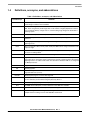
1.4
Definitions, acronyms, and abbreviations
Table 1. Definitions, acronyms, and abbreviations
Term/Acronym
Definition
BD file
Boot descriptor file, an input file to Elftosb that describes the flow of boot and different binary
and elf images included in the final SB file.
Bootlet
A bootlet is an image that can be executed on i.MX28 processor using ROM command CALL
HAB. These are generally small images that can be used to configure peripherals on board
such as external memory, voltage rails, etc., before loading larger images like bootloader or
operating system.
CA
Certificate Authority, the holder of a private key used to certify public keys.
CSF
Command Sequence File, a binary data structure interpreted by HAB to guide authentication
operations.
CST
Code Signing Tool, an application running on a host to generate a binary CSF and associated
digital signatures.
DCD
Device Configuration Data, a binary table used by the ROM code to configure the device at the
early boot stage.
DCP
Data Co-Processor, a cryptographic accelerator (including hash acceleration) found on some
processors including i.MX28.
Elftosb
Freescale tool available for Windows and Linux to generate i.MX28 boot images.
HAB
High Assurance Boot, a software library executed in internal ROM on the Freescale processor
at boot time which, among other things, authenticates software in external memory by verifying
digital signatures in accordance with a CSF. This document is limited to HAB v4, as configured
on i.MX28 processors.
IVT
Image Vector Table.
OS
Operating System.
OTP
PKCS#1
One-Time Programmable. OTP hardware includes masked ROM and electrically
programmable fuses (e-fuses).
Standard specifying the use of the RSA algorithm.
PKI
Public Key Infrastructure, a hierarchy of public key certificates in which each certificate (except
the root certificate) can be verified using the public key above it.
RSA
Public key cryptography algorithm developed by Rivest, Shamir and Adleman.
RVT
The ROM Vector Table (RVT) contains addresses of the HAB APIs available.
SA
SB file
Signature Authority, the holder of a private key used to sign software components.
A bootable image on i.MX28. It is generated using Elftosb tool and consists of header and
multiple sections including a section with ROM Boot Commands.
Secure Boot with i.MX28 HAB Version 4, Rev. 1
Freescale Semiconductor
3
i.MX28 security architecture overview
Table 1. Definitions, acronyms, and abbreviations (continued)
1.5
Term/Acronym
Definition
SRK
Super Root Key, an RSA key pair which forms the start of the boot-time authentication chain.
The SRK private keys are held by the CA. Unless explicitly noted, SRK in this document refers
to the public key only.
SRK Table
Super Root Key Table, HAB v4 uses an SRK Table with maximum length of up to four (4) keys,
allowing selection of the SRK used for a particular image. The hash of the SRK Table is
embedded in the processor using OTP hardware.
References
The references listed below are available for download at freescale.com using the keyword provided.
• i.MX28 Applications Processor Reference Manual. Keyword: MCIMX28RM.
• HAB Code-Signing Tool User’s Guide available in the Code Signing Tool package. Keyword:
IMX_CST_TOOL.
• Fuse programming guides, Programming OTP Bits and OTP Burner Documentation, are available
in the OTP tools package. Keyword: IMX_OTP_TOOLS.
• Elftosb documentation is available in the ELFTOSB package. Keyword: IMX_ELFTOSB_TOOL.
• High Assurance Boot Version 4 Application Programming Interface Reference Manual in the Code
Signing Tool package (version 2.0 and later). Keyword: IMX_CST_TOOL.
2
i.MX28 security architecture overview
This section gives a technical overview of the i.MX28 security architecture, providing the background
information needed for understanding the use cases and processes described in later sections.
2.1
ROM bootstrap code and HAB library
To design a correctly signed boot image, it is necessary to understand both the components which make
up HAB and the basic boot-time authentication process. This section gives an architectural level overview
of these elements which should be sufficient for most purposes.
The ROM bootstrap code is the first software executed after reset, and controls the initial phase of the boot
process, using the HAB library. HAB is used to authenticate the boot image in external memory prior to
its execution.
Based on pin or fuse settings, the ROM Bootstrap executes different boot modes to locate, load and execute
the boot image from various boot peripherals (for example, NAND flash, SD/MMC card, serial
EEPROM/flash, and USB recovery mode).
To ensure a secure boot, correct execution of the ROM Bootstrap must be guaranteed. To this end, its
integrity is protected by virtue of its location in masked processor-internal ROM. Execution of the Boot
ROM is also protected through disabling of external boot modes and interrupts.
Secure Boot with i.MX28 HAB Version 4, Rev. 1
4
Freescale Semiconductor
i.MX28 security architecture overview
The HAB library, embedded in the processor ROM, contains functions to authenticate an image as well as
initialize and test security hardware. The same library functions can be called from later boot stages to
extend the boot chain past the stage immediately after the Boot ROM.
The areas of an image that HAB verifies are completely customizable through a series of commands that
are interpreted by HAB. These are known as Command Sequence File (CSF) commands that define the
memory locations a digital signature covers, which keys to verify the signature with, and so on. All CSF
processing is done within the HAB library, including cryptographic hash and digital signature verification.
When appropriate, the HAB library makes use of the on-board hardware hash accelerator DCP to improve
boot performance. On i.MX28, HAB v4 uses the RSA algorithm with all signatures following the CMS
format, and all certificates following the X509v3 format.
For further details, see the i.MX28 Reference Manual in addition to the HAB CST User Guide listed in
Section 1.5, “References.”
NOTE
RSA public key sizes used for secure boot with HAB on i.MX28 are limited
to 1024 and 2048 bits only.
2.2
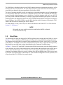
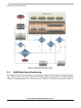
Boot flow
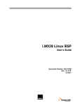
The Boot ROM execution state diagram for i.MX28 application processor that includes HAB v4 is shown
in Figure 1. The boot ROM for i.MX28 begins by loading a boot image (SB file) from bootable media.
The bootable section of the SB file consists of boot commands such as LOAD, LOAD DCD, CALL HAB,
JUMP HAB, etc. The ROM executes these commands in the sequence they are placed in the image binary.
More details are provided in the sections describing the tools to generate a bootable image.
In Figure 1, “Process CSF with HAB” is the point in the ROM execution state where the digital signatures
across an image are verified. When configured for secure operation, the Boot ROM on an i.MX28 device
will not allow unauthenticated code to execute and access to registers is limited for the LOAD DCD
command. Any signature failures or security violations force the boot ROM to enter USB recovery mode
to provision a new signed image to the boot device. Note that when configured for secure operation, even
images downloaded via USB must be properly signed.
Secure Boot with i.MX28 HAB Version 4, Rev. 1
Freescale Semiconductor
5
i.MX28 security architecture overview
Figure 1. Secure boot flow from device
2.3
HAB Public Key Infrastructure
HAB authentication is based on public key cryptography using the RSA algorithm in which image data is
signed offline using a series of private keys. The resulting signed image data then is verified on i.MX28
using the corresponding public keys. This key structure is known as a Public Key Infrastructure (PKI) tree.
Secure Boot with i.MX28 HAB Version 4, Rev. 1
6
Freescale Semiconductor
i.MX28 security architecture overview
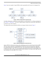
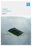
Figure 2 gives an example of a typical PKI tree that is generated by the Freescale Code Signing Tools.
Figure 2. HAB v4 enabled devices typical PKI tree
For further information on the PKI tree used for HAB v4, see the HAB CST User Guide as mentioned in
the Section 1.5, “References.” The details of digital signature authentication with the RSA algorithm are
beyond the scope of this document.
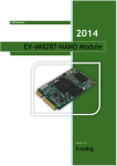
The authentication steps performed by HAB occur in stages which are shown in Figure 3.
Figure 3. HAB v4 dnabled devices detailed PKI tree
On the i.MX28, the authentication begins with establishing a root of trust with the Super Root Key (SRK).
HAB does this by computing a cryptographic hash of the SRK Table and comparing the result with a
pre-computed hash that is provisioned in OTP efuses. This ensures that the integrity of the SRK Table
included in the image is intact. This is the beginning of the authentication chain in which the SRK is used
to authenticate other keys which exist in the form of X509 certificates. For details on the SRK Table and
how to generate it, see the HAB CST User’s Guide.
Secure Boot with i.MX28 HAB Version 4, Rev. 1
Freescale Semiconductor
7
Designing for code signing
The arrows in Figure 3 show the authentication flow. For example, the SRK is used to authenticate both
the CSF key certificate and the image key certificates.
There are several important features to note. First, each key can certify multiple instances of the objects
beneath it. For example, a single SRK can certify multiple CSF keys, a single CSF key can authenticate
multiple CSFs (for example, on different product revisions), and a single image key can certify multiple
images. Nevertheless, the CSF key can only authenticate the CSF headers and commands. The objects
closer to the root of the PKI have greater impact if compromised, and require more protection. To some
extent, this is offered by the CST tool, but it is important that the CST user adopt appropriate policies and
processes. For example, a poorly planned CSF can open the way for malicious applications to be loaded
in place of the authentic one. It is therefore prudent to plan the CSF so it does not need to change with
every new version of the application, and restrict the group authorized to sign CSFs to a relatively small
number of people.
Second, the authentication of an image key through the CSF may be a little different to the other links
shown in Figure 3. In order to provide better key separation, an image key may be bound to the CSF using
a hash fingerprint embedded in the CSF. This means that it would not be possible to use the CSF with other
image keys, even if they have been certified by the same SRK. The addition of the hash is optional and is
dependent on whether the Hash Algorithm argument is present in the Install Key command. See the Install
Key command documentation in the HAB CST User’s Guide for further details.
Thirdly, each key type can authenticate only one data type. The SRK can authenticate only key certificates,
not CSFs or images. A CSF key can authenticate only CSFs. An image key can authenticate only images.
3
3.1
Designing for code signing
What components are required?
A secure boot requires a number of data components to be added to an image. This includes certificates,
signatures, Device configuration data (DCD) and CSF data.
NOTE
Although the i.MX28 ROM supports the use of DCD configuration of the
chip, it is optional. On the i.MX28, device configuration is typically
performed using bootlets using the Call command supported by the ROM.
See section 3.1.2 for further information on DCD.
When performing a secure boot on the i.MX28, Boot ROM and HAB require the following data
components to be defined in the image:
• Image Vector Table—A table of pointers used by the Boot ROM to locate other required data
components.
• CSF data—A block of data containing the commands that HAB will execute during boot.
• Certificates and associated signatures HAB uses to verify an image.
In addition to the above components, the location of the ROM Vector Table (RVT) is also required. The
RVT is a table of addresses defining the location of each of the HAB API functions. This is required as the
HAB library will be called to authenticate the next component in the boot chain. The structure of the RVT
Secure Boot with i.MX28 HAB Version 4, Rev. 1
8
Freescale Semiconductor
Designing for code signing
is defined in the High Assurance Boot Version 4 Application Programming Interface Reference Manual
included in the Freescale Code Signing Tool release package. The memory location of the RVT differs for
each member of the family. In this case, the location of the RVT for MX28 is documented in the i.MX28
Applications Processor Reference Manual.
3.1.1
Image Vector Table
The Image Vector Table (IVT) is a mandatory part of the boot image, and its structure is defined as:
typedef struct
{
uint32_t
header;
uint32_t
*entry;
uint32_t
reserved1;
uint32_t
*dcd;
boot_data_t
*boot_data;
uint32_t
*self;
uint32_t
*csf;
uint32_t
reserved2;
} hab_ivt_t;
Where:
uint32_t:
Header:
*entry:
reserved1:
*dcd:
*boot_data:
*self:
*csf:
reserved2:
A type representing a 32 bit unsigned integer.
Header identifying the type of data structure (0xD1), its size (0x0020), and HAB
version (0x40). For i.MX28, this is D100 2040h.
Absolute address of the first instruction to execute from the image.
Reserved and should be zero.
Absolute address of the image Device Configuration Table (DCD). If using
bootlets to configure i.MX28, this field should be set to NULL.
Absolute address of the Boot Data structure. This should be set to NULL for
i.MX28.
Absolute address of the IVT. Used internally by the ROM.
Absolute address of the Command Sequence File (CSF) used by the HAB library.
This field must be set to NULL when not performing a secure boot.
Reserved and should be zero.
The IVT is a block of data that must reside on the boot device. Every image including bootlets in the boot
sequence needs an IVT for ROM to run authentication process. Systems can be designed to have a single
IVT serving all the images in the boot sequence or have multiple IVTs one per image. This app note
provides examples of multiple IVTs, one per image. See Section 3.3, “How to assemble the HAB data with
Secure Boot with i.MX28 HAB Version 4, Rev. 1
Freescale Semiconductor
9
Designing for code signing
the boot image,” which discusses how the IVT is used in the signed image. Also see the i.MX28
Applications Processor Reference Manual for more detailed description of IVT data structure.
NOTE
The i.MX28 ROM requires that the IVT is followed by an unsigned 32-bit
integer in memory containing the size of entire image including IVT and
CSF data. See Boot Modes chapter of the i.MX28 Reference Manual for
more details.
3.1.2
Device Configuration Data
The main purpose of the DCD is to allow peripherals to be configured for optimal performance during
image authentication. A second purpose is to allow memory controllers to be configured in advance of
loading the image from non-volatile storage to its run-time location in external RAM. Since DCD
processing occurs prior to authentication, the scope of valid DCD operations is strictly limited to certain
controllers (clock, memories, etc.). The DCD is executed using the “LOAD DCD” ROM command and is
optional. For i.MX28 a bootlet, an independent image that resides in final boot image that is executed with
a “CALL HAB” ROM command, can also be used to initialize external memories. If using bootlets to
configure i.MX28, the use of DCD is not required.
For further details, see the Boot Modes chapter of the i.MX28 Reference Manual.
3.1.3
Command Sequence File
The CSF is a binary data structure interpreted by the HAB library to guide the authentication process. This
CSF binary structure is created using the HAB Code Signing Tool. The CSF contains commands which
determine:
• The PKI tree to be used in authentication operations.
• The physical memory regions to be authenticated, along with the authentication method and
reference data.
• Device configuration operations.
Device configuration operations in the CSF are similar to those in the DCD. The important difference
between the two is that DCD may configure only a limited range of peripherals (since DCD processing is
performed prior to authentication) whereas device configuration commands within the CSF are
unconstrained, because CSF commands are authenticated before they are executed.
With HAB, multiple non-contiguous regions of physical memory can be covered with a single digital
signature. The maximum number of regions is limited by the hash computation engine used, which may
also depend on the size and alignment of the images, as follows:
• When using DCP for the hash computation of digital signature verification a maximum of six (6)
non-contiguous blocks are supported.
• When using DCP all blocks except the final one must be multiples of 64 bytes in length (the final
data block may be an arbitrary length).
• When using the software implementation for hash computations included in HAB a maximum of
16 non-contiguous blocks are supported.
Secure Boot with i.MX28 HAB Version 4, Rev. 1
10
Freescale Semiconductor
Designing for code signing
3.1.4
Image layout
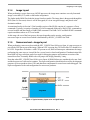
When performing a secure boot on an i.MX28 processor, the image must contain a correctly formatted
image vector table (IVT) with a valid header and pointers.
The loader inside ROM first loads the image from boot media. The image data is then passed through the
DCP (Data Co-Processor) where it will be decrypted (if it is an encrypted image) and placed at the
destination address.
As mentioned earlier in Section 2.2 the bootable section of the SB file consists of a sequence of boot
commands. Typically it consists of number of LOAD commands followed by HAB CALL commands to
execute bootlets and then finally a HAB JUMP command. The HAB CALL and HAB JUMP commands
require an address where an IVT was loaded.
At this stage, the rest of the boot process diverges depending on the security configuration:
non-secure/open or secure/closed which is determined by the SEC_CONFIG fuse field.
3.1.5
Nonsecure boot—image layout
When performing a non-secure boot with the SEC_CONFIG fuse field set to Open, it is not necessary to
provide the CSF data as part of the image. When no CSF is present, the CSF field of the IVT should be set
to NULL. Regardless of whether a valid CSF present or not, HAB will attempt to authenticate the image
performing the same steps as it would do for a secure boot in closed configuration. If authentication fails
then HAB will log events that can be later used for debugging purpose and continue execution of the
normal boot flow. Eventually ROM code will jump to the image pointed by *entry.
Note that when SEC_CONFIG fuse field is set to Open, all HAB failures are considered to be non- fatal
and the boot process is allowed to continue. The Open configuration should also be used for development
purposes of secure products where CSFs and other data components for secure boot can be debugged. The
Open configuration is the end configuration for non-secure products.
Figure 4. Typical memory layout of an unsigned image
Secure Boot with i.MX28 HAB Version 4, Rev. 1
Freescale Semiconductor
11
Designing for code signing
The IVT can appear anywhere before, in between or after the Image Data but not at address 0. Otherwise
*self in IVT points to NULL and is interpreted by HAB library as an invalid address.
The Image Length field as mentioned earlier must immediately follow the IVT and is the length of entire
image data including IVT and CSF data.
3.1.6
Secure boot—image layout
The SEC_CONFIG fuse field tells HAB whether the device is to boot securely or not. By setting this field
to Closed, the i.MX28 only allows a properly signed image to execute. In the Closed configuration the CSF
data component is mandatory and must be included in the image along with valid pointers in the IVT
structure. This is true regardless of which boot device is chosen, including USB recovery mode.
The first step performed by HAB when performing a secure boot is the installation of the SRK. It is
important to have the SRK tied to the processor to avoid replacement with an untrusted key. Therefore,
during the installation of the SRK, the ROM computes a SHA-256 hash of the SRK Table attached to the
binary CSF data. The result is compared to the reference value provisioned into the OTP fuses during
product manufacturing.
Next are the principal steps (not necessarily in order) involved in processing the CSF:
• Verify the CSF key certificate using the SRK.
• Verify the CSF signature using the CSF key.
• Verify image key certificates using the SRK.
• Verify image signature(s) using the image keys.
• Perform any device configuration operations specified in the CSF.
Note that not all steps apply to every CSF.
If HAB authentication is successful, ROM code jumps into the image code pointed to *entry.
Secure Boot with i.MX28 HAB Version 4, Rev. 1
12
Freescale Semiconductor
Designing for code signing
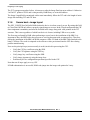
Figure 5. Typical memory layout of a signed image
The IVT can appear anywhere before, in between, or after Image Data but not at address 0. Otherwise *self
in IVT points to NULL and that will be interpreted by HAB library as an invalid address. Also the CSF
and associated data (SRK Table, Signatures and Certificates) need not be concatenated together but it is
the default output of the CST.
The Size field must immediately follow the IVT and it is the length of entire image data including IVT and
CSF data. See the Boot Modes chapter of the reference manual for more details.
NOTE
HAB requires that the IVT, the Size field and at minimum, the first word of
the Image Data all must be covered by a digital signature. Failure to do so
will result in HAB issuing an assertion audit log event and the ROM
refusing to launch the image.
3.2
3.2.1
Generating the HAB data
Generating the Command Sequence File data (CSF)
The CSF contains all the commands that HAB will execute during the secure boot. These commands
instruct HAB on which memory areas of the image to authenticate, which keys to install, which keys to
use for signature verification, what data to write to a particular register, and so on.
Every image including bootlets in the boot sequence must be signed. There could be a single CSF for all
the images in the boot sequence or multiple CSFs, one for each image. A single CSF is possible if images
do not overlap in memory but the examples presented in this app note use multiple CSFs as they occupy
same space in memory.
Secure Boot with i.MX28 HAB Version 4, Rev. 1
Freescale Semiconductor
13
Designing for code signing
The first CSF in the boot sequence must contain an Install SRK command to install a single SRK from the
SRK Table provided. Also, it must contain an Install CSFK command to install the CSF key prior to CSF
authentication. Subsequent CSFs in the boot sequence do not require Install SRK and Install CSFK
commands. Every CSF must contain an Authenticate CSF command to authenticate the CSF contents
using the CSF key.
To facilitate well-formed CSF generation, Freescale provides a reference Code Signing Tool
(IMX_CST_TOOL) for the creation of the CSF data necessary to perform a secure boot. The CST release
package is available at freescale.com as shown in the list of references.
The binary output from the CST consists of the following components:
• CSF commands interpreted by HAB
• SRK Table and corresponding fuse pattern
• Public key certificates
• CSF Signature
• One or more Image signatures
NOTE
Prior to continuing with examples described below see the CST User’s
Guide available in the above mentioned package to obtain a better
understanding of the code signing process and how to use the CST.
3.2.2
Generating keys and the Super Root Key (SRK) Table
To begin, HAB code signing keys are required. The CST provides scripts to generate the required private
keys and public key certificates. In addition to the keys a SRK table must also be generated.
The following steps illustrate how the keys and SRK Table can be generated:
1. Generating HAB code signing keys—To generate the standard code signing keys for HAB run the
following command:
./hab4_pki_tree.sh
The resulting private keys will be placed in the keys directory of the CST and the corresponding
X.509 certificates will be placed in the crts directory. The private keys are stored in password
protected files in PKCS#8 format but care must be taken to ensure that the confidentiality of these
keys is maintained.
For details on key generation with the CST, see HAB CST User Guide.
2. Generating an SRK Table—The SRK Table is constructed from up to four public SRKs. A
cryptographic hash of this table is generated by the CST for provisioning to the SRK_HASH field
in OTP fuses during manufacturing. At boot time an Install SRK CSF command specifies the
location of the SRK Table in memory as well as the index of the SRK to use for authenticating the
remaining keys.
To generate an SRK Table the CST provides the srktool, which requires X.509v3 public key
certificates for the SRKs as inputs. The following is an example to generate an SRK Table with
four keys:
Secure Boot with i.MX28 HAB Version 4, Rev. 1
14
Freescale Semiconductor
Designing for code signing
../linux/srktool –h 4 –t SRK_1_2_3_4_table.bin –e SRK_1_2_3_4_fuse.bin –d sha256 –c
./SRK1_sha256_2048_65537_v3_ca_crt.pem,./SRK2_sha256_2048_65537_v3_ca_crt.pem,./SRK3_sh
a256_2048_65537_v3_ca_crt.pem,./ SRK4_sha256_2048_65537_v3_ca_crt.pem –f 1
For details on key generation with the CST, see HAB CST User Guide.
NOTE
Section 6, “Manage the electrical fuses,” provides guidance on how to blow
fuses, and which fuses must be blown for a secure product.
3.2.3
Generating the binary CSF and signatures
The HAB CST User Guide (listed in Section 1.5, “References”) explains in detail how to use CSF input
file with CST tool to generate CSF binary data and signatures. Refer to Section 4 of the HAB CST User
Guide (HABCST_UG_Rev_1.pdf) available in the Code Signing Tool package, downloadable on the
website freescale.com.
3.3
How to assemble the HAB data with the boot image
This section lists out typical code changes needed to accommodate HAB data (including the binary CSF,
certificates and signatures) and the IVT data structure. The purpose is to create a boot image that is
organized as represented by Figure 5.
The following definitions will be referred to in the steps below:
• __hab_data: symbol name for the start of HAB data in memory
• input_ivt: symbol name for start of IVT data in memory
1. The first step is to modify the linker file to preserve space and a symbol name “__hab_data” for
HAB data. Also make sure input_ivt and CSF are not located at address 0. Below are the
typical linker file changes in bold italic, with the __hab_data symbol name and reserving
0x2000 bytes for *csf.
OUTPUT_ARCH(arm)
ENTRY(_start)
SECTIONS
{
/* Image loaded at address 0x10 to avoid input_ivt at 0 */
. = 0x00000010;
. = ALIGN(4);
. = BASE_ADDR;
.text : { *(.text) }
.rodata : { *(.rodata) }
.data : { *(.data) }
/* Allow the section for future growth with padding
to a known length */
. = BASE_ADDR + 0x2A000;
Secure Boot with i.MX28 HAB Version 4, Rev. 1
Freescale Semiconductor
15
Designing for code signing
/* reserve this area to store HAB related data such as
* CSF commands, certificates and signatures
*/
__hab_data = .;
. = . + 0x2000;
__hab_data_end = .;
/* place the __hab_data memory region before the .bss
* region to avoid being over written at runtime and to
* keep the u-boot binary as small as possible
*/
. = ALIGN(4);
.bss
: { *(.bss) }
}
2. The next step is to add the IVT data structure, image length and symbol name input_ivt to
locate the IVT data structure in memory. Following is a typical implementation of input_ivt
that includes IVT data structure and followed by the “Image Length” field containing the length
of the entire image including HAB data. Note the use of symbol __hab_data in initialization of
*csf pointer in IVT and the use of __hab_data_end and BASE_ADDR in calculating the
length of the image.
#include <hab.h>
/* hab_ivt_t is defined in hab.h */
struct _hab_aut {
hab_ivt_t ivt;
uint32_t img_len;
};
const struct _hab_aut input_ivt __attribute__((section(".data"),aligned(4))) = {
{
// hdr word with tag #HAB_TAG_IVT, length and HAB version fields
IVT_HDR(sizeof(struct hab_ivt), HAB_VER(4, 0)),
// Absolute address of the first instruction to execute
(hab_image_entry_f) (&_start),
// Reserved in this version of HAB: should be NULL
NULL,
// Absolute address of the image DCD: may be NULL
NULL,
Secure Boot with i.MX28 HAB Version 4, Rev. 1
16
Freescale Semiconductor
Signed U-Boot and Linux kernel example
// Absolute address of the Boot Data: may be NULL, but not
// interpreted any further by HAB
NULL,
// Absolute address of the IVT
(const void*) (&input_ivt),
// Absolute address of the image CSF (CSF data generated by cst)
(const void*) (&__hab_data),
// Reserved in this version of HAB: should be zero.
0
},
// image length including CSF data calculated from linker symbol __hab_data_end
// and BASE_ADDR, defined in Makefile and used at compile time
(const void*) (&__hab_data_end) – BASE_ADDR;
};
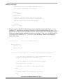
3. Finally changes are required to the boot descriptor file (.bd or BD file) for use with Elftosb to
generate a final bootable image with HAB data. For sample u-boot BD and Linux kernel BD files,
refer to Section 4.1, “Sample boot descriptor file used for u-boot Image,” and Section 4.2,
“Sample boot descriptor file used for Linux kernel image.”
4
Signed U-Boot and Linux kernel example
U-Boot is a bootloader commonly used to boot a Linux device and is provided in the Freescale Linux BSP.
i.MX28 specific U-Boot consists of three ELF files:
• power_prep
• boot_prep
• u-boot
Power_prep and Boot_prep are bootlet images that are used to prepare the board and initialize the external
memory before loading the u-boot image. Bootlets are also part of Linux BSP with imx-bootlets-src
package. For secure boot we need to generate HAB data for all three ELF files. The streaming boot
architecture of i.MX28 enables all three signed images with HAB data to reside in the same SB file. The
boot descriptor file described in Section 4.1, “Sample boot descriptor file used for u-boot Image,” dictates
the sequence of boot commands in the bootable section of u-boot SB file.
Similarly the Linux kernel of i.MX28 consists of power_prep, boot_prep, linux_prep and zImage boot
components and the sequence of boot commands in the bootable section of Linux SB file is shown in
Section 4.2, “Sample boot descriptor file used for Linux kernel image.”
Secure Boot with i.MX28 HAB Version 4, Rev. 1
Freescale Semiconductor
17
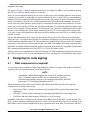
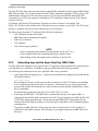
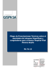
Signed U-Boot and Linux kernel example
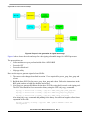
Figure 6. Players in the generation of signed boot image
Figure 6 above shows the tools and steps for code signing a bootable image for i.MX28 processor.
The prerequisites are:
• Linux machine set up to perform builds of the i.MX28 BSP
• Freescale CST
• Freescale elftosb tool
• Objcopy utility
Here are the steps to generate signed u-boot SB file:
1. The source code changes described in section 3.3 are required for power_prep, boot_prep and
u-boot.
2. Build the three ELF files for power_prep, boot_prep and u-boot. Follow the instructions in the
BSP guide on how to build imx-bootlets and u-boot.
3. Next step is to generate HAB data for the three ELF files using the Freescale code signing tool.
The ELF files should be first converted to binary using the GNU objcopy command.
objcopy -I elf32-little -O binary –-gap-fill 0xFF power_prep power_prep.bin
objcopy -I elf32-little -O binary –-gap-fill 0xFF boot_prep boot_prep.bin
objcopy -I elf32-little -O binary -–gap-fill 0xFF u-boot u-boot.bin
Also using objcopy command add padding to the binary for sufficient length to allow future
expansion of the code
objcopy -I binary -O binary –-gap-fill 0xFF –-pad-to 0x2A000 u-boot.bin
u-boot_pad.bin
Secure Boot with i.MX28 HAB Version 4, Rev. 1
18
Freescale Semiconductor
Signed U-Boot and Linux kernel example
The HAB data is generated using the code signing tool. Section 8, “Example CSF text files for
reference,” illustrates sample CSF files including u-boot.csf and boot_prep.csf.
cst –o boot_prep_hab_data < boot_prep.csf
cst –o power_prep_hab_data < power_prep.csf
cst –o uboot_hab_data < u-boot.csf
4. Finally the elftosb tool is used to generate the signed SB file. Elftosb is described in
Section 5.2, “IMX_ELFTOSB_TOOL.”
./elftosb -z -V -f imx28 -c ./uboot_ivt.bd –o imx28_ivt_uboot.sb
Here are the steps to generate a signed Linux kernel SB file.
1. The source code changes described in section 3.3 are required for all three bootlets: power_prep,
boot_prep and linux_prep.
2. Build the three ELF files for power_prep, boot_prep and linux_prep. Follow the instructions in
the BSP guide to build the three bootlets.
3. Next step is to generate HAB data for the Linux kernel binary file (zImage) and the 3 bootlets
using the Freescale code signing tool. The ELF files should be first converted to binary using the
GNU objcopy command.
objcopy -I elf32-little -O binary –gap-fill 0xFF power_prep power_prep.bin
objcopy -I elf32-little -O binary –gap-fill 0xFF boot_prep boot_prep.bin
objcopy -I elf32-little -O binary –gap-fill 0xFF linux_prep linux_prep.bin
The BSP design of linux_prep is a little complex in that it is executed twice. The first instance it is
executed using the CALL HAB command and second instance using the JUMP HAB command.
The execution flow can better be understood using Section 4.2, “Sample boot descriptor file used
for Linux kernel image.” The first execution modifies the memory at byte offset 0x24 to 1. If we
want to authenticate the entire linux_prep for both executions then we will have to generate two
signatures. The first signature will be used with CALL HAB with offset 0x24 showing original
value ‘0’ and second signature used for authenticating linux_prep with JUMP HAB showing a
value of 1 at offset 0x24. We do this by first copying linux_prep, bin to linux_kernel.bin, then
manually modify byte 0x24 to 1 using a hex editor and include linux_kernel.bin in linux_kernel.csf
for signature generation.
cp linux_prep.bin linux_kernel.bin
using a hex editor set byte 0x24 to 1
The HAB data is generated using the code signing tool. Section 8, “Example CSF text files for
reference,” illustrates sample CSF files including linux_prep.csf and linux_kernel.csf.
cst –o boot_prep_hab_data < boot_prep.csf
cst –o power_prep_hab_data < power_prep.csf
cst –o linux_prep_hab_data < linux_prep.csf
cst –o linux_kernel_hab_data < linux_kernel.csf
4. Finally the elftosb tool is used to generate the signed SB file. Elftosb is described in
Section 5.2, “IMX_ELFTOSB_TOOL.”
./elftosb -z -V -f imx28 -c ./linux_ivt.bd –o imx28_ivt_linux.sb
Secure Boot with i.MX28 HAB Version 4, Rev. 1
Freescale Semiconductor
19
Signed U-Boot and Linux kernel example
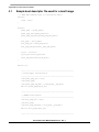
4.1
Sample boot descriptor file used for u-boot Image
// i.MX28 ROM command script to load and run U-Boot
options {
flags = 0x01;
}
sources {
power_prep = "power_prep";
power_prep_bin="power_prep.bin";
power_prep_hab_data="power_prep_hab_data";
boot_prep = "boot_prep";
boot_prep_bin ="boot_prep.bin";
boot_prep_hab_data="boot_prep_hab_data";
u_boot = "u-boot";
u_boot_bin="u-boot_pad.bin";
uboot_hab_data="uboot_hab_data";
}
section (0) {
//---------------------------------------------------------// Power Supply initialization
//---------------------------------------------------------load power_prep_bin > 0x10;
load power_prep;
load power_prep_hab_data > power_prep:__hab_data;
hab call power_prep:input_ivt;
//---------------------------------------------------------// SDRAM initialization
//---------------------------------------------------------load boot_prep_bin > 0x10;
load boot_prep;
load boot_prep_hab_data > boot_prep:__hab_data;
hab call boot_prep:input_ivt;
//----------------------------------------------------------
Secure Boot with i.MX28 HAB Version 4, Rev. 1
20
Freescale Semiconductor
Signed U-Boot and Linux kernel example
// Load and call u_boot - ELF ARM image
//---------------------------------------------------------load u_boot_bin > 0x41008000;
load u_boot;
load uboot_hab_data > u_boot:__hab_data;
hab jump u_boot:input_ivt;
}
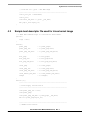
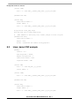
4.2
Sample boot descriptor file used for Linux kernel image
// i.MX28 ROM command script to load and run Linux kernel
options {
flags = 0x01;
}
sources {
power_prep
= "./power_prep";
power_prep_bin
= "./power_prep.bin";
power_prep_hab_data
= "./power_prep_hab_data";
boot_prep
= "./boot_prep";
boot_prep_bin
= "./boot_prep.bin";
boot_prep_hab_data
= "./boot_prep_hab_data";
linux_prep
= "./linux_prep";
linux_prep_bin
= "./linux_prep.bin";
linux_prep_hab_data
= "./linux_prep_hab_data";
linux_kernel_hab_data
= "./linux_kernel_hab_data";
zImage
= "./zImage";
}
section (0) {
//---------------------------------------------------------// Power Supply initialization
//---------------------------------------------------------load power_prep_bin > 0x10;
load power_prep;
load power_prep_hab_data > power_prep:__hab_data;
hab call power_prep:input_ivt;
//---------------------------------------------------------// SDRAM initialization
Secure Boot with i.MX28 HAB Version 4, Rev. 1
Freescale Semiconductor
21
Encrypted boot and Elftosb
//---------------------------------------------------------load boot_prep_bin > 0x10;
load boot_prep;
load boot_prep_hab_data > boot_prep:__hab_data;
hab call boot_prep:input_ivt;
//---------------------------------------------------------// Prepare to boot Linux
//---------------------------------------------------------load linux_prep_bin > 0x2000;
load linux_prep;
load linux_prep_hab_data > linux_prep:__hab_data;
hab call linux_prep:input_ivt;
//---------------------------------------------------------//
Load and start Linux kernel
//---------------------------------------------------------load zImage > 0x40008000;
load linux_kernel_hab_data > linux_prep:__hab_data;
hab jump linux_prep:input_ivt;
}
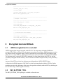
5
5.1
Encrypted boot and Elftosb
i.MX28 encrypted boot in a nut-shell
i.MX28 supports boot images encrypted with AES-128. The entire image including HAB data is
encrypted. The Elftosb tool from Freescale supports encryption of boot images. Elftosb generates a session
key which is used to encrypt the image. The user generates one or more input OTP keys using Keygen
utility. For every input OTP key, elftosb generates an entry in a key dictionary residing inside the SB file.
The dictionary entry consists of CBC-MAC computed over boot image header with OTP key and the
session key encrypted with the OTP key. There is no limit on number of input OTP keys or key dictionary
size.
Any one of the OTP keys in the key dictionary can be burned into i.MX28 CRYPTO fuses.
At boot time, the ROM computes a CBC-MAC over the boot image header with the OTP Key, finds a
matching entry in the key dictionary of the image, decrypts the session key with the OTP key and decrypts
the rest of the image with decrypted session key.
5.2
IMX_ELFTOSB_TOOL
The IMX_ELFTOSB_TOOL package is available on freescale.com.
Secure Boot with i.MX28 HAB Version 4, Rev. 1
22
Freescale Semiconductor
Manage the electrical fuses
The package contains executable elftosb.exe for Windows and elftosb for UNIX. See the documentation
available in the package for detailed explanation of elftosb and the image encryption and decryption
process
6
Manage the electrical fuses
6.1
Tools to blow the fuses
For programming any fuse on i.MX28, Freescale recommends using the IMX_OTP_TOOLS package
available on freescale.com, search for “IMX_OTP_TOOLS.”
The fuse programming package consists of a set of scripts, tools and relevant documentation to program
any fuse including the SRK hash and CRYPTO key fuses.
Using these tools will guarantee programming of fuses in correct byte order.
6.2
•
•
6.3
6.3.1
Documents available in the package
Programming_OTP_Bits.pdf: describes various tools available for programming OTP fuses on
i.MX28.
OTP_Burner_Documentation.pdf: describes the usage of otp_burner.py script.
List of tools available in the package
OTP_BURNER.PY
This is a python script to generate an otpinit.sb application that is downloaded on i.MX28 to program the
fuses. The otp_burner.py script can be run on either Windows or UNIX hosts. The inputs to the script are:
• fuses.bin file used with --srk option, fuses.bin file is the output of SRKTOOL available with CST
package. Fuses.bin contains the hash of SRK Table in binary format.
• encryption key with --key option, described in otp_burner_documentation.pdf
• input text file with --input option, described in otp_burner_documentation.pdf
See the documentation available with the IMX_OTP_TOOLS package for a detailed description on the
usage of Otp_Burner.py.
6.3.2
BITINIT.EXE
BitInit.exe is a Windows application used to download and execute the otpinit.sb file in the internal RAM
of i.MX28 when connected to PC host in USB recovery mode. The OtpInit.sb file is the output of
Otp_burner.py described above.
6.3.3
KEYGEN and KEYGEN.EXE
Keygen is used to create random encryption keys called as input OTP keys. These keys are programmed
into fuses using otp_burner.py and BitInit.exe tools.
Secure Boot with i.MX28 HAB Version 4, Rev. 1
Freescale Semiconductor
23
Manage the electrical fuses
On Windows (Keygen.exe), cryptographically secure RNG APIs in the OS are used to generate the random
key.
On Linux (Keygen), /dev/random is used to generate the random key.
6.4
Recommendations on i.MX28 fuse configuration
During production, it is suggested to change the SEC_CONFIG of the chip to Closed configuration only
once the programming, provisioning, validation and other pre-production steps are working successfully
in Open configuration. When only secure boot is allowed, every boot image whatever the boot mode is,
must be signed and authenticated correctly prior its execution so it is easier to fix any issues encountered
with a chip still in Open configuration.
Some important boot parameters are set through the fuses. The fact that a fuse is only One Time
Programmable is sufficient to prevent the change of a 1-bit parameter, but is not sufficient to prevent the
modification of a larger value such as the hash of the SRK Table. Therefore lock fuses are dedicated to
protect such information. It is recommended to blow these fuses once the value is programmed and verified
to be functional.
For instance, with the i.MX28, once the SRK_HASH[255:0] is programmed, the fuse SRK LOCK bit
must be programmed to disable any modification of the reference digest for the super toot key table.
For a description of the lock fuses, refer to Programming_OTP_Bits.pdf available with
[IMX_OTP_TOOLS] package, listed in Section 1.5, “References.”
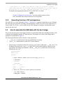
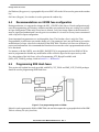
6.5
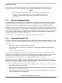
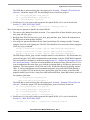
Programming SRK Hash fuses
This section will explain how tools provided with IMX_CST_TOOL and IMX_OTP_TOOLS packages
should be used to programming SRK Hash fuses.
Figure 7. Fuse programming tools on i.MX28
Srktool is used to generate the HAB v4 SRK Table; the tool also outputs the cryptographic hash of the SRK
Table in a binary file (srk_fuses.bin).
Secure Boot with i.MX28 HAB Version 4, Rev. 1
24
Freescale Semiconductor
Development and debug tips
The otp_burner.py script uses the binary SRK hash file to generate an executable image that can program
fuses. The output image otp_init.sb resulting from otp_burner.py is then downloaded to i.MX28 using
BitInit.exe. The i.MX28 must be connected in USB recovery mode in order for BitInit.exe to download
the SB file to internal RAM on the device. When executed on i.MX28 otp_init.sb programs the SRK fuses.
Using these tools will ensure SRK and other fuses are programmed correctly.
The arguments to otp_burner.py to generate otp_init.sb with SRK fuse programming is --srk:
otp_burner.py --srk srk_fuses.bin --key encryption_key.txt –i bit_settings.txt –o
otp_init.sb
The bit_settings.txt file provided with –i option carries values for other fuses. The format of bit_settings.txt
file is specified in the documentation with the IMX_OTP_TOOLS package.
The file encryption_key.txt is the 128 bit OTP key created using keygen utility. The 128 bit OTP key will
be programmed to the fuses that ROM uses in decrypting the boot image.
7
7.1
Development and debug tips
Error logging
In development phase it is always wise to test the device in Open configuration. It is recommended for
boot images to use ROM HAP API report_event to browse through the events created during HAB
authentication. The report_status API can be used to determine the security configuration and security
state of the system. Detailed information on HAB Event Data is available on request from Freescale
representative. All FAILURE events reported by HAB in Open configuration must be resolved before
moving on to Closed configuration, otherwise the image will not boot. Here is example code that can be
included in u-boot to print any events occurred during the image authentication process. This example
could be extended to report all warning events as well using HAB_STS_ANY instead of HAB_FAILURE
in hab_report_event. While they do not prevent booting in Closed configuration, warning events should
still be analyzed. For example, if software hash is used when DCP hash was requested, there is a warning,
not a failure. Given that it slows down the boot, it is a good idea to fix all warnings before final production
using the image.
int get_hab_status(void)
{
uint32_t index = 0; /* Loop index */
uint8_t event_data[128]; /* Event data buffer */
size_t bytes = sizeof(event_data); /* Event size in bytes */
hab_config_t config= 0;
hab_state_t state = 0;
/* Check HAB status */
if (hab_rvt_report_status(&config, &state) != HAB_SUCCESS)
{
printf("\nHAB Configuration: 0x%02x HAB State: 0x%02x\n",
config, state);
Secure Boot with i.MX28 HAB Version 4, Rev. 1
Freescale Semiconductor
25
Example CSF text files for reference
/* Display HAB Failure events */
while (hab_rvt_report_event(HAB_FAILURE, index, event_data, &bytes)
== HAB_SUCCESS)
{
printf("\n");
printf("---------HAB Event %d -----------------\n", index + 1);
printf("event data:\n");
/* display_event will simply prints out the contents of events_data */
display_event(event_data, bytes);
printf("\n");
bytes = sizeof(event_data);
index++;
}
/* Check reason for stopping */
if (hab_rvt_report_event(HAB_STS_ANY, index, NULL, &bytes)
== HAB_SUCCESS)
{
printf("ERROR: Recompile with larger event data buffer – at least %d
bytes\n",
bytes);
}
}
/* Display message if no HAB Failure events are found */
else
{
printf("\nHAB Configuration: 0x%02x HAB State: 0x%02x\n",
config, state);
printf("No HAB Failure Events Found!\n\n");
}
}
8
Example CSF text files for reference
This section provides sample input CSF files used for u-boot, linux_kernel and boot_prep code signing.
8.1
U-boot CSF example
[Header]
Version = 4.0
Hash Algorithm = sha256
Secure Boot with i.MX28 HAB Version 4, Rev. 1
26
Freescale Semiconductor
Example CSF text files for reference
Engine Configuration = 0
Certificate Format = X509
Signature Format = CMS
[Install SRK]
File = "../crts/srk_tbl1_2_3_4.bin"
# Specify the index of the SRK in the SRK Table
Source index = 0
[Install CSFK]
File = "../crts/CSF1_1_sha256_2048_65537_v3_usr_crt.pem"
[Authenticate CSF]
[Install Key]
Verification index = 0
Target index = 2
File = "../crts/IMG1_1_sha256_2048_65537_v3_usr_crt.pem"
# Sign entire u-boot image
# Blocks have the following definition:
#
Base address of the binary file, Offset of the block within the binary file,
Length of block in bytes, binary file name
[Authenticate Data]
Verification index = 2
Engine = DCP
Blocks = 0x41008000 0x0 0x2A000 "u-boot_pad.bin"
8.2
Linux_prep CSF example
[Header]
Version = 4.0
Hash Algorithm = sha256
Engine Configuration = 0
Certificate Format = X509
Signature Format = CMS
[Install SRK]
File = "../crts/srk_tbl1_2_3_4.bin"
Source index = 0
Secure Boot with i.MX28 HAB Version 4, Rev. 1
Freescale Semiconductor
27
Example CSF text files for reference
[Install CSFK]
File = "../crts/CSF1_1_sha256_2048_65537_v3_usr_crt.pem"
[Authenticate CSF]
[Install Key]
Verification index = 0
Target index = 2
File = "../crts/IMG1_1_sha256_2048_65537_v3_usr_crt.pem"
# Sign entire linux_prep image
# Blocks have the following definition:
#
Base address of the binary file, Offset, Length of block in bytes
[Authenticate Data]
Verification index = 2
Engine = DCP
Blocks = 0x00002000 0x0 0x4000 "linux_prep.bin”
8.3
Linux_kernel CSF example
[Header]
Version = 4.0
Hash Algorithm = sha256
Engine Configuration = 0
Certificate Format = X509
Signature Format = CMS
[Install SRK]
File = "../crts/srk_tbl1_2_3_4.bin"
Source index = 0
[Install CSFK]
File = "../crts/CSF1_1_sha256_2048_65537_v3_usr_crt.pem"
[Authenticate CSF]
[Install Key]
Verification index = 0
Target index = 2
File = "../crts/IMG1_1_sha256_2048_65537_v3_usr_crt.pem"
Secure Boot with i.MX28 HAB Version 4, Rev. 1
28
Freescale Semiconductor
Example CSF text files for reference
# Sign entire linux_prep image
# Sign entire zImage
# Blocks have the following definition:
#
Base address of the binary file, Offset, Length of block in bytes
[Authenticate Data]
Verification index = 2
Engine = DCP
Blocks = 0x00002000 0x0 0x4000 "linux_kernel.bin", \
0x40008000 0x0 0x2DA030 "zImage"
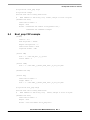
8.4
Boot_prep CSF example
[Header]
Version = 4.0
Hash Algorithm = sha256
Engine Configuration = 0
Certificate Format = X509
Signature Format = CMS
[Install SRK]
File = "../crts/srk_tbl1_2_3_4.bin"
Source index = 0
[Install CSFK]
File = "../crts/CSF1_1_sha256_2048_65537_v3_usr_crt.pem"
[Authenticate CSF]
[Install Key]
Verification index = 0
Target index = 2
File = "../crts/IMG1_1_sha256_2048_65537_v3_usr_crt.pem"
# Sign entire boot_prep image
# Blocks have the following definition:
#
Base address of the binary file,
Offset, Length of block in bytes
[Authenticate Data]
Verification index = 2
Engine = DCP
Blocks = 0x10 0x0 0x4000 "boot_prep.bin"\
Secure Boot with i.MX28 HAB Version 4, Rev. 1
Freescale Semiconductor
29
Revision history
9
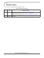
Revision history
Table 2 provides a revision history for this application note.
Table 2. Document revision history
Rev.
Number
Date
1
05/13
0
08/2012
Substantive Change(s)
•
•
•
•
Added RVT term and definition to Table 1,“Definitions, acronyms, and abbreviations.”
Added reference to i.MX28 Reference Manual in Section 1.5, “References.”
Added note about RSA public key sizes to Section 2.1, “ROM bootstrap code and HAB library.”
Added information regarding the RVT in Section 3.1, “What components are required?”
Initial release.
Secure Boot with i.MX28 HAB Version 4, Rev. 1
30
Freescale Semiconductor
How to Reach Us:
Information in this document is provided solely to enable system and software
Home Page:
freescale.com
implementers to use Freescale products. There are no express or implied copyright
Web Support:
freescale.com/support
information in this document.
licenses granted hereunder to design or fabricate any integrated circuits based on the
Freescale reserves the right to make changes without further notice to any products
herein. Freescale makes no warranty, representation, or guarantee regarding the
suitability of its products for any particular purpose, nor does Freescale assume any
liability arising out of the application or use of any product or circuit, and specifically
disclaims any and all liability, including without limitation consequential or incidental
damages. “Typical” parameters that may be provided in Freescale data sheets and/or
specifications can and do vary in different applications, and actual performance may
vary over time. All operating parameters, including “typicals,” must be validated for
each customer application by customer’s technical experts. Freescale does not convey
any license under its patent rights nor the rights of others. Freescale sells products
pursuant to standard terms and conditions of sale, which can be found at the following
address: freescale.com/SalesTermsandConditions.
Freescale and the Freescale logo are trademarks of Freescale Semiconductor, Inc.,
Reg. U.S. Pat. & Tm. Off. All other product or service names are the property of their
respective owners. ARM is the registered trademark of ARM Limited.
© 2012, 2013 Freescale Semiconductor, Inc.
Document Number: AN4555
Rev. 1
05/2013