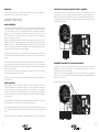
1
334im
335im
336im
PN# 319-1063 rev A
5/99
declaration of conformity
manufacturer’s name:
manufacturer’s address:
analog and digital systems, inc
300 wildwood avenue
woburn, ma 01801
usa
declares, that the product:
product name:
334im
335im
336im
conforms to the following standards:
EN 50 081-1/1992
EN 50 082-1/3.1995
european contact:
Axel Perlwitz
audiomax GmbH
Heilbronn Germany
2
19
table of contents
introduction........................................................................................ 3
about this manual..................................................................................3
features of your 3-series loudspeaker............................................................... 4
warnings and tips.................................................................................. 5
system planning.................................................................................... 5
amplifier requirements................................................................... 6
mounting locations................................................................................. 6
controls and connections........................................................................... 6
tweeter level control.................................................................... 6
midrange contour........................................................................ 7
connections to the amplifier............................................................ 7
speaker wiring..................................................................................... 7
speaker wire selection.................................................................. 7
polarity and phasing.................................................................... 7
t e r m i n a t i o n ........................................................................ 8
speaker mounting.................................................................................. 8
woofer installation....................................................................... 8
woofer mounting........................................................................ 8
tweeter installation...............................................................................10
angle direction.........................................................................10
crossover installation..............................................................................12
connecting the system................................................................ 12
connections to crossover network and radio or amplifier............................... 13
bi-amplified connections to the crossover network.................................. 13
bi-wired connections to the crossover network..................................... 14
troubleshooting................................................................................. 15
jack pinouts...................................................................................... 16
specifications.................................................................................... 16
warranty information............................................................................. 17
ce declaration of conformity..................................................................... 19
introduction
Thank you for choosing this a/d/s/ integrally mounted automotive loudspeaker. Your new
loudspeaker system is the latest innovation in reference quality automotive loudspeakers. Its
unique combination of high technology design and real-world convenience features make it the
ideal addition to any quality music system. a/d/s/ takes great pride in manufacturing products
that truly stand the test of time, from their renowned mini-speakers to whole house systems of
the grandest proportion. With a minimum of care, this a/d/s/ product will provide years of
trouble-free satisfaction. Keep this manual in a safe place, it’s likely you will use it again &
again!
about this manual
To get the most from your a/d/s/ 3-series loudspeaker, we recommend that you read this manual
thoroughly before using. If there is anything that you do not fully understand, please consult
with your a/d/s/ dealer before attempting the installation.
18
3
features of your 3-series loudspeaker
warranty information
molded woofer basket - the back bone of any good woofer is it’s basket. It provides the
proper alignment and support structure for the magnet while the very thin braces guarantee a
minimum of early reflections off the basket that would be ordinarily transmitted as sonic colorations
through the cone.
There are two things you must do to ensure trouble free service in the event you need warranty repairs.
1 - Keep your original sales receipt in a safe place. A copy of the receipt will be required to obtain warranty service.
2 - Be sure your retail dealer has written the date, the model number, and the serial number (if applicable) of the Product on the
receipt.
To give yourself an extra measure of protection, make a separate record of the information about your purchase and keep it in
a safe place. In the event you misplace the sales receipt, your dealer may be able to give you a copy.
Take a moment now to read the terms of your warranty. Check to be sure your sales receipt is dated and has the Product model
number and serial number (if applicable) on it. Then put it away in a safe place.
When shipping a Product in for service:
• Enclose a copy of your original sales receipt that has the date, the Product model number and serial number (if applicable)
written on it.
• Always ship Products in the complete original packing material.
• Avoid shipping Products via the Postal service. If you must use the Postal service, be sure to register and insure the package.
a/d/s/ Limited Warranty
Analog and Digital Systems, Inc. (a/d/s/) warrants to the original consumer purchaser of the a/d/s/ Products described in this
manual, that the Product will be free from defects in materials and workmanship for a period of one (1) year after the date of
purchase. If the product is installed by an authorized a/d/s/ retail dealer, the warranty is extended to three (3) years, a/d/s/' sole
obligation under this warranty shall be to provide, without charge, parts and labor necessary to remedy the defects, if any, that
appear during the warranty period.
tweeter level control - a three position control adjusts the volume of the tweeter with respect
to the midrange.
midrange contour control - a two position switch offers a frequency response correction
circuit to adjust for flat frequency response in the car on axis or off axis.
swivel-mount tweeter - unique rotatable angle mount allows the high quality ferrofluid cooled
neodymium tweeter to be angled towards the listener (only in the 335im and 336im).
bi-amplifiable / bi-wireable - the passive crossover supplied with this system is bi-amplifiable
or bi-wireable; typically only available in high quality audiophile home loudspeakers.
solid state tweeter protection - advanced protection circuitry provides protection for the
tweeter against overpowering or amplifier clipping.
stifflite III woofer cone - mineral enhanced copolymer which is injection moulded to provide
the ideal balance of mass to stiffness.
vented voice coil - magnet structure cooling vent enhances power handling capabilities of the
woofer.
extended center pole - woofer magnet geometry provides a symmetrical magnetic pattern to
reduce THD.
4
This warranty is the sole and exclusive express warranty given with respect to the Product. All other express warranties are hereby
excluded. Neither a/d/s/ nor the authorized dealer who sells the Product is responsible for indirect, incidental, or consequential
damages. Some states do not allow the exclusion or limitation of incidental or consequential damages, so the above limitation or
exclusion may not apply to you. This warranty gives you specific legal rights and you may also have other rights which vary from
state to state.
IMPORTANT - Keep your original sales receipt. Be sure the retail dealer has written on it the date, model number, and serial
number (if applicable) of the Product. This information is required for warranty service.
This warranty is limited to:
• Products purchased from authorized a/d/s/ retail dealers in the United States. a/d/s/ will supply a list of authorized dealers on
request.
In order to obtain warranty service you must:
• Return the Product, freight prepaid, to the a/d/s/ dealer from which it was purchased, an authorized a/d/s/ independent
service agency, or to a/d/s/. If necessary you may call a/d/s/ Customer Service Department for the names and addresses of
authorized independent service agencies in your area.
• Provide proof of purchase in the form of a copy of your original sales receipt. The date, model number, and serial number (if
applicable) of the Product must be written on the sales receipt.
This warranty does not cover:
• Damage that is the result of misuse, abuse, accident (including but not limited to damage by water), faulty hookup, defective
or maladjusted associated equipment, or the use of the Product with equipment for which it was not intended.
• Cosmetic defects that appear more than thirty (30) days after the date of purchase. Cosmetic damage caused by improper
handling is also excluded.
• Products that are used for commercial purposes.
• The cost of removing or reinstalling the Product.
• Damage that occurs while the Product is being shipped to whoever will service it. See the information above regarding
shipping procedures.
This warranty is void if:
• The Product identification or serial number label is removed or defaced in any way.
• The Product is serviced or repaired by any one other than a/d/s/ or an authorized a/d/s/ dealer or service agency.
17
warnings and tips
jack pinouts
Study your automobile thoroughly before you drill or cut any holes. Take extra care when
working near gas tanks, gas lines, brake or hydraulic lines and electrical wiring.
Wear eye and ear protection when using power tools.
Keep the woofers and tweeters away from metal filings and shavings. Once foreign objects are
stuck to the magnets or tweeter dome, it will be virtually impossible to remove them. Keep the
tweeters in their protective bags until final mounting to prevent any possibility of metal dust or
chips from passing through the grille and accumulating on the dome.
specifications
334im
335im
336is
48Hz to 22kHz
48Hz to 22kHz
40Hz to 22kHz
sensitivity 2.83 volt RMS pink noise measured at 1 meter:
85dB
90dB
91dB
impedance, nominal:
4 Ohms
4 Ohms
4 Ohms
recommended amplifier power watts RMS:
15 to 100
15 to 100
15 to 150
frequency response +/-3dB:
dimensions – woofer/midrange transducer
mounting depth (woofer):
2” / 50mm
2 3/8” / 60mm
2 7/16” / 63mm
overall height:
2 5/16” / 59mm
2 11/16” / 69mm
2 15/16” / 79mm
overall maximum diameter:
4 7/8” / 123mm
6” / 152mm
6 1/2” / 165mm
maximum height above panel without grille:
11/16” / 18mm
1/2” / 13mm
5/8” / 16mm
maximum height above panel with grille:
3/4” / 20mm
3/4” / 20mm
15/16” / 24mm
maximum grille diameter:
5 3/16” / 132mm
6 1/2” / 166mm
7 1/8” / 181mm
4 5/8” /118mm
4 15/16” / 125mm
cutout size:
dimensions – crossover network
length/width/height:
5 3/16” x 3 1/2” x 1 5/8” 132mm x 89mm x 42mm
Thiele-Small specifications
free air resonance (Fs):
52.0Hz
57.2Hz
57.1Hz
electrical damping (Qes):
.82
.34
.47
mechanical damping (Qms):
4.50
4.87
6.00
total damping (Qt):
.69
.32
.44
equivalent volume of compliance (Vas) cubic feet / liters:
0.19 / 5.5
0.26 / 7.41
0.46 / 13.0
effective cone area (Sd) in2:
8.56
14.1
18.9
center to peak linear excursion (Xmax):
.16” / 4.0mm
.16” / 4.0mm
.16” / 4.0mm
peak to peak excursion:
1/2” / 12.7mm
1/2” / 12.7mm
3/4” / 19.0mm
voice coil DC resistance (Re):
3.1
3.1
3.1
voice coil diameter:
1” / 25.4mm
1” / 25.4mm
1” / 25.4mm
voice coil length (winding length):
.45” / 11.5mm
.45” / 11.5mm
.45” / 11.5mm
a/d/s/ subscribes to the philosophy of continuous product development therefore the specifications may change without notice.
Exercise caution when working with the 3-series with the grille removed. A slip of the hand with
a screwdriver or other tool can result in irreparable damage to the cone or dome. Do not touch
the cone or dome.
Do not install the components where they will be subject to excessive heat, moisture or dust; or
where they will be kicked or repeatedly bumped or brushed.
Make absolutely sure that the woofer is connected to the lowpass output and the tweeter is
connected to the highpass output of the crossover network. If these connections are reversed,
low-frequency signals will be fed to the tweeter without fuse protection. In this case, the tweeter
may be damaged. Such damage is not covered by the warranty.
When removing or installing the grille on the 3-series, be careful not to brush the woofer’s
rubber surround or the tweeter’s dome with the edge of the grille. Cutting or tearing the surround
or dome will destroy the unit.
Never run wires outside or beneath the vehicle where they can be snagged by road hazards or
the moving parts of the vehicle. Use existing wire channels, sills, panels and molding strips inside
the automobile to hide the wiring for neat appearance and safety.
Make sure your radio/cassette/cd player and or other equipment is turned off while connecting
the 3-series speaker terminals. Turn on the various components and slowly advance the volume
control only after checking and double checking all connections
Note: if sound is weak or distorted, immediately turn down the volume and see the section
entitled troubleshooting.
system planning
Proper system planning is the best way to maximize performance. By planning your installation
carefully you can avoid situations where the performance or reliability of your system is
compromised. Your authorized a/d/s/ dealer has been trained to know how to maximize your
systems sonic potential. They are a valuable resource in helping you with your system design
and installation.
a/d/s/ tweeters are constructed in concert with the Ferrosound program and use Ferrofluid
to provide increased power handling, decreased distortion, minimum electrical impedance
change, higher linearity, and smoother frequency response.
16
5
amplifier requirements
troubleshooting
a note on power handling
symptom
no output
Each 3-series speaker system requires a minimum of 20 Watts per channel to achieve reasonable
listening volumes in a moving automobile without clipping the amplifier. a/d/s/ recommends
150 Watts per channel as a maximum so as not to exceed the thermal or mechanical limitations
of the speaker system. Any amplifier between 20 watts and 150 watts per channel may be
used. If you choose to use an amplifier with more power than 150 Watts be very careful, you
can damage the speaker system if played too loud.
All a/d/s/ loudspeakers will produce reasonable volume levels in the automotive environment
using moderate amplifier power. However, the use of a low powered amplifier to try and attain
very high volume levels can lead to overdriving the amplifier. This will generate high distortion
levels which can easily damage loudspeakers, even when the amplifier’s rated power is far
below the maximum rated power of the loudspeaker.
As a rule, do not turn the volume up above the point where you hear distortion on musical
peaks from either an overdriven amplifier or mechanical noise from an overstressed speaker. For
the best performance and reliability, select an amplifier with slightly more than the maximum
power you are likely to need to generate the desired volume levels. This margin of reserve
power will ensure that the amplifier will not attempt to deliver more than its design allows.
audio cycles on and off
tweeter level control
The three position switch in the crossover box labeled low mid high adjusts the relative volume
of the tweeter with respect to the midrange. The mid position is referenced as equal output
from the midrange and tweeter. The hi position offers 3dB more output from the tweeter. The
low position is 3dB less output.
Adjust this control to your listening preference.
6
audio input not connected or no
output from source
protection circuit activated
check RCA connections and signal
integrity, fix or replace as needed
turn down volume. Protection will self
reset
speaker wires not connected
check speaker wires and fix or replace as
needed
speaker damaged
check system with known working
speaker and fix or replace as needed
check that amplifier has adequate
ventilation check speaker impedance
load
check RCA, power and speaker
connections and fix or replace as needed
Loose or poor audio input
distorted output
preamp volume set too high.
exceeding maximum capability
of amplifier.
Impedance load to amplifier too low
shorted speaker wires
speaker not connected properly
check volume of preamp and adjust
appropriately
check speaker impedance load, if below
1 ohm rewire the speakers to achieve a
higher impedance
check speaker wire connections and fix or
replace as needed
check speaker wiring and fix or replace as
needed. refer to the speaker wiring
section of this manual for detailed
instructions
speaker damaged
check system with known working
speaker and fix or replace as needed
poor bass response
speakers wired with wrong polarity
causing cancellation at low frequencies
check speaker polarity and fix as needed
lack of stereo separation
speakers wired with wrong polarity.
stereo / bridge switch set to bridge
position
speaker connected across wrong
output terminals
check speaker polarity and fix as needed
set switch to stereo position
mounting locations
controls and connections
remedy
check source or amplifier and fix as
needed
thermal protection engaged
Warning: Excessive sound pressure level can permanently damage your hearing. The maximum
volume levels attainable with a/d/s/ speakers, combined with high-power amplification, may
exceed safe levels for extended listening. When listening at high volume levels always use
hearing protection or turn it down!
There are many possible choices of mounting locations. The automobile factory locations will
usually dictate the speaker mounting position.
probable cause
source or amplifier not turned on
source set to mono
check that the speaker wires are not
connected to the bridged terminals and
fix as needed
check source and adjust controls as
needed
analog and digital systems
one progress way
wilmington, ma 01887
usa
If you want to consult the factory, write or call our customer service department:
Customer Service Department
analog and digital systems, inc
300 wildwood avenue
woburn, ma 01801
ph 781.729.1140
fax 781.729.3535
15
bi-wire connections to the crossover network
midrange contour
connections to the woofer and tweeter are the same as the normal wiring method. Connect the
amplifier to the tweeter to the terminals marked tweeter input. Connect the woofer amplifier to
the woofer input terminals with another run of wire.
Important note - you must cut the jumpers that connect the low frequency and high frequency
sections of the crossover. See diagram . Failing to cut these jumpers could cause damage to the
amplifiers or the crossover.
The two position switch labeled car / demo adjusts the frequency response of the midrange
driver. The car position is optimized for in car off axis listening. The demo position offers flat
frequency response when the speakers are able to be placed on axis to the listener. This control
will effect the presence or forwardness of the sound stage. You can experiment with both
positions and set to your preference.
for biamp operation cut these jumpers
The 3-series crossover is supplied with a removable screw type connector. Strip the wire from the
amplifier about 1/4" from the end and insert into the connector input + and - positions and
tighten the set screws. Strip the wire from the woofer and insert into the + and - positions for
the crossover woofer output. Follow the same procedure for the connection to the tweeter. The
3-series passive crossover has two sets of input terminals, this allows the system to be bi-wired
or bi-amplified. If you select to use one of these wiring schemes you must cut the jumpers in the
crossover to electrically separate the high-pass and low-pass sections (see diagram on page 14
for location of jumpers).
connections to the amplifier
To bi-amplify the system you will need two stereo amplifiers (or 4 amplifier channels) one for the
tweeters and one for the woofers.
If you choose to bi-wire the system, connect the high-pass terminals to the amplifier and connect
the low-pass terminals to the same amplifier with another set of speaker wires.
Be sure to connect the positive crossover terminals to the positive speaker terminals and positive
amplifier terminals, also ensure that the negative crossover terminals connect to the negative
amplifier and speaker terminals.
Once all of the wires are attached to the connector and the crossover is mounted, the connector
can be plugged into its mating receptacle on the crossover.
speaker wiring
speaker wire selection
Use insulated two-conductor stranded wire to connect the 3-series crossover to the speakers
and amplifier. The size of the wire can have an audible effect of the performance of the system.
Standard 18 gauge “zip cord” will work, but can result in lower output or unpredictable frequency
response. For wire runs of 50 feet or less, we recommend 16 gauge or larger wire. The crossover
connector will accept up to 14 gauge wire.
polarity and phasing
The polarity - the positive / negative orientation of the connections - for every speaker and
amplifier connection must be consistent so all the speakers will be in phase. When the polarity
of one connection is reversed, bass output is reduced and stereo imaging is degraded. All wire
is marked so you can identify the two conductors. There may be ribs or a stripe on the insulation
of one conductor. Or the wire may have clear insulation with different color conductors (copper
and silver). Or there may be polarity indications printed on the insulation. Identify the positive
and negative conductors and be consistent with every speaker and amplifier connection.
If one or more pairs of amplifier channels are bridged, there are special methods for connecting
the speaker wires. Instead of connecting the speaker wires to a positive (red) and negative
(black) set of terminals, the speaker wires are connected the positive terminals of the bridged
channels. Of course, proper polarity of the connections is still important, so one of the terminals
must be designated as positive and one as negative.
14
7
termination
connections to crossover network and radio or amplifier
The woofer and the tweeter use .187 spade lugs for electrical connections. Use standard .187
female quick disconnects to attach wires to the speaker.
route the wires connected to the input terminals on the front of the crossover network to the
power amplifier (or, if you are not using a separate power amplifier, the in-dash radio/tape or CD
player). Connect the wires to the amplifier outputs as recommended by the manufacturer of the
unit. Make sure there are no stray strands of wire which could cause a short circuit. Observe left
/ right and polarity markings.
speaker mounting
woofer installation
The 3-series woofer will fit into standard factory mounting locations using the existing mounting
holes in the automobile. The woofer uses .187 spade type terminals for electrical connections.
To connect the woofer, use .187 or .205 female quick disconnects of a size appropriate for the
wire gauge you chose. You may also solder wire directly to the terminals. If you choose to solder
the wires, be careful not to use excessive heat so you do not melt the plastic around the terminal,
which is not covered by the warranty
Remove the trim panels and inspect the installation locations before you cut and drill the holes
required to mount the woofer. Removing the panel will also make it much easier to route wiring
inside the door. Look for original equipment speaker installation cutouts that can be used to
install the 3-series woofers with little or no modifications. Use the template supplied to help you
locate and mark the holes needed to install the speakers.
If the planned installation location is in a door panel be sure the speaker will not interfere with
the window lowering mechanism. Be sure that the speaker wires clear all moving parts inside
the door.
For each woofer you will need to cut one large hole and drill small holes around the circumference.
If the mounting surface is covered by carpet or fabric, use a knife or razor to cut the material
away from the holes and cutting path. This prevents material or fibers from becoming tangled in
the drill bit or cutting blade.
If you are using the sheet metal screws provided in the hardware kit, drill the four speaker
mounting screw holes with a 1/8" / 3mm drill.
Clean the work areas of all filings and shavings with a vacuum cleaner before you proceed with
woofer mounting.
woofer mounting
bi-amplified connections to the crossover network
connections to the woofer and tweeter are the same as the normal wiring method. Connect the
amplifier you have chosen for the tweeter to the terminals marked high input. Connect the
woofer amplifier to the low input terminals.
Important note - you must cut the jumpers that connect the low frequency and high frequency
sections of the crossover. See diagram . Failing to cut these jumpers could cause damage to the
amplifiers or the crossover.
for biamp operation cut these jumpers
Route the speaker wire from the woofer installation locations to the crossovers. Pull the wire
through the installation hole and attach the terminals on the ends to terminals on the speakers.
Connect the positive wire to the positive (+) terminal, which is indicated by a “+” on the speaker
magnet. See the information in the speaker wiring section of this manual and the wiring diagrams.
Push the wire back into the area behind the installation location and be sure it will not interfere
with the speaker.
Adhere the supplied foam gasket strip to the mounting surface of the speaker. This will ensure
an air tight seal, which is required to achieve the best bass performance.
When installing the speakers drive the supplied sheet metal screws by gradually tightening them
in turn. Drive the screws in until the speaker is well seated, but take care not to over-tighten the
screws.
Each of the 3-series woofers is installed in a slightly different way. See the following illustrations
8
13
crossover installation
bi-wiring / bi-amping
The 3-series allows conventional wiring, bi-wiring, or bi-amping using the supplied passive
crossovers.
While conventional wiring will provide excellent sound, bi-wiring or bi-amping will further enhance
the performance in no-compromise systems.
Bi-wiring uses a separate pair of speaker wires for the high frequency and low frequency signal
between an amplifier channel and its associated crossover network. This gives you the option of
choosing wire which may have slightly different sonic characteristics in order to optimize
performance of each frequency range. Also, it reduces the overall wiring resistance between
the crossover and amplifier, much like the use of larger gauge wire. This option provides the
most benefit when the crossover network is mounted a long distance away from the amplifier.
If the crossover is mounted close to the amplifier it is doubtful that there will be an appreciable
difference between bi-wiring and conventional wiring.
Bi-amping is similar to bi-wiring except that it uses a separate amplifier channel for the highfrequency and low-frequency sections, instead of the single amplifier channel used in conventional
and bi-wired connections. Bi-amping provides the additional advantages of reducing amplifier
distortion and allowing the amplifier’s level controls to provide an additional level of fine-tuning
not possible with the tweeter-level switch alone. In addition, at high power levels, a bi-amplified
connection protects the tweeter from amplifier clipping, which is most likely to occur on channels
driving the midrange, due to the higher energy levels of midrange signals. When bi-amping
using the passive crossovers, the midrange low-pass filter and tweeter high-pass filter on the
amplifier or external electronic crossover should be bypassed.
Carefully route the wires from the 3-series tweeter and woofer to the crossover mounting location.
The crossover installation location should be reasonably accessible to allow easy connection of
the wires, tweeter level adjustment and midrange contour selection. If the crossover must be
mounted in an inaccessible location make the speaker wire connections and adjustments before
final installation. Be sure the installation location has adequate clearance to allow the removal
and replacement of the cover.
Mounting the crossover requires removing the top cover of it’s housing. Grasp the top cover at
the front and back. Compress the cover slightly and lift it off the bottom of the housing.
Mounting the crossover requires four holes in a rectangular pattern 2 13/16" x 4 1/4" on a flat
surface. Use the provided template as a guide for drilling the mounting holes.
Align the mounting holes in the bottom half of the crossover unit with the holes you have drilled
at the installation site. Pass the four #6 x 1 1/4" screws through the holes in the crossover unit,
and tighten them until the assembly is firmly in place. As before, do not over-tighten; this is
especially important if the mounting surface is not perfectly flat.
After all the connections and any necessary adjustments have been made snap the cover back in
place.
connecting the system
Trim the speaker wire as needed. Strip about no more than 1/4" (6mm) of the insulation from
the ends. Twist the exposed strands thoroughly to prevent any loose strands from causing a
short circuit. If possible “tin” the wire with a soldering iron. The wires attach to a removable
connector strip, in it’s attached position the screws face the bottom of the crossover.
Insert the prepared wire into the appropriate location (see diagram or refer to the crossover
circuit board) in the connector strip and tighten the screws to secure the wires in place.
Note the polarity marking on the crossover circuit board.
12
9
rotating the tweeter
Grasp the knob on the back side of the speaker, and gently turn it to the desired position.
a/d/s/ recommends that you start with the tweeter angled so it points directly at the listening
area. Feel free to experiment with the position that gives you the most pleasing sound quality.
NOTE: this feature only applies to the 335im, and 336im. The tweeter of the 334im does not
rotate.
10
11