1
®
Topo USA 5.0 User Guide
Table of Contents
TABLE OF CONTENTS ..............................................................................................................................................................I
GETTING STARTED WITH TOPO USA 5.0 ......................................................................................................................1
W ELCOME TO TOPO USA 5.0.................................................................................................................................................... 1
W HAT 'S NEW IN TOPO USA 5.0 ................................................................................................................................................ 1
LEARNING THE BASICS ............................................................................................................................................................... 1
HELPFUL TIPS............................................................................................................................................................................... 6
RUNNING TOPO USA 5.0 ........................................................................................................................................................... 7
EXITING TOPO USA 5.0.............................................................................................................................................................. 7
SAVING TOPO USA DATA TO YOUR HARD DISK DRIVE ..................................................................................................... 8
TOPO USA 5.0 FILE DIRECTORIES............................................................................................................................................ 8
FREQUENTLY A SKED QUESTIONS............................................................................................................................................. 8
KEYBOARD SHORTCUTS........................................................................................................................................................... 10
GLOSSARY .................................................................................................................................................................................. 11
TRAVEL CONTACTS................................................................................................................................................................... 15
TRAVEL CONDITION INFORMATION........................................................................................................................................ 16
HELP...............................................................................................................................................................................................21
HELP OVERVIEW........................................................................................................................................................................ 21
U SING THE HELP SYSTEM......................................................................................................................................................... 21
HELP DOCUMENTATION CONVENTIONS................................................................................................................................. 22
TOPO USA 5.0 USER GUIDE.................................................................................................................................................... 23
ON-SCREEN HELP ...................................................................................................................................................................... 23
BASIC FUNCTIONS ..................................................................................................................................................................25
BASIC FUNCTIONS OVERVIEW................................................................................................................................................. 25
DRAG AND ZOOM ...................................................................................................................................................................... 25
PANNING/CENTERING THE M AP .............................................................................................................................................. 26
CONTROL PANEL ....................................................................................................................................................................... 26
M AP ROTATION TOOL............................................................................................................................................................... 27
M EASURING DISTANCE AND A REA......................................................................................................................................... 28
U SING THE OVERVIEW M AP .................................................................................................................................................... 28
U SING THE SECONDARY M AP.................................................................................................................................................. 29
RIGHT -CLICK M OUSE OPTIONS............................................................................................................................................... 29
M OVING OR DELETING M AP TAGS, M AP NOTES, AND TEXT LABELS................................................................................ 31
REORDERING THE TABS............................................................................................................................................................ 33
SHOWING OR HIDING TABS IN TOPO USA 5.0...................................................................................................................... 33
RESIZING THE M AP AND TAB A REAS ..................................................................................................................................... 34
DATA ZOOM LEVEL................................................................................................................................................................... 35
ZOOMING IN AND OUT .............................................................................................................................................................. 35
MAP FILES ...................................................................................................................................................................................37
M AP FILES OVERVIEW.............................................................................................................................................................. 37
VIEWING DATA IN TOPO USA 5.0 .......................................................................................................................................... 37
CREATING AND DELETING M AP FILES................................................................................................................................... 38
OPENING A MAP FILE................................................................................................................................................................ 39
EDITING A M AP FILE ................................................................................................................................................................. 39
RENAMING A M AP FILE............................................................................................................................................................ 39
CREATING TRANSFER FILES..................................................................................................................................................... 39
IMPORTING TRANSFER FILES................................................................................................................................................... 41
E-MAILING A TRANSFER FILE.................................................................................................................................................. 42
FIND................................................................................................................................................................................................45
i
Topo USA 5.0 User Guide
FIND OVERVIEW ........................................................................................................................................................................ 45
U SING QUICKSEARCH............................................................................................................................................................... 45
U SING A DVANCED SEARCH ..................................................................................................................................................... 46
KEYWORDS FOR CATEGORY SEARCHES................................................................................................................................. 48
TIPS ON VIEWING FIND RESULTS............................................................................................................................................ 49
M AP TAGS: M OVING, HIDING, AND DELETING..................................................................................................................... 50
PRINT.............................................................................................................................................................................................53
PRINT OVERVIEW ...................................................................................................................................................................... 53
PRINTING A M AP........................................................................................................................................................................ 53
E-MAILING YOUR PRINT A REA................................................................................................................................................ 54
SAVING A M AP AS A BITMAP OR JPEG IMAGE ..................................................................................................................... 55
COPYING YOUR M AP TO THE CLIPBOARD ............................................................................................................................. 56
M ANUALLY A SSEMBLING A M ULTIPAGE M AP ..................................................................................................................... 56
PRINTING A ROUTE AND DIRECTIONS..................................................................................................................................... 59
SAVING ROUTE DIRECTIONS OR ALONG THE W AY RESULTS AS TEXT ............................................................................. 60
E-MAILING YOUR ROUTE DIRECTIONS OR ALONG THE W AY RESULTS............................................................................ 60
PRINTING A PROFILE ................................................................................................................................................................. 60
DRAW.............................................................................................................................................................................................63
DRAW OVERVIEW...................................................................................................................................................................... 63
HIDDEN DRAW TOOLS.............................................................................................................................................................. 64
EXPORTING DRAW FILES TO TEXT FILES............................................................................................................................... 64
IMPORTING FILES TO DRAW FILES.......................................................................................................................................... 65
FORMATTING A TEXT FILE TO IMPORT AS A DRAW FILE..................................................................................................... 66
FINDING A SYMBOL BY ITS NAME........................................................................................................................................... 67
DRAW FILES ...............................................................................................................................................................................69
DRAW FILES OVERVIEW........................................................................................................................................................... 69
CREATING A NEW DRAW FILE................................................................................................................................................. 69
SAVING A DRAW FILE ............................................................................................................................................................... 70
DELETING A DRAW FILE........................................................................................................................................................... 70
EDITING/LOCKING DRAW FILES.............................................................................................................................................. 70
HIDING DRAW FILES................................................................................................................................................................. 71
DRAW OBJECTS .......................................................................................................................................................................73
DRAW OBJECTS OVERVIEW..................................................................................................................................................... 73
COPYING AND PLACING DRAW OBJECTS............................................................................................................................... 74
COPYING A M AP LINE TO THE DRAW FILE............................................................................................................................ 74
M OVING DRAW OBJECTS......................................................................................................................................................... 75
DELETING DRAW OBJECTS...................................................................................................................................................... 76
SNAPPING DRAW OBJECTS....................................................................................................................................................... 77
A DDING POINTS TO DRAW OBJECTS....................................................................................................................................... 77
DELETING POINTS AND LINE SEGMENTS FROM DRAW OBJECTS....................................................................................... 78
LABELING A DRAW OBJECT ..................................................................................................................................................... 78
LINE OBJECTS ..........................................................................................................................................................................79
LINE OBJECTS OVERVIEW........................................................................................................................................................ 79
ROUTABLE ROADS: DRAWING, EDITING, AND PLACING .................................................................................................... 79
ROUTABLE TRAILS: DRAWING, EDITING, AND PLACING.................................................................................................... 81
EDITING A TRACK...................................................................................................................................................................... 83
LINES: DRAWING, EDITING, AND PLACING........................................................................................................................... 83
A RCS: D RAWING, EDITING, AND PLACING............................................................................................................................ 85
SPLINES: DRAWING, EDITING, AND PLACING....................................................................................................................... 87
JOINING AND BREAKING LINEAR OBJECTS............................................................................................................................ 89
ii
Table of Contents
AREA OBJECTS.........................................................................................................................................................................91
A REA OBJECTS OVERVIEW ...................................................................................................................................................... 91
POLYGONS: DRAWING, EDITING, AND PLACING.................................................................................................................. 91
RECTANGLES: DRAWING, EDITING, AND PLACING.............................................................................................................. 93
CIRCLES: DRAWING, EDITING, AND PLACING ...................................................................................................................... 94
POINT OBJECTS .......................................................................................................................................................................97
POINT OBJECTS OVERVIEW...................................................................................................................................................... 97
W AYPOINTS: A DDING, EDITING, AND PLACING................................................................................................................... 97
SYMBOLS: A DDING, EDITING, AND PLACING ....................................................................................................................... 98
M AP NOTES: A DDING, EDITING, AND PLACING..................................................................................................................100
TEXT LABELS: A DDING, EDITING, AND PLACING..............................................................................................................102
IMAGES: A DDING, EDITING, AND PLACING.........................................................................................................................103
CUSTOM SYMBOLS ............................................................................................................................................................. 107
CUSTOM SYMBOLS OVERVIEW..............................................................................................................................................107
CREATING A NEW SYMBOL....................................................................................................................................................107
EDITING A SYMBOL.................................................................................................................................................................107
FINDING A CUSTOM SYMBOL.................................................................................................................................................108
IMPORTING A BITMAP .............................................................................................................................................................108
COPYING AND PASTING..........................................................................................................................................................109
PASTING A BITMAP INTO XSYM............................................................................................................................................109
DRAGGING A BITMAP INTO XSYM........................................................................................................................................110
REMOVING A SYMBOL ............................................................................................................................................................111
DRAW TOOL BOX ....................................................................................................................................................................111
U SING THE TRANSPARENCY OPTION....................................................................................................................................111
A NCHOR POSITION ..................................................................................................................................................................112
CURSOR POSITION ...................................................................................................................................................................112
CREATING A NEW SYMBOL SET ............................................................................................................................................112
OPENING A SYMBOL SET ........................................................................................................................................................113
GPS ............................................................................................................................................................................................... 115
GPS O VERVIEW.......................................................................................................................................................................115
W HAT IS GPS? .........................................................................................................................................................................115
HOW DOES GPS W ORK?........................................................................................................................................................115
GPS POSITION A CCURACY ....................................................................................................................................................115
GETTING STARTED WITH YOUR GPS CONNECTION..........................................................................................................116
INITIALIZING GPS....................................................................................................................................................................116
M ONITORING YOUR GPS STATUS ........................................................................................................................................118
TRACKING OVERVIEW ............................................................................................................................................................120
TRACKING YOUR ROUTE DIRECTIONS.................................................................................................................................120
A UTOMATIC PAN .....................................................................................................................................................................121
LOGGING ...................................................................................................................................................................................121
PLAYING BACK A LOG FILE ...................................................................................................................................................122
VIEWING SUN AND MOON INFORMATION............................................................................................................................122
GPS SETTINGS FOR THIRD-PARTY DEVICES.......................................................................................................................123
EXCHANGING OBJECTS WITH A GPS DEVICE..................................................................................................... 125
EXCHANGING OBJECTS W ITH A GPS DEVICE OVERVIEW................................................................................................125
SENDING ROUTE INFORMATION TO A GPS DEVICE ...........................................................................................................125
SENDING A DRAW FILE TO YOUR GPS DEVICE ..................................................................................................................126
SENDING WAYPOINTS TO YOUR GPS DEVICE ....................................................................................................................126
SENDING TRACKS TO YOUR GPS DEVICE ...........................................................................................................................126
RECEIVING A ROUTE FROM YOUR GPS DEVICE ................................................................................................................127
RECEIVING A TRACK FROM YOUR GPS DEVICE ................................................................................................................127
iii
Topo USA 5.0 User Guide
RECEIVING W AYPOINTS FROM YOUR GPS DEVICE ..........................................................................................................129
ROUTE........................................................................................................................................................................................ 131
ROUTE OVERVIEW...................................................................................................................................................................131
CREATING A ROUTE ................................................................................................................................................................131
A DDING AND INSERTING STOPS AND VIAS ..........................................................................................................................132
EDITING A ROUTE....................................................................................................................................................................133
VIEWING ROUTE DIRECTIONS ...............................................................................................................................................134
SETTING YOUR ROUTING PREFERENCES..............................................................................................................................135
EDITING ROADS .......................................................................................................................................................................135
LABELING A WAYPOINT WITH A M AP NOTE........................................................................................................................136
SAVING A ROUTE.....................................................................................................................................................................136
DELETING A ROUTE.................................................................................................................................................................136
DISPLAYING AND CENTERING ROUTES ON THE MAP .........................................................................................................137
IMPORTING ROUTES ................................................................................................................................................................137
PROFILE.................................................................................................................................................................................... 139
CREATING A PROFILE..............................................................................................................................................................139
PROFILING LINEAR OBJECTS..................................................................................................................................................139
VIEWING THE PROFILE ELEVATION GRAPHS.......................................................................................................................140
STATISTICAL DATA OPTIONS.................................................................................................................................................141
M ANUALLY SETTING M INIMUM AND M AXIMUM ELEVATION .........................................................................................141
CLEARING A PROFILE..............................................................................................................................................................142
3-D................................................................................................................................................................................................. 143
3-D OVERVIEW........................................................................................................................................................................143
U SING THE 3-D M AP ...............................................................................................................................................................144
INFO ............................................................................................................................................................................................. 145
INFO OVERVIEW.......................................................................................................................................................................145
GETTING INFORMATION A BOUT M AP FEATURES...............................................................................................................145
NETLINK................................................................................................................................................................................... 147
NET LINK OVERVIEW...............................................................................................................................................................147
U SING THE HOME PAGE..........................................................................................................................................................147
U SING THE DATASETS PAGE ..................................................................................................................................................147
U SING THE SOFTWARE PAGE .................................................................................................................................................147
U SING THE SUPPORT PAGE.....................................................................................................................................................147
MAP DISPLAY......................................................................................................................................................................... 149
M AP DISPLAY OVERVIEW......................................................................................................................................................149
SETTING M AP FEATURE PREFERENCES................................................................................................................................149
M AP FEATURE OPTION DESCRIPTIONS.................................................................................................................................150
SETTING UNITS OF MEASURE PREFERENCES.......................................................................................................................152
CHANGING THE MAP DISPLAY ..............................................................................................................................................153
HANDHELD EXPORT .......................................................................................................................................................... 155
HANDHELD EXPORT OVERVIEW ...........................................................................................................................................155
CUTTING A MAP.......................................................................................................................................................................155
EDITING A PREVIOUSLY CUT M AP........................................................................................................................................155
EXCHANGING OBJECTS WITH A PALM OS DEVICE ......................................................................................... 157
EXCHANGING OBJECTS W ITH A PALM OS® DEVICE OVERVIEW....................................................................................157
SENDING A HANDHELD M AP TO A PALM OS DEVICE ........................................................................................................157
SENDING ROUTE INFORMATION TO YOUR PALM OS DEVICE ..........................................................................................157
SENDING DRAW POINTS TO YOUR PALM OS DEVICE .......................................................................................................158
iv
Table of Contents
SENDING WAYPOINTS TO YOUR PALM OS DEVICE ...........................................................................................................158
RECEIVING A ROUTE FROM YOUR PALM OS DEVICE .......................................................................................................158
RECEIVING W AYPOINTS FROM YOUR PALM OS DEVICE ..................................................................................................159
RECEIVING A GPS LOG FROM YOUR PALM OS DEVICE ...................................................................................................159
EXCHANGING OBJECTS WITH A POCKET PC DEVIC E.................................................................................... 161
EXCHANGING OBJECTS WITH A POCKET PC DEVICE OVERVIEW ....................................................................................161
SENDING A HANDHELD M AP TO A POCKET PC DEVICE ....................................................................................................161
SENDING ROUTE INFORMATION TO YOUR POCKET PC DEVICE .......................................................................................161
SENDING DRAW POINTS TO YOUR POCKET PC DEVICE ....................................................................................................162
SENDING A GPS LOG TO YOUR POCKET PC DEVICE .........................................................................................................162
SENDING WAYPOINTS TO YOUR POCKET PC DEVICE .......................................................................................................162
RECEIVING A ROUTE FROM YOUR POCKET PC DEVICE ....................................................................................................163
RECEIVING W AYPOINTS FROM YOUR POCKET PC DEVICE ..............................................................................................163
RECEIVING A GPS LOG FROM YOUR POCKET PC DEVICE ...............................................................................................164
LEGAL INFORMATION ...................................................................................................................................................... 165
DELORME TOPO USA 5.0 SINGLE-U SER LICENSE A GREEMENT .....................................................................................165
LICENSE TERMS AND CONDITIONS ..........................................................................................................................165
U.S. GOVERNMENT RIGHTS IN COMMERCIAL SOFTWARE ............................................................................167
IMPORTANT NOTICES..............................................................................................................................................................168
A PACHE SOFTWARE LICENSE , VERSION 2.0 .......................................................................................................................168
v
Getting Started with Topo USA 5.0
Welcome to Topo USA 5.0
With Topo USA 5.0, you can perform the following functions and more:
• Use the QuickSearch Find feature to locate places, addresses, cities/towns, counties, ZIP Codes, and
coordinate positions.
• Use the Advanced Find feature to additionally locate the intersection of two streets, a specific category of
map items (such as landmarks along the current route), or an area code and exchange within a specified
area or along your current route.
• Use the Measure tool to measure linear distance, or the area and perimeter of a polygon measurement
object on the map.
• Use the split-screen functionality to open a secondary map window and view two types of data for the same
location simultaneously.
• Create routes by adding start and finish points on your map. Customize your route by adding stops and
vias.
• Profile map items and objects you draw/add to the map to determine coordinate information, linear
distance, elevation, grade, and so forth.
• View 2-D and 3-D terrain with shaded relief, detailed land use/land cover features, and elevation contours.
• Customize your map by adding text , MapNotes , stock symbols , and custom symbols .
• Print high-quality, detailed, 2-D or 3-D single-page maps, mural maps as large as 3 x 3 pages.
• Print your routes and/or route directions; and print profiles of routes, roads, or draw objects (including
measure objects).
• Use the Global Positioning System (GPS) through a connection with a GPS receiver to monitor your
position on the map in real time as you travel.
What's New in Topo USA 5.0
•
•
•
•
•
•
•
•
•
FREE Sample Aerial Data Packets (ADPs)—Install breathtaking aerial and satellite imagery of a variety
of national places of interest using the bonus CD that came with your product.
More FREE ADPs ($50 value)—Download up to 12,000 acres of ADPs for the area of your choice using
the NetLink tab in Topo USA.
FREE Campground Data—Download data containing 16,107 campgrounds and over 5,000 phone
numbers using the Netlink tab.
Updated Trail Data—View updated trail data from 50 national parks and forests.
Long-Distance Routing—Create long-distance road and trail routes without distance restrictions.
New 3-D Perspective—Spin the map to see a 360 degree, 3-D view of the map center. The 3-D tab in
Topo USA lets you look around from where you stand as well as out to where you're heading.
More GPS Features—Use the Sun/Moon feature to view information about the rising and setting of the
Sun and Moon relative to a specified date, time, and location; select to automatically start tracking with
your GPS device; select to automatically magnify the map when GPS is running; or select to enable the
WAAS and LED settings on your USB Earthmate GPS receiver.
Document and Image Linking—Link your favorite pictures to the maps to show where a lake, mountain,
or vacation home is located. You can also link documents and Web URLs to the map.
Helpful Tips —View functionality-related pop-up tutorials containing helpful tips and techniques for using
Topo USA. The pop-up tutorials can be turned on or off at your discretion.
Learning the Basics
Below is a list of some of the basic functionality in the tabs in Topo USA 5.0.
Map Files Tab
What is a map file?
A Map File consists of the map center coordinates, the current zoom level, the current magnification, preferences,
and any routes or draw layers you have added to it.
1
Topo USA 5.0 User Guide
As you create routes and draw layers, they are added to the currently selected Map File. Map Files are saved by
default in C:\ DeLorme Docs\Projects.
Each associated file is saved in its respective folder in the C:\DeLorme Docs directory. For example, a draw layer is
saved in C:\DeLorme Docs\Draw.
How can I work without data discs?
Your Topo USA data can be saved to your hard disk drive so that it is readily available without inserting it into your
CD/DVD-ROM drive when you need it.
Important: If you purchased a regional version of Topo USA, you will need to follow the steps below for each data
disc you want to save on your hard disk drive.
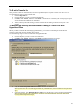
1. Insert the data disc into your CD/DVD-ROM drive.
2. From the Start menu, click Run.
3. Type D:\Setup (where D: is the letter of the drive containing the data disc) in the command line text box
and then click OK. The Topo USA data setup screen displays.
4. Follow the on-screen directions to complete the data installation.
5. Click Finish when prompted. It is not necessary to restart your computer.
Route Tab
How do I create a road/trail route?
Use the following steps to create a route.
1. Click the Route tab and then click New/Edit. The New/Edit Route dialog area displays.
2. Click File, click New, and then type the name for your route in the Name text box.
3.
Click the Start tool
and then click the point on the map where you want to begin your route.
OR
Type your start location in the Start drop-down text box. If you type an address, it must be in one of the
following formats: street address, city, state OR street address, ZIP Code.
4.
Click the Finish tool
and then click the spot on the map where you want to end your route.
OR
Type your finish location in the Finish drop-down text box. If you type an address, it must be in one of the
following formats: street address, city, state OR street address, ZIP Code.
Select a route type (direct, trail, road-shortest, or road-quickest) from the available drop-down list.
Note: Your route will fail to calculate if you select a route type that your dataset does not support.
If you do not have the Auto Calc check box selected, click Calculate .
OR
If you do not have the Auto Calc check box selected, right-click the route, select Manage Route, and then
select CalculateTrail, Calculate Direct, Calculate Road Quickest,or Calculate Road Shortestfrom the
shortcut menu.
Note: If Topo USA 5.0 is unable to find an exact match for the item that you typed, a dialog box displays
with a list of the closest matches. Scroll through the list of search results until you find the one you want to
locate, click the item to select it, and then click OK.
Click Directions to view the route directions.
AND/OR
Click Advanced to display the advanced routing options.
AND/OR
Click Back on Track to add your current GPS position as a stop to the current route.
5.
6.
7.
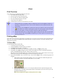
Print Tab
How can I print my route?
Use the following steps to print an existing route.
1. Click the Print tab and then click the Route subtab.
Note: If you do not have a route on this Map File, the print route options are unavailable.
2. Select the route you want to print from the Na me drop-down list.
Note: If the route you want to print is not available in the Name drop-down list, you may not have the
correct Map File open.
3. Under Options, select from one of the following choices:
2
Getting Started
•
4.
5.
Overview—Provides an optimized map of your route and the route summary (trip distance, trip
time, start, total stops, and finish).
• Travel Package—Provides maps of the route with corresponding directions.
• Directions—Provides action-based directions (turn, merge, bear, depart, arrive, and continue)
including the time frame for each action.
Note: Route directions can be saved as a text file.
• Route Maps —Provides detailed maps in the direction of travel of the route along with directions
which appear in the map margin. Route maps are not printed North Up like other printed maps.
They are printed so that the direction of travel is always at the top of the printed map.
Select the miles per page that you want your route to cover from the Miles Per Page drop-down list.
Click Print.
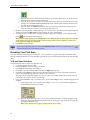
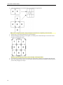
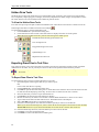
Draw Tab
How do I add a road/trail to my map?
Use the following steps to add routable roads or trails to the map.
1. Click the Draw tab to open the Draw dialog area.
2. Click and hold the Routable Roads/Trails/Waypoints/Tracks tool to view its hidden options. Select the
Routable Roads tool
OR
3.
4.
5.
6.
to create a routable road.
Click and hold the Routable Roads/Trails/Waypoints/Tracks tool and select the Routable Trails tool
.
Type the name of the road/trail you want to add in the Road (Trail) Name text box.
Hover the mouse pointer over existing roads/trails to display the yellow diamond symbol . The yellow
diamond symbol indicates where on an existing road/trail the point for your new road/trail will connect
(connection point).
Note: It is necessary for the new road to be connected to an existing non-limited access road for routing on
the new road to occur.
Once you have located the connection point for your new road/trail, click the map to place the first point.
Click point-to-point or drag to add the new road to the road/trail layer.
To finish the line draw for the new road/trail, enter the last point on the map screen and click Done.
GPS Tab
How do I start tracking with my GPS device?
In order to begin properly tracking with your GPS device, you must first configure the GPS tab with your
appropriate device settings. For more information, see Initializing GPS on page 116.
How do I import waypoints from my GPS device?
Use the following steps to receive waypoints from your GPS device.
1. Connect your GPS receiver to your computer.
2. If you are using a third-party GPS receiver, you may have to use specific settings. For example, if you are
using a GARMIN GPS receiver, set your GARMIN receiver interface to GRMN/GRMN.
3. Click the GPS tab, click Settings, and then click Exchange. The Exc hange Wizard displays.
4. Under Device Type, select GPS.
5. Select Receive from Device.
6. Select Waypoints from the Object drop-down list.
7. Select Draw File if you want to save the waypoints as a draw file (or User Map Data - Waypoints if you
want to save the waypoints as a waypoint file) from the Save As drop-down list.
8. Click Next.
9. If you selected Draw File in step 7, select the draw file you want to add the waypoint information to from
the Draw File drop-down list. If you want to create a new draw file, select New from the Draw File dropdown list and type the new draw file name in the available text box.
OR
If you selected User Map Data - Waypoints in step 7, select the waypoint file you want to add the waypoint
information to from the Waypoint File drop-down lis t. If you want to create a new Waypoint file, select
3
Topo USA 5.0 User Guide
New from the Waypoint File drop-down list and type the new waypoint file name in the New Waypoint
File text box.
10. Click Receive From Device.
11. Repeats steps 9–10 for each waypoint file you want to receive.
12. Click Finish.
Profile Tab
How do I view a profile of a route I've created?
1. Center the route you want to profile on the map.
2. Click the Profile tab.
3. Select a route on the map to generate its profile. When the object is selected, it is highlighted and the
Profile graph displays in the Profile dialog area.
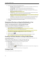
3-D Tab
How can I view a horizontal perspective of the map in 3-D?
1. Click the 3-D tab to open the 3-D dialog area.
2. Select the Rotate map center view option.
3. Use one or more of the following options to change your 3-D map view.
• Drag the Pitch tool to change the pitch of the 3-D map.
• Drag the Rotation tool to rotate the map on its center so you can view it from different compass
directions (N, S, E, W, SE, SW, NE, NW). The arrow and letter(s) indicate the direction toward
which you are viewing the map.
• Click one of the Vertical Exaggeration options (1x, 2x, 4x, or 8x) to exaggerate the terrain.
• Select the Shading check box to add shading to the 3-D map for better depth perception of objects
on the map.
• Select the Use Hardware Acceleration check box if you have a 3-D graphics acceleration card.
Choosing this option enhances the performance and resolution of the 3-D map window.
4. Click View 3 -D Map to view the 3-D map in the secondary map window.
How can I view a center perspective of the map in 3-D?
1. Click the 3-D tab to open the 3-D dialog area.
2. Select the Orbit map center view option.
3. Use one or more of the following options to change your 3-D map view.
• Drag the Pitch tool to change the pitch of the 3-D map.
• Drag the Rotation tool to rotate the map on its center so you can view it from different compass
directions (N, S, E, W, SE, SW, NE, NW). The arrow and letter(s) indicate the direction toward
which you are viewing the map.
• Click one of the Vertical Exaggeration options (1x, 2x, 4x, or 8x) to exaggerate the terrain.
• Select the Shading check box to add shading to the 3-D map for better depth perception of objects
on the map.
• Select the Use Hardware Acceleration check box if you have a 3-D graphics acceleration card.
Choosing this option enhances the performance and resolution of the 3-D map window.
4. Click View 3 -D Map to view the 3-D map in the secondary map window.
NetLink Tab
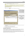
How can I download ADPs?
1. Click the NetLink tab. The NetLink dialog area displays.
2. Click the Datasets subtab. The Datasets dialog area displays.
3. Center the map on the location you want to select your customized dataset coverage from.
4. Select the desired delivery method (download or CD-ROM) from the available drop-down list.
5. Select the desired type of dataset from the Datasets drop-down list.
6. If you selected to download your customized dataset, zoom your map to zoom level 11-0 or greater.
OR
4
Getting Started
If you selected to receive your customized dataset on a CD-ROM, zoom your map to zoom level 8-0 or
greater.
7.
Click the Selecttool
.
Note: Areas with partial coverage display as map rectangles with a translucent gray diagonal pattern within
the cells and are surrounded by grid lines. Areas without coverage are highlighted gray.
8. Drag your cursor over multiple map rectangles or click each individual map rectangle you want to include
in your customized dataset. As you select your coverage area, the dialog area displays the total size in MB,
total size in square kilometers, total price (not including any minimum charges), download time (if
applicable), and number of CDs (if applicable).
Note: You can click a selected rectangle to clear it from the coverage area, drag your cursor over the map
rectangles you want to clear from the coverage area, or click Clear to clear all selected rectangles from the
coverage area. Any selections you have already added to your selection list are not effected.
9. Click Add to List to add your customized dataset selections to your selection list.
Note: You must click Add to List each time you want to add a different delivery method to your selection
list.
10. Name your selection when prompted and click OK.
11. Click Shop On to return to the NetLink dialog area to create additional customized datasets. Repeat steps
3–8 for each additional dataset.
OR
Click Checkout to proceed to the DeLorme Web site to purchase your datasets.
How can I download free campground data?
You can use the NetLink tab to gain access to special offers, such as free, downloadable USA Campground data.
Use the following steps to download the free data.
1. Click the NetLink tab.
2. Click the link to view data available for download.
3. Select U.S. Campground Data.
4. Save the USACampgrounds.exe file to your desktop.
5. Double-click the file on your desktop and install the data. If Topo USA 5.0 is already installed, the
campground data is automatically connected to the program for viewing and searching use.
Map Display Tab
How can I change the coordinate system of the map?
Use the following steps to change how coordinate measurement units dis play.
1. Click the Map Display tab and then click Units to display the Units options.
2. Select the desired coordinate display format from the Coords drop-down list.
§ Degrees
§ Degrees, Minutes
§ Deg, Min, Sec
§ UTM/UPS (Universal Transverse Mercator/Universal Polar Stereographic)
§ MGRS (Military Grid Reference System)
§ USNG (United States National Grid)
§ SPCS (State Plane Coordinate System)
Note: When you select SPCS, an additional drop-down box displays for Zone.
3. Under Coordinates, select the desired datum from the Datumdrop-down list.
§ WGS84 (World Geodetic System of 1984)
§ NAD27 (North American Datum of 1927), which also includes OOH (Old Hawaiian) Datum
when in Hawaii
§ NAD83 (North American Datum of 1983)
4. If you have selected SPCS, select the desired state zone from the Zone drop-down box.
Note: No SPCS coordinates display until you have chosen a zone.
Handheld Export Tab
How do I export a map in Topo USA for use on my handheld device?
5
Topo USA 5.0 User Guide
Important: You must have XMap® Handheld Pro (available separately from DeLorme) to view raster and
vector Topo USA 5.0 maps (or Street Atlas USA 2004 Handheld to view vector maps) on your handheld
device.
Use the following steps to export a map to a Palm OS or Pocket PC device.
1. In Topo USA 5.0, click the Handheld Export tab. The Handheld Export dialog area displays.
2. Locate the desired map area.
3. If you are using split-window functionality, select whether you want to cut the map as it is displaying in the
Left (secondary) map window or the Right (primary) map window.
4. Under Select, select a zoom level from the Data Export Level drop-down list.
Note: If you are exporting a map at a routable zoom level, "routable" displays next to the applicable data at
zoom level option. If "routable" does not display next to your selected data export zoom level, you will not
be able to create a route with the exported map on your handheld device.
4. If raster data is available at the selected data export level, select the Only Cut Rasters check box to only
include raster data with your exported map.
5.
6.
7.
8.
Under Select, click the select tool
and select the rectangle(s) on the map that you want to export to
your handheld.
Note: Click Clear All to clear the selected rectangles from the map.
Under File, type the file name for your new file in the available text box.
Click Browse if you want to save the file in a location other than the default location of C:\DeLorme
Docs\Mobile Maps.
Click the save button
.
To cut another map, click the new file button
and repeat steps 3-8.
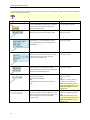
Helpful Tips
The following are helpful hints for using various functions of Topo USA 5.0. Some of the hints are available as a
pop-up tutorial when you click on a related function within the program.
Selecting the "don't show again" check box in a pop-up tutorial ensures that pop-up will not display
whenever you click on its related function. If you change your mind and want to view the pop-up
tutorials later, click the Reset All Pop-up Tutorials option in the Topo USA 5.0 Help menu. If you
want to disable all of the pop-up tutorials so they do not display, click the Shut Off All Pop-up
Tutorials option in the Help menu.
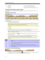
If you want to...
Zoom the map out/in quickly
Pan the map quickly
Know the best data zoom level to
view certain datasets
Measure the area/perimeter of a
specified location on the map
Update the coordinate format that
displays in the Control Panel
Adjust the size of the tab area
Show, hide, or reorder tabs
6
Use this tip...
You can drag the map cursor in an up-left direction to zoom the map out or
drag it in a down-right direction to zoom the map in.
If you position your cursor on the edge of the map, it becomes a white hand
that you can use to drag the map to the desired location.
Satellite Imagery (Sat 10) is best viewed at data zoom level 12-0.
3-D TopoQuads data is best viewed at data zoom level 13-0.
Aerial Imagery (DOQQ) is best viewed at data zoom level 15-0.
All three types of data can be viewed from data zoom level 6-0 to 16-0.
You can use the measure tool to draw a polygon on the map and determine
its area and perimeter. Just click point-by-point to draw the polygon on the
map and then double-click to close the polygon. The area and perimeter
dis play in the center of the polygon.
You can update your measurement preferences at any time using the Units
subtab in the Map Display tab.
You can adjust the size of the tab area by dragging the top or right side of the
tab area.
You can use the Tab Manager option in the Help menu to show, hide, or
reorder tabs.
Getting Started
If you want to...
Stop a page in a multi-page map
from printing
Add existing route and/or draw
files to your map file
Create a route using a road or trail
you have added to the map with the
Draw tab
Join/break linear objects on the
map
View a GPS log on the map
Determine the difference between
adding and inserting Stops/Vias
Create a route quickly
View the last map center
Quickly view information for a
location on the map.
Know if there are NetLink updates
available
Use this tip...
If you do not want to print all the pages in a multi-page map, you can click
the page(s) you do not want to print on the Layout graphic.
You can add existing route and/or draw files to your map files by clicking
the Add button and selecting the Draw File or Route File option.
When drawing a routable road/trail, be sure to click each existing road it
crosses to ensure that routing can be done on the new road/trail. When you
open a track you've imported from your GPS device, be sure to join the
imported line with existing lines by right-clicking the intersection(s) and
selecting Manage Draw/Join.
You can join and break linear objects using keys on your keyboard. Select
the item(s) you want to join/break (press the SHIFT key to select multiple
items) and then press CTRL+N to join or CTRL+B to break.
You can use the Draw tab to import a GPS log file and view it as a line
object on the map.
When Stops/Vias are added to a route, they are placed in the order they were
added to the route. When Stops/Vias are inserted in a route, Topo USA
places them in the order they would be approached between the Start and
Finish points of the route.
For quick route creation, right-click the map and select one of the Create
Route options or click the Start (green), Stop (yellow), Via (white), or Finish
(red) buttons in the Route tab.
Press the middle button in the Compass Rose (in the Control Panel)to center
the map on the previous map view. This button performs an undo function
for the last pan or zoom (up to 256 times).
Hover your cursor over objects on the map to see information (such as road
names, city/town, details about draw objects, etc.) in the status line that
appears at the bottom of the map, just above the tab area.
Check to see if "NetLink" is displayed as blue on the NetLink tab. If it is,
updates/offers are available.
Running Topo USA 5.0
As soon as you have installed Topo USA 5.0, you can read your Topo USA data, Sat 10 data, or data discs from
other DeLorme mapping products such as 3-D TopoQuads ® and Topo USA 4.0 .
To Run Topo USA 5.0
Use the following steps to access Topo USA 5.0.
1. Insert a compatible data disc into your CD/DVD-ROM drive.
2. If you installed a desktop shortcut, double-click the Topo USA 5.0 icon.
OR
From the Start menu, point to Programs , point to DeLorme, point to Topo USA 5.0, and then click Topo
USA 5.0.
Exiting Topo USA 5.0
To exit the program, click the close button
in the upper-right corner of the screen.
A Save Changes dialog box displays if only one item was changed, such as the data zoom level, resulting in a
change to the map file.
• Click Yes to save any changes to the item.
• Click No to discard changes to the item.
• Click Cancel to return to Topo USA 5.0. Changes are not saved.
An Exit dialog box displays if more than one item has been updated. All updated files are listed and are selected by
default.
7
Topo USA 5.0 User Guide
•
•
•
Click Save and Exit to save any changes for the selected files and close the program.
Note: Clear the check box of any item you do not want saved prior to using this option.
Click Exit without Saving to close the program without saving any file changes.
Click Cancel to return to Topo USA 5.0. No files are saved.
Saving Topo USA Data to Your Hard Disk Drive
Your Topo USA data can be saved to your hard disk drive so that it is readily available without inserting it into your
CD/DVD-ROM drive when you need it.
To Save Topo USA Data
Use the following steps to save Topo USA data to your hard disk drive.
1. Insert the Topo USA data disc into your CD/DVD-ROM drive.
2. From the Start menu, click Run.
3. Type D:\Setup (where D: is the letter of the drive containing the data disc) in the command line text box
and then click OK. The Topo USA data setup screen displays.
4. Follow the screen directions to complete the data installation.
5. Click Finish when prompted. It is not necessary to restart your computer.
6. Once the data is installed, connect the data using the Data Locations feature in the Map Files tab.
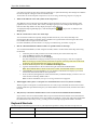
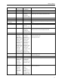
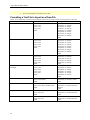
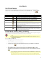
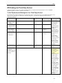
Topo USA 5.0 File Directories
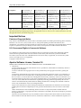
Topo USA 5.0 allows you to save route files, draw files, print files, and so forth in designated directories. The table
below describes the different file types the program supports, which default directory each file type is saved in, and
the file extension(s).
File Type
Draw files
Export files (Draw)
GPS Log files
Map File files
Print files
Default Directory
C:\DeLorme Docs\Draw
C:\DeLorme Docs\Draw
C:\DeLorme Docs\ GPSLogs
C:\DeLorme Docs\Projects
C:\DeLorme Docs\Print
Route files
Symbol files
Transfer files
C:\DeLorme Docs\Navigation
C:\DeLorme Docs\Symbols
C:\DeLorme Docs\Projects
Extension(s)
.an1
.txt
.gpl
.tpx
.txt (route directions)
.bmp/.jpg (all other files)
.anr
.dim
.dmt
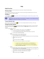
Frequently Asked Questions
Below is a list of the questions which are asked most frequently by our customers about the Topo USA ® family of
products.
• How do I save my data on my hard disk drive?
How you save your data will depend on what dataset you are using with Topo USA 5.0. Once the dataset is
installed, you must use the Data Locations feature in the Map Files tab to connect the data to Topo USA.
If your dataset is not listed below, see the dataset's documentation for information on saving it to your hard
disk drive.
To Save Topo USA Data On Your Hard Disk Drive
1. Insert the Topo USA data disc into your CD/DVD-ROM drive.
2. From the Start menu, click Run.
3. Type D:\Setup (where D: is the letter of the drive containing the data disc) in the command line
text box and then click OK. The Topo USA data setup screen displays.
4. Follow the screen directions to complete the data installation.
5. Click Finish when prompted. It is not necessary to restart your computer.
To Save 3-D TopoQuads Data On Your Hard Disk Drive
6. Using Windows Explorer, create a folder on your hard disk drive called 3-D TopoQuads Data.
8
Getting Started
7.
Within the 3-D TopoQuads Data folder, create a subfolder for your data DVD or create subfolders
for each of your regional data CDs. For example, the directory would look similar to, C:\3-D
TopoQuads Data\Region 1 or C:\3-D TopoQuads Data\DVD.
8. Insert the 3-D TopoQuads data disc into your CD/DVD-ROM drive.
9. Using Windows Explorer, browse to your CD/DVD-ROM drive.
10. Right-click the CD/DVD-ROM drive and select Copy from the shortcut menu.
11. Right-click the folder you created in step 2 and select Paste from the shortcut menu.
12. Repeat steps 3-6 for each 3-D TopoQuads data disc you would like to copy to your hard disk
drive.
•
How do I create a route on the map?
Topo USA 5.0 allows you to create a route by simply adding start and finish points. You can add stops or
vias to make your route more useful and realistic.
You can also create a route using right-click functionality while in any tab. Your route receives a default
name when creating it using right-click options. However, you can rename your route any time in the Route
tab to make it easier to retrieve.
For more information on adding a route to your map, see Creating a Route on page 131.
•
How do I find a specific location?
Topo USA 5.0 offers powerful search tools that enable you to locate a specific city/town, county, feature,
street address, ZIP Code, area code and exchange, street intersection, or coordinate location.
To access the search feature in Topo USA 5.0, click the Find tab. For more information on searching for
specific locations, see Using QuickSearch on page 45 and Using Advanced Search on page 46.
•
How do I bring in routes from another DeLorme program?
Routes you create using any of the following DeLorme programs can be brought into Topo USA 5.0: all
versions of XMap®; AAA Map'n'Go ® versions 5.0-7.0; Street Atlas USA ® versions 6.0-9.0, 2003, and 2004;
Topo USA ® 2.0-4.0; and 3-D TopoQuads® 2.0.
For more information on how to import routes, see Importing Routes on page 137.
•
How do I bring in draw layers created in another DeLorme program?
Draw layers can be brought in from many other DeLorme programs for use in Topo USA 5.0. For a
complete list of supported programs and more information on importing draw layers and other files into
Topo USA 5.0, see Importing Files to Draw Files on page 65.
•
How do I initialize my GPS receiver?
Each time you use your GPS receiver, you initialize it, which means you set your starting position on the
map by obtaining the initial coordinates of your location. This can be done automatically or manually.
For more information, see Initializing GPS on page 116.
•
How can I get information about an item on the map?
You can right-click virtually any point, symbol, feature, or area on the map and then click Info to identify it
and view detailed information about it. The type of descriptive information varies, depending on the item
you have right-clicked.
You can also copy the information and paste it into another program, such as a word processor.
•
What is a map file?
Topo USA 5.0 lets you save all of the work you have done in the mapping application as a single
workspace so you can open it again later. These saved workspaces are called map files.
A map file consists of the following items: coordinates of the map center, current data zoom level, current
magnification, map display preferences, any added items: such as draw layer(s), route(s), and so forth. As
9
Topo USA 5.0 User Guide
you create new routes or draw layers, change preferences, or pan/zoom the map, these changes are added to
the current map file. Changes can be saved or discarded.
To learn how to create a map file in Topo USA 5.0, see Creating and Deleting Map Files on page 38.
•
What do the different colors and symbols on the map mean?
The different colors on the map represent different areas of land use or land cover (for example: parks,
population areas, water, forests, and so forth). The Map Legend provides examples and descriptions of
these and other map features as they display on maps in Topo USA 5.0.
To display the Map Legend Help topic, click the Help button
in Topo USA 5.0 and then click
MapLegend.
•
How do I zoom in for a closer view of the map?
You can use the Zoom tools to quickly change the data zoom level (1-0 to 20-0) of the map view.
Increasing the data zoom level number shows a smaller area at greater detail. Decreasing the data zoom
level number shows a larger area at lesser detail.
For more information, see Data Zoom Level on page 35 and Zooming In and Out on page 35.
•
How do I find all landmarks within ten miles of a specific location on the map?
You can find all landmarks (or other categories of items) within a 10 mile radius of the map center using
the Find tab.
1. Center the place or item you want to use as the center of your search on the map view.
2. Click the Find tab and then click Advanced.
3. From the Find drop-down list, select Category.
For more information on category searches, see Keywords for Category Searches on page 48.
Note: In all category searches, the Keywords field is optional. If the Keywords field is left blank,
all objects in the selected Within area display in the Results list.
4. From the Within drop-down list, select Distance from Map Center.
5. Type the desired distance in the text field to the right of the Find and Within fields.
Note: The minimum distance which can be used is 50 feet; the maximum distance is 100 miles.
6. Click Search or press the ENTER key on your keyboard. The Results list displays your search
results with closest match items at the top of the list.
7. Scroll (or browse) through the list of search results until you find the item(s) you want to view. To
center an item on the map, double-click it.
Note: For more information, see Tips on Viewing Find Results on page 49.
•
What happens when I place a route point on a location that isn't on a street (such as in a field)?
When you place a route point in a location that isn't on a street, Topo USA finds the closest street to that
location, marks the space between the point you clicked and the street with X marks, and starts the route at
the street.
•
Why does my route fail to calculate when I create a route between an island and the mainland?
If you create a route on an island without roads, Topo USA will look for the nearest road to that island to
place the route point. If the nearest road is not routable (for example, it is the only road on the island and/or
the island does not have ferry access), you will get an error message saying "Route failed to calculate."
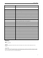
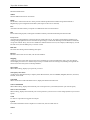
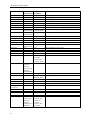
Keyboard Shortcuts
The following are shortcut keys you can use on your keyboard to perform a variety of actions in Topo USA 5.0.
Shortcut key(s)
Action
F1
View the online Help topics
F10
Resize the tab area to its default
10
Getting Started
Shortcut key(s)
Action
F11
Pick up the top corner between overview map and the tab for resizing
F12
Get focus to map
CTRL+TAB
Tab forward through the tabs
CTRL+SHIFT+TAB
Tab backward through the tabs
CTRL + B
Break line object
CTRL + C
Copy selected text in text field or query results list; copy selected draw object
CTRL + G
Start/stop GPS (GPS command)
CTRL + P
Print map at current layout
CTRL + S
Save current map file
CTRL + V
CTRL + W
Paste copied text into selected text field in the tab area or MapNote on the
map; paste copied draw object over the original one
Toggle auto pan on/off (GPS command)
CTRL + X
Cut selected text; cut selected draw object
CTRL + Z
Undo/redo text edit; undo/redo drawing line or polygon object
ALT + F1
Opens the Help menu
ALT + F4
Closes the application
ALT + G
Places a waypoint at the current GPS location (when tracking)
ALT + LEFT ARROW
Pan the map left
ALT + RIGHT ARROW
Pan the map right
ALT + UP ARROW
Pan the map up
ALT + DOWN ARROW
Pan the map down
ALT + PAGE DOWN
Zoom the map in
ALT + PAGE UP
Zoom the map out
SHIFT+TAB
Go back through the controls on the tab
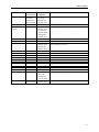
Glossary
ADT
Alaska daylight time
Almanac
Data downloaded from the satellites that contains the identity codes, location, and time information for each
satellite.
Arctic Circle
Parallel, or line of latitude around the Earth, at approximately 66°30' N. Because of the Earth's inclination of about
23 1/2° to the vertical, it marks the southern limit of the area within which, for one day or more each year, the Sun
does not set (about June 21) or rise (about December 21).
11
Topo USA 5.0 User Guide
AST
Alaska standard time
Attach
As in attaching a draw road to existing roads.
Average Speed field
When tracking with GPS, displays your average speed.
Azimuth
The direction of travel or the direction between two points in reference to true or magnetic north. When expressed in
degrees, its value ranges from 0 to 360 . A compass heading is an azimuth. In most places the word bearing has
grown to mean the same thing as azimuth. However, azimuth is always measured from true or magnetic north in a
clockwise direction. For examp le; due east is 90 and due west is 270 . See also, Bearing.
Battery Voltage field
Displays the current voltage of your 3Com Palm Computing Organizer's batteries.
Bearing
When tracking, bearing displays the direction of travel between your current position and your next waypoint,
relative to true or magnetic North.
Like a azimuth, a bearing is measured in reference to true or magnetic north, but its value never goes over 90 . A
bearing is always measured from the cardinal directions of north or south. A typical bearing would be N45 E, which
is the same as an azimuth of 45 . The bearing S45 W is an azimuth of 225 . The use of the word bearing has changed
over the years and now means the same as azimuth.
Bread crumb trail
A set of dots that display on your computer screen to record your progress as you travel.
CDT
Central daylight time
Coordinates
A set of numbers (e.g., latitude and longitude) used to identify the specific location of a point.
Course
The azimuth and length of a line, considered together.
CST
Central standard time
Date field
When connected to a DeLorme GPS receiver, displays the current date.
Differential GPS (DGPS)
A technique to improve GPS accuracy that uses pseudo-range errors recorded at a known location to improve the
measurements made by other GPS receivers within the same general geographic area.
Dilution of Precision (DOP)
The total effect of all error sources in locating a position.
Dist to Finish
When GPS tracking, displays the distance from your current position to your Fin ish.
Dist to Next Turn
When GPS tracking, displays the distance from your current position to your next turn or route change.
12
Getting Started
DOP
Dilution Of Precision
Download
To transfer information from a remote unit, such as a GPS receiver, to a computer.
EDT
Eastern daylight time
Elevation field (GPS)
When GPS tracking, displays your current elevation (due to Selective Availability which can vary as much as 512
feet (156 meters); however, 95 percent of the time you can expect greater accuracy.) Elevation is the height above
sea-level.
Ephemeris
Data which indicates the position and status of satellites.
EST
Eastern standard time
GMT
Greenwich mean time; used as the standard of time throughout the world.
GPS
Global Positioning System; a "constellation" of orbiting satellites used to calculate a precise position on or near the
earth's surface.
HDOP
The measure of how much the geometry of the satellites affects the horizontal position estimate.
Heading
The direction you are traveling at the moment.
Initialize
To set to a starting position, as in obtaining initial coordinates for a GPS receiver.
Latitude
Position north or south of the equator in degrees, minutes, and seconds.
Log
A record of the speed, direction, and route of travel as obtained via GPS.
Logging
Recording the speed, direction, and route traveled using GPS.
Longitude
Position east or west of the prime meridian in degrees, minutes, and seconds.
Maximum Speed field
When GPS tracking, displays your maximum speed.
MDT
Mountain daylight time
MST
13
Topo USA 5.0 User Guide
Mountain standard time
NMEA
National Marine Electronics Association
PDOP
The measure of how much the error in the position estimate produced from satellite range measurements is
amplified by a poor arrangement of satellites (with respect to the receiver antenna).
Port
A hardware interface used by a computer to communicate with an external device.
PPS
Precise Positioning System; radio signals available to military and other authorized personnel for GPS.
Proxy server
An application that breaks the connection between sender and receiver. All input is forwarded out a different port,
closing a straight path between two networks and preventing a cracker from obtaining internal addresses and details
of a private network. Proxy servers are available for common Internet services; for example, an HTTP proxy is used
for Web access, and an SMTP proxy is used for e-mail.
Real time
The actual time during which something takes place.
Receiver
Hardware device that receives data, such as from satellites.
Snapping
Attaching a point on one draw object to the exact coordinates of a point in another draw object. You can snap the
central shape point of an arc to another object or snap a routable road to an existing road, enabling routing from the
drawn road to the road system on the map database .
Speed field
When GPS tracking, displays your speed as you travel.
Third-party GPS device
A GPS receiver manufactured by a company other than DeLorme, such as GARMIN, Magellan, Brunton, Lowrance,
Trimble, and so forth.
Time field
When connected to a DeLorme GPS receiver, displays the Greenwich mean time.
Time to Finish field
When GPS tracking, displays the time from your current position to your Finish (based on your current speed).
Time to Next Turn field
When tracking, displays the time from your current position to your next turn or route change (based on your current
speed).
Track
To observe or plot the moving path of an object.
Upload
To transfer information from a computer to a remote unit, such as a GPS receiver.
VDOP
14
Getting Started
The measure of how much the geometry of the satellites affects the vertical position estimate.
Waypoints
Marked positions with specific coordinates that can be downloaded or uploaded.
Travel Contacts
This Help topic contains hotel, car rental, and airline information.
Hotel Information
Hotel Name
AmeriHost Inn
AmeriSuites
Baymont Inn & Suites
Best Inns and Suites
Best Western International, Inc.
Clarion Hotels
Comfort Inns
Country Inns & Suites
Courtyard by Marriott
Crowne Plaza
Days Inn
Doubletree Hotels
Drury Inn
Econo Lodge
Embassy Suites
Extended StayAmerica
Fairfield Inn
Fairmont Hotels
Hampton Inn
Hawthorn Suites
Hilton Hotels
Holiday Inn
Holiday Inn Express
Homewood Suites
Howard Johnson
Hyatt Hotels and Resorts
Inter-Continental Hotels
Jumer's Hotels
La Quinta Inns
Loews Hotel
MainStay Suites
Marriott Hotels
Microtel Inn
Motel 6
Omni Hotels
Park Plaza International
Quality Inn
Radisson Hotels International
Raffles International Hotels and Resorts
Ramada Hotels
Phone Number
800-434-5800
800-833-1516
866-999-1111
800-BEST INN
800-780-7234
800-CLARION
800-228-5150
888-201-1746
888-236-2427
800-2 CROWNE
800-329-7466
800-222-TREE
800-DRURY INN
800-55 ECONO
800-EMBASSY
800-EXT STAY
800-228-2800
800-257-7544
800-HAMPTON
800-527-1133
800-774-1500
800-HOLIDAY
800-HOLIDAY
800-225-5466
800-446-4656
800-233-1234
888-567-8725
800-AT JUMER
800-531-5900
800-23 LOEWS
800-660-6246
888-236-2427
(888) 771-7171
800-4MOTEL6
800-THE-OMNI
800-670-PARK
800-228-5151
800-333-3333
800-637-9477
800-2-RAMADA
15
Topo USA 5.0 User Guide
Hotel Name
Red Roof Inn
Regal Hotels
Renaissance Hotels
Residence Inn by Marriott
Rodeway Inn
Sheraton Hotels & Motor Inns
Shoney's Inn
Signature Inn
Sleep Inn
Staybridge Suites
Super 8 Motels, Inc.
Travelodge & Viscount Hotels
W Hotels
Westin Hotels & Resorts
Wyndham Hotels and Resorts
Phone Number
800-RED ROOF
800-222-8888
800-HOTELS1
800-331-3131
800-228-2000
800-325-3535
800-552-4667
800-822-5252
800-SLEEP INN
800-238-8000
800-800-8000
800-578-7878
877 W HOTELS
888-625-5144
877-999-3223
Car Rental Information
Car Rental Company
Alamo
Avis
Budget
Dollar
Enterprise
Hertz
National
Payless
RentaWreck
Thrifty
Phone Number
800-GO ALAMO
800-230-4898
800-527-0700
800-800-3665
800-RENTACAR
800-654-3131
800-227-7368
800-729-5377
800-944-7501
800-847-4389
Airline Information
Airline Name
Airtran Airways
Alaska Airlines
America West Airlines
American Airlines
American Eagle
Continental Airlines
Delta Airlines
Hawaiian Airlines
Midwest Express Airlines
Northwest Airlines
Southwest Airlines
United Airlines
USAirways
Phone Number
800-AIRTRAN
800-252-7522
800-235-9292
800-433-7300
800-433-7300
800-525-0280
800-221-1212
800-367-5320
800-452-2022
800-225-2525
800-435-9792
800-864-8331
800-428-4322
Travel Condition Information
This list below provides phone number and Web site information by state/province for road conditions and road
construction forecasts in the United States and Canada.
16
Getting Started
State/Province
Alabama
Alaska
Alberta
Road
Construction
N/A
800-478-7674
780-427-2731
Arizona
Arkansas
British
Columbia
California
Colorado
888-411-7623
501-569-2000
604-660-9770
Connecticut
860-594-2676
Delaware
Florida
302-760-2080
511 (partial
coverage)
Lake City:
800-749-2967
Miami: 800435-2368
Orlando: 800780-7102
Southwest:
800-292-3368
Tampa: 800226-7220
Turnpike:
800-749-7453
I-75 or I-10:
800-475-0044
404-656-5267
Georgia
Hawaii
Idaho
Illinois
800-427-7623
303-573-7623
808-536-6566
Treasure
Valley: 208336-6600
All other
areas: 888432-7623
Toll-free
roads: 312368-4636
Toll-free
roads: 800452-4368
Toll
highways:
Road
Conditions
N/A
511
Calgary: 403246-5853
Edmonton:
780-471-6056
511
501-569-2000
604-660-9770
800-427-7623
Denver: 303639-111
877-315-7623
in-state: 800443-6817
outside CT:
860-594-2650
N/A
511 (partial
coverage)
Lake City:
800-749-2967
Miami: 800435-2368
Orlando: 800780-7102
Southwest:
800-292-3368
Tampa: 800226-7220
Turnpike: 800749-7453
I-75 or I-10:
800-475-0044
404-635-6800
808-536-6566
Treasure
Valley: 208336-6600
All other areas:
888-432-7623
Toll-free
roads:312-3684636
Toll-free
roads:800-4524368
Toll highways:
800-865-5394
Web Site
www.dot.state.al.us
www.dot.state.ak.us
www.ama.ab.ca
www.tu.gov.ab.ca/roads/roadconditions.asp
www.azfms.com
www.arkansasinterstates.com
www.th.gov.bc.ca/bchighways/roadreports/roadreports.
htm
www.dot.ca.gov/hq/roadinfo
www.cotrip.org
www.dot.state.ct.us/trav_info/index.html
www.dot.state.co.us/TravelInfo/Index.htm
www.deldot.net/static/travel.html
www.dot.state.fl.us
www.myflorida.com
www.fhp.state.fl.us
www.georgia -navigator.com
www.dot.state.ga.us
N/A
164.165.237.41/roadreport
www.illinoisroads.info
www.dot.state.il.us
17
Topo USA 5.0 User Guide
State/Province
Indiana
Iowa
Kansas
Kentucky
Louisiana
Maine
Manitoba
Maryland
Massachusetts
Michigan
Minnesota
Mississippi
Missouri
Montana
Nebraska
Nevada
New Brunswick
New Hampshire
New Jersey
New Mexico
New York
Newfoundland
North Carolina
North Dakota
Northwest
Territories
Nova Scotia
Nunavut
Ohio
Oklahoma
Ontario
18
Road
Construction
800-865-5394
317-232-8300
511
800-585-7623
511
800-469-4828
511
877-627-6237
204-945-3704
800-323-6742
410-545-0300
617-374-1234
800-411-4823
511
601-987-1211
888-275-6636
800-222-6400
511
511
877-687-6237
N/A
N/A
Road
Conditions
Web Site
317-232-8300
511
800-585-7623
511
800-469-4828
511
877-627-6237
204-945-3704
800-327-3125
www.in.gov/dot/motoristinfo
www.dot.state.ia.us/roadcons.htm
kanroad.org
www.kytc.state.ky.us
www.dotd.state.la.us
www.state.me.us/mdot/homepage.htm
www.gov.mb.ca/tgs/hwyinfo/roadinfo1.html
617-374-1234
800-411-4823
511
601-987-1211
888-275-6636
N/A
www.michigan.gov/mdot
www.dot.state.mn.us
www.gomdot.com
www.modot.state.mo.us
511
511
877-687-6237
800-561-4063
In state: 800918-9993
Outside NH:
603-271-6900
N/A
www.mdt.state.mt.us/travinfo
www.dor.state.ne.us
www.nevadadot.com/traveler
www.gnb.ca/0113/roadcond/road-conditions-e.asp
www.state.nh.us/dot/traveler.htm
www.nmshtd.state.nm.us
www.dot.state.ny.us/roads/roads.html
N/A
919-733-2210
511
N/A
800-432-4269
NY Thruway:
800-847-8929
N/A
N/A
511
800-661-0750
N/A
888-252-9869
888-264-7623
N/A
Within
Canada: 800268-1376
Outside
Canada: 416235-4686
902-424-3933
888-252-9869
888-264-7623
405-425-2385
Within
Canada: 800268-1376
Outside
Canada: 416235-4686
www.gov.ns.ca/tran/roadconditions
http://www.gov.nu.ca/Nunavut
N/A
www.okladot.state.ok.us
N/A
Central: 732308-4074
Northern:
973-770-5025
Southern:
609-866-4940
800-432-4269
N/A
www.sha.state.md.us
www.state.nj.us/transportation
www.roads.gov.nf.ca
www.doh.dot.state.nc.us/impact
www.state.nd.us/dot/road.html
www.gov.nt.ca/Transportation/index.html
Getting Started
State/Province
Oregon
Pennsylvania
Prince Edward
Island
Road
Construction
In state: 800977-6368
Outside OR:
503-588-2941
215-567-5678
N/A
Quebec
Rhode Island
Saskatchewan
418-684-2363
401-222-4545
N/A
South Carolina
South Dakota
Tennessee
Texas
Utah
Vermont
Virginia
Washington
West Virginia
Wisconsin
Wyoming
N/A
511
N/A
800-452-9292
511
N/A
800-367-7623
800-695-7623
N/A
800-762-3947
307-772-0824
Yukon Territory
867-456-7623
877-456-7623
Road
Conditions
In state: 800977-6368
Outside OR:
503-588-2941
215-567-5678
Charlottetown:
902-368-4750
Georgetown:
902-652-8960
Summerside:
902-888-8275
418-684-2363
N/A
In province:
888-335-7623
Outside SK:
306-933-8333
N/A
511
800-342-3258
800-452-9292
511
800-429-7623
800-367-7623
800-695-7623
877-982-7623
800-762-3947
In state: 888996-7623
Outside WY:
307-772-0824
867-456-7623
877-456-7623
Web Site
www.tripcheck.com
www.dot.state.pa.us
www.gov.pe.ca/roadconditions/index.php3
www.mtq.gouv.qc.ca/en/accueil/plansite.asp
www.dot.state.ri.us/webtraf/index.html
roadinfo.telenium.ca/shwyw.html
www.highways.gov.sk.ca
www.dot.state.sc.us
www.sddot.com/travinfo.asp
www.tdot.state.tn.us/information-office/const.htm
www.dot.state.tx.us/hcr/main.htm
www.dot.state.ut.us
www.aot.state.vt.us/travelinfo.htm
virginiadot.org/comtravel/default.asp
www.wsdot.wa.gov/traveler.htm
www.wvdot.com/6_motorists/6_motorists.htm
www.dot.state.wi.us
www.wyoroad.info/highway/text_road.html
www.gov.yk.ca/roadreport
19
Help
Help Overview
There are several ways to get more information on Topo USA 5.0 features and functionality.
On-Screen Help
Help is available in the dialog area of Topo USA 5.0 in the form of ToolTips and information boxes. For more
information, see On-Screen Help on page 23.
Help Menu
Click the Help button
on the title bar to view the online Help options available with Topo USA 5.0. Then,
click an item to select it.
To access a Help menu item using its underlined letter, click the Help button and then press the
underlined letter (for the desired item) on your keyboard. For example, to access the Map Legend, click
the Help button and then press the M key on your keyboard.
Context-Sensitive Help
Click the context -sensitive Help button
to receive overview Help information for the tab you are using.
Using the Help System
This Help system provides explanations of all of the features and functions of Topo USA 5.0. To access the Help
system, click the Help button
on the title bar and then click Help Topics, or press the F1 key on your
keyboard.
The Help system displays three tabs.
§ Contents
To view an outline of the Help system contents, click the Contents tab.
• To view the overview for a particular book, click the book.
• To view the additional topics under a particular book, double-click the book.
• To view a topic, click the desired page.
§ Index
Use the following steps to search the Help system index.
1. While in the Help system, click the Index tab.
2. Type a keyword in the entry field. The list automatically scrolls to the closest matching
entry.
3. Double-click the desired topic.
OR
Click the topic and then click Display.
OR
Click the topic and press the ENTER key on your keyboard.
Notes:
• If a topic has any secondary index references, a window displays the
secondary index options. Click the item of interest to display the topic.
• If you don't find what you're looking for in the index, click the Search tab
and try a search for your keyword.
§ Search
Use the following steps to search for particular words or phrases within topics in the Help system.
1. While in the Help system, click the Search tab.
2. Type a keyword in the entry field and then click List Topics or press the ENTER key on
your keyboard. A list of topics containing the keyword displays.
3. Double-click the desired topic under Select Topic to Display.
OR
Click the topic and then click Display.
21
Topo USA 5.0 User Guide
OR
Click the topic and press the ENTER key on your keyboard.
•
The Help system keeps a history of viewed topics. Click the Back button
•
backward through previous topics. Click the Forward button
to browse forward
through the topics previously viewed.
Print any of the Help Topics by selecting a topic or heading (next to the book symbol) and then
•
•
•
to browse
clicking the Print button
. You can choose to print only the selected topic or a heading
and all subtopics.
OR
Right-click the topic displaying in the right window to print only that topic.
Tip: Before clicking Print, expand any links in the topic which include information you want to
print within your topic.
While in the Help system, the pointer changes to a hand when it passes over text or graphics that
you can click for more information.
The Help Topics window is a standard window that can be moved or resized.
To exit Help, click the close button in the upper-right corner of the screen.
Help Documentation Conventions
To help you easily locate and interpret information, the Help system has been formatted with various words in all
capital letters, in color, in boldface type, and so forth. There are also hyperlinks which expand, jump to another
location within the same topic, or link you to other topics.
The table below defines each convention and its use.
The convention...
Is used for...
ALL CAPITALS
Acronyms, names of certain commands, and keys on the keyboard.
Note: Use of the plus sign (+) between key names indicates key combinations which
perform various actions. For example, in the directions "Press CTRL+SHIFT+F3 on
your keyboard," you must press and hold the CTRL and SHIFT keys while pressing
F3.
Bold
Command buttons, tab names, and options when used in procedures and exercise
steps. Also used for information that you type exactly into a particular field.
Headings and table headings are bold for emphasis.
Italic
Directory names and paths; used sparingly for emphasis; also used when referring to
titles of chapters, sections, and publications.
Blue underlined text
Hyperlinks. These links act differently depending on their context. When it is:
• Referenced with "for more information," the link always goes to another topic.
• Embedded in text, such as in the example "Open the file," the link either goes to
another topic or displays a secondary window with a definition or graphic.
Red underlined text
Drop-down text which expands within the same topic to reveal more information
(such as a procedure).
A note that applies to the entire Help topic. If there is mo re than one note, the Notes
symbol is used and the notes are bulleted.
symbol in a yellow
box
Note(s): in Yellow
A note within a procedure. If there is more than one note, the notes are bulleted.
Highlight
A tip that applies to the entire Help topic. If there is more than one tip, the Tips
symbol is used and the tips are bulleted.
symbol in a blue
box
22
Help
The convention...
Tip(s): in Blue Highlight
Is used for...
A tip within a procedure. If there is more than one tip, the tips are bulleted.
Topo USA 5.0 User Guide
The Topo USA 5.0 User Guide includes the entire Help system contents, modified for print format, in a portable
document format (.pdf). When the guide is accessed, Adobe® Acrobat® Reader launches. The User Guide contains a
table of contents and can be printed out as a hard-copy reference.
To access the User Guide, click the Help button
on the title bar and then click User Guide.
On-Screen Help
There are two ways to obtain on-screen Help while using Topo USA 5.0: ToolTips and information boxes.
ToolTips
When you point to any of the Topo USA 5.0 tools for a few seconds, a short label (ToolTip) displays on your screen
describing the tool. ToolTips also display in Topo USA 5.0 windows and dialog boxes when you point to a button,
icon, or other feature.
Information Boxes
Several of the Topo USA 5.0 tabs contain information boxes that often display to the left of the Overview Map (the
small map in the lower-right corner of your screen). Information boxes provide descriptions about the features and
functions of the selected tab.
Pop-up Tutorials
When you click on some functions in Topo USA 5.0, you will receive a pop-up tutorial providing a helpful tip for
using the functionality.
Note: Selecting the "don't show again" check box in a pop-up tutorial ensures that pop-up will not display whenever
you click on its related function. If you change your mind and want to view the pop-up tutorials later, click the Reset
All Pop-up Tutorials option in the Topo USA 5.0 Help menu. If you want to disable all of the pop-up tutorials so
they do not display, click the Shut Off All Pop-up Tutorials option in the Helpmenu.
23
Basic Functions
Basic Functions Overview
Map control in Topo USA 5.0 is accomplished by using standard mouse point-and-click functionality and the
Control Panel tools. Right-click options provide flexibility for labeling, routing, getting information, and so forth.
For more information, see other Basic Functions topics. If they are not currently displaying, double-click the Basic
Functions book.
To Control the Map
The following list details the basic functions for controlling map movement.
• The mouse is used to pan or center the map view. Click a spot on the map to center the map on that point.
• A white hand displays when you point near the edge of the map. When the hand is visible, drag the map in
the desired direction.
• Use the black view box in the Overview Map window to pan the map. Point anywhere on the view box.
•
When the pointer becomes a
, drag the view box to the desired location.
The mouse button also allows you to quickly zoom the map using drag and zoom functionality.
To Use the Tabs
Click on a tab to view the available functionality. If it is not possible to display all tabs, horizontal scroll arrows
display to the right of the last visible tab.
Drag and Zoom
One of the most convenient features of Topo USA 5.0 is the ability to quickly zoom in on the map by using drag and
zoom functionality. Zoom in by dragging the mouse in a down-right direction or zoom out by dragging the mouse in
an up-left direction.
To Zoom In
Zooming in increases the data zoom level number and shows a smaller geographic area at greater detail.
Use the following steps to zoom in.
1. Drag the mouse in a down-right direction on the map to encompass the area you want to display. A view
box displays on the screen and changes dimension as you move the mouse. A label displays the data zoom
level at the current map center.
2. Once you reach the desired area or data zoom level you want to display, release the mouse button. The area
you selected fills the map window, the map re-centers, and the map view adjusts to show the appropriate
level of detail.
Tip: You can move the view box to another location by pressing the SHIFT key at anytime during this
procedure.
To Zoom Out
Zooming out decreases the data zoom level number and shows a larger geographic area at less detail. The maximum
zoom-out level is 1-0.
Use the following steps to zoom out.
1. Drag the mouse in an up-left direction on the map. A staircase with a small square displays on the screen.
2. Continue dragging the mouse in an up-left direction. The small square moves up the steps, one step per data
zoom level. A label displays the data zoom level to the bottom-right of the staircase.
3. Once you reach the desired data zoom level you want to display, release the mouse button. The map view
adjusts to display the appropriate level of detail. The map center is retained on your screen.
Additional zoom features include the Data Zoom Level controls and the Zoom tools .
25
Topo USA 5.0 User Guide
Panning/Centering the Map
You can use any of the following methods in Topo USA 5.0 to pan (move) or center the map.
• Click anywhere on the current map view. The point at which you click becomes the new map center.
• When you point near the map edge, a white hand displays. Drag the hand to move the map in the desired
direction.
• Click anywhere on the Overview Map. The point where you click becomes the new map center. This
technique allows you to traverse greater distances with each mouse click than you can within the main map.
•
Point anywhere on the black view box in the Overview Map window. When the pointer becomes a
,
drag the view box to the desired location.
• Use the search feature in the Find tab to center the map on a particular location.
• Press ALT+ an arrow key (up, down, left, or right) to pan the map view in small increments in the desired
direction.
• While the Num Lock key is off, you can use the direction keys on your numeric keypad to move the map.
Press:
• ALT+UP ARROW to pan the map up.
• ALT+RIGHT ARROW to pan the map right.
• ALT+DOWN ARROW to pan the map down.
• ALT+LEFT ARROW to pan the map left.
Note: Verify the Num Lock key is off by checking that the Num Lock indicator light is turned off.
Control Panel
The Control Panel, located to the right of the map view, displays information pertinent to the current map view and
map cursor position. It also includes zoom and map pan buttons.
26
Basic Functions
Data Zoom Level—The current data zoom level of the map view; ranges between 2-0
(maximum zoom-out) and 16-0 (maximum zoom-in).
Zoom Tools—Buttons that quickly zoom out three levels, out one level, or in one level. For
more information, see Zooming In and Out on page 35.
Compass Rose—A group of nine buttons, eight with yellow arrows pointing outward. Click
one of the arrow buttons to pan the map in that direction. Click the middle button to center the
map on the previous map view. This button performs an undo function for the last pan or
zoom (up to 256 times).
True North Indicator —Indicates the position of North relative to the current map view.
When the map is rotated using the Map Rotation tool, the True North arrow indicates True
North in relation to the rotated map.
Map Rotation Tool—This drop-down list is used to change the orientation of the map
display by adjusting the degree of map rotation. The angle of map orientation is directly
related to the degrees of a compass; for example, 90 degrees is always East.
Map Coordinates—Coordinates for the current map cursor position display based on the
units chosen under Coordinates on the Units dialog area in the Map Display tab.
Elevation and Interval—Display in the measurement chosen under Measures on the Units
dialog area in the Map Display tab. The data zoom level affects interval display.
Split Window Button—Displays/hides the secondary map window. Lets you display two
sets of data for the same area simultaneously.
Measure Button—Measure linear distances and perimeter/area on the map. For more
information, see Measuring Distance and Area on page 28.
Print Screen Button—Prints the current view as it displays on the screen (the control panel,
tab area, map view(s), etc.).
Scale Bar—Indicates the distance one scale bar unit equals in the measurement chosen under
Measures on the Units dialog area in the Map Display tab.
For information on changing coordinate systems or distance measures, see Setting Units of Measure
Preferences on page 152.
Map Rotation Tool
Topo USA 5.0 allows you to change the orientation of the map display by adjusting the degree of map rotation. The
angle of map orientation is directly related to the degrees of a compass; 90 degrees is always East, 135 degrees is
Southeast, 180 degrees is South, and so forth. For example, when you select 90 degrees from the drop-down list, the
map rotates so that 90 degrees (East) is at the top of the screen.
To Change the Map Rotation
Use one of the following two methods to change the angle of map rotation.
•
•
Select an angle from the available drop-down list
(in 45 degree increments)
OR
Type a specific angle (from 0 to 359 degrees) in the entry field.
27
Topo USA 5.0 User Guide
•
•
The True North Indicator adjusts when a new degree of map rotation is set.
The black rectangle in the Overview Map window, indicating the current map view, also rotates
to match the angle of map rotation.
A rectangle drawn with the Polygon/Rectangle/Circle tool in the Draw tab is positioned in
relation to North.
•
Measuring Distance and Area
The Measure Tool allows you to measure linear distance and area on the map based on the units chosen under
Coordinates on the Units dialog area in the Map Display tab.
The snapping feature allows you to snap (attach) the point of a measurement line to a point on a road or trail or
another measurement object. Using the snapping feature helps to ensure a more accurate measurement of distance or
area.
The snap function is essential when measuring area. To measure area, you must completely enclose the desired area
by snapping your finish point to your starting point. For more information, see the procedure which immediately
follows.
You can disable the auto-snap function by holding down the ALT key on your keyboard while using the
Measure Tool.
To Measure Distance or Area
Use the following steps to measure linear distance or area on the map.
1. Verify you have the desired units of measure selected in the Map Display tab. For more information, see
Setting Units of Measure Preferences on page 152.
2.
3.
4.
On the Control Panel, click the Measure Tool
. The pointer changes to a
.
Click point-by-point to draw a measurement line on the map. A text box displays next to your pointer
indicating the total distance of the measurement taken.
Note: When you pass over a point in a road or trail, measurement line, or measurement area to which you
can snap, a yellow circle defines the snap point. Click to snap the point of the measure line to the road or
measurement object's point coordinate.
To end a measurement line, double-click the last point of the measurement line. The measure line displays
as a two-pixel wide yellow line and the total length of the line displays in a label at each endpoint of the
line.
OR
To end a measure area, hover over the starting point until the yellow snap circle displays and then
double-click the last point to the starting point. The closure area becomes transparently shaded, and the area
and perimeter measurements displays.
Instead of double-clicking to end measure mode, click the last point of your measure line or area and then
click the Measure Tool
•
•
.
Measure objects (lines and areas) are saved with the current map file. When a new file is
created, the measure objects do not display. If you want the same measure objects on your new
map file, you must recreate them.
When you right-click a measure object, a shortcut menu displays Delete Measurement and
Manage Draw/Copy to Draw Object options. For more information, see Right-Click Mouse
Options on page 29.
Using the Overview Map
The Overview Map is a smaller map in the lower-right corner of the screen, which offers a wide-angle view of your
current map view area. It is approximately three data zoom-levels out from the current map view.
• Click anywhere on the Overview Map and that point becomes the new map center. This
technique allows you to travel greater distances with each mouse click than you can within the
larger, current map view.
28
Basic Functions
•
Use the black view box in the Overview Map window to pan the map. Point anywhere on the
view box. When the pointer becomes a
, drag the view box to the desired location.
Using the Secondary Map
Topo USA 5.0 has split-window functionality which lets you open a secondary map window to view a second set of
data simultaneously. The secondary map displays in the left window and the primary map displays in the right
window.
The secondary map displays when you click the split-screen button
on the Control Panel.
Accessing Data Collections
When the split-window feature is activated, a bar displays on the top of the secondary map. This bar displays two
drop-down lists: one for swapping data and one for changing the map from 2-D to 3-D (and vice versa). The bar also
has zoom tools which work specifically with the secondary map window. All of the data collections that you have
saved to your hard disk drive are available from the data drop-down lis t.
Additional Facts About Split-Screen Functionality
The following list details split-window functionality and the interaction between the primary and secondary map
windows.
• Both windows are centered on the same coordinate position. Panning or rotating the primary map using the
tools in the Control Panel causes the same action on both maps.
• Using drag and zoom functionality or scrolling the map in the primary window changes the map in the
secondary window as well. Scrolling the secondary map also causes the primary map to pan.
• Using drag and zoom on the secondary map also affects the primary map.
• The secondary window has its own zoom level controls. You can change the zoom level of the secondary
map without affecting the zoom level in the primary window. However, after you have adjusted the zoom
level in the secondary window, the zoom tools on the Control Panel adjust the map incrementally. In other
words, if the secondary map is at zoom level 6-0 and the primary map at zoom level 8-0 and you click the
Zoom Out 1 tool, the secondary map displays at zoom level 5-0 and the primary map at 7-0.
•
•
•
You can use the measure tool
in either window and any line or polygon measured in one window also
displays in the other window.
The Overview Map is always associated with the primary window and only displays the visible primary
map data.
Other tab functionality may be affected by use of the split-screen function. The following list describes
impacts to other tabs in Topo USA 5.0.
§
§
§
§
§
Draw—The line and polygon draw tools work in either window. The Select tool
highlights
the same draw object on both maps and you can then manipulate "both" objects at the same time.
Draw files are created for both windows in the same project.
Route—You can create routes only in the primary window; routes do not display in the secondary
window.
GPS—You can log with GPS in the primary window; log playback displays in both windows.
3-D—The 3-D map always displays in the secondary map window.
Map Display—Settings selected in the Map Display tab affects the maps in both frames.
Right-Click Mouse Options
Right-click mouse options in Topo USA 5.0 make many functions more convenient. For example, you can add and
delete routes without going to the Route tab, add MapNotes without going to the Draw tab, and so forth.
To Use Right-Click Options for Map Features
Click the right mouse button while pointing to a draw object, road, river, city, or other map feature. A shortcut menu
displays near the selection point with the options available for that particular map feature.
29
Topo USA 5.0 User Guide
If there are multiple (layered) objects on the point that is right-clicked, additional menu options
corresponding to the map objects are available.
•
•
•
•
30
Add MapNote
The Add MapNote right-click option allows you to label map locations with various types of MapNotes.
Right-click the point on the map you want to label, point to Add MapNote, and then click one of the
available options.
Each MapNote type provides different information, as shown in the following table.
MapNote Type (Color)
MapNote Label Information
MapNote (light blue)
Name of feature or its type, if unnamed.
Not always available.
Note: If there is no feature type, no MapNote displays. This is
most noticeable when right-clicking on land.
Detailed MapNote
Name, feature name, feature category, and measurement
(light blue)
information, for example: Great Cranberry Island, Land or
Not always available.
Island, Earth Surface, 1.71 square miles.
Where Am I MapNote (light blue)
City, county, and state names, plus the ZIP Code.
Coordinate MapNote (light blue)
Coordinate information, based on the current coordinate format
chosen in the Map Display tab.
Blank MapNote (white)
A blank label, which you can edit yourself.
Manage Route
• To hide a route, right-click the route and then click Hide Route.
• To activate an inactive route, right-click the desired inactive route and then click Activate Route .
• To delete a route, right-click the route and then click Delete Route.
• To convert a Stop to a Via, right-click the Stop/Via and then click Convert to Stop or Convert to
Via.
• To delete a Stop or a Via, right-click the Stop/Via and then click Delete Stop or Delete Via.
• To calculate the distance between the Start and Finish points of a trail, right-click the trail and then
click Calculate Trail.
• To calculate the distance between the Start and Finish points of a direct route, right-click the direct
route and then click Calculate Direct.
• To calculate the quickest route between your Start and Finish points on a road route, right-click the
route and then clic k Calculate Road Quickest.
• To calculate the shortest distance between your Start and Finish points on a road route, right-click the
route and then click Calculate Road Shortest.
Manage Draw
• To make changes to symbol or MapNote text, right-click the desired item, click Manage Draw, and
then click Edit Draw Object Text.
• To delete a draw object, right-click the desired item, click Manage Draw, and then click Delete
Draw Object.
• To join multiple lines, press the SHIFT key on your keyboard while you select the lines, click
Manage Draw, and then click Join Lines.
• To break a line, select the line on the map, select the point where you want to break the line, click
Manage Draw, and then click Break Line.
• To copy a line directly on the selected item, click Manage Draw and then click Copy to Draw
Object. By using options in the Draw tab, you can select and then move and/or manipulate the linear
object. For example, you can use a road as one edge of a polygon shape, by dragging its shapepoints
into the desired configuration. Map lines which can be copied to Draw objects include all types of
roads and highways, railroad, power lines, pipelines, rivers or streams, and grid lines.
Info
Right-click a point, symbol, feature, or area on the map and then click Info to identify it and view detailed
information about it. This information displays in the Info tab.
Notes:
Basic Functions
§
•
•
The type of descriptive information varies, depending on the item you have right-clicked. You can
also copy the information and paste it into another program, such as a word processor.
§ If there is more than one object under the point you clicked, information for each object displays.
Create Route
You can use Create Route right-click options from any tab. Right-click a point on the map and then select
one of the options in the table below.
Note: Once set, route points for the active route can be repositioned or resequenced. For more information,
see Editing a Route on page 133.
Routing Option
Function
Set as Start
Sets the selected point as the starting point of your route.
Add Stop
Adds a numbered stop to your route. All new stops are added in
sequence.
Add Via
Adds a numbered via to your route. All new vias are added in
sequence.
Insert Stop
Inserts a stop geographically within your route. (If the Automatic
Calculation check box is selected in the Route dialog area, the
route automatically recalculates based on shortest distance
between each stop.)
Insert Via
Inserts a via geographically within your route. (If the Automatic
Calculation check box is selected in the Route dialog area, the
route automatically recalculates based on shortest distance
between each stop.)
Set as Finish
Sets the selected point as the endpoint of your route.
Profile
Profile or Profile Route
•
The Profile right-click option highlights the selected route, road, or Draw object. The Profile tab displays
the selected item's cross-sectional elevation profile.
Note: Profile Route displays only when a route point (start, waypoint, via, or finish) is right-clicked.
Copy Map to Clipboard
Copies the current map to the clipboard so that it can be pasted into a third-party application (such as a
Word Processing application).
To Use Right-Click Options in the Find Results List
After performing a QuickSearch or an advanced search, you can right-click an item in the Find results list. A
shortcut menu displays the following options.
• Copy to Clipboard
Copies the information for the selected item(s) and makes it available for pasting into another program.
• Go To
Provides the same result as clicking the Go To button.
• Select All
Selects all items in the list and highlights them on the map (up to 50). The Go To button name switches to
Add Tags. Click Add Tags to add MapTags to all selected items. Or, if you right-click again (with all items
selected), you can select Copy to Clipboard or Add MapTags.
• Add
Click Add and then click MapTag, MapNote, or Detailed MapNote to add the item to the location
clicked on the map.
• Route
Assign a point on the map as a start, stop, or finish of a route by right-clicking a point on the map and then
selecting Set as Start, Insert as Stop, or Set as Finish.
Moving or Deleting MapTags, MapNotes, and Text Labels
There are several types of tags, notes, and text labels used in Topo USA 5.0. Once these are created, you may forget
where and how you generated these items, which is important to know when you want to edit, move, or delete them.
31
Topo USA 5.0 User Guide
Use the following table to determine what type of item you have, read a short description, and find more information
on moving, deleting, and editing.
To edit the text, right-click the blank MapNote, click Edit Draw Object, and then edit the text.
Type of item
MapTag
Description
A MapTag displays at the location where a
place, street address, feature type, coordinate,
and so forth are located using the search
function in the Find tab.
A MapNote created using right-click
functionality, it provides the feature name.
For more information
See MapTags: Moving, Hiding,
and Deleting on page 50.
Detailed MapNote
A MapNote created using right-click
functionality, it provides the name, feature
name, feature category, and measurement
information.
See To Move Right-Click
MapNotes below.
Where am I MapNote
A MapNote created using right-click
functionality, it provides the city/town name,
county name and code, state name and
abbreviation, and ZIP Code.
See To Move Right-Click
MapNotes below.
Coordinate MapNote
A MapNote created using right-click
functionality, it provides the coordinate
position based on the current Units preference
selected in the Map Display tab.
See To Move Right-Click
MapNotes below.
Blank MapNote
You can label your map with a MapNote you
edit yourself by using:
Right-click functionality
OR
The MapNote/Text Label tool in the Draw
Tab.
Text Label
You can label your map with a text label you
can edit yourself by using the MapNote/Text
Label tool in the Draw Tab. Text labels do not
have a background color like other map
labeling items.
See To Move Right-Click
MapNotes below.
OR
MapNotes: Adding, Editing,
and Placing on page 100.
Note: To edit the text, rightclick the blank MapNote, click
Edit Draw Object, and then
edit the text.
See Text Labels: Adding,
Editing, and Placing on page
102.
Note: To edit the text, rightclick the blank MapNote, click
Edit Draw Object, and then
edit the text.
MapNote
32
See To Move Right-Click
MapNotes below.
Basic Functions
To Move Right-Click MapNotes
Use the following steps to move the text area of a MapNote, a Where Am I MapNote, a Coordinate MapNote, or a
Blank MapNote created using the right-click functionality.
1. Click the Draw tab.
2. Click the Select tool.
3. Click the MapNote to select it.
4. Drag the text area to the desired location.
Reordering the Tabs
The Tab Manager feature in Topo USA 5.0 lets users customize their program by reordering the tabs. You can
access Tab Manager during installation or after installation using the Tab Manager option in the Help menu.
• If you reorder the tabs while the program is open, you must exit and restart the program to view
the tab changes.
• If you have selected to show all or most of the tabs in Topo USA 5.0, you will need to use the tab
scroll buttons in Topo USA 5.0 to view any tabs that are not currently visible. Tab scroll buttons
display to the left of the left -most visible tab and to the right of the right-most visible tab. The tab
scroll buttons are active when additional tabs are available and out of view. Hold the active tab
scroll buttons to shift the tabs to the right or left.
To Reorder the Tabs
Use the following steps to reorder the tabs in Topo USA 5.0 using Tab Manager.
1. Open Topo USA 5.0.
2. Click the Help button
on the title bar and select Tab Manager from the Help menu.
OR
From the Start menu, point to Programs , point to DeLorme, point to Topo USA 5.0, and then click Tab
Manager.
3. Click Tab Manager. The Topo USA 5.0 Tab Manager dialog box displays.
4. Select the tab you want to reorder.
5.
6.
7.
Click the up arrow
or the down arrow
to move the tab in the desired position.
Repeat steps 4 and 5 for each tab you want to reorder.
Optional: Click Default if you want to cancel the reordering process and use the default tab order (showing
all available tabs).
8. Click OK.
9. Exit Topo USA 5.0.
10. Open Topo USA 5.0.
Showing or Hiding Tabs in Topo USA 5.0
The Tab Manager feature in Topo USA 5.0 lets users customize their program by showing or hiding certain tabs.
You can access Tab Manager during installation or after installation using the Tab Manager option in the Help menu
or from the Start menu by pointing to Programs , pointing to DeLorme, pointing to Topo USA 5.0, and then
clicking Tab Manager.
If you use Tab Manager while the program is open, you must exit and restart the program to view the
tab changes.
To Show Tabs
Use the following steps to show tabs in Topo USA 5.0 using Tab Manager.
1. Open Topo USA 5.0.
2. Click the Help button
on the title bar and select Tab Manager from the Help menu.
OR
From the Start menu, point to Programs , point to DeLorme, point to Topo USA 5.0, and then click Tab
Manager.
33
Topo USA 5.0 User Guide
3.
4.
5.
6.
Click Tab Manager. The Topo USA 5.0 Tab Manager dialog box displays.
Select the check box next to each tab you want to display in the program.
Note: Click Default to show all of the tabs in the program in the default order.
Exit Topo USA 5.0.
Open Topo USA 5.0.
To Hide Tabs
Hiding tabs may significantly increase the startup speed of Topo USA 5.0.
Use the following steps to hide tabs in Topo USA 5.0 using Tab Manager.
1. Open Topo USA 5.0.
2. Click the Help button
on the title bar and select Tab Manager from the Help menu.
OR
From the Start menu, point to Programs , point to DeLorme, point to Topo USA 5.0, and then click Tab
Manager.
3. Clear the check box next to each tab you want to hide in the program.
OR
Click Minimum. Only the required tabs will display in the program.
Note: Find, Map Files, Info, Map Display, and NetLink are required tabs and cannot be hidden.
4. Exit Topo USA 5.0.
5. Open Topo USA 5.0.
Resizing the Map and Tab Areas
The Tab and Overview Map windows in Topo USA 5.0 default to 20% your computer's screen height. These
windows can be resized horizontally and vertically (to a maximum of 40% screen height) using the three resize
buttons, a drag method, or the F11/F10 keys.
• The Tab and Overview Map window size is retained when you choose another tab.
• If you have selected to show all or most of the tabs in Topo USA 5.0, you will need to use the
tab scroll buttons to view any tabs that are not currently visible. Tab scroll buttons display to
the left of the left-most visible tab and to the right of the right-most visible tab. The tab scroll
buttons are active when additional tabs are available and out of view. Hold the active tab scroll
buttons to shift the tabs to the right or left.
• Some tab areas which provide search results automatically resize depending on the number of
results.
To Resize the Map and Tab Area Using the Resize Buttons
There are three Resize toggle buttons, which switch to the opposite function once they are clicked. The following
table shows each Resize button, provides its name, and describes its function. Each button is immediately followed
by its toggle opposite.
Button
Button Name
Increase to
Maximum Width
Decrease to Normal
Width
Decrease to
Minimum Height
Increase to Normal
Height
Increase to
Maximum Height
Decrease to Normal
Height
34
Button Function
Maximizes the tab area. All tabs are in view and the information area
widens. The right and left scroll arrows do not display and the Overview
Map is very narrow.
Restores the tab area to its default size. Right/Left scroll arrows and the
Overview Map display.
Displays a minimum view of the tab names.
Increases to the 20% screen height size.
Note: You can also double-click the horizontal border to increase the
screen height size to 20%.
Increases to the 40% screen height size.
Decreases to the 20% screen height size.
Note: You can also double-click the horizontal border to decrease the
Basic Functions
Button
Button Name
Button Function
screen height size to 20%.
To Resize the Map and Tab Area Using the Drag Method
The drag method can be used to resize these areas horizontally or vertically. Use the following steps to resize using
the drag method.
1.
2.
3.
Point to the frame area between the Tab and Overview Map windows. The pointer becomes a
OR
.
Point to the horizontal edge of the Tab or Overview Map window. The pointer becomes a
.
Drag to resize.
To cancel the resize while dragging, press the ESC key on your keyboard. The size just prior to this resize
is restored.
To Resize the Map and Tab Area Using Function Keys
Press the F11 key on your keyboard. Your pointer becomes a
and is repositioned to the top of the Tab and
Overview Map windows, centered over the frame between the two windows. Move your mouse to resize to the
desired height and width. Click the mouse once when done.
To return to the default Tab and Overview Map window size, press the F10 key on the keyboard or double-click
each border.
You can use the arrow keys on the keyboard to resize, after pressing the F11 key on your keyboard. When
done, press the ENTER key on your keyboard.
Data Zoom Level
Topo USA 5.0 uses data zoom levels between 2-0 (maximum zoom-out) and 16-0 (maximum zoom-in, in most
instances).
Data zoom level has to do with the relationship between what you see in a map view and how it exists in reality. It is
the amount of geographic data displayed on a computer monitor or handheld device screen. The data zoom level is
similar to the traditional fractional relationship expressed on paper maps (for example, 1:24,000, 1:100,000,
1:500,000, and so forth).
To Change the Data Zoom Level Using the Data Zoom Level Tool
The Data Zoom Level tool is located on the Control Panel, to the right of the map view.
Click the up arrow to zoom out one octave at a time. As you zoom out, you see a larger geographic area with less
detail.
Click the down arrow to zoom in one octave at a time. You can continue zooming in to the maximum data zoom
level.
Use the Zoom In 1 tool
and watch as state routes, local roads, trails, smaller towns, lakes and rivers,
and so forth begin to display on the map.
Zooming In and Out
With Topo USA 5.0, you can use the Zoom tools to quickly change the data zoom level of the map view. Increasing
the data zoom level number shows a smaller geographic area at greater detail. Decreasing the data zoom level
number shows a larger geographic area at lesser detail.
To Zoom In/Out Using the Zoom Tools
Use the zoom tools shown below to zoom quickly.
Click the Zoom In 1 tool to increase the detail number to the next full level.
Note: This tool is unavailable at data zoom level 16-0 in most instances.
35
Topo USA 5.0 User Guide
Note: This tool is unavailable at data zoom level 16-0 in most instances.
Click the Zoom Out 1 tool to decrease the detail number to the next full level.
Click the Zoom Out 3 tool to decrease the detail number by three full levels.
Note: This tool is unavailable at data zoom level 4-0 or below.
You can also change the data zoom level by using any of the following methods:
• Use the up and down arrows on the Data Zoom Level tool in the Control Panel.
• Use drag and zoom functionality. Drag down-right on the map to zoom in or up-left to
zoom out.
• Press ALT+PA GE UP on your keyboard to zoom out to the next full data zoom level. Press
ALT+PAGE DOWN on your keyboard to zoom in to the next full data zoom level.
• Use the mouse wheel (if available) to zoom the map(s) in and out. Rotate the mouse wheel
to zoom in by individual data zoom level steps or hold the SHIFT key while rotating the
mouse wheel to zoom to the next full data zoom level. Make sure that the main map is
focused either by clicking on it or by pressing the F12 key on the keyboard.
36
Map Files
Map Files Overview
Topo USA 5.0 lets you save all of the work that you have done as a single Map File so you can open it again later.
You can create various map views and save each in a different Map File, if desired. In this way, you can save
separate views of often-viewed areas at your preferred zoom level and other settings. Then, open them as you need
them using the Map File file tab.
What is a Map File?
A Map File consists of the map center coordinates, the current zoom level, the current magnification, preferences,
and any routes or draw layers you have added to it.
As you create routes and draw layers, they are added to the currently selected Map File. Map Files are saved by
default in C:\ DeLorme Docs\Projects.
Each associated file is saved in its respective folder in the C:\DeLorme Docs directory. For example, a draw layer is
saved in C:\DeLorme Docs\Draw. For more information about the DeLorme Docs directory, see Topo USA 5.0 File
Directories on page 8.
Can I Reuse Draw Layers and Routes in Other Map Files?
After creating routes or adding your own roads, you may not want to do all of the work again in another Map File.
You can share routes and draw layers between Map Files using the Add button.
Can I Send Routes or Draw Layers to Another Topo USA 5.0 User?
Map Files, including their routes and draw layers (such as the one with the roads you added), can be packaged into
one Transfer File for convenience. The transfer file facilitates e-mailing, copying Map File information to other PCs,
and copying Map Files between DeLorme programs.
How Do I View Multiple Datasets With One CD-ROM Drive?
Most users do not have more than one CD-ROM drive on their computer. Users with one CD-ROM drive who want
to view multiple types of data in Topo USA 5.0 can do so by saving at least one dataset to their hard disk drive.
Some datasets can be installed by running setup.exe on the disc. However, some discs do not offer an installation
utility and must be saved on your hard disk drive using Windows® Exp lorer or other file management tools. Data
that is manually copied to your hard disk drive must be referenced using the Data Locations feature in Topo USA
5.0. Data Locations keeps track of all datasets that have been installed on your system. If you want to view a dataset
in Topo USA (such as 3-D TopoQuads®), you can use the Data Locations feature to add the data to the program.
For more information, see Viewing Data in Topo USA 5.0 below.
What is Exchange?
If you click Exchange, the Exchange wizard displays. The Exchange wizard allows you to exchange the selected
data file with a GPS, Pocket PC, or Palm OS device.
Note: You can also launch the Exchange wizard using the Exchange button on the GPS tab or the Handheld Export
tab.
Viewing Data in Topo USA 5.0
You can view two types of data simultaneously using the split-window functionality and by connecting the data with
the Data Locations feature in the Map Files tab. The following data types are compatible with Topo USA 5.0:
• Topo USA 5.0 data
• 3-D TopoQuads data
• Sat 10 data
• Aerial Data Packets (ADPs)
37
Topo USA 5.0 User Guide
The following table describes the priority when connected to multiple datasets in Topo USA 5.0.
If you are connected to this/these
The following data type will
and the following data type will
dataset(s)...
display in the Primary (right)
display in the Secondary (left)
map wi ndow...
map window...
Topo USA 5.0 only
Topo USA 5.0
Topo USA 5.0
3-D TopoQuads only
3-D TopoQuads (with Topo USA
3-D TopoQuads
5.0 points)
ADP only
3-D TopoQuads from ADP (with
Sat 10 and DOQQs (from ADP)
Topo USA 5.0 points)
Sat 10 only
Topo USA 5.0 (points only)
Sat 10
Topo USA 5.0 and
Topo USA 5.0
Topo USA 5.0 and 3-D TopoQuads
3-D TopoQuads
(raster data only)
Topo USA 5.0 and
Topo USA 5.0
Topo USA 5.0 and ADP
ADP
Topo USA 5.0 and
Topo USA 5.0
Topo USA 5.0 and Sat 10
Sat 10
You can view multiple datasets by saving the data to your hard disk drive or by having access to more
than one CD/DVD-ROM drive.
To Connect Data to Topo USA 5.0
Use the following steps to connect a dataset to Topo USA 5.0.
1. Click the Map Files tab.
2. Click Add and then click Data Locations. The Data Locations dialog box displays listing each of the data
sources on your system.
3. If the dataset you want to view in Topo USA displays in the list, ensure its check box is selected.
AND/OR
If the dataset you want to view in Topo USA does not display in the list, click Add, select the Data folder
where the dataset is located from the Browse for Folder dialog box, and click OK.
4. Click Done when finished.
You can remove a data source from the Data Locations listing by selecting the data source and clicking
Remove.
Creating and Deleting Map Files
With Topo USA 5.0, you can create various map views and save each in a different Map File, if desired.
To Create a New Map File
Use the following steps to create a new Map File.
1. Click the Map Files tab to open the Map Files dialog area.
2. Click File and then click New.
OR
Click the new file button
3.
Click the Save button
directory by default.
.
. Map Files have .tpx extensions and are saved in the C:\DeLorme Docs\Projects
To Delete a Map File
Use the following steps to delete a Map File.
1. Using Windows Explorer, browse to the directory location specified in the Map File dialog area.
2. Select the desired file.
3. From the File menu, click Delete.
4. Click Yes at the Delete File confirmation message.
38
Map Files
Opening a Map File
With Topo USA 5.0, you can create various map views and save each in a different Map File, if desired. You are
able to view your Map Files by opening them one at a time.
To Open a Map File
Use the following steps to open a Map File.
1. Click the Map Files tab.
2. Click File and then click Open. The Open File dialog box displays.
OR
3.
Click the open button
.
Double-click to select and open the desired Map File.
OR
Click the Map File to select it and then click Open. The last saved map view for that Map File displays.
Editing a Map File
As you create new routes and draw objects, they are added to the current Map File. You can also pan and zoom the
map as needed, and then save all these Map File changes, if desired.
To Add/Delete Files Contained in a Map File
Use the following steps to add or delete specific files contained in a particular Map File in Topo USA 5.0.
1. Open a Map File.
2. Click File, click Current View, and then click Contents to view the contents of the Map File.
• To add a file, click Add and then click Draw Files or Route Files. The file is added to the current
Map File.
Note: If a file is added to a Map File and then changed later, the file is updated in every Map File
it has been added to.
• To remove a file, select that file from the Current Map File tree and then click Remove.
Note: This does not delete the file, however, it just removes it from the selected Map File.
3. Click File and then click Save.
OR
Click the save button
. Map files have .tpx extensions and are saved in the C:\DeLorme Docs\Projects
directory by default.
Under the Current Map File tree, you can use the check box next to each file to display or hide it on the
current map view.
Renaming a Map File
Map Files are provided a default name in Topo USA 5.0 (Untitled 1, Untitled 2, and so forth). Although you can
override this default name when adding a new Map File, you may find that you have accepted the default names.
When you have many different Map Files and are trying to locate a specific map view, you may find it more helpful
to have specific Map File names, such as Topeka at Mag 13 or Route thru NYC.
To Rename a Map File
Use the following steps to rename a Map File.
1. Click the Map Files tab.
2. Click File and then clic k Save As. The Save File dialog box displays.
3. Select the Map File you want to rename. The Map File name displays in the File Name text box.
4. Edit the name in the File Name text box. When done, press the ENTER key on your keyboard or click
Save .
Creating Transfer Files
A map file is made up of several different files; for example route, draw, and waypoint files. A map file and its
contents can be packaged into a single file, called a transfer file, which facilitates e-mailing or copying.
39
Topo USA 5.0 User Guide
This topic describes the steps necessary to create a transfer file with and without hyperlinked file attachments. When
you create a transfer file with hyperlinked files, you have the option of saving the common directory structure of the
hyperlinked files. Saving the directory structure of common files can be helpful when you are sharing and updating
transfer files.
Transfer files do not transfer map data.
To Create a Transfer File
Use the following steps to create a transfer file in Topo USA 5.0.
1. Click the Map Files tab.
2. Open the map file you want to create as a transfer file.
3. Click File, click Transfer, and then click Create . The Create Transfer File dialog box displays.
4. In the File Name text box, type the desired file name.
Note: Transfer files have .dmt extensions and are saved in the C:\DeLorme Docs\Projects directory by
default. Change the location now if you want to save your transfer file to another directory.
5. Click Create. Your file is created and saved in the specified location.
To Maintain the Directory Structure When Creating a Transfer File with
Hyperlinked Files
When you create a transfer file containing hyperlinked files, you can select to maintain part of the directory structure
for files with at least a common drive location.
Use the following steps to create a transfer file with hyperlinked files.
1. Click the Map Files tab.
2. Open the map file you want to create as a transfer file.
3. Click File, click Transfer, and then click Create . The following dialog box displays.
40
Map Files
4.
5.
6.
Verify the Include Hyperlink Files for Transfer check box is selected.
Note: If you do not want to include hyperlink files in your transfer file, clear this check box and proceed to
step 8.
Under File Options, select Maintain Directory Info to save the directory structure of the hyperlinked files.
Note: If you do not want to save the directory structure of the hyperlinked files, select Do Not Include
Directory Info and proceed to step 8.
Type the common base directory location of the hyperlinked files up until the folder location that you want
to ma intain in the available text box.
OR
Click the browse button
and browse to the common base directory location.
7.
Under Select Files to Be Included, clear the check box(es) next to the files you do not want to include in
your transfer file.
8. Click OK. The Create Transfer File dialog box displays.
9. In the File Name text box, type the desired file name.
10. Click Create. Your file is created and saved in the specified location.
Importing Transfer Files
A map file is made up of several different files; for example route, draw, and waypoint files. A map file and its
contents can be packaged into a single file, called a transfer file, which facilitates e-mailing or copying. You can
also import transfer files, allowing you to share your map files with other Topo USA 5.0 users.
This topic describes the steps necessary to import a transfer file with or without attached hyperlink files. When a
transfer file with hyperlinked files is created, the user can select to maintain the directory information of common
files. By doing this, the recipient of the transfer file can keep a similar directory structure as the creator. This is
helpful when a transfer file is shared and updated between users.
41
Topo USA 5.0 User Guide
Transfer files do not transfer map data.
To Import a Transfer File
Use the follo wing steps to import a map file transfer file, including transfer files that have been e-mailed to you by
other DeLorme users.
1. Click the Map Files tab.
2. Click File, click Transfer, and then click Import. The Import Transfer File dialog box displays.
Note: The C:\DeLorme Docs\Projects directory displays by default. Browse to another location as needed.
Transfer files have .dmt extensions
3. Click the desired file to select it. The name displays in the File Name text box.
4. Click Import to finish the import process. The imported map file opens and displays in the map view.
Note: A new map file is created and its referenced files are stored in their respective C:\DeLorme Docs
folders. For more information, see Topo USA 5.0 File Directories on page 8.
To Import a Transfer File with Hyperlinked Files
Use the following steps to import a map file transfer file which includes hyperlinked file attachments.
1. Click the Map Files tab.
2. Click File, click Transfer, and then click Import. The Import Transfer File dialog box displays.
Note: The C:\DeLorme Docs\Projects directory displays by default. Browse to another location as needed.
Transfer files have .dmt extensions
3. Click the desired file to select it. The name displays in the File Name text box.
4. Click Import. The Browse for Folder dialog box displays.
5.
6.
Select the folder where you want to save the hyperlinked files. C:\DeLorme Docs\Transfer Files is the
default location.
Click OK. The imported map file opens and displays in the map view.
E-mailing a Transfer File
A map file is made up of several different files; for example route, draw, and waypoint files. A map file and its
contents can be packaged into a single file, called a transfer file, which facilitates e-mailing or copying. You can
also import transfer files, allowing you to share your map files with other Topo USA 5.0 users.
Transfer files do not transfer map data.
42
Map Files
To E-mail a Transfer File
This procedure creates an attachment file, but does not permanently save any file to C:\DeLorme Docs\Projects.
Use the following steps to e-mail a transfer file.
1. Click the Map Files tab.
2. Open the map file you want to e-mail as a transfer file.
3. Click File, click Transfer, and then click E-mail. A transfer file is created and your e-mail program opens
with the transfer file included as an attachment.
4. Address, add any additional message, and then send the mail according to the protocol of your e-mail
program.
To Maintain the Directory Structure When E-mailing a Transfer File with
Hyperlinked Files
When you e-mail a transfer file containing hyperlinked files, you can select to maintain part of the directory
structure for files with at least a common drive location.
Use the following steps to e-mail a transfer file with hyperlinked files.
1. Click the Map Files tab.
2. Open the map file you want to create as a transfer file.
3. Click File, click Transfer, and then click E-mail. The following dialog box displays.
4.
5.
Verify the Include Hyperlink Files for Transfer check box is selected.
Note: If you do not want to include hyperlink files in your transfer file, clear this check box and proceed to
step 8.
Under File Options, select Maintain Directory Info to save the directory structure of the hyperlinked files.
Note: If you do not want to save the directory structure of the hyperlinked files, select Do Not Include
Directory Info and proceed to step 8.
43
Topo USA 5.0 User Guide
6.
Type the common base directory location of the hyperlinked files up until the folder location that you want
to maintain in the available text box.
OR
Click the browse button
7.
8.
9.
44
and browse to the common base directory location.
Under Select Files to Be Included, clear the check box(es) next to the files you do not want to include in
your transfer file.
Click OK. A transfer file is created and your e-mail program opens with the transfer file included as an
attachment.
Address, add any additional message, and then send the mail according to the protocol of your e-mail
program.
Find
Find Overview
There are two Find options you can use to search for and locate places and other map items in Topo USA 5.0: the
QuickSearch and Advanced functions.
• QuickSearch—Search for places, addresses, cities/towns, counties, ZIP Codes, and coordinate positions. If
the item you are looking for is not recognized, the Advanced tab displays automatically.
• Advanced—Control what you are looking for via the Find field, and where you are looking for it via the
Within field while you conduct a more detailed search.
Using QuickSearch
Use QuickSearch to locate places, addresses, cities/towns, counties, ZIP Codes, and coordinate positions.
• If the item you are looking for is not recognized, the Advanced dialog area displays
automatically.
• To search for other items, such as an area code and exchange, street intersection, or a category
(such as Park, Interstate, and so forth), use the Advanced search capability provided in Topo
USA 5.0.
To Use QuickSearch
Follow the steps below to use the QuickSearch subtab.
1. Click the Find tab and then click QuickSearch.
2. Type your search criteria in the Search For text box.
If you want to find
Type your search criteria as follows...
a...
Major Place of
Name of the major place of interest
Interest
Name of the major place of interest, State
Address
Street Address, City, State
Street address, ZIP Code
City/Town
City/Town Name
City/Town Name, State
County
County Name, State
ZIP Code
Type 1-5 digits of the ZIP Code.
Coordinate Position
3.
Example
Space Needle
Space Needle, WA
2 DeLorme Drive, Yarmouth, ME
2 DeLorme Drive, 04096
Yarmouth
Yarmouth, ME
Cumberland County, ME
0
04
040
0409
04096
N43°48.491’, W70°09.844'
(if you selected latitude/longitude)
In the coordinate format selected in the
Map Display tab.
Click Search. If your search is:
§ Very Successful—The results list displays and, if there is one excellent match, the map centers on
that place and a MapTag displays if the MapTags check box is selected.
Note: The only time a MapTag is not placed is when you find and then go to a labeled area that
has no single map point associated with it (for example, a large park).
§ Successful—The results list displays. Scroll (or browse) through the list of search results until you
find the one you want to locate. To center an item on the map, double-click it or select it and then
click Go To. A yellow MapTag displays at the location if the MapTags check box is selected.
Tip: Single click an item in the results list if you want to highlight it on the map without adding a
MapTag or centering it in the map view. For more information on viewing results, see Tips on
Viewing Find Results on page 49.
§ Not Successful—The Advanced dialog area displays. Topo USA 5.0 makes its best guess about
the type of search you were trying and your search word(s) display in the upper-right text box.
Click Search to proceed. For more information, see Using Advanced Search on page 46.
45
Topo USA 5.0 User Guide
•
•
•
•
Use a comma to separate city and state (Atlanta, Georgia or Montreal, Canada), major point of
interest and state (Space Needle, WA), parts of an address (444 E Pk Drive, Milford, CT or 444
E Pk Dr, 06460), or coordinate points (N 43.8, W 70.2).
Tip: Major landmarks or points of interest such as the Space Needle, Yellowstone National Park,
Mount Rushmore, and so forth can be found without using the state as part of the search criteria.
Street addresses and minor points of interest can be found by using the city and state, separated
by commas, as in the example: 100 Congress St, Portland, ME.
Click the Search For down arrow to view a drop-down list of previously used search words and
examples.
The Search For drop-down list keeps a history of your search words during a session. It
remembers your five most recently used search words between sessions. If you want to delete
your search history, select Clear History from the drop-down lis t. Click No to delete the search
history in the QuickSearch drop-down list. Click Yes to delete the search history in both the
QuickSearch and Advanced subtabs.
Using Advanced Search
The Advanced search capability in Topo USA 5.0 allows you to perform mo re detailed searches by controlling what
you are looking for via the Find field and where you are looking for it via the Within field.
• The fields available for selection under Within vary based on your Find selection.
• The fill-in fields (located in the center of the tab) vary based on both your Find and Within selections.
You can also search for more types of items than you can in QuickSearch, such as street intersection, category, and
area code and exchange. For more information, see Using QuickSearch on page 45.
To Use Advanced Search
Follow the steps below to use the advanced search function.
1. Click the Find tab and then click Advanced.
Note: This screen displays automatically if you performed an unsuccessful QuickSearch. The search
feature makes its best guess about the type of search you are attempting and your search words display in
the appropriate text boxes.
2. From the Find drop-down list, select the desired Find type from the list.
•
•
•
•
•
•
46
Name
Use Name to locate a city, town, landmark, object label, and so forth. The closest match is
displayed first in the Results list.
Street Address
Use Street Address to locate by street name, highway number, and so forth. Accepts standard
abbreviations such as Rd (Road), St (Street or Saint), Mt (Mount), Dr (Drive), and Ct (Court). The
closest match is displayed first in the Results list.
Street Intersection
Use this search to locate the intersection of two specified roads. The closest match is displayed
first in the Results list.
ZIP Code(s)
Use at least a partial ZIP Code to locate the covered regions. The results are displayed in a browse
list. This means you are taken into the ZIP Code database at the closest matching, valid ZIP Code.
You can browse through results in either direction to the first (or last) item in the database.
Name and Category
Searches for a specific name in a specific category. For more information on category searches,
see Keywords for Category Searches on page 48.
Note: Category keywords mu st be at least three characters in length.
Category
Searches for a category of items within the specified area.
Notes:
• In all category searches, the Keywords field is optional. If the Keywords field is left
blank, all objects in the selected Within area display in the Results list.
Find
• Category keywords must be at least three characters in length.
Area Code and Exchange
There are no Within options for Area Code and Exchange search. Use at least a partial Area Code
and Exchange to locate the covered regions. (This is not an individual phone search.)
The results are displayed in a browse list. This means you are taken into the Area Code database at
the closest matching, valid Area Code. You can browse through results in either direction to the
first (or last) item in the database.
• Coordinate
A single result is returned using a Coordinate search. There are no Within options. Coordinates
must be in one of the many formats recognized by the program.
From the Within drop-down list, select the desired Within field. Available choices are based on what you
selected as your Find type.
•
3.
•
4.
5.
6.
World
Searches for the specified major name within the entire world (if world data is available). Type the
name in the Name text box, select a state (if applicable) from the State drop-down list, and select a
country from the Country drop-down list. Results are listed alphabetically and browsing is
available.
The World field can also be used for ZIP Code(s) searches.
• City or County
Searches for the specified name within the ZIP Codes associated with the city/county and state
specified in the text boxes.
• ZIP Code
Searches for the specified name within a ZIP Code. Displays a ZIP Code text field. A search for a
ZIP+4 Code is treated the same as a five-digit ZIP Code.
• Current Map City
Searches for the specified name, within the boundaries of all ZIP Codes associated with the city at
the current map center.
• Current Map Rectangle
Searches for the specified location within the currently visible map area.
• Distance from Map Center
Performs a search in all directions from the center of the map using the specified distance. Also
called a radius search. The minimum distance which can be used is 50 feet; the maximum distance
is 100 miles.
• Current Route
Searches for objects within the specified distance from your currently active, calculated route. The
minimum distance which can be used is 500 feet; the maximum distance is 10 miles. Results are
listed in the sequence they occur along the route, from start point to finish point.
Note: This search may take longer than other types of searches.
Type information in the text boxes to the right of the Find and Within fields. The text boxes available are
based on the selected Find and Within fields.
Tip: A few text boxes are optional and you may get more results by leaving them blank. To see if a text
box is optional, hold your cursor over the text box label or down arrow and read the ToolTip for that text
box.
Click Search or press the ENTER key on your keyboard. The Results list displays your search results with
closest match items at the top of the list.
Scroll (or browse) through the list of search results for your search until you find the one you want to
locate. To center an item on the map, select it and then click Go To or double-click it. A yellow MapTag
dis plays at the location if the MapTags check box is selected.
Tip: Single click an item in the results list if you want to highlight it on the map without adding a MapTag
or centering it in the map view. For more information on viewing results, see Tips on Viewing Find Results
on page 49.
Topo USA 5.0 keeps a history of your search words during a session. If you want to delete your
Advanced search history, click the QuickSearch subtab and select Clear History from the Search For
drop-down list. Then, click Yes to delete the search history in both the QuickSearch and Advanced
47
Topo USA 5.0 User Guide
subtabs.
Keywords for Category Searches
Topo USA 5.0 recognizes hundreds of English words to generate both general and specific searches using category
keywords.
The list below are categories which expand to reveal sample keywords. Sample keywords may be listed in more than
one category for your convenience.
Boundaries, Map, and Surveying
Border
Boundary
Contour
Crosshair
Grid
Line
Point
ZIP Code
Buildings and Structures
Airport
Bridge
Business
Landmark
Library
Education and Cultural
College
Local Park
Park
School
State Park
University
Natural Features
Beach
Canyon
Crater
Desert
Forest
Glacier
Hill
Island
Mountain
River
Stream
Valley
Water
Miscellaneous
Cemetery
Hiking
Mine
Note
Park
48
Find
Object Types
All of the stock draw symbols (such as blue map pin, red flag, canoe, etc.)
Draw symbols
Roads and Trails
Bridge
Exit
Ferry
Foot Trail
Highway
Hiking
Interstate
One Way
Railroad
Road
Street
Trail
Tunnel
Travel Amenities
Airport
Exit
Landmark
Rest Area
Notes on Category Searches
The following list provides notes you may find helpful for performing category searches.
• Category keyword searches must be at least three characters in length.
• The Keywords field is optional in all Category searches and if left blank, all objects in the Within area
display in the Results list.
• Keywords are not case-sensitive. Using all capital letters or no capital letters does not affect the search.
• Some generic keywords (water, for example) match many categories and display a dialog box with specific
categories. Select or clear these categories, depending on what you want to locate.
• In the Keyword Category Samples below, some keywords are used together. This narrows the search. The
following two examples provide information on how results may differ using words together and
separately:
• Example 1—Using Local Road provides six category results, such as Ferry Crossing Local Road,
Local or Rural Road (four separate categories), and Railroad Local Line.
• Example 2—Using Road provides over 100 results from more categories.
• Partial words are recognized when performing a search. For example, when using a keyword such as ATM,
search results might include items under categories such as ATM Machine, Weather Atmospheric
Conditions, and Window Treatments or Upholstery.
Note: This search may not be valid for this product, but serves as an example.
• Keywords can be used in any order. You get the same results using Local Road as for Road Local.
• A keyword may find categories related to the word rather than including the word. For example, a keyword
such as Refrigerator might find the category Appliances.
Note: This search may not be valid for this product, but serves as an example.
• Use the word "or" in the Keywords text box to search for multiple categories.
Tips on Viewing Find Results
The Results list displays your results in the QuickSearch or Advanced dialog area after performing a successful
search in the Find tab.
The following list provides tips on viewing results.
49
Topo USA 5.0 User Guide
•
•
•
•
•
•
•
To make it easier to view a long list of search results, click the Increase to Maximum Height button
in
the upper-right corner of the tab area.
To sort results by another column, click the desired column header. An asterisk (*) identifies the sort
column. Click a second time to reverse the sort order.
Note: This feature is not available when in browse mode (see last item in this list).
To copy the information for the selected item(s), press CTRL+C on your keyboard. You can then paste the
text into another program, such as a word processing program.
Right-click an item in the results list. A shortcut menu displays the following items:
§ Copy to Clipboard—Copies the detailed information for the selected item(s) and is available for
pasting into another program.
§ Go To—Centers the map on the selected item.
§ Select All—Selects all items in the list and highlights them on the map (up to 350). The Go To
button name switches to Add Tags. Click Add Tags to add MapTags to all selected items. Or, if
you right-click again (with all items selected), you can select Copy to Clipboard or Add (to add a
MapTag, MapNote, or Detailed MapNote).
§ Add—Select to add a MapNote or Detailed MapNote to the selected item(s).
§ Route—Places a start, stop, or finish point at that location on the map (based on your selection).
The location is then listed in the Start text box, Stop text box, or Finish text box in the Route tab.
To locate an item on the map without moving the map, single click an item in the results list. It is
highlighted on the map, as long as it is in the current map view. This is especially helpful when you are at
the data zoom level you want but point labels are not displaying.
Notes:
§ Panning the map or clicking another tab removes the highlights.
§ To select multiple items, press and hold the CTRL key while clicking the desired items (up to 200)
in the results list. If the items are listed continuously, click the first item in the list and then press
and hold the SHIFT key while clicking the last item you want.
Column widths can be adjusted. The new size is retained until changed again. The column order cannot be
rearranged. Different search types result in different column orders.
There are two types of results lists:
Scroll
Browse
§ Most searches provide a fixed number of results. If all of the results do not
Bar
Buttons
fit in the screen area, a scroll bar automatically displays.
§ Name in ZIP Code searches, Name in World searches, and Area
Code/Exchange searches provide results you can browse. This means the
entire (appropriate) database displays with the best match highlighted. It is
possible to continue browsing to the first (or last) item in the database.
MapTags: Moving, Hiding, and Deleting
When you search for and then go to a place, street address, coordinate, category item, or
street intersection, a yellow MapTag displays at that location if the MapTags check box
is selected. If MapTags are cluttering your view of the map, you can move the text area
of the MapTag, hide them from view, or delete one, several, or all MapTags.
•
•
The only time a MapTag is not placed is when you find and then go to a labeled area that has no
single map point associated with it (for example, a large park).
MapTags are not saved between sessions.
To Move a MapTag
A MapTag cannot be detached from its anchor point. Only the text area can be moved.
Use the following steps to move the MapTag text area.
1. Using the Find tab, search for a place, street address, coordinate, category item, or street intersection.
MapTags are placed at each point located on the map.
50
Find
2.
3.
Click the Select tool
.
Note: The Select tool is available on both the QuickSearch and Advanced dialog areas.
Drag the selected MapTag text area to the desired position on the map. The anchor point does not move.
To Hide MapTags
The MapTags check box
controls the viewing of existing MapTags.
• MapTags are visible when the MapTags check box is selected.
• MapTags are hidden from view when the MapTags check box is cleared. Select the MapTags check box at
any time to display existing MapTags.
To Delete MapTags
You can delete one, several, or all MapTags.
To delete MapTags, click the Find tab and then click the Select tool
.
Note: The Select tool is available on both the QuickSearch and Advanced dialog areas.
• To delete one MapTag, click the desired MapTag (using the Select tool), and then click the Delete Tag tool
•
•
.
OR
Right-click the MapTag you want to delete and then click Delete MapTag.
To delete several MapTags, hold down the SHIFT key on your keyboard while clicking the desired
MapTags, and then click the Delete Tag tool.
Note: When deleting multiple MapTags, the MapTags are immediately deleted; there is no confirmation
message.
To delete all MapTags, click the Delete Tag tool
(without choosing the Select tool). A message box
displays "Delete all MapTags?" Click OK to confirm deletion. Click Cancel to retain all MapTags.
51
Print
Print Overview
Topo USA 5.0 lets you perform the following functions:
• Print single and multi-page maps.
• Print your routes and/or route directions.
• Save your map as a bitmap or JPEG image.
• Save your route directions as a text file.
• Copy a map to the clipboard.
• E-mail the print area and/or route directions to a friend.
• You can print maps from Topo USA 5.0 through any Windows-compatible printer driver.
Strange characters or incomplete output are usually the result of an incompatible, outdated, or
improperly configured printer driver. There are also differences between black-and-white and
color printers.
• Before printing, click the Print tab to open the Print dia log area and then click the Setup button
•
. If the options are available, set the graphics mode to use raster graphics and set TrueType
fonts to print as graphics. Consult your printer manual for additional information.
Printouts from Topo USA 5.0 contain complex graphic images and it may take several minutes
to print each page. After clicking Print, the program gives you the option to cancel while it is
processing the map area.
Printing a Map
Topo USA 5.0 lets you print a map based on your paper size or screen size. If you choose to print a map based your
paper size, you can print a multipage map and then assemble it using the Manually Assembling a Multipage Map
instructions on page 56.
To Print a Map
Use the following steps to print a map.
1. Locate the area you want to print.
2. Click the Print tab. The Print dialog area displays.
3. Click Map. The Map dialog area displays.
4. Under Map, select whether you want to print the Left (secondary) or Right (primary) map.
5. Under Map, select Page (the map print area is based on the paper size you have specified in the Setup
options) or Screen (the map print area is based on the screen size).
The print area for a Page map displays as a red box on the map (may not be visible) and the overview map
and the print area for a Screen map displays as a blue box on the overview map.
6. If you selected Screen in step 5, proceed to step 7. If you selected Page in step 5, the following options are
available.
a. Under Layout, select a layout option (Single, 2 x 2, or 3 x 3) from the available drop-down list.
The print area displays on both the Map and the Overview Map.
b.
Optional: If you selected 2 x 2 or 3 x 3 in step 6a (and do not want to print all the pages in the
multipage map) on the Map Layout graphic itself, click the page(s) you do not want to print. The
page appears dimmed or gray.
Note: In the example below, page 4 will not print for the 2 x 2 map.
53
Topo USA 5.0 User Guide
c.
8.
Optional: Verify this is the location and zoom level you want to print. If not, pan the map to the
desired location and zoom to the desired level.
d. Optional: If you want to use other tabs and functions but not lose your current print area or other
settings, select the Auto Center Print Area check box. Selecting this check box locks the print
area and changes the tab label to red.
e. Optional: Select the Print Preview check box to zoom the map and view the entire print area.
Clear the check box to return to your previous data zoom level.
Optional: If you are printing a single-page map, you can add a title to your map by selecting the Map Title
check box and clicking Map Title to assign the title's text, font, and alignment.
To change printers or make choices for paper orientation, paper size, and paper source, click the Setup
9.
button
. The Print Setup dialog displays.
Note: From the Setup dialog box, click Properties to view additional options. If the options are available,
set the graphics mode to use raster graphics and set TrueType fonts to print as graphics. Consult your
printer manual for additional information.
Click Print to print your map.
7.
If you want to adjust the print area, select the Lock Print Center check box, click the Select tool
and then drag the frame to the desired position.
,
E-mailing Your Print Area
Once you've determined the map you want to print, you can e-mail it as a .jpg file using the e-mail button in the
Print tab. Multipage maps are saved as individual .jpg files using an incremental page number at the end of the file
name.
To E-mail Your Print Area
Use the following steps to e-mail your map print area.
1. Locate the area you want to e-mail.
2. Click the Print tab. The Print dialog area displays.
3. Click Map. The Map dialog area displays.
4. Under Map, select to e-mail the Left (secondary) or Right (primary) map.
5. Under Map, select Page (the map print area is based on the paper size you have specified in the Setup
options) or Screen (the map print area is based on the screen size).
The print area for a Page map displays as a red box on the overview map and the print area for a Screen
map displays as a blue box on the overview map.
6. If you selected Screen in step 5, proceed to step 7. If you selected Page in step 5, the following options are
available.
a. Under Map Layout, select a layout option (Single, 2 x 2, or 3 x 3). The e-mail area displays on
both the Map and the Overview Map.
b.
54
Optional: If you selected 2 x 2 or 3 x 3 in step 6a (and do not want to e-mail all the pages in the
multipage map) on the Map Layout graphic itself, click the page(s) you do not want to print. The
page appears dimmed or gray.
Note: In the example below, page 4 will not print for the 2 x 2 map.
Print
c.
7.
8.
9.
Optional: Verify this is the location and zoom level you want to e-mail. If not, pan the map to the
desired location and zoom to the desired level.
d. Optional: If you want to use other tabs and functions but not lose your current print area or other
settings, select the Auto Center Print Area check box. Selecting this check box locks the print
area and changes the tab label to red.
e. Optional: Select the Print Preview check box to zoom the map and view the entire e-mail print
area. Clear the check box to return to your previous data zoom level.
Optional: If you are e-mailing a single-page map, you can add a title to your map by selecting the Map Title
check box and clicking Map Title to assign the title's text, font, and alignment.
Click the e-mail button
. Your e-mail application launches with the map(s) as a .jpg file attachment(s).
Send the message according to the protocol of your e-mail application.
Saving a Map as a Bitmap or JPEG Image
You can save the current map view as a bitmap (.bmp) or JPEG (.jpg) image in all page layout formats: Single, 2 x
2, and 3 x 3. If a multipage format is selected, all the active pages are saved as individual bitmaps/JPEGs using the
specified file name with an incremental (page) number at the end of the name.
Click Cancel to stop the file save at any time.
To Save a Map as a Bitmap or JPEG
This process is very similar to printing a map. Use the following steps to save a map as a bitmap or JPEG image.
1. Locate the area you want to save as a bitmap image.
2. Click the Print tab. The Print dialog area displays.
3. Click Map. The Map dialog area displays.
4. Under Map, select whether you want to save the Left (secondary) or Right (primary) map.
5. Under Map, select Page (the map print area is based on the paper size you have specified in the Setup
options) or Screen (the map print area is based on the screen size).
The print area for a Page map displays as a red box on the overview map and the print area for a Screen
map displays as a blue box on the overview map.
6. If you selected Page in step 5, the following options are available.
a. Under Map Layout, select a layout option (Single, 2 x 2, or 3 x 3). The print area displays on both
the Map and the Overview Map.
b.
Note: Multipage maps can be manually assembled into one large map. For more information, see
Manually Assembling a Multipage Map on page 56.
Optional: If you selected 2 x 2 or 3 x 3 in step 6a (and do not want to save all the pages in the
multipage map) on the Map Layout graphic itself, click the page(s) you do not want to save. The
page appears dimmed or gray.
Note: In the example below, page 4 will not print for the 2 x 2 map.
55
Topo USA 5.0 User Guide
c.
7.
8.
9.
Optional: Verify this is the location and zoom level you want to save. If not, pan the map to the
desired location and zoom to the desired level.
d. Optional: If you want to use other tabs and functions but not lose your current print area, print
photo zoom, or other settings, select the Auto Center Print Area check box. Selecting this check
box locks the print area and changes the tab label to red.
e. Optional: Select the Print Preview check box to zoom the map and view the entire print area.
Clear the check box to return to your previous data zoom level.
Optional: If you are printing a single-page map, you can add a title to your map by selecting the Map Title
check box and clicking Map Title to assign the title's text, font, and alignment.
Click the save button
. The Save Map Image dialog box displays.
Note: To cancel saving the file and return to the Print Map dialog area, click Cancel.
Type the desired file name in the File Name text box, select to save the file as a .bmp or .jpg from the Save
as Type drop-down list, select the desired DPI (200 or greater is recommended for images you plan to
print), and click Save. The map is saved.
Notes:
• Be sure to note the DPI you assigned to the image.
• Some third-party graphics programs set all imported images to a default DPI (which could be as
low as 72). As a result, the image's size and resolution is not the same as the size and resolution
you saved in Topo USA. To view the image at the correct size and resolution, you must change
the DPI in the third-party program to the DPI you selected in Topo USA. Once the DPI is
changed, ensure the image size is the size you saved and that the image has not been resampled.
Copying Your Map to the Clipboard
Click the copy to clipboard button
to copy your single-page map to the clipboard so that you can paste it into a
graphics program such as Microsoft ® Paint or Adobe® Photoshop.
Manually Assembling a Multipage Map
After you have printed the sheets for your multipage map, you are ready to assemble the map.
Before you begin, be sure you have a clear work surface large enough to accommodate the final map size.
You will need the following tools to assemble your map:
• Pencil
• Razor knife
• Straight Edge Ruler (longer than the edge of the longest sheet)
• Permanent Tape ("invisible" or "magic" type)
• Removable Tape
For convenience, you can use the DeLorme MapPack to display and store your map pages. The MapPack
holder is available separately from DeLorme.
To Manually Assemble a Multipage Map
Use the following steps to manually assemble a multipage map.
1. Using the straight edge ruler and razor knife, trim each sheet to the thin black line bordering the map.
Note: For adjacent sheets, trim only one page. This makes piecing the sheets together easier.
2. For each sheet that needs to be trimmed, mark the edges of the sheet to indicate the areas that need to be
trimmed.
The following diagrams of a 2 x 2 and 3 x 3 multipage map provide additional information on where to
trim the sheets. The arrows indicate the edges to be trimmed.
2 x 2 Multipage Map
56
Print
3 x 3 Multipage Map
3.
Align two adjacent sheets, placing the trimmed edge on top of the non-trimmed edge.
Notes:
• Piece together the multipage map one seam at a time. This is especially important for a 3 x 3
multipage map.
• Build the multipage map from the inside out to minimize any misalignment.
57
Topo USA 5.0 User Guide
4.
5.
6.
7.
8.
58
Using two small pieces of removable tape, tack together the aligned sheets.
Note: This is a temporary measure. Steps 6 through 10 describe how to completely secure the sheets.
Repeat steps 3 and 4 until all the sheets are pieced together.
With the multipage temporarily pieced together, use small pieces of removable tape to secure the corners
and edges of the multipage map.
Note: Place the removable tape on the corners and edges, not along the seams.
For each seam, fix the tape to the work surface (not on the sheet) so the tape is in alignment with the seam.
Spool off enough permanent tape to cover the entire seam. Be careful not to let the tape touch the map until
you are ready to apply it (in step 9).
Print
9.
Keeping the length of the tape taut, carefully apply the tape to the seam until both sides are fixed to the
work surface.
10. Press the tape along the seam to remove any air gaps.
11. Repeat steps 6 through 10 until all seams are completely pieced together.
12. Using the straight edge ruler, carefully trim the edges of the map at the seams (where the tape is affixed to
the workspace).
13. Peel off the removable tape at the corners and the edges. You are now ready to display your multipage map.
Printing a Route and Directions
Topo USA 5.0 gives you the ability to print maps of your route and/or route directions for any route you create.
Additionally, you can save your directions in a text file. For more information, see Saving Route Directions as Text
on page 60.
To Print a Map of Your Route or Route Directions
Use the following steps to print an existing route.
1. Click the Print tab and then click the Route subtab.
Note: If you do not have a route on this Map File, the print route options are unavailable.
2.
3.
Click the Setup button
to open the Print Setup dialog box and select a printer, change printer
properties, select paper size, and select paper orientation. Click OK when finished.
Note: If the options are available under Printer Properties, set the graphics mode to use raster graphics and
set TrueType fonts to print as graphics.
Select the route you want to print from the Name drop-down list.
Note: If the route you want to print is not available in the Name drop-down list, you may not have the
correct Map File open. For more information, see Opening a Map File on page 39.
59
Topo USA 5.0 User Guide
4.
5.
6.
7.
Under Options, select from one of the following choices:
• Overview—Provides an optimized map of your route and the route summary (trip distance, trip
time, start, total stops, and finish).
• Travel Package—Provides maps of the route with corresponding directions.
• Turn Directions—Prints 2" x 2" maps of each of the turns in your route directions.
• Directions—Provides action-based directions (turn, merge, bear, depart, arrive, and continue)
including the time frame for each action.
Note: Route directions can be saved as a text file.
• Along the Way—Prints the search results of a previous Advanced Find search within a current
route. The search results are listed as they are listed in the Find results.
Note: The Along the Way option is only available if you have recently performed a find/category
within current route search in the Advanced Find subtab.
• Strip Maps —Provides detailed maps in the direction of travel of the route along with directions
which appear in the map margin. Route maps are not printed North Up like other printed maps.
They are printed so that the direction of travel is always at the top of the printed map.
Select the miles per page that you want your route to cover from the Miles Per Page drop-down list.
Optional: To view a preview of your selection, click View.
Click Print.
Saving Route Directions or Along the Way Results as Text
Topo USA 5.0 lets you save your directions or along the way search results as a text file.
To Save Your Route Directions or Along the Way Results
This process is very similar to printing your route and directions.
Use the following steps to save your directions or along the way results as a text file.
1. Click the Print tab and then click the Route subtab.
Note: If you do not have a route on this Map File, the print route options are unavailable.
2. Select the route you want to save from the Name drop-down list.
Note: If the route you want to save is not available in the Name drop-down list, you may not have the
correct Map File open. For more information, see Opening a Map File on page 39.
3. Under Options, select Directions or Along the Way. The number for Total Pages updates.
4.
5.
Click the save button
.
In the File Name text box, rename the .txt file by typing the desired name and then click Save .
Note: Click Cancel to return to the Print Route dialog area without saving the file.
E-mailing Your Route Directions or Along the Way Results
You can e-mail your route directions or along the way search results as a text file using the e-mail button in the
Route subtab of the Print tab.
To E-mail Your Route Directions or Along the Way Results
Use the following steps to e-mail your route directions or along the way results.
1. Create a Route.
2. Click the Print tab. The Print dialog area displays.
3. Click the Route subtab.
4. Select the Directions or Along the Way check box.
5.
6.
Click the e-mail button
. Your e-mail application launches with the route directions (or along the way
results) as a text file attachment.
Send the message according to the protocol of your e-mail application.
Printing a Profile
You can print a profile you have created in Topo USA 5.0.
60
Print
To Print a Profile
Use the following steps to print a profile.
1. Create a Profile.
2. Click the Print tab and click the Profile subtab to display the Profile options.
3.
4.
5.
Click the Setup button
to open the Print Setup dialog box and select a printer, change printer
properties, select paper size, and select paper orientation. Click OK when finished.
Under Profile, select On Map or Profile Only. If you select On Map, select whether you want to print the
profile as shown on the Left (secondary) or Right (primary) map.
IF you select this option...
THEN you will print...
On Map
The background map with the main Profile graph
at the bottom of the page.
Profile Only
The main Profile graph without the map.
Note: Click the copy to clipboard button
to
copy your profile to the clipboard so that you can
paste it into a graphics program such as
Microsoft ® Paint or Adobe® Photoshop. When
you copy the map to the clipboard, the map is
saved at current monitor resolution.
If you want to print all profile Statistical Data Options, select the Profile Stats check box.
Note: The statistics are printed on the same page as the profile.
6.
(Optional) Click the save button
necessary) and click Save .
to save your profile as a bitmap or JPEG image. Rename the file (if
7.
8.
9.
(Optional) Click the e-mail button
to e-mail your profile as a JPEG file.
(Optional) To view a preview of your selection, click View.
Click Print to print the map using the selected print options.
61
Draw
Draw Overview
Topo USA 5.0 lets you add draw objects, such as routable roads/trails, waypoints, tracks, text, symbols, MapNotes,
images, lines, arcs, splines, circles, polygons, and rectangles to your map with the tools provided under the Draw
tab. You can save draw objects in a single draw file or in multiple draw files. Draw files can be viewed individually
or with other draw files.
What is a Draw File?
Imagine a draw file as a sheet of glass laying on top of your map. You can add various objects to the draw file to
help enhance or pinpoint specific areas on the map, but these objects do not become part of the map. They exist in a
draw file which overlays the map.
You can create more than one draw file and overlay one on top of the other while still viewing the map beneath (see
Editing/Locking Draw Files on page 70).
When a draw file is cleared or deleted, the objects in the draw file do not display or they are deleted along with the
draw file. When draw files are created and saved, they are saved within the current map file.
• Draw files created in a particular map file can be displayed only if that map file is currently
displaying. For example, if DrawLayer27 is created in a map file named Yarmouth Zoom 14
only, DrawLayer27 does not display if a map file named Old Port is currently displaying.
• Draw files can be added to multiple map files.
• Routable roads, tracks, and waypoints are not tied to a map file (they do not change even when
a map file is changed).
What Are Draw Objects?
Draw objects are those objects you add to a draw file with the tools provided in the Draw tab. Draw objects consist
of line, area, or point objects. Draw objects can be copied, moved, deleted, added to other draw files, and added to
another map file.
For more information, see Draw Objects Overview on page 73.
What are Line Objects?
Line objects are those objects consisting of line segments and points, such as:
• Routable Roads
• Routable Trails
• Tracks
• Lines
• Arcs
• Splines
For more information, see Line Objects Overview on page 79.
What are Area Objects?
Area objects are those objects consisting of one or more closed line objects, such as:
• Polygons
• Rectangles
• Circles
For more information, see Area Objects Overview on page 91.
What are Point Objects?
Point objects consist of one anchor point attached to either a waypoint, symbol, MapNote, image, or text label. The
anchor point is the pixel position on the symbol which corresponds to the geographic coordinate of the point
selected on the map when the symbol is placed.
For more information, see Point Objects Overview on page 97.
63
Topo USA 5.0 User Guide
Hidden Draw Tools
The Draw tab provides tools which allow you to add routable roads, waypoints, trails, tracks, lines (straight lines,
arcs, and splines), shapes (polygons, rectangles, and circles), MapNotes, text labels, images, and symbols to a draw
file. Some of these tools exist as hidden tools available in pull-out menus.
To View the Hidden Draw Tools
Five draw tool options provide pull-out menus with hidden tools. These draw tools each have a small arrow at the
bottom-right of the draw tool button as shown in this sample
.
Use the following steps to view the hidden draw tools.
1. Click the Draw tab to open the Draw dialog area.
2. Click and hold one of the current visible tools below to display and select one of the options.
Note: Selecting a hidden tool from a pull-out menu changes the default option.
Routable Roads/Trails/Waypoints/Tracks Tool
Line/Arc/Spline Tool
Polygon/Rectangle/Circle Tool
Symbol/Image Tool
MapNote/Text Label Tool
Exporting Draw Files to Text Files
Topo USA 5.0 allows you to export draw files as text files. Draw objects exported to text files contain coordinate
information for each line, area, or point object. These text files can be opened in other DeLorme products.
When draw objects are converted to text files, each object is represented by coordinate positions within
the text file.
To Export Draw Files to Text Files
Use the following steps to export an existing draw file to a text file.
1. Open the map file containing the draw file you want to export.
OR
Create a new draw file for exporting.
2. Click the Draw tab to open the Draw dialog area.
3. Click File to open the draw file editing area. A check mark in the check box next to the file name in the file
list indicates the file displaying on the map. All active files are selected in the Active column.
4. Select the draw file you wish to export from the file list.
5. Click Export. The Export Draw File dialog box displays.
6. Browse to a directory in which to save the file or use the default destination C:\DeLorme Docs\Draw.
7. Type a name for the file in the File name text box. The default name is DrawExport.
8. Select Text File from the Save as Type drop-down list.
9. From the Coords drop-down list, select the coordinate system you want to use for this file.
Note: If you selected an SPCS option, select a zone from the Zone drop-down list and select/clear the Save
Zone In File check box. If you selected UTM/UPS, select/clear the Save Zone In File check box.
10. From the Datum drop-down list, select the datum you want to use for this file.
11. Click Save to save the exported draw file.
12. Click Done to return to the main Draw tab dialog area.
64
Draw
Importing Files to Draw Files
Topo USA 5.0 allows you to import various types of files as draw files. The file items display as draw objects within
the draw file.
If you import this
Which results from this source...
The following is imported...
type of file...
Text File (.txt)
Solus® Mark File
Point objects displaying with the
current symbol selection.
Lat/Lon Text File
Point objects and annotation draw
UTM Text File
objects displaying with the current
MGRS Text File
symbol and line style selections.
SPCS Text File
USNG Text File
Address Book (.txt,
Address Book File*
Point objects and annotation draw
.csv)
objects displaying with the current
symbol and line style selections.
®
Draw Layer Files
Topo USA 2.0 (.ano)
Point objects and annotation draw
objects displaying with the current
symbol and line style selections.
®
MapDocs (.sa7, .sa8,
§ Street Atlas USA 7.0, 8.0,
Point objects and annotation draw
.sa9, .mn5, .mn6,
and 9.0.
objects displaying with the current
.mn7)
§ AAA Map'n'Go ® 5.0, 6.0,
symbol and line style selections.
and 7.0
GPS Log Files (*.gpl)
Any DeLorme product which
Highlights displaying with the current
supports GPS tracking.
highlight color.
* Note: Address book text files must be:
• Comma or tab delimited.
• In the format: name, address, city, state, ZIP, phone.
• Less than 50 records long.
To Import Files
Use the following steps to import a file.
1. Open an existing map file or create a new one.
2. Click the Draw tab to open the Draw dialog area.
3. Using the chart above, verify the symbol, line style, and/or highlight color selection. These selections
determine how your imported objects display.
4. Click File to open the draw file editing area.
5. Click Import. The Import Draw File d ialog box displays.
6. Browse to the source folder of the desired file. The default directory is C:\DeLorme Docs\Draw.
7. From the Files of type drop-down list, select the type of file you want to import.
8. Select the desired file from the Import Draw File dialog box and then click Open. The draw objects of the
imported file display. A new draw file is automatically created for the imported file.
9. Click Done to return to the Draw dialog area.
• You can create your own file to import in a text editor program or generate it in a GIS program
with that functionality. For more information, see Formatting a Text File to Import as a Draw File
on page 66.
• It is possible to import a file containing survey information, as long as the survey information is
formatted correctly.
• The file must start with Begin Survey and end with End.
• The second line must be a coordinate.
• The remainder of the file can be made up of lines or arcs. A line is defined by direction and
length.
• A curve is defined by the word curve, followed by a letter representing the side of the arc to put
the radius. This is followed by the length of the radius and the length of the arc. The arc is
65
Topo USA 5.0 User Guide
•
completed with a bearing from the start to finish point.
For more information, see Samp le Survey File.
Formatting a Text File to Import as a Draw File
Below are the formatting conventions (and examples of each) for creating a text file to be imported as a draw file.
Draw Object
Format
Example
Line
BEGIN LINE
BEGIN LINE
LAT, LON
43.807801,-70.164440
LAT, LON
43.807629,-70.163801
LAT, LON
43.807211,-70.162746
END
43.806707,-70.163400
43.806696,-70.163905
43.807125,-70.164768
43.807801,-70.164440
END
Spline
BEGIN SPLINE
BEGIN SPLINE
LAT, LON
43.807801,-70.164440
LAT, LON
43.807629,-70.163801
LAT, LON
43.807211,-70.162746
LAT, LON
43.806707,-70.163400
END
43.806696,-70.163905
43.807125,-70.164768
43.807801,-70.164440
END
Arc
BEGIN ARC
BEGIN ARC
LAT, LON
43.807801,-70.164440
LAT, LON
43.807704,-70.162775
LAT, LON
43.807211,-70.162746
LAT, LON
43.807430,-70.163644
END
END
Polygon
BEGIN POLY
BEGIN POLY
Rectangle
LAT, LON
43.808692,-70.165392
LAT, LON
43.808692,-70.162493
LAT, LON
43.806621,-70.162493
LAT, LON
43.806621,-70.165392
END
43.808692,-70.165392
END
Circle
BEGIN CIRCLE
BEGIN CIRCLE
LAT, LON, Radius
43.807662,-70.163935,0.114611
END
END
Symbol
BEGIN SYMBOL
BEGIN SYMBOL
LAT, LON, Name, Symbol Name
43.807662,-70.163935,DeLorme,
END
Blue Pin
END
MapNote
BEGIN NOTE
BEGIN NOTE
LAT, LON, Text
43.807662,-70.163935,DeLorme
END
END
Text Label
BEGIN TEXT
BEGIN TEXT
LAT, LON, Text
43.807662,-70.163935,DeLorme
END
END
66
Draw
Finding a Symbol by Its Name
Within the Draw tab of Topo USA 5.0, you can attach a name to any symbol you add to your map. For more
information on adding symbols to the map, see Symbols: Adding, Editing, and Placing on page 98.
You can use a name as a means to help locate a symbol you have already placed on a map using the QuickSearch
feature under the Find tab in Topo USA 5.0. For example, if you name a symbol "My House" in Topo USA 5.0
when you placed it on the map, use the following steps for conducting a search on the unique symbol name.
To Find a Symbol by Its Name
Use the following steps to find a symbol by its name.
1. Click the Find tab.
2. Using QuickSearch, type the symbol name followed by the town and state abbreviation (for example, My
Office, Yarmouth, ME) in the Search For text box.
3. Click Search. Topo USA 5.0 displays the closet matches in the list view to the right of the Search For text
box. The symbol name displays in the Name column.
4. Double-click the item or select the item and click Go To to locate your selection on the map. The map view
recenters on the item. A MapTag displays the symbol name at the symbol location.
67
Draw Files
Draw Files Overview
Topo USA 5.0 lets you add draw objects, such as routable roads/trails, waypoints, tracks, text, symbols, images,
MapNotes, lines, arcs, splines, circles, polygons, and rectangles to your map with the tools provided under the Draw
tab.
You can save draw objects in a single draw file or in multiple draw files. Draw files can be viewed individually or
with other files.
Below are additional draw file facts:
• A draw file is automatically generated the first time you add a draw object to the map.
• As draw files are created, they are added to the current map file.
• Any draw file you create can be added to multiple map files.
• You can control the creation of new draw files in the draw file editing area.
• The draw file files are saved in C:\DeLorme Docs\Draw under the default name DrawLayer#.an1, with #
indicating the number order in which the file was created. You can rename draw files to better identify your
specific information.
• You can have multiple draw files displaying at once while working on your map. Work can be done on one
draw file at a time, while viewing other files beneath it. You can select different draw files to be the active,
editable file from within the Draw tab.
Creating a New Draw File
Topo USA 5.0 creates five different types of draw files:
• DrawLayer—created when a line, arc, spline, circle, rectangle, polygon, symbol, MapNote, or text label is
added to the map.
• RoadLayer—created when a routable road is added to the map.
• TrailLayer—created when a routable trail is added to the map.
• WaypointLayer—created when a waypoint is added to the map.
• TrackLayer—created when a track is added to the map.
A draw file is automatically created when you add a draw object to the map and there are no draw files (of that type)
included in or contained in the current map file.
You can control the creation of new draw files in the draw file editing area.
Draw files are created in the currently selected map file. For information on map files, see Map Files
Overview on page 37.
To Create a New Draw File
Use the following steps to create a new draw file.
1. Click the Draw tab to open the Draw dialog area.
2. Click File to open the draw file editing area. A selected check box next to the draw file's name in the file
list indicates the file is displaying on the map.
Note: The draw file editing area is categorized by draw file type (for example, all roadlayer files are
grouped together in the list, all drawlayer files are grouped together, etc.).
3. Click New and then click Draw, Road, Trail, Waypoint, or Track. The new file is now the active draw
file.
Note: Each draw file type has an active layer.
4. Optional: If you want to rename the draw file:
a. Right-click the desired draw file in the draw file editing area and then click Rename. A box
displays around the file name.
OR
Click the desired draw file in the draw file editing area and then click it again. A box displays
around the file name.
b. Delete the existing name.
c. Type the desired name.
69
Topo USA 5.0 User Guide
5.
6.
7.
d. Press the ENTER key on your keyboard.
Optional: If you want to ensure no changes are made to a particular draw file, select the Lock check box for
that draw file in the draw file editing area.
Click Save.
Click Done to return to the main Draw dialog area.
New draw files can be saved at any time.
Saving a Draw File
After you have finished adding draw objects to a draw file, you can save them in a draw file that can be viewed or
edited later. Any time you edit a draw file, click Save to save your changes.
Draw files are saved to the current map file. For info rmation on map files, see Map Files Overview on
page 37.
To Save a New Draw File
Use the following steps to save a draw file.
1. Click the Draw tab to open the Draw dialog area.
2. Add objects to the map as desired.
Note: For more information, see topics under the Draw Objects, Line Objects, Area Objects, and Point
Objects sections of this document.
3. Click File.
4. Click Save. Draw files are saved in the C:\DeLorme Docs\Draw directory by default with .an1 extensions.
5. Click Done to return to the main Draw dialog area.
If you have any unsaved file(s) when you exit Topo USA 5.0, an Exit dialog box displays asking if, and
what, you want to save. For more information, see Exiting Topo USA 5.0 on page 7.
Deleting a Draw File
You can delete a draw file you have just created or one you have saved previously.
To Delete a Draw File
Use the following steps to delete a draw file from the current map file.
1. Open the existing map file which contains the draw file you want to delete.
2. Click the Draw tab to open the Draw dialog area.
3. Click File to open the draw file editing area. A check mark in the check box next to the file name in the file
list indicates the file is displaying on the map.
Note: The draw file editing area is categorized by draw file type (for example, all roadlayer files are
grouped together in the list, all drawlayer files are grouped together, etc.).
4. Select a draw file from the file list and then click Delete to delete the selected file. A Draw message box
displays asking if you wish to delete the selected file.
5. Click Yes to delete the file from the current map file.
OR
Click No to retain the file.
6. Click Done to return to the Draw dialog area.
Editing/Locking Draw Files
You can edit the current active (editable) draw file. You can also lock a draw file, making it uneditable.
To Edit a Draw File
Use the following steps to edit a draw file.
70
Draw
1.
Click the Draw tab.
2.
Click File to open the draw file editing area.
3.
Verify the draw file you want to edit is displaying on the map (a check mark in the check box next to the
file name in the file list indicates the file is displaying on the map).
4.
Click Done to return to the main Draw dialog area.
5.
Click the Select tool and then click the draw file object on the map that you want to edit.
6.
Click File and then click Save to save the changes you made to the draw file. To exit the draw file editing
area, click Done.
To Lock a Draw File
Use the following steps to lock a draw file.
1.
Click the Draw tab.
2.
Click File to open the draw file editing area.
3.
Select the Lock check box for each draw file you want to lock.
Note: Clear the Lock check box to make changes to a draw file.
To exit the draw file editing area, click Done. The Draw dialog area displays.
4.
Hiding Draw Files
You can hide any draw files you have created. This removes from view all the draw objects in that file without
permanently deleting them.
To Hide a Draw File
Use the following steps to hide a draw file.
1. Open the existing map file containing the draw file you want to hide.
2. Click the Draw tab to open the Draw dialog area.
3. Click File to open the draw file editing area.
Note: The draw file editing area is categorized by draw file type (for example, all roadlayer files are
grouped together in the list, all drawlayer files are grouped together, etc.).
4. Hide any files in the file list by clearing the check box next to the file name.
• A draw file with a selected check box displays on the map.
• A draw file with a cleared check box does not display on the map.
5. Click Done to return to the Draw dialog area.
71
Draw Objects
Draw Objects Overview
Draw objects added to a draw file contain points which give the object its shape or allow you to snap one object to
another object. Points display and act in different ways within the various draw objects.
•
Points in Routable Roads/Trails, Tracks, Lines, Splines, and Polygons
Draw objects such as routable roads/trails, tracks, lines, splines, and polygons consist of shape points and
end points.
• Shape points are the points you place on the map when creating the object. They give the object
it's shape. When you select a draw object on the map, shape points display along the active object
as small magenta squares.
The line object below was drawn with the spline tool.
•
End points are the first and last points of individual line segments on a draw object. When you
select a shape point of a line segment within an active line, spline, or polygon:
• A small green circle indicates the start end point of the selected line segment.
• A small red circle indicates the last end point of the selected line segment.
The same spline with end points indicating a selected spline segment.
•
Notes :
• When the start or last end point of the line segment within a line draw object is clicked and
the Show Measurement check box is available (when using the Polygon or Line tool) and
selected, a text box displays the bearing or angle of that point of the line, the length of the
line segment (leg), and the total length of the entire line object on the map.
• When the start or end point of the line segment within a polygon draw object is clicked, a
text box displays the bearing or angle of that point of the line, the length of the line segment
(leg), and the total area of the polygon on the map.
Points in Rectangles, Circles, and Arcs
Draw objects such as rectangles, circles, and arcs also contain points, but they are treated differently.
Rectangles—Contain shape points at the four corners, but the lines between the shape points contain no
editable end points. When you click one of these shape points, a text box displays the width, height, and
area of the rectangle on the map.
Circles—Contain no shape points, but have a central point which does not display until you snap it (see
Note below) to another object. Clicking the circle displays a central crosshair within the circle and a text
box containing information on the area and radius of the circle on the map.
Arcs—Contain three shape points. When you click any of the points, a text box displays the angle or
bearing of the selected point, the radius of the arc, and the total length of the arc line on the map.
73
Topo USA 5.0 User Guide
•
•
Only the first and second points you placed on the map when creating the arc are treated as start and end
points (i.e., show red or green when clicked). The central magenta shape point, or third point you placed,
determines the shape of the arc.
Note: For information on snapping a draw object to another draw object, see Snapping Draw Objects on
page 77.
Points in Point Draw Objects
Point Objects, such as waypoints, symbols, and text, do not have shape or end points. Text label objects
contain a point at the bottom center of the text label box and are only visible during a snap.
Points in MapNotes
MapNotes do not have shape or end points. They contain a point at the end of the text box anchor point.
Clicking the MapNote displays a central crosshair at the anchor point.
Copying and Placing Draw Objects
You can copy any draw object you place on the map.
To Copy Draw Objects
Use the following steps to copy draw objects.
1. Open the existing map file which contains the draw object you want to copy.
2. Click the Draw tab to open the Draw dialog area.
3.
4.
5.
6.
To copy a single draw object, click the Select tool
A box displays around the active object.
OR
and then click the desired draw object on the map.
To copy multiple draw objects, click the Select tool
and then drag a box over the draw objects you
want to copy.
To copy, press the CTRL+C keys on your keyboard.
To paste, press CTRL+V on your keyboard. The newly copied object is placed directly on top of the
original (copied) object.
To move the copied object, use the table below.
If the draw object is a...
Line, Arc, Spline, Polygon,
Rectangle, Circle, or MapNote
Symbol or Text
Then...
Press and hold the SHIFT key on
your keyboard and drag the object
to the desired location.
Drag the object to the desired
location.
Tips :
•
•
•
To undo the move of the pasted draw object, click Undo to undo the last action. If you decide not
to undo the last action, click Redo.
If you undo the first move of the pasted object, the object is placed back on top of the original
(copied) object.
You can copy and move a single object by selecting the draw object you want to copy, pressing
CTRL on your keyboard, and dragging the draw object to the desired location.
Copying a Map Line to the Draw File
You can copy a line directly from the map to a draw file using right-click functionality. Map lines which can be
copied to draw objects include segments of all types of roads and highways, railroads, powerlines, pipelines, rivers
or streams, and grid lines.
To Copy a Map Line
Use the following steps to copy a map line to the draw file.
1. Pan the map and zoom to the desired data zoom level.
OR
Open the map file which has the desired map view.
74
Draw
2.
3.
Click the Draw tab to open the Draw dialog area.
Right-click the object on the map you want to bring into the draw file and then click Manage Draw/Copy
to Draw Object. The object is copied into the draw file using the current line style selections.
Moving Draw Objects
You can move any draw object you place on the map under Draw from one location to another.
To Move Draw Objects
Use the following steps to move draw objects.
1. Open an existing map file or create a new one.
2. Click the Draw tab to open the Draw dialog area.
3. Create a new draw file or edit an existing draw file.
4.
Click the Select tool
object.
and click the draw object you want to move. A box displays around the active
Draw objects are moved in different ways:
If the object is a(n)...
Routable Road, Routable Trail, Track,
Line, Arc, Spline, Polygon, Rectangle,
or Circle
Symbol, or Text
MapNote
Then...
Press and hold the SHIFT key on the keyboard and drag
the object to the desired location.
OR
Press the arrow keys on your keyboard to move the
object up, down, right, or left.
Press the arrow keys on your keyboard to move the
object up, down, right, or left.
OR
Drag it to the desired location.
To move the entire MapNote, press and hold the SHIFT
key on the keyboard and drag the object to the desired
location or position your cursor between the MapNote
text and the anchor and drag the entire MapNote to the
desired location.
OR
To move the MapNote's anchor, drag the MapNote's
anchor to the desired location.
OR
To move the MapNote's text, drag the MapNote's text to
the desired location.
Tip: To undo a draw object move, click Undo to undo the last action. If you decide not to undo the last
action, click Redo.
Notes: You can also move draw objects or their points by typing a new coordinate or distance and
bearing/angle number within the corresponding text boxes.
§
Type new coordinates and click Apply to move circles, symbols, text, and MapNotes. The whole
object moves to the entered location. If you change the distance and bearing numbers, the object
moves in relationship to the object's last location.
§
Type new coordinates and click Apply to move individual end points (small red circles) in line
segments in routable roads, lines, splines, polygons, rectangles, and arcs. If you change the distance
and bearing numbers of the individual points (not recommended for rectangles), the end point's
distance and bearing/angle change in relationship to the start point of the segment.
75
Topo USA 5.0 User Guide
Deleting Draw Objects
Once you have placed a draw object on a draw file, you can delete the object. You can also delete multiple or all
draw objects in the active draw file.
To Delete One Draw Object
Use the following steps to delete a draw object.
1. Open the existing map file which contains the draw object you want to delete.
2. Click the Draw tab to open the Draw dialog area.
3. Edit an existing draw file.
4.
5.
Click the Select tool
and then click the desired draw object on the map to select it. A box displays
around the selected object.
Click Delete in the Draw dialog area.
OR
Press the DELETE key on your keyboard.
OR
Right-click on the object and then click Manage Draw/Delete Draw Object.
Tip: To bring back the last draw object you deleted, click Undo to undo the last action.
To Delete Multiple Draw Objects
Use the following steps to delete several draw objects.
1. Click the Draw tab to open the Draw dialog area.
2. Edit an existing draw file.
3.
4.
To select multiple draw objects, click the Select tool
, click the first draw object on the map to select
it, and then press and hold the SHIFT key on your keyboard while clicking any additional draw object(s)
you want to delete. A box displays around each selected object.
OR
To select multiple draw objects, click the Select tool
, drag a box over the draw objects you want to
delete.
Click the Delete button in the Draw dialog area.
OR
Press the DELETE key on your keyboard.
OR
Right-click on the object and then click Manage Draw/Delete Draw Object.
A message box displays asking if you want to delete the draw objects from the current file.
• If you click Yes, all selected draw objects in the file are deleted.
Note: You cannot undo this action.
• If you click No, no objects are cleared from the file.
To Delete All Draw Objects
To delete all draw objects from an unsaved draw file, click Clear All in the Draw dialog area. A message box
displays asking if you want to clear all draw objects from the current file.
• If you click Yes, all draw objects in the file are cleared.
Note: You cannot undo this action.
• If you click No, no objects are cleared from the file.
If the draw file is saved and you clear all draw objects by clicking Yes (above), but you then regret
clearing all draw objects in a file:
§ Do not click Save on the File dialog area while in the program.
§ Also, when you exit Topo USA 5.0, click No when you are prompted to save the changes
made to that particular draw file.
76
Draw
Snapping Draw Objects
You can snap any draw object to the exact coordinates of a point in another draw object. You can also snap the
central shape point of an arc to another object.
To turn the snapping feature off, press the ALT key on the keyboard while dragging the draw object.
To Snap a Draw Object to the Coordinates of Another Object
Use the following steps to snap a draw object to the coordinates of another draw object.
1. Click the Draw tab to open the Draw dialog area.
2. Edit an existing draw file.
3.
Click the Select tool
and then click the desired draw object on the map. A box displays around the
active object. Shape points display as small, magenta squares.
4. Select an end point from any of the line segments within the draw object. It displays as a red or green
circle. For more information, see Draw Objects Overview on page 73.
5. Drag the point to:
• Any other shape point within a line, spline, polygon, arc, or rectangle.
• The center point of a circle.
• The anchor of a symbol.
• The base point of a text label.
• The text box anchor point of a MapNote.
When you drag your shape point over a point on the desired draw object, a yellow diamond defines the snap
point
. Release the point you dragged when the snap point displays. The active draw object is then
snapped to the other object's point coordinate.
Tip: To undo a draw object snap, click Undo to undo the last action. If you decide not to undo the last
action, click Redo.
Note: Do not snap one end point of an arc to the other end point in the same arc.
To Snap the Central Shape Point of an Arc to Another Object
Use the following steps to snap the central shape point of the arc to another object.
1. Click the Draw tab to open the Draw dialog area.
2.
3.
4.
Clic k the Select tool
and then click the desired arc on the map. A box displays around the active
object. Shape points display as small, magenta squares.
While pressing the SHIFT key on the keyboard, drag the center point of the arc line over a point on the
desired draw object until the snap point (the yellow diamond) displays.
Release the arc. It is snapped to the other object's point coordinate.
Adding Points to Draw Objects
You can add points to routable road, line, spline, and polygon draw objects in Topo USA 5.0 to change the shape of
the object.
To Add Points to Draw Objects
Use the following steps to add points to add points to routable roads, lines, splines, and polygons.
1. Open an existing map file or create a new one.
2. Create a new draw file or edit an existing draw file.
3.
4.
In the Draw tab, click the Select tool
, and then click the draw object you want to edit. A box displays
around the line indicating it is active. The shape points of the draw objects display as small, magenta
squares.
Click the line between two shape points in the object and drag. A new point is created as well as a new line
segment within the object. The new segment displays with it's first and last end points, as well as a text box
indicating the new point's bearing or angle, length of the new segment (leg), and total object's length on the
77
Topo USA 5.0 User Guide
map.
Tip: To undo the addition of the point to the draw object, click Undo to undo the last action. If you decide
not to undo the last action, click Redo.
Deleting Points and Line Segments from Draw Objects
You can delete points from routable road, track, line, spline, and polygon draw objects in Topo USA 5.0 to change
the shape of the object.
To Delete Points and Line Segments from Draw Objects
Use the following steps to delete points and line segments from draw objects.
1. Open an existing map file or create a new one.
2. Click the Draw tab to open the Draw dialog area.
3. Create a new draw file or edit an existing draw file.
4.
5.
6.
Click the Select tool
and click the draw object you want to edit. A dotted-line box displays around
the line indicating it is active. The shape points of the linear objects display as small, magenta squares.
Select the desired shape point. The point displays as either a green or red end point depending upon the line
segment it is associated with.
Click Delete in the Draw display area.
OR
Press the DELETE key on your keyboard. The point is deleted, as well as the line segment within the draw
object which was associated with that point.
Tip: To undo the addition of the point to the draw object, click Undo to undo the last action. If you decide
not to undo the last action, click Redo.
Labeling a Draw Object
You can label any draw object created in Topo USA 5.0. Once you label a draw object, you can search for it using
the QuickSearch function in the Find tab or by typing the draw object label in any of the routing fields in the Route
tab.
To Label a Draw Object
See the labeling procedures below for each of the draw objects.
For this Draw Object...
Use this labeling procedure...
Routable Roads
Type the name of the street/trail in the text box available in the Draw dialog
Routable Trails
area.
Arcs
1. Place the object on the map.
Circles
2. Using the select tool, click the draw object once. A gray box displays
Lines
around the draw object.
Polygons
3. Click the draw object again. A text box displays.
Rectangles
4. Type the label name in the text box and then press the ENTER key on
Splines
your keyboard.
Tracks
Waypoints
Images
1. Place the object on the map. The URL/Label text box displays.
MapNotes
2. Type the label for your draw object in the Label section of the text box.
Symbols
Note: When viewing a hyperlinked draw object on the map, the object will
Text Labels
display as an active hyperlink. If you want to click on the object without
Waypoints
opening the hyperlink, press the CTRL key on your keyboard while you click
the draw object.
78
Line Objects
Line Objects Overview
Topo USA 5.0 lets you add line objects to a draw file in your current map file. Line objects are those objects
consisting of line segments and points. Most of the line object tools are hidden draw tools . Hidden draw tools are
those which have a small arrow at the bottom-right of the draw tool symbol as shown in this sample
.
Once you have created a line object it can be edited (including reshaping or changing line color or width), copied,
moved, or deleted at any time. The following table lists the line objects you can add and the suggested uses of each.
Linear Object
Routable Roads
Tool Used
Routable Trails
Tracks
Lines
Arcs
Splines
Suggested Use
Add routable road lines point-by-point to a road layer, then incorporate these
roads into a route network when you create a route in the Route tab.
Adds routable trails point-by-point to a trail layer, then incorporates the trails
into a route network when you create a trail route in the Route tab.
Use the Track tool to add tracks to the map.
Note: Tracks can be downloaded from a GPS receiver.
Use lines to mark boundaries or to add railroads or utility lines. Lines can be
drawn with varied line styles, weights, and colors including lines which
reflect actual map line types.
Use arcs to add curved line features to a draw file. Arcs can be drawn with
varied line styles, weights, and colors, including lines which reflect actual
map line types.
Use splines to add trails or any other map feature which contains curves.
Splines can be drawn with varied line colors, weights, and styles including
lines which reflect actual map line types.
Routable Roads: Drawing, Editing, and Placing
The Routable Roads tool of Topo USA 5.0 lets you add a new road to a road layer in the currently selected map file.
Any new roads you add can then be incorporated into a route when you create a route.
• You must be at data zoom level 11-0 or greater when adding roads with the Routable Roads
tool.
• Five draw tool options provide pull-out menus with hidden tools. See Hidden Draw Tools on
page 64 for more information.
To Draw Routable Roads
Use the following steps to add routable roads to a road layer.
1. Open an existing map file or create a new one.
2. Click the Draw tab to open the Draw dialog area.
3. Create a new road layer or edit an existing road layer.
4. Click and hold the Routable Roads/Trails/Waypoints/Tracks tool to view its hidden options. Select the
5.
6.
Routable Roads tool
. The mouse pointer displays the line symbol.
Type the name of the road you want to add in the Road Name text box.
Note: Name each routable road you add so you can locate it using the find feature.
Hover the mouse pointer over existing roads to display the yellow diamond symbol . The yellow
diamond symbol indicates where on an existing road the point for your new road will connect (connection
point).
Notes:
• It is necessary for the new road to be connected to an existing non-limited access road for routing
on the new road to occur.
• Each time you intersect an existing road, hover the mouse over the road to display the yellow
diamond symbol and click to create a connection point before continuing to draw. If you draw the
79
Topo USA 5.0 User Guide
7.
8.
line over the road without creating a connection point, routing along the intersection cannot
occur.
Once you have located the connection point for your new road, click the map to place the first point. Click
point-to-point or drag to add the new road to the road layer. The road displays as a local road feature. The
following information is available as you add each point in your road if the Show Measurement option is
selected.
• The coordinates of each point display in the corresponding text boxes.
• The distance and bearing/angle of each new point from its previous point display in the
corresponding text boxes.
To finish the line draw for the new road, enter the last point on the map screen and click Done. The new
road displays on the map with the name you typed in the Road Name text box.
Note: You may also finish the line draw by pressing the ENTER key on your keyboard or double-clicking
while entering the last point of the line.
If you did not type a name in the Road Name text box before drawing your road, you can label the road at
any time. For information on adding or editing the text on a routable road, see To Edit a Routable Road
Line below.
To Edit a Routable Road Line
Once you have added a routable road to a road layer, you can edit the shape of the road or the text label on the road.
Use the following steps to edit the shape of a routable road.
1. Open the map file containing the road layer with the routable road you want to edit.
2. Click the Draw tab to open the Draw dialog area.
3. If the routable road you want to edit is not in the active draw file, click File and select the desired draw file
from the draw file dialog area. Then, click Done. The Draw dialog area displays.
4.
5.
6.
Click the Select tool
and then click the routable road line you want to edit.
• A box displays around the selected line.
• The shape points used to create the line display as small, magenta squares.
Perform any of the following edits to the routable road:
• Edit any label on the routable road line by selecting the line twice, then typing the label in the text
box which displays next to the line.
OR
Select the routable road line and edit the label in the Road Name text box in the Draw tab dialog
area.
• Reshape the line by dragging any of the points in the line to a new location. When you select a
shape point of a line segment within an active line:
• A small green circle indicates the start end point of the selected line segment.
• A small red circle indicates the last end point of the selected line segment.
• Select the Coordinate or the Distance and Bearing/Angle option and edit their numbers. Click
Apply to initiate the changes.
Notes:
• You can display either bearing or distance by clicking the drop-down arrow next to the
Bearing or Angle text located below the distance text in the Distance and Bearing/Angle
option.
• You can also delete points and line segments from or add points to a line.
Click Done to finish your edit.
OR
Press the ENTER key on your keyboard.
OR
Click outside the object's active box on the map.
To Place a Routable Road at a Specific Location
You can also place a routable road line at a specific coordinate location. Use the following steps to place your
routable road.
1. Click the Draw tab to open the Draw dialog area.
80
Draw
2.
3.
4.
5.
6.
Create a new draw file or edit an existing draw file.
Click and hold the Routable Roads/Trails/Waypoints/Tracks tool to view its hidden options. Select the
Routable Roads tool
.
Select the Coordinate option, or use the Distance and Bearing/Angle option in conjunction with the
Coordinate option, and enter the appropriate coordinates or numbers into the corresponding text boxes to
the right of the text style options box.
Click Apply and repeat the procedure for the second point. The routable road line displays on the map at
those coordinates, distance, and bearing or angle.
OR
After placing the first point coordinate, move your pointer to the map screen and place the other points by
hand by clicking on the screen.
You can then place additional points, lines, or other draw objects on the map in reference to the first line by
entering a specific distance and bearing into the corresponding text boxes and clicking Apply.
• While in Draw mode, you can use the Compass Rose or the white hands along the map edges to
scroll the map.
•
To delete all routable roads from a draw file, click the Routable Roads tool
Clear All.
and then click
Routable Trails: Drawing, Editing, and Placing
The Routable Trails tool in Topo USA 5.0 lets you add a new trail to a draw file in the currently selected map file.
Any new trails you add can then be incorporated into a route when you create a route.
• Any draw file you create can be added to multiple map files.
• You must be at data zoom level 11-0 or greater when adding trails with the Routable Trails tool.
• Five draw tool options provide pull-out menus with hidden tools. See Hidden Draw Tools on
page 64 for more information.
To Draw Routable Trails
Use the following steps to add routable trails to a draw file.
1. Open an existing map file or create a new one.
2. Click the Draw tab to open the Draw dialog area.
3. Create a new draw file or edit an existing draw file.
4. Click and hold the Routable Roads/Routable Trails/Waypoints/Tracks tool to view its hidden options.
5.
6.
7.
8.
Select the Routable Trails tool
. The mouse pointer displays the line symbol.
Type the name of the trail you want to add in the Trail Name text box.
Note: Name each routable trail you add so you can locate it using the find feature.
Hover the mouse pointer over existing trails to display the yellow diamond symbol . The yellow diamond
symbol indicates where on an existing trail the point for your new trail will connect (connection point).
Notes:
• It is necessary for the new trail to be connected to an existing non-limited access trail for routing
on the new trail to occur.
• Each time you intersect an existing trail, hover the mouse over the trail to display the yellow
diamond symbol and click to create a connection point before continuing to draw. If you draw the
line over the trail without creating a connection point, routing along the intersection cannot occur.
Once you have located the connection point for your new trail, click the map to place the first point. Click
point-to-point or drag to add the new trail to the draw file. The trail displays as a local trail feature (gray,
dashed line). The following information is available as you add each point in your trail if the Show
Measurement option is selected.
• The coordinates of each point display in the corresponding text boxes.
• The distance and bearing/angle of each new point from its previous point display in the
corresponding text boxes.
To finish the line draw for the new trail, enter the last point on the map screen and click Done. The new
trail displays on the map with the name you typed in the Trail Name text box.
81
Topo USA 5.0 User Guide
Note: You may also finish the trail draw by pressing the ENTER key on your keyboard or double-clicking
while entering the last point of the trail.
If you did not type a name in the Trail Name text box before drawing your trail, you can label the trail at
any time. Fo r information on adding or editing the text on a routable trail, see To Edit a Routable Trail
Line below.
To Edit a Routable Trail Line
Once you have added a routable trail to a draw file, you can edit the shape of the trail or the text label on the trail.
Use the following steps to edit the shape of a routable trail.
1. Open the map file containing the draw file with the routable trail you want to edit.
2. Click the Draw tab to open the Draw dialog area.
3. If the routable trail you want to edit is not in the active draw file, click File and select the desired draw file
from the draw file dialog area. Then, click Done. The Draw dialog area displays.
4.
5.
6.
Click the Select tool
and then click the routable trail line you want to edit.
• A box displays around the selected line.
• The shape points used to create the line display as small, magenta squares.
Perform any of the following edits to the routable trail:
• Edit any label on the routable trail line by selecting the line twice, then typing the label in the text
box which displays next to the line.
OR
Select the routable trail line and edit the label in the Trail Name text box in the Draw tab dialog
area.
• Reshape the line by dragging any of the points in the line to a new location. When you select a
shape point of a line segment within an active line:
• A small green circle indicates the start end point of the selected line segment.
• A small red circle indicates the last end point of the selected line segment.
• Select the Coordinates or the Distance and Bearing/Angle option and edit their numbers. Click
Apply to initiate the changes.
Notes:
• You can display either bearing or distance by clicking the drop-down arrow next to the
Bearing or Angle text located below the distance text in the Distance and Bearing/Angle
option.
• You can also delete points and line segments from or add points to a line.
Click Done to finish your edit.
OR
Press the ENTER key on your keyboard.
OR
Click outside the object's active box on the map.
To Place a Routable Trail at a Specific Location
You can also place a routable trail line at a specific latitude and longitude location. Use the following steps to place
your routable trail.
1. Click the Draw tab to open the Draw dialog area.
2. Create a new draw file or edit an existing draw file.
3. Click and hold the Routable Roads/Routable Trails/Waypoints/Tracks tool to view its hidden options.
4.
5.
82
Select the Routable Trails tool
.
Select the Coordinates option, or use the Distance and Bearing/Angle option in conjunction with the
Coordinates option, and enter the appropriate coordinates or numbers into the corresponding text boxes to
the right of the text style options box.
Click Apply and repeat the procedure for the second point. The routable trail line displays on the map at
those coordinates, distance, and bearing or angle.
OR
Draw
6.
After placing the first point coordinate, move your pointer to the map screen and place the other points by
hand by clicking on the screen.
You can then place additional points, lines, or other draw objects on the map in reference to the first line by
entering a specific distance and bearing into the corresponding text boxes and clicking Apply.
• While in Draw mode, you can use the Compass Rose or the white hands along the map edges to
scroll the map.
•
To delete all routable trail from a draw file, click the Routable Trails tool
Clear All.
and then click
Editing a Track
Once you have downloaded a track from a GPS receiver, you can edit the track on the map using the track tool
.
To Edit a Track
Use the following steps to edit a track.
1. Open the map file containing the draw file with the track you want to edit.
2. Click the Draw tab to open the Draw dialog area.
3. If the track you want to edit is not in the active draw file, click File and select the desired draw file from the
draw file dialog area. Then, click Done. The Draw dialog area displays.
4.
5.
6.
Click the Select tool
and then click the track you want to edit.
• A box displays around the selected track.
• The shape points used to create the line display as small, magenta squares.
Change any of the track style, color, or weight options of the existing track.
OR
Change the track to a map line feature by clicking Map and then selecting the desired map track option.
• Edit any label on a track by clicking the Select tool, selecting the line twice, then typing the label
in the text box which displays next to the track.
• Reshape the track by dragging any of the points in the line to a new location. When you select a
shape point of a line segment within an active line:
• A small green circle indicates the start end point of the selected track segment.
• A small red circle indicates the last end point of the selected track segment.
• Select the Coordinate or the Distance and Bearing/Angle option and edit their numbers. Click
Apply to initiate the changes.
Notes:
• You can display either bearing or distance by clicking the drop-down arrow next to the
Bearing or Angle text located below the distance text in the Distance and Bearing/Angle
option.
• You can also delete points and line segments from or add points to a track.
Click Done to finish your edit.
OR
Press the ENTER key on your keyboard.
OR
Click outside the object's active box on the map.
Lines: Drawing, Editing, and Placing
Topo USA 5.0 lets you add custom lines to a draw file. You can adjust the line style, color, weight, and/or display it
with map line features.
Five draw tool options provide pull-out menus with hidden tools. See Hidden Draw Tools on page 64 for
more information.
83
Topo USA 5.0 User Guide
To Draw a Line
Draw a line point-by-point with each click of the mo use or drag to create a free-hand line on the map.
Use the following steps to draw a line.
1. Open an existing map file or create a new one.
2. Click the Draw tab to open the Draw dialog area.
3. Create a new draw file or edit an existing draw file.
4.
5.
6.
7.
Click and hold the Line/Arc/Spline tool to view its hidden options. Select the Line tool
.
Select a line style from the Style drop-down list.
Click the line color button (next to the Style drop-down list) to select a line color.
If available, select a line width from the Width drop-down list.
Note: The Width option is not available for all line styles.
8. If available, select the Highlight check box to make your line appear translucent on the map.
Note: The Highlight option is not available for all line styles.
9. Select the Show Measurement check box to display information about the points on the map as you draw
the line. As you add each point, a text box displays next to your pointer indicating the bearing or angle, leg
(line segment) length, and total length of the whole line on the map.
Note: Labels display when end points are clicked if the Show Measurement check box is selected.
10. Click the map to designate the start and end points of each line segment.
OR
Drag your cursor on the map. The line displays as a squiggly line.
• The coordinates of each point display in the corresponding text boxes to the right of the line
options.
• The distance and bearing/angle of each new point from its previous point display in the
corresponding text boxes.
8. To finish the line, click the last point on the map screen and then click Done.
OR
Click the last point on the map screen and press the ENTER key on your keyboard.
OR
Double-click the last point of the line.
9. To label your line, select the line twice, then type the label in the text box which displays next to the line.
To Edit a Line
Use the following steps to edit a line.
1. Open the map file containing the draw file with the line you want to edit.
2. Click the Draw tab to open the Draw dialog area.
3. If the line you want to edit is not in the active draw file, click File and select the desired draw file from the
draw file dialog area. Then, click Done. The Draw dialog area displays.
4.
Click the Select tool
and then click the line you want to edit.
• A box displays around the selected line.
• The shape points used to create the line display as small, magenta squares.
Note: You can also edit multiple lines at once by dragging a box around the lines you want to edit. Any
changes made in steps 5 will be made to all of the lines included in the box.
5. Change any of the line style, color, or width (if available) options of the existing line.
OR
You can:
• Edit any label on a line by selecting the line twice, then typing the label in the text box which
displays next to the line.
• Reshape the line by dragging any of the points in the line to a new location. When you select a
shape point of a line segment within an active line:
• A small green circle indicates the start end point of the selected line segment.
• A small red circle indicates the last end point of the selected line segment.
• Select the Coordinate option or the Distance and Bearing/Angle option and edit their numbers.
Click Apply to initiate the changes.
Notes:
84
Draw
•
6.
You can display either bearing or distance by clicking the drop-down arrow next to the
Bearing or Angle text located below the distance text in the Distance and Bearing/Angle
option.
• You can also delete points and line segments from or add points to a line.
Click Done to finish your edit.
OR
Press the ENTER key on your keyboard.
OR
Click outside the object's active box on the map.
To Place a Line at a Specific Location
Use the following steps to place a line.
1. Click the Draw tab to open the Draw dialog area.
2. Create a new draw file or edit an existing draw file.
3.
4.
5.
6.
7.
Click and hold the Line/Arc/Spline tool to view its hidden options. Select the Line tool
.
Determine the line, style, width (if available) and color for your line.
Select the Coordinate option or use the Distance and Bearing/Angle option in conjunction with the
Coordinate option, and enter the appropriate coordinates or numbers into the corresponding text boxes to
the right of the text style options box.
Click Apply and repeat the procedure for the second point. The line displays on the map at those
coordinates, distance, and bearing or angle.
OR
After placing the first point coordinate, move your pointer to the map screen and place the other points by
hand by clicking on the screen.
You can then place additional points, lines, or other draw objects on the map in reference to the first line by
entering a specific distance and bearing into the corresponding text boxes and clicking Apply.
• While in Draw mode, you can use the Compass Rose or the arrows along the map edges to
scroll the map.
• To delete all features from a draw file, click Clear All.
Arcs: Drawing, Editing, and Placing
Topo USA 5.0 lets you add arcs to a draw file. You can adjust the line style, color, weight, and or display it with
map line features.
Five draw tool options provide pull-out menus with hidden tools. See Hidden Draw Tools on page 64 for
more information.
To Draw an Arc
An arc is created by entering only three points on the map. The first and second points determine the distance of the
first arc base from the last arc base. The third point, placed between the first two, determines the radius of the arc
and fixes the arc in place.
Use the following steps to draw an arc.
1. Open an existing map file or create a new one.
2. Click the Draw tab to open the Draw dialog area.
3. Create a new draw file or edit an exis ting draw file.
4.
5.
6.
7.
8.
Click and hold the Line/Arc/Spline tool to view its hidden options. Select the Arc tool
.
Select an arc style from the Style drop-down list.
Click the arc color button (next to the Style drop-down list) to select a color for your arc.
If available, select an arc width from the Width drop-down list.
Note: The Width option is not available for all arc styles.
If available, select the Highlight check box to make your arc appear translucent on the map.
Note: The Highlight option is not available for all arc styles.
85
Topo USA 5.0 User Guide
9.
Select the Show Measurement check box to display information about the points on the map as you draw
the arc.
• As you add the first and second points, a text box displays next to your pointer indicating the
bearing or angle and total distance of the line between the two points on the map.
• As you add the third point, a text box displays next to your pointer indicating the bearing or angle,
radius of the arc, and total length of the entire arc line on the map.
10. Click the map to designate the start and end points of the arc.
Note: The coordinates of each point display in the corresponding text boxes to the right of the line options.
11. To finish the arc line draw, click the last point on the map screen and click Done.
OR
Click the last point on the map screen and press the ENTER key on your keyboard.
OR
Double-click the last point of the arc line.
To Edit an Arc
Use the following steps to edit an arc.
1. Open the map file containing the draw file with the arc you want to edit.
2. Click the Draw tab to open the Draw dialog area.
3. If the arc you want to edit is not in the active draw file, click File and select the desired draw file from the
draw file dialog area. Then, click Done. The Draw dialog area displays.
4.
5.
6.
Click the Select tool
and then click the arc line on the map. A box displays around the active line.
The shape points used to create the line display as small, magenta squares, and the central radius lines
appear as thin, black dashed lines meeting at a central crosshair.
Note: You can also edit multiple arcs at once by dragging a box around the arcs you want to edit. Any
changes made in steps 5 will be made to all of the arcs included in the box.
Change any of the line style, color, or width (if available) options of the existing line.
OR
You can :
§ Change the radius, bearing or angle, and length of the arc on the map by dragging one of the end
points.
• A small green circle indicates the start end point of the arc line.
• A small red circle indicates the last end point of the arc line.
§ Change the radius and length of the arc on the map by dragging the central magenta shape point at
the top of the arc.
Notes:
• If you want to decrease the radius and length of the arc by moving one of the base
endpoints toward the other, you must first slide the central shape point toward the base
endpoint which is not being moved. Then move the desired endpoint towards the stable
endpoint.
• For more information on points, see Draw Objects Overview on page 73.
§ Select the Coordinate option or the Distance and Bearing/Angle option and edit their numbers.
Click Apply to initiate the changes.
Note: The Distance and Bearing/Angle text options are available for the two base points of the arc
only. When the central shape point of the arc is selected, the text options change from Distance
and Bearing/Angle to Radius and Direction. These settings can also be edited.
Click Done to finish your edit.
OR
Press the ENTER key on your keyboard.
OR
Click outside the object's active box on the map.
To Place an Arc at a Specific Location
Use the following steps to place an arc.
1. Click the Draw tab to open the Draw dialog area.
2. Create a new draw file or edit an existing draw file.
86
Draw
3.
4.
5.
6.
7.
Click and hold the Line/Arc/Spline tool to view its hidden options. Select the Arc tool
.
Determine the line, style, width, and color for your arc.
Select the Coordinate option or use the Distance and Bearing/Angle option in conjunction with the
Coordinate option and enter the appropriate coordinates or numbers into the corresponding text boxes to the
right of the text style options box.
Note: Enter new numbers into Distance and Bearing/Angle text boxes for the two base points of the arc
only. When the central shape point of the arc is selected, the text options change from Distance and
Bearing/Angle to Radius and Direction. Enter the appropriate radius number and direction to change the
radius for this point.
Click Apply and repeat the procedure for the second point. The arc displays on the map at those
coordinates, distance, and bearing or angle.
You can then place additional points, arcs, or other draw objects on the map in reference to the first arc by
entering a specific distance and bearing into the corresponding text boxes and clicking Apply.
• While in Draw mode, you can use the Compass Rose or the arrows along the map edges to scroll
the map.
• To delete all features from a draw file, click Clear All.
Splines: Drawing, Editing, and Placing
Topo USA 5.0 lets you add custom curved lines to a draw file to represent more curved map features or boundaries.
You can adjust the line style, color, weight, and or display it with map line features.
Five draw tool options provide pull-out menus with hidden tools. See Hidden Draw Tools on page
64 for more information.
To Draw a Spline
As you draw a spline, points are entered in much the same way as those entered when creating a line. The difference
between a line and a spline is that when you enter each point, the line segment between the points curves instead of
staying straight.
Use the following steps to draw a spline.
1. Open an existing map file or create a new one.
2. Click the Draw tab to open the Draw dialog area.
3. Create a new draw file or edit an existing draw file.
4.
5.
6.
7.
Click and hold the Line/Arc/Spline tool to view its hidden options. Select the Spline tool
.
Select a spline style from the Style drop-down list.
Click the spline color button (next to the Style drop-down list) to select a line color.
If available, select a spline width from the Width drop-down list.
Note: The Width option is not available for all spline styles.
8. If available, select the Highlight check box to make your spline appear translucent on the map.
Note: The Highlight option is not available for all spline styles.
9. Select the Show Measurement check box to display information about the points on the map as you draw
the spline. As you add each point, a text box displays next to your pointer indicating the bearing or angle,
leg (line segment) length, and total length of the whole spline on the map.
10. Click the map to enter the start and end points of each line segment.
§ The coordinates of each point display in the corresponding text boxes to the right of the line
options.
§ The distance and bearing/angle of each new point from its previous point display in the
corresponding text boxes.
11. To finish the spline draw, click the last point on the map screen and click Done.
OR
Click the last point on the map screen and press the ENTER key on your keyboard.
OR
Double-click the last point of the spline.
87
Topo USA 5.0 User Guide
To Edit a Spline
Use the following steps to edit a spline.
1. Open the map file containing the draw file with the spline you want to edit.
2. Click the Draw tab to open the Draw dialog area.
3. If the spline you want to edit is not in the active draw file, click File and select the desired draw file from
the draw file dialog area. Then, click Done. The Draw dialog area displays.
4.
5.
6.
Click the Select tool
and then click the spline on the map. A box displays around the active spline
and the shape points used to create the spline display as small, magenta squares.
Note: You can also edit multiple splines at once by dragging a box around the splines you want to edit. Any
changes made in steps 5 will be made to all of the splines included in the box.
Change any of the line style, color, or width (if available) options of the existing spline.
OR
You can:
§ Reshape the spline by dragging any of the points in the spline to a new location. Moving or
deleting points on a spline reshapes the curve of the feature. When you select a shape point of a
line segment within an active spline:
• A small green circle indicates the start end point of the selected line segment.
• A small red circle indicates the last end point of the selected line segment.
§ Select the Coordinate option or the Distance and Bearing/Angle option and edit their numbers.
Click Apply to initiate the changes.
Notes:
• You can display either bearing or distance by clicking the drop-down arrow next to the
Bearing or Angle text located below the distance text in the Distance and Bearing/Angle
option.
• You can also delete points and line segments from or add points to a spline.
Click Done to finish your edit.
OR
Press the ENTER key on your keyboard.
OR
Click outside the object's active box on the map.
To Place a Spline at a Specific Location
Use the following steps to place a spline.
1. Click the Draw tab to open the Draw dialog area.
2. Create a new draw file or edit an existing draw file.
3.
4.
5.
6.
7.
88
Click and hold the Line/Arc/Spline tool to view its hidden options. Select the Spline tool
.
Determine the line, style, width (if available), and color for your spline.
Select the Coordinate option or use the Distance and Bearing/Angle option in conjunction with the
Coordinate option, and enter the appropriate coordinates or numbers into the corresponding text boxes to
the right of the text style options box.
Click Apply and repeat the procedure for the second point. The spline displays on the map at those
coordinates, distance, and bearing or angle.
OR
After placing the first point coordinate, move your pointer to the map screen and place the other points by
hand by clicking on the screen.
You can then place additional points, splines, or other draw objects on the map in reference to the first
spline by entering a specific distance and bearing into the corresponding text boxes and clicking Apply.
• While in Draw mode, you can use the Compass Rose or the arrows along the map edges to scroll
the map.
• To delete all features from a draw file, click Clear All.
Draw
Joining and Breaking Linear Objects
With Topo USA 5.0, you can join two or more routable roads/trails, tracks, lines, arcs, or splines into a single entity.
You can also break routable roads/trails, tracks, lines, or splines.
You cannot break arcs.
To Join
Use the following steps to join linear objects.
1. Open an existing map file or create a new one.
2. Click the Draw tab to open the Draw dialog area.
3. Create a new draw file or edit an existing draw file.
4.
5.
Click the Select tool
splines you want to join.
OR
, press and hold the SHIFT key on the keyboard, and select any lines, arcs, or
Click the Select tool
and drag a box around the linear objects you want to join.
Notes: When joining the preceding types of line objects, you can mix and match lines, arcs, and splines.
The result is always a line. However, when you join multiple splines, the resulting joined object is a spline.
Press CTRL+N on the keyboard. The selected lines are joined.
Note: Any other objects selected during the multi-select process are ignored.
To Break
Use the following steps to break linear objects.
1. Click the Draw tab to open the Draw dialog area.
2. Create a new draw file or edit an existing draw file.
3.
4.
Click the Select tool
and select the line object you want to break.
• A box displays around the active line.
• The shape points used to create the line display as small, magenta squares.
Click the shape point where you want to break the line and press CTRL+B on your keyboard. The line is
broken into two segments at the designated point and each line can be edited separately.
Note: It is important that you perform steps 3 and 4 consecutively. If you pan the map, use another tab, etc.
between steps, you may need to repeat the steps again to break your linear object.
89
Area Objects
Area Objects Overview
Topo USA 5.0 lets you add area draw objects to a draw file in your current map file. Area objects are those objects
consisting of one or more closed line objects. Most of the area draw object tools are hidden draw tools . Hidden draw
tools are those which have a small arrow at the bottom-right of the draw tool symbol as shown in this sample
.
Once you have created an area draw object it can be edited (including reshaping or changing line color or weight),
copied, moved, or deleted at any time. The following table lists the area objects you can add and the suggested uses
of each.
Area Object
Polygons
Tool Used
Rectangles
Circles
Suggested Use
Use polygons to designate water bodies, land boundaries, or any other
irregular map feature. Obtain the area of the polygon by adding a detailed
MapNote using the right-click function.
Use rectangles to designate land boundaries or any other rectangular map
feature. Obtain the area of the rectangle by adding a detailed MapNote using
the right-click function.
Use circles to designate circular map features. Obtain the area of the circle by
adding a detailed MapNote using the right-click function.
Polygons: Drawing, Editing, and Placing
Topo USA 5.0 lets you add polygons to a draw file.
Five draw tool options provide pull-out menus with hidden tools. See Hidden Draw Tools on page 64 for
more information.
To Draw a Polygon
Use the following steps to draw a polygon.
1. Open an existing map file or create a new one.
2. Click the Draw tab to open the Draw dialog area.
3. Create a new draw file or edit an existing draw file.
4.
5.
6.
7.
8.
9.
10.
Click and hold the Polygon/Rectangle/Circle tool to view its hidden options. Select the Polygon tool
From the Fill drop-down list, select the fill style you want to apply to the polygon.
Click the fill color button (to the right of the Fill drop-down list) to select the color for your fill style.
Select an outline style for your polygon from the Outline drop-down list.
Click the outline color button to select a color for the outline of your polygon.
Select the width for your polygon outline from the Width drop-down list.
Select the Show Measurement check box to display information on the bearing or angle, leg (line
segment) length between points, and area on the map as you draw the polygon.
Note: Labels display when end points are clicked if the Show Measurement check box is selected.
11. Click the map to enter each point of the polygon.
§ The coordinates of each point display in the corresponding text boxes to the right of the fill
options.
§ The distance and bearing/angle of each new point from its previous point display in the
corresponding text boxes.
8. To finish the polygon, click the last point on the map screen and click Done
OR
Click the last point on the map screen and press the ENTER key on your keyboard.
OR
Double-click the last point of the line.
.
91
Topo USA 5.0 User Guide
Obtain the area of the polygon by adding a detailed MapNote using the right-click function.
To Edit a Polygon
Use the following steps to edit a polygon.
1. Open the map file containing the draw file with the polygon you want to edit.
2. Click the Draw tab to open the Draw dialog area.
3. If the polygon you want to edit is not in the active draw file, click File and select the desired draw file from
the draw file dialog area. Then, click Done. The Draw dialog area displays.
4.
5.
6.
Click the Select tool
and then click the desired polygon on the map. A box displays around the
polygon indicating that it is active. Shape points display as small, magenta boxes.
OR
To edit multiple polygons, click the Select tool
and then drag a box around the polygons that you
want to edit.
Change the polygon fill, width, and/or outline option.
OR
If you selected to edit a single polygon, click on one of the shape points of the polygon and drag to change
its bearing or angle, the leg length, and polygon area on the map.
§ Reshape the polygon by dragging any of the points in the polygon to a new location. When you
select a shape point of a line segment within an active polygon:
• A small green circle indicates the start end point of the selected line segment.
• A small red circle indicates the last end point of the selected line segment.
§ Select the Coordinate option or the Distance and Bearing/Angle option and edit their numbers.
Click Apply to initiate the changes.
Notes:
• You can display either bearing or distance by clicking the drop-down arrow next to the
Bearing or Angle text located below the distance text in the Distance and Bearing/Angle
option.
• You can also delete points and line segments from or add points to a polygon.
Click Done to finish your edit.
OR
Press the ENTER key on your keyboard to finish your edit.
OR
Click outside the object's active box on the map to finish your edit.
To Place a Polygon at a Specific Location
Use the following steps to place a polygon.
1. Click the Draw tab to open the Draw dialog area.
2. Create a new draw file or edit an existing draw file.
3.
4.
5.
6.
7.
92
Click and hold the Polygon/Rectangle/Circle tool to view its hidden options. Select the Polygon tool
.
Select the desired polygon fill, width, and/or outline options.
Select the Coordinate option or use the Distance and Bearing/Angle option in conjunction with the
Coordinate option, and enter the appropriate coordinates or numbers for the first polygon point into the
corresponding text boxes to the right of the fill options box.
Click Apply and repeat the procedure for the other points. The polygon displays on the map at those
coordinates.
You can then place additional points, polygons, or other draw objects on the map in reference to a polygon
point. Enter a specific distance and bearing into the corresponding text boxes and click Apply.
• While in Draw mode, you can use the Compass Rose or the arrows along the map edges to scroll
the map.
• To delete all features from a draw file, click Clear All.
Draw
Rectangles: Drawing, Editing, and Placing
Topo USA 5.0 lets you add filled rectangles to a draw file.
Five draw tool options provide pull-out menus with hidden tools. See Hidden Draw Tools on page 64 for
more information.
To Draw a Rectangle
Use the following steps to draw a rectangle.
1. Open an existing map file or create a new one.
2. Click the Draw tab to open the Draw dialog area.
3. Create a new draw file or edit an existing draw file.
4. Click and hold the Polygon/Rectangle/Circle tool to view its hidden options. Select the Rectangle tool
.
From the Fill drop-down list, select the fill style you want to apply to the rectangle.
Click the fill color button (to the right of the Fill drop-down list) to select the color for your fill style.
Select an outline style for your rectangle from the Outline drop-down list.
Click the outline color button to select a color for the outline of your rectangle.
Select the width for your rectangle outline from the Width drop-down list.
Select Show Measurement to display information on the width, height, and area on the map as you draw
the rectangle.
Note: Labels display when end points are clicked if the Show Measurement check box is selected.
11. Click the location for the rectangle's upper-left corner on the map and drag away from the corner to set the
width, height, and area for the rectangle. Release as soon as the desired size is achieved.
• The coordinates of the upper-left corner point displays in the corresponding text boxes to the right
of the fill options.
• The distance and bearing/angle of the final corner point from the first corner point displays in the
corresponding text boxes to the right of the fill options.
Obtain the area of the rectangle by adding a detailed MapNote using the right-click function.
5.
6.
7.
8.
9.
10.
To Edit a Rectangle
Use the following steps to edit a rectangle.
1. Open the map file containing the draw file with the rectangle you want to edit.
2. Click the Draw tab to open the Draw dialog area.
3. If the rectangle you want to edit is not in the active draw file, click File and select the desired draw file
from the draw file dialog area. Then, click Done. The Draw dialog area displays..
4.
5.
6.
Click the Select tool
and then click the desired rectangle on the map. A dotted-line box displays
around the rectangle indicating that it is active and the corner points display as s mall, magenta boxes.
OR
To edit multiple rectangles, click the Select tool
and then drag a box around the rectangles that you
want to edit.
Change the rectangle fill, outline, and/or width option.
OR
If you selected to edit a single rectangle, click on one of the corner points of the rectangle and drag to
change it's width, height, and area on the map.
Click Done to finish your edit.
OR
Press the ENTER key on your keyboard to finish your edit.
OR
Click outside the object's active box on the map.
93
Topo USA 5.0 User Guide
To Place a Rectangle at a Specific Location
Use the following steps to place a rectangle.
1. Click the Draw tab to open the Draw dialog area.
2. Create a new draw file or edit an existing draw file.
3. Click and hold the Polygon/Rectangle/Circle tool to view its hidden options. Select the Rectangle tool
4.
5.
6.
.
Select the desired rectangle fill, outline, and/or width options.
Select the Coordinate option or use the Distance and Bearing/Angle option in conjunction with the
Coordinate option. Enter the appropriate coordinates or numbers for the rectangle's upper-left corner point
into the corresponding text boxes to the right of the fill options box.
Click Apply and move your pointer to the map screen. A black line box appears on the screen outlining the
width, height, and area of the desired rectangle. Click to lock the rectangle dimensions on the map. The
completed rectangle displays on the map.
• While in Draw mode, you can use the Compass Rose or the arrows along the map edges to scroll
the map.
• To delete all features from a draw file, click Clear All.
Circles: Drawing, Editing, and Placing
Topo USA 5.0 lets you add circles to a draw file .
Five draw tool options provide pull-out menus with hidden tools. See Hidden Draw Tools on page 64 for
more information.
To Draw a Circle
Use the following steps to draw a circle.
1. Open an existing map file or create a new one.
2. Click the Draw tab to open the Draw dialog area.
3. Create a new draw file or edit an existing draw file.
4.
5.
6.
7.
8.
9.
10.
Click and hold the Polygon/Rectangle/Circle tool to view its hidden options. Select the Circle tool
.
From the Fill drop-down list, select the fill style you want to apply to the circle.
Click the fill color button (to the right of the Fill drop-down list) to select the color for your fill style.
Select an outline style for your circle from the Outline drop-down list.
Click the outline color button to select a color for the outline of your circle.
Select the width for your circle outline from the Width drop-down list.
Select the Show Measurement check box to display area and radius information on the map as you draw
the circle.
11. Click the location for the circle's center on the map and drag away from center to set the radius for the
circle. Release as soon as the desired radius is achieved.
The radius of the circle and the coordinates of the circle's center display in the corresponding text boxes to
the right of the circle fill option area.
Note: Labels display when end points are clicked if the Show Measurement check box is selected.
12. Click the Select tool
and then click the desired circle on the map. A box displays around the circle
indicating that it is active and a small crosshair indicates the center of the circle.
13. Click the circle again. A text box displays. Type the desired label in the text box and press the ENTER key
on your keyboard.
Obtain the area of the circle by adding a detailed MapNote using the right-click function.
To Edit a Circle
Use the following steps to edit a circle.
94
Draw
1.
2.
3.
Open the map file containing the draw file with the circle you want to edit.
Click the Draw tab to open the Draw dialog area.
If the circle you want to edit is not in the active draw file, click File and select the desired draw file from
the draw file dialog area. Then, click Done. The Draw dialog area dis plays.
4.
Click the Select tool
and then click the desired circle on the map. A box displays around the circle
indicating that it is active and a small crosshair indicates the center of the circle.
OR
5.
6.
To edit multiple circles, click the Select tool
and then drag a box around the circles that you want to
edit.
Change the circle fill, outline, and/or width option.
OR
If you selected a single circle, drag one of the magenta squares around the circle to change the circle's size.
The center of the circle remains in its original location.
Press the ENTER key on your keyboard to finish your edit.
OR
Click outside the object's active box on the map.
To Place a Circle at a Specific Location
Use the following steps to place a circle.
1. Click the Draw tab to open the Draw dialog area.
2. Create a new draw file or edit an existing draw file.
3.
4.
5.
6.
7.
Click and hold the Polygon/Rectangle/Circle tool to view its hidden options. Select the Circle tool
.
Select the desired circle fill, outline, and/or width options.
Enter the desired coordinates for the circle's center into the corresponding text boxes.
Enter the desired radius for the circle into the radius text box.
Click Apply. The circle displays on the map at those coordinates with the desired radius.
• While in Draw mode, you can use the Compass Rose or the arrows along the map edges to
scroll the map.
• To delete all features from a draw file, click Clear All.
95
Point Objects
Point Objects Overview
Topo USA 5.0 lets you add point draw objects to a draw file in your current map file. Point objects consist of one
anchor point attached to either a symbol, MapNote, image, or text label. The anchor point is the pixel position on the
symbol which corresponds to the geographic coordinate of the point selected on the map when the symbol is placed.
The point object tools are within one of the hidden draw tools . Hidden draw tools are those which have a small
arrow at the bottom-right of the draw tool symbol as shown in this sample
.
Once you have added a point object to a draw file, it can be edited (name only), copied, moved, or deleted at any
time. The following table lists the point objects you can add and the suggested uses of each.
Point Object
Tool Used
Suggested Use
Waypoints
Use the waypoints tool to label waypoints on a map. Waypoints can be
uploaded to a GPS receiver or downloaded from a GPS receiver.
Symbols
Use symbols to identify certain areas on the map such as houses, monuments,
or points of interest.
MapNotes
Use MapNotes to point to and label a specific area on the map.
Text Labels
Images
Use text labels to name features or give details about features on the map.
Note: Text labels do not offer border or fill colors. To make your object
name more noticeable, change the font size or font color.
Use the image tool to add, edit, or place .bmp, .jpg, and .gif images on the
map.
XSym lets you create and edit your own custom symbols which can then be added to maps within
DeLorme mapping applications. For more information on XSym, see Custom Symbols on page 107.
Waypoints: Adding, Editing, and Placing
Topo USA 5.0 lets you add waypoints to your map which can later be uploaded to a GPS device, Pocket PC device,
or Palm OS device.
• Any draw file you create can be added to multiple map files.
• Five draw tool options provide pull-out menus with hidden tools. See Hidden Draw Tools on
page 64 for more information.
• You can search for a waypoint by its name using the QuickSearch function in the Find tab or by
typing the name in the start, finish, stop, or via text boxes when creating a route in the Route tab.
To Add a Waypoint
Use the following steps to add a waypoint.
1. Open an existing map file or create a new one.
2. Click the Draw tab to open the Draw dialog area.
3. Create a new draw file or edit an existing draw file.
4. Click and hold the Routable Roads/Trails/Waypoints/Tracks tool to view its hidden options. Select the
5.
6.
Waypoints tool
. The pointer displays a flag symbol and the Symbol Selection area displays.
Select the desired waypoint symbol from the Symbols options. You may also select a different font, style,
size, and color for the waypoint name.
Click the location for the waypoint on the map and type the name or phrase into the text box which displays
next to the waypoint.
Note: Press the ESC key on your keyboard to cancel the text edit.
§ The coordinates of each point display in the corresponding text boxes to the right of the font
options.
§ The distance and bearing/angle of each new point from its previous point display in the
corresponding text boxes.
97
Topo USA 5.0 User Guide
7.
Press the ENTER key on your keyboard or click the map outside of the waypoint's active area when you are
finished editing the waypoint.
Tips:
• When editing, moving, or deleting a waypoint, click Undo to undo the last action. If you decide not
to undo the last action, click Redo.
• You can display either bearing or distance by clicking the drop-down arrow next to the Bearing or
Angle text located below the distance text in the Distance and Bearing/Angle option.
To Edit the Name of a Waypoint
Use the following steps to edit the text label for an existing waypoint in Topo USA 5.0.
1. Open an existing map file or create a new one.
2. Click the Draw tab to open the Draw dialog area.
3. Create a new draw file or edit an existing draw file.
4.
5.
6.
7.
Click the Select tool
.
Click the desired waypoint on the map. A box displays around the waypoint indicating it is selected.
Click the waypoint again to activate the text box. Type a new name or change the name's font, style, size,
or color. You can also choose another symbol to represent your data.
Press the ENTER key on your keyboard or click the map outside of the waypoint's active area when you are
finished editing the waypoint.
Tip: When editing, moving, or deleting a waypoint, click Undo to undo the last action. If you decide not to
undo the last action, click Redo.
To Place a Waypoint at a Specific Location
Use the following steps to place a waypoint at a specific location on a map in Topo USA 5.0.
1. Open an existing map file or create a new one.
2. Click the Draw tab to open the Draw dialog area.
3. Create a new draw file or edit an existing draw file.
4. Click and hold the Routable Roads/Trails/Waypoints/Tracks tool to view its hidden options. Select the
Waypoints tool
. The pointer displays a flag symbol and the Symbol Selection area displays.
Select the desired waypoint symbol from the Symbols options. You may also select a different font, style,
size and color for the waypoint name.
6. Select the Coordinate option or use the Distance and Bearing/Angle option in conjunction with the
Coordinate option, and enter the appropriate coordinates or numbers into the corresponding text boxes to
the right of the font options. (See Note below.)
7. Click Apply. The waypoint displays on the map at those coordinates or distance and bearing/angle
locations.
Note: To use the Distance and Bearing/Angle option with a waypoint, you must first have a waypoint
placed on the map. The distance and bearing/angle numbers are entered in relationship to the LAST
waypoint you added to the map.
Tips :
§ While in Draw mode, you can use the Compass Rose, map edges, or Overview Map to scroll the
map.
§ When editing, moving, or deleting a waypoint, click Undo to undo the last action. If you decide not
to undo the last action, click Redo.
5.
Symbols: Adding, Editing, and Placing
Topo USA 5.0 lets you incorporate both symbols and text in a draw file under the Draw tab. Choose a symbol to
represent a place (e.g., flag, map pin, square, etc.) and then label it with text. The text entered becomes the symbol's
name which can be used to locate the symbol in the Find tab. For more information, see Finding a Symbol by Its
Name on page 67.
• You can search for a symbol by its label name using the QuickSearch function in the Find tab or by
typing the label name in the start, finish, stop, or via text boxes when creating a route in the Route
tab.
• When viewing a hyperlinked symbol on the map, the symbol will display as an active hyperlink. If
98
Draw
you want to click on the symbol without opening the hyperlink, press the CTRL key on your
keyboard while you click the symbol.
To Add a Symbol
Use the following steps to add a symbol.
1. Open an existing map file or create a new one.
2. Click the Draw tab to open the Draw dialog area.
3. Create a new draw file or edit an existing draw file.
4.
5.
6.
7.
Click and hold the Symbol/Image tool to view its hidden options. Select the Symbol tool
. The
pointer displays a flag symbol and the Symbol Selection area displays.
Under Symbols, select the desired symbol set from the available drop-down list. Then, select the desired
symbol. You may also select a different font, style, size, and color for the symbol name.
OR
Under Symbols, click Edit and design a symbol to be placed on the map.
If you want to reduce the size of your symbol to a point symbol at and above a certain zoom level, select
the zoom level you want to reduce it to from the Reduce Size at Zoom drop-down list.
Click the desired location for the symbol. The URL/Label text box displays.
Click the hyperlink button
and browse to the document you want to hyperlink your symbol to
(optional). The address displays in the URL field. Then, type the name or phrase into the Label field.
Note: Press the ESC key on your keyboard to cancel the text edit.
§ The coordinates of each point display in the corresponding text boxes to the right of the line
options.
§ The distance and bearing/angle of each new point from its previous point display in the
corresponding text boxes.
7. Press the ENTER key on your keyboard or click the map outside of the symbol's active area when you are
finished editing the symbol.
Tips:
• When editing, moving, or deleting a symbol, click Undo to undo the last action. If you decide not to
undo the last action, click Redo.
• You can display either bearing or distance by clicking the drop-down arrow next to the Bearing or
Angle text located below the distance text in the Distance and Bearing/Angle option.
To Edit the Name of a Symbol
Use the following steps to edit the text label for an existing symbol in Topo USA 5.0.
1. Open an existing map file or create a new one.
2. Click the Draw tab to open the Draw dialog area.
3. Create a new draw file or edit an existing draw file.
4.
Click the Select tool
and click the symbol again.
Note: You can also edit multiple symbols at once by dragging a box around the symbols you want to edit.
Any changes made in steps 5 will be made to all of the symbols included in the box.
5.
Click the hyperlink button
to change the URL address, type a new name or phrase into the Label field,
or change the name's font, style, size, or color. You can also choose another symbol to represent your data.
Press the ENTER key on your keyboard or click the map outside of the symbol's active area when you are
finished editing the symbol.
Tip: When editing, moving, or deleting a symbol, click Undo to undo the last action. If you decide not to
undo the last action, click Redo.
7.
To Place a Symbol at a Specific Location
Use the following steps to place a symbol at a specific location on a map in Topo USA 5.0.
1. Open an existing map file or create a new one.
2. Click the Draw tab to open the Draw dialog area.
99
Topo USA 5.0 User Guide
3.
Create a new draw file or edit an existing draw file.
4.
Click and hold the Symbol/Image tool to view its hidden options. Select the Symbol tool
. The
pointer displays a flag symbol and the Symbol Selection area displays.
5. Select the desired symbol from the Symbol Selection. You may also select a different font, style, size and
color for the symbol name.
6. Select the Coordinate option or use the Distance and Bearing/Angle option in conjunction with the
Coordinate option, and enter the appropriate coordinates or numbers into the corresponding text boxes to
the right of the Symbols group box. (See Note below.)
7. Click Apply. The symbol displays on the map at those coordinates or distance and bearing/angle locations.
Note: To use the Distance and Bearing/Angle option with a symbol, you must first have a symbol placed on
the map. The distance and bearing/angle numbers are entered in relationship to the LAST symbol you
added to the map.
Tips :
§ To view statistical information for a symbol, right-click a symbol and click Info from the shortcut
menu. The symbol URL, label, coordinate information, as well as demographic information display
in the Info tab.
§ While in Draw mode, you can use the Compass Rose, map edges, or Overview Map to scroll the
map.
§ When editing, moving, or deleting a symbol, click Undo to undo the last action. If you decide not to
undo the last action, click Redo.
MapNotes: Adding, Editing, and Placing
You can add your own MapNotes to a map in Topo USA 5.0. MapNotes have a white background that make them
highly visible on the map. They can contain multiple lines of text and can be moved off of the labeled area without
losing their visual links with the points. You can use MapNotes for directions or explanations.
Topo USA 5.0 supports all standard Windows ® fonts as well as a variety of styles, sizes, and colors. Click the Font,
Style, Size, and Color drop-down lists to select a text style option.
• When you use right-click functionality to add a MapNote, it is light blue unless it is a blank
MapNote.
• Five draw tool options provide pull-out menus with hidden tools. See Hidden Draw Tools on
page 64 for more information.
• You can search for a MapNote by its label name using the QuickSearch function in the Find tab
or by typing the label name in the start, finish, stop, or via text boxes when creating a route in
the Route tab.
• When viewing a hyperlinked MapNote on the map, the MapNote will display as an active
hyperlink. If you want to click on the MapNote without opening the hyperlink, press the CTRL
key on your keyboard while you click the MapNote.
To Add a MapNote to the Map
A MapNote consists of a text box with an anchor point which points to a specific location on the map.
Use the following steps to add a MapNote.
1. Open an existing map file or create a new one.
2. Click the Draw tab to open the Draw dialog area.
3. Create a new draw file or edit an existing draw file.
4.
5.
6.
7.
Click and hold the MapNote/Text Label tool to view its hidden options. Select the MapNote tool
.
Select the desired font, style, size, and color from the text style options. A sample of how your text will
display appears to the left of the options.
If you want to reduce the size of your MapNote to a point symbol at and above a certain zoom level, select
the zoom level you want to reduce it to from the Reduce Size at Zoom drop-down list.
Click the desired location for your MapNote on the map. The URL/Label text box displays.
Click the hyperlink button
100
and browse to the document you want to hyperlink your MapNote to
Draw
8.
(optional). The address displays in the URL field. Then, type the name or phrase into the Label field. The
coordinates or distance and bearing/angle numbers of the location display in the corresponding Coordinate
or Distance and Bearing/Angle text boxes.
Note: Press SHIFT+ENTER or CTRL+ENTER to type additional lines of text in the Label field.
Press the ENTER key on your keyboard or click the map outside of the MapNote active area when you are
finished.
Tip: If you add another MapNote to the map, its distance and bearing from the previous MapNote display
in the corresponding text boxes.
To Edit a MapNote
Use the following steps to edit a MapNote.
1. Click the Draw tab to open the Draw dialog area.
2. Edit an existing draw file.
3.
4.
5.
Click the Select tool
and then click twice on the desired MapNote on the map. The URL/Label text
box of the MapNote becomes active.
Note: You can also edit multiple MapNotes at once by dragging a box around the MapNotes you want to
edit. Any changes made in steps 4 will be made to all of the MapNotes included in the box.
Select the desired font, style, size, and color from the text style options if you wish to change the look of
the label text. A sample of how your text display appears to the left of the options and the text updates in
the text box on the map screen.
OR
Click within the Label text box on the map screen and type to edit the current text.
Note: Press SHIFT+ENTER or CTRL+ENTER to type additional lines of text in the Label field.
OR
Click the hyperlink button
and edit the URL.
Press the ENTER key on your keyboard or click the map outside of the text label active area when you are
finished.
To Place a MapNote at a Specific Location
Use the following steps to place a MapNote.
1. Click the Draw tab to open the Draw dialog area.
2. Create a new draw file or edit an existing draw file.
3.
4.
5.
6.
7.
Click and hold the MapNote/Text Label tool to view its hidden options. Select the MapNote tool
.
Select the desired font, style, size, and color from the text style options. A sample of how your text display
appears to the left of the options.
Select the Coordinate option, or use the Distance and Bearing/Angle option in conjunction with the
Coordinate option, and type the appropriate coordinates or numbers into the corresponding text boxes to the
right of the text style options box (see Notes below).
Click Apply. The MapNote displays on the map at those coordinates, distance, and bearing or angle.
Enter the desired text and press the ENTER key on your keyboard or click the map outside of the text label
active area when you are finished.
• To use the Distance and Bearing/Angle option with a text label, you must first have another
text label placed on the map. The distance and bearing/angle numbers are entered in relationship
to the LAST text label you added to the map.
• You can display either bearing or distance by clicking the drop-down arrow next to the Bearing
or Angle text located below the distance text in the Distance and Bearing/Angle option.
• While in Draw mode, you can use the Compass Rose or the arrows along the map edges to
scroll the map.
• To view statistical information for a MapNote, right-click a MapNote and click Info from the
shortcut menu. The MapNote URL, label, coordinate information, as well as demographic
information display in the Info tab.
101
Topo USA 5.0 User Guide
Text Labels: Adding, Editing, and Placing
You can add your own text labels to maps in Topo USA 5.0. Text labels allow you to create labels for map features
or points of interest. Topo USA 5.0 supports all standard Windows ® fonts as well as a variety of styles, sizes, and
colors. Click the Font, Style, Size, and Color drop-down lists to select a text style option.
• The Text Label tool is part of one of five draw tool options which provide pull-out menus with
hidden tools. See Hidden Draw Tools on page 64 for more information.
• You can search for a symbol by its label name using the QuickSearch function in the Find tab or by
typing the label name in the start, finish, stop, or via text boxes when creating a route in the Route
tab.
• When viewing a hyperlinked text label on the map, the text label will display as an active hyperlink.
If you want to click on the text label without opening the hyperlink, press the CTRL key on your
keyboard while you click the text label.
To Add a Text Label to the Map
Use the following steps to add a text label.
1. Open an existing map file or create a new one.
2. Click the Draw tab to open the Draw dialog area.
3. Create a new draw file or edit an existing draw file.
4.
5.
6.
7.
8.
Click and hold the MapNote/Text Label tool to view its hidden options. Select the Text Label tool
.
Select the desired font, style, size, and color from the text style options. A sample of how your text will
display appears to the left of the options.
If you want to reduce the size of your text label to a point symbol at and above a certain zoom level, select
the zoom level you want to reduce it to from the Reduce Size at Zoom drop-down list.
Click the desired location for the text label on the map. The URL/Label text box displays.
Click the hyperlink button
and browse to the document you want to hyperlink your text label to
(optional). The address displays in the URL field. Then, type the name or phrase into the Label field. The
coordinates or distance and bearing/angle numbers of the location display in the corresponding Coordinate
or Distance and Bearing/Angle text boxes.
Press the ENTER key on your keyboard or click the map outside of the text label active area when you are
finished.
Note: If you add another text label to the map, its distance and bearing or angle from the previous text label
displays in the corresponding text boxes.
To Edit a Text Label
Use the following steps to edit a text label.
1. Click the Draw tab to open the Draw dialog area.
2. Create a new draw file or edit an existing draw file.
3.
4.
5.
102
Click the Select tool
and then click twice on the desired text label on the map. The URL/Label text
box becomes active.
Note: You can also edit multiple text labels at once by dragging a box around the text labels you want to
edit. Any changes made in steps 4 will be made to all of the text labels included in the box.
Select the desired font, style, size, and color from the text style options if you wish to change the look of
the label text. A sample of how your text will display appears to the left of the options and the text updates
in the text box on the map screen.
OR
Click within the Label field on the map screen and type to edit the current text.
OR
Click the hyperlink button
and edit the URL.
Press the ENTER key on your keyboard or click the map outside of the text label active area when you are
finished.
Draw
To Place a Text Label at a Specific Location
Use the following steps to place a text label.
1. Click the Draw tab to open the Draw dialog area.
2. Create a new draw file or edit an existing draw file.
3.
4.
5.
6.
7.
Click and hold the MapNote/Text Label tool to view its hidden options. Select the Text Label tool
.
Select the desired font, style, size, and color from the text style options. A sample of how your text display
appears to the left of the options.
Select the Coordinate option, or use the Distance and Bearing/Angle option in conjunction with the
Coordinate option, and type the appropriate coordinates or numbers into the corresponding text boxes to the
right of the text style options box. (See Notes below.)
Click Apply. The text label and its text box display on the map at those coordinates, distance, and bearing
or angle.
Enter the desired text and press the ENTER key on your keyboard or click the map outside of the text label
active area when you are finished.
• To view statistical information for a text label, right-click a text label and click Info from the
shortcut menu. The text label URL, label, coordinate information, as well as demographic
information display in the Info tab.
• To use the Distance and Bearing/Angle option with a text label, you must first have another
text label placed on the map. The distance and bearing/angle numbers are entered in
relationship to the LAST text label you added to the map.
• While in Draw mode, you can use the Compass Rose or the arrows along the map edges to
scroll the map.
Images: Adding, Editing, and Placing
With Topo USA 5.0, you can add, edit, or place .bmp, .jpg, and .gif images to your map using the Image tool in the
Draw tab.
• Five draw tool options provide pull-out menus with hidden tools. See Hidden Draw Tools on page
64 for more information.
• You can search for an image by its label name using the QuickSearch function in the Find tab or by
typing the label name in the start, finish, stop, or via text boxes when creating a route in the Route
tab.
• If an image is larger than 1/5 of the screen height or width (resolution), the image size is reduced to
320 x 200 pixels.
• When viewing a hyperlinked image on the map, the image will display as an active hyperlink. If you
want to click on the image without opening the hyperlink, press the CTRL key on your keyboard
while you click the image.
To Add an Image to Your Map
Use the following steps to add an image to your map.
1. Open an existing map file or create a new one.
2. Click the Draw tab to open the Draw dialog area.
3. Create a new draw file or edit an existing draw file.
4.
5.
6.
7.
Click and hold the Symbol/Image tool to view its hidden options. Select the Image tool
.
Under Images, select an existing image.
OR
Click Add, browse to an image, and click Open to add a new image to your Images selection.
Note: You can delete an image from the Images selection by selecting the image and then clicking Delete.
If you want to reduce the size of your image to a point symbol at and above a certain zoom level, select the
zoom level you want to reduce it to from the Reduce Size at Zoom drop-down list.
Click the location on the map where you want to add the image. The URL/Label text box displays.
103
Topo USA 5.0 User Guide
7.
Click the hyperlink button
and browse to the document you want to hyperlink your image to
(optional). The address displays in the URL field. Then, type the name or phrase into the Label field.
Note: Press the ESC key on your keyboard to cancel the text edit.
• The coordinates of each point display in the corresponding text boxes to the right of the line
options.
• The distance and bearing/angle of each new point from its previous point display in the
corresponding text boxes.
Select the Coordinate option or use the Distance and Bearing/Angle option in conjunction with the
Coordinate option and enter the appropriate coordinates or numbers into the corresponding text boxes.
Then, click Apply.
Note: Enter new numbers into Distance and Bearing/Angle text boxes for the two base points of the arc
only. When the central shape point of the arc is selected, the text options change from Distance and
Bearing/Angle to Radius and Direction. Enter the appropriate radius number and direction to change the
radius for this point.
• While in Draw mode, you can use the Compass Rose or the arrows along the map edges to
scroll the map.
• To delete all features from a draw file, click Clear All.
To Edit an Image's Hyperlink Information
Use the following steps to edit the text label for an existing image in Topo USA 5.0.
1. Open an existing map file or create a new one.
2. Click the Draw tab to open the Draw dialog area.
3. Create a new draw file or edit an existing draw file.
4.
5.
Click the Select tool
Click the image twice.
6.
Click the hyperlink button
to change the URL address, type a new name or phrase into the Label field,
or change the name's font, style, size, or color.
Note: You can edit multiple labels font, style, size, or color by dragging a box around the images whose
labels you want to edit and then making the desired changes.
Press the ENTER key on your keyboard or click the map outside of the image's active area when you are
finished editing the image.
Tip: When editing, moving, or deleting an image, click Undo to undo the last action. If you decide not to
undo the last action, click Redo.
7.
.
To Place an Image at a Specific Location
Use the following steps to place an image at a specific location on a map in Topo USA 5.0.
1. Open an existing map file or create a new one.
2. Click the Draw tab to open the Draw dialog area.
3. Create a new draw file or edit an existing draw file.
4.
5.
Click and hold the Symbol/Image tool to view its hidden options. Select the Image tool
.
Under Images, select an existing image.
OR
Click Add, browse to an image, and click Open to add a new image to your Images selection.
Note: You can delete an image from the Images selection by selecting the image and then clicking Delete.
6. Select the Coordinate option or use the Distance and Bearing/Angle option in conjunction with the
Coordinate option, and enter the appropriate coordinates or numbers into the corresponding text boxes to
the right of the Images group box. (See Note below.)
7. Click Apply. The image displays on the map at those coordinates or distance and bearing/angle locations.
Note: To use the Distance and Bearing/Angle option with an image, you must first have an image placed on
the map. The distance and bearing/angle numbers are entered in relationship to the LAST image you added
to the map.
Tips :
104
Draw
§
§
§
To view statistical information for an image, right-click an image and click Info from the shortcut
menu. The image URL, label, coordinate information, as well as demographic information display
in the Info tab.
While in Draw mode, you can use the Compass Rose, map edges, or Overview Map to scroll the
map.
When editing, moving, or deleting an image, click Undo to undo the last action. If you decide not to
undo the last action, click Redo.
105
Custom Symbols
Custom Symbols Overview
DeLorme XSym lets you create and edit your own symbols which can then be added to maps within DeLorme
mapping programs. The symbols created are 24 x 24 pixels. New and edited symbols are saved within a symbol set
(.dim file) and can contain up to 250 symbols. Symbol set files are located on C:\DeLorme Docs\Symbols.
The DeLorme XSym Dialog Box
The XSym dialog box provides all the tools you need to create and edit symbols for your DeLorme mapping
program. Click an area on the diagram below to view information on the various parts of the dialog box.
Tip: To close the pop-up information box which displays when you click the diagram, click on another part of the
diagram.
Creating a New Symbol
With DeLorme XSym you can add a new symbol to an existing or new symbol set (.dim) file. You can assign a new
category name for the symbol to aid in locating it under the Find tab in the DeLorme mapping program.
To Create a New Symbol
Use the following steps to create a new symbol.
1. Click the Draw tab.
2. Click and hold the Symbol/MapNote/Text Label/Image tool to view its hidden options. Select the Symbol
3.
4.
5.
6.
7.
8.
tool
.
Under Symbols, select the symbol set you want to add your new symbol to from the available drop-down
list.
Note: Select New to create a new symbol set.
Under Symbols, click Edit to display the DeLorme XSym dialog box.
Under Symbols in Set, click New to clear the Symbol Editing Grid.
Use the tools in the Draw Tool Box, as well as the tools under Transparency and Anchor, to create the new
symbol.
• To undo the last action, click the Undo button
in the Edit Symbol area.
• To repeat the last action, click the Redo button
in the Edit Symbol area.
To assign a symbol name to the current symbol, type a name or phrase in the Symbol Name text box under
Edit Symbol.
Note: Once a name is assigned to a symbol in a symbol set, each occurrence of that symbol placed on the
map retains the new symbol name in addition to the default symbol name of "symbol".
Click OK when finished.
As you create a symbol, an image preview displays to the upper-left of the Symbol Editing Grid. Edits
can be made to the symbol in either the Image Preview or the Symbol Editing Grid. Any edits done in
one view are mirrored in the other view.
Editing a Symbol
With DeLorme XSym, you can edit an existing symbol in a symbol set (.dim) file and save the change or save it as a
new symbol to be added to another symbol set. You can assign a new category name for the symbol to aid in
locating it under the Find tab in the DeLorme mapping program.
To Edit a Symbol
Use the following steps to edit a symbol.
1. Click the Draw tab. The Draw dialog area displays.
2. Click and hold the Symbol/MapNote/Text Label/Image tool to view its hidden options. Select the Symbol
3.
tool
.
Under Symbols, select the symbol set which contains the symbol you want to edit.
107
Topo USA 5.0 User Guide
4.
5.
6.
7.
8.
Click Edit. The DeLorme XSym dialog box displays.
Select the symbol you want to edit from the symbol selection of the default symbol set or from another
symbol set you have created. The symbol displays in the Symbol Editing Grid.
Use the tools in the Draw Tool Box, as well as those under Transparency and Anchor, to edit the symbol.
• To undo the last action, click the Undo button
under Edit Symbol.
• To repeat the last action, click the Redo button
under Edit Symbol.
To assign a symbol name to the current symbol, type a name or phrase in the Symbol Name text box (under
Edit Symbol).
Note: Once a name is assigned to a symbol in a symbol set, each occurrence of that symbol placed on the
map retains the new symbol name in addition to the default symbol name of "symbol".
Click OK when finished.
As you create a symbol, an image preview displays to the upper-left of the Symbol Editing Grid. Edits
can be made to the symbol in either the Image Preview or the Symbol Editing Grid. Any edits done in
one view are mirrored in the other view.
Finding a Custom Symbol
The symbol name you assign to a symbol in XSym is different than the label you attach to the symbol on the map
using the symbol draw tool in Topo USA 5.0. You can use the symbol name as a means to help locate a custom
symbol you have already placed on a map using the Advanced feature under the Find tab in Topo USA 5.0.
To Find a Custom Symbol
Use the following steps to find a symbol by its symbol name.
1. Click the Find tab and then click Advanced.
2. Select Category from the Find drop-down list
3. Select the applicable option from the Within drop-down list.
4. Type the symbol name in the Keywords text box.
5. Click Search.
6. Click OK. Topo USA 5.0 displays the closet matches in the list view to the right of the Search For text box.
The Symbol Name displays in the Map Feature Type column just before the symbol's feature type (draw
object).
7. Double-click the item or select the item and click Go To to locate your selection on the map. The map view
centers on the item. If you have assigned a name for the symbol under the Draw tab, a MapTag displays the
name at the symbol location.
If you did not assign a name for the symbol, a MapTag displays the Symbol Name at the symbol location.
Notes: If you do not assign a symbol name to a symbol in XSym, you may locate it with the generic keyword
of "symbol" or by the name or phrase given the symbol in the Draw tab. For more information, see Finding a
Symbol by Its Name on page 67.
If you have assigned a Symbol Name to a custom symbol in XSym, and have placed the symbol on the map,
the Symbol Name displays in the demographic information area when you right-click the symbol and select
Info.
Importing a Bitmap
You can import a bitmap into DeLo rme XSym to use as a symbol, but any bitmap you import must be 24 x 24 pixels
or less. You can assign a new category name for the symbol to aid in locating it under the Find tab in the DeLorme
mapping program.
To Import a Bitmap
Use the following steps to import a bitmap to use as a symbol.
1. Click the Draw tab. The Draw dialog area displays.
2. Click and hold the Symbol/MapNote/Text Label/Image tool to view its hidden options. Select the Symbol
3.
4.
108
tool
.
Under Symbols, click Edit. The DeLorme XSym dialog box dis plays.
Under Symbols in Set, click New to clear the Symbol Editing Grid.
Draw
5.
6.
7.
8.
Click Import to display the Open Bitmap File dialog box. Browse to the location of the desired bitmap and
click Open. The imported bitmap displays in the Symbol Editing Grid. (See imp ortant Notes below.)
Use the tools in the Draw Tool Box, as well as those under Transparency and Anchor, to edit the symbol.
• To undo the last action, click the Undo button
in the Edit Symbol area.
• To repeat the last action, click the Redo button
in the Edit Symbol area.
To assign a symbol name to the current symbol, type a name or phrase in the Symbol Name text box in the
Edit Symbol area.
Note: Once a name is assigned to a symbol in a symbol set, each occurrence of that symbol placed on the
map retains the new symbol name in addition to the default symbol name of "symbol".
Click OK when finished.
• If you attempt to import a bitmap larger than 24 x 24 pixels into XSym, a message box warns
you the selected bitmap is larger than 24 x 24 pixels and the image is reduced.
• If the bitmap is less than 24 x 24 pixels, the remaining area is filled to the edge of the Symbol
Editing Grid with one of the symbol pixel colors.
• As you create a symbol, an image preview displays to the upper-left of the Symbol Editing Grid.
Edits can be made to the symbol in either the Image Preview or the Symbol Editing Grid. Any
edits done in one view are mirrored in the other view.
Copying and Pasting
You can copy and paste portions of a symbol or whole symbols to create new symbols or edit existing ones.
To Copy and Paste in XSym
Use the following steps to copy a symbol or portions of a symbol to edit an existing symbol or to create a new
symbol.
1. Click the Draw tab. The Draw dialog area displays.
2. Click and hold the Symbol/MapNote/Text Label/Image tool to view its hidden options. Select the Symbol
3.
4.
5.
6.
tool
.
Under Symbols, select the symbol set which contains the symbol you want to edit.
Click Edit. The DeLorme XSym dialog box displays.
Under Symbols in Set, select a symbol from the symbol selection.
In the Draw Tool Box, click the Select tool.
7.
Select the area of the symbol you want to copy or select the whole symbol, and click the Copy button
under Edit Symbol.
8.
Click the Paste button
under Edit Symbol. The copied image is pasted into the current symbol in the
Symbol Editing Grid. Drag the pasted piece into the desired place within the current symbol.
OR
To create a new symbol with the copied image, click New under Symbols in Set to clear the Symbol
Editing Grid, and then click the Paste button to add the pasted image into the grid.
Note: You can assign a new symbol name for the symbol to aid in locating it under the Find tab in the
DeLorme mapping program. To assign a symbol name to the current symbol, type a name or phrase in the
Symbol Name text box under Edit Symbol.
Click OK when finished.
• To undo an action, click the Undo button
in the Edit Symbol area.
• To repeat an action, click the Redo button
in the Edit Symbol area.
9.
Pasting a Bitmap into XSym
You can copy a bitmap or part of a bitmap to the Clipboard and paste the image into DeLorme XSym to use as a
symbol. Ideally, the pasted bitmap should be 24 x 24 pixels in size. You can assign a new symbol name for the
symbol to aid in locating it under the Find tab in the DeLorme mapping program.
109
Topo USA 5.0 User Guide
To Paste a Bitmap into XSym
Use the following steps to paste a bitmap into XSym.
1. Click the Draw tab. The Draw dialog area displays.
2. Click and hold the Symbol/MapNote/Text Label/Image tool to view its hidden options. Select the Symbol
3.
4.
5.
6.
tool
.
Under Symbols, select the symbol set which contains the symbol you want to edit.
Click Edit. The DeLorme XSym dialog box displays.
Under Symbols in Set, click New to clear the Symbol Editing Grid.
Open a bitmap in another image editing program, and select the bitmap or a part of the bitmap you want to
copy. Press CTRL+C on your keyboard to copy the selection to the Clipboard.
7.
Click the Paste button
under Edit Symbol. The copied image is pasted into the current symbol in the
Symbol Editing Grid. (See important Notes below.)
8. Use the tools in the Draw Tool Box, as well as those under Transparency and Anchor, to edit the symbol.
• To undo the last action, click the Undo button
under Edit Symbol.
• To repeat the last action, click the Redo button
under Edit Symbol.
9. To assign a symbol name to the current symbol, type a name or phrase in the Symbol Name text box in the
Edit Symbol area.
10. Click OK when finished.
• If you attempt to paste a bitmap image larger than 24 x 24 pixels into XSym, the image will be
reduced.
• If the bitmap is less than 24 x 24 pixels, the remaining area is filled to the edge of the Symbol
Editing Grid with one of the symbol pixel colors.
• As you create a symbol, an image preview displays to the upper-left of the Symbol Editing
Grid. Edits can be made to the symbol in either the Image Preview or the Symbol Editing Grid.
Any edits done in one view are mirrored in the other view.
Dragging a Bitmap into XSym
You can drag a bitmap into DeLorme XSym to use as a symbol. Using drag to bring in an image is much like
importing a bitmap into XSym. Ideally, the new bitmap should be 24 x 24 pixels in size. You can assign a new
symbol name for the symbol to aid in locating it under the Find tab in the DeLorme mapping program.
To Drag a Bitmap into XSym
Use the following steps to drag a bitmap into XSym.
1. Click the Draw tab. The Draw dialog area displays.
2. Click and hold the Symbol/MapNote/Text Label/Image tool to view its hidden options. Select the Symbol
tool
.
Under Symbols, select the symbol set which contains the symbol you want to edit.
Click Edit. The DeLorme XSym dialog box displays.
Under Symbols in Set, click New to clear the Symbol Editing Grid.
Using Explorer or My Computer, locate the bitmap (.bmp) file.
Drag the file into XSym. The bitmap image dis plays in the Symbol Editing Grid. (See important Notes
below.)
8. Use the tools in the Draw Tool Box, as well as those under Transparency and Anchor, to edit the symbol.
• To undo the last action, click the Undo button
under Edit Symbol.
• To repeat the last action, click the Redo button
under Edit Symbol.
9. To assign a symbol name to the current symbol, type a name or phrase in the Symbol Name text box under
Edit Symbol.
10. Click OK when finished.
• If you attempt to drag a bitmap larger than 24 x 24 pixels into XSym, a message box warns
you the selected bitmap is larger than 24 x 24 pixels and the image is reduced.
• If the bitmap is less than 24 x 24 pixels, the remaining area is filled to the edge of the Symbol
Editing Grid with one of the symbol pixel colors.
3.
4.
5.
6.
7.
110
Draw
•
Editing Grid with one of the symbol pixel colors.
As you create a symbol, an image preview displays to the upper-left of the Symbol Editing
Grid. Edits can be made to the symbol in either the Image Preview or the Symbol Editing Grid.
Any edits done in one view are mirrored in the other view.
Removing a Symbol
You can remove a symbol from the default symbol set or from any other symbol set you have created.
To Remove a Symbol
Use the following steps to remove a symbol from a symbol set.
1. Click the Draw tab. The Draw dialog area displays.
2. Click and hold the Sy mbol/MapNote/Text Label/Image tool to view its hidden options. Select the Symbol
3.
4.
5.
6.
7.
tool
.
Under Symbols, select the symbol set which contains the symbol you want to edit.
Click Edit. The DeLorme XSym dialog box displays.
Select the symbol you wish to remove from the symbol selection. The symbol displays in the Symbol
Editing Grid.
Click Remove . The symbol disappears from the symbol selection under Symbols in Set and the next
symbol within the selection displays in the Symbol Editing Grid.
Click OK when finis hed.
Draw Tool Box
DeLorme XSym provides a Draw Tool Box which lets you create and edit symbols within the Symbol Editing Grid
independently of the DeLorme mapping program. The tools provided help you to create unique symbols to add to
your map.
The following are the tools available in the Draw Tool Box.
Pencil—Draw "freehand" lines within the grid.
Line—Draw lines by clicking and dragging to the desired end point within the grid.
Ellipse—Create an ellipse by clicking and dragging until the desired size or shape of the ellipse is
achieved.
Filled Ellipse—Create a filled ellipse by clicking and dragging until the desired size or shape of the filled
ellipse is achieved.
Rectangle—Create a rectangle by clicking and dragging until the desired size of the rectangle is
achieved.
Filled Rectangle—Create a filled rectangle by clicking and dragging until the desired size of the filled
rectangle is achieved.
Fill—Use the fill tool to fill an area of the grid with a color chosen from the color palette.
Select—Use select to choose an area of the symbol to be copied from the Symbol Editing Grid and then
pasted into the same symbol or another symbol in the grid.
Using the Transparency Option
The Transparency option in DeLorme XSym lets you display a selected color as transparent in the final symbol
image you place on a map within a DeLorme mapping program. For example, you may want to view the symbol
object without the square of the surrounding background color. You would then select the background color to
appear transparent.
To Make Part of a Symbol Transparent
Use the following steps to make part a symbol transparent.
1. Click the Draw tab. The Draw dialog area displays.
111
Topo USA 5.0 User Guide
2.
3.
4.
5.
6.
Click and hold the Symbol/MapNote/Text Label/Image tool to view its hidden options. Select the Symbol
tool
.
Under Symbols, select the symbol set which contains the symbol you want to edit.
Click Edit. The DeLorme XSym dialog box displays.
Select the symbol you want to edit from the Symbol Selection. The symbol displays in the Symbol Editing
Grid.
Select the Transparent option under Transparency.
7.
8.
Click the Select Color tool
. The pointer changes to a dropper tool.
Select the desired color on the symbol you wish to appear transparent. The Transparent Color display box
updates with the selected color, and the Image Preview displays the chosen color area as transparent.
9. To display all colors, select the Opaque option under Transparency. The Image Preview reflects this
change.
10. Click OK when finished.
Be sure the color in the symbol you wish to appear transparent is not repeated in another part of the
symbol you want to display as opaque. Select a new color from the color palette and fill the area on the
symbol you want to display as transparent with the new color. Use the Select Color tool to select the
new color in the symbol grid.
Anchor Position
Being aware of Cursor Position is important for choosing the anchor position of a symbol. The anchor is the pixel
position on the symbol which corresponds to the geographic coordinate of the point selected on the map when the
symbol is placed. Any newly created symbol, whether imported, pasted or dragged into the XSym Symbol Editing
Grid has a default position of center anchor.
XSym lets you change the anchor position of your symbol.
To Select the Anchor Position
Use the following steps to select the anchor position of a symbol.
1.
2.
Once your symbol is created, click the Anchor Position
button. When you pass your pointer over the
Symbol Editing Grid, it changes to a small cross hair (plus sign).
Click the desired pixel grid within the symbol to position your anchor. The anchor location pixel coordinate
numbers display after the position text to the right of the Anchor Position button. The large cross hair in the
Symbol Editing Grid moves from its default anchor position to the new anchor position.
To Center the Anchor Position
Click Center Anchor to place the anchor point in the exact center of the Symbol Editing Grid.
Cursor Position
Any symbol created in XSym is 24 x 24 pixels square. Each of these pixels is represented in the Symbol Editing
Grid. When you move your cursor over the Symbol Editing Grid, the cursor position by pixel number displays to the
right of the Cursor Position text next to the Image Preview (as shown below).
Image Preview and Cursor Position
As you move the cursor over the grid, the numbers update according to where you are in the 24 x 24 grid. The first
number in the above sample, 16, refers to the number of pixels across (the X coordinate) from the upper left corner
of the grid, beginning with zero. The second number, 14, refers to the number of pixels down (the Y coordinate)
from the upper-left corner of the grid, beginning with zero.
Creating a New Symbol Set
Symbols created in DeLorme XSym are saved within a symbol set (.dim file) which can contain up to 250 symbols.
112
Draw
To Create a New Symbol Set
Use the following steps to create a new symbol set.
1. Click the Draw tab.
2. Click and hold the Symbol/MapNote/Text Label/Image tool to view its hidden options. Select the Symbol
3.
4.
5.
tool
.
Under Symbols, select <New...> from the available drop-down list. The DeLorme XSym dialog box
displays.
Under Symbol Set Name, type the name for your new symbol set.
Note: The default name for a new symbol set is CustomSymbolSet.
Import a bitmap into your new symbol set.
OR
Create a new symbol to add to your new symbol set.
Opening a Symbol Set
Open an existing symbol set (.dim) to add new symbols or edit existing ones.
To Open a Symbol Set
Use the following steps to open a symbol set.
1. Click the Draw tab. The Draw dialog area displays.
2. Click and hold the Symbol/MapNote/Text Label/Image tool to view its hidden options. Select the Symbol
3.
tool
.
Under Symbols, select the desired symbol set from the available drop-down list. The DeLorme XSym
dialog box displays. The symbol selection for the new symbol set displays under Symbols in Set and the
Symbol Editing Grid updates with the first symbol of the new symbol set.
113
GPS
GPS Overview
Topo USA 5.0 allows you to take advantage of the Global Positioning System (GPS) through an interface with most
GPS receivers, such as the DeLorme Earthmate® or GpsTripmate®.
Using Topo USA 5.0, a laptop computer, and your GPS receiver, you can:
• Display a "bread crumb trail" to track your progress as you travel.
• Send and receive route information, draw files, waypoints, and tracks to/from your GPS device using the
Exchange Wizard.
•
•
Safety Warnings
Bring a passenger along to serve as GPS operator while you are driving a vehicle.
Topo USA 5.0 should not be used in automatic navigation, guidance systems, or for any
purpose requiring precise measurement of distance or direction. See GPS Position
Accuracy for additional information.
What is GPS?
The Global Positioning System (GPS) applies modern technology to the ancient basics of navigation. The U.S.
Department of Defense has developed and launched a series of positioning satellites in an orbiting "constellation."
These satellites are used as reference points much the same way stars have been used in conventional navigation.
Using these satellites, a GPS receiver can determine your position anywhere on the globe. GPS provides accurate
information about coordinate position, elevation, speed, and direction of travel. Many people have discovered the
benefits of GPS for tracking vehicles, recording routes, and much more.
How Does GPS Work?
The GPS "constellation" consists of 24 satellites, each carrying several atomic clocks to ensure the most accurate
time possible. The satellites broadcast low-power radio waves containing the satellite's identity code and the exact
time (to the nanosecond) that the message was sent.
When a GPS receiver picks up a satellite signal, it identifies the satellite and compares the signal time with its own
clock. The time difference represents the time it has taken for that radio wave to travel from the satellite to the
receiver. Since radio waves travel at the speed of light, the time difference can be used to calculate the distance from
the satellite to the GPS receiver.
The satellite's identity code provides the location of the satellite, and the distance to the receiver creates a sphere of
possible locations for the GPS receiver. Without more information, the receiver only knows that it is located
somewhere on that sphere.
Two additional satellites are necessary to narrow down the receiver's possible position. Each of these satellites sends
a similar radio message containing time and identity information. The GPS receiver checks the orbital location of
each satellite and uses the elapsed time to create two additional spheres of possible locations. These three spheres
intersect at two points; however, one of these points is eliminated because it is far away from the earth's surface.
Therefore, the second point is assumed to be correct. The data from these three satellites provides the receiver with a
two-dimensional location.
Data acquired from a fourth satellite pinpoints the receiver's exact location. This additional positioning information
allows the GPS receiver to calculate its elevation, which is particularly important for GPS users in mountainous
locations.
GPS Position Accuracy
The accuracy of the data your GPS receiver provides is dependent upon many factors, including the quality of your
equipment. A low-quality clock within the receiver decreases the accuracy of your location. The atmosphere, the
ionosphere, and the number of channels your receiver can handle all affect the accuracy of your system. Consult
your GPS hardware manuals for information on how your receiver adjusts for errors.
Any buildings, natural structures, or heavy foliage that obstruct the GPS antenna's view of the sky prevent satellite
signals from reaching the receiver and therefore decreases the accuracy of your position.
115
Topo USA 5.0 User Guide
Your accuracy will also depend on your level of clearance with the U.S. Department of Defense. There are two
available radio signals that receivers can use: the Standard Positioning Service (SPS) for civilians and the Precise
Positioning Service (PPS) for military and authorized personnel.
Getting Started With Your GPS Connection
Before you can begin GPS tracking, you must connect your GPS receiver to your laptop. Select the correct GPS
receiver and change location, time, and preference settings, as needed.
Before beginning your GPS setup with Topo USA 5.0, read the user manual for your GPS receiver. Also, ensure you
have the appropriate cable and any necessary adapters to connect your GPS receiver to the communications port of
your laptop computer.
To View Your Current GPS Settings
Use the steps below to view your current GPS settings.
1. Connect your GPS receiver to your computer, set the receiver to the mode specified in your user manual,
and then turn the receiver on (if necessary).
2. Open Topo USA 5.0, click the GPS tab, and then click Settings.
Under Current Settings, you can view the following items:
§ Device—Displays the current, active GPS device (or the last selected device).
§ Coordinates—Displays the coordinates of the last acquired location by the GPS device in the
coordinate format defined on the Units dialog area in the Map Display tab.
Note: When the product is first used, the coordinates displayed are for DeLorme, in Yarmouth,
Maine.
§ Date and Time —Displays the system date and time, unless you have manually adjusted the date
and/or time manually.
Initializing GPS
The initializing process can take several minutes before the program detects the correct communications (COM) port
and updates the current settings.
To Initialize Your GPS Receiver
Use the following procedure to initialize your GPS receiver for use with Topo USA 5.0.
1. Click the GPS tab and then click Settings to open the GPS Settings dialog area.
2. Click Clear Trail to delete any GPS points from the current map display.
3. Click Options. The Options dialog box displays.
4. Select any or all of the following check boxes and click OK when finished:
§ Rotate Map in GPS Direction—When selected, automatically rotates the map while the GPS is
on and moving or when playing back a GPS log. The direction of travel is indicated at the top of
the screen.
§ Recenter Map on GPS—When selected, automatically centers the map on the GPS when you pan
the map.
§ Start GPS Log—When selected, automatically generates a GPS log.
§ Use Mobile Map Colors—When selected, automatically enables mobile map colors.
§ Magnify Map—When selected, automatically magnifies the map view to the specified
magnification (125%, 150%, 175%, or 200%).
§ Start GPS with the Program—When selected, starts GPS tracking automatically each time Topo
USA 5.0 is opened.
§ Automatically Detect GPS—When selected, automatically sets up your GPS connection.
Suggestion: If your GPS receiver has a USB cable, select Automatically Detect GPS to ensure
the correct COM port is detected for your device and that a connection can be made.
§ Enable WAAS Use—This option is only available when Earthmate is the selected device (see
step 3A). When selected, enables WAAS use. This option is selected by default.
Note: This option only applies to the new USB Earthmate GPS receiver.
§ Enable LED on GPS Device—This option is only available when Earthmate is the selected
device (see step 3A). When selected, turns on the LED on the Earthmate. When the check box is
116
GPS
cleared, the LED on the Earthmate does not display. This option is selected by default.
Note: This option only applies to the new USB Earthmate GPS receiver.
OR
Use the following procedures to manually configure your GPS connection. Click a procedure to view the
step-by-step directions.
A. Select the correct GPS device:
Use the steps below to select the correct GPS receiver and settings in Topo USA 5.0.
i.
Connect your GPS receiver to your computer, set the receiver to the mode
specified in your user manual, and then turn the receiver on (if necessary).
ii.
Open Topo USA 5.0, click the GPS tab, and then click Settings.
iii.
Under Edit Settings, click Device to display the Device options.
iv.
From the Device drop-down list, select the type of GPS receiver you are using.
If your device is not listed, select Generic NMEA.
Note: The Settings text box automatically displays the default settings for the
selected device.
v.
From the Port drop-down list, select the communications port that you are using
to attach the GPS receiver to your computer (see your computer manual for
further information).
vi.
Click Done to save your selected options. The Settings dialog area displays.
B. Manually change the location coordinates:
Each time you track via GPS, the initialization process uses the coordinates from the last
initialized location.
Use the following steps to change these coordinates to those of your choice.
i.
Connect your GPS receiver to your computer, set the receiver to the mode
specified in your owner manual, and then turn the receiver on (if necessary).
ii.
Open Topo USA 5.0. Click the GPS tab and then click Settings.
iii.
Under GPS Options, verify that the Auto Detect GPS option is NOT selected.
iv.
Under Edit Settings, click Location to display the location options.
v.
Click the point on the map you wish to use as your starting point. The map
centers on that point and coordinates update automatically.
OR
Type the desired coordinates in the Coordinate text boxes.
Note: Coordinates display in the units specified under Units in the Map Display
tab.
vi.
Click Done to save your changes. The Settings dialog area displays.
Note: Clicking Cancel displays the Settings dialog area. No changes are saved.
C. Update the date/time options:
Topo USA 5.0 lets you use the date and time on your computer or you can change the
date and time settings used by the GPS device to those of your choice.
Use the following steps to change the date and/or time settings.
i.
Connect your GPS receiver to your computer, set the receiver to the mode
specified in your user manual, and then turn the receiver on (if necessary).
ii.
Open Topo USA 5.0. Click the GPS tab and then click Settings.
iii.
Under Edit Settings, click Date/Time to display the Date/Time options.
iv.
To use the date and time on your computer, select the Use Current System
Date/Time check box.
OR
To use the time and date of your choice, clear the Use Current System
Date/Time check box, and then:
• To manually set the time, select the desired time zone from the Zone
drop-down box, and if daylight saving time is currently in effect where
you are, select the DST check box. Type the desired time in the T text
box.
Note: Time is displayed in 24-hour format, with Midnight as 00:00:00.
• To manually set the date, type the desired date in the D text box.
Note: Date format is MM/DD/YY.
117
Topo USA 5.0 User Guide
5.
v. Click Done to save changes. The Settings dialog area displays.
Click Start GPS. Your GPS receiver begins acquiring satellite data and the GPS Status dialog area
displays.
• The GPS Status dialog area displays on your screen so that you can view the status of your
GPS connection while your GPS receiver acquires data from the satellites. Once your GPS
receiver acquires a fix on your location, Topo USA 5.0 indicates your position on the map as a
yellow or green dot that changes to an arrow as you travel.
• While your receiver is acquiring data, many red dots display on your map (except with
Magellan receivers). You may have to zoom in to see them clearly. These red dots are
positioned at the readings taken by the GPS receiver as it is acquiring data.
• Magellan receivers do not display any data until you are moving.
• If you have the HotSync® manager loaded in the startup (the default configuration), it reserves
the COM port. If that is the one where the GPS receiver is attached, you must exit HotSync
manager to get the GPS receiver to initialize. This can be done by right-clicking the HotSync
icon on the taskbar and selecting the Exit option from the shortcut menu. If you have two COM
ports, verify the correct COM port is selected for use with Topo USA 5.0.
• Any questions or problems regarding the operation of your GPS receiver should be directed to
its manufacturer.
Monitoring Your GPS Status
Once you have initialized and begun tracking, you can continue to monitor the status of your GPS connection, your
speed, heading, elevation, position according to your preferred coordinate format, and satellite data.
Status information accuracy is affected by speed (3 mph or more) and your GPS status. 3-D status
provides the most accurate information.
To Monitor Your GPS Status
The Status dialog area displays automatically when you click the Start GPS button in the GPS Settings dialog area.
You can perform other functions and then return at any time. To return to monitoring your GPS status, click the GPS
tab and then click Status. The GPS Status options display.
Speed and Heading
Speed—Displays the speed you are traveling based on
the selected Units preference.
Heading—Displays as degrees T (True North) or M
(Magnetic North) based on the bearing selected on the
Units dialog area in the Map Display tab.
Bearing
Compass—The Compass needle turns to represent the current bearing while tracking.
Coordinates/Elevation
Coordinates—The coordinate fields display based on the selected Units preference.
Elevation—Displays the current elevation if the GPS status is 3-D and is based on the
selected Units preference. Elevation can be displayed with a 2-D status; your position is
indicated accurately on your screen as you travel unless you are in an area where your
elevation varies greatly.
118
GPS
GPS Status
No GPS—A red circle with a slash indicates the GPS receiver is not yet detected by your
computer. This status usually displays when initialization first begins.
Acquiring—A red blinking circle indicates the GPS receiver is not yet receiving sufficient
satellite data to determine your position. This status displays while the GPS receiver is
acquiring satellite data and can take several minutes.
2-D—A yellow circle indicates the GPS connection is successful, but there is insufficient
satellite data to determine your GPS position. This usually indicates insufficient data for an
accurate location due to 1) only three satellites being used or 2) poor signals from the
satellites. Move your receiver to another location until you get better reception.
3-D—A green circle indicates the GPS receiver is receiving sufficient satellite data to
determine your location. When the status reads 3-D, your current coordinates, elevation, and
heading are displayed, along with the speed you are currently traveling.
Note: If you are tracking with a WAAS-enabled device, a 3-D fix displays as "3-D DGPS."
Satellite Info
Under the GPS status icon, click Sat. Info to view the current satellite status.
Note: Satellite Info is a toggle button, which switches to Status. Click Status to return to the original Status dialog
area.
Dilution of Precision
The Dilution of Precision area lists your Position Dilution of Precision, your Horizontal
Dilution of Precision, and your Vertical Dilution of Precision. For definitions of these
terms, see Glossary on page 11.
Satellite Listing
The Satellite Listing window displays the satellites that are currently visible in the sky.
The columns list the satellite number, elevation, azimuth, and signal-to-noise ratio.
Note: Satellite Listing information is only available for DeLorme receivers and NMEA compatible receivers.
Almanac
When using a DeLorme GPS receiver, the Almanac window displays the satellite
number and its current status.
N—Indicates the satellite is being used for navigation.
E—Indicates ephemeris data is available for the satellite.
T—Indicates the satellite is currently being tracked by your GPS receiver.
D—Indicates differential data is available for that satellite.
Notes:
• Differential data is available on WAAS-enabled devices.
• Almanac information is only available for DeLorme receivers.
119
Topo USA 5.0 User Guide
Skyview
The Skyview diagram indicates visible satellites, their number (assigned by the Department
of Defense), and their position in the sky relative to your current position. Each satellite is
color coded, based on the quality of data it is transmitting.
Gray—Indicates the satellite's position in the sky.
Red—Indicates your GPS receiver is tracking the satellite, but it is not receiving data from it.
Yellow—(DeLorme GPS receivers only) Indicates your receiver is tracking the satellite,
ephemeris data is available, but the satellite is not being used for navigation.
Green—Indicates your GPS receiver is tracking the satellite, ephemeris data is available, and
the satellite is being used for navigation.
Dark Green—(WAAS-enabled receivers only) Indicates your receiver is tracking the
satellite, ephemeris data is available, the satellite is being used for navigation, and the
satellite has DGPS and WAAS corrections available.
Blue—(WAAS-enabled receivers only) Indicates a WAAS satellite used for corrections.
Tracking Overview
To Start GPS Tracking
Use the following steps to track your movement along your route on your computer screen in Topo USA 5.0 as you
travel.
1. Click the GPS tab and then click Settings.
2. Click Start GPS. The GPS Status dialog area displays. For more information, see Monitoring Your GPS
Status on page 118.
One of the following tracking indicator arrows displays along your route on your computer screen. You
must be traveling at speeds of 3 mph or more for an arrow indicator to display.
If the signal is strong, your location displays as a green arrow (dark green for WAAS-enabled devices)
on the map as you move.
If you are receiving signals from three satellites (a 2-D fix), your location displays as a yellow arrow.
If your GPS device is not receiving data, the arrow is red. Reposition your receiver, ensuring a clear
pathway to the sky.
•
•
A trail of dots of the appropriate color (green or yellow) indicating the route traveled display
on the map.
Magellan receivers do not display any data until you are moving.
To Stop GPS Tracking
Use the following steps to stop GPS tracking.
1. On the GPS tab, click Settings.
2. Click Stop GPS to stop tracking your route on the screen.
Tracking Your Route Directions
When tracking in Topo USA 5.0, you can follow along a road route you have created. As you travel, Topo USA 5.0
highlights the current leg (segment) of your route.
• The Turns option is only available during GPS tracking.
• You can only track route directions for a road route.
To Track a Route
Use the following steps to track a route.
1. Initialize your GPS receiver and begin tracking.
Note: This is not necessary if you have selected the Auto Start GPS check box on the Settings dialog area
in the GPS tab.
120
GPS
2.
3.
Click the Route tab and then click Directions. The Route Directions dialog area displays.
From the route list on the left, double-click the desired route to center it on the map.
4.
Click the Expand to Maximum Height button
in the upper-right corner of the dialog box to expand the
list view.
Note: To change a column header name and the information that dis plays in its list, click the column
header. A shortcut menu displays all available options, with the currently selected item in bold. Select the
desired column header.
To view next turn information, click Show Turns. The Show Turns dialog area displays the following:
• A turn graphic indicating the direction of your next turn
• Distance (in the format chosen in Units on the Map Display tab)
• Time until next turn
• The estimated time (and distance) of arrival (ETA) to your next stop
• The ETA (time and distance) to your finish
Click Show Directions to return to the Directions dialog area.
5.
6.
Automatic Pan
When using Topo USA 5.0 with a GPS receiver to track a route, your map automatically pans and redraws as you
travel, always indicating your position on the map when Center on GPS is activated.
To Pan the Map Automatically
The following procedure demonstrates how the check box and button work together to automatically pan
the map.
1. Click the GPS tab and then click Settings.
2. Under Options and then clear the Recenter Map on GPS check box. If you pan the map manually during
GPS tracking, Center on GPS displays in the Control Panel.
OR
Select the Recenter Map on GPS check box. If you pan the map manually during GPS tracking, the map
will automatically re -center itself on your location after 5 seconds.
3. Click OK.
4. Click Start GPS.
•
The Center on GPS button displays (and is activated by default) on the Control Panel when the
Auto Recenter on GPS option is selected.
•
If you deactivate the Center on GPS button, you can continue to manually pan the map or use
the search function in the Find tab.
•
When you are done with other tasks, click Center on GPS to resume tracking.
•
The Automatic Pan feature also works while playing back a log file.
Logging
Once you begin tracking with your GPS receiver, Topo USA 5.0 lets you log, or record, your route as you travel.
Use the steps in this topic if you have not selected the Auto GPS Logging check box under GPS
Options.
To Log Your Route
Use the following steps to log your route.
1. Click the GPS tab and then click GPS Log. The GPS Log dialog area displays.
2. Click Clear Trail on the GPS Log dialog area to clear all GPS points from the map display.
3. Click New and type the desired file name into the Log drop-down text box.
OR
Select a log from the Log drop-down list.
Note: Log files have .gpl extensions and are saved in the C:\DeLorme Docs\GPSLogs directory by default.
4.
Click the Record button
to begin logging.
121
Topo USA 5.0 User Guide
5.
Click the Stop button
when you want to stop logging.
To delete a log file, select the desired file from the Log drop-down list and then click Delete.
Playing Back a Log File
After you have logged a route with Topo USA 5.0 your GPS receiver, you can play it back and review your entire
journey on-screen.
• You cannot play back a log file if you are currently tracking with a GPS receiver. On the GPS
tab, click Settings and then click Stop GPS to stop tracking.
• Zooming in on the map allows you to see the log file in greater detail.
To Play Back a Log File
Use the following steps to play back and review a log file.
1. Click the GPS tab and then click GPS Log. The GPS Log dialog area opens.
2. Click Clear Trail on the GPS Log dialog box to clear any existing GPS points from the map display.
3. Select the desired log file from the Log drop-down list. Log files have .gpl extensions and are saved in the
C:\DeLorme Docs\ GPSLogs directory by default.
4.
Click the Play button
to begin playing back your log.
Note: Playing back a log file defaults to 1x, which occurs in real time and takes the same amount of time as
the original trip did (i.e., if your trip took six hours, the on-screen tracking process also takes six hours).
You can also:
• From the Playback Speed drop-down list, select the desired option (2x, 5x, 10x, 25x, or 50x) to
increase the tracking speed accordingly.
•
Click the Pause button
to pause the tracking of the log file. The Pause button turns blue to
indicate the file is paused. Click the Play button to continue playing back the file.
•
Click the Stop button
over.
•
Click and hold the Rewind button
to rewind the log file the desired distance.
•
Click and hold the Forward button
to fast forward the log file the desired distance.
to stop the play back. If you click the Play button again, the file starts
Viewing Sun and Moon Information
You can use the Sun/Moon subtab in the GPS tab to view information about the rising and setting of the Sun and
Moon relative to a specified date, time, and location.
To View Sun and Moon Information
Use the following steps to view Sun and Moon information in the GPS tab.
1. Click the GPS tab.
2. Click the Sun/Moon subtab.
3. Click the down arrow next to the date to change the date.
4. Use the scroll arrows to change the time.
5. Once the date and time are updated, you can view:
• The Sun and Moon traveling across the compass as time passes with the Sun/Moon compass. In
the center of the compass, a shadow grows and shrinks and changes direction as the Sun moves
across the compass (similar to a sun dial).
• Sun rise/set and Moon rise/set information.
• Moon cycle information (such as the day of the moon cycle and the phase).
122
GPS
GPS Settings for Third-Party Devices
A third-party GPS receiver is one which is manufactured by a company other than DeLorme, such as GARMIN,
Magellan, Brunton, Lowrance, Trimble, and so forth.
To Use Recommended Settings for Your Third-Party Receiver
The table below provides information on several GPS receivers. Locate your receiver in the farthest-left column, and
read across for information on settings for Tracking, Waypoints, your DeLorme mapping product, and any
additional information.
GPS Receiver
Tracking
Waypoints
DeLorme
Other
Product Settings
Information
Garmin ® GPS III,
*Garmin
Garmin/Host
Garmin/Garmin
Stores routes and
GPS III+, GPS
tracks by name.
II, GPS II+,
Can simulate
bearing and
Street Pilot,
*Garmin
Garmin/Slave
Garmin/Garmin
speed in program
ColorPilot, Street
(image does not
Pilot III
update in
Garmin eTrex
NMEA/NMEA
Garmin/Garmin
Garmin NMEA
simulate mode).
series, Geko™,
(w/wpt)
Make sure baud
Rino®, 12Map
rate on program
Garmin eMap,
NMEA/NMEA
Garmin/Garmin
Garmin NMEA
matches device.
GPS76 series,
(w/wpt)
Tracks
GPSV series
(breadcrumb
trail), by default.
Use the save date
as the name.
Routes use the
name specified
by the creating
program.
Garmin 45XL,
NMEA/NMEA
Garmin/Garmin
Garmin NMEA
Stores routes by
GPS12, 12XL
(w/wpt)
number.
Magellan™ Tracker, NMEA v2.1 GSA (default is usually off)**
Magellan (w/wpt)
Note: Best baud
ColorTrack,
rate is 4800.
Meridian, SporTrak,
Transfers above
Map 315, Map 320,
this are not
Map 330
reliable.
Stores routes by
number. Most
devices store
only one track
log. Can simulate
movement and
bearing in
program. Make
sure baud rate on
program matches
device. Make
sure Map datum
is set to WGS84.
Make sure
simulate mode is
OFF for active
tracking.
123
Topo USA 5.0 User Guide
GPS Receiver
Tracking
Waypoints
Lowrance
GlobalNav 100,
212, 300
NMEA Out
NMEA Out
DeLorme
Product Settings
Eagle/Lowrance
Trimble
Scoutmaster™
NMEA 0183 v2.0
Not Supported
Trimble
Brunton
NMEA 0183 v2.0
NMEA 0183
v2.0
Brunton
*Can track using Garmin mode; however, the almanac status and the skyview do not populate unless using
Garmin/NMEA mode. Thus, if in doubt, use NMEA OUT mode.
**
For earlier versions of the Magellan O/S, use NMEA B.
124
Other
Information
Make sure Star
DGPS and
Magellan DGPS
are not active.
Make sure all
options in
Configure
NMEA are
selected and
NMEA 0183 2.0
is selected.
To initialize,
choose LOC
option. To
change NMEA
settings, choose
Setup (4th
option). Refer to
manual for more
information.
Only supported
on newer
DeLorme
software.
Exchanging Objects With a GPS Device
Exchanging Objects With a GPS Device Overview
If you have a compatible GPS device, a Palm OS® handheld device, or a Pocket PC handheld device, you can
upload/download route points, route directions, draw files, draw points, GPS logs, waypoints, and track files to Topo
USA 5.0.
Sending Route Information to a GPS Device
If you have a compatible GPS device, you can send route points or route directions to your GPS device using the
Exchange Wizard in Topo USA 5.0.
To Send Route Points
Use the following steps to send route points to your GPS device.
1. Connect your GPS receiver to your computer.
2. If you are using a third-party GPS receiver, you may have to use specific settings. For example, if you are
using a GARMIN GPS receiver, set your GARMIN receiver interface to GRMN/GRMN. For more
information, see your owner manual or GPS Settings for Third-Party Devices on page 123.
3. Click the GPS tab, click Settings, and then click Exchange. The Exchange Wizard displays.
4. Under Device Type, select GPS.
5. Select Send to Device.
6. Select Route Points from the Object drop-down list.
7. Click Next.
8. Select the route file which contains the route points you want to send to your device from the Route dropdown list.
9. To avoid overwriting existing waypoints on your device, type a starting point for the new points and select
the Prefix a Number to the Waypoint Name check box.
Note: Not all devices support starting points. See your device manual for more information.
10. Click Send to Device.
11. Repeat steps 8–10 for every route file you want to send to your device.
12. Click Finish.
To Send Route Directions
Use the following steps to send route directions to your GPS device.
1. Connect your GPS receiver to your computer.
2. If you are using a third-party GPS receiver, you may have to use specific settings. For example, if you are
using a GARMIN GPS receiver, set your GARMIN receiver interface to GRMN/GRMN. For more
information, see your owner manual or GPS Settings for Third-Party Devices on page 123.
3. Click the GPS tab, click Settings, and then click Exchange. The Exchange Wizard displays.
4. Under Device Type, select GPS.
5. Select Send to Device.
6. Select Route Directions from the Object drop-down list.
7. Click Next.
8. Select the route file which contains the route directions you want to send to your device from the Route
drop-down list.
9. Designate a route name and/or a route number for the file on the device (device dependent).
10. To avoid overwriting existing waypoints on your device, type a starting point for the new points and select
the Prefix a Number to the Waypoint Name check box.
Note: Not all devices support starting points. See your device manual for more information.
11. Click Send to Device.
12. Repeat steps 8–11 for each route file you wan to send to your device.
13. Click Finish.
125
Topo USA 5.0 User Guide
Sending a Draw File to Your GPS Device
If you have a compatible GPS device, you can send draw files to your GPS device using the Exchange Wizard in
Topo USA 5.0.
To Send a Draw File to Your GPS Device
Use the following steps to send a draw file to your GPS device.
1. Connect your GPS receiver to your computer.
2. If you are using a third-party GPS receiver, you may have to use specific settings. For example, if you are
using a GARMIN GPS receiver, set your GARMIN receiver interface to GRMN/GRMN. For more
information, see your owner manual or GPS Settings for Third-Party Devices on page 123.
3. Click the GPS tab, click Settings, and then click Exchange. The Exchange Wizard displays.
4. Under Device Type, select GPS.
5. Select Send to Device.
6. Select Draw File from the Object drop-down list.
7. Click Next.
8. Select the draw file you want to send to your device from the Draw File drop-down list.
9. To avoid overwriting existing waypoints on your device, type a starting point for the new points and select
the Prefix a Number to the Waypoint Name check box.
Note: Not all devices support starting points. See your device manual for more information.
10. Click Send to Device.
11. Repeat steps 8–10 for every route file you want to send to your device.
12. Click Finish.
Sending Waypoints to Your GPS Device
If you have a compatible GPS device, you can send waypoints to your GPS device using the Exchange Wizard in
Topo USA 5.0.
To Send Waypoints
Use the following steps to send waypoints to your GPS device.
1. Connect your GPS receiver to your computer.
2. If you are using a third-party GPS receiver, you may have to use specific settings. For example, if you are
using a GARMIN GPS receiver, set your GARMIN receiver interface to GRMN/GRMN. For more
information, see your owner manual or GPS Settings for Third-Party Devices on page 123.
3. Click the GPS tab, click Settings, and then click Exchange. The Exchange Wizard displays.
4. Under Device Type, select GPS.
5. Select Send to Device.
6. Select User Map Data - Waypoints from the Object drop-down list.
7. Click Next.
8. Select the waypoint file you want to send to your device from the Waypoint File drop-down list.
9. To avoid overwriting existing waypoints on your device, type a starting point for the new points and select
the Prefix a Number to the Waypoint Name check box.
Note: Not all devices support starting points. See your device manual for more information.
10. Click Send to Device.
11. Repeat steps 8–10 for every route file you want to send to your device.
12. Click Finish.
Sending Tracks to Your GPS Device
If you have a compatible GPS device, you can send tracks to your GPS device using the Exchange Wizard in Topo
USA 5.0.
To Send Tracks
Use the following steps to send tracks to your GPS device.
1. Connect your GPS receiver to your computer.
126
GPS
2.
If you are using a third-party GPS receiver, you may have to use specific settings. For example, if you are
using a GARMIN GPS receiver, set your GARMIN receiver interface to GRMN/GRMN. For more
information, see your owner manual or GPS Settings for Third-Party Devices on page 123.
3. Click the GPS tab, click Settings, and then click Exchange. The Exchange Wizard displays.
4. Under Device Type, select GPS.
5. Select Send to Device.
6. Select User Map Data - Tracks from the Object drop-down list.
7. Click Next.
8. Select the draw file containing the track information you want to send to your device from the Draw File
drop-down list.
9. Designate a track name or a track number for the file on the device (optional).
10. Click Send to Device.
11. Repeat steps 8–10 for every route file you want to send to your device.
12. Click Finish.
Receiving a Route From Your GPS Device
If you have a compatible GPS device, you can receive a route created on your GPS device using the Exchange
Wizard. Once imported, the file can be used in Topo USA 5.0.
To Receive a Route
Use the following steps to receive a route from your GPS device.
1. Connect your GPS receiver to your computer.
2. If you are using a third-party GPS receiver, you may have to use specific settings. For example, if you are
using a GARMIN GPS receiver, set your GARMIN receiver interface to GRMN/GRMN. For more
information, see your owner manual or GPS Settings for Third-Party Devices on page 123.
3. Click the GPS tab, click Settings, and then click Exchange. The Exchange Wizard displays.
4. Under Device Type, select GPS.
5. Select Receive from Device.
6. Select Route from the Object drop-down list.
7. Select Route from the Save As drop-down list.
8. Click Next.
9. Select the route name or route number on the device that you want to receive.
10. Select the route file you want to add the route information to. If you want to create a new route file, select
New from the Route drop-down list and type the new route name in the available text box.
11. Clic k Receive from Device.
12. Repeat steps 9–11 for every route file you want to receive from your device.
13. Click Finish.
Receiving a Track From Your GPS Device
If you have a compatible GPS device, you can receive a track created on your GPS device and save it as a draw file,
road, or track using the Exchange Wizard in Topo USA 5.0.
When you open a track you've imported from your GPS device in Topo USA 5.0, you may notice that the
track does not join existing roads/trails. Use the select tool in the Draw tab to snap the end node of the
track to a road/trail. For more information, see Snapping Draw Objects on page 77.
To Receive a Track as a Draw File
Use the following steps to receive a track from your GPS device and save it as a draw file.
1. Connect your GPS receiver to your computer.
2. If you are using a third-party GPS receiver, you may have to use specific settings. For example, if you are
using a GARMIN GPS receiver, set your GARMIN receiver interface to GRMN/GRMN. For more
information, see your owner manual or GPS Settings for Third-Party Devices on page 123.
3. Click the GPS tab, click Settings, and then click Exchange. The Exchange Wizard displays.
4. Under Device Type, select GPS.
5. Select Receive from Device.
6. Select Track from the Object drop-down list.
127
Topo USA 5.0 User Guide
7.
8.
9.
10.
11.
12.
13.
14.
Select Draw File from the Save As drop-down list.
Click Next.
Select the track name or track number on the device that you want to receive.
Note: Not all devices support downloading individual track logs. See your device manual for more
information.
Select the draw file you want to add the track information to. If you want to create a new draw file, select
New from the Draw File drop-down list and type the new draw file name in the New Draw File text box.
Optional: Type a label for your track in the Draw Label text box.
Click Receive from Device.
Repeat steps 9–12 for every track file you want to receive from your device.
Click Finish.
To Receive a Track as a Road
Use the following steps to receive a track from your GPS device and save it as a road.
1. Connect your GPS receiver to your computer.
2. If you are using a third-party GPS receiver, you may have to use specific settings. For example, if you are
using a GARMIN GPS receiver, set your GARMIN receiver interface to GRMN/GRMN. For more
information, see your owner manual or GPS Settings for Third-Party Devices on page 123.
3. Click the GPS tab, click Settings, and then click Exchange. The Exchange Wizard displays.
4. Under Device Type, select GPS.
5. Select Receive from Device.
6. Select Track from the Object drop-down list.
7. Select User Map Data - Road from the Save As drop-down list.
8. Click Next.
9. Select the track name or track number on the device that you want to receive.
Note: Not all devices support downloading individual track logs. See your device manual for more
information.
10. Select the road file you want to add the track information to. If you want to create a new road file, select
New from the Road File drop-down list and type the new road file name in the New Road File text box.
11. Optional: Type a label for your track in the Road Label text box.
12. Click Receive from Device.
13. Repeat steps 9–12 for every track file you want to receive from your device.
14. Click Finish.
To Receive a Track
Use the following steps to receive a track from your GPS device and save it as a track.
1. Connect your GPS receiver to your computer.
2. If you are using a third-party GPS receiver, you may have to use specific settings. For example, if you are
using a GARMIN GPS receiver, set your GARMIN receiver interface to GRMN/GRMN. For more
information, see your owner manual or GPS Settings for Third-Party Devices on page 123.
3. Click the GPS tab, click Settings, and then click Exchange. The Exchange Wizard displays.
4. Under Device Type, select GPS.
5. Select Receive from Device.
6. Select Track from the Object drop-down list.
7. Select User Map Data - Track from the Save As drop-down list.
8. Click Next.
9. Select the track name or track number on the device that you want to receive.
Note: Not all devices support downloading individual track logs. See your device manual for more
information.
10. Select the track file you want to add the track information to. If you want to create a new track file, select
New from the Track File drop-down list and type the new track file name in the New Track File text box.
11. Optional: Type a label for your track in the Track Label text box.
12. Click Receive from Device.
13. Repeat steps 9–12 for every track file you want to receive from your device.
14. Click Finish.
128
GPS
Receiving Waypoints From Your GPS Device
If you have a compatible GPS device, you can receive waypoints created on your GPS device and save them as a
draw file or as a waypoint file using the Exchange Wizard in Topo USA 5.0.
To Receive Waypoints as a Draw File
Use the following steps to receive waypoints as a draw file from your GPS device.
1. Connect your GPS receiver to your computer.
2. If you are using a third-party GPS receiver, you may have to use specific settings. For example, if you are
using a GARMIN GPS receiver, set your GARMIN receiver interface to GRMN/GRMN. For more
information, see your owner manual or GPS Settings for Third-Party Devices on page 123.
3. Click the GPS tab, click Settings, and then click Exchange. The Exchange Wizard displays.
4. Under Device Type, select GPS.
5. Select Receive from Device.
6. Select Waypoints from the Object drop-down list.
7. Select Draw File from the Save As drop-down list.
8. Click Next.
9. Select the draw file you want to add the waypoint information to from the Draw File drop-down list. If you
want to create a new draw file, select New from the Draw File drop-down list and type the new draw file
name in the available text box.
10. Click Receive From Device.
11. Repeats steps 9–10 for each waypoint file you want to receive.
12. Click Finish.
To Receive Waypoints as a Waypoint File
Use the following steps to receive waypoints from your GPS device.
1. Connect your GPS receiver to your computer.
2. If you are using a third-party GPS receiver, you may have to use specific settings. For example, if you are
using a GARMIN GPS receiver, set your GARMIN receiver interface to GRMN/GRMN. For more
information, see your owner manual or GPS Settings for Third-Party Devices on page 123.
3. Click the GPS tab, click Settings, and then click Exchange. The Exchange Wizard displays.
4. Under Device Type, select GPS.
5. Select Receive from Device.
6. Select Waypoints from the Object drop-down list.
7. Select User Map Data - Waypoints from the Save As drop-down list.
8. Click Next.
9. Select the waypoint file you want to add the waypoint information to from the Waypoint File drop-down
list. If you want to create a new Waypoint file, select New from the Waypoint File drop-down list and type
the new waypoint file name in the New Waypoint File text box.
10. Click Receive From Device.
11. Repeats steps 9–10 for each waypoint file you want to receive.
12. Click Finish.
129
Route
Route Overview
The Route tab in Topo USA 5.0 allows you to perform the following functions:
• Create road, direct, or trail routes by adding start and finish points to your map.
• Add or insert vias and stops to your routes.
• Save multiple routes and display them in multiple map files.
• Delete routes that are no longer needed.
• Edit routes by:
§ Changing the name.
§ Reordering the waypoints.
§ Adding, inserting, moving, or deleting stops and vias.
§ Reversing the order of the route, and so forth.
• View route directions for the currently selected route as point-to-point bearings.
• Listen to your spoken route directions while tracking with GPS.
Creating a Route
Use the Route tab in Topo USA 5.0 to create a route, view route directions, edit a route, display routes on a map,
and so forth.
To Create a Route
Use the following steps to create a route.
1. Click the Route tab and then click New/Edit. The New/Ed it Route dialog area displays.
2. Click File, click New, and then type the name for your route in the Name text box.
3.
Click the Start tool
and then click the point on the map where you want to begin your route.
OR
Type your start location in the Start drop-down text box. If you type an address, it must be in one of the
following formats: street address, city, state OR street address, ZIP Code.
OR
Right-click the map location where you want to begin your route. A shortcut menu displays. Point to
Create Route and then click Set as Start.
4.
Click the Finish tool
and then click the spot on the map where you want to end your route.
OR
Type your finish location in the Finish drop-down text box. If you type an address, it must be in one of the
following formats: street address, city, state OR street address, ZIP Code.
OR
Right-click the map location where you want to end your route. A shortcut menu displays. Point to Create
Route and then click Set as Finish.
Select a route type (direct, trail, road-shortest, or road-quickest) from the available drop-down list.
Note: Your route will fail to calculate if you select a route type that your dataset does not support.
If you do not have the Auto Calc check box selected, click Calculate .
OR
If you do not have the Auto Calc check box selected, right-click the route, select Manage Route, and then
select Calculate Trail, Calculate Direct, Calculate Road Quickest, or Calculate Road Shortest from
the shortcut menu.
Note: If Topo USA 5.0 is unable to find an exact match for the item that you typed, a dialog box displays
with a list of the closest matches. Scroll through the list of search results until you find the one you want to
locate, click the item to select it, and then click OK.
Click Directions to view the route directions.
AND/OR
Click Advanced to display the advanced routing options.
5.
6.
7.
131
Topo USA 5.0 User Guide
AND/OR
Click Back on Track to add your current GPS position as a stop to the current route.
•
Routes that fail to calculate due to unjoined trails can be joined using the Routable Trails tool
in the Draw tab. Click the Routable Trails tool and then hover the mouse pointer over existing trails
to display the yellow diamond symbol . The yellow diamond symbol indicates where on an
existing trail the point for your new trail will connect (connection point).
When placing points at zoom level 7 or 8 it is possible that they are closer to another trail not
connected to the one on which you are trying to route. If this is the case, when you attempt to
calculate, you get a Route Failed to Calculate error. To make sure each point is exactly on the trail,
zoom in to zoom level 12 or 13, move the points onto the correct trail, and then click Calculate to
calculate the trail route.
•
Adding and Inserting Stops and Vias
Topo USA 5.0 lets you use stops and vias to route you through a particular place or along a particular road. Stops
and vias are included in the printed travel plan and route directions list.
When using a road as a stop or via, be sure to zoom in so that the correct road is selected. The selected
road segment becomes highlighted when clicked.
To Add a Stop or Via To Your Route
The Add Stop/Via function adds stops/vias in the order they are added to the route. Use the following steps to add a
stop or via to your route.
1. Create a route.
2. In the New/Edit dialog area in the Route tab:
3.
4.
5.
132
§
If adding a stop, verify the button next to the Stop tool
is labeled Add. If it is not labeled Add,
click the arrow next to the button and select Add from the shortcut menu.
§
If adding a via, verify the button next to the Via tool
is labeled Add. If it is not labeled Add,
click the arrow next to the button and select Add from the shortcut menu.
To add a stop, click the Stop tool
route.
and then click the spot on the map where you want to stop on your
To add a via, click the Via tool
, and then click the spot on the map where you want to route through.
OR
Type the stop location in the Stop (or Via) text box. If you type an address, it must be in one of the
following formats: street address, city, state OR street address, ZIP Code.
OR
Right-click on the map area you want to add a stop to your route. A shortcut menu displays. Point to
Create Route and then click Add Stop or Add Via.
If you have not selected the Auto Calc check box, click Calculate to recalculate your route to include the
stop or via.
OR
If you do not have the Auto Calc check box selected, right-click the route, select Manage Route, and then
select Calculate Trail, Calculate Direct, Calculate Road Quickest, or Calculate Road Shortest from
the shortcut menu.
Note: If Topo USA 5.0 is unable to find an exact match for the item that you entered, a dialog box displays
with a list of the closest matches. Scroll through the list of search results until you find the one you want to
locate, click the item to select it, and click OK.
Click Directions to view the route directions.
AND/OR
Click Advanced to display the advanced routing options.
AND/OR
Click Back on Track to add your current GPS position as a stop to the current route.
Route
To Insert a Stop or Via Into Your Route
The Insert Stop/Via function arranges stops/vias geographically in the route. Use the following steps to insert a stop
or via to your route.
1. Create a route.
2. In the New/Edit dialog area in the Route tab:
3.
4.
5.
§
If inserting a stop, verify the button next to the Stop tool
is labeled Insert. If it is not labeled
Insert, click the arrow next to the button and select Insert from the shortcut menu.
§
If inserting a via, verify the button next to the Via tool
is labeled Insert. If it is not labeled
Insert, click the arrow next to the button and select Insert from the shortcut menu.
To insert a stop, click the Stop tool
route.
and then click the spot on the map where you want to stop on your
To insert a via, click the Via tool
, and then click the spot on the map where you want to route through.
OR
Type the stop location in the Stop (or Via) text box. If you type an address, it must be in one of the
following formats: street address, city, state OR street address, ZIP Code.
OR
Right-click on the map area you want to insert a stop/via to your route. A shortcut menu displays. Point to
Create Route and then click Insert Stop or Insert Via.
If you have not selected the Auto Calc check box, click Calculate to recalculate your route to include the
stop or via.
OR
If you do not have the Auto Calc check box selected, right-click the route, select Manage Route, and then
select Calculate Trail, Calculate Direct, Calculate Road Quickest, or Calculate Road Shortest from
the shortcut menu.
Note: If Topo USA 5.0 is unable to find an exact match for the item that you entered, a dialog box displays
with a list of the closest matches. Scroll through the list of search results until you find the one you want to
locate, click the item to select it, and click OK.
Click Directions to view the route directions.
AND/OR
Click Advanced to display the advanced routing options.
AND/OR
Click Back on Track to add your current GPS position as a stop to the current route.
Editing a Route
Topo USA 5.0 allows you to modify existing routes by:
• Adding, removing, and rearranging stops and vias.
• Adjusting your route preferences based on road type.
• Customizing your route based on your driving style and speed.
Zoom in to set accurate points for your route.
To Edit a Route
To edit a route, click the Route tab and then click Advanced. The Advanced dialog area displays. Select the desired
route from the Name drop-down list box. The route becomes active. The following list describes the edit functions
available.
• To change the route name, select the name in the Name text box, type the new route name, and then press
the ENTER key on your keyboard.
•
To change your start or finish point, click the corresponding tool, the Start tool
and then click the new spot on the map.
OR
or the Finish tool
,
133
Topo USA 5.0 User Guide
Select the Start or Finish point on the map and drag it to the desired location on the map.
Note: If you try to add a start or finish point to an existing route, you are prompted "Would you like to
move your Start/Finish location or create a new route" Click New if you want to begin creating a new
route. Click Move to move the Start/Finish point to the last location clicked.
•
To add/insert a stop or via to your route, click the corresponding tool, the Stop tool
or the Via tool
,
and then click the spot on the map where you want to add/insert your stop/via. (For more information, see
Adding and Inserting Stops and Vias on page 132.)
•
To rearrange stops and vias, click the desired waypoint to select it and then click the Move Up
•
•
Move Down
tools to relocate it in the route.
To delete a stop or via, select the desired stop or via and then click the delete button.
To change a stop to a via, select the desired stop and click Make Via. To change a via to a stop, select the
desired via and then click Make Stop.
•
•
•
or
Click the reverse route tool
to reverse the order of all of the waypoints in the route.
Click Calculate , if you do not have the Auto Calc check box selected in the New/Edit subtab.
Click Comments to add an alternate name to your start, finish, stop, or via.
Note: Press CTRL+ENTER to type additional lines of text.
Viewing Route Directions
After you have created a route, you can view the accompanying route directions.
To View the Route Directions
Use the following steps to view the route directions.
1. Click the Route tab and then click Directions to open the Route Directions dialog area. The list of routes
you have created display in the route list on the left. A check mark indicates the route is displaying on the
map.
2. Click a route to select it and then click Go To to center it on the map.
OR
Double-click a route to center it on the map.
3. The route directions for the selected route are displayed in the window on the right. Click the Increase to
Maximum Height button
in the upper-right corner of the tab area to expand the list view. The route
directions include:
For Road Routes:
For Direct or Trail Routes:
• Each of the legs of your route.
• Each of the legs of your route.
• The distance to the next turn.
• The distance of each leg.
• The time to the next turn.
• The cumulative distance.
• The turn direction.
• The remaining distance.
• The road segment name.
• The bearing of each leg relative to the
bearing preferences chosen in the Units
• Total time traveled for each leg.
dialog area in the Map Display tab.
• Total distance traveled for each
• The coordinates for the beginning waypoint
leg.
of each leg.
• Any exits along the route leg.
• Any comments (by leg).
• The time remaining to the finish.
• The distance remaining to the
finish.
Note: You can click the header of a column to access a shortcut menu that allows you to select which type of
information you want to display in each column.
4. Click a leg to select it and then click Go To to center the map on the leg.
OR
Double-click a leg to center the map on the leg.
134
Route
When tracking with a GPS receiver, you can click the GPS Track option to follow along with the route
directions in real time as you travel. Click Show Turns to display the current distance and time to your
finish.
Setting Your Routing Preferences
Once you have mastered basic routing, you can customize your routing preferences and create more complex routes.
The routing preferences allow you to tell Topo USA 5.0 whether you would like to favor or avoid various road types
when calculating your route. You can also set your speed preferences to reflect your particular driving style.
To Set Your Routing Preferences
Use the following steps to set your routing preferences.
1. Click the Route tab and then click Advanced to open the Advanced Routing dialog area.
2. Click Route Prefs to display the Route Preferences dialog area.
3. From the Route Type drop-down list, select the route type (direct, trail, or road) for the route you are
assigning preferences).
4. From the Road Type drop-down list, select the road type for which you want to set preferences.
5. In the Speed text box, type your average driving speed for this road type.
Note: Topo USA 5.0 uses these speeds to compute the travel time for a route.
6. If you selected Road or Trail in step 3, select Preferred, Standard, or Avoid from the Level drop-down list.
Standard is the default level, Avoid tells Topo USA 5.0 to avoid this type of road whenever possible, and
Preferred tells it to favor this type of road whenever possible.
7. If you selected Road in step 3, type your average driving speed for this road type within urban area in the
Urban Speed text box.
Note: Topo USA 5.0 uses these speeds to compute the travel time for a route.
8. Repeat steps 3–7 for each road type.
• When you are finished setting your road preferences, click Review to display all your settings.
• Click Use Defaults to restore all road types to the Standard preference level.
9. Under Route Features, select one or all of the following check boxes:
• Automatic Calculation—Automatically recalculates your route each time you make a change to it.
• Show Location MapNotes—Displays Location MapNotes with their coordinate information for each
point in your route.
• Show Comments MapNotes—Displays comments about your route.
• Show Summary MapNotes—Displays time and distance information for each waypoint and the finish
point of your route.
• Display Route Vias—Shows or hides your route vias on the map.
• Include State Borders—Shows or hides state borders in your route directions.
Note: This option only displays if you selected Road in step 3.
10. Click Done when you are finished setting your preferences.
Editing Roads
Topo USA 5.0 allows users to change the characteristics of any road on their map to:
• Two Way
• One Way N or E
• No Left Turn N or E
• No Right Turn N or E
• No Way
• One Way S or W
• No Left Turn S or W
• No Right Turn S or W
To Edit a Road
Use the following steps to edit a road.
1. Click the Route tab and then click Advanced to open the Advanced Routing dialog area.
135
Topo USA 5.0 User Guide
2.
3.
Click Edit Roads .
Select the Display Road Edits check box to show existing road edits on the map.
4.
5.
Click the Select tool
and select the road on the map you wish to edit.
Select a direction.
• If you select Two Way, you can also select a No Left Turn option, a No Right Turn option, or a One
Way option.
• If you select a One Way option, you can select a No Left Turn option or a No Right Turn option.
• If you select No Way, no other options can be selected.
Note: Click Default to change the road properties to the default settings. Click Clear All Edits to remove
all road options and return all road properties to their default settings.
Click Done.
6.
Labeling a Waypoint with a MapNote
With the right-click option in Topo USA 5.0, you can add any of the following MapNotes to a start, finish, stop, or
via on your route:
• MapNote —Displays an uneditable MapNote with the name of the waypoint location.
• Detailed MapNote—Displays an uneditable MapNote with the name, feature name, feature category, and
ZIP Code of the waypoint location.
• Where Am I MapNote—Displays an uneditable MapNote with the city, county, state, and ZIP Code for
the waypoint location.
• Coordinate MapNote—Displays an uneditable MapNote with the coordinates for the waypoint location.
• Blank MapNote—Displays a blank, editable MapNote.
To Label a Waypoint
Use the following steps to label a waypoint.
1. Position your cursor over the start, finish, stop, or via you want to label.
2. Right-click to display the shortcut menu.
3. Point to Add MapNote and then click the MapNote of your choice. The MapNote displays on your map.
Note: To edit a MapNote, point to Manage Draw, and then click Edit Draw Object Text.
Saving a Route
Topo USA 5.0 retains the route in memory as you create it. You are prompted to save your route when you create a
new map file or exit Topo USA 5.0.
• Creating a new map file —When you click File/Ne w on Map Files tab, you are asked if you want to save
changes to the most recently used map file. A separate dialog box asks if you want to save changes to any
unsaved routes.
• Exiting Topo USA 5.0—The Save Changes dialog box asks if you want to save your changes.
You can also save the route using the Route tab.
Routes have .anr extensions and are saved in the C:\DeLorme Docs\Navigation directory by default.
To Save a Route Using the Route Tab
Use the following steps to save a route using the Route tab.
1. Create a route.
2. Click the Route tab and then click New/Edit. The New/Edit dialog area displays.
3. Click File and then click Save.
Deleting a Route
Topo USA 5.0 allows you to delete routes permanently.
To Delete a Route
Use the following steps to delete a route.
136
Route
1.
2.
3.
Click the Route tab and then click New/Edit. The New/Edit Route dialog area displays.
Select the desired route from the Name drop-down list.
Click File and then click Delete.
OR
Right-click the route, point to Manage Route, and then click Delete Route.
Displaying and Centering Routes on the Map
Topo USA 5.0 automatically displays all the routes you create. The active route displays as a gold line outlined in
red. Inactive route(s) display as dotted, green-gold lines outlined in maroon.
However, you can choose to display only certain routes without deleting them from the map.
To Display a Route on the Map
Use the following steps to display a hidden route on the map.
1. Click the Route tab and then click Directions. The Route Directions dialog area displays.
2. In the route list on the left, select the check box of the route you want to display and then click Go To. The
route displays on the map.
To Clear (Hide) a Route from the Map
Use the following steps to hide a route from view on the map.
1. Click the Route tab and then click Directions. The Route Directions dialog area displays.
2. In the route list on the left, clear the check box(es) of the route(s) you want to hide from view on the map.
Only those routes with their check boxes selected (checked) display on your map.
OR
Right-click on the route you want to clear from the map view, point to Manage Route, and then click Hide
Route.
To Center the Map on a Route
Use the following steps to center a route on the map.
1. Click the Route tab and then click Directions. The Directions dialog area displays.
2. In the route list, select a route and click Go To.
OR
Double-click the desired route. The route is displays on the map.
If a route is not in the current map view, you can center the route by clicking the Route tab, clicking
New/Edit, and then selecting the desired route from the Name drop-down list.
Importing Routes
Routes can be imported from many other DeLorme mapping programs by using a drag and drop operation or the
Route tab.
To Import an Existing Route Using the Drag and Drop Operation
Use the following steps to import an existing route into Topo USA 5.0 using a drag and drop operation.
1. Open Topo USA 5.0.
2. Using Windows ® Explorer® , browse to the source folder of the desired file. The default directory is
C:\DeLorme Docs\Navigation.
3. Locate the file you want to import.
4. Minimize or resize the Explorer window so Topo USA 5.0 is visible behind Explorer. Drag the desired file
from Explorer and drop it onto the Topo USA 5.0 map. The imported route is automatically converted to an
Topo USA 5.0 route.
5. To view the route, click the Route tab, click New/Edit, and select the route from the Name drop-down box.
To Import an Existing Route Using the Route Tab
Use the following steps to import an existing route into Topo USA 5.0 using the Route tab.
1. Click the Route tab and then click New/Edit. The New/Edit Route dialog area displays.
2. Click File and then click Import. The Import dialog box displays.
137
Topo USA 5.0 User Guide
3.
138
Browse to select the desired route file and then click Open. The map centers on the imported route and is
available from the Name drop-down list.
Profile
Creating a Profile
In Topo USA 5.0, you can:
• Generate a cross-sectional Profile Elevation Graph of map features on the map or linear objects within a
draw layer.
• Profile any routes you created in the Route tab.
• Profile multiple linear objects.
When using the split-window functionality, use the map in the primary window for creating profiles.
To Create a Profile
Use the following steps to create a profile.
1. Center your map on the area with the desired linear object you want to profile.
OR
Center the route you want to profile on the map.
2. Click the Profile tab. With no current profile, the Profile dialog area displays text containing tips on using
the Profile feature.
3.
4.
Move your pointer over the map. The pointer changes from
to
when it passes over an object
that can be profiled.
Select a linear object or route on the map to generate its profile. When the object is selected, it is
highlighted and the Profile graph displays in the Profile dialog area.
Note: Move your pointer along the elevation profile in the Profile graph. The intersection of the vertical
and horizontal blue lines travels along the top of the terrain profile. These lines indicate the height and
distance of the particular location. A small crosshair follows along the corresponding object on the map.
•
To profile an object or route while in any other tab, right-click the item and then click Profile.
The Profile tab displays a two-dimensional elevation graph of the object or route.
•
The Profile graph automatically updates whenever you select a new object to profile.
•
Double-click a location on the Profile graph to center the map on the location without changing
the data zoom level.
The highlighted profile object on the map is maintained if you switch out of the Profile tab,
then return. The selected object is not maintained between program sessions.
•
To Profile Multiple Linear Objects
To profile multiple linear objects, press the SHIFT key on the keyboard while clicking the items you want to profile.
If any of the objects are not adjacent, a dashed line is drawn automatically between the objects' closest points. Thin
vertical dashed lines display in the Profile graph indicating the beginning and end of each chosen segment.
To clear one of the multiple objects you have profiled, press the CTRL key on your keyboard while
clicking the profiled object on the map.
Profiling Linear Objects
In Topo USA 5.0, you can profile linear objects on the map. Linear objects can be part of the map or part of a draw
layer. A linear object is profiled from one end of the line to the other.
The list below includes samples of map features and draw objects which can be profiled in Topo USA 5.0.
• Routes (created using the Route tab)
• Pipelines
• Trails
• Streams
• Roads
• Lines (created using the Draw tab)
139
Topo USA 5.0 User Guide
•
•
•
Boundaries
Railroads
Powerlines
•
•
•
Arcs (created using the Draw tab)
Splines (created using the Draw tab)
Measure Lines (created with the Measure tool)
Viewing the Profile Elevation Graphs
In Topo USA 5.0, the Profile feature contains two profile elevation graphs: the Profile graph and the Overview
Profile graph.
To View the Profile Graph
The Profile graph displays automatically when you select an object to profile. It displays a two-dimensional image
of the elevation associated with the selected object. Distance and elevation are indicated below and to the left of the
graph respectively.
Use the following steps to view a profile graph.
1. Create a profile of an object or route.
Note: Move your pointer along the elevation profile in the Profile graph. The intersection of the vertical
and horizontal blue lines travels along the top of the terrain profile. These lines indicate the height and
distance of the particular location as you move along the graph.
As you mo ve the pointer along the Profile graph, a small crosshair follows along the corresponding object
on the map.
2.
Click More.
3.
If you generate a profile from a route you have created, select the Show Text check box to view route
numbers, road names, waypoint numbers, and their associated waypoint names.
Note: The route displays in the Profile graph with small markers indicating the start and finish for the route
as well as any waypoints it contains.
4.
Click any of the Browse buttons
to the right of the Profile graph to select the type of statistical
information to display.
To increase the resolution of the Profile graph, click the Increase Res on Scale option next to the
Overview Profile graph. As you move the scale bars in the overview graph, more points are added to the
profile, giving the features shown in the main Profile graph more detailed shapes.
Note: The effect of selecting the Increase Res on Scale button is more obvious in areas with higher
elevation.
5.
•
To profile an object or route on the map while in any other tab, right-click the item and then click
Profile.
•
To view your object's profile in the opposite direction, while on the Profile tab click Reverse.
The profile order flips horizontally.
•
The Profile graph automatically updates whenever you select a new object to profile.
•
Double-click a location on the Profile graph to center the map on the location without changing
the data zoom level.
To View the Overview Profile Graph
Use the following steps to view the Overview Profile graph.
1.
140
Click the Increase to Maximum Height button
or click More. The Overview Profile graph displays at
the bottom of the screen and is a smaller version of the main Profile graph.
Profile
2.
To zoom into a specific part of the profile, place the pointer over one of the magenta bars to either side of
the Overview Profile graph. When the pointer changes to a horizontal double arrow, drag the bar towards
the center of the Overview Profile graph. The selected area displays above it in the main Profile graph.
3.
To hide the Overview Profile graph, click the Decrease to Normal Height button
.
Statistical Data Options
Along with the Profile elevation graphs, you have access to other statistical information about your profile in Topo
USA 5.0 such as:
•
•
•
•
•
•
•
•
Linear Distance
Terrain Distance
Climbing Distance
Descending Distance
Current Elevation
Elevation Gain
Climbing Elevation
Descending Elevation
•
•
•
•
•
•
•
•
•
Grade
Average Grade
Minimum Elevation
Maximum Elevation
Zone*
Easting*
Northing*
Latitude**
Longitude**
*This statistical information is available only if UTM/UPS, SPCS, USNG, or MGRS is selected as the coordinate system in the Units dialog area
of the Map Display tab.
**This statistic information is available only if a latitude/longitude format is selected as the coordinate system in the Units dialog area of the Map
Display tab.
As you move your pointer across the Profile graph, any of the statistical data options you have chosen update as you
move along the elevation profile. Click each of the Browse buttons
to the right of the Profile graph to select
output options from the shortcut menus. When viewing the shortcut menu, the currently selected statistic displays in
bold.
•
For information on setting your minimum and maximum elevation manually, see Manually
Setting Minimum and Maximum Elevation below.
•
For definitions of the statistical data options terms, see Glossary on page 11.
Manually Setting Minimum and Maximum Elevation
In Topo USA 5.0, you can manually set a maximum or minimum elevation to display in your Profile graph.
To Manually Adjust Minimum and Maximum Elevation
Use the following steps to manually adjust minimum and maximum elevation.
1.
Click the Profile tab and then click the object to profile.
OR
Right-click the object and then click Profile.
2.
Click the Increase to Maximum Height button
OR
Click More.
3.
To control the maximum heights displayed on the Profile graph, under Manual Scale, select the Max Elev
check box and type the desired height in the text box. This adjusts the top end of the vertical scale of the
Profile graph and does not display heights above the defined height.
4.
To control the minimum heights displayed on the Profile graph, under Manual Scale, select the Min Elev
check box and type the desired height in the text box. This adjusts the base level of the vertical scale of the
Profile graph and does not display heights below the height specified.
.
141
Topo USA 5.0 User Guide
Distance displays in the units selected in the Units dialog area of the Map Display tab. For more
information, see Setting Units of Measure Preferences on page 152.
Clearing a Profile
Once you have selected an object to profile in Topo USA 5.0, you can clear the highlighted feature from the map, as
well as the Profile graphs from the Profile tab.
When there is no currently active profile, the Profile dialog area displays text containing tips on using
the Profile tab.
To Clear a Profile
Use one of the options below to clear the map object highlight and the currently displaying Profile graph.
• Click Clear.
•
142
OR
Press the CTRL key on your keyboard while clicking a profiled object on the map.
3-D
3-D Overview
Topo USA 5.0 gives you the ability to render a 3-D map of a selected region on your map screen. This 3-D map
provides you with the ability to visualize an area of interest for preliminary site analysis, line of site studies, and
other terrain analysis.
3-D maps can only be viewed in the secondary map window.
Definition of Tools and Terms Used in 3-D
The following definitions of tools and terms may be helpful as you control the 3-D map view using the 3-D dialog
area.
Pitch— Change the angle of your map view from 15° to 90° (if you select the
Orbit map center view option) or 15° to -75° (if you select the Rotate map
center view option).
Map Center View/Rotation— Provides two options for selecting the direction
that the 3-D map faces.
Orbit places the focus on the center of the 3-D map window, allowing you to
spin the map around the center point.
Rotate allows you to view the horizon from the center of the 3-D map
window.
When the 3-D map displays North up (meaning North is to the top of the map
screen), the Rotation dial displays N (North).
E (East) rotates the map view from center to East up.
S (South) rotates the map view from center to South up.
W (West) rotates the map view from the center to West up.
Vertical Exaggeration—Exaggerates the look of the elevation terrain on the
map, making the difference between high points and low points of land appear
greater.
Progress Meter—Indicates the percent complete the progra m is to drawing the
3-D map.
GPS Cursor—Provides the following cursor options: Pin, Boat, and Truck.
Hardware Acceleration—Enhances the performance and resolution of the 3-D
Map window if you have a 3-D graphics acceleration card.
View 3-D Map/Close 3-D Map—This is a toggle button. View 3-D Map
launches the split-window (if not currently activated) and displays a 3-D map of
the current map view in the secondary map window. Close 3-D Map closes the
3-D map view (same result as using the close button ).
Shading—Simulates the effect of sun shining on the terrain features and
casting shadows. It provides greater depth perception of the image.
Horizon—Builds a sky model at the horizon of the map and adds more terrain
143
Topo USA 5.0 User Guide
to the view to provide a greater depth of view.
Note: This option is available after viewing a 3-D map and when running
Microsoft ® DirectX® 8.0 or higher.
3-D Objects—Displays 3-D trees on the map.
Note: This option is available after viewing a 3-D map and when running
Microsoft ® DirectX® 8.0 or higher.
Using the 3-D Map
Use the 3-D functionality of Topo USA 5.0 to see your map in a topographical, 3-D view. Change the look of your 3D map by using the tools found in the 3-D dialog area. The 3-D map displays at data zoom levels 6-0 to 17-0.
3-D maps can only be viewed in the secondary map window.
To Use the 3-D Map
Use the following steps to use the 3-D map.
1. Click the 3-D tab to open the 3-D dialog area.
2. Use one or more of the following options to change your 3-D map view.
• Drag the Pitch tool to change the pitch of the 3-D map.
• Select the direction you want the 3-D map to face (Orbit or Rotate).
• Drag the Rotation tool to rotate the map on its center so you can view it from different compass
directions (N, S, E, W, SE, SW, NE, NW). The arrow and letter(s) indicate the direction toward
which you are viewing the map.
• Click one of the Vertical Exaggeration options (1x, 2x, 4x, or 8x) to exaggerate the terrain.
• Select a GPS Cursor option (Pin, Boat, or Truck) to change your cursor to the applicable graphic.
• Select the Shading check box to add shading to the 3-D map for better depth perception of objects
on the map.
• Select the Horizon check box to add a "sky view" to the 3-D map for a greater depth of view.
Note: This option is available after viewing a 3-D map and when running Microsoft ® DirectX® 8.0
or higher.
• Select the 3-D Objects check box to display 3-D trees on the 3-D map.
Note: This option is available after viewing a 3-D map and when running Microsoft ® DirectX® 8.0
or higher.
• Select the Use Hardware Acceleration check box if you have a 3-D graphics acceleration card.
Choosing this option enhances the performance and resolution of the 3-D map window.
3. Click View 3 -D Map to view the 3-D map in the secondary map window.
4. Click Close 3-D Map when finished.
OR
Select 2-D from the secondary map window when finished.
OR
Click the Split -Window button
to close the split-window.
• When the 3-D map window is open, you can use the Compass Rose navigation tools, Zoom
tools, and the Overview Map window to adjust the 3-D map.
• Scrolling along the edges of the 2-D map or panning with the navigation tools redraws the 2-D
background and the 3-D map redraws with the new map center.
• Click a point on the 3-D map to center the map on that point.
• When you move your cursor on the primary map, a 3-D cursor echoes that movement on the 3-D
(secondary) map.
144
Info
Info Overview
The Topo USA 5.0 status bar (located above the tab area) displays point of interest name (if applicable), street
name/address, highway, city, state, and ZIP Code information for the map location that your cursor is positioned on.
You can also right-click a point, symbol, feature, or area on the map to identify it and view detailed information
about it. The type of descriptive information varies, depending on the item you have right-clicked. You can also
copy the information and paste it into another program, such as a word processor.
Getting Information About Map Features
The Topo USA 5.0 status bar (located above the tab area) displays point of interest name (if applicable), street
name/address, highway, city, state, and ZIP Code information for the map location that your cursor is positioned on.
You can also right-click a point, symbol, feature, or area on the map to identify it and view detailed information
about it. The type of descriptive information varies, depending on the item you have right-clicked. You can also
copy the information and paste it into another program, such as a word processor.
To Get Information About a Map Feature Using Right-Click Functionality
Use the following steps to get information about a particular map feature.
1. Right-click the desired map feature, such as a road, town, or point of interest. The right-click options
available for that type of feature display.
2. Click Info. A list of information categories display.
Note: Descriptive information may include a name or feature type, length/area, ZIP Code, town name,
county name, state, coordinates, and so forth.
3. Click the plus sign next to each of the information categories to expand the category to view more detailed
information.
OR
Right-click in the information box and click Expand All to expand all of the information categories. Rightclick in the information box again and click Collapse All to minimize all of the information categories.
4. Optional: Right-click in the information box and click Print to print your map feature information.
To Copy Map Feature Information into Another Program
Use the following steps to copy the data in the Info tab and paste it into another program, such as a
word processor.
1.
2.
3.
4.
Select the desired text by dragging across it.
OR
If you want all the information in the dialog area, right-click the information box and then click Select All.
Right-click the information box with the selected text and then click Copy.
OR
Press CTRL+C on your keyboard.
Open or switch to the program where you want to paste the text.
Right-click the selected location and then click Paste.
OR
If the program you are pasting information into has a menu bar, under the Edit menu, click Paste.
145
NetLink
NetLink Overview
You must have an Internet connection to use the NetLink tab.
NetLink provides registered users with access to special offers, online support for their product, and items available
for download. You can also use the NetLink tab to browse for additional products or data.
The NetLink tab consists of four subtabs:
• Home
• Datasets
• Software
• Support
Using the Home Page
The Home subtab provides special offers to registered Topo USA 5.0 users. Follow the instructions provided on the
screen to access each special offer. You are prompted to connect to the Internet each time you open Topo USA 5.0
and click NetLink.
Using the Datasets Page
The Datasets subtab lets you purchase customized datasets by clicking regions on the map that you want to include
and selecting to download them, receive them on a CD-ROM, and/or receive them on an external hard drive.
For more information on using the Datasets page, click the Help icon
Help file.
in the Datasets subtab to view the Datasets
Using the Software Page
The Software subtab provides information about each of DeLorme's software products. Products are categorized by:
• Travel, Recreation, & Reference
• Professional & Business
• GPS & Mobile
When you select a product, a secondary browser window displays. Follow the instructions provided on the site to
purchase the product.
Using the Support Page
The Support subtab allows you to search the DeLorme Support site by category or keyword(s). Once you click
Submit, a secondary browser window displays the results of your category/keyword search.
147
Map Display
Map Display Overview
Topo USA 5.0 lets you customize the appearance of certain map features and units of measurement to meet your
individual preferences. You can even create a set of custom features.
To set your preferences, click the Map Display tab and then click:
• Features to select which features display on the map, such as shaded relief, contours, minor places, grids,
one-way streets, ZIP Codes, and so forth.
Note: The Features dialog area includes an advanced feature, where you can choose how hundreds of types
of map objects display on the map. Select the Use Custom Map Features check box and then click
Customize Features to create a custom set of map features.
For more information, see Setting Map Feature Preferences below.
• Display to change map magnification or to change the map colors. For more information, see Changing the
Map Display on page 153.
• Units to change the units of measurement, contour detail, the bearing (true north or magnetic north), and
the coordinate format.
For more information, see Setting Units of Measure Preferences on page 152.
Setting Map Feature Preferences
Topo USA 5.0 lets you change the display of a wide variety of map features so you can customize your map to meet
your specific needs.
You can choose to display or hide all of the Map Display map features. For more information, see Map Features
Option Descriptions on page 150.
You can also create a set of custom preferences and choose which set of preferences to use by selecting or clearing
the Use Custom Map Features check box.
To Set Basic Map Feature Preferences
Use the following steps to change the basic map feature preferences. Changes made to the map view display almost
immediately after selection.
1. Click the Map Display tab to open the Map Display dialog area.
2. Click Features to view the map feature options. Under Features, a check mark indicates a feature is
displaying on the map.
3. Select the map feature check box to display a feature currently not displaying.
OR
Clear the map feature check box to hide that feature.
Note: If you cannot make changes to these basic preference check boxes, verify the Use Custom Map
Features check box is not selected.
Tip: Click the name of a map feature to view more information about it in the Info box to the right.
To Set Custom Features
This is an advanced feature which lets you create a specific, custom set of map features for your map display fro m
hundreds of options. Note that changes are not visible until you click the Done button.
1. Click the Map Display tab and then click Features.
2. Select the Use Custom Map Features check box and then click Customize Features to display the
custom options.
Note: Custom Feature selections override selections in the basic Map Features list.
3. To quickly search for a particular type of map feature, type the name of the desired item in the Search text
box. A list of matching keywords displays and corresponding map feature types are listed in the Search
Results window. Results for number of keywords and types found also displays.
A check mark indicates the feature type displays on the map.
• Select/clear the individual map feature check box to show/hide that feature and to center the directory
tree (far-left window) on that type.
149
Topo USA 5.0 User Guide
•
4.
5.
Click the small None button to the right of the Search Results window to show none of the map feature
types listed.
• Click the small All button to the right of the Search Results window to display all of the map feature
types listed.
• Click Only to display only those map feature types listed in the Search Results window.
• Click Exclude to display all map feature types except those listed in the Search Results window.
To use the map feature tree to select which features display on the map, click the plus signs to expand the
individual branches. A check mark indicates the feature type displays on the map.
Note: Some branches expand further than others. Selecting/clearing a check box at a certain branch of the
tree shows/hides all the items below that level.
• Select/clear the individual map feature check box to show or hide that feature.
• Click All to select all map features in the program.
• Click None to select none of the types in the program.
Note: A small number of features cannot be turned off. They are part of the base map display and
cannot be changed. This explains why certain levels on the tree remain unavailable (appear dimmed or
gray).
When you are finished editing the custom map features, click Done. Your map view updates, displaying
only those features you have selected.
When you save the current map file, the following preferences are saved in reference to map features:
• Individual map feature preferences.
• Individual custom map feature preferences.
• The choice to use basic or custom map feature preferences for that map file.
Map Feature Option Descriptions
The following items are available for selection in the Features dialog area of the Map Display tab. Shorter
descriptions of these features are available in the information box to the right of the Features selection area.
There may be slight variation in what features are available and at what data zoom levels, depending on
the datasets you are currently using with Topo USA 5.0. For example (not an inclusive list):
• Shaded relief is available when using Topo USA and 3-D TopoQuads® data, but is not available
when using Sat 10 data.
• One-way street indicators do not display when using 3-D TopoQuads or Sat 10 data (as no streetlevel data is included).
Shaded Relief
Shaded relief becomes visible at data zoom level 6-0 or greater. It simulates the effect of sun shining on terrain
features and casting shadows, providing greater depth perception of the image. Lighter shades of gray indicate
gentle terrain and darker shades indicate steep terrain. Using shaded relief may slow down the draw time of the map
screen as you pan.
Contours
Contour lines are available at data zoom level 6-0 or greater (up to at least data zoom level 12). Contour lines show
the elevation of the land in feet or meters. The closer the contour lines, the greater the slope. The distance between
the lines is the contour interval, which is indicated in the Control Panel.
County Borders
View shaded outlines of counties at data zoom levels 7-0 or greater.
Exits
View exits (yellow squares) and exits with services (blue squares) on primary limited access roads, interstates, and
toll roads. Available at data zoom level 10-0 or greater.
150
Map Display
Grids
The Grids option can be used to identify coordinate points on the map. Grid lines automatically adjust for the data
zoom level of your map and are available beginning at data zoom level 1-0. Change the grid display coordinates by
adjusting coordinate and datum options in the Units dialog area of the Map Display tab.
International Labels
View country labels at data zoom levels 2-0 and greater.
Land Cover
Land cover colors are available at data zoom level 8-0 and greater (up to at least data zoom level 12-0). Colors
indicate vegetation and land cover areas on the map such as rock and sand, forests, transitional areas, and wetlands.
Map Center Crosshair
The map center crosshair indicates the map center at any data zoom level.
One Ways
One ways display as bright green triangles on roads, pointing toward the direction of travel (most noticeable in large
cities). They are available at data zoom level 13 or greater.
Places (Minor)
Places (minor) include smaller towns (beginning at data zoom level 5-0); subdivisions (10-0) and locales, small
islands, and natural landmarks, such as a desert (11-0).
Points of Interest (Major)
View many different categories of points of interest including accommodations, businesses, banks, gardens,
hospitals, museums, recreational areas, theaters, and zoos. To customize the points of interest categories, select the
Custom Map Features check box and then click Customize Features.
Points of Interest (Minor)
View general points of interest including educational, technology, government, and religious buildings/locations. To
customize the points of interest categories, select the Custom Map Features check box and then click Customize
Features.
Roads (Minor)
View secondary roads at data zoom level 7-0 and greater. View local and rural routes, trails and foot trails at data
zoom level 11-0 and greater.
Town Borders
View town borders at data zoom level 10-0 and greater for the following states:
Arkansas
Louisiana
Mississippi
North Carolina
Connecticut
Maine
Missouri
North Dakota
Illinois
Maryland
Nebraska
Ohio
Indiana
Massachusetts
New Hampshire
Pennsylvania
Iowa
Michigan
New Jersey
Rhode Island
Kansas
Minnesota
New York
South Dakota
Vermont
Virginia
Washington DC
West Virginia
Wisconsin
USGS Quadrangle Coverage
The USGS 7.5 minute quadrangle coverage is indicated by red lines. These display at data zoom level 8-0 or greater.
Quadrangle names display at data zoom level 9-0 and higher. To view quad info such as Orig Date and Quad Order
ID number (needed when purchasing quads), right-click a point within the desired quad and then click Info. An
information box displays in the lower-right corner of the screen.
Urban Area Color
Displays a shaded map area in populated regions.
151
Topo USA 5.0 User Guide
ZIP Codes
ZIP Code boundaries display at data zoom level 8-0 and greater, with ZIP Code labels displaying at data zoom level
10-0 and greater. May not be viewable on raster datasets.
Setting Units of Measure Preferences
Topo USA 5.0 allows you to change the units of measure used to represent how coordinate formats, distance, and
bearing listings display. Changing these preferences affects how units of measure display in several areas of the
program: such as on the map and in the Control Panel.
As you change your Unit of Measure preferences, a description of each choice displays in the information box (to
the left of the Overview Map) immediately after it is selected.
Coordinate Preferences
•
•
152
About Coordinate Preferences
Changing the coordinate preferences affects the:
§ Coordinates display on the Control Panel.
§ Coordinate MapNotes.
§ Grid label display, if Grids are selected in Map Features.
§ Any other place where coordinates display or print.
Note: If you select one of the latitude/longitude formats, this setting does not restrict the coordinate format
you type in the text box when performing a Latitude/Longitude coordinate search on the Find tab.
To Set Coordinate Preferences
Use the following steps to change how coordinate measurement units display.
1. Click the Map Display tab and then click Units to display the Units options.
2. Select the desired coordinate display format from the Coords drop-down list.
§ Degrees
§ Degrees, Minutes
§ Deg, Min, Sec
§ UTM/UPS (Universal Transverse Mercator/Universal Polar Stereographic)
§ MGRS (Military Grid Reference System)
§ USNG (United States National Grid)
§ SPCS (State Plane Coordinate System)
Note: When you select SPCS, an additional drop-down box displays for Zone.
3. Under Coordinates, select the desired datum from the Datum drop-down list.
§ WGS84 (World Geodetic System of 1984)
§ NAD27 (North American Datum of 1927), which also includes OOH (Old Hawaiian)
Datum when in Hawaii
§ NAD83 (North American Datum of 1983)
4. If you have selected SPCS, select the desired state zone from the Zone drop-down box.
Note: No SPCS coordinates display until you have chosen a zone.
Notes:
§ UTM/UPS and MGRS coordinate systems are best used with NAD27 datum. 95% of the USGS
quads containing UTM grid lines uses the NAD27 datum, which is helpful if you are comparing a
map generated from Topo USA 5.0 to a USGS map.
§ If the USNG coordinate system is not matched with NAD83 datum, a warning message displays
(unless you selected the Do Not Show This Message Again option).
§ If the UTM/UPS or MGRS coordinate system is mismatched to WGS84 datum, a warning
message displays (unless you selected the Do Not Show This Message Again option).
§ The State Plane Coordinate System originally used NAD27 datum and was measured in statute
miles. Some states have updated their systems to WGS84 datum and/or kilometers. If you are
working with a site map, verify the datum, distance measures, and zone used and match them in
Topo USA 5.0.
§ For more information on coordinate systems, visit the following Web site
www.mentorsoftwareinc.com. Browse for topics of interest using the search engine on the site or
read these two articles of interest on State Plane systems:
Map Display
§
§
State Plane Coordinate Systems:
www.mentorsoftwareinc.com/CC/gistips/TIPS1299.htm
State Planes Not So Plain:
www.mentorsoftwareinc.com/CC/gistips/TIPS0100.htm
Distance Preferences
•
•
About Distance Preferences
Distance preferences affect how distance and areas display throughout the program.
To Set Distance Preferences
Use the following steps to change the measurement units for distance and area in Topo USA 5.0.
1. Click the Map Display tab and then click Units to display the Units options.
2. Under Measures, select the desired measurement from the Measures drop-down list.
• Statute Miles (statute feet are used for small distances)
• Kilometers (Meters are used for small distances)
• Nautical Miles/Feet (statute feet are used for small distances)
• Nautical Miles/Meters (meters are used for small distances)
Bearing Preferences
•
•
About Bearing
Bearing listings are created as the result of creating route directions in the Route tab or from an Advanced
(Distance From) search in the Find tab. Bearing refers to the compass direction of a given object measured
clockwise in degrees (for example, 30°) or nearest compass point (for example, NNE) and indicated from
True North or Magnetic North.
Notes:
§ Magnetic declination is the difference in degrees between True North and Magnetic North at a
specific location.
§ The bearing setting does not affect map appearance.
To Set Bearing Preferences
Use the following steps to change the bearing.
1. Click the Map Display tab and then click Units to display the Units options.
2. Under Measures, select the desired bearing from the Bearing drop-down list.
• True North—The direction to the north pole.
• Magnetic North—The direction that a compass needle points. This is the default setting
for Topo USA 5.0.
Contour Detail Preferences
•
•
About Contours
Contour detail preferences affect how contours display on the map.
To Set Contour Detail Preferences
Use the following steps to change the contour preferences.
1. Click the Map Display tab and then click Units to display the Units options.
2. Under Measures, select the desired contour detail from the Contours drop-down list.
• Normal Detail—Uses the default values for displaying contours and labels.
• High Detail—Approximately doubles the default values for displaying contours and
labels.
• Low Detail—Approximately halves the default values for displaying contours and labels.
Changing the Map Display
This topic describes the steps necessary to change the map colors and to change the map magnification.
To Change the Map Colors
Topo USA 5.0 has three different map display options which you can choose to emphasize certain map features.
Use the following steps to change the map display.
1. Click the Map Display tab and then click Display to display the Map Display options.
2. Select a color option from the Map Colors drop-down list:
153
Topo USA 5.0 User Guide
•
•
•
Select Street Colors to emphasize streets and highways on the map.
Select Mobile Map Colors to give the map a dark background with bright map features to make
your map easier to see while using a laptop in a car.
Select Topo Colors to emphasize contours, land use, land cover, etc.
To Change the Map Magnification
Use the following steps to change the map magnification.
1. Click the Map Display tab and then click Display to display the Map Display options.
2. Select a magnification percentage (50% , 75% , 100% , 125% , 150% , 175% , or 200% ) from the
Magnification drop-down list.
Note: Although the size of the image changes, the degree of geographic detail does not.
154
Handheld Export
Handheld Export Overview
The Handheld Export tab in Topo USA 5.0 lets you cut a map which can be sent to a Palm OS ® or Pocket PC device.
The Handheld Export tab also features the Exchange Wizard (accessible using the Exchange button). With the
Exchange Wizard, you can send map, route information, draw points, waypoint, tracks (GPS devices only), and GPS
log (Pocket PC devices only) files to a Palm OS, Pocket PC, or GPS device. You can also receive routes, waypoints,
GPS logs (Palm OS and Pocket PC devices only), and tracks (GPS devices only) from a Palm OS, Pocket PC, or
GPS device to be used in Topo USA 5.0. The Handheld Export section provides information for using the Exchange
Wizard with a Palm OS or Pocket PC device. For information on using the Exchange Wizard with a GPS device, see
Exchanging Objects With a GPS Device on page 125.
Important: You must have XMap® Handheld Pro (available separately from DeLorme) to view raster and
vector Topo USA 5.0 maps (or Street Atlas USA 2004 Handheld to view vector maps) on your handheld
device.
Cutting a Map
With Topo USA 5.0, you can cut maps to be used on a Palm OS or Pocket PC handheld device (see Sending a
Handheld Map to Your Palm OS Device on page 157 or Sending a Handheld Map to Your Pocket PC Device on
page 161 for more information). Important: You must have XMap® Handheld Pro (available separately from
DeLorme) to view raster and vector Topo USA 5.0 maps (or Street Atlas USA 2004 Handheld to view vector
maps) on your handheld device.
To Cut a Map
Use the following steps to export a map to a Palm OS or Pocket PC device.
1. In Topo USA 5.0, click the Handheld Export tab. The Handheld Export dialog area displays.
2. Locate the desired map area.
3. If you are using split-window functionality, select whether you want to cut the map as it is displaying in the
Left (secondary) map window or the Right (primary) map window.
4. Under Select, select a zoom level from the Data Export Level drop-down list.
Note: If you are exporting a map at a routable zoom level, "routable" displays next to the applicable data at
zoom level option. If "routable" does not display next to your selected data export zoom level, you will not
be able to create a route with the exported map on your handheld device.
4. If raster data is available at the selected data export level, select the Only Cut Rasters check box to only
include raster data with your exported map.
5.
6.
7.
8.
Under Select, click the select tool
and select the rectangle(s) on the map that you want to export to
your handheld.
Note: Click Clear All to clear the selected rectangles from the map.
Under File, type the file name for your new file in the available text box.
Click Browse if you want to save the file in a location other than the default location of C:\DeLorme
Docs\Mobile Maps.
Click the save button
.
To cut another map, click the new file button
and repeat steps 3-8.
Editing a Previously Cut Map
You can use the tools in the Handheld Export tab to edit a previously cut map.
Important: You must have XMap® Handheld Pro (available separately from DeLorme) to view raster and
vector Topo USA 5.0 maps (or Street Atlas USA 2004 Handheld to view vector maps) on your handheld
device.
155
Topo USA 5.0 User Guide
To Edit a Previously Cut Map
Use the following steps to edit a previously cut map.
1. In Topo USA 5.0, click the Handheld Export tab. The Handheld Export dialog area displays.
2. Under Select, select the zoom level you selected when you saved the previously cut file from the Select
Data at Zoom Level drop-down list.
3. From the File drop-down list, select the previously cut map file you want to edit.
Note: The map files available in the File list correspond directly to the data export level they were saved at.
For example, a previously cut map that was saved with a 10-0 data export level will only be available in the
File list when 10-0 is the active option in the Data at Zoom Level list.
4. Optional: If you want to change the zoom level of the map, select a zoom level from the Data Export Level
drop-down list.
Note: If you are exporting a map at a routable zoom level, "routable" displays next to the applicable data at
zoom level option. If "routable" does not display next to your selected data export zoom level, you will not
be able to create a route with the exported map on your handheld device.
5. If raster data is available at the selected data export level, select the Only Cut Rasters check box to only
include raster data with your exported map.
6.
7.
8.
9.
156
Under Select, click the select tool
.
Click a selected rectangle to remove that rectangle from the map.
OR
Select new rectangle(s) on the map.
Note: Click Clear All to clear the selected rectangles from the map.
Under File, type the file name for your new file in the available text box.
To save the file with the same file name, click the save button
.
OR
To rename the file, type the file name for your new file in the File text box.
Note: Click Browse if you want to save the file in a location other than the default location of C:\DeLorme
Docs\Mobile Maps.
Exchanging Objects With a Palm OS Device
Exchanging Objects With a Palm OS® Device Overview
Using the Exchange Wizard in Topo USA 5.0, you can receive routes, waypoints, and draw files from a Palm OS
handheld device or send maps, waypoints, routes points, route directions, draw points to a Palm OS device.
Once you have sent objects to your Palm OS device, you mu st perform a Hotsync operation to view
the files on the device.
Sending a Handheld Map to a Palm OS Device
You can send maps you have cut using the Handheld Export tab to your Palm OS device using the Exchange Wizard
in Topo USA 5.0.
To Send a Handheld Map
Use the following steps to send a handheld map to a Palm OS device.
1. In Topo USA 5.0, click the Handheld Export tab. The Handheld Export dialog area displays.
2. Click Exchange. The Exchange Wizard displays.
3. Under Device Type, select Palm OS.
4. Select Send to Device.
5. Select Handheld Map from the Object drop-down list.
6. Click Next.
7. Under Source, select the map you want to send to your handheld device from the Handheld Map dropdown list. All of the maps saved in the specified location display in the list.
Note: If you want to view maps saved in an alternate location, click the browse button and browse to the
desired location. Then, select the desired map from the Handheld Map drop-down list.
8. Select the user you want to send the map to from the User drop-down list.
9. Click Prepare for Sync. A confirmation displays. Click OK to return to the Exchange Wizard.
10. Repeat steps 7–9 for each map you want to send.
11. Click Finish. The exported map is available on your handheld device after your next synchronization
operation.
12. Hotsync your Palm OS device to view the map.
Sending Route Information to Your Palm OS Device
Using the Exchange Wizard in Topo USA 5.0, you can send route points or route directions to your Palm OS device.
To Send Route Points
Use the following steps to send route points to your Palm OS device.
1. In Topo USA 5.0, click the Handheld Export tab. The Handheld Export dialog area displays.
2. Click Exchange. The Exchange Wizard displays.
3. Under Device Type, select Palm OS.
4. Select Send to Device.
5. Select Route Points from the Object drop-down list.
6. Click Next.
7. Select the route file which contains the route points you want to send to your device from the Route dropdown list.
8. Click Prepare for Sync.
9. Repeats steps 7–8 for each route file you want to send to your device.
10. Click Finish. The route points are available on your handheld device after your next synchronization
operation.
11. Hotsync your Palm OS device to view the map.
To Send Route Directions
Use the following steps to send route directions to your Palm OS device.
1. In Topo USA 5.0, click the Handheld Export tab. The Handheld Export dialog area displays.
157
Topo USA 5.0 User Guide
2.
3.
4.
5.
6.
7.
Click Exchange. The Exchange Wizard displays.
Under Device Type, select Palm OS.
Select Send to Device.
Select Route Directions from the Object drop-down list.
Click Next.
Select the route file which contains the route directions you want to send to your device from the Route
drop-down list.
8. Select the User Profile the route file will sync to from the User drop-down list.
9. Click Prepare for Sync.
10. Repeat steps 7–9 for each route file you wan to send to your device.
11. Click Finish. The route directions are available on your handheld device after your next synchronization
operation.
12. Hotsync your Palm OS device to view the map.
Sending Draw Points to Your Palm OS Device
Using the Exchange Wizard in Topo USA 5.0, you can send draw points to your Palm OS device.
To Send Draw Points
Use the following steps to send draw points to your Palm OS device.
1. In Topo USA 5.0, click the Handheld Export tab. The Handheld Export dialog area displays.
2. Click Exchange. The Exchange Wizard displays.
3. Under Device Type, select Palm OS.
4. Select Send to Device.
5. Select Draw Points from the Object drop-down list.
6. Click Next.
7. Select the draw file you want to send to your device from the Draw File drop-down list.
8. Click Prepare for Sync.
9. Repeat steps 7–8 for every draw file you want to send to your device.
10. Click Finish. The draw points are available on your handheld device after your next synchronization
operation.
11. Hotsync your Palm OS device to view the map.
Sending Waypoints to Your Palm OS Device
You can send waypoints to your Palm OS device using the Exchange Wizard in Topo USA 5.0.
To Send Waypoints
Use the following steps to send waypoints to your Palm OS device.
1. In Topo USA 5.0, click the Handheld Export tab. The Handheld Export dialog area displays.
2. Click Exchange. The Exchange Wizard displays.
3. Under Device Type, select Palm OS.
4. Select Send to Device.
5. Select User Map Data - Waypoints from the Object drop-down list.
6. Click Next.
7. Select the waypoint file you want to send to your device from the Waypoint File drop-down list.
8. Click Prepare for Sync.
9. Repeat steps 7–8 for every draw file you want to send to your device.
10. Click Finish. The waypoints are available on your handheld device after your next synchronization
operation.
11. Hotsync your Palm OS device to view the map.
Receiving a Route From Your Palm OS Device
You can receive a route created on your Palm OS device using the Exchange Wizard. Once imported, the file can be
used in Topo USA 5.0.
158
Handheld Export
To Receive a Route From Your Palm OS Device
Use the following steps to receive a route from your Palm OS device.
1. In Topo USA 5.0, click the Handheld Export tab. The Handheld Export dialog area displays.
2. Click Exchange. The Exchange Wizard displays.
3. Under Device Type, select Pal m OS.
4. Select Receive from Device.
5. Select Route from the Object Type drop-down list.
6. Select Route from the Save As drop-down list to save your route as a route file.
7. Click Next.
8. Select the route file on the device that you want to receive.
9. Select the route file you want to add the route information to. If you want to create a new route file, select
New from the Route drop-down list and type the new route name in the available text box.
10. Click Receive From Device.
11. Repeats steps 8–10 for each route file you want to receive.
12. Click Finish. The route information displays in Topo USA 5.0.
Receiving Waypoints From Your Palm OS Device
You can receive waypoints created on your Palm OS device using the Exchange Wizard. Once imported, the file can
be used in Topo USA 5.0.
To Receive Waypoints From Your Palm OS Device
Use the following steps to receive waypoints from your Palm OS device.
1. In Topo USA 5.0, click the Handheld Export tab. The Handheld Export dialog area displays.
2. Click Exchange. The Exchange Wizard displays.
3. Under Device Type, select Palm OS.
4. Select Receive from Device.
5. Select Waypoints from the Object Type drop-down list.
6. From the Save As drop-down list, select to save the waypoints as a Draw File or User - Waypoints.
7. Click Next.
8. If you selected to save your waypoints as a Draw File, select the draw file you want to add the waypoint
information to from the Draw File drop-down list. If you want to create a new draw file, select New from
the Draw File drop-down list and type the new draw file name in the available text box.
OR
If you selected to save your waypoints as User - Waypoints, select the waypoint file you want to add the
waypoint information to from the Waypoint File drop-down list. If you want to create a new waypoint file,
select New from the Waypoint File drop-down list and type the new waypoint file name in the available
text box.
9. Click Receive From Device.
10. Repeats steps 8–9 for each waypoint file you want to receive.
11. Click Finish. The waypoint information displays in Topo USA 5.0.
Receiving a GPS Log From Your Palm OS Device
You can receive GPS logs created on your Palm OS device using the Exchange Wizard. Once imported, the file can
be used in Topo USA 5.0.
To Receive GPS Logs From Your Palm OS Device
Use the following steps to receive GPS logs from your Palm OS device.
1. In Topo USA 5.0, click the Handheld Export tab. The Handheld Export dialog area displays.
2. Click Exchange. The Exchange Wizard displays.
3. Under Device Type, select Palm OS.
4. Select Receive from Device.
5. Select GPS Logs from the Object Type drop-down list.
6. Click Next.
7. Select the GPS log you want to receive from the GPS Log drop-down list.
8. Click Receive From Device.
159
Topo USA 5.0 User Guide
9. Repeats steps 7–8 for each GPS log file you want to receive.
10. Click Finish.
160
Exchanging Objects With a Pocket PC Device
Exchanging Objects with a Pocket PC Device Overview
Using the Exchange Wizard in Topo USA 5.0, you can receive routes, GPS logs, waypoints, and draw files from a
Pocket PC device or send maps, routes points, route directions, waypoints, and draw points to a Pocket PC device.
Before you can exchange objects with a Pocket PC device, you must ensure that the Files option is selected in
Microsoft ® ActiveSync. To verify you have the Files option selected in ActiveSync, from the Tools menu click
Options, click the Sync Options tab, and verify the Files check box is selected.
Sending a Handheld Map to a Pocket PC Device
You can send maps you have cut using the Handheld Export tab to your Pocket PC device using the Exchange
Wizard in Topo USA 5.0.
To Send a Handheld Map
Use the following steps to send a handheld map to a Pocket PC device.
1. In Topo USA 5.0, click the Handheld Export tab. The Handheld Export dialog area displays.
2. Click Exchange. The Exchange Wizard displays.
3. Under Device Type, select Pocket PC.
4. Select Send to Device.
5. Select Handheld Map from the Object drop-down list.
6. Click Next.
7. Under Source, select the map you want to send to your handheld device from the Handheld Map dropdown list. All of the maps saved in the specified location display in the list.
Note: If you want to view maps saved in an alternate location, click the browse button and browse to the
desired location. Then, select the desired map from the Handheld Map drop-down list.
8. Click Prepare for Sync. A confirmation displays. Click OK to return to the Exchange Wizard.
9. Repeat steps 7–8 for each map you want to send.
10. Click Finish. The exported map is available on your handheld device after your next synchronization
operation.
Sending Route Information to Your Pocket PC Device
Using the Exchange Wizard in Topo USA 5.0, you can send route points or route directions to your Pocket PC
device.
To Send Route Points
Use the following steps to send route points to your Pocket PC device.
1. In Topo USA 5.0, click the Handheld Export tab. The Handheld Export dialog area displays.
2. Click Exchange. The Exchange Wizard displays.
3. Under Device Type, select Pocket PC.
4. Select Send to Device.
5. Select Route Points from the Object drop-down list.
6. Click Next.
7. Select the route file which contains the route points you want to send to your device from the Route dropdown list.
8. Click Prepare for Sync.
9. Repeats steps 7–8 for each route file you want to send to your device.
10. Click Finish. The route points are available on your handheld device after your next synchronization
operation.
To Send Route Directions
Use the following steps to send route directions to your Pocket PC device.
1. In Topo USA 5.0, click the Handheld Export tab. The Handheld Export dialog area displays.
2. Click Exchange. The Exchange Wizard displays.
161
Topo USA 5.0 User Guide
3.
4.
5.
6.
7.
Under Device Type, select Pocket PC.
Select Send to Device.
Select Route Directions from the Object drop-down list.
Click Next.
Select the route file which contains the route directions you want to send to your device from the Route
drop-down list.
8. Click Prepare for Sync.
9. Repeat steps 7–8 for each route file you wan to send to your device.
10. Click Finish. The route directions are available on your handheld device after your next synchronization
operation.
Sending Draw Points to Your Pocket PC Device
You can send draw points to your Pocket PC device using the Exchange Wizard in Topo USA 5.0.
To Send Draw Points
Use the following steps to send draw points to your Pocket PC device.
1. In Topo USA 5.0, click the Handheld Export tab. The Handheld Export dialog area displays.
2. Click Exchange. The Exchange Wizard displays.
3. Under Device Type, select Pocket PC.
4. Select Send to Device.
5. Select Draw Points from the Object drop-down list.
6. Click Next.
7. Select the draw file you want to send to your device from the Draw File drop-down list.
8. Click Prepare for Sync.
9. Repeat steps 7–8 for every draw file you want to send to your device.
10. Click Finish. The draw points are available on your handheld device after your next synchronization
operation.
Sending a GPS Log to Your Pocket PC Device
You can send GPS logs you have created using Topo USA 5.0 to your Pocket PC device using the Exchange
Wizard.
To Send a GPS Log
Use the following steps to send a GPS log to a Pocket PC device.
1. In Topo USA 5.0, click the Handheld Export tab. The Handheld Export dialog area displays.
2. Click Exchange. The Exchange Wizard displays.
3. Under Device Type, select Pocket PC.
4. Select Send to Device.
5. Select GPS Log from the Object drop-down list.
6. Click Next.
7. Under Source, select the GPS log you want to send to your handheld device from the GPS Log drop-down
list. All of the logs saved in the specified location display in the list.
Note: If you want to view logs saved in an alternate location, click the browse button and browse to the
desired location. Then, select the desired log from the GPS Log drop-down list.
8. Click Prepare for Sync. A confirmation displays. Click OK to return to the Exchange Wizard.
9. Repeat steps 7–8 for each GPS log you want to send.
10. Click Finish. The GPS log is available on your handheld device after your next synchronization operation.
Sending Waypoints to Your Pocket PC Device
You can send waypoints to your Pocket PC device using the Exchange Wizard in Topo USA 5.0.
To Send Waypoints
Use the following steps to send waypoints to your Pocket PC device.
1. In Topo USA 5.0, click the Handheld Export tab. The Handheld Export dialog area displays.
2. Click Exchange. The Exchange Wizard displays.
162
Handheld Export
3.
4.
5.
6.
7.
8.
9.
10.
Under Device Type, select Pocket PC.
Select Send to Device.
Select User Map Data - Waypoints from the Object drop-down list.
Click Next.
Select the waypoint file you want to send to your device from the Waypoint File drop-down list.
Click Prepare for Sync.
Repeat steps 7–8 for every draw file you want to send to your device.
Click Finish. The waypoints are available on your handheld device after your next synchronization
operation.
Receiving a Route From Your Pocket PC Device
You can receive a route created on your Pocket PC device using the Exchange Wizard. Once imported, the file can
be used in Topo USA 5.0.
To Receive a Route From Your Pocket PC Device
Use the following steps to receive a route from your Pocket PC device.
1. In Topo USA 5.0, click the Handheld Export tab. The Handheld Export dialog area displays.
2. Click Exchange. The Exchange Wizard displays.
3. Under Device Type, select Pocket PC.
4. Select Receive from Device.
5. Select Route from the Object Type drop-down list.
6. Select Route from the Save As drop-down list to save your route as a route file.
7. Click Next.
8. Select the route file on the device that you want to receive.
9. Select the route file you want to add the route information to. If you want to create a new route file, select
New from the Route drop-down list and type the new route name in the available text box.
10. Click Receive From Device.
11. Repeats steps 8–10 for each route file you want to receive.
12. Click Finish. The route information displays in Topo USA 5.0.
Receiving Waypoints From Your Pocket PC Device
You can receive waypoints created on your Pocket PC receiver using the Exchange Wizard. Once imported, the file
can be used in Topo USA 5.0.
To Receive Waypoints From Your Pocket PC Device
Use the following steps to receive waypoints from your Pocket PC device.
1. In Topo USA 5.0, click the Handheld Export tab. The Handheld Export dialog area displays.
2. Click Exchange. The Exchange Wizard displays.
3. Under Device Type, select Pocket PC.
4. Select Receive from Device.
5. Select Waypoints from the Object Type drop-down list.
6. From the Save As drop-down list, select to save the waypoints as a Draw File or User - Waypoints.
7. Click Next.
8. If you selected to save your waypoints as a Draw File, select the draw file you want to add the waypoint
information to from the Draw File drop-down list. If you want to create a new draw file, select New from
the Draw File drop-down list and type the new draw file name in the available text box.
OR
If you selected to save your waypoints as User - Waypoints, select the waypoint file you want to add the
waypoint information to from the Waypoint File drop-down list. If you want to create a new waypoint file,
select New from the Waypoint File drop-down list and type the new waypoint file name in the available
text box.
9. Click Receive From Device.
10. Repeats steps 8–9 for each waypoint file you want to receive.
11. Click Finish. The waypoint information displays in Topo USA 5.0.
163
Topo USA 5.0 User Guide
Receiving a GPS Log From Your Pocket PC Device
You can receive GPS logs created on your Pocket PC device using the Exchange Wizard. Once imported, the file
can be used in Topo USA 5.0.
To Receive GPS Logs From Your Pocket PC Device
Use the following steps to receive GPS logs from your Pocket PC device.
1. In Topo USA 5.0, click the Handheld Export tab. The Handheld Export dialog area displays.
2. Click Exchange. The Exchange Wizard displays.
3. Under Device Type, select Pocket PC.
4. Select Receive from Device.
5. Select GPS Logs from the Object Type drop-down list.
6. Click Next.
7. Select the GPS log you want to receive from the GPS Log drop-down list.
8. Click Receive From Device.
9. Repeats steps 7–8 for each GPS log file you want to receive.
10. Click Finish.
164
Legal Information
DeLorme Topo USA 5.0 Single-User License Agreement
This is an Agreement between you, the end user, and DeLorme. By using the Topo USA software, data, and
documentation (the “System”), you are agreeing to be bound by the terms of this Agreement.
If you do not agree with the terms of this Agreement, you may not use the System. Return all materials within thirty
(30) days of receipt to the dealer from which you obtained them or to DeLorme for a full refund.
Any term or condition of an approved purchase order that differs from or adds to the terms or conditions of this
License Agreement as well as any other modification or amendment to this Agreement will not be effective unless
expressly agreed to by both parties as a written amendment to this Agreement.
LICENSE TERMS AND CONDITIONS
THE LICENSED SYSTEM
The System consists of DeLorme’s patented (U.S. Pat. Nos. 4,972,319; 5,030,117; 5,559,707 and 5,802,492; other
patents pending) process for the formatting, storage, retrieval, and presentation of geographic and geographicallyrelated data; DeLorme’s copyrighted computer program for the use of those processes and related functions; and
compilations of geographic and supplemental data that are proprietary to DeLorme or its licensors. The entire
System, including the software, documentation (including introductory guide and help screens), data compilations,
screen displays, and map printouts are protected by U.S. and foreign copyright. You have no ownership rights in the
System. Rather, you have a license to use the System as long as this Agreement remains in full force and effect.
YOUR USE OF THE SYSTEM
NOTE: See the attached chart for a quick summary of use rights granted in connection with various DeLorme
software products.
Permitted Use. Provided that you are a registered user, this Agreement permits you to use the System on a nonexclusive basis for personal, reference, or business purposes on a single computer, all as further set forth later in this
Agreement. You may install the System on an auxiliary computer in addition to your principal computer. However,
one of these two computers must be portable and the software may not be used simultaneously on both computers.
Otherwise, once you have installed the System on one computer you may use the System on a second computer,
other than a permitted auxiliary computer, only if you first delete the System from the first computer or purchase a
separate license. Installation of any part of the System on a network is prohibited. You may use the System as
instructed by the documentation to perform its designed functions only for the purposes authorized by this
Agreement.
Paper Map Printout Rights. You may reproduce paper copies of any Topo USA map printouts for personal or
household use or, if you are a business or institution, for in-house purposes provided that distribution and use of
such printouts and copies of printouts is limited to the location where the System is installed or limited to use by
employees based at that location.
Paper Locator Map Distribution Rights. You may distribute to family and friends, including via fax, paper copies of
Topo USA map printouts depicting locations of personal interest. You may distribute to your colleagues, clients,
customers, or prospects, including via fax, paper copies of Topo USA map printouts depicting the location of your
business or institution or the locations of your business or institution-related meetings or events and in flyers or
brochures that contain no paid advertising.
Paper Report Distribution Rights. You may reproduce for distribution to colleagues or clients up to one thousand
(1,000) paper copies of any Topo USA map printouts for use in paper reports such as appraisals or environmental
studies, provided that no such report includes more than fifty (50) different Topo USA maps and that the distribution
does not constitute a general and unrestricted publication for sale or resale or contain paid advertising.
Periodical Illustrations. You may reproduce paper copies of any Topo USA map printouts as illustrations to articles
in printed paper periodical works, such as magazines, newspapers, and newsletters, provided that the publication is
not primarily a collection of maps and provided that proper legend, as described below, accompanies the output.
Such articles may also be posted on your Web site. Graphic printers hired by licensee to print DeLorme map images
are required to purchase a license.
165
Topo USA 5.0 User Guide
Special Presentation Rights. You may use paper copies of any Topo USA map displays and printouts in
presentations to live audiences only with prior written permission from DeLorme.
Copy Services. You may use a commercial copy service to reproduce paper copies that are authorized by this
Agreement.
Web Site Map Display Rights. You may display on your personal, business, or institutional Web site static map
images derived from the System, provided that you include the Legend indicated below and that you provide a link
to the DeLorme Web site at www.delorme.com from any page that shows a DeLorme map image. If you subcontract
a Web Developer to dis play map images, said Web Developer must purchase a license.
NetLink Tab. All data downloaded or purchased through the NetLink tab is subject to DeLorme’s specific data use
license agreement associated with those products. Commercial use of NetLink data is prohibited. TopoBird® data
use is limited to recreational or personal use only. See DeLorme’s Web site for TopoBird® derivative data use
license agreement.
Legend. Any System output that is provided to a third party must include the following credit and copyright notice:
“© 2004 DeLorme (www.delorme.com) Topo USA®”. You may not remove, alter, or conceal any copyright or
trademark notices appearing on any System output except that when creating a mural map, you need only retain a
single legend with scale for use in the field.
You understand and agree that the trademarks, trade names, service marks, copyrights, and other proprietary rights
of DeLorme are, and shall remain, the sole and exclusive property of DeLorme and that you will not hold yourself
out as having any ownership rights thereto. You further agree that you will make no use of such rights except as
provided in this Agreement.
PROHIBITIONS ON USE
No Commercial Use. You do not have the right to sell, or to reproduce or distribute for sale, any part of the System
or output of the System alone or in combination with any other text, data, software, or graphic matter.
No Interactive Use. You do not have the right to combine the System interactively with the operation of other
software unless licensed to do so by DeLorme.
No Modifications or Decompilation. Except through use of any software modification functions provided with the
System you have no right to modify the System in any way, incorporate any part or product of it into a compilation,
or create any derivative work. You may not reverse engineer, decompile, disassemble, or otherwise access source
code or the logical structure and contents of the System database.
No Third Party/Service Bureau Use. Except as specifically provided in this Agreement, you may not (a) permit any
third party to use the System or transfer, disclose, or otherwise make available the System to any third party, (b) use
the System in the operation of a service bureau or (c) allow access to the System through terminals located outside
your premises. You agree to secure and protect the System in a manner consistent with the maintenance of
DeLorme’s rights therein and to take appropriate action by instruction or agreement with your employees who are
permitted access to the System to satisfy your obligations hereunder.
No Copies. The copying of the System, any portion of the System, or any of the printed materials accompanying the
System is strictly prohibited.
All rights not specifically granted by this Agreement are reserved by DeLorme.
WARNING, WARRANTIES, DISCLAIMER
Warning. THE SYSTEM IS SUITABLE AND INTENDED ONLY FOR GENERAL VISUAL REFERENCE USE.
IT SHOULD NOT BE USED FOR ANY PURPOSE REQUIRING EXACT MEASUREMENT OF DISTANCE OR
DIRECTION, OR FOR PRECISION IN ADDRESS LOCATION OR IN THE DEPICTION OF GEOGRAPHIC
FEATURES. ROUTING DIRECTIONS SHOULD BE USED ONLY AS A TRAVEL AID AND MUST ALWAYS
BE VISUALLY VERIFIED BY THE USER ON THE GROUND AND EXECUTED WITH DUE REGARD TO
TRAFFIC AND ROAD CONDITIONS, ROAD SIGNS AND REGULATIONS.
Limited Warranty on Media. DeLorme warrants that the media on which the System is furnished shall, for a period
of sixty (60) days from date of receipt (the "Warranty Period"), be free from defects in material and workmanship
under normal use. If a defect in the media appears during the Warranty Period, return all materials to DeLorme for
replacement, or at DeLorme’s option, refund of the license fee.
Disclaimer of Warranty on Software. Neither DeLorme nor its licensors warrants the completeness or accuracy of
the System, or that its use will meet your needs or be uninterrupted or error-free. TO THE MAXIMUM EXTENT
PERMITTED BY LAW, EXCEPT FOR THE WARRANTIES SET FORTH ABOVE, THE SYSTEM IS
LICENSED “AS IS” AND DELORME DISCLAIMS ANY AND ALL OTHER WARRANTIES, EXPRESS OR
166
Legal Information
IMPLIED, INCLUDING, WITHOUT LIMITATION, IMPLIED WARRANTIES OF MERCHANTABILITY OR
FITNESS FOR A PARTICULAR PURPOSE.
No Consequential Damages. IN NO EVENT SHALL DELORME OR ITS LICENSORS BE LIABLE TO YOU
FOR ANY SPECIAL, INDIRECT, INCIDENTAL, OR CONSEQUENTIAL DAMAGES INCLUDING, BUT NOT
LIMITED TO, LOSS OF REVENUES OR PROFITS, EVEN IF DELORME OR ITS LICENSORS HAVE BEEN
ADVISED OF THE POSSIBILITY OF SUCH DAMAGES.
TERMINATION AND TRANSFER
DeLorme may terminate this Agreement at any time for any reason including, but not limited to, if DeLorme finds
that you have violated any of the terms of this Agreement or that you have attempted to exceed the licensed uses in
any way. Termination will be effective upon written notice to you. Upon termination of this Agreement you agree to
promptly return all copies of the System, documentation, and other materials furnished to you or made by you,
including unauthorized copies. Termination is in addition to and not in lieu of any other remedies available to
DeLorme. All provisions relating to property rights shall survive termination. You are not authorized to transfer
your rights under this Agreement.
OTHER
This Agreement contains the complete understanding between the parties and supersedes and replaces any prior or
contemporaneous agreement or understanding, whether oral or written, with respect to its subject matter. This
Agreement shall be governed by the laws of the State of Maine, applicable to agreements wholly executed and
wholly performed in Maine. Any action relating to this Agreement shall be brought in federal or state court in
Maine and the parties consent to the personal jurisdiction of either such court.
U.S. GOVERNMENT RIGHTS IN COMMERCIAL SOFTWARE
Use, duplication, or disclosure by the Government is subject to restrictions set forth in the commercial computer
software license agreement under which the software is delivered by DeLorme and as provided in DFARS
227.7202-1(a) and 227.7202-3(a) or DFARS 227.225-7013 (OCT 1988), as applicable, or FAR 12.212(a), FAR
52.227-14 or FAR 52.227-19, as applicable.
Copyright © 2004 DeLorme. All rights reserved.
Table of DeLorme Publishing Company, Inc, Software Key License Provisions
Static Web Maps
Product Files, i.e.,
.RTF, .PDF
Books
Commercial or
Academic Reports
Use in Periodical
Articles
Broadcast
Public Display
Multiple
Street Atlas USA
2004/Street Atlas
USA 2004
Handheld
Permitted if there is
no charge and with
credit and a link to
DeLorme Web Site
Permitted if there is
no charge and with
credit and a link to
DeLorme Web Site
Not Permitted
Permitted with
credit
Permitted with
credit
Permitted only with
written permission
Permitted only with
written permission
One Desktop and
Street Atlas USA
2004 Plus
Topo USA
XMap
Permitted if there is
no charge and with
credit and a link to
DeLorme Web Site
Permitted if there is
no charge and with
credit and a link to
DeLorme Web Site
Permitted with
written permission
Permitted with
credit
Permitted with
credit
Permitted only with
written permission
Permitted only with
written permission
One Desktop and
Permitted if there is
no charge and with
credit and a link to
DeLorme Web Site
Permitted if there is
no charge and with
credit and a link to
DeLorme Web Site
Permitted with
written permission
Permitted with
credit
Permitted with
credit
Permitted only with
written permission
Permitted only with
written permission
One Desktop and
167
Topo USA 5.0 User Guide
Computers
Copy Services
Locator Maps
One Notebook, no
simultaneous use
In instances when
copying is
permitted, it may be
performed by copy
services
Permitted with
credit provided that
no paid advertising
is included
One Notebook, no
simultaneous use
In instances when
copying is
permitted, it may be
performed by copy
services
Permitted with
credit provided that
no paid advertising
is included
One Notebook, no
simultaneous use
In instances when
copying is
permitted, it may be
performed by copy
services
Permitted with
credit provided that
no paid advertising
is included
One Notebook, no
simultaneous use
In instances when
copying is
permitted, it may be
performed by copy
services
Permitted with
credit provided that
no paid advertising
is included
Note: This chart is provided for convenience and reference purposes only. The scope of a user’s rights is to be
determined based upon language appearing in the applicable license. In the event of a conflict between the chart and
the applicable license, the license will govern.
Important Notices
Patent and Copyright Notice
Topo USA is a limited field of use license under United States patent law including the following patents owned by
DeLorme: U.S. Pat. Nos. 4,972,319 and 5,030,117; other patents pending. The DeLorme software, data
compilations, screen displays and map printouts are all protected by U.S. and foreign copyright. Purchaser of license
acquires no rights that are not specifically set forth in the License Agreement included in the documentation.
U.S. Government Rights in Commercial Software
Use, duplication or disclosure by the Government is subject to restrictions set forth in the commercial computer
software license agreement under which the software is delivered by DeLorme and as provided in DFARS
227.7202-1(a) and 227.7203-3(a) or DFARS 227.225-7013 (OCT 1988), as applicable, or FAR 12.212(a), FAR
52.227-14 or FAR 52.227-19, as applicable.
Copyright 2004 DeLorme.
Apache Software License, Version 2.0
TERMS AND CONDITIONS FOR USE, REPRODUCTION, AND DISTRIBUTION
1. Definitions.
"License" shall mean the terms and conditions for use, reproduction, and distribution as defined by Sections 1
through 9 of this document.
"Licensor" shall mean the copyright owner or entity authorized by the copyright owner that is granting the
License.
"Legal Entity" shall mean the union of the acting entity and all other entities that control, are controlled by, or
are under common control with that entity. For the purposes of this definition, "control" means (i) the power,
direct or indirect, to cause the direction or management of such entity, whether by contract or otherwise, or (ii)
ownership of fifty percent (50%) or more of the outstanding shares, or (iii) beneficial ownership of such entity.
"You" (or "Your") shall mean an individual or Legal Entity exercising permissions granted by this License.
"Source" form shall mean the preferred form for making modifications, including but not limited to software
source code, documentation source, and configuration files.
"Object" form shall mean any form resulting from mechanical transformation or translation of a Source form,
including but not limited to compiled object code, generated documentation, and conversions to other media
types.
"Work" shall mean the work of authorship, whether in Source or Object form, made available under the
License, as indicated by a copyright notice that is included in or attached to the work (an example is provided in
the Appendix below).
"Derivative Works" shall mean any work, whether in Source or Object form, that is based on (or derived from)
the Work and for which the editorial revisions, annotations, elaborations, or other modifications represent, as a
168
Legal Information
2.
3.
4.
5.
whole, an original work of authorship. For the purposes of this License, Derivative Works shall not include
works that remain separable from, or merely link (or bind by name) to the interfaces of, the Work and
Derivative Works thereof.
"Contribution" shall mean any work of authorship, including the original version of the Work and any
modifications or additions to that Work or Derivative Works thereof, that is intentionally submitted to Licensor
for inclusion in the Work by the copyright owner or by an individual or Legal Entity authorized to submit on
behalf of the copyright owner. For the purposes of this definition, "submitted" means any form of electronic,
verbal, or written communication sent to the Licensor or its representatives, including but not limited to
communication on electronic mailing lists, source code control systems, and issue tracking systems that are
managed by, or on behalf of, the Licensor for the purpose of discussing and improving the Work, but excluding
communication that is conspicuously marked or otherwise designated in writing by the copyright owner as "Not
a Contribution."
"Contributor" shall mean Licensor and any individual or Legal Entity on behalf of whom a Contribution has
been received by Licensor and subsequently incorporated within the Work.
Grant of Copyright License. Subject to the terms and conditions of this License, each Contributor hereby grants
to You a perpetual, worldwide, non-exclusive, no-charge, royalty-free, irrevocable copyright license to
reproduce, prepare Derivative Works of, publicly display, publicly perform, sublicense, and distribute the
Work and such Derivative Works in Source or Object form.
Grant of Patent License. Subject to the terms and conditions of this License, each Contributor hereby grants to
You a perpetual, worldwide, non-exclusive, no-charge, royalty-free, irrevocable (except as stated in this
section) patent license to make, have made, use, offer to sell, sell, import, and otherwise transfer the Work,
where such license applies only to those patent claims licensable by such Contributor that are necessarily
infringed by their Contribution(s) alone or by combination of their Contribution(s) with the Work to which
such Contribution(s) was submitted. If You institute patent litigation against any entity (including a cross-claim
or counterclaim in a lawsuit) alleging that the Work or a Contribution incorporated within the Work constitutes
direct or contributory patent infringement, then any patent licenses granted to You under this License for that
Work shall terminate as of the date such litigation is filed.
Redistribution. You may reproduce and distribute copies of the Work or Derivative Works thereof in any
medium, with or without modifications, and in Source or Object form, provided that You meet the following
conditions:
a. You must give any other recipients of the Work or Derivative Works a copy of this License; and
b. You must cause any modified files to carry prominent notices stating that You changed the files;
and
c. You must retain, in the Source form of any Derivative Works that You distribute, all copyright,
patent, trademark, and attribution notices from the Source form of the Work, excluding those
notices that do not pertain to any part of the Derivative Works; and
d. If the Work includes a "NOTICE" text file as part of its distribution, then any Derivative Works
that You distribute must include a readable copy of the attribution notices contained within such
NOTICE file, excluding those notices that do not pertain to any part of the Derivative Works, in at
least one of the following places: within a NOTICE text file distributed as part of the Derivative
Works; within the Source form or documentation, if provided along with the Derivative Works;
or, within a display generated by the Derivative Works, if and wherever such third-party notices
normally appear. The contents of the NOTICE file are for informational purposes only and do not
modify the License. You may add Your own attribution notices within Derivative Works that You
distribute, alongside or as an addendum to the NOTICE text from the Work, provided that such
additional attribution notices cannot be construed as modifying the License.
You may add Your own copyright statement to Your modifications and may provide additional or different
license terms and conditions for use, reproduction, or distribution of Your modifications, or for any such
Derivative Works as a whole, provided Your use, reproduction, and distribution of the Work otherwise
complies with the conditions stated in this License.
Submission of Contributions. Unless You explicitly state otherwise, any Contribution intentionally submitted
for inclusion in the Work by You to the Licensor shall be under the terms and conditions of this License,
without any additional terms or conditions. Notwithstanding the above, nothing herein shall supersede or
modify the terms of any separate license agreement you may have executed with Licensor regarding such
Contributions.
169
Topo USA 5.0 User Guide
6.
Trademarks. This License does not grant permission to use the trade names, trademarks, service marks, or
product names of the Licensor, except as required for reasonable and customary use in describing the origin of
the Work and reproducing the content of the NOTICE file.
7. Disclaimer of Warranty. Unless required by applicable law or agreed to in writing, Licensor provides the Work
(and each Contributor provides its Contributions) on an "AS IS" BASIS, WITHOUT WARRANTIES OR
CONDITIONS OF ANY KIND, either express or implied, including, without limitation, any warranties or
conditions of TITLE, NON-INFRINGEMENT, MERCHANTABILITY, or FITNESS FOR A PARTICULAR
PURPOSE. You are solely responsible for determining the appropriateness of using or redistributing the Work
and assume any risks associated with Your exercise of permissions under this License.
8. Limitation of Liability. In no event and under no legal theory, whether in tort (including negligence), contract,
or otherwise, unless required by applicable law (such as deliberate and grossly negligent acts) or agreed to in
writing, shall any Contributor be liable to You for damages, including any direct, indirect, special, incidental,
or consequential damages of any character arising as a result of this License or out of the use or inability to use
the Work (including but not limited to damages for loss of goodwill, work stoppage, computer failure or
malfunction, or any and all other commercial damages or losses), even if such Contributor has been advised of
the possibility of such damages.
9. Accepting Warranty or Additional Liability. While redistributing the Work or Derivative Works thereof, You
may choose to offer, and charge a fee for, acceptance of support, warranty, indemnity, or other liability
obligations and/or rights consistent with this License. However, in accepting such obligations, You may act
only on Your own behalf and on Your sole responsibility, not on behalf of any other Contributor, and only if
You agree to indemnify, defend, and hold each Contributor harmless for any liability incurred by, or claims
asserted against, such Contributor by reason of your accepting any such warranty or additional liability.
END OF TERMS AND CONDITIONS
Copyright 2004 DeLorme
Licensed under the Apache License, Version 2.0 (the "License"); you may not use this file except in compliance
with the License.
You may obtain a copy of the License at http://www.apache.org/licenses/LICENSE-2.0.
Unless required by applicable law or agreed to in writing, software distributed under the License is distributed on an
"AS IS" BASIS, WITHOUT WARRANTIES OR CONDITIONS OF ANY KIND, either express or implied.
See the License for the specific language governing permissions and limitations under the License.
170