1
Cisco IGX 8400 Series Provisioning Guide,
Release 9.3.3 and Later Releases
Corporate Headquarters
Cisco Systems, Inc.
170 West Tasman Drive
San Jose, CA 95134-1706
USA
http://www.cisco.com
Tel: 408 526-4000
800 553-NETS (6387)
Fax: 408 526-4100
Text Part Number: OL-1166-04
THE SPECIFICATIONS AND INFORMATION REGARDING THE PRODUCTS IN THIS MANUAL ARE SUBJECT TO CHANGE WITHOUT NOTICE. ALL
STATEMENTS, INFORMATION, AND RECOMMENDATIONS IN THIS MANUAL ARE BELIEVED TO BE ACCURATE BUT ARE PRESENTED WITHOUT
WARRANTY OF ANY KIND, EXPRESS OR IMPLIED. USERS MUST TAKE FULL RESPONSIBILITY FOR THEIR APPLICATION OF ANY PRODUCTS.
THE SOFTWARE LICENSE AND LIMITED WARRANTY FOR THE ACCOMPANYING PRODUCT ARE SET FORTH IN THE INFORMATION PACKET THAT
SHIPPED WITH THE PRODUCT AND ARE INCORPORATED HEREIN BY THIS REFERENCE. IF YOU ARE UNABLE TO LOCATE THE SOFTWARE LICENSE
OR LIMITED WARRANTY, CONTACT YOUR CISCO REPRESENTATIVE FOR A COPY.
The Cisco implementation of TCP header compression is an adaptation of a program developed by the University of California, Berkeley (UCB) as part of UCB’s public
domain version of the UNIX operating system. All rights reserved. Copyright © 1981, Regents of the University of California.
NOTWITHSTANDING ANY OTHER WARRANTY HEREIN, ALL DOCUMENT FILES AND SOFTWARE OF THESE SUPPLIERS ARE PROVIDED “AS IS” WITH
ALL FAULTS. CISCO AND THE ABOVE-NAMED SUPPLIERS DISCLAIM ALL WARRANTIES, EXPRESSED OR IMPLIED, INCLUDING, WITHOUT
LIMITATION, THOSE OF MERCHANTABILITY, FITNESS FOR A PARTICULAR PURPOSE AND NONINFRINGEMENT OR ARISING FROM A COURSE OF
DEALING, USAGE, OR TRADE PRACTICE.
IN NO EVENT SHALL CISCO OR ITS SUPPLIERS BE LIABLE FOR ANY INDIRECT, SPECIAL, CONSEQUENTIAL, OR INCIDENTAL DAMAGES, INCLUDING,
WITHOUT LIMITATION, LOST PROFITS OR LOSS OR DAMAGE TO DATA ARISING OUT OF THE USE OR INABILITY TO USE THIS MANUAL, EVEN IF CISCO
OR ITS SUPPLIERS HAVE BEEN ADVISED OF THE POSSIBILITY OF SUCH DAMAGES.
CCIP, CCSP, the Cisco Arrow logo, the Cisco Powered Network mark, Cisco Unity, Follow Me Browsing, FormShare, and StackWise are trademarks of Cisco Systems, Inc.;
Changing the Way We Work, Live, Play, and Learn, and iQuick Study are service marks of Cisco Systems, Inc.; and Aironet, ASIST, BPX, Catalyst, CCDA, CCDP, CCIE, CCNA,
CCNP, Cisco, the Cisco Certified Internetwork Expert logo, Cisco IOS, the Cisco IOS logo, Cisco Press, Cisco Systems, Cisco Systems Capital, the Cisco Systems logo,
Empowering the Internet Generation, Enterprise/Solver, EtherChannel, EtherSwitch, Fast Step, GigaStack, Internet Quotient, IOS, IP/TV, iQ Expertise, the iQ logo, iQ Net
Readiness Scorecard, LightStream, MGX, MICA, the Networkers logo, Networking Academy, Network Registrar, Packet, PIX, Post-Routing, Pre-Routing, RateMUX, Registrar,
ScriptShare, SlideCast, SMARTnet, StrataView Plus, Stratm, SwitchProbe, TeleRouter, The Fastest Way to Increase Your Internet Quotient, TransPath, and VCO are registered
trademarks of Cisco Systems, Inc. and/or its affiliates in the U.S. and certain other countries.
All other trademarks mentioned in this document or Web site are the property of their respective owners. The use of the word partner does not imply a partnership relationship
between Cisco and any other company. (0304R)
Cisco IGX 8400 Series Provisioning Guide, Release 9.3.3 and Later Releases
Copyright © 2001-2003 Cisco Systems, Inc. All rights reserved.
C ON T E N T S
Preface
i
Objectives
Audience
i
i
Organization
ii
Document Conventions
iii
New or Changed Information vii
Switch Software Release 9.3.40
Switch Software Release 9.4.00
vii
viii
Related Documentation viii
Cisco IGX 8400 Series Documentation viii
Cisco WAN Switching System Software and Related Hardware Documentation
Cisco IOS Software Documentation ix
Accessing User Documentation xii
Accessing Online User Documentation xii
Accessing User Documentation on the Documentation CD-ROM
ix
xii
Obtaining Documentation xiii
Cisco.com xiii
Documentation CD-ROM xiii
Ordering Documentation xiii
Documentation Feedback xiv
Obtaining Technical Assistance xiv
Cisco.com xiv
Technical Assistance Center xv
Cisco TAC Website xv
Cisco TAC Escalation Center xv
Obtaining Additional Publications and Information
Where to Go Next
CHAPTER
1
xvi
Introduction to the Cisco IGX 8400 Series
Features of the IGX 8400 Series
Where To Go Next
xvi
1-1
1-1
1-2
Cisco IGX 8400 Series Provisioning Guide, Release 9.3.3 and Later Releases
OL-1166-04
iii
Contents
CHAPTER
2
Cisco IGX 8400 Series Cards
Functional Overview
2-1
2-1
Nodal Processor Module 2-2
NPM Front Card 2-3
NPM Failovers and Card Redundancy
System Clock Module Back Card 2-4
Failovers and Card Redundancy 2-6
External Clock Sources 2-7
NPM Installation 2-7
NPM Management 2-7
Switch Software Management 2-7
Optional Peripherals 2-8
2-4
Alarm Relay Module 2-8
Alarm Relay Module Front Card 2-9
Alarm Relay Interface Back Card 2-11
ARM Configuration and Management 2-12
Making Alarm Relay Output Connections
ARM Troubleshooting 2-13
Card Self-Test 2-14
2-12
Service Modules 2-14
Standard Service Module LEDs 2-14
Standard Service Module Installation 2-15
Card Redundancy 2-15
Standard Service Module Configuration 2-15
Standard Service Module Troubleshooting 2-16
Card Mismatch 2-16
Card Self-Test 2-16
Network Trunk Module 2-16
NTM Front Card 2-17
NTM T1 Interface Back Card 2-18
NTM E1 Interface Back Card 2-19
NTM Y1 Interface Back Card 2-20
NTM Subrate Interface Back Card 2-21
Cisco IGX 8400 Series Provisioning Guide, Release 9.3.3 and Later Releases
iv
OL-1166-04
Contents
Universal Switching Module 2-23
UXM-E Trunk Mode Features 2-25
Traffic Management Features 2-25
UXM-E Front Card 2-26
UXM-E Back Cards 2-28
UXM-E Installation 2-32
UXM-E Redundancy 2-33
UXM-E Configuration 2-33
UXM-E Management 2-33
UXM-E as a Clock Source 2-33
Y-Redundancy and VC Merge on the UXM-E
UXM-E Troubleshooting 2-34
Trunk Statistics on the UXM-E 2-34
Loopback and Test Commands 2-35
Card Mismatch 2-36
2-34
Universal Voice Module 2-36
Idle Code Suppression on the UVM 2-39
Fax Relay on the UVM 2-39
UVM Front Card 2-39
Universal Voice Interface Back Card 2-41
UVM Configuration 2-43
UVM Troubleshooting 2-43
Channelized Voice Module 2-44
Idle Code Suppression on the CVM
CVM Front Cards 2-46
CVM Back Cards 2-46
2-46
Universal Frame Module 2-50
UFM Network Integration 2-50
UFM Features 2-51
UFM-C Front Cards 2-51
UFM-U Front Card 2-52
UFM-U Configuration 2-54
UFI-8T1-DB-15 Back Card 2-57
UFI-8E1 Back Cards 2-59
UFI-12V.35 Back Card 2-61
UFI-12X.21 Back Card 2-63
UFI-4HSSI Back Card 2-65
Cisco IGX 8400 Series Provisioning Guide, Release 9.3.3 and Later Releases
OL-1166-04
v
Contents
Frame Relay Module 2-67
Firmware Compatibility 2-67
Frame Relay Interface V.35 and X.21 Back Cards 2-68
FRI-V.35 Back Cards 2-68
FRI-X.21 Back Card 2-69
Configuring an FRM with FRI-V.35 Back Card 2-70
Configuring an FRM with FRI-X.21 Back Card 2-73
Frame Relay Interface T1 and E1 Back Cards 2-74
High-Speed Data Module 2-76
HDM Front Card 2-76
SDI Back Card 2-78
Low-Speed Data Module 2-81
LDM Front Card 2-81
Low-Speed Data Interface Back Card
2-83
Universal Router Module 2-84
URM Front Card 2-87
URI-2FE2V Back Cards 2-89
BC-URI-2FE Back Card 2-91
URM Configuration 2-93
Initial URM Configuration Using the Console Port 2-93
Initial URM Configuration Using RRC 2-96
URM Cisco IOS CLI Access—Switch Software Release 9.3.x and Earlier Releases 2-99
URM Cisco IOS CLI Access—Switch Software Release 9.4.0 and Later Releases 2-99
Task 1: Configuring the URM Cisco IOS CLI Window Feature 2-101
Task 2: Opening the URM Cisco IOS CLI Window Session 2-101
Task 3: Terminating the URM Cisco IOS CLI Window Session 2-102
WAN Switch Software for the URM 2-102
Cisco IOS Software Commands for the URM 2-103
Configuring URM Connections 2-107
Voice Connections on the URM 2-108
Frame Relay Connections on the URM 2-108
URM Management 2-109
Managing the Boot Flash Cisco IOS Image 2-109
Troubleshooting the URM 2-110
Cisco IOS Image Recovery 2-111
Replacing the URM 2-111
Removing the Front and Back Cards 2-111
Replacing the Front and Back Cards 2-112
Cisco IGX 8400 Series Provisioning Guide, Release 9.3.3 and Later Releases
vi
OL-1166-04
Contents
Switch Software Command Related to Cards
Where To Go Next
CHAPTER
3
2-114
2-115
Cisco IGX 8400 Series Nodes
3-1
Functional Overview 3-1
Understanding Network Synchronization
3-1
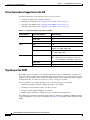
IGX Node Configuration 3-4
Naming a Node 3-5
Configuring the Time Zone 3-5
Configuring the Date and Time 3-5
Adding an Interface Shelf 3-6
Specifying Card Redundancy 3-6
Controlling External Devices 3-8
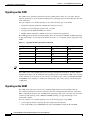
IGX Network Management 3-9
Optimizing Traffic Routing and Bandwidth
Specifying Channel Utilization 3-10
Specifying Class of Service 3-10
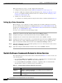
Routine Network Administration 3-14
Logging In to the System 3-14
Logging Off the System 3-14
Changing a Password 3-14
Synchronizing the Network 3-15
Managing Jobs 3-15
Creating (Adding) a Job 3-16
Running a Job 3-16
Stopping a Job 3-16
Displaying Jobs 3-17
Editing a Job 3-17
Deleting a Job 3-17
Creating a Job Trigger 3-17
Troubleshooting 3-18
Checking the AC Power Supplies 3-18
Troubleshooting an IGX Node 3-18
General Troubleshooting Procedures 3-19
Displaying a Summary of Alarms 3-19
Status of Cards 3-19
User-Initiated Tests 3-21
Loopback Tests 3-21
Card Testing with External Test Equipment
3-9
3-21
Cisco IGX 8400 Series Provisioning Guide, Release 9.3.3 and Later Releases
OL-1166-04
vii
Contents
Switch Software Commands Related to IGX Nodes
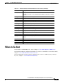
Where to Go Next
CHAPTER
4
3-22
3-23
Cisco IGX 8400 Series Trunks
4-1
Functional Overview 4-1
Virtual Trunking on the IGX 4-3
VPI, VCI, and Cell Header Formats 4-3
Virtual Trunks Supported on the IGX 4-5
IMA on the IGX 4-5
IMA Feeder Nodes in an IGX Network 4-5
IGX Trunk Configuration 4-6
Planning Bandwidth Usage 4-6
Planning for Cellbus Bandwidth Allocation 4-6
Bandwidth on IMA Trunks and Lines 4-8
Setting Up a Trunk 4-9
Setting Up a Virtual Trunk 4-9
Configuring a Virtual Trunk on the IGX 4-9
IGX Trunk Management 4-10
Event Logging 4-10
Reconfiguring a Trunk 4-10
Removing a Trunk 4-11
IGX Trunk Troubleshooting
Trunk Alarms 4-11
4-11
Switch Software Commands Related to IGX Trunks
Where to Go Next
CHAPTER
5
4-13
4-14
Cisco IGX 8400 Series Lines
5-1
Functional Overview 5-1
IMA on the IGX 5-1
IGX Line Configuration 5-3
Setting Up a Line 5-3
IGX Line Management
IGX Line Troubleshooting
5-3
5-3
Switch Software Commands Related to Lines on the IGX
Where to Go Next
5-3
5-4
Cisco IGX 8400 Series Provisioning Guide, Release 9.3.3 and Later Releases
viii
OL-1166-04
Contents
CHAPTER
6
Cisco IGX 8400 Series Data Service
6-1
Data Service—Functional Overview 6-1
Data Terminal Equipment and Data Circuit-Terminating Equipment
Data Service Connections Supported on the IGX 6-1
Data Service Provisioning 6-2
Setting Up a Data Connection 6-2
Configuring an Interface Control Template
Enabling DFM on a Data Channel 6-4
Enabling Embedded EIA on the LDM 6-4
6-3
Switch Software Command Related to Data Service
Where to Go Next
CHAPTER
7
6-1
6-5
6-5
Cisco IGX 8400 Series Voice Service
7-1
Voice Service—Functional Overview 7-1
Signaling 7-1
Switching 7-1
Voice Connections Supported on the IGX 7-2
Signaling on the UVM 7-2
D-Channel Compression on the UVM 7-3
Signaling on the CVM 7-4
Signaling on the URM 7-4
Idle-Code Suppression 7-5
Channel Pass-Through 7-5
Time-Division Multiplexing Transport 7-5
Voice Service Provisioning 7-5
Setting Up a Voice Connection
7-6
Switch Software Commands Related to Voice Service
Where to Go Next
CHAPTER
8
7-6
7-7
Cisco IGX 8400 Series ATM Service
8-1
ATM Service—Functional Overview 8-1
ATM Traffic Classes 8-1
Service Class Templates 8-2
Qbins 8-3
ATM Connections Supported on the IGX
UXM-E Connections 8-6
8-6
Cisco IGX 8400 Series Provisioning Guide, Release 9.3.3 and Later Releases
OL-1166-04
ix
Contents
ATM Service Provisioning on the IGX 8-7
Calculating and Managing Bandwidth 8-8
Setting Up an ATM Connection 8-8
Switch Software Commands Related to ATM Service
Where To Go Next
CHAPTER
8-10
Cisco IGX 8400 Series Frame Relay Service
9
8-9
9-1
Frame Relay—Functional Overview 9-1
Using Frame Relay Classes 9-2
Physical and Logical Frame Relay Ports 9-3
Frame Relay Connections Supported on the IGX 9-3
Frame Relay Provisioning 9-3
Setting Up FR Ports and Connections (UFM) 9-4
Commands for T1/E1 FR 9-5
Deleting a FR Port 9-5
Port Mode Selection for V.35 and X.21 9-5
Setting Up Frame Relay Ports and Connections (FRM)
9-6
Switch Software Commands Related to Frame Relay Connections
Where to Go Next
CHAPTER
10
9-7
9-8
Cisco IGX 8400 Series IP Service
10-1
IP Service—Functional Overview 10-1
Required Hardware and Software 10-1
URM 10-2
Virtual Slave Interfaces 10-3
VSI Masters and Slaves 10-3
Connection Admission Control 10-5
Service Class Templates 10-6
Qbins 10-14
MPLS Overview 10-18
MPLS Labeling Criteria 10-19
MPLS CoS on the IGX 10-20
MPLS-Enabled VPNs 10-23
MPLS Label Forwarding 10-31
Virtual Circuit Merge on the IGX 10-31
MPLS Connections Supported on the IGX
IP Service Provisioning 10-33
Planning for Controller Resources
10-32
10-34
Cisco IGX 8400 Series Provisioning Guide, Release 9.3.3 and Later Releases
x
OL-1166-04
Contents
VSI Configuration 10-34
Logical Switch Partitioning and Allocation of Resources 10-36
Slave Redundancy for the UXM and UXM-E 10-38
Adding and Deleting Controllers and Slaves 10-39
VC Merge on the IGX 10-40
Switch Software Commands Related to VSIs on the IGX 10-41
MPLS Configuration on the IGX 10-42
Initial Setup of LVCs 10-43
Configuring an IGX ATM-LSR for MPLS 10-44
Configuration for IGX Switch Portions of the Cisco IGX 8410, 8420, and 8430 ATM-LSRs 10-47
Configuration for LSC 1 and LSC 2 Portions of the Cisco IGX 8410, 8420, and 8430 10-51
Configuration for Edge Label Switch Routers, LSR-A and LSR-B 10-53
Routing Protocol Configures LVCs via MPLS 10-54
Testing the MPLS Network Configuration 10-55
Checking the IGX Extended ATM Interfaces 10-56
MPLS VPN Sample Configuration 10-59
Managing IP Services 10-67
Managing Slave Resources 10-67
Setting Up VSI Redundancy 10-68
Qbin Statistics 10-68
Summary of Qbin Statistics Commands
Where to Go Next
APPENDIX
A
10-69
Cisco IGX 8400 Series Feeder Nodes
About Tiered Networks
About Feeder Nodes
10-69
A-1
A-1
A-1
The IGX Feeder Node A-2
Enabling IGX Feeder Functionality A-3
Verifying IGX Feeder Functionality A-3
Disabling IGX Feeder Functionality A-3
Verifying That the IGX Feeder Functionality Is Disabled
Routing Nodes A-4
IGX Routing Node A-4
Inverse Multiplexing over ATM
BPX Routing Node A-5
MGX Routing Node A-5
See Also
A-3
A-4
A-5
INDEX
Cisco IGX 8400 Series Provisioning Guide, Release 9.3.3 and Later Releases
OL-1166-04
xi
Contents
Cisco IGX 8400 Series Provisioning Guide, Release 9.3.3 and Later Releases
xii
OL-1166-04
Preface
This preface discusses the objectives, audience, organization, and conventions found in the
Cisco IGX 8400 Series Provisioning Guide.
The Cisco IGX 8400 series (referred to as “IGX” in this guide) is a WAN switch platform running
Cisco WAN Switching System Software Release 9.3.30 or later releases (referred to as
“switch software” in this guide).
Objectives
This guide replaces previous Cisco IGX 8400 series platform documentation and is designed to be used
with multiple switch software releases. This guide has been optimized for online usage. If you are
accessing this guide through the Documentation CD-ROM, external links may not be accessible.
For information on initial installation and power-on, refer to the Cisco IGX 8400 Series Installation
Guide.
For detailed information on system configuration and troubleshooting commands, refer to the
Cisco WAN Switching Command Reference.
For more information on Cisco IOS configuration and troubleshooting commands, refer to the
appropriate Cisco IOS documentation set.
Audience
The Cisco IGX 8400 Series Provisioning Guide provides installers, operators, and network designers and
managers with the necessary understanding to plan for IGX usage in a network. This guide applies to the
Cisco IGX 8410, Cisco IGX 8420, and Cisco IGX 8430 in both rack-mount and standalone versions.
Cisco IGX 8400 Series Provisioning Guide, Release 9.3.3 and Later Releases
OL-1166-04
i
Preface
Organization
Organization
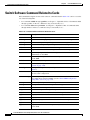
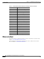
This document is organized into the following chapters:
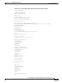
Table 1
Cisco IGX 8400 Series Provisioning Guide Organization
Chapter Number and Title
Chapter Description
Chapter 1, “Introduction to the Provides general networking and functional information on the
Cisco IGX 8400 Series”
Cisco IGX 8400 Series.
Chapter 2,
“Cisco IGX 8400 Series
Cards”
Provides information on IGX modules (front cards and back
cards).
Chapter 3, “Cisco IGX 8400
Series Nodes”
Provides information on IGX node setup and management.
Chapter 4, “Cisco IGX 8400
Series Trunks”
Provides information on IGX trunk setup and management.
Chapter 5, “Cisco IGX 8400
Series Lines”
Provides information on IGX line setup and management.
Chapter 6, “Cisco IGX 8400
Series Data Service”
Provides configuration and troubleshooting information specific
to IGX data services.
Chapter 7, “Cisco IGX 8400
Series Voice Service”
Provides configuration and troubleshooting information specific
to IGX voice services.
Chapter 8, “Cisco IGX 8400
Series ATM Service”
Provides configuration and troubleshooting information specific
to IGX ATM services.
Chapter 9, “Cisco IGX 8400
Series Frame Relay Service”
Provides configuration and troubleshooting information specific
to IGX Frame Relay services.
Chapter 10, “Cisco IGX 8400
Series IP Service”
Provides configuration and troubleshooting information specific
to IGX-URM MPLS services.
Appendix A, “Cisco IGX 8400 Provides information on using the IGX as a feeder node.
Series Feeder Nodes”
Tip
Some links in this online document connect with other Cisco documentation resources, such as
Cisco IOS documentation, or the Cisco WAN Switching Software Command Reference. When you find
the information you are looking for, use the back button on your web browser to return to this document.
Cisco IGX 8400 Series Provisioning Guide, Release 9.3.3 and Later Releases
ii
OL-1166-04
Preface
Document Conventions
Document Conventions
This publication uses the following conventions to convey instructions and information.
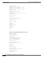
Table 2
Note
Timesaver
Caution
Tip
Document Conventions
Convention
Description
boldface font
Commands and keywords.
italic font
Variables for which you supply values.
[
Keywords or arguments that appear within square brackets are optional.
]
{x | y | z}
A choice of required keywords appears in braces separated by vertical bars.
You must select one.
screen font
Examples of information displayed on the screen.
boldface screen
font
Examples of information you must enter.
<
>
Nonprinting characters, for example passwords, appear in angle brackets in
contexts where italic font is not available.
[
]
Default responses to system prompts appear in square brackets.
This symbol means reader take note. Notes contain helpful suggestions or references to additional
information and material.
This symbol means the described action saves time. You can save time by performing the action
described in the paragraph.
This symbol means reader be careful. In this situation, you might do something that could result in
equipment damage or loss of data.
This symbol means the following information will help you solve a problem. The tips information might
not be troubleshooting or even an action, but could be useful information, similar to a Timesaver.
Cisco IGX 8400 Series Provisioning Guide, Release 9.3.3 and Later Releases
OL-1166-04
iii
Preface
Document Conventions
Warning
IMPORTANT SAFETY INSTRUCTIONS
This warning symbol means danger. You are in a situation that could cause bodily injury. Before you
work on any equipment, be aware of the hazards involved with electrical circuitry and be familiar
with standard practices for preventing accidents. To see translations of the warnings that appear in
this publication, refer to the translated safety warnings that accompanied this device.
Note: SAVE THESE INSTRUCTIONS
Note: This documentation is to be used in conjunction with the specific product installation guide
that shipped with the product. Please refer to the Installation Guide, Configuration Guide, or other
enclosed additional documentation for further details.
Waarschuwing
BELANGRIJKE VEILIGHEIDSINSTRUCTIES
Dit waarschuwingssymbool betekent gevaar. U verkeert in een situatie die lichamelijk letsel kan
veroorzaken. Voordat u aan enige apparatuur gaat werken, dient u zich bewust te zijn van de bij
elektrische schakelingen betrokken risico's en dient u op de hoogte te zijn van de standaard
praktijken om ongelukken te voorkomen. Voor een vertaling van de waarschuwingen die in deze
publicatie verschijnen, dient u de vertaalde veiligheidswaarschuwingen te raadplegen die bij dit
apparaat worden geleverd.
Opmerking BEWAAR DEZE INSTRUCTIES.
Opmerking Deze documentatie dient gebruikt te worden in combinatie met de
installatiehandleiding voor het specifieke product die bij het product wordt geleverd. Raadpleeg de
installatiehandleiding, configuratiehandleiding of andere verdere ingesloten documentatie voor
meer informatie.
Varoitus
TÄRKEITÄ TURVALLISUUTEEN LIITTYVIÄ OHJEITA
Tämä varoitusmerkki merkitsee vaaraa. Olet tilanteessa, joka voi johtaa ruumiinvammaan. Ennen
kuin työskentelet minkään laitteiston parissa, ota selvää sähkökytkentöihin liittyvistä vaaroista ja
tavanomaisista onnettomuuksien ehkäisykeinoista. Tässä asiakirjassa esitettyjen varoitusten
käännökset löydät laitteen mukana toimitetuista ohjeista.
Huomautus SÄILYTÄ NÄMÄ OHJEET
Huomautus Tämä asiakirja on tarkoitettu käytettäväksi yhdessä tuotteen mukana tulleen
asennusoppaan kanssa. Katso lisätietoja asennusoppaasta, kokoonpano-oppaasta ja muista
mukana toimitetuista asiakirjoista.
Cisco IGX 8400 Series Provisioning Guide, Release 9.3.3 and Later Releases
iv
OL-1166-04
Preface
Document Conventions
Attention
IMPORTANTES INFORMATIONS DE SÉCURITÉ
Ce symbole d'avertissement indique un danger. Vous vous trouvez dans une situation pouvant causer
des blessures ou des dommages corporels. Avant de travailler sur un équipement, soyez conscient
des dangers posés par les circuits électriques et familiarisez-vous avec les procédures couramment
utilisées pour éviter les accidents. Pour prendre connaissance des traductions d'avertissements
figurant dans cette publication, consultez les consignes de sécurité traduites qui accompagnent cet
appareil.
Remarque CONSERVEZ CES INFORMATIONS
Remarque Cette documentation doit être utilisée avec le guide spécifique d'installation du produit
qui accompagne ce dernier. Veuillez vous reporter au Guide d'installation, au Guide de
configuration, ou à toute autre documentation jointe pour de plus amples renseignements.
Warnung
WICHTIGE SICHERHEITSANWEISUNGEN
Dieses Warnsymbol bedeutet Gefahr. Sie befinden sich in einer Situation, die zu einer
Körperverletzung führen könnte. Bevor Sie mit der Arbeit an irgendeinem Gerät beginnen, seien Sie
sich der mit elektrischen Stromkreisen verbundenen Gefahren und der Standardpraktiken zur
Vermeidung von Unfällen bewusst. Übersetzungen der in dieser Veröffentlichung enthaltenen
Warnhinweise sind im Lieferumfang des Geräts enthalten.
Hinweis BEWAHREN SIE DIESE SICHERHEITSANWEISUNGEN AUF
Hinweis Dieses Handbuch ist zum Gebrauch in Verbindung mit dem Installationshandbuch für Ihr
Gerät bestimmt, das dem Gerät beiliegt. Entnehmen Sie bitte alle weiteren Informationen dem
Handbuch (Installations- oder Konfigurationshandbuch o. Ä.) für Ihr spezifisches Gerät.
Figyelem!
FONTOS BIZTONSÁGI ELÕÍRÁSOK
Ez a figyelmezetõ jel veszélyre utal. Sérülésveszélyt rejtõ helyzetben van. Mielõtt bármely
berendezésen munkát végezte, legyen figyelemmel az elektromos áramkörök okozta kockázatokra,
és ismerkedjen meg a szokásos balesetvédelmi eljárásokkal. A kiadványban szereplõ
figyelmeztetések fordítása a készülékhez mellékelt biztonsági figyelmeztetések között található.
Megjegyzés ÕRIZZE MEG EZEKET AZ UTASÍTÁSOKAT!
Megjegyzés Ezt a dokumentációt a készülékhez mellékelt üzembe helyezési útmutatóval együtt kell
használni. További tudnivalók a mellékelt Üzembe helyezési útmutatóban (Installation Guide),
Konfigurációs útmutatóban (Configuration Guide) vagy más dokumentumban találhatók.
Avvertenza
IMPORTANTI ISTRUZIONI SULLA SICUREZZA
Questo simbolo di avvertenza indica un pericolo. La situazione potrebbe causare infortuni alle
persone. Prima di intervenire su qualsiasi apparecchiatura, occorre essere al corrente dei pericoli
relativi ai circuiti elettrici e conoscere le procedure standard per la prevenzione di incidenti. Per le
traduzioni delle avvertenze riportate in questo documento, vedere le avvertenze di sicurezza che
accompagnano questo dispositivo.
Nota CONSERVARE QUESTE ISTRUZIONI
Nota La presente documentazione va usata congiuntamente alla guida di installazione specifica
spedita con il prodotto. Per maggiori informazioni, consultare la Guida all'installazione, la Guida
alla configurazione o altra documentazione acclusa.
Cisco IGX 8400 Series Provisioning Guide, Release 9.3.3 and Later Releases
OL-1166-04
v
Preface
Document Conventions
Advarsel
VIKTIGE SIKKERHETSINSTRUKSJONER
Dette varselssymbolet betyr fare. Du befinner deg i en situasjon som kan forårsake personskade.
Før du utfører arbeid med utstyret, bør du være oppmerksom på farene som er forbundet med
elektriske kretssystemer, og du bør være kjent med vanlig praksis for å unngå ulykker. For å se
oversettelser av advarslene i denne publikasjonen, se de oversatte sikkerhetsvarslene som følger
med denne enheten.
Merk TA VARE PÅ DISSE INSTRUKSJONENE
Merk Denne dokumentasjonen skal brukes i forbindelse med den spesifikke
installasjonsveiledningen som fulgte med produktet. Vennligst se installasjonsveiledningen,
konfigureringsveiledningen eller annen vedlagt tilleggsdokumentasjon for detaljer.
Aviso
INSTRUÇÕES IMPORTANTES DE SEGURANÇA
Este símbolo de aviso significa perigo. O utilizador encontra-se numa situação que poderá ser
causadora de lesões corporais. Antes de iniciar a utilização de qualquer equipamento, tenha em
atenção os perigos envolvidos no manuseamento de circuitos eléctricos e familiarize-se com as
práticas habituais de prevenção de acidentes. Para ver traduções dos avisos incluídos nesta
publicação, consulte os avisos de segurança traduzidos que acompanham este dispositivo.
Nota GUARDE ESTAS INSTRUÇÕES
Nota Esta documentação destina-se a ser utilizada em conjunto com o manual de instalação
incluído com o produto específico. Consulte o manual de instalação, o manual de configuração ou
outra documentação adicional inclusa, para obter mais informações.
¡Advertencia!
INSTRUCCIONES IMPORTANTES DE SEGURIDAD
Este símbolo de aviso indica peligro. Existe riesgo para su integridad física. Antes de manipular
cualquier equipo, considere los riesgos de la corriente eléctrica y familiarícese con los
procedimientos estándar de prevención de accidentes. Vea las traducciones de las advertencias
que acompañan a este dispositivo.
Nota GUARDE ESTAS INSTRUCCIONES
Nota Esta documentación está pensada para ser utilizada con la guía de instalación del producto
que lo acompaña. Si necesita más detalles, consulte la Guía de instalación, la Guía de
configuración o cualquier documentación adicional adjunta.
Varning!
VIKTIGA SÄKERHETSANVISNINGAR
Denna varningssignal signalerar fara. Du befinner dig i en situation som kan leda till personskada.
Innan du utför arbete på någon utrustning måste du vara medveten om farorna med elkretsar och
känna till vanliga förfaranden för att förebygga olyckor. Se översättningarna av de
varningsmeddelanden som finns i denna publikation, och se de översatta säkerhetsvarningarna som
medföljer denna anordning.
OBS! SPARA DESSA ANVISNINGAR
OBS! Denna dokumentation ska användas i samband med den specifika
produktinstallationshandbok som medföljde produkten. Se installationshandboken,
konfigurationshandboken eller annan bifogad ytterligare dokumentation för närmare detaljer.
Cisco IGX 8400 Series Provisioning Guide, Release 9.3.3 and Later Releases
vi
OL-1166-04
Preface
New or Changed Information
New or Changed Information
This section describes updates to this publication.
Switch Software Release 9.3.40
The following sections have been added or updated to support Switch Software Release 9.3.40:
•
“Y-Redundancy and VC Merge on the UXM-E” section on page 2-34, in Chapter 2, “Functional
Overview.”
•
“Virtual Circuit Merge on the IGX” section on page 10-31 and the “VC Merge on the IGX” section
on page 10-40 in Chapter 10, “IP Service—Functional Overview.”
Cisco IGX 8400 Series Provisioning Guide, Release 9.3.3 and Later Releases
OL-1166-04
vii
Preface
Related Documentation
Switch Software Release 9.4.00
The following content has been added to support Switch Software Release 9.4.00:
•
“URM Cisco IOS CLI Access—Switch Software Release 9.3.x and Earlier Releases” section on
page 99 in Chapter 2, “Cisco IGX 8400 Series Cards”
•
“URM Cisco IOS CLI Access—Switch Software Release 9.4.0 and Later Releases” section on
page 99 in Chapter 2, “Cisco IGX 8400 Series Cards”
•
Appendix A, “Cisco IGX 8400 Series Feeder Nodes”
Related Documentation
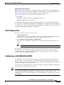
Tip
The universal router module (URM) is a dual-processor card, featuring both a modified
Cisco IGX 8400 series UXM-E processor and a modified Cisco 3660 modular-access router processor.
Each processor uses a different operating system; refer to documentation for both Cisco IOS software
and switch software while working with the URM.
All related technical documentation is available online and on the Documentation CD-ROM. You can
also order some printed documentation using the document number. See the “Accessing User
Documentation” section on page xii and the “Obtaining Documentation” section on page xiii for more
information.
Cisco IGX 8400 Series Documentation
Cisco IGX 8400 series product documentation provides information regarding hardware installation,
cabling, basic configuration, and regulatory compliance and safety information. Documentation in this
category includes the following:
Note
•
Cisco IGX 8400 Series Installation Guide
•
Cisco IGX 8400 Series Provisioning Guide (this guide)
•
Cisco IGX 8400 Series Regulatory Compliance and Safety Information
Cisco IGX 8400 series documentation is organized under the switch software release number. If you
have multiple releases in your network, refer to the latest release for the most current IGX
documentation.
You can access these documents at Cisco Product Documentation > WAN Switches >
IGX 8400 Series.
Or use the following links:
•
Cisco IGX 8400 Series Installation Guide
•
Cisco IGX 8400 Series Provisioning Guide (this guide)
•
Cisco IGX 8400 Series Regulatory Compliance and Safety Information
Cisco IGX 8400 Series Provisioning Guide, Release 9.3.3 and Later Releases
viii
OL-1166-04
Preface
Related Documentation
Cisco WAN Switching System Software and Related Hardware Documentation
Cisco WAN Switching System Software Documentation
Cisco WAN Switching System Software (switch software) product documentation provides additional
information on the switch software commands used to configure the IGX. Documentation in this
category includes the following:
•
Cisco WAN Switching Command Reference (Release 8.2 to Release 9.3.30).
•
Cisco WAN Switching SuperUser Command Reference (Release 8.2 to Release 9.3.10).
•
9.3.40 Version Software Release Notes Cisco WAN Switching System Software (Release 9.3.40).
You can access these documents at Cisco Product Documentation > WAN Switches > IGX 8400 >
switch software release number.
Related Hardware Documentation
The following documents describe hardware often used in conjunction with the IGX:
•
Cisco WAN Interface Cards Hardware Installation Guide
•
Cisco BPX 8600 Series Installation and Configuration, Release 9.3.30
You can access the Cisco WAN Interface Cards Hardware Installation Guide at Cisco Product
Documentation > Access Servers & Routers > Modular Access Routers > Cisco 3600 Series
Routers > Hardware installation documents for Cisco 3600 series > WAN interface card (WIC)
installation.
You can access the Cisco BPX 8600 Series Installation and Configuration publication at Cisco Product
Documentation > WAN Switches > BPX 8600 Series > switch software release number.
Cisco IOS Software Documentation
Note
Cisco IOS software is available only on the universal router module (URM) front card. Unless you
intend to configure the IGX for IP services using the URM, you do not need to refer to
Cisco IOS documentation.
Cisco IOS software documentation provides information on using the Cisco IOS software required by
the IGX for IP services.
Note
Cisco IOS documentation is organized by Cisco IOS release, then by product type and name.
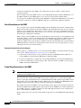
Determining Platform Support Through Feature Navigator
Cisco IOS software is packaged in feature sets that support specific platforms. To get updated
information regarding platform support for this feature, access Feature Navigator. Feature Navigator
dynamically updates the list of supported platforms as new platform support is added for the feature.
Feature Navigator is a web-based tool that enables you to quickly determine which Cisco IOS software
images support a specific set of features and which features are supported in a specific Cisco IOS image.
Cisco IGX 8400 Series Provisioning Guide, Release 9.3.3 and Later Releases
OL-1166-04
ix
Preface
Related Documentation
To access Feature Navigator, you must have an account on Cisco.com. If you have forgotten or lost your
account information, send a blank e-mail to [email protected]. An automatic check will verify
that your e-mail address is registered with Cisco.com. If the check is successful, account details with a
new random password will be e-mailed to you. Qualified users can establish an account on Cisco.com
by following the directions at http://www.cisco.com/register.
Feature Navigator is updated regularly when major Cisco IOS software releases and technology releases
occur. For the most current information, go to the Feature Navigator home page at the following URL:
http://www.cisco.com/go/fn
Main Cisco IOS Software Documentation Pages by Release
The main Cisco IOS software documentation pages provide links to all software documentation
available for the release. Cisco IOS software documentation is classified as outlined in the following
sections.
You can access the main Cisco IOS software documentation pages at Cisco Product Documentation >
Cisco IOS Software > Cisco IOS Software Release you are using.
Or use the following links:
•
Cisco IOS Release 12.1
•
Cisco IOS Release 12.2
Master Index to Software Documentation
The Cisco IOS software documentation provides detailed configuration procedures and examples.
You can access these documents at Cisco Product Documentation > Cisco IOS Software > Cisco IOS
Software Release you are using > Cisco IOS Release x.x Master Index> Configuration guide or
command reference indexes.
Or use the following links:
•
Cisco IOS Release 12.1 Master Indexes
•
Cisco IOS Release 12.2 Master Indexes
Configuration Guides
The Cisco IOS software configuration guides provide detailed configuration procedures and examples.
You can access these documents at Cisco Product Documentation > Cisco IOS Software > Cisco IOS
Software Release you are using > Configuration Guides and Command References > Configuration
guide for your application.
Or use the following links:
•
Cisco IOS Configuration Guides and Command References, Release 12.1
•
Cisco IOS Configuration Guides and Command References, Release 12.2
•
Cisco IOS Configuration Fundamentals Configuration Guide, Release 12.1
•
Cisco IOS Configuration Fundamentals Configuration Guide, Release 12.2
•
Cisco IOS Wide-Area Networking Configuration Guide, Release 12.1
•
Cisco IOS Wide-Area Networking Configuration Guide, Release 12.2
Cisco IGX 8400 Series Provisioning Guide, Release 9.3.3 and Later Releases
x
OL-1166-04
Preface
Related Documentation
Command References
The Cisco IOS software command references provide detailed information about each configuration
command.
You can access these documents at Cisco Product Documentation > Cisco IOS Software > Cisco IOS
Software Release you are using > Configuration Guides and Command References > Command
reference for your application.
Or use the following links:
•
Cisco IOS Configuration Guides and Command References, Release 12.1
•
Cisco IOS Configuration Guides and Command References, Release 12.2
•
Cisco IOS Configuration Fundamentals Command Reference, Release 12.1
•
Cisco IOS Configuration Fundamentals Command Reference, Release 12.2
•
Cisco IOS Wide-Area Networking Command Reference, Release 12.1
•
Cisco IOS Wide-Area Networking Command Reference, Release 12.2
New Feature Documentation
New Feature Documentation contains detailed information about new configuration commands
introduced in specific Cisco IOS releases.
You can access these documents at Cisco Product Documentation > Cisco IOS Software > Cisco IOS
Software Release you are using > New Feature Documentation > New Features for the Cisco IOS
Software Release you are using.
Or use the following links:
•
Cisco IOS New Feature Documentation, Release 12.1
•
Cisco IOS New Feature Documentation, Release 12.2
•
Cisco IOS Voice Features on IGX 8400 Series Universal Router Module
•
MPLS Label Switch Controller and Enhancements 12.2(8)T.
Release Notes
Cisco IOS release notes for all platforms provide up-to-date information about specific Cisco IOS
software releases.
You can access these documents at Cisco Product Documentation > Cisco IOS Software
Configuration > Cisco IOS Software Release you are using > Release Notes > Release Notes for the
Cisco IOS Software Release you are using.
Or use the following links:
•
Release Notes for Cisco IGX 8400 Series URM for Cisco IOS Release 12.1 YA
•
Cisco IOS Release Notes, Release 12.1
•
Cisco IOS Release Notes, Release 12.2
Supporting Documents and Related Documentation
Additional documentation provides information about specific Cisco IOS software releases, platforms,
and applications, and other supporting documentation.
Cisco IGX 8400 Series Provisioning Guide, Release 9.3.3 and Later Releases
OL-1166-04
xi
Preface
Accessing User Documentation
You can access these documents at Cisco Product Documentation > Cisco IOS Software
Configuration > Cisco IOS Software Release you are using > Supporting Documents or Related
Documentation.
Or use the following links:
•
Cisco IOS Supporting Documents, Release 12.1
•
Cisco IOS Supporting Documents, Release 12.2
•
Cisco IOS Related Documents, Release 12.1
•
Cisco IOS Related Documents, Release 12.2
Accessing User Documentation
The following sections provide information on accessing user documentation online or through the
included Documentation CD-ROM.
Accessing Online User Documentation
To access online user documentation, you need a desktop or notebook computer with an installed
graphical Internet browser and an active connection to the Internet. If you do not have an active Internet
connection available, use the Documentation CD-ROM included with this letter to access the product’s
user documentation (see the “Accessing User Documentation on the Documentation CD-ROM” section
on page xii).
Step 1
Open your Internet browser.
Step 2
Log in to Cisco.com at http://www.cisco.com.
Note
If you do not have a user account, click Register in the navigational bar at the top of the page
and proceed through the registration process.
Step 3
Select Technical Documentation under the Service & Support heading.
Step 4
Select Cisco Product Documentation to open the Cisco Product Documentation index.
Step 5
Use the document paths provided in the “Related Documentation” section on page viii to find the
specific document you need.
Accessing User Documentation on the Documentation CD-ROM
To access user documentation on the CD-ROM, you need a desktop or notebook computer with an
installed graphical Internet browser and a CD-ROM drive.
Timesaver
Follow the Documentation CD-ROM installation instructions found in the CD package before
attempting to access user documentation. CD-ROM installation takes approximately 5-10 minutes,
depending on your computer and your installation requirements.
Cisco IGX 8400 Series Provisioning Guide, Release 9.3.3 and Later Releases
xii
OL-1166-04
Preface
Obtaining Documentation
Step 1
Insert the Documentation CD (disc 2) into your CD-ROM drive and launch the Documentation CD
(CiscoCD).
Step 2
Select Cisco Product Documentation to open the Cisco Product Documentation index.
Step 3
Use the document paths provided in the “Related Documentation” section on page viii to find the
specific document you need.
Obtaining Documentation
Cisco provides several ways to obtain documentation, technical assistance, and other technical
resources. These sections explain how to obtain technical information from Cisco Systems.
Cisco.com
You can access the most current Cisco documentation on the World Wide Web at this URL:
http://www.cisco.com/univercd/home/home.htm
You can access the Cisco website at this URL:
http://www.cisco.com
International Cisco websites can be accessed from this URL:
http://www.cisco.com/public/countries_languages.shtml
Documentation CD-ROM
Cisco documentation and additional literature are available in a Cisco Documentation CD-ROM
package, which may have shipped with your product. The Documentation CD-ROM is updated regularly
and may be more current than printed documentation. The CD-ROM package is available as a single unit
or through an annual or quarterly subscription.
Registered Cisco.com users can order a single Documentation CD-ROM (product number
DOC-CONDOCCD=) through the Cisco Ordering tool:
http://www.cisco.com/en/US/partner/ordering/ordering_place_order_ordering_tool_launch.html
All users can order monthly or quarterly subscriptions through the online Subscription Store:
http://www.cisco.com/go/subscription
Ordering Documentation
You can find instructions for ordering documentation at this URL:
http://www.cisco.com/univercd/cc/td/doc/es_inpck/pdi.htm
Cisco IGX 8400 Series Provisioning Guide, Release 9.3.3 and Later Releases
OL-1166-04
xiii
Preface
Obtaining Technical Assistance
You can order Cisco documentation in these ways:
•
Registered Cisco.com users (Cisco direct customers) can order Cisco product documentation from
the Networking Products MarketPlace:
http://www.cisco.com/en/US/partner/ordering/index.shtml
•
Nonregistered Cisco.com users can order documentation through a local account representative by
calling Cisco Systems Corporate Headquarters (California, U.S.A.) at 408 526-7208 or, elsewhere
in North America, by calling 800 553-NETS (6387).
Documentation Feedback
You can submit comments electronically on Cisco.com. On the Cisco Documentation home page, click
Feedback at the top of the page.
You can e-mail your comments to [email protected].
You can submit comments by using the response card (if present) behind the front cover of your
document or by writing to the following address:
Cisco Systems
Attn: Customer Document Ordering
170 West Tasman Drive
San Jose, CA 95134-9883
We appreciate your comments.
Obtaining Technical Assistance
Cisco provides Cisco.com, which includes the Cisco Technical Assistance Center (TAC) website, as a
starting point for all technical assistance. Customers and partners can obtain online documentation,
troubleshooting tips, and sample configurations from the Cisco TAC website. Cisco.com registered
users have complete access to the technical support resources on the Cisco TAC website, including TAC
tools and utilities.
Cisco.com
Cisco.com offers a suite of interactive, networked services that let you access Cisco information,
networking solutions, services, programs, and resources at any time, from anywhere in the world.
Cisco.com provides a broad range of features and services to help you with these tasks:
•
Streamline business processes and improve productivity
•
Resolve technical issues with online support
•
Download and test software packages
•
Order Cisco learning materials and merchandise
•
Register for online skill assessment, training, and certification programs
To obtain customized information and service, you can self-register on Cisco.com at this URL:
http://tools.cisco.com/RPF/register/register.do
Cisco IGX 8400 Series Provisioning Guide, Release 9.3.3 and Later Releases
xiv
OL-1166-04
Preface
Obtaining Technical Assistance
Technical Assistance Center
The Cisco TAC is available to all customers who need technical assistance with a Cisco product,
technology, or solution. Two types of support are available: the Cisco TAC website and the Cisco TAC
Escalation Center. The type of support that you choose depends on the priority of the problem and the
conditions stated in service contracts, when applicable.
We categorize Cisco TAC inquiries according to urgency:
•
Priority level 4 (P4)—You need information or assistance concerning Cisco product capabilities,
product installation, or basic product configuration. There is little or no impact to your business
operations.
•
Priority level 3 (P3)—Operational performance of the network is impaired, but most business
operations remain functional. You and Cisco are willing to commit resources during normal
business hours to restore service to satisfactory levels.
•
Priority level 2 (P2)—Operation of an existing network is severely degraded, or significant aspects
of your business operations are negatively impacted by inadequate performance of Cisco products.
You and Cisco will commit full-time resources during normal business hours to resolve the
situation.
•
Priority level 1 (P1)—An existing network is “down,” or there is a critical impact to your business
operations. You and Cisco will commit all necessary resources around the clock to resolve the
situation.
Cisco TAC Website
The Cisco TAC website provides online documents and tools to help troubleshoot and resolve technical
issues with Cisco products and technologies. To access the Cisco TAC website, go to this URL:
http://www.cisco.com/tac
All customers, partners, and resellers who have a valid Cisco service contract have complete access to
the technical support resources on the Cisco TAC website. Some services on the Cisco TAC website
require a Cisco.com login ID and password. If you have a valid service contract but do not have a login
ID or password, go to this URL to register:
http://tools.cisco.com/RPF/register/register.do
If you are a Cisco.com registered user, and you cannot resolve your technical issues by using the Cisco
TAC website, you can open a case online at this URL:
http://www.cisco.com/tac/caseopen
If you have Internet access, we recommend that you open P3 and P4 cases online so that you can fully
describe the situation and attach any necessary files.
Cisco TAC Escalation Center
The Cisco TAC Escalation Center addresses priority level 1 or priority level 2 issues. These
classifications are assigned when severe network degradation significantly impacts business operations.
When you contact the TAC Escalation Center with a P1 or P2 problem, a Cisco TAC engineer
automatically opens a case.
To obtain a directory of toll-free Cisco TAC telephone numbers for your country, go to this URL:
http://www.cisco.com/warp/public/687/Directory/DirTAC.shtml
Cisco IGX 8400 Series Provisioning Guide, Release 9.3.3 and Later Releases
OL-1166-04
xv
Preface
Obtaining Additional Publications and Information
Before calling, please check with your network operations center to determine the Cisco support services
to which your company is entitled: for example, SMARTnet, SMARTnet Onsite, or Network Supported
Accounts (NSA). When you call the center, please have available your service agreement number and
your product serial number.
Obtaining Additional Publications and Information
Information about Cisco products, technologies, and network solutions is available from various online
and printed sources.
•
The Cisco Product Catalog describes the networking products offered by Cisco Systems, as well as
ordering and customer support services. Access the Cisco Product Catalog at this URL:
http://www.cisco.com/en/US/products/products_catalog_links_launch.html
•
Cisco Press publishes a wide range of networking publications. Cisco suggests these titles for new
and experienced users: Internetworking Terms and Acronyms Dictionary, Internetworking
Technology Handbook, Internetworking Troubleshooting Guide, and the Internetworking Design
Guide. For current Cisco Press titles and other information, go to Cisco Press online at this URL:
http://www.ciscopress.com
•
Packet magazine is the Cisco quarterly publication that provides the latest networking trends,
technology breakthroughs, and Cisco products and solutions to help industry professionals get the
most from their networking investment. Included are networking deployment and troubleshooting
tips, configuration examples, customer case studies, tutorials and training, certification information,
and links to numerous in-depth online resources. You can access Packet magazine at this URL:
http://www.cisco.com/go/packet
•
iQ Magazine is the Cisco bimonthly publication that delivers the latest information about Internet
business strategies for executives. You can access iQ Magazine at this URL:
http://www.cisco.com/go/iqmagazine
•
Internet Protocol Journal is a quarterly journal published by Cisco Systems for engineering
professionals involved in designing, developing, and operating public and private internets and
intranets. You can access the Internet Protocol Journal at this URL:
http://www.cisco.com/en/US/about/ac123/ac147/about_cisco_the_internet_protocol_journal.html
•
Training—Cisco offers world-class networking training. Current offerings in network training are
listed at this URL:
http://www.cisco.com/en/US/learning/le31/learning_recommended_training_list.html
Where to Go Next
For an introduction to the Cisco IGX 8400 series, see Chapter 1, “Introduction to the Cisco IGX 8400
Series.”
For installation and basic configuration information, see the Cisco IGX 8400 Series Installation Guide.
For more information on switch software commands, refer to the Cisco WAN Switching Command
Reference, Chapter 1, “Command Line Fundamentals.”
Cisco IGX 8400 Series Provisioning Guide, Release 9.3.3 and Later Releases
xvi
OL-1166-04
C H A P T E R
1
Introduction to the Cisco IGX 8400 Series
This guide describes the IGX hardware that runs Release 9.3.30 or later of the Cisco WAN Switching
System Software (switch software) and provides instructions for provisioning services across networks
containing an IGX node. The descriptions cover both common and unique aspects of the
Cisco IGX 8410, 8420, and 8430 models.
For a description of how to install and start an IGX switch, refer to the Cisco IGX 8400 Series
Installation Guide.
For information about the BPX, see Chapter 1, “The BPX Switch: Functional Overview,” in the
Cisco BPX 8600 Series Installation and Configuration guide.
Features of the IGX 8400 Series
Like other Cisco switches, the IGX node operates in public or private wide-area networks (WANs). An
IGX node can support OC3, T3, E3, T1, E1, ATM standards-based inverse multiplexing (also known as
IMA) for T1 or E1, fractional T1 or E1, or subrate digital transmission facilities. The IGX cell relay
technology provides maximum throughput with minimum delays. Cell relay performance characteristics
are the heart of efficient digital networks and make the IGX node an ideal choice for a high-performance,
multimedia platform. Key features of the IGX switch include:
•
A 1 gigabit per second (Gbps) cellbus for high-speed switching and a redundant 0.2 Gbps bus for
backup.
•
Full compatibility with Cisco BPX 8600 series system software.
•
Up to 64 lines, 32 trunks, and 3500 connections on the Cisco IGX 8420 and Cisco IGX 8430
models.
•
IGX configuration and management through Cisco WAN Manager or the switch software
command-line interface (CLI).
•
High performance switching suitable for a variety of protocols/applications, including
Asynchronous Transfer Mode (ATM), Frame Relay (FR), voice, fax, slow-scan and full-bandwidth
video, and synchronous or asynchronous data.
•
Six cabinet models, which consist of:
– An 8-slot standalone unit
– An 8-slot rack-mount unit
– A 16-slot standalone unit
– A 16-slot rack-mount unit
Cisco IGX 8400 Series Provisioning Guide, Release 9.3.3 and Later Releases
OL-1166-04
1-1
Chapter 1
Introduction to the Cisco IGX 8400 Series
Where To Go Next
– A 32-slot standalone unit
– A 32-slot rack-mount unit
•
Redundancy of controller cards, service module cards, system buses, and power supplies to provide
hardware reliability.
•
Hot-swappable modules to facilitate non-stop operation: service cards, NPMs, AC power supplies,
and fan tray assembly.
•
110/220 VAC and -48 DC power options for use in varied network environments.
Where To Go Next
For information on cards supported on the IGX, refer to Chapter 2, “Cisco IGX 8400 Series Cards”
For installation and basic configuration information, see the Cisco IGX 8400 Series Installation Guide.
For more information on switch software commands, refer to the Cisco WAN Switching Command
Reference, Chapter 1, “Command Line Fundamentals.”
Cisco IGX 8400 Series Provisioning Guide, Release 9.3.3 and Later Releases
1-2
OL-1166-04
C H A P T E R
2
Cisco IGX 8400 Series Cards
This chapter provides a description of the cards available for use in the IGX node. Some of the cards
described in this manual may no longer be available for purchase, so please check with your account
representative for card availability.
Most cards use the standard installation and initial configuration procedures described in “Installing the
IGX” This chapter details exceptions and recommendations specific to each card.
Note
The following cards are not supported in switch software Release 9.3 or later: FTM and back cards, BTM
and back cards, ALM/A and back cards, and ALM/B and back cards. For information on these cards,
refer to IGX documentation from earlier switch software releases.
For information about the BPX, see Chapter 1, “The BPX Switch: Functional Overview,” in the
Cisco BPX 8600 Series Installation and Configuration manual.
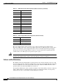
Functional Overview
The Cisco IGX 8400 Series WAN switch uses combinations of front cards and back cards (or modules)
to provide the user with greater configurational adaptability and flexibility. These modules can be
classified into functional types as follows:
•
Processor cards, which contain the system controller that runs software for the switch,
•
Alarm cards, which provides alarm decoding and alarm summary outputs, and
•
Service cards, which allow for various information-handling services.
Processor cards are necessary for node function. Without a processor card, the switch has no software
and cannot continue with power-on.
Alarm cards are optional, and are recommended because they provide alarm summary information as an
aid in troubleshooting node and network problems.
Service cards provide a wide variety of information-handling services, including the following:
•
Data (see Chapter 6, “Cisco IGX 8400 Series Data Service”)
•
Voice (see Chapter 7, “Cisco IGX 8400 Series Voice Service”)
•
ATM (see Chapter 8, “Cisco IGX 8400 Series ATM Service”)
•
Frame Relay (see Chapter 9, “Cisco IGX 8400 Series Frame Relay Service”)
Cisco IGX 8400 Series Provisioning Guide, Release 9.3.3 and Later Releases
OL-1166-04
2-1
Chapter 2
Cisco IGX 8400 Series Cards
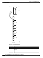
Nodal Processor Module
Nodal Processor Module
The IGX nodal processor module (NPM) group consists of a front card (called NPM) and a system clock
module (SCM) back card.
The NPM performs the following major functions:
•
Runs the software for controlling, configuring, diagnosing, and monitoring the IGX switch.
•
Sends configuration and control commands over the control bus to other cards in the switch.
•
Receives statistics, status, and alarm messages from the other cards in the switch.
•
Generates all system bus control signals for directing the interpretation of address buses and
controlling data transfers.
•
Communicates with other nodes and network management devices in the network.
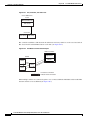
The NPM has a 68040 microprocessor-based system controller running switch software for the IGX
chassis and communicates with other IGX cards over the control bus. In conjunction with the system
bus, the NPM is responsible for system timing, network control, and status reporting.
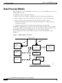
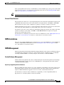
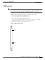
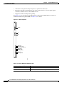
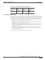
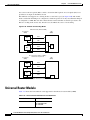
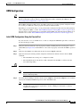
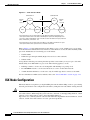
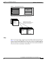
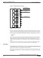
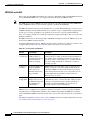
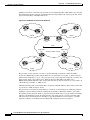
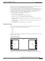
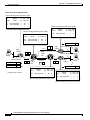
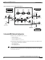
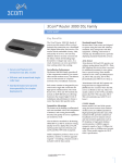
Figure 2-1 illustrates the relation of the NPM to other parts of the system (including attached
peripherals).
Figure 2-1
NPM in Relation to the System
Corporate network
AUI
AUI
Cisco
WAN Manager
*
*
Modem
Ext clock
Ext monitor
SCM
Utility bus
Redundant
NPM
Printer
H8313
NPM
Cisco IGX 8400 Series Provisioning Guide, Release 9.3.3 and Later Releases
2-2
OL-1166-04
Chapter 2
Cisco IGX 8400 Series Cards
Nodal Processor Module
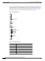
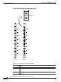
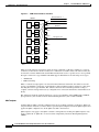
NPM Front Card
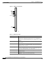
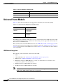
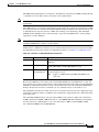
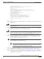
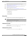
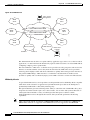
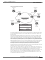
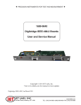
The NPM front card monitors its own activity. When a failure is detected, the fail LED is lit. In nodes
with redundant NPMs, the active NPM is indicated by an active LED, while the standby NPM will not
have a lit active LED (see Figure 2-2). To display information on any NPM from the switch software
command-line interface (CLI), use the switch software dspcd command.
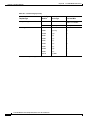
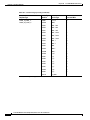
Table 2-1 describes NPM front card memory and memory expansion capability for all three NPM front
card versions.The switch software image is stored in the dynamic RAM (DRAM), with non-volatile
Flash electrically-erasable programmable ROM (EEPROM) supporting switch software image
download over the attached network. Battery-backup RAM (BRAM) stores system configuration data.
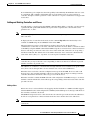
Figure 2-2
NPM Faceplate
System
status
Access
port
Fail
Active
H8314
NPM
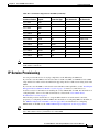
Table 2-1
NPM Front Card Memory and Expansion Capacity
NPM Version
DRAM
BRAM
Flash EEPROM
NPM-32
32 MB
1 MB
4 MB
NPM-64
64 MB
1 MB
4 MB
NPM-64-B
64 MB
1 MB
4 MB
Cisco IGX 8400 Series Provisioning Guide, Release 9.3.3 and Later Releases
OL-1166-04
2-3
Chapter 2
Cisco IGX 8400 Series Cards
Nodal Processor Module
NPM Failovers and Card Redundancy
In a nonredundant system, the NPM front card resides in either slot 1 or slot 2 (see the “Disabling NPM
Redundancy” section on page 2-4 for information on disabling NPM redundancy). In a redundant system
with two NPM front cards, the front cards reside in slot 1 and slot 2. A utility bus in the backplane
connects redundant NPMs.
Redundant NPMs have automatic failover, with the redundant card becoming active as soon as a failure
occurs on the primary NPM. The failed NPM will report an alarm condition through the fail LED on the
failed card’s faceplate.
In automatic failover, configuration and operational information changes are shared by both cards as
they occur.
Disabling NPM Redundancy
NPMs are shipped with NPM redundancy enabled.However, if you have only one NPM installed in your
chassis, your node will continue to report a minor alarm until you disable NPM redundancy on that node.
To disable NPM redundancy, use the following procedure.
Step 1
Log in to the IGX node at the SuperUser level.
Step 2
At the switch software CLI, disable NPM redundancy with the switch software cnfnodeparm 16 n
command.
Step 3
Log out of the IGX node.
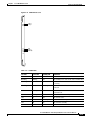
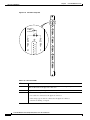
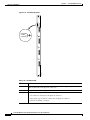
System Clock Module Back Card
The system clock module (SCM) back card provides the main clock generation function for the IGX.
The SCM phase-locks internal IGX timing to the selected clock source for network synchronization. The
SCM also measures cabinet temperature and provides external interfaces for network management
access to the node.
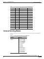
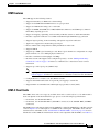
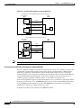
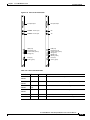
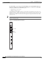
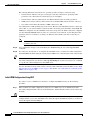
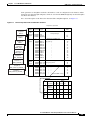
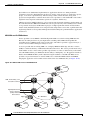
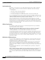
Each SCM has the following external interfaces (see Figure 2-3):
•
One 25-pin EIA/TIA-232 DCE control connector for terminal or PC access to the CLI
•
One 25-pin EIA/TIA-232 DCE auxiliary connector with multiple configurable functions
•
One 15-pin 802.3 LAN AUI connector for Telnet access to the CLI (for pin information, see
Table 2-3)
•
One 15-pin external clock input connector to allow network synchronization signals from an
EIA/TIA-422 external clock source (external clock signals must be at either 1.544 or 2.048 MHz)
•
One power supply monitor connector to measure power supply voltages and cabinet temperature
(for pin information, see Table 2-4)
Cisco IGX 8400 Series Provisioning Guide, Release 9.3.3 and Later Releases
2-4
OL-1166-04
Chapter 2
Cisco IGX 8400 Series Cards
Nodal Processor Module
Figure 2-3
SCM Faceplate
SCM
External
clock
(DB-15)
Control
terminal
(DB-25)
Auxiliary
port
(DB-25)
LAN AUI
(DB-15)
H8315
Power supply monitor (PSM)
Fail (red)
Active (green)
For a description of the SCM LEDs, see Table 2-2.
Table 2-2
SCM LEDs
LED
Color
Meaning
Fail
Red
An error has occurred. For information on troubleshooting the SCM, see
the “Troubleshooting an IGX Node” section on page 4-1 in the
Cisco IGX 8400 Series Installation Guide.
Active
Green
The card is in service.
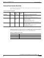
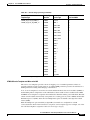
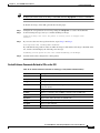
Table 2-3
LAN AUI Connector Pin Assignments (DB-15 Connector)
Pin Number
Pin Name
1
Shield
2
Collision presence +
3
XMT +
4
Reserved
Cisco IGX 8400 Series Provisioning Guide, Release 9.3.3 and Later Releases
OL-1166-04
2-5
Chapter 2
Cisco IGX 8400 Series Cards
Nodal Processor Module
Table 2-3
LAN AUI Connector Pin Assignments (DB-15 Connector) (continued)
Pin Number
Pin Name
5
RCV +
6
Power return
7
Reserved
8
Reserved
—
—
9
Collision presence -
10
XMT -
11
Reserved
12
RCV -
13
Power (+12V)
14
Reserved
15
Reserved
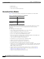
Table 2-4
Power Supply Monitor Pin Assignments (RJ-45 Connector)
Pin Number
Pin Name
1
Digital ground
2
AACFAIL *_OUT
3
BACFAIL *_OUT
The power supply monitor connector allows you to connect an external power supply monitor.
Pins 2 and 3 indicate the status of the power supplies. These pins are TTL binary logic signals, with a
value of zero indicating a power supply failure and a value of one indicating normal power supply
operation. To use the power supply monitor connector, you need a device that responds with a fail
condition when a zero TTL logic level is present on pin 2 or pin 3.
Caution
Do not use the RJ-45 connector on the SCM back card to connect your PC or terminal to the IGX. Power
from the power supply monitor connector will cause damage to your PC or terminal.
Failovers and Card Redundancy
The SCM has integrated, independently-operating internal clock circuitry and phase-lock loops, with
one clock circuit operating system bus A and the other clock circuit off system bus B. If the system bus
A fails, the SCM fails over to the system bus B clock circuitry and the fail LED will turn on. Node
operations will not be affected by SCM back card fail over.
Lower-priority SCM circuits, such as external clock input, control and auxiliary connectors, and power
supply, cabinet temperate, and fan monitoring circuits are not duplicated. Failure of lower-priority
circuits does not cause a system failure, but the SCM reports an alarm.
Cisco IGX 8400 Series Provisioning Guide, Release 9.3.3 and Later Releases
2-6
OL-1166-04
Chapter 2
Cisco IGX 8400 Series Cards
Nodal Processor Module
Each operating IGX node must have an SCM. Removal of the SCM disrupts system operation. The SCM
resides in back card slot 1 (for information on installing back cards, see the Installing the IGX chapter
in the Cisco IGX 8400 Series Installation Guide).
Tip
One SCM is sufficient to support redundant NPM front cards.
External Clock Sources
The external clock connector is a 15-pin input designed to allow network synchronization signals from
an EIA/TIA-422 external clock source. The external clock signal must be 1.544 MHz or 2.048 MHz.
The external clock source can be configured as a primary, secondary, or tertiary clock source.
Trunk or line inputs can also serve as a source for timing for the node. If no clock source is detected, the
node will use the internal IGX clock (on the SCM) as the clock source for the node.
An external clock source can be connected to the SCM card using the external clock adapter cable. The
external clock device can be either 1.544 MHz or 2.048 MHz EIA/TIA-422 square wave signals.
Selection is made through software.
For information on configuring external clock sources for an IGX node, see the “Making External Clock
Connections” section on page 3-47 in the Cisco IGX 8400 Series Installation Guide.
NPM Installation
The active and redundant NPMs must be installed in slots 1 and 2. The NPM front card and SCM back
card use a standard IGX card installation (see the “Inserting the Cards” section on page 3-8 in the
Cisco IGX 8400 Series Installation Guide).
NPM Management
Primary management tasks include maintaining and upgrading the switch software and firmware images
for the IGX node, monitoring alarm states, and collecting statistics. In addition, Cisco recommends
exercising redundant NPMs occasionally using the switch software command, switchcc.
Switch Software Management
Switch software management tasks can be conducted through a network management station running a
network management program, such as Cisco WAN Manager, or through using the switch software
command-line interface (CLI).
Replacing or Upgrading the Switch Software
Before upgrading the switch software on a node, confirm the compatibility of the switch software and
the firmware image(s) found on the cards installed in the node. Some switch software upgrades may
require an additional firmware upgrade on some or all of the cards installed in the node.
For information on switch software and firmware compatibility, see the Compatibility Matrix at
http://www.cisco.com/kobayashi/sw-center/sw-wan.shtml.
Cisco IGX 8400 Series Provisioning Guide, Release 9.3.3 and Later Releases
OL-1166-04
2-7
Chapter 2
Cisco IGX 8400 Series Cards
Alarm Relay Module
Note
If a firmware image upgrade is necessary for a card installed in the node, you may need to upgrade the
card’s firmware before upgrading the switch software image to avoid operational problems in your
network. Check the firmware release notes for specific information on upgrade procedures.
Optional Peripherals
At least one node in a network should have a Cisco WAN Manager terminal, a control terminal, or a
dial-in modem connected to it. Any control terminal connected in the network can configure, manage,
monitor, and diagnose the entire network. In addition, at least one node in a network can have a
connected printer for error and event reports.
The control terminal and printer connect to two EIA/TIA-232 serial ports. These ports are the control
terminal and auxiliary port on the SCM faceplate. These serial ports support all standard asynchronous
data rates from 1200 to 19,200 bps. The default rate is 9600 bps. Data rates and the type of equipment
connected to the ports are software-configurable.
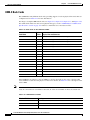
Alarm Relay Module
The IGX alarm interface module consists of an alarm relay module (ARM) front card and an alarm relay
interface (ARI) back card.
The module performs the following major functions:
•
Provides alarm summary outputs through use of relay contact closures
•
Provides a visual indication of an IGX node alarm through the ARM faceplate
•
Provides a visual alarm history indication
Note
Alarm reporting through the alarm interface module is separate from alarm output to the node’s
control port which provides alarm data to a control terminal such as a CWM network
management station.
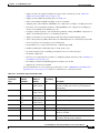
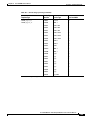
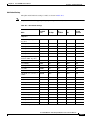
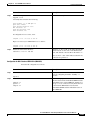
One set of alarm relays signals a major or minor alarm on the node, with one pair of contacts on each
relay being used for audible alarms. The other set of relay contacts is used for visual alarms (see
Table 2-5).
.
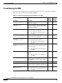
Table 2-5
Alarm Relay Module Alarm Reporting
Type
Severity
Indicator
ARM Action
Network
Major
None
Single form C relays are normally open.
Network
Minor
None
Single form C relay are normally open or
normally closed.
Node
Major
Major LED
(red)
Visual and audible relays are normally open.
Node
Minor
Minor LED
(yellow)
Visual and audible form C relays are normally
open or normally closed.
Cisco IGX 8400 Series Provisioning Guide, Release 9.3.3 and Later Releases
2-8
OL-1166-04
Chapter 2
Cisco IGX 8400 Series Cards
Alarm Relay Module
Table 2-5
Tip
Alarm Relay Module Alarm Reporting (continued)
Type
Severity
Indicator
ARM Action
Alarm cutoff
–
ACO LED
(green)
Interrupts audible relay closed.
Alarm history
–
Hist LED
(green)
None.
To turn off audible alarms, use the faceplate alarm cutoff (ACO) switch. When the ACO switch is
activated, a faceplate ACO indicator is lit as a reminder to the user. If the ACO switch is activated to
disable the node’s audible alarm output and a second alarm occurs, the audible alarm is re-activated.
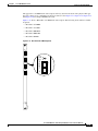
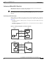
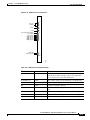
Alarm Relay Module Front Card
The ARM front card requires the ARI back card for proper functioning. Alarm relays are controlled by
switch software through control bus commands. Because the ARM does not handle user data, there is no
ARM connection to the cell bus.
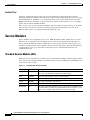
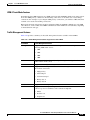
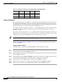
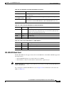
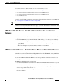
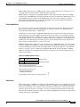
The ARM faceplate contains the alarm, active, and fail LEDs, and the ACO and history clear push
buttons (see Figure 2-4 and Table 2-6).
The ARM periodically runs a background self-test to determine the state of the card. If the card fails this
self-test, the faceplate fail LED turns on, and the active LED turns off.
Cisco IGX 8400 Series Provisioning Guide, Release 9.3.3 and Later Releases
OL-1166-04
2-9
Chapter 2
Cisco IGX 8400 Series Cards
Alarm Relay Module
Figure 2-4
ARM Front Card Faceplate
Minor
Major
ACO
HST
MINOR
MAJOR
ACO
HST
ACO
ACO
HST CLR
HST CLR
Fail
Active
FAIL
ACTIVE
H8332
ARM
Table 2-6
ARM Front Card LEDs
Faceplate Item
Meaning or Description
Minor LED (yellow)
A failure in the local node that is not service-affecting but should be
investigated. It could indicate problems such as a loss of redundancy, a
low error rate on a digital trunk (frame bit errors or bipolar errors), or other
problems.
Major LED (red)
A failure in the local node that is service-affecting and should immediately
be investigated.
ACO LED (white)
A minor or major alarm is present, and the alarm cutoff (ACO) button was
pressed to silence an accompanying audible alarm. The ACO light turns
off when the alarm is cleared.
HISTory LED (green)
An alarm on the node has occurred sometime in the past. The alarm might
be current or might have been cleared. By pressing the HIST CLR button,
you can turn off this light if there is no current alarm.
Fail LED (red)
The card has failed self-test. Reset the card using the switch software
resetcd f command.
Active LED (green)
The card is active, has been assigned through the switch software
addalmslot command, and is functioning normally.
Cisco IGX 8400 Series Provisioning Guide, Release 9.3.3 and Later Releases
2-10
OL-1166-04
Chapter 2
Cisco IGX 8400 Series Cards
Alarm Relay Module
Table 2-6
ARM Front Card LEDs (continued)
Faceplate Item
Meaning or Description
ACO push button
When pressed, this button silences the audible alarm and turns on the ACO
LED. Visual alarms remain on.
HIST CLR push button
When pressed, this button turns off the HIST LED if there are no current
alarms.
Alarm Relay Interface Back Card
The alarm relay interface (ARI) back card contains the alarm relays and their associated relay drivers.
Alarm outputs are dry contact closures from form C relays. The user must supply the voltage source to
be switched by the IGX. Any source or load can be switched if it meets the following requirements:
•
Voltage source, maximum 220 volts
•
Steady-state current, maximum 0.75 amps
•
Power dissipation, maximum 60 watts
A female DB-37 connector resides on the faceplate for connection to the customer’s office alarm or
alarm-reporting system. For information on connector pinouts, see the “External Alarm Cabling” section
on page A-50 in the Cisco IGX 8400 Series Installation Guide.
Refer to Figure 2-5 for an illustration of the ARI faceplate.
Cisco IGX 8400 Series Provisioning Guide, Release 9.3.3 and Later Releases
OL-1166-04
2-11
Chapter 2
Cisco IGX 8400 Series Cards
Alarm Relay Module
Figure 2-5
ARI Faceplate
ARI
5120N
DB-37
H8333
ALARM
RELAYS
ARM Configuration and Management
Enable alarm display functionality on the ARM with the switch software addalmslot command. The
ARM requires standard management and preventive maintenance tasks.
Making Alarm Relay Output Connections
To set up an ARM after installation, use the following procedure:
Step 1
Log in to the IGX node.
Step 2
Enter the switch software addalmslot slot command to activate alarm reporting from the card.
Step 3
Check the active LED on the front card faceplate.
Step 4
Test alarm output operation by creating an alarm on the node.
Tip
Create an alarm by disconnecting a trunk cable from the connector on the back card.
Cisco IGX 8400 Series Provisioning Guide, Release 9.3.3 and Later Releases
2-12
OL-1166-04
Chapter 2
Cisco IGX 8400 Series Cards
Alarm Relay Module
Caution
To avoid disruption of necessary network traffic, do not generate a major alarm during periods of high
network traffic.
Step 5
Check that the major LED lights up on the front card faceplate of the ARM.
Step 6
Using a voltage/ohm meter (VOM), make sure continuity exists between pins 16 and 17 and between
pins 35 and 36 at the DB-37 connector on the ARI card.
Step 7
Remove the alarm from the node by restoring the connection you disabled in Step 4.
Step 8
With the VOM, check that the reading between pins 16 and 17 and pins 35 and 36 are open and the major
LED is not on.
Alarm output connections are made at the DB-37 connector on the ARI card. The connector pin
assignments with the alarm signal names are listed in Table 2-7.
Table 2-7
ARI Alarm Connector Pinouts
Pin Number
Alarm Type
Alarm Name
Alarm Description
1
–
CHASSIS
Protective ground
3
Network
NWMAJA
Major—Normally open contact
22
Network
–
Major—Normally closed contact
4
Network
NWMAJC
Major—Common contact
10
Node
MNVISA
Minor visual—Normally open contact
11
Node
–
Minor visual—Normally closed contact
12
Node
MNVISC
Minor visual—Common contact
16
Node
MJAUDC
Major audible—Common contact
17
Node
MJAUDA
Major audible—Normally open contact
23
Network
NWMINA
Minor—Normally open contact
24
Network
–
Minor—Normally closed contact
25
Network
NWMINC
Minor—Common contact
29
Node
NWAUDA
Minor audible—Normally open contact
30
Node
–
Minor audible—Normally closed contact
31
Node
NWAUDC
Minor audible—Common contact
35
Node
MJVISC
Major visual—Common contact
36
Node
MJVISA
Major visual—Normally open contact
ARM Troubleshooting
The following paragraphs describe the maintenance and troubleshooting features associated with the
ARM card set. Preventive maintenance is not necessary.
Cisco IGX 8400 Series Provisioning Guide, Release 9.3.3 and Later Releases
OL-1166-04
2-13
Chapter 2
Cisco IGX 8400 Series Cards
Service Modules
Card Self-Test
Diagnostic routines periodically run to test the card's performance. These diagnostics run in the
background and do not disrupt normal behavior. If a failure is detected during the self-test, the faceplate
red fail LED turns on. In addition, you can check the status of the card by using the switch software
dspcd command. If a card failure is reported, the report remains until cleared. To clear a card failure,
use the switch software resetcd command.
There are two types of resets: hardware and failure. The reset failure clears the event log of any failure
detected by the card self-test and does not disrupt card operation. The hardware reset reboots the
firmware and resets the card, which momentarily disables the card.
Service Modules
Service modules allow configuring of data, voice, ATM, Frame Relay (FR), and IP services over the
IGX node. In an operational network, multiple service cards may be installed in the same physical
chassis, with many different possible configurations of service types, interface connector types, and
transmission formats. These service modules can be used in any of the three chassis models. However,
careful planning of slot space and cabling is important for easy and efficient maintenance and
troubleshooting tasks.
Standard Service Module LEDs
IGX service front cards and back cards have several standard indicator LEDs on their faceplates. While
some cards may have additional LEDs, all cards have both a green active LED and a red fail LED located
at the bottom of the faceplate.
Table 2-8
Standard IGX Service Card LEDs
LED
Status
Meaning
Fail
Steady
An error has occurred. For information on troubleshooting the card,
refer to the card information listed later in this chapter.
Fail
Blinking
The back card is missing or has not been installed.
Active
Steady
The card is active and is carrying traffic or processing data.
Active
Blinking
The card is executing a card self-test.
Both LEDs
Off
The card is either redundant and in standby, or the card is not in use.
Both LEDs
On
The card has failed but remains in active state because no redundant card
is available. May also indicate specific failures in the card’s lines—refer
to the card’s troubleshooting information later in this chapter.
Cisco IGX 8400 Series Provisioning Guide, Release 9.3.3 and Later Releases
2-14
OL-1166-04
Chapter 2
Cisco IGX 8400 Series Cards
Service Modules
Standard Service Module Installation
Caution
In order to contain electromagnetic interference (EMI) and radio frequency interference (RFI), and to
ensure desired airflow for adequate chassis cooling, install a blank faceplate in any back card slots where
no back card exists.
Except where noted, IGX service modules use a standard installation procedure (see Chapter 3,
“Installing the IGX” in the Cisco IGX 8400 Series Installation Guide).
Card Redundancy
Except where noted, you can configure the service module for 1:1 redundancy by installing a second,
identical card group in another slot. Use a Y-cable to connect the two redundant back cards, then use the
switch software addyred command to add Y-redundancy to the card’s configuration. See Figure 2-6 for
an illustration.
The hardware kits for this feature usually contain a second, duplicate card set, a set of Y-cables to
interconnect the two card sets, and any other pieces that apply to the card types. Y-cable redundancy is
not possible using back cards with different interfaces, such as an FRI T1 and FRI V.35.
Figure 2-6
Y-Cable Card Redundancy on the IGX
Active cards
Front
card
Back
card
Front
card
Y cable
S5837
User
equipment
(data)
Back
card
Standby cards
Standard Service Module Configuration
For specific information on advanced card configuration tasks, refer to the information for your specific
front card and back card combination, or to Chapter 3, “Installing the IGX” in the Cisco IGX 8400 Series
Installation Guide.
Cisco IGX 8400 Series Provisioning Guide, Release 9.3.3 and Later Releases
OL-1166-04
2-15
Chapter 2
Cisco IGX 8400 Series Cards
Network Trunk Module
Standard Service Module Troubleshooting
The following paragraphs describe standard service module maintenance and troubleshooting features.
Except where noted, preventive maintenance is not necessary.
Card Mismatch
When you connect an unsupported back card to the service module front card, the output from the switch
software dspcds command informs you that you have a card mismatch.
Card Self-Test
Diagnostic routines periodically run to test the card's performance. These diagnostics run in the
background and do not disrupt normal traffic. If a failure is detected during the self-test, the faceplate
red fail LED turns on. In addition, you can check the status of the card by using the switch software
dspcd command at the control terminal. If a card failure is reported, the report remains until cleared. To
clear a card failure, use the switch software resetcd command.
There are two types of resets: hardware and failure. The failure reset clears the event log of any failure
detected by the card self-test and does not disrupt card operation. The hardware reset reboots the
firmware and resets the card, which momentarily disables the card.
Network Trunk Module
Table 2-9 shows supported front and back cards for the network trunk module (NTM).
Table 2-9
Network Trunk Module Front Card and Back Cards
Front Card
Back Cards
NTM
BC-T1
BC-E1
BC-Y1
BC-SR
The NTM enables FastPacket transmission on a trunk established between two IGX nodes. NTM
features include the following:
•
Takes FastPackets off the cellbus and places them in queues before transmission to the trunk
•
Arbitrates access to the trunk for the traffic type
•
Monitors the age of each timestamped FastPacket, updates the timestamp for FastPackets at
intermediate nodes, and discards FastPackets that exceed age limit
•
Receives and checks FastPackets from the trunk and queues them for transmission to the cellbus
•
Provides packet alignment based on the CRC in the FastPacket header
•
Extracts clocking from the trunk that can be used as a clock source on the node or as a clock path
•
Collects trunk usage statistics
Cisco IGX 8400 Series Provisioning Guide, Release 9.3.3 and Later Releases
2-16
OL-1166-04
Chapter 2
Cisco IGX 8400 Series Cards
Network Trunk Module
NTM Front Card
Note
There are two variants of the NTM front card: one uses an ACM1 adapter to connect two legacy card
designs and the other is a single card version built for the IGX chassis. While functionally identical, their
firmware cannot be interchanged. The single-card NTM requires firmware revision F or later.
An NTM front card can occupy any available front service card slot (slots 3 to 32). The module’s back
card depends on the desired trunk interface type. See the following usage information:
•
For a T1 or fractional T1 trunk, use the BC-T1 back card.
•
For a E1 or fractional E1 trunk, use the BC-E1 back card.
•
For a Y1 or fractional Y1 trunk, use the BC-Y1 back card.
•
For a subrate trunk, use the BC-SR back card; transmission rates range from 64 to 1920 kbps.
EIA/TIA-449, X.21, and V.35 connectors are available on the back cards.
For a description of the NTM front card faceplate, see Figure 2-7.
Figure 2-7
NTM Front Card Faceplate
Minor
Major
Fail
Active
H9610
BTM
Cisco IGX 8400 Series Provisioning Guide, Release 9.3.3 and Later Releases
OL-1166-04
2-17
Chapter 2
Cisco IGX 8400 Series Cards
Network Trunk Module
NTM T1 Interface Back Card
The NTM T1 interface back card (BC-T1) terminates a single 1.544 Mbps T1 trunk on the network trunk
module in the IGX, and provides the following features:
•
AMI and B8ZS (bipolar 8 zero-suppress) line codes
•
D4 and extended super-frame (ESF) framing formats
•
Configurable full or fractional T1 service
•
Configurable line buildouts for cable lengths up to 655 feet
•
Configurable clock modes (normal clocking and loop timing)
•
Communication of line event information to the NTM front card
The BC-T1 uses a DB-15 interface connector (see Figure 2-8) and has loss of signal and loss of
FastPacket alignment indicators on the back card faceplate (see Table 2-10).
Figure 2-8
BC-T1 Back Card Faceplate
BC-T1
T1 input/output
LOS (red)
Red alarm (red)
Yellow alarm (yellow)
AIS (green)
H8316
Fail (red)
Active (green)
Cisco IGX 8400 Series Provisioning Guide, Release 9.3.3 and Later Releases
2-18
OL-1166-04
Chapter 2
Cisco IGX 8400 Series Cards
Network Trunk Module
Table 2-10 BC-T1 Back Card Faceplate LEDs
LED
Meaning
LOS (red)
Loss of signal at the local end of the trunk.
Alarm LED (red)
Loss of local T1 frame alignment or loss of FastPacket alignment on the
local end of the trunk.
Alarm LED (yellow)
Loss of remote T1 frame alignment or loss of FastPacket alignment on the
remote end of the trunk.
AIS (green)
Presence of an unframed sequence of all-ones on the T1 line.
NTM E1 Interface Back Card
The NTM E1 interface card (BC-E1) terminates an E1 trunk line on the NTM front card, and provides
the following features:
•
Physical interfaces to CEPT E1 lines (CCITT G.703 specification)
•
120-ohm (balanced) or 75-ohm (balanced or unbalanced) physical interfaces
•
Support for HDB3 or AMI
•
Configurable full or fractional E1 lines
•
Communication of E1 line events to the NTM front card
•
Detection of loss of FastPacket synchronization
•
CRC-4 error checking
•
Configurable clock modes—normal clocking and loop timing
Figure 2-9 and Table 2-11 provide descriptions of the BC-E1 status LEDs and connectors on the BC-E1
faceplate.
Table 2-11 BC-E1 Back Card LEDs
LED
Meaning
LOS
Loss of signal at the local end.
Alarm LED (red)
Loss of local frame alignment or FastPacket alignment on the local end.
Alarm LED (yellow) Loss of remote frame alignment or FastPacket alignment on the remote end.
AIS (green)
Presence of unframed all-ones on the E1 line.
MFRA (red)
Loss of multiframe alignment on the local end.
MFYA (yellow)
Loss of multiframe alignment on the remote end.
Cisco IGX 8400 Series Provisioning Guide, Release 9.3.3 and Later Releases
OL-1166-04
2-19
Chapter 2
Cisco IGX 8400 Series Cards
Network Trunk Module
Figure 2-9
BC-E1 Faceplate
BC-E1
RX/TX
RX
TX
LOS (red)
Red alarm (red)
Yellow alarm (yellow)
AIS (green)
MFRA (red)
MFYA (yellow)
H8317
Fail (red)
Active (green)
NTM Y1 Interface Back Card
The NTM Y1 interface back card (BC-Y1) terminates a Y1 line on the NTM front card, and provides the
following features:
•
Physical interfaces to Japanese trunks (Y1)
•
Support for coded mark inversion (CMI) line coding
•
Support for Y1 trunk-formatted signaling
•
Support for 24-channel, 1.544 Mbps operation
•
Support for fractional rates
•
Statistics reporting for Y1 line events (such as loss of framing, loss of signal, and framing errors)
•
Configurable clock modes—normal clocking and loop timing
Figure 2-10 and Table 2-12 provide descriptions of the BC-Y1 status LEDs and connectors on the
faceplate.
Cisco IGX 8400 Series Provisioning Guide, Release 9.3.3 and Later Releases
2-20
OL-1166-04
Chapter 2
Cisco IGX 8400 Series Cards
Network Trunk Module
Figure 2-10 BC-Y1 Faceplate
BC-Y1
Y1 trunk input/output
Line in
Line out
RXMON - monitor jack
TXMON - monitor jack
LOS (red)
Red alarm (red)
Yellow alarm (yellow)
AIS (green)
H8319
Fail (red)
Active (green)
Table 2-12 BC-Y1 Back Card LEDs
LED
Meaning
LOS (red)
Loss of signal at the local end.
Red alarm (red)
Loss of local frame alignment.
Yellow alarm (yellow)
Loss of frame alignment at the remote end.
AIS (green)
Presence of unframed all-ones on the line.
NTM Subrate Interface Back Card
The subrate interface back card (BC-SR) terminates subrate trunks on the NTM. The BC-SR provides
the following features:
•
Trunk rates of 256 kbps, 768 kbps, 1024 kbps, 1536 kbps, and 1920 kbps
•
V.11/X.21, V.35, and EIA/TIA-449 interface connectors (see Figure 2-11)
•
Synchronization of the trunk clocking with looped clock option (not applicable to X.21)
•
A limited set of EIA control leads monitored by the system (see Table 2-14)
Cisco IGX 8400 Series Provisioning Guide, Release 9.3.3 and Later Releases
OL-1166-04
2-21
Chapter 2
Cisco IGX 8400 Series Cards
Network Trunk Module
Because a subrate trunk facility interface operates in DCE mode with the subrate channel functioning
like a synchronous data channel, the BC-SR back card always operates in DTE mode. Subrate trunks
cannot pass clock signals, so you must make provisions for separate clock signalling sources for each
IGX node connected to the network solely through subrate trunks (see the “Connecting an NTM E1 or
Subrate Trunk” section on page 3-17 in the Cisco IGX 8400 Series Installation Guide).
Figure 2-11 BC-SR Faceplate
BC-SR
RS 449/MIL188
X.21
V.35
LOS (red)
Bad Clk (red)
Yellow alarm (yellow)
DSR (green)
DTR (green)
RXD (green)
TXD (green)
H8318
Fail (red)
Active (green)
Table 2-13 BC-SR Back Card LEDs
LED
Meaning
LOS (red)
Loss of signal at the local end.
Bad CLK (red)
Loss of clock or clock out of range.
Alarm (yellow)
Loss of FastPacket alignment at remote end.
DSR (green)
The DSR lead is high (on).
DTR (green)
The DTR lead is high (on).
RXD (green)
The receive data line shows activity.
TXD (green)
The transmit data line shows activity.
Cisco IGX 8400 Series Provisioning Guide, Release 9.3.3 and Later Releases
2-22
OL-1166-04
Chapter 2
Cisco IGX 8400 Series Cards
Universal Switching Module
Table 2-14 Data and Control Leads Supported with the BC-SR Back Card
Function
Lead
Name
Interface
Transmit
TX
Transmit data
All
Transmit
RTS
Request to send
V.35
Transmit
DTR/C
Data terminal ready
All
Transmit
LL
Local loop
EIA/TIA-422
Transmit
RL
Remote loop
EIA/TIA-422
Transmit
IS
Terminal in service
EIA/TIA-422
Transmit
SS
Select standby
V.35
Transmit
SF
Sig rate select
–
Receive
RX
Receive data
All
Receive
CTS
Clear to send
V.35
Receive
DSR/I
Data set ready
All
Receive
DCD
Data carrier select
V.35
Receive
RI/IC
Ring incoming call
V.35
Receive
TM
Test mode
V.35
Receive
SB
Standby indicator
–
Receive
SI
Signalling rate
–
Universal Switching Module
Table 2-15 shows the front and back cards supported for the universal switching module (UXM and
UXM-E).
Table 2-15 Universal Switching Module Front and Back Cards
Front Card
Back Card
UXM
UXM-E
BC-UAI-4-155-MMF
BC-UAI-4-155-SMF
BC-UAI-2-155-SMF
BC-UAI-2-SMFXLR
BC-UAI-4-SMFXLR
BC-UAI-4-STM1E
BC-UAI-6-T3
BC-UAI-3-T3
BC-UAI-6-E3
BC-UAI-3-E3
BC-UAI-4-T1-DB-15
BC-UAI-8-T1-DB-15
BC-UAI-4-E1-DB-15
BC-UAI-8-E1-DB-15
BC-UAI-4-E1-BNC
BC-UAI-8-E1-BNC
Cisco IGX 8400 Series Provisioning Guide, Release 9.3.3 and Later Releases
OL-1166-04
2-23
Chapter 2
Cisco IGX 8400 Series Cards
Universal Switching Module
Note
Information for the enhanced universal switching module (UXM-E) also applies to the UXM. For
differences between the two cards, refer to the release notes for your card.
The enhanced universal switching module (UXM-E) provides ATM trunk and line service for the IGX.
In trunk mode, the UXM-E supports network trunks and in port mode, the UXM-E supports either an
ATM user-to-network interface (UNI) or a network-to-network interface (NNI). The back cards support
multiple physical connector types, with ports operating at OC3/STM1, T3, E3, T1, or E1 rates.
The UXM-E can transport ATM cells to and from the IGX cellbus at a maximum rate of 310 Mbps in
each direction. This maximum rate applies regardless of back card type.
Switch software limits the number of logical trunks and lines that can be configured on an IGX node as
shown below:
•
Maximum number of logical trunks on an IGX node: 32
•
Maximum number of lines on an IGX node: 64
These limits are independent of the number of UXM or UXM-E cards in the IGX switch chassis, because
switch software monitors the number of configured lines and trunks, not the number of cards that are
physically present.
When you reach these limits, switch software prevents activation of additional trunks or lines on the
node, and you see an error message.
The UXM and UXM-E also support the following features for both trunk and port modes:
•
Enhanced ABR support for connections with non-ATM AAL5 traffic to minimize the risk of RM
cell starvation.
•
Allows 8000 connections in either trunk, port, or mixed modes.
Note
The UXM and UXM-E cannot support more than 4000 gateway connections. All remaining
connections can be user or networking connections. For example, if you configure 2500
gateway connections onto a UXM-E, you still have 5500 possible user or networking
connections.
•
Supports 8000 connections concurrently with level-1 and level-2 statistics, and 4000 connections
with level-3 statistics.
•
Provides real-time statistics counters and interval statistics collection for ports, lines, trunks, and
channels.
•
Supports arbitrary assignments for VPIs and VCIs for each virtual circuit (VC).
•
Supports ATM standards-based inverse multiplexing (IMA) to allow logical trunk or line formation
from a grouping of more than one T1 or E1 interface.
•
Provides 128,000 cell buffers.
•
Uses all four lanes on the IGX cellbus.
•
Supports Y-cable redundancy with hot standby.
For information on initial configuration of a UXM-E, see the “UXM-E Configuration” section on
page 2-33.
Cisco IGX 8400 Series Provisioning Guide, Release 9.3.3 and Later Releases
2-24
OL-1166-04
Chapter 2
Cisco IGX 8400 Series Cards
Universal Switching Module
UXM-E Trunk Mode Features
In trunk mode, the UXM-E supports up to 8000 connections. The UXM-E in trunk mode cannot support
more than 4000 gateway connections. All remaining connections can be either user or networking
connections. For example, if you configure 2500 gateway connections, you still have 5500 connections
available to be used for networking connections.
Between the network and customer premise equipment (CPE), the UXM-E communicates only ATM
cells. However, on the cellbus, the UXM-E communicates either ATM cells or FastPackets, depending
on the destination card type.
Traffic Management Features
Table 2-16 provides a summary of the traffic management features available on the UXM-E.
Table 2-16 Traffic Management Features Supported on the UXM-E
Card Mode
Traffic Management Feature
Both (port & trunk) Supports ATM-to-FR service interworking, network interworking, and the
following ATM traffic classes:
•
CBR
•
VBR
•
ABR
•
UBR
Both
Supports partial packet discard (or tail packet drop) and early packet discard for
AAL5 virtual circuits (VCs)
Both
Supports user-configurable congestion thresholds
Trunk
Supports the following additional traffic classes through FastPacket-based or
interworked connections:
•
High-priority
•
Timestamped
•
Non-timestamped
•
Bursty data A
•
Bursty data B
Port (UNI/NNI)
Supports PCR-linked policing of ABR connections
Port
Supports the following control options for ABR connections where the ABR
control loop does not terminate at the connection endpoints:
•
EFCI
•
Relative rate
•
Explicit rate
Cisco IGX 8400 Series Provisioning Guide, Release 9.3.3 and Later Releases
OL-1166-04
2-25
Chapter 2
Cisco IGX 8400 Series Cards
Universal Switching Module
Table 2-16 Traffic Management Features Supported on the UXM-E (continued)
Card Mode
Traffic Management Feature
Port
Supports the following ABR options:
•
End-to-end (ABR loop) excluding VS/VD
•
VS/VD-segmented ABR within a network, and ABR on external segments
•
VS/VD-segmented ABR within a network and UBR or VBR on external
segments
•
ForeSight within a network and UBR or VBR on external segments
•
ForeSight within a network and ABR on external segments
Port
Supports per-VC queuing for ABR or UBR connections
Port
Supports frame-based GCRA policing on AAL5 VCs
Port
Supports per-VC queuing for statistics for all connection types
Port
Supports user-configurable, per-VC congestion thresholds
UXM-E Front Card
The UXM-E front card faceplate has five LEDs (see Figure 2-12). These LEDs indicate card status
through different combinations of the fail, active, and standby LEDs. Use Table 2-17 during UXM-E
troubleshooting (for more information on UXM-E troubleshooting, see the “UXM-E Troubleshooting”
section on page 2-34).
Cisco IGX 8400 Series Provisioning Guide, Release 9.3.3 and Later Releases
2-26
OL-1166-04
Chapter 2
Cisco IGX 8400 Series Cards
Universal Switching Module
Figure 2-12 UXM-E Front Card
Minor
Major
Fail
Active
Standby
29424
UXME
Table 2-17 UXM-E LEDs
Fail LED
Active LED
Standby LED
Card Status
On
Off
Off
The card has failed.
Blinking
Blinking
Off
The standby front card’s back card is mismatched.
Blinking
On
Off
The active front card’s back card is mismatched
or missing.
Blinking
Off
Blinking
The front card’s self-test indicates a back card
mismatch.
Off
Blinking
On
The standby front card’s self-test indicates a back
card mismatch.
Off
Blinking
Off
The card is the hot standby.
Off
On
Off
The card is active.
Off
Off
Blinking
The card is conducting a self-test.
Off
Off
On
The card is in standby.
On
On
On
The card is down.
Cisco IGX 8400 Series Provisioning Guide, Release 9.3.3 and Later Releases
OL-1166-04
2-27
Chapter 2
Cisco IGX 8400 Series Cards
Universal Switching Module
UXM-E Back Cards
The UXM-E has many different back cards, providing support for various physical line and connector
configurations. See Table 2-18 for more information.
For images of sample UXM-E back cards, see Figure 2-13, Figure 2-14, Figure 2-15, and Figure 2-16.
For technical information on the various physical line types, see the “UXM-E Physical and Electrical
Specifications” section on page A-4 in the Cisco IGX 8400 Series Installation Guide.
Table 2-18 Back Cards for the UXM and UXM-E
Card Name
Number
of Ports
Physical Line and Connector
BC-UAI-4-155-MMF
4
OC-3/STM1, multi-mode fiber, 155 Mbps, with SC connectors
BC-UAI-4-155-SMF
4
OC-3/STM1, single-mode fiber, 155 Mbps, with SC connectors
BC-UAI-2-155-SMF
2
OC-3/STM1, single-mode fiber, 155 Mbps, with SC connectors
BC-UAI-2-SMFXLR
2
OC-3/STM1, single-mode fiber XLR, with SC connectors
BC-UAI-4-SMFLXR
4
OC-3/STM1, single-mode fiber XLR, with SC connectors
BC-UAI-4-STM1E
4
OC-3/STM1, with synchronous transfer module-1E
BC-UAI-6-T3
6
T3, with SMB connectors
BC-UAI-3-T3
3
T3, with SMB connectors
BC-UAI-6-E3
6
E3, with SMB connectors
BC-UAI-3-E3
3
E3, with SMB connectors
BC-UAI-4-T1-DB-15
4
T1 with DB-15 connectors
BC-UAI-8-T1-DB-15
8
T1 with DB-15 connectors
BC-UAI-4-E1-DB-15
4
E1 with DB-15 connectors
BC-UAI-8-E1-DB-15
8
E1 with DB-15 connectors
BC-UAI-4-E1-BNC
4
E1 with BNC connectors
BC-UAI-8-E1-BNC
8
E1 with BNC connectors
Most UXM-E back cards have a tricolor LED for each line that indicates the status of the line. This
tricolor LED is located above the physical connector for the line. See Table 2-19 for a description of the
tricolor LED.
Note
The T1 and E1 back cards do not have the standard service module active and fail LEDs to indicate card
status. If a T1 or E1 back card failure is detected, all of the tricolor LEDs on the back card turn red.
Table 2-19 UXM-E Back Card LEDs
Tricolor LED Color
Meaning
Red
The line is active but a local alarm exists.
Yellow
The line is active but a remote alarm exists.
Green
The line is active with no alarms.
Cisco IGX 8400 Series Provisioning Guide, Release 9.3.3 and Later Releases
2-28
OL-1166-04
Chapter 2
Cisco IGX 8400 Series Cards
Universal Switching Module
The appearance of UXM-E back card faceplates will vary based on the back card’s physical line type,
physical connector type, and number of physical connectors. See Figure 2-13, Figure 2-14, Figure 2-15,
and Figure 2-16 for sample UXM-E back cards.
Figure 2-13 shows a BC-UAI-4-155-SMF back card faceplate. The following back cards have similar
faceplates:
•
BC-UAI-4-155-MMF
•
BC-UAI-2-155-SMF
•
BC-UAI-2-SMFXLR
•
BC-UAI-4-SMFLXR
•
BC-UAI-4-STM1E
Figure 2-13 BC-UAI-4-155-SMF Faceplate
UAI- 4-155
SMF
R LOC
Y REM
G OK
P
O
R
T
R
X
T
X
1
R LOC
Y REM
G OK
P
O
R
T
R LOC
Y REM
G OK
R
X
T
X
2
P
O
R
T
R LOC
Y REM
G OK
P
O
R
T
R
X
T
X
3
R LOC
Y REM
G OK
P
O
R
T
R
X
2
R
X
T
X
T
X
4
FAIL
H11697
ACTIVE
Cisco IGX 8400 Series Provisioning Guide, Release 9.3.3 and Later Releases
OL-1166-04
2-29
Chapter 2
Cisco IGX 8400 Series Cards
Universal Switching Module
Figure 2-14 shows a BC-UAI-6-T3 back card faceplate. The following back cards have similar
faceplates:
•
BC-UAI-3T3
•
BC-UAI-6-E3
•
BC-UAI-3-E3
Figure 2-14 BC-UAI-6-T3 Faceplate
UAI
6T3
R LOC
Y REM
G OK
TX
P
O
R
T
1
RX
R LOC
Y REM
G OK
R LOC
Y REM
G OK
TX
P
O
R
T
2
TX
RX
P
O
R
T
R LOC
Y REM
G OK
TX
P
O
R
T
3
RX
2
R LOC
Y REM
G OK
TX
RX
P
O
R
T
4
RX
R LOC
Y REM
G OK
TX
P
O
R
T
5
RX
R LOC
Y REM
G OK
TX
P
O
R
T
6
RX
FAIL
H11699
ACTIVE
Figure 2-15 shows a BC-UAI-8-T1-DB-15 back card faceplate. The following back cards have similar
faceplates:
•
BC-UAI-4-T1-DB-15
•
BC-UAI-8-E1-DB-15
•
BC-UAI-4-E1-DB-15
Cisco IGX 8400 Series Provisioning Guide, Release 9.3.3 and Later Releases
2-30
OL-1166-04
Chapter 2
Cisco IGX 8400 Series Cards
Universal Switching Module
Figure 2-15 BC-UAI-8-T1-DB-15 Faceplate
UAI-8T1
DB15
R LOC
Y REM
G OK
P
O
R
T
1
R LOC
Y REM
G OK
R LOC
Y REM
G OK
P
O
R
T
2
P
O
R
T
R LOC
Y REM
G OK
P
O
R
T
3
R LOC
Y REM
G OK
2
P
O
R
T
4
R LOC
Y REM
G OK
P
O
R
T
5
R LOC
Y REM
G OK
P
O
R
T
6
R LOC
Y REM
G OK
P
O
R
T
7
R LOC
Y REM
G OK
P
O
R
T
H11703
8
Figure 2-16 shows a BC-UAI-8-E1 BNC back card faceplate. Each BNC connector carries traffic in only
one direction. The BC-UAI-4-E1 has a similar faceplate.
Cisco IGX 8400 Series Provisioning Guide, Release 9.3.3 and Later Releases
OL-1166-04
2-31
Chapter 2
Cisco IGX 8400 Series Cards
Universal Switching Module
Figure 2-16 BC-UAI-8-E1 BNC Faceplate
UAI-8EI
BNC
PORT 1
TX
R LOC
Y REM
G OK
RX
PORT 2
PORT 2
TX
TX
R LOC
Y REM
G OK
RX
PORT 3
TX
R LOC
Y REM
G OK
R LOC
Y REM
G OK
RX
PORT 4
TX
RX
R LOC
Y REM
G OK
RX
PORT 5
TX
R LOC
Y REM
G OK
RX
PORT 6
TX
R LOC
Y REM
G OK
RX
PORT 7
TX
R LOC
Y REM
G OK
RX
PORT 8
TX
R LOC
Y REM
G OK
H11705
RX
UXM-E Installation
Tip
Switch software limits the number of logical trunks and lines that can be configured on an IGX switch.
To optimize your chassis space, do not install more than 64 lines or 32 trunks (these totals include all
lines or trunks available on all trunk or line modules in the chassis). Modules used for hot standby do
not count toward these totals.
The UXM-E uses a standard IGX card installation (see Chapter 3, “Installing the IGX” in the
Cisco IGX 8400 Series Installation Guide).
Cisco IGX 8400 Series Provisioning Guide, Release 9.3.3 and Later Releases
2-32
OL-1166-04
Chapter 2
Cisco IGX 8400 Series Cards
Universal Switching Module
UXM-E Redundancy
Like other IGX service modules, the UXM-E can be configured for Y-cable redundancy. Both cards, the
primary and the redundant, must be installed before you configure them for Y-cable redundancy.
The UXM-E features hot standby, in which the redundant card receives card configuration information
as soon as you finish specifying redundancy. The standby card also updates its configuration as the
active card configuration changes.
For more information on setting up Y-cable redundancy, see the “Card Redundancy” section on
page 2-15.
UXM-E Configuration
When you insert a new UXM-E into the backplane, or apply power to the IGX node, the UXM-E
firmware reports the card type and the number of physical lines on the back card to the node’s switch
software.
Note
On activation, the UXM-E reports the number and type of physical ports available on the attached back
card. This back card configuration information is retained by switch software even if the back card is
later removed.
To activate a trunk, use the switch software uptrk command (see Chapter 4, “Cisco IGX 8400 Series
Trunks”).
To activate a line, use the switch software upln command (see Chapter 5, “Cisco IGX 8400 Series
Lines”).
UXM-E Management
Most UXM-E management tasks are general trunk or line management tasks. See Chapter 4,
“Cisco IGX 8400 Series Trunks,” or Chapter 5, “Cisco IGX 8400 Series Lines” for more information on
managing and troubleshooting trunks or lines.
UXM-E as a Clock Source
A UXM-E line or trunk can serve as the clock source for the IGX node. To configure the clock source,
use the switch software cnfclksrc command. To display available clock sources, use the switch software
dspclksrcs command. To show the current clock source, use the switch software dspcurclk command.
For more information about clocking on IGX nodes, see “Cisco IGX 8400 Series Nodes”
Cisco IGX 8400 Series Provisioning Guide, Release 9.3.3 and Later Releases
OL-1166-04
2-33
Chapter 2
Cisco IGX 8400 Series Cards
Universal Switching Module
Y-Redundancy and VC Merge on the UXM-E
Note
Because VC merge is not supported on the UXM, y-redundancy cannot be set up using a UXM-E and a
UXM without generating a feature mismatch error. If y-redundancy is set up between a UXM-E and a
UXM, the VC merge feature cannot be enabled.
Before setting up y-redundancy on two UXM-E cards, make sure that VC merge feature support is
enabled on both cards. Both cards must run the appropriate firmware to support the VC merge feature.
For more information on enabling VC merge on the IGX, see the “VC Merge on the IGX” section on
page 10-40 in Chapter 10, “IP Service—Functional Overview.”
Note
VC merge on the IGX is not supported in releases preceding Switch Software Release 9.3.40.
UXM-E Troubleshooting
Switch software classifies UXM-E trunk statistics as physical or logical. See the following list of rules
used to distinguish physical trunk statistics from logical ones:
•
A UXM-E trunk is mapped to a physical line object.
•
A physical (nonIMA) trunk is mapped one-to-one with a physical line.
•
An IMA trunk is mapped to more than one physical line.
•
All line alarms are reported as physical line alarms.
•
Other trunk alarms (such as communication failure) are reported like NTM trunk alarms.
•
For nonIMA trunks, the alarm includes the physical line alarm.
•
For IMA trunks, the trunk and physical line alarms are separate and distinct.
Trunk Statistics on the UXM-E
The following switch software commands apply to statistics for physical lines within an IMA trunk:
•
cnfphyslnstats enables and configures physical line statistics.
•
dspphyslnstatcnf displays the current physical line statistics configuration.
•
dspphyslnstathist displays the physical line statistics.
•
dsptrkstatcnf displays the current configuration of logical trunk statistics.
•
dsptrkstathist displays logical trunk statistics.
•
dsptrkstats displays trunk statistics.
•
dspportstats displays port, IMA, and ILMI statistics for trunk ports.
•
dstrkerrs displays trunk errors.
•
clrtrkalm clears trunk alarms caused by statistical errors.
•
dspchstats displays channel statistics, such as cells received and transmitted, EOF cells received,
noncompliant cells received, CLP=0 and CLP=1 cells received and transmitted, average receive and
transmit VC queue depth, ingress and egress VSVC allowed cell rate, and OAM state.
Cisco IGX 8400 Series Provisioning Guide, Release 9.3.3 and Later Releases
2-34
OL-1166-04
Chapter 2
Cisco IGX 8400 Series Cards
Universal Switching Module
Table 2-20 Trunk Statistic Classification on the UXM-E for Switch Software Release 9.3 or Later
Trunk Statistic
Statistic Type
Loss of signal (LOS)
Physical
Loss of frame (LOF)
Physical
AIS
Physical
Yel
Physical
LOP
Physical
Path AIS
Physical
Path Yel
Physical
Qbin
Logical
VI
Logical
gateway
Logical
Statistics Commands for Troubleshooting
You can configure bucket statistics through Cisco WAN Manager (CWM) for logical lines, ports, and
channels (connections). Statistics configuration in CWM requires the TFTP mechanism. You can also
enter commands on the CLI. Refer to the Cisco WAN Switching Command Reference for descriptions of
the following commands:
•
Logical line statistics: cnflnstats, dsplnstatcnf, and dsplnstathist
•
Port statistics: cnfportstats, clrportstats, dspportstats, dspportstatcnf, and dspportstathist
•
Channel (connection) statistics: cnfchstats, clrchstats, dspchstats, dspchstatcnf, dspchstathist
Integrated and Statistical Line Alarms
Integrated alarms for the UXM-E consist of LOS, LOF, AIS, YEL, LOC, LOP, Path AIS, Path YEL,
Path Trace, and Section alarms. The display for the dsplns command lists an alarm if the related event
occurs. You can configure the event duration that qualifies and clears an alarm with cnflnparm.
You can configure the class, rate, and duration for setting and clearing of statistical alarms with the
cnflnalm command. Refer to the description of cnflnalm in the Cisco WAN Switching Command
Reference publication for a list of all possible line alarm types. The display for the dsplnerrs command
shows data for existing alarms. To clear the statistical alarms on a line, use the clrlnalm command.
Loopback and Test Commands
The UXM-E supports local and remote loopbacks. You can establish a local loopback on either a
connection or a port. Remote loopbacks are available for connections only. No line loopbacks are
available for the UXM-E.
Cisco IGX 8400 Series Provisioning Guide, Release 9.3.3 and Later Releases
OL-1166-04
2-35
Chapter 2
Cisco IGX 8400 Series Cards
Universal Voice Module
Card Mismatch
Note
Card mismatch is not reported when the front card is in standby. If the card becomes active and there is
a mismatch condition, the UXM-E will report a card mismatch.
The UXM-E uses a standard card mismatch notification for unsupported back cards.
If the front card was previously active, the UXM-E provides mismatch notification for supported back
cards featuring a different line type than the previously-installed back card, or if the back card has a
smaller number of the correct line types than what the UXM-E previously reported to switch software.
Attaching a back card with more ports of the correct line types does not trigger a card mismatch. If the
front card has not yet been activated, the UXM-E does not provide mismatch information for supported
back cards because a supported back card mismatch has not occurred.
For card mismatch examples, see Table 2-21.
Table 2-21 Examples of UXM-E Card Mismatches
Original Back Card
Replacement Back Card
Result
BC-UAI-6-T3
BC-UAI-6-E3
Card mismatch
BC-UAI-6-T3
BC-UAI-3-T3
Card mismatch
BC-UAI-3-T3
BC-UAI-6-T3
Replacement is accepted by switch software
BC-UAI-4-155-MMF
BC-UAI-4-155-SMF
Replacement is accepted by switch software
BC-UAI-4-155-MMF
BC-UAI-2-155 SMF
Card mismatch
Universal Voice Module
Table 2-22 shows the front and back cards supported by the universal voice module (UVM).
Table 2-22 Universal Voice Module Front Cards and Back Cards
Front Card
Back Cards
UVM
BC-UVI-2T1EC
BC-UVI-2E1EC
BC-UVI-2J1EC
The universal voice module consists of a UVM front card and a universal voice interface (UVI) back
card with physical connectors for T1, E1, or Y1 lines. The module supports channelized T1, E1, or Y1
lines carrying voice, data, or voice+data traffic. For information on the connections supported by the
UVM, see Table 2-23.
UVM features include the following:
•
Packet assembly and disassembly (PAD) for voice and data connections
•
Software-configurable ports on the UVI back card
•
A maximum of 32 channels per card
•
Data connections at 64 kbps
•
Super-rate data connections at nx56 or nx64 rates, where n ≤8
Cisco IGX 8400 Series Provisioning Guide, Release 9.3.3 and Later Releases
2-36
OL-1166-04
Chapter 2
Cisco IGX 8400 Series Cards
Universal Voice Module
•
Support for idle code suppression (ICS) on super-rate data connections (see the “Idle Code
Suppression on the UVM” section on page 2-39)
•
Support for many different signaling types (see Table 7-2)
•
Pulse code modulation (PCM) at 64 kbps on all voice channels
•
Adaptive pulse code modulation (ADPCM) voice compression at 32 kbps or 24 kbps per G.726
•
Low delay code-excited linear predictive coding (LDCELP) voice compression at 16 kbps per
G.726, on a maximum of 16 channels per card
•
Conjugate structure algebraic code-excited linear predictive coding (CSACELP) compression at
8 kbps on 16 channels per G.729 or 32 channels per G.729A
•
Support for channel associated signaling (CAS) and common channel signaling (CCS)
•
Voice activity detection (VAD), which decreases trunk utilization on a connection by about 50%
•
A-law or mu-law voice encoding on a per-channel basis
•
Programmable voice circuit gain in the range –8 dB through +6 dB
•
Flexible signaling-bit conditioning when a circuit alarm occurs
•
Up to 64 ms integral echo cancelling per channel for all voice connection types
•
D-channel compression
•
Fax relay, for compressing G3 fax traffic to 9.6 kbps through the network (see the “Fax Relay on
the UVM” section on page 2-39)
•
Per-channel, automatic bandwidth upgrade for modem or fax circuits
•
Supports up to 16 fax relay channels
For more information on voice technology specifications, see the “UXM-E Physical and Electrical
Specifications” section on page A-4 in the Cisco IGX 8400 Series Installation Guide.
Table 2-23 Connections Supported by the UVM
Switch
Software
Parameter
Maximum
Number of
Channels
p
24 (T1)
PCM
30 (E1 and Y1)
Carries 64 kbps PCM voice, and supports A-law or
mu-law encoding and conversion, gain adjustment,
and signaling.
Voice
v
24 (T1)
PCM
30 (E1 and Y1)
Carries 64 kbps PCM voice with VAD.
Voice
a32
a24
24 (T1)
ADPCM
30 (E1 and Y1)
Carries 32 or 24 kbps ADPCM voice.
Voice
c32
c24
24 (T1)
ADPCM
30 (E1 and Y1)
Carries 32 or 24 kbps ADPCM with VAD voice.
Voice
116
16
LDCELP
Carries 16 kbps LDCELP voice.
Voice
116v
16
LDCELP
Carries 16 kbps LDCELP with VAD voice.
Voice
g729r8
16
CSACELP
Carries 8 kbps CSACELP2 voice in accordance with
the G.729 standard.
Voice
g729r8v
16
CSACELP
Carries 8 kbps CSACELP with VAD voice in
accordance with the G.729 standard.
Connection
Type
Voice
1
Voice Coding
Type
Description
Cisco IGX 8400 Series Provisioning Guide, Release 9.3.3 and Later Releases
OL-1166-04
2-37
Chapter 2
Cisco IGX 8400 Series Cards
Universal Voice Module
Table 2-23 Connections Supported by the UVM (continued)
Connection
Type
Switch
Software
Parameter
Maximum
Number of
Channels
Voice
g729ar8
24 (T1)
CSACELP
30 (E1 and Y1)
Carries 8 kbps CSACELP voice in accordance with the
G.729A standard.
Voice
g729ar8v
24 (T1)
CSACELP
30 (E1 and Y1)
Carries 8 kbps CSACELP with VAC voice in
accordance with the G.729A standard.
Data
t
24 (T1)
–
30 (E1 and Y1)
Carries 64 kbps clear channel data.
Data
td
24 (T1)
–
32 (E1 and Y1)
Carries 64 kbps or lower compressed data.
Data
nx56
nx64
16
Super-rate data connections where n is less than or
equal to 8.
Voice Coding
Type
–
Description
Note
A super-rate connection is formed by
aggregating up to 8 contiguous clear channel
data channels. They are frequently used for
video.
1. All voice connections can be configured for fax or modem upgrades.
2. In order to support CSACELP, the UVM must run UVM firmware Model D or later. To determine the firmware model running on the UVM, use the
switch software dspcds command.
Tip
To configure more than 16 channels for LDCELP or CSACELP with G.729, you must configure the
UVM to pass remaining time slots to a second UVM for processing through configuration of line
pass-through. During line pass-through, one UVM port connects to user equipment and the other port
connects to another UVM. For more information on line pass-through, see Chapter 7, “Cisco IGX 8400
Series Voice Service”
Voice frequency compression ratios can be determined through selection of a kbps rate for the voice
channel. For example, a 64 kbps voice channel does not compress voice traffic. A 32 kbps voice channel
compresses voice traffic at 2:1. See Table 2-24, “Cisco IGX 8400 Series Voice Service” (Chapter 7),
and the Cisco WAN Switching Command Reference for more information.
Table 2-24 Voice Compression Ratios According to Channel Transmission Rates
Transmission Rate
Voice Compression Ratio
64 kbps
Voice traffic is not compressed
32 kbps
2:1
24 kbps
8:3 (~ 2.66:1)
16 kbps
4:1
Cisco IGX 8400 Series Provisioning Guide, Release 9.3.3 and Later Releases
2-38
OL-1166-04
Chapter 2
Cisco IGX 8400 Series Cards
Universal Voice Module
Idle Code Suppression on the UVM
Idle code suppression (ICS) allows bandwidth savings on an nx64 super-rate data connection used to
carry video traffic conforming to the H.221 video codec frame protocol. The video channel is considered
idle at any time when identical data occurs in relevant time slots for 256 consecutive T1, E1, or J1
frames. Depending on the data channel size, the number of consecutive identical bytes necessary to
trigger idle code suppression can range from 256 to 2048 consecutive identical bytes.
To enable ICS on a data channel, use the switch software cnfdch command.
Tip
In order to configure ICS on a data channel, the data channel must be used in an nx64 super-rate data
connection that terminates on either a UVM or a CVM.
Fax Relay on the UVM
The fax relay feature compresses the DS0 bit stream of a G3 fax connection to 9.6 kbps for transport
through the IGX network. Fax relay on the UVM is supported for LDCELP and G.729 connections.
Note
Fax relay on the UVM is not supported for connections using the G.729A standard (or PCM or ADPCM).
After being enabled, fax relay overrides the automatic fax upgrade feature. However, a data modem will
still upgrade to PCM or ADPCM. This automatic upgrade feature suspends compression when a modem
or fax tone appears on a voice connection.
To configure a fax relay channel, use the switch software cnfchfax command.
UVM Front Card
A UVM front card can occupy any available front service card slot (slots 3 to 32). The module’s back
card depends on the desired line interface type. See the following usage information:
•
For T1 lines, use the BC-UVI-2T1EC.
•
For E1 lines, use the BC-UVI-2E1EC.
•
For J1 lines, use the BC-UVI-2J1EC.
See Figure 2-17 for a description of the UVM front card faceplate.
Cisco IGX 8400 Series Provisioning Guide, Release 9.3.3 and Later Releases
OL-1166-04
2-39
Chapter 2
Cisco IGX 8400 Series Cards
Universal Voice Module
Figure 2-17 UVM Front Card Faceplate
Minor
Major
Fail
Active
UVM
H9878
UVM
Cisco IGX 8400 Series Provisioning Guide, Release 9.3.3 and Later Releases
2-40
OL-1166-04
Chapter 2
Cisco IGX 8400 Series Cards
Universal Voice Module
Universal Voice Interface Back Card
The UVM has three different UVI back cards, providing support for various physical line types. See
Table 2-25 for more information.
Table 2-25 Back Cards for the UVM
Back Card
Line Type
Number of
Physical
Connectors
BC-UVI-2T1EC
T1
2 (DB-15)
2
ZCS, AMI, or B8ZS line code
D4 or ESF framing formats
Line buildout for cable lengths up to 655 feet
BC-UVI-2E1EC
E1
2 (DB-15)
4 (BNC)
21
Meets CCITT G.703 specification for CEPT E1 lines
CRC-4 error checking
HDB3 (clear channel E1) or AMI
120-ohm balanced connectors, or
75-ohm balanced or 75-ohm unbalanced connectors
BC-UVI-2J1EC
Y1
2 (DB-15)
2
Meets JJ-20-11 specification for Japanese TTC-2M lines
CRC-4 error checking
Coded mark inversion (CMI) line coding
110-ohm balanced connectors
Number of
Ports
Line Characteristics Supported by the Card
1. When connecting E1 lines to the BC-UVI-2E1Ec, use either the two bi-directional DB-15 connectors or the uni-directional BNC connectors.
Each physical connector on a UVI back card has a tri-color LED beneath it on the back card faceplate.
The tricolor LED indicates the status of the port associated with that physical connector. See Table 2-26
for a description of the tricolor LEDs. See Figure 2-18 for a sample UVI back card.
Table 2-26 UVI Back Card Tricolor LEDs
Tricolor LED Color
Meaning
Red
The line is active but a local alarm exists.
Yellow
The line is active but a remote alarm exists.
Green
The line is active with no alarms.
Cisco IGX 8400 Series Provisioning Guide, Release 9.3.3 and Later Releases
OL-1166-04
2-41
Chapter 2
Cisco IGX 8400 Series Cards
Universal Voice Module
Figure 2-18 BC-UVI-2T1EC Faceplate
2T1
PORT A
RX/TX
R LOC
Y REM
G OK
PORT B
RX/TX
R LOC
Y REM
G OK
H7961
FAIL
ACTIVE
Note
The BC-UVI-2E1EC has an additional multiframe alignment LED associated with each physical
connector. See Table 2-27 and Figure 2-19 for details.
Table 2-27 The BC-UVI-2E1EC Multiframe Alignment LED
Multiframe Alignment LED Color
Meaning
Red
The line has a local loss of multiframe alignment.
Yellow
The line has a loss of multiframe alignment at the remote end.
Cisco IGX 8400 Series Provisioning Guide, Release 9.3.3 and Later Releases
2-42
OL-1166-04
Chapter 2
Cisco IGX 8400 Series Cards
Universal Voice Module
Figure 2-19 BC-UVI-2E1EC Faceplate
2J1
PORT A
RX
TX
R LOC
Y REM
G OK
R MFRA
Y MFYA
RX/TX
PORT B
RX
TX
RX/TX
FAIL
ACTIVE
H7962
R LOC
Y REM
G OK
R MFRA
Y MFYA
UVM Configuration
To specify voice connections on the UVM, use either Cisco WAN Manager or the switch software CLI.
For information on accessing the switch software CLI, see the “IGX Configuration Summary” section
in the Cisco IGX 8400 Series Installation Guide. For more detailed information on switch software
commands used to provision voice service, see “Cisco IGX 8400 Series Voice Service”
UVM Troubleshooting
The UVM card set monitors and reports statistics on the following input line conditions:
•
Loss of signal
•
Frame sync loss
•
Multiframe synchronization loss (E1)
•
CRC errors (E1)
•
CRC synchronization loss (E1)
•
Frame slips
Cisco IGX 8400 Series Provisioning Guide, Release 9.3.3 and Later Releases
OL-1166-04
2-43
Chapter 2
Cisco IGX 8400 Series Cards
Channelized Voice Module
•
Frame bit errors
•
Remote (yellow) alarm
•
AIS—All-ones in channel 16 (CAS mode)
Channelized Voice Module
Table 2-28 shows the front and back cards supported for the channelized voice module (CVM).
Table 2-28 Channelized Voice Module Front and Back Cards
Front Cards
Back Cards
CVM
BC-T1
BC-E1
BC-J1
CVM T1 EC
BC-T1
CVM E1 EC
BC-E1
BC-J1
The CVM provides voice, data, and voice+data service for the IGX. Three different front cards and
multiple back cards allow for users to select the configuration that best fits their networking
environment.
The CVM supports the following features:
•
Packet assembler and disassembler (PAD) for voice or data connections
•
Software-configurable ports on the T1, E1 or J1 back cards
•
Self-test of all onboard circuits, including optional echo cancellers
•
Up to 8:1 voice compression using ADPCM with integral VAD
•
Integral, per-channel, echo cancelling (requires optional Integrated Echo Canceller (IEC) on the
front card—(CVM T1 EC and CVM E1 EC front cards only)
•
A-law or mu-law voice encoding on a per-channel basis
•
Programmable voice circuit gain in the range –8 dB through +6 dB
•
Support for many domestic and international signaling types
•
Flexible signaling-bit conditioning when a circuit alarm occurs
•
Per-channel tone detection to disable compression for modem or fax circuits
•
Support for 2.4, 4.8, 9.6, and 56 kbps subrate data connections using DS0A (available with CVM
model A firmware only). In-band DS0A link codes are translated into EIA control lead states for
HDM- or LDM-to-CVM connections.
•
Support for super-rate data connections using aggregation of up to 8 contiguous time slots.
•
Support for idle code suppression (ICS) on super-rate data connections (see the “Idle Code
Suppression on the CVM” section on page 2-46)
•
Support for transparent TDM channels through a network
Cisco IGX 8400 Series Provisioning Guide, Release 9.3.3 and Later Releases
2-44
OL-1166-04
Chapter 2
Cisco IGX 8400 Series Cards
Channelized Voice Module
•
Accommodation for some signaling conversions through setting, inversion, and clearing of AB or
ABAB bits (T1) or ABCD bits (E1and T1 through ESF).
•
Support for high-speed modem and fax circuits.
•
Support for CAS through transport of signaling transitions across the network
For more information on voice technology specifications, see the “Voice Circuit Support” section on
page A-15.
The CVM does not support LDCELP or CSACELP compression and cannot terminate a connection from
a UVM if the connection uses LDCELP or CSACELP.
Note
Table 2-29 Connections Supported on the CVM
Connection Type
Switch Software
Parameter
Voice Coding Type
Description
Voice
p
PCM
Carries 64 kbps PCM voice with support for A-law or
mu-law encoding and conversion, gain adjustment, and
signaling.
Voice
v
PCM
Carries voice with VAD.
Data
t
—
Carries 64 kbps clear channel data traffic.
Voice
a16z
c16z
ADPCM
Carries 16 kbps ADPCM voice. The “z” in the connection’s
switch software parameter directs the node to avoid routing
a16z and c16z connections across ZCS-configured trunks.
Note
Voice
a16
c16
ADPCM
Carries 16 kbps ADPCM voice. These connections can be
routed over ZCS-configured trunks, and ensure ones-density.
A loss in voice quality results from ensuring ones-density.
Note
Voice+data
These connections do not ensure ones-density.
a32d
c32d
These connections use a nonstandard form of voice
compression.
Carries compressed fax. The c32d connection type provides
compression with VAD.
Note
The c32d connection type only provides bandwidth
savings from VAD when the line is being used for
voice traffic.
Voice, data,
voice+data
a32
a24
ADPCM
Carries 32 or 24 kbps ADPCM voice or data traffic.
Voice
c32
c24
ADPCM with
VAD
Carries 32 or 24 kbps ADPCM voice traffic with VAD.
Voice frequency compression ratios can be determined through selection of a kbps rate for the voice
channel. For example, a 64 kbps voice channel does not compress voice traffic. A 32 kbps voice channel
compresses voice traffic at 2:1. See Table 2-30, “Cisco IGX 8400 Series Voice Service” (Chapter 7),
and the Cisco WAN Switching Command Reference for more information.
Cisco IGX 8400 Series Provisioning Guide, Release 9.3.3 and Later Releases
OL-1166-04
2-45
Chapter 2
Cisco IGX 8400 Series Cards
Channelized Voice Module
Table 2-30 Voice Compression Ratios According to Channel Transmission Rates
Tip
Transmission Rate
Voice Compression Ratio
64 kbps
Voice traffic is not compressed
32 kbps
2:1
24 kbps
8:3 (~ 2.66:1)
16 kbps
4:1
Voice compression ratios approximately double when you enable internal VAD on that channel.
Idle Code Suppression on the CVM
Idle code suppression (ICS) allows bandwidth savings on an nx64 super-rate data connection used to
carry video traffic conforming to the H.221 video codec frame protocol. The video channel is considered
idle at any time when identical data occurs in relevant time slots for 256 consecutive T1, E1, or J1
frames. Depending on the data channel size, the number of consecutive identical bytes necessary to
trigger idle code suppression can range from 256 to 2048 consecutive identical byes.
To enable ICS on a data channel, use the switch software cnfdch command.
Tip
In order to configure ICS on a data channel, the data channel must be used in an nx64 super-rate data
connection that terminates on either a UVM or a CVM.
CVM Front Cards
The CVM has three different front card options: standard CVM, CVM T1 EC, and CVM E1 EC.
The standard CVM supports the features listed in the “Channelized Voice Module” section on page 2-44.
The CVM T1 EC features on-board echo cancelling circuitry for T1 lines. The CVM E1 EC features
on-board echo cancelling circuitry for E1 lines.
CVM Back Cards
The CVM has three different back cards. Please refer to the “CVM Front Cards” section on page 2-46
for compatibility requirements.
T1 Interface Back Card (BC-T1)
The BC-T1 back card provides a T1 line interface for a CVM front card. The BC-T1 back card has the
following features:
•
One T1 line physical interface using a DB-15 connector
•
Support for both CAS and CSS
•
A transmission speed of 1.544 Mbps
•
Software-selectable AMI or B8ZS line code
Cisco IGX 8400 Series Provisioning Guide, Release 9.3.3 and Later Releases
2-46
OL-1166-04
Chapter 2
Cisco IGX 8400 Series Cards
Channelized Voice Module
•
Software-selectable D4 or ESF frame formats
•
Software-selectable line buildout for cable lengths up to 655 feet
•
Automatic local loopback testing in response to specific line alarm states
•
Reporting of T1 line event information (for events such as frame loss, loss of signal, bipolar
violations, and frame errors) to the CVM front card
•
Support for normal clocking and loop timing
See Figure 2-20 for a description of the BC-T1 back card faceplate.
Figure 2-20 BC-T1 Faceplate
BC-T1
T1 input/output
LOS (red)
Red alarm (red)
Yellow alarm (yellow)
AIS (green)
H8316
Fail (red)
Active (green)
E1 Interface Back Card (BC-E1)
The BC-E1 back card provides one E1 line interface for a CVM. The BC-E1 has the following features:
•
Interfaces to CEPT E1 lines (CCITT G.703 specification)
•
Support for both CAS and CSS
•
CRC-4 error checking
•
Support for HDB3 or AMI
•
120-ohm balanced or 75-ohm balanced or unbalanced physical interfaces
Cisco IGX 8400 Series Provisioning Guide, Release 9.3.3 and Later Releases
OL-1166-04
2-47
Chapter 2
Cisco IGX 8400 Series Cards
Channelized Voice Module
•
Automatic local loopback testing in response to specific line alarm states
•
Reporting of E1 line event information (for events such as frame loss, loss of signal, bipolar
violations, and frame errors) to the CVM front card
•
Support for normal clocking and loop timing
See Figure 2-21 for a description of the BC-E1 back card faceplate. The BC-E1 back card has an
additional multiframe alignment LED. See Table 2-31 for details.
Figure 2-21 BC-E1 Faceplate
BC-E1
RX/TX
RX
TX
LOS (red)
Red alarm (red)
Yellow alarm (yellow)
AIS (green)
MFRA (red)
MFYA (yellow)
H8317
Fail (red)
Active (green)
Table 2-31 BC-E1 Multiframe Alignment LED
Multiframe Alignment LED Color
Meaning
Red
The line has a local loss of multiframe alignment.
Yellow
The line has a loss of multiframe alignment at the remote end.
Cisco IGX 8400 Series Provisioning Guide, Release 9.3.3 and Later Releases
2-48
OL-1166-04
Chapter 2
Cisco IGX 8400 Series Cards
Channelized Voice Module
J1 Interface Back Card (BC-J1)
The BC-J1 back card provides a Japanese J1 circuit line interface for a CVM. The BC-J1 has the
following features:
•
Interfaces to Japanese TTC (J1) lines as specified by JJ-20-10, JJ-20-11, and JJ-20-12.
•
Support for both CAS and CCS
•
Support for coded mark inversion (CMI) line coding
•
Automatic local loopback testing in response to specific line alarm states
•
Reporting of J1 line event information (for events such as frame loss, loss of signal, bipolar
violations, and frame errors) to the CVM front card
•
Support for normal clocking and loop timing
See Figure 2-22 for a description of the BC-J1 back card faceplate. The BC-J1 back card has an
additional multiframe alignment LED. See Table 2-32 for details.
Figure 2-22 BC-J1 Faceplate
BC-J1
RX/TX
Line in
Line out
RXMON
TXMON
LOS (red)
Red alarm (red)
Yellow alarm (yellow)
AIS (green)
MFRA (red)
MFYA (yellow)
Fail (red)
Active (green)
Warning
label
H8323
xxxxxx
xxxx xxx
xxxxxx
xxx xxxx
x xx
xx xx xx
Cisco IGX 8400 Series Provisioning Guide, Release 9.3.3 and Later Releases
OL-1166-04
2-49
Chapter 2
Cisco IGX 8400 Series Cards
Universal Frame Module
Table 2-32 BC-J1 Multiframe Alignment LED
Multiframe Alignment LED Color
Meaning
Red
The line has a local loss of multiframe alignment.
Yellow
The line has a loss of multiframe alignment at the remote end.
Universal Frame Module
Table 2-33 shows the front and back cards supported for the universal frame module (UFM).
Table 2-33 Universal Frame Module Front and Back Cards
Front Cards
Back Cards
UFM-4C
UFM-8C
UFI-8T1-DB-15
UFI-8E1-DB-15
UFI-8E1-BNC
UFM-U
UFI-12V.35
UFI-12X.21
UFI-4HSSI
The UFM provides Frame Relay (FR) service across a connection between two IGX nodes. The module
supports ELMI and Frame Relay-to-ATM service interworking, and can support FR traffic through T1,
E1, V.35, X.21, or HSSI interfaces.
There are three front cards in the UFM card set. See the “UFM-C Front Cards” section on page 2-51 for
more information about the two UFM-C front card models, and see the “UFM-U Front Card” section on
page 2-52 for information on the UFM-U front card. See Table 2-33 for information on front and back
card compatibility.
UFM Network Integration
The following cards can terminate connections from a UFM:
•
UFM
•
UXM, UXM-E (see the “Universal Switching Module” section on page 2-23)
•
FRM (see the “Frame Relay Module” section on page 2-67)
•
BXM (used on the Cisco BPX 8600 series—see the Cisco BPX 8600 Series Installation and
Configuration guide for more information)
•
FRSM (used in Cisco MGX 8200 series switches)
•
AUSM (used in Cisco MGX 8200 series switches)
Note
For connections with an endpoint on a Cisco MGX 8200 series platform, refer to either
MGX 8220 or MGX 8250 documentation, as appropriate.
Cisco IGX 8400 Series Provisioning Guide, Release 9.3.3 and Later Releases
2-50
OL-1166-04
Chapter 2
Cisco IGX 8400 Series Cards
Universal Frame Module
UFM Features
The UFM supports the following features:
•
Supports Frame Relay-to-ATM service interworking
•
Support for both FR UNI and NNI interfaces on a per-port basis
•
Support for ANSI T1.618 using a two-octet header
•
Support for ELMI, StrataLMI, Cisco LMI, ANSI T1.617 Annex D, and CCITT Q.933 Annex A
Frame Relay signaling protocols
•
Support for mapping, segmenting, and reassembly of FR data streams to and from FastPackets
•
Provides congestion notification across NNIs and UNIs through CLLM message generation
•
Supports ingress policing, frame forwarding, and explicit congestion notification
•
Applies zero-suppression to FastPacket payload space
•
Detects and discards corrupted frames during transmission on the node
•
Supports CIR=0
•
Supports up to 1000 logical channels per card. These logical channels are configurable on a single
physical interface or across multiple physical interfaces.
•
Provides a maximum total throughput of 16 Mbps
•
Each data stream’s throughput can be configured separately—see the “Making Frame Relay
Connections” section on page 3-36 in the Cisco IGX 8400 Series Installation Guide for more
information
•
Supports up to 248 logical ports (UFM-C only)
Note
Logical ports must use contiguous time slots. See the “Making Frame Relay Connections”
section on page 3-36 in the Cisco IGX 8400 Series Installation Guide for more information.
•
Configurable for 1 to 24 (T1) or 31 (E1) FR data streams
•
Supports unchannelized E1, with one logical E1 port mapping to one E1 line
•
Supports ITU-T recommendation I.370 through usage parameter control (UPC)
UFM-C Front Cards
The UFM-C front cards can occupy any available front service card slot (slots 3 to 32). The module’s
back card depends on the desired interface type; please see the following usage information:
•
For T1 lines, use the UFI-8T1-DB-15.
•
For E1 lines, use the UFI-8E1-DB-15 (with DB-15 connectors) or the UFI-8E1-BNC (with BNC
connectors).
The UFM-C front cards support either four (the UFM-4C) or eight (the UFM-8C) T1 or E1 lines per back
card. See Figure 2-23 for a description of a UFM-C front card faceplate. The UFM-C front cards use
standard service card LEDs; see the “Standard Service Module LEDs” section on page 2-14 for more
information on these LEDs. For information on back cards compatible with the UFM-C, see Table 2-33.
Cisco IGX 8400 Series Provisioning Guide, Release 9.3.3 and Later Releases
OL-1166-04
2-51
Chapter 2
Cisco IGX 8400 Series Cards
Universal Frame Module
Note
Actual data throughput on the card depends on hardware and on frame size. As the frame size decreases,
throughput will decrease. For example, a frame size of 100 B results in a sustainable throughput of
16.384 Mbps. With 60 B frames, a throughput of 16.384 Mbps can result in data loss.
Tip
UFM-8C front cards are simply labeled “UFM-C” while UFM-4C front cards are labeled “UFM-4C.”
Figure 2-23 UFM-8C Faceplate
Minor
Major
Fail
Active
UFM-C
H9613
UFM-C
UFM-U Front Card
A UFM-U front card can occupy any available front service card slot (slots 3 to 32). The module’s back
card depends on the desired port type; see the following usage information:
•
For V.35 ports, use the UFI-12V.35 back card.
•
For X.21 ports, use the UFI-12X.21 back card.
•
For HSSI ports, use the UFI-4HSSI back card.
Cisco IGX 8400 Series Provisioning Guide, Release 9.3.3 and Later Releases
2-52
OL-1166-04
Chapter 2
Cisco IGX 8400 Series Cards
Universal Frame Module
In addition to features supported by the UFM-C (see the “UFM-C Front Cards” section on page 2-51),
the UFM-U front card has the following features:
•
A clock rate sum up to 24 MHz (regardless of actual throughput)
•
Supports looped clocks (with the V.35 back card only)
•
Supports Y-cable redundancy on all ports (V.35 and X.21 back cards) or on one port (HSSI back
card)
•
Provides port speed monitoring, with up to 2 percent over-speed for data rates above 1 Mbps and
5 percent overspeed for data rates below 1 Mbps
The aggregate port speed configurable across all ports is 24.576 Mbps. This speed is the maximum line
speed and the over-subscription ceiling.
The UFM-U front card allows you to specify active ports and to set the maximum speed allowed on each
active port. See the “UFM-U Configuration” section on page 2-54 for more information. Figure 2-24
shows the UFM-U front card faceplate.
Figure 2-24 UFM-U Faceplate
Minor
Major
Fail
Active
UFM-U
H10006
UFM-U
Cisco IGX 8400 Series Provisioning Guide, Release 9.3.3 and Later Releases
OL-1166-04
2-53
Chapter 2
Cisco IGX 8400 Series Cards
Universal Frame Module
UFM-U Configuration
Because of hardware constraints, the UFM-U does not permit random combinations of speeds across
active ports. Configuring active ports on the UFM-U requires that you use certain specified
combinations (called modes) of maximum rates on these active ports.
Note
Specifying the maximum speed for active ports requires careful planning, so read the following
information before attempting to configure your UFM-U active ports. To specify active ports and the
maximum speed allowed on each active port, see the “Initial Configuration of the UFM-U” section on
page 2-54.
Active ports on the UFM-U are grouped into port groups, which are indicated by alphabetic names. For
example, Group A consists of ports 1 through 4 on the V.35 and X.21 back cards, and ports 1 and 2 on
the HSSI back card. Group B consists of ports 5 through 8 on the V.35 and X.21 back cards, and ports
3 and 4 on the HSSI back card. Group C consists of ports 9 through 12 on the V.35 and X.21 back cards;
the HSSI back card does not have a Group C.
Initial Configuration of the UFM-U
Timesaver
Specify your desired mode before you add connections to the card to avoid having to delete some or all
of your connections and down your active ports before changing the mode. For information on changing
the mode, see the “Configuring UFM-U Modes” section on page 2-56.
To configure your UFM-U on initial power-on of the module, use the following procedure:
Step 1
Select the desired mode with the switch software cnfmode command.
Note
The UFM-U is initially set to mode 1 at card power-on.
Step 2
Select the appropriate mode for the card, based on desired maximum throughputs for each port group.
Step 3
Configure port speeds with the switch software cnfport command. For each port to be activated, set the
port speeds at or below the maximum throughput shown in Table 2-34 and Table 2-35.
Step 4
Activate the appropriate ports for each port group with the switch software upport command.
Step 5
Add connections to the UFM-U with the switch software addcon command.
Calculating Maximum Throughput on the UFM-U
When configuring your active ports and selecting your mode, remember the following two rules:
•
The maximum continuous throughput on the UFM-U card cannot exceed 16 Mbps.
•
The maximum throughput per port group cannot exceed 8 Mbps.
When calculating your maximum throughput, you must add the maximum bit rate for each port in the
port group to find the maximum group throughput before calculating the maximum throughput for the
card.
Cisco IGX 8400 Series Provisioning Guide, Release 9.3.3 and Later Releases
2-54
OL-1166-04
Chapter 2
Cisco IGX 8400 Series Cards
Universal Frame Module
Table 2-34 shows the maximum bit rate per port on the V.35 or the X.21 back card for each available
mode. Table 2-35 shows the maximum bit rate per port on the HSSI back card for each available mode.
Note
In Table 2-34 and Table 2-35, the following abbreviations are used to reflect switch software command
syntax:
3 = 3 Mbps = 3072 kbps
8 = 8 Mbps = 8192 kbps
10 = 10 Mbps = 10240 kbps
Table 2-34 Bit Rates for Each Port in Specified Mode (for V.35 and X.21 Back Cards)
Mode
Port 1
Port 2
Port 3
Port 4
Port 5
Port 6
Port 7
Port 8
Port 9
Port 10
Port 11
Port 12
1
3
3
3
3
3
3
3
3
3
3
3
3
2
8
–
8
–
8
–
8
–
8
–
8
–
3
10
–
–
–
10
–
–
–
10
–
–
–
4
8
–
8
–
3
3
3
3
3
3
3
3
5
10
–
–
–
3
3
3
3
3
3
3
3
6
8
–
8
–
8
–
8
–
3
3
3
3
7
10
–
–
–
8
–
8
–
3
3
3
3
8
10
–
–
–
10
–
–
–
3
3
3
3
9
10
–
–
–
8
–
8
–
8
–
8
–
10
10
–
–
–
10
–
–
–
8
–
8
–
11
3
3
3
3
8
–
8
–
3
3
3
3
12
3
3
3
3
3
3
3
3
8
–
8
–
13
3
3
3
3
10
–
–
–
3
3
3
3
14
3
3
3
3
3
3
3
3
10
–
–
–
15
8
–
8
–
3
3
3
3
8
–
8
–
16
3
3
3
3
8
–
8
–
8
–
8
–
17
8
–
8
–
10
–
–
–
3
3
3
3
18
8
–
8
–
3
3
3
3
10
–
–
–
19
3
3
3
3
8
–
8
–
10
–
–
–
20
3
3
3
3
10
–
–
–
8
–
8
–
21
10
–
–
–
3
3
3
3
8
–
8
–
22
10
–
–
–
3
3
3
3
10
–
–
–
23
3
3
3
3
10
–
–
–
10
–
–
–
24
8
–
8
–
10
–
–
–
8
–
8
–
25
8
–
8
–
8
–
8
–
10
–
–
–
26
10
–
–
–
8
–
8
–
10
–
–
–
27
8
–
8
–
10
–
–
–
10
–
–
–
Cisco IGX 8400 Series Provisioning Guide, Release 9.3.3 and Later Releases
OL-1166-04
2-55
Chapter 2
Cisco IGX 8400 Series Cards
Universal Frame Module
Table 2-35 Bit Rates for Each Port in Specified Mode (for HSSI Back Card)
Mode
Port 1
Port 2
Port 3
Port 4
1
8
8
8
8
2
16
–
16
–
3
16
–
–
–
Configuring UFM-U Modes
Before changing the mode on a UFM-U, you must first determine whether the mode change will cause
any changes in the maximum port speeds of any active ports. If the maximum port speed on an active
port will change because of a mode change, you must first delete all connections in that port’s port group
and down all active ports in that port group before changing the mode.
For example, if you have connections on ports 1, 3, and 9 through 12 in mode 1 and you want to change
to mode 4, you must first delete all connections on ports 1 and 3, then down ports 1 and 3 before
changing to mode 4.
If you have connections on ports 1, 3, 5, 7, 9, and 11 in mode 2 and you want to change to mode 9, you
must first delete connections on ports 1 and 3, then down ports 1 and 3 before changing to mode 9. After
changing to mode, you must reestablish all of your connections on port 1 only.
Note
If you do not have connections on a port in the port group but the port has been upped, you must still
down all ports in the port group before changing the mode.
See the “Changing the Mode on a UFM-U” section on page 2-56 for information on how to change
modes on the UFM-U.
Changing the Mode on a UFM-U
To change modes on a previously-configured UFM-U, use the following procedure:
Step 1
Delete all connections on port groups where the maximum port speeds will change because of the mode
change with the switch software delcon command.
Step 2
Deactivate all active ports in port groups where the maximum ports speeds will change with the switch
software dnport command.
Step 3
Using the switch software cnfport command, configure new port speeds for all appropriate ports in any
port group where maximum port speed changes will occur due to the mode change.
Step 4
Change the mode on the UFM-U with the switch software cnfmode command.
Step 5
Activate all necessary ports for the new mode with the switch software upport command.
Step 6
Add necessary connections to the UFM-U with the switch software addcon command.
Cisco IGX 8400 Series Provisioning Guide, Release 9.3.3 and Later Releases
2-56
OL-1166-04
Chapter 2
Cisco IGX 8400 Series Cards
Universal Frame Module
UFI-8T1-DB-15 Back Card
Note
The UFI-8T1-DB-15 back card is compatible with the UFM-4C and UFM-8C front cards. It is not
compatible with the UFM-U front card.
The UFM back card shown in Figure 2-25 has eight bidirectional, DB-15 connectors. For each line, one
tricolor LED displays the status of the line using that connector (see Table 2-36). If the LED is off, the
line is inactive.
Cisco IGX 8400 Series Provisioning Guide, Release 9.3.3 and Later Releases
OL-1166-04
2-57
Chapter 2
Cisco IGX 8400 Series Cards
Universal Frame Module
Figure 2-25 UFI-8T1-DB-15 Faceplate
RLOC
V REM
G OK
P
O
R
T
Typical port
1
PORT 2
RLOC
V REM
G OK
P
O
R
T
Port 1
1
RLOC
V REM
G OK
P
O
R
T
Port 2
2
RLOC
V REM
G OK
P
O
R
T
Port 3
3
RLOC
V REM
G OK
P
O
R
T
Port 4
4
RLOC
V REM
G OK
P
O
R
T
Port 5
5
RLOC
V REM
G OK
P
O
R
T
Port 6
6
RLOC
V REM
G OK
P
O
R
T
Port 7
7
RLOC
V REM
G OK
P
O
R
T
UFI-8T1-DB15
H9614
Port 8
8
Table 2-36 UFI-8T1-DB-15 Port LEDS
LED
Function
Green
The line for the connector below the LED is active.
Red
The line for the connector below the LED is active, but a local alarm has been
detected.
Yellow
The line for the connector below the LED is active, but a remote alarm has been
detected.
Cisco IGX 8400 Series Provisioning Guide, Release 9.3.3 and Later Releases
2-58
OL-1166-04
Chapter 2
Cisco IGX 8400 Series Cards
Universal Frame Module
UFI-8E1 Back Cards
Note
The UFI-8E1-DB-15 and UFI-8E1-BNC back cards are compatible with the UFM-4C and UFM-8C front
cards. They are not compatible with the UFM-U front card.
There are two different E1 back cards available for the UFM—the UFI-8E1-DB-15 and the
UFI-8E1-BNC. The UFI-8E1-DB-15 has eight bidirectional DB-15 connectors, and the UFI-8E1-BNC
has 16 BNC connectors (two per port, with one transmit connector and one receive connector). See
Figure 2-26 for a description of these two back card faceplates. For each line, one tricolor LED displays
the status of the line using that connector (see Table 2-36). If the LED is off, the line is inactive.
Cisco IGX 8400 Series Provisioning Guide, Release 9.3.3 and Later Releases
OL-1166-04
2-59
Chapter 2
Cisco IGX 8400 Series Cards
Universal Frame Module
Figure 2-26 UFI-8E1-DB-15 and UFI-8E1-BNC Faceplates
PORT 1
TX
R LOC
Y REM
G OK
Typical port
RX
PORT 2
RLOC
V REM
G OK
Port 1
RLOC
V REM
G OK
Port 1
1
RLOC
V REM
G OK
P
O
R
T
Port 1
RLOC
V REM
G OK
Port 2
2
RLOC
V REM
G OK
P
O
R
T
RLOC
V REM
G OK
RLOC
V REM
G OK
P
O
R
T
RLOC
V REM
G OK
RLOC
V REM
G OK
P
O
R
T
RLOC
V REM
G OK
RLOC
V REM
G OK
P
O
R
T
RLOC
V REM
G OK
RLOC
V REM
G OK
Port 7
7
8
UFI-8E1-DB15
Port 7
Port 1
RLOC
V REM
G OK
P
O
R
T
Port 6
Port 1
RLOC
V REM
G OK
P
O
R
T
Port 5
Port 1
Port 6
6
Port 4
Port 1
Port 5
5
Port 3
Port 1
Port 4
4
Port 2
Port 1
Port 3
3
Port 1
RLOC
V REM
G OK
Port 8
UFI-8E1-BNC
Port 8
H9615
P
O
R
T
Table 2-37 UFI-8E1-DB-15 and UFI-8E1-BNC LEDs
LED
Function
Green
The line for the connector below the LED is active.
Red
The line for the connector below the LED is active, but a local alarm has been
detected.
Yellow
The line for the connector below the LED is active, but a remote alarm has been
detected.
Cisco IGX 8400 Series Provisioning Guide, Release 9.3.3 and Later Releases
2-60
OL-1166-04
Chapter 2
Cisco IGX 8400 Series Cards
Universal Frame Module
UFI-12V.35 Back Card
Note
The UFI-12.V35 back card is compatible with the UFM-U front card. It is not compatible with either the
UFM-4C or the UFM-8C front cards.
The UFI-12V.35 back card in Figure 2-27 for the UFM-U front card has six connectors, with each
connector carrying two V.35 ports. Each port in the connector has an associated LED for indicating port
state. See Table 2-38 for more information on these LEDs.
To use the UFI-12V.35 back card in DTE mode, use the V.35-DTE cable to connect the back card to
DCE interfaces. For more information on the cables used with the UFI back cards, see the “UFM
Cabling” section on page A-32 in the Cisco IGX 8400 Series Installation Guide.
Tip
Each port on the UFI-12V.35 can be configured to support either normal clocking or loop timing. For
more information on port configuration, see the “UFM-U Configuration” section on page 2-54.
Cisco IGX 8400 Series Provisioning Guide, Release 9.3.3 and Later Releases
OL-1166-04
2-61
Chapter 2
Cisco IGX 8400 Series Cards
Universal Frame Module
Figure 2-27 UFI-12V.35 Faceplate
UFI-12
V.35
R ALARM
Y LOOP
G ACTIVE
P
O
R
T
P
O
R
T
2
1
R ALARM
Y LOOP
G ACTIVE
R ALARM
Y LOOP
G ACTIVE
P
O
R
T
P
O
R
T
4
3
R ALARM
Y LOOP
G ACTIVE
P
O
R
T
P
O
R
T
P
O
R
T
P
O
R
T
6
5
P
O
R
T
P
O
R
T
2
1
8
7
R ALARM
Y LOOP
G ACTIVE
R ALARM
Y LOOP
G ACTIVE
P
O
R
T
P
O
R
T
10
9
R ALARM
Y LOOP
G ACTIVE
P
O
R
T
12
11
H10004
P
O
R
T
Table 2-38 UFI-12V.35 LEDs
LED
Function
Green
The port is active and functional (to determine the LED for a specific port, refer to the
label on either side of the physical connector).
Yellow
The port is active and in loopback mode.
Red
One of the following conditions exists on the port:
•
No cables are connected to the physical connector.
•
The wrong type of cable is connected to the physical connector.
•
The line is running overspeed.
Cisco IGX 8400 Series Provisioning Guide, Release 9.3.3 and Later Releases
2-62
OL-1166-04
Chapter 2
Cisco IGX 8400 Series Cards
Universal Frame Module
Note
The following port speeds are supported on the UFI-12V.35 back card: 56, 64, 112, 128, 168, 192, 224,
256, 320, 336, 384, 448, 512, 640, 672, 768, 896, 960, 1024, 1280, 1344, 1536, 1920, 2048, 3072, 4096,
5120, 6144, 7168, 8192, 9216, and 10240 kbps.
UFI-12X.21 Back Card
Note
The UFI-12X.21 back card is compatible with the UFM-U front card. It is not compatible with either the
UFM-4C or the UFM-8C front cards.
The UFI-12X.21 back card in Figure 2-28 for the UFM-U front card has six connectors, with each
connector carrying two X.21 ports. Each port in the connector has an associated LED for indicating port
state. See Table 2-39 for more information on these LEDs.
Tip
To use the UFI-12X.21 back card in DTE mode, use the X.21-DTE cable to connect the back card to
DCE interfaces. For more information on the cables used with the UFI back cards, see the “UFM
Cabling” section on page A-32 in the Cisco IGX 8400 Series Installation Guide.
Cisco IGX 8400 Series Provisioning Guide, Release 9.3.3 and Later Releases
OL-1166-04
2-63
Chapter 2
Cisco IGX 8400 Series Cards
Universal Frame Module
Figure 2-28 UFI-12X.21 Faceplate
UFI-12
X.21
R ALARM
Y LOOP
G ACTIVE
P
O
R
T
P
O
R
T
2
1
R ALARM
Y LOOP
G ACTIVE
R ALARM
Y LOOP
G ACTIVE
P
O
R
T
P
O
R
T
4
3
R ALARM
Y LOOP
G ACTIVE
P
O
R
T
P
O
R
T
P
O
R
T
P
O
R
T
6
5
P
O
R
T
P
O
R
T
2
1
8
7
R ALARM
Y LOOP
G ACTIVE
R ALARM
Y LOOP
G ACTIVE
P
O
R
T
P
O
R
T
10
9
R ALARM
Y LOOP
G ACTIVE
P
O
R
T
12
11
H10005
P
O
R
T
Table 2-39 UFI-12X.21 LEDs
LED
Function
Green
The port is active and functional (to determine the LED for a specific port, refer to the
label on either side of the physical connector).
Yellow
The port is active and in loopback mode.
Red
One of the following conditions exists on the port:
•
No cables are connected to the physical connector.
•
The wrong type of cable is connected to the physical connector.
•
The line is running overspeed.
Cisco IGX 8400 Series Provisioning Guide, Release 9.3.3 and Later Releases
2-64
OL-1166-04
Chapter 2
Cisco IGX 8400 Series Cards
Universal Frame Module
Note
The following port speeds are supported on the UFI-12X.21 back card: 56, 64, 112, 128, 168, 192, 224,
256, 320, 336, 384, 448, 512, 640, 672, 768, 896, 960, 1024, 1280, 1344, 1536, 1920, 2048, 3072, 4096,
5120, 6144, 7168, 8192, 9216, and 10240 kbps.
UFI-4HSSI Back Card
Note
The UFI-4HSSI back card is compatible with the UFM-U front card. It is not compatible with either the
UFM-4C or the UFM-8C front cards.
The UFI-4HSSI back card in Figure 2-29 for the UFM-U front card has four connectors. Each connector
has a tri-color status LED (see Table 2-40). Each connector corresponds to one port. For information on
configuring these ports, see the “UFM-U Configuration” section on page 2-54.
Timesaver
Tip
Interfaces on the UFI-4HSSI back card are already in DCE mode (default) so you can directly connect
any DTE interface to the back card using a straight pin-to-pin HSSI standard cable.
The UFI-4HSSI back card can be configured in DTE mode by using the HSSI-DTE cable to connect back
cards in DTE mode to DCE interfaces. For more information on the cables used with the UFI back cards,
see the “UFM Cabling” section on page A-32 in the Cisco IGX 8400 Series Installation Guide.
Cisco IGX 8400 Series Provisioning Guide, Release 9.3.3 and Later Releases
OL-1166-04
2-65
Chapter 2
Cisco IGX 8400 Series Cards
Universal Frame Module
Figure 2-29 UFI-4HSSI Faceplate
UFI-4
HSSI
R ALARM
Y LOOP
G ACTIVE
PORT 1
R ALARM
Y LOOP
G ACTIVE
R ALARM
Y LOOP
G ACTIVE
PORT 2
R ALARM
Y LOOP
G ACTIVE
PORT 3
R ALARM
Y LOOP
G ACTIVE
H10003
PORT 4
Table 2-40 UFI-4HSSI LEDs
LED
Function
Green
The port is active and functional (to determine the LED for a specific port, refer to the
label on either side of the physical connector).
Yellow
The port is active and in loopback mode.
Red
One of the following conditions exists on the port:
•
No cables are connected to the physical connector.
•
The wrong type of cable is connected to the physical connector.
•
The line is running overspeed.
Cisco IGX 8400 Series Provisioning Guide, Release 9.3.3 and Later Releases
2-66
OL-1166-04
Chapter 2
Cisco IGX 8400 Series Cards
Frame Relay Module
Frame Relay Module
Table 2-41 shows the front and back cards supported for the Frame Relay module (FRM).
Table 2-41 Frame Relay Module Front and Back Cards
Note
Front Cards
Compatible Back Cards
FRM, unchannelized (Model D)
FRI-V.35 (Models A and B)
FRI-X.21 (Model A)
FRM, channelized (Model E)
FRI-T1 (Model A)
FRI-E1 (Model A)
The Frame Relay module (FRM) is no longer available for sale through Cisco Systems, Inc. However,
the card set is supported in Switch Software Release 9.3.30 or later to allow legacy users to migrate their
networks into the current switch software release. If you have questions regarding the availability of the
FRM, contact your Cisco account representative (see “Obtaining Technical Assistance” section on
page xiv for information on contacting Cisco if you do not have an account representative).
The FRM provides FR support for the IGX chassis, and supports the following features:
•
Frame forwarding
•
GMT request and response
•
Explicit congestion notification (ECN)
•
ForeSight dynamic congestion avoidance
•
UNI and NNI ports
•
Support for up to 252 permanent virtual circuits (PVCs), distributable across all ports
•
Y-cable redundancy for card sets with the same physical interfaces on the back cards
Firmware Compatibility
Firmware on the FRM front card must match the interface type found on the back card. See Table 2-42
for compatibility information. Use the switch software command, dspcd, to view the type of back card
supported by your current FRM firmware.
Table 2-42 FRM Firmware Compatibility and Supported Interfaces
Front Card Firmware
Supported Back Cards
Supported Interface Types
D
FRI-V.35
FRI-X.21
V.35 and X.21
E or J
FRI-T1
FRI-E1
T1 and E1
Cisco IGX 8400 Series Provisioning Guide, Release 9.3.3 and Later Releases
OL-1166-04
2-67
Chapter 2
Cisco IGX 8400 Series Cards
Frame Relay Module
Note
FRM front cards exist in two forms. One uses an ACM1 adapter. The other is a single-card or “native”
version. Functionally, they are identical. For the single-card version, you must use FRM firmware
version V or later.
Frame Relay Interface V.35 and X.21 Back Cards
Both the Frame Relay interface V.35 (FRI-V.35) and X.21 (FRI-X.21) back cards provide the FRM with
interfaces to user equipment. The FRI-V.35 provides four V.35 interfaces, and the FRI-X.21 provides
four X.21 interfaces. Port operating rates and composite data rates for the two interface types are the
same, and most configuration tasks require the same procedures.
For a description of the FRI-V.35 back card faceplate, see Figure 2-30. For a description of the FRI-X.21
back card faceplate, see Figure 2-31.
Y-Cable Redundancy
The Y-cable redundancy kits for the FRI-X.21 and FRI-V.35 contain four extra daughter cards for
specifying individual ports as either DCE or DTE. The extra daughter cards are 200-ohm versions for
the FRI already installed. The higher impedance cards are necessary to maintain proper termination
impedance when the two interfaces are in parallel (by way of the Y-cable).
Port Modes
You can configure the port (DCE or DTE) on an FRI back card using the position of a jumper card on
the back card. See the “Preparing the Cards” section on page 3-1 in the Cisco IGX 8400 Series
Installation Guide for more information.
For more information on the FRI-V.35 back card, see the “FRI-V.35 Back Cards” section on page 2-68.
For more information on the FRI-X.21 back card, see the “FRI-X.21 Back Card” section on page 2-69.
FRI-V.35 Back Cards
Both models of the FRI-V.35 have the following functions and features:
•
Enhanced V.35 loopback testing
•
T1 and E1 FR port interfaces
•
Provides 1 to 4 FR interfaces via 34-pin MRAC connector (Winchester, female)
•
Support for RTS, CTS, DSR, DTR, DCD, LLB, RLB, and TM control leads
•
Handles up to 252 virtual circuits per card
•
Provides hardware jumpers on daughter board to configure the interface as DCE or DTE
•
Card redundancy option provided by Y-cable and standby card pair.
•
Support for normal and looped clocking
For a description of the back card faceplate, see Figure 2-30.
Cisco IGX 8400 Series Provisioning Guide, Release 9.3.3 and Later Releases
2-68
OL-1166-04
Chapter 2
Cisco IGX 8400 Series Cards
Frame Relay Module
Figure 2-30 FRI-V.35 Back Card Faceplate
FRI
V-35
Port 1
Port 2
Port 3
Port 4
H8325
Fail (red)
Active (green)
FRI-X.21 Back Card
The FRI-X.21 back card has the following features:
•
Four FR data ports with CCITT X.21 interface through DB-15 connectors.
•
Support for all standard X.21 data rates up to 2048 kbps.
•
Support for C (control) and I (indication) control leads.
•
Provides hardware jumpers on daughter board to configure FRI as DCE or DTE.
•
Card redundancy option provided by Y-cable and standby card pair.
For a description of the back card faceplate, see Figure 2-31.
Cisco IGX 8400 Series Provisioning Guide, Release 9.3.3 and Later Releases
OL-1166-04
2-69
Chapter 2
Cisco IGX 8400 Series Cards
Frame Relay Module
Figure 2-31 FRI-X.21 Back Card Faceplate
FRIX.21
Port 1
Port 2
Port 3
Port 4
H8327
xxxxxx
xxxx xxx
xxxxxx
xxx xxxx
x xx
xx xx xx
Configuring an FRM with FRI-V.35 Back Card
Most configuration tasks for the FRM follow standard IGX module configuration procedures. However,
the FRM with FRI-V.35 back card differs in the effect that module firmware models and number of
operating ports has on maximum throughputs for each port, and in the way the FRI-V.35 back card
handles data clocking. For information on calculating maximum throughput for your specific usage
situation, see the “Calculating Maximum Throughput for Different FRM Firmware Combinations”
section on page 2-70. For more information on data clocking on the FRI-V.35 back card, see the “Data
Clocking on the FRI-V.35 Back Card” section on page 2-71.
Calculating Maximum Throughput for Different FRM Firmware Combinations
The maximum throughput for the FRM using the FRI-V.35 back card depends on the number of
activated ports (see Table 2-43).
Cisco IGX 8400 Series Provisioning Guide, Release 9.3.3 and Later Releases
2-70
OL-1166-04
Chapter 2
Cisco IGX 8400 Series Cards
Frame Relay Module
Table 2-43 Maximum Throughputs with the FRI-V.35 Back Card
Maximum
Throughput with
1 Port
Maximum
Throughput with
2 Ports
Maximum
Throughput with
3 Ports
Maximum
Throughput with
4 Ports
2048 or
1920 kbps
1024 kbps/port
672 kbps/port
512 kbps/port
Data Clocking on the FRI-V.35 Back Card
The FRI-V.35 back card supports both normal and looped clocking modes. However, the direction for
clock and data flow will differ, depending on whether the FRI-V.35 back card is configured as DCE or
DTE. Use the following rules to determine how clocking is conducted in different clocking modes:
•
If the FRI-V.35 back card is DCE with normal clocking, the FRI-V.35 back card provides both
transmit and receive clocks to the connected user device.
•
If the FRI-V.35 back card is DTE with normal clocking, the connected user device provides both
transmit and receive clocks to the FRI-V.35 back card.
•
If the FRI-V.35 back card is DCE with looped clocking, the connected user device provides the
transmit clock on the EXT XMT CLK line, while the FRI-V.35 back card provides the receive clock
to the connected user device.
•
If the FRI-V.35 back card is DTE with looped clocking, the FRI-V.35 back card provides the
transmit clock on the EXT XMT CLK line, while the connected user device provides the receive
clock to the FRI-V.35 back card.
See Figure 2-32 for a visual description of these two clocking modes.
Cisco IGX 8400 Series Provisioning Guide, Release 9.3.3 and Later Releases
OL-1166-04
2-71
Chapter 2
Cisco IGX 8400 Series Cards
Frame Relay Module
Figure 2-32 FR Data Clocking Modes on FRI-V.35 Back Card
A. Normal clock - TxC and RxC must be the same frequency
User device
FRI
(DTE)
(DCE)
TxD
XD
TxC
XTC (not used)
CLK
RD
B. Looped clock - User device loops clock
User device
(DTE)
FRI
(DCE)
TxD
XD
XTC
TxC (not used)
RD
RxD
H8071
CLK
Note
In looped clocking, the clock is looped by the FRI-V.35 back card, not the connected user device.
Port Testing on the FRI-V.35 Back Card (for Ports Configured DTE Only)
For ports configured for DTE, local and remote loopback port tests are also available. In test mode, the
card transmits a loopback data pattern to initiate the loopback. Attached modems or NTUs might or
might not recognize the loopback initiation pattern. If the modem or NTU does not recognize the
loopback initiation pattern, the modem or NTU will not perform the requested loopback. The FRI waits
a programmable time period (default=10 seconds) before sending the test pattern. After the test is
completed, pattern transmission terminates and the circuit returns to normal operation.
Some external equipment supports loopback testing but does not recognize the test pattern (Test Mode)
in the data stream. In these cases, the FRM/FRI toggles the V.35 local loopback (LLB) and the remote
loopback (RLB) leads then runs the test pattern. The FRM/FRI still waits the user-specified time
(default=10 seconds) before running the data test pattern.
To display test results, use the switch software tstport command.
Cisco IGX 8400 Series Provisioning Guide, Release 9.3.3 and Later Releases
2-72
OL-1166-04
Chapter 2
Cisco IGX 8400 Series Cards
Frame Relay Module
Configuring an FRM with FRI-X.21 Back Card
FRI configuration supports one to four ports. The configuration depends on the maximum speed
requirement (the card itself has a maximum composite speed).
Note
The following port speeds are supported on the FRM with FRI-X.21 back card: 56, 64, 112, 128, 168,
192, 224, 256, 320, 336, 384, 448, 512, 640, 672, 768, 896, 960, 1024, 1280, 1344, 1536, 1920, and
2048 kbps.
Data Clocking on the FRI-X.21 Back Card
Unlike the FRI-V.35, the FRI-X.21 only supports normal clock mode. Depending on the configuration
of the FRI, the direction of the clock and data lines may be reversed according to the following rules (see
Figure 2-33):
•
If the FRI is configured as a DCE, it provides a clock signal to the user device (DTE) on the S clock
lead (pins 6/13).
•
If the FRI is configured as a DTE, the FRI receives a clock signal from the user device (DCE) on
the S clock lead (pins 6/13).
Figure 2-33 FR Data Clocking Modes on the FRI-X.21 Back Card
User device
(DCE)
FRI
(DTE)
TxD
XD
TxS
RxD
CLK
RD
A. Normal clocking - FRI as DTE
User device
(DTE)
XD
FRI
(DCE)
TxD
TxS
RxD
CLK
H8075
RD
B. Normal clocking - FRI as DCE
Cisco IGX 8400 Series Provisioning Guide, Release 9.3.3 and Later Releases
OL-1166-04
2-73
Chapter 2
Cisco IGX 8400 Series Cards
Frame Relay Module
Port Testing on the FRI-X.21 Back Card
To test FRI-X.21 back card ports and any associated external modems, CSUs, or NTUs, set up data
loopback points in the circuit path using one of the following loopbacks:
•
An internal port loopback
•
A loopback of the near end (local) modem
•
A loopback of the far end (remote) modem
To set up a loopback test, use the switch software tstport command. You can only test one port in
loopback mode at a time.
Tip
Any modem being used to test FRI-X.21 back card ports must be compatible with Cisco loopback
protocols. For more information on these protocols and on supported modems, see Appendix A, “System
Specifications”, in the Cisco IGX 8400 Series Installation Guide or refer to the Cisco WAN Switching
Command Reference for protocol requirements for the switch software commands addextlp, addloclp,
and addrmtlp.
The internal loopback point is established inside the FRI-X.21 back card, as shown in Figure 2-34. The
FRM front card generates a test pattern, sends the test pattern out on the transmit circuitry, and detects
the returned pattern on the receive circuitry.
Tip
To avoid disruptions in service, conduct loopback tests during periods of low network traffic. The test
takes several seconds and will momentarily interrupt traffic on the port.
Figure 2-34 FR Loopback Modes
Transmission facility
IPX
T
Local
NTU
Remote
NTU
User
T
Fri
X.21
port
(DTE)
Fri
X.21
port
(DTE)
R
H8078
R
Internal
loopback
Local
loopback
Remote
loopback
Frame Relay Interface T1 and E1 Back Cards
The FR interface T1 and E1 back cards (the FRI-T1 and FRI-E1) are one-line back cards with either a
T1 or E1 interface, for use with the channelized FRM front card (Models E or J). For a description of
the back card faceplates, see Figure 2-35. For a definition of the faceplate LEDs, see Table 2-44.
Cisco IGX 8400 Series Provisioning Guide, Release 9.3.3 and Later Releases
2-74
OL-1166-04
Chapter 2
Cisco IGX 8400 Series Cards
Frame Relay Module
Figure 2-35 FR T1 and E1 Back Cards
FRI-T1
FRI-E1
E1 input/output
RXMON - monitor jack
RX
TXMON - monitor jack
TX
LOS (red)
Red alarm (red)
Yellow alarm (yellow)
AIS (green)
LOS (red)
Red alarm (red)
Yellow alarm (yellow)
AIS (green)
MFRA (red)
MFYA (yellow)
Fail (red)
Active (green)
Fail (red)
Active (green)
H8326
T1 input/output
Table 2-44 FRI-T1 and FRI-E1 LEDs
Back Card
LED
Color
Function
FRI-T1
FRI-E1
LOS
Red
The line has a local loss of signal.
FRI-T1
FRI-E1
Red alarm
Red
The line has a loss of local frame alignment.
FRI-T1
FRI-E1
Yellow
alarm
Yellow
The line has a loss of remote frame alignment.
FRI-T1
FRI-E1
AIS
Green
The line has an unframed all-ones sequence.
FRI-E1
MFRA
Red
The line has a local loss of multiframe alignment.
FRI-E1
MFRA
Yellow
The line has a remote loss of multiframe alignment.
Cisco IGX 8400 Series Provisioning Guide, Release 9.3.3 and Later Releases
OL-1166-04
2-75
Chapter 2
Cisco IGX 8400 Series Cards
High-Speed Data Module
High-Speed Data Module
Table 2-45 shows the front and back cards supported for the high-speed data module (HDM).
Table 2-45 High-Speed Data Module Front and Back Cards
Front Card
Back Cards
HDM
SDI, EIA/TIA-449 (for X.21 also)
SDI, EIA/TIA-232D (for V.24 also)
SDI, V.35
The HDM consists of an HDM front card and a synchronous data interface (SDI) back card. There are
three different models of the SDI back card, depending on the desired interface type (see Table 2-45 and
Table 2-47). Depending on the chassis type, the IGX can support up to 29 HDMs for up to
232 full-duplex data connections.
The HDM supports the following features:
•
Support for four high-speed synchronous data channels
•
Separately-configurable channels, with configurable clocking, data rate, and interface type
•
Support for multiple protocols (asynchronous, binary synchronous, and bit synchronous)
•
Port speeds from 1.2 kbps up to 1344 kbps
•
Configuration and monitoring of control leads
•
Support for loopback testing
•
Support for Y-cable redundancy
HDM Front Card
The HDM front card faceplate shown in Figure 2-36 has both LEDs and control buttons to assist with
loopback control and signal monitoring tasks. See Table 2-46 for more information about the HDM front
card faceplate LEDs and the “HDM Control Buttons” section on page 2-78 for more information on
HDM front card faceplate control buttons.
Cisco IGX 8400 Series Provisioning Guide, Release 9.3.3 and Later Releases
2-76
OL-1166-04
Chapter 2
Cisco IGX 8400 Series Cards
High-Speed Data Module
Figure 2-36 HDM Controls and Indicators
PORT !
Port 1-4
(yellow)
PORT 2
PORT 3
PORT 4
Scroll
SCROLL
Loop
LOOP
Port under test (yellow)
LL (yellow)
RL (yellow)
DTR (green)
TXD (green)
DCD (green)
RXD (green)
PORT
UNDER
TEST
LL
RL
DTR
TXD
DCD
RXD
Fail (red)
Active (green)
FAIL
ACTIVE
H8330
HDM
Table 2-46 HDM Front Card Faceplate LEDs
LED
Color
Function
Port 1-4 (4 LEDs)
Yellow
Indicates which data port on the SDI back card is currently
being monitored. For example, if port 1 is lit, then data
port 1 on the back card is being monitored.
Port under test
Yellow
One or more of the ports is currently in a loopback state.
LL
Yellow
A local loopback is present.
RL
Yellow
A remote loopback is present.
DTR
Green
The data terminal ready signal (DTR) is on at the selected
port.
TXD
Green
The transmit data signal (TXD) is on at the selected port.
DCD
Green
The data carrier detect signal is on at the selected port.
RXD
Green
The receive data signal is on at the selected port.
Cisco IGX 8400 Series Provisioning Guide, Release 9.3.3 and Later Releases
OL-1166-04
2-77
Chapter 2
Cisco IGX 8400 Series Cards
High-Speed Data Module
HDM Control Buttons
The HDM front card faceplate has two control buttons used to assist monitoring tasks (see Figure 2-36).
The scroll control button allows you to select one of the four data ports on the SDI back card for
monitoring. Information displayed by the front card faceplate LEDs applies to the selected back card
data port only.
For example, if you use the scroll control button to select data port 1 (which has a local loopback
present), the port 1 and LL LEDs will come on. If you use the scroll control button to select data port 4
(which has a transmit data signal), the port 4 and TXD LEDs will come on.
The loopback control button allows you to select one of three different loopback states (no loopback,
local loopback, or remote loopback) for the selected port. For example, if port 1 is lit and you use the
loopback control button to specify local loopback, the port under test LED and the LL LED will become
lit to indicate that data port 1 now has a local loopback present.
SDI Back Card
The SDI back card provides data connections for the HDM front card. Each SDI back card model has
four connectors with the connector type depending on the interface supported by the back card (see
Table 2-47). Each connector provides the physical interface for one data ports. These data ports
correspond to the Port LEDs of the same number on the HDM front card faceplate (see Figure 2-36).
Each port is separately configurable.
Table 2-47 SDI Back Card Models by Interface and Connector Types
SDI Back Card
Interface Type
Physical Connector
SDI,
EIA/TIA-232D
EIA/TIA-232D, 4 DB-25 subminiature (female)
V.24
SDI,
EIA/TIA-449
EIA/TIA-449,
X.21
4 DB-37 subminiature (female)
SDI, V.35
V.35
34-pin MRAC type (winchester, female)
SDI Clocking
You can use three different clocking modes on the SDI back card for clocking transmit data and receive
data. Since the SDI back card can operate as either a DCE or a DTE, six different clocking combinations
are possible (see Figure 2-37 and Figure 2-38).
Cisco IGX 8400 Series Provisioning Guide, Release 9.3.3 and Later Releases
2-78
OL-1166-04
Chapter 2
Cisco IGX 8400 Series Cards
High-Speed Data Module
Figure 2-37 Clocking Modes for SDI in DCE Mode
A. Normal clock - TxC and RxC are same frequency
User device
(DTE)
SDI
(DCE)
TxD
XD
TxC
XTC (not used)
RxD
RD
CLK
RxC
B. Loop clock - User device loops clock
User device
SDI
(DTE)
(DCE)
XD
TxD
X0
XTC
TxC (not used)
RD
RxD
RxC
User device
(DTE)
XD
C. Split clock
TxD
RD
CLK
SDI
(DCE)
X0
XTC
CLK
TxC (not used)
RxD
RxC
RD
CLK
H8063
RD
Cisco IGX 8400 Series Provisioning Guide, Release 9.3.3 and Later Releases
OL-1166-04
2-79
Chapter 2
Cisco IGX 8400 Series Cards
High-Speed Data Module
Figure 2-38 Clocking Modes for SDI in DTE Mode
A. Normal clock - TxC and RxC must be same frequency
User device
(DCE)
XD
SDI
(DTE)
TxD
XD
TxC
XTC (not Used)
RxD
CLK
RD
RD
RxC
B. Loop clock - User device loops clock
User device
(DCE)
XD
TxD
XTC
SDI
(DTE)
XD
CLK
TxC (not used)
RD
RxD
RD
RxC
User device
(DCE)
XD
C. Split clock
SDI
(DTE)
TxD
XTC
CLK
TxC (not used)
CLK
RD
RxD
RD
H8064
RxC
Cisco IGX 8400 Series Provisioning Guide, Release 9.3.3 and Later Releases
2-80
OL-1166-04
Chapter 2
Cisco IGX 8400 Series Cards
Low-Speed Data Module
Low-Speed Data Module
Table 2-48 shows the front and back cards supported for the low-speed data module (LDM).
Table 2-48 Low-Speed Data Module Front and Back Cards
Front Card
Back Cards
LDM
LDI 4
LDI 8
The LDM consists of an LDM front card and a low-speed data interface (LDI) back card. There are two
LDI variants, depending on the desired number of ports (see Table 2-50).
LDM Front Card
The LDM card is a low-speed data module for use on EIA/TIA-232 ports with data rates up to 56 bps
(4-port back card) or 19.2 kbps (8-port back card), where the higher speeds of an HDM are unnecessary.
The low-speed data module (LDM) front card supports up to eight synchronous data ports. Each port can
be independently configured for DTE or DCE mode, baud rate, and other parameters.
The LDM front card has the following features:
•
Performs cell adaptation of customer data and EIA control leads
•
Supports normal and looped clocking
•
Provides loopback capabilities, testing and diagnostics
The LDM front card can reside in any empty front slot and requires an LDI back card.
The faceplate of the LDM front card has LEDs and buttons for loopback control and signal monitoring.
Figure 2-39 shows and Table 2-49 lists these LEDs and buttons. The buttons are for loopback testing
and scrolling through the data ports to obtain a snapshot of selected port conditions (indicated by port,
port under test, loopback, and communication line status lights).
Cisco IGX 8400 Series Provisioning Guide, Release 9.3.3 and Later Releases
OL-1166-04
2-81
Chapter 2
Cisco IGX 8400 Series Cards
Low-Speed Data Module
Figure 2-39 LDM Connections and Indicators
Port no. display
Scroll
SCROLL
Loop
LOOP
Port under test
LL
RL
DTR
TXD
DCD
RXD
PORT
UNDER
TEST
LL
RL
DTR
TXD
DCD
RXD
Fail
Active
FAIL
ACTIVE
H8331
LDM
Table 2-49 LDM Front Card Connections and LEDs
Faceplate Item
Function
Port number display
window
Indicated which port (1–8) on the back card is currently being monitored.
Scroll push-button
When pressed, this button toggles through the ports on the back card.
Information displayed by other LEDs on the faceplate applies to the port
shown in the port number display window.
Loopback push-button
When pressed, this button toggles through the three loopback states for the
port shown in the port number display window. These states are no loopback,
local loopback, and remote loopback.
Port under test LED
(yellow)
A port has gone into the loopback mode. If this is not the current port, use
the scroll push-button to toggle to the port being tested.
LL LED (yellow)
A local loopback is occurring at the port being monitored.
RL LED (yellow)
A remote loopback is occurring at the port being monitored.
DTR LED (green)
The data terminal ready (DTR) signal is on at the port being monitored.
TXD LED (green)
The transmit data (TXD) signal is on at the port being monitored.
DCD LED (green)
The data carrier detect (DCD) signal is on at the port being monitored.
RXD LED (green)
The receive data (RXD) signal is on at the port being monitored.
Cisco IGX 8400 Series Provisioning Guide, Release 9.3.3 and Later Releases
2-82
OL-1166-04
Chapter 2
Cisco IGX 8400 Series Cards
Low-Speed Data Module
Table 2-49 LDM Front Card Connections and LEDs (continued)
Faceplate Item
Function
Fail LED (red)
An error has occurred.
Active LED (green)
The card is active and functioning normally.
Redundancy for LDM data card types is available through a second front and back card set and a Y-cable
connection on each port to the customer data equipment. For more information on Y-cable redundancy,
see the “Card Redundancy” section on page 2-15.
The 4- and 8-port LDM supports only a subset of the full EIA/TIA-232C/D control leads. The LDM
supports only nonisochronous DCE normal and DTE looped clocking modes, transmission of 3 EIA lead
states (non-interleaved), and baud rates of up to 19.2 kbps on the 8-port version and 56 kbps on the
4-port version. Split clock mode is not supported.
Low-Speed Data Interface Back Card
The low-speed data interface (LDI) back card is a low-speed data interface back card that operates in
conjunction with an LDM front card. The LDI back card provides the physical and electrical connection
interface between the user low-speed data circuit and the LDM data PAD. There are two LDI
models—one 4-port and one 8-port (see Table 2-50).
The LDI back card has the following features:
•
Four or eight ports for interfacing to the data equipment
•
Sampling of EIA lead status for the LDM to monitor
•
Serial-to-parallel conversion of user data
•
Support for DTE or DCE operation
Table 2-50 LDI Physical Interfaces
Card
Interface
Ports
Connector
LDI 4
EIA/TIA-232C/D (V.24)
4 ports
DB-15 subminiature, female
LDI 8
EIA/TIA-232C/D (V.24)
8 ports
DB-15 subminiature, female
The LDI back card can operate either as a DCE or DTE. Selection is made by using a Cisco DTE or DCE
adapter cable between the port connector and the cable from the user device. This cable is terminated
with a standard DB-25 on the customer end. Each port is configured separately.
Three EIA control leads are brought out to the rear connectors (see Table 2-51).
Table 2-51 EIA Control Leads
Leads for DCE
Leads for DTE
RTS
CTS
DSR
DTR
DCD
RL
Cisco IGX 8400 Series Provisioning Guide, Release 9.3.3 and Later Releases
OL-1166-04
2-83
Chapter 2
Cisco IGX 8400 Series Cards
Universal Router Module
You can use remote loopback (RL) to enable a far-end modem loopback. Local loopback (LL) is not
provided as an output on the LDI back card.
The LDI back card supports two clocking modes: normal and looped (see Figure 2-40). The normal
mode is used when the LDI port is configured as a DCE. Looped clock is only used when the LDI port
is configured as a DTE. The user device must take the external transmit clock and loop it back to the
RxC for clocking in the receive data. In both cases, the LDI is the source of clock timing.
Figure 2-40 LDI Back Card Clocking Modes
A. Normal clock (LDI as a DCE)
User device
(DTE)
LDI
(DCE)
TxD
XD
TxC
XTC (not used)
RxD
RD
CLK
RxC
User device
(DCE)
B. Looped clock (LDI as a DTE) User device loops clock
LDI
(DTE)
RxD
RD
RxC
XTC
CLK
H8066
TxD
XD
LDI does not support external or isochronous clocking.
Universal Router Module
Table 2-52 shows the front and back cards supported for the universal router module (URM).
Table 2-52 Universal Router Module Front and Back Cards
Front Card
Back Cards
URM
BC-URI2FE2VT1
BC-URI2FE2VE1
BC-URI2FE
Cisco IGX 8400 Series Provisioning Guide, Release 9.3.3 and Later Releases
2-84
OL-1166-04
Chapter 2
Cisco IGX 8400 Series Cards
Universal Router Module
The URM delivers high-density voice interfaces, Fast Ethernet connectivity and ATM switching through
a combination of Cisco IOS software and switch software functionality.
Note
Refer to the Compatibility Matrix for Cisco IOS software, switch software, and firmware compatibility
requirements.
The URM consists of a logically-partitioned front card connected to a universal router interface (URI)
back card. The front card contains an embedded UXM-E running an Administration firmware image, and
an embedded router (based on the Cisco 3660 router) running a Cisco IOS image. The embedded
UXM-E and the embedded router connect through a logical internal ATM interface, with capability
equivalent to an OC3 ATM port.
Note
Switch software treats this interface as an OC3 ATM port, and this interface is the only port on the
embedded UXM-E that is visible to switch software.
Unlike the Cisco 3660 router, which has one slot for the motherboard and six slots for network modules,
the embedded router has three virtual slots with built-in interfaces (see Table 2-53 and Figure 2-41).
Table 2-53 Interfaces on Embedded Router Virtual Slots
Slot
Name
Description
Slot 0
ATM 0/0
The internal ATM interface connected to the embedded UXM-E
ATM port.
Slot 1
FE1/0 and FE1/1
Fast Ethernet interfaces connected to the Fast Ethernet ports on
the BC-URI-2FE2V and BC-URI-2FE back cards.
Slot 2
T1 2/0 and T1 2/1;
E1 2/0 and E1 2/1
T1 or E1 interfaces connected to the T1 or E1 ports on the VWIC
installed in the back card.
Note
Applies to URMs with installed BC-URI-2FE2V back
cards only.
Because the URM front card contains both an embedded UXM-E and an embedded Cisco router, the
front card runs two separate software images with two different download procedures. For the embedded
UXM-E, the administration firmware image is downloaded and saved to the embedded UXM-E Flash
memory through switch software commands (see Cisco WAN Switching Command Reference).
The embedded router runs Cisco IOS software. You can download and save the Cisco IOS image using
standard Cisco IOS procedures as outlined in any documentation supporting the Cisco IOS image being
used on the node.
The embedded UXM-E hardware is based on the UXM-E card for the Cisco IGX series and features
16 MB asynchronous DRAM, 8 MB Flash memory, and 8 KB BRAM. The embedded router hardware
is based on the Cisco 3660 modular-access router and features 8 MB boot Flash SIMM, 32 MB
Cisco IOS Flash SIMM, and 128 KB NVRAM.
Cisco IGX 8400 Series Provisioning Guide, Release 9.3.3 and Later Releases
OL-1166-04
2-85
Chapter 2
Cisco IGX 8400 Series Cards
Universal Router Module
Figure 2-41 URM Hardware Configuration
URI-2FE2V
(T1 or E1)
URM
Voice
interface
connections
CON
37358
Fast
Ethernet
connections
Table 2-54 URM Hardware Components and Related Software
Card
Component
Required Software
NPM
NPM installed in the
Cisco IGX chassis
Switch Software Release 9.3.20 or later
URM front card
Embedded UXM-E
Note
Switch Software Release 9.3.30 or later is
required for BC-URI-2FE back card support.
Tip
Use the switch software dspcds command to
determine the switch software release
currently running on the IGX.
URM Administration Firmware Version XAA or later
Note
URM front card
BC-URI-2FE2VT1
back card
Embedded
Cisco router
VWIC-2MFT-T1
(factory-installed)
Administration Firmware Version XBA is
required for BC-URI-2FE back card support.
Cisco IOS Release 12.1(5)YA or later
Note
Cisco IOS Release 12.2(2)XB or later is
required for BC-URI-2FE back card support.
–
Cisco IGX 8400 Series Provisioning Guide, Release 9.3.3 and Later Releases
2-86
OL-1166-04
Chapter 2
Cisco IGX 8400 Series Cards
Universal Router Module
Table 2-54 URM Hardware Components and Related Software (continued)
Card
Component
Required Software
BC-URI-2FE2VE1
back card
VWIC-2MFT-E1
(factory-installed)
–
BC-URI-2FE back
card
–
Switch Software Release 9.3.30 or later release
URM Administration Firmware Version XBA
Cisco IOS Release 12.2(2)XB
URM Front Card
To locate different LEDs on the URM front card faceplate, see Figure 2-42. Refer to Table 2-55 for a
description of the LED function.
Figure 2-42 URM Front Card Faceplate
LP
CD/AL
IOS
SYS
FAIL
ACT
STBY
36470
URM
Cisco IGX 8400 Series Provisioning Guide, Release 9.3.3 and Later Releases
OL-1166-04
2-87
Chapter 2
Cisco IGX 8400 Series Cards
Universal Router Module
Table 2-55 URM Front Card Faceplate LEDs
LED
Color
Meaning
LP
Yellow
A loopback condition (either local or remote) exists on one or both T1/E1
interfaces.
CD/AL
Red
A carrier is not detected or an alarm condition exists on one or both of the
T1 or E1 interfaces.
IOS SYS
Green
(Blinking) The Cisco IOS image is loading.
(Steady) The Cisco IOS software is up.
FAIL
Red
Self-test has detected a card failure.
ACT
Green
(Steady) The card is active.
(Off) The card is down and the embedded router is held in reset.
STBY
Yellow
The card is in standby and the embedded router is held in reset.
Embedded UXM-E Features
•
Embedded UXM-E processor (R4650 running at 120 MHz with 32-bit memory system)
•
Administration memory with 1-SIMM (16 MB asynchronous DRAM), 1-SIMM (8 MB
Flash memory), and 8 KB BRAM
•
Input cell buffering of 60 cells per VC
•
FastPacket-to-cell gateway processor
•
Hardware support for queuing
•
Scheduling and rate adaptation
•
Policing using RCMP
•
Up to 941 ATM connections
•
Up to 235 UBUs for full-bandwidth data applications (default value is 14)
Embedded Router Features
•
Embedded Cisco IOS processor (225 MHz R5271 with 64-bit memory system running at 75 MHz
with no L2 cache)
•
Cisco IOS memory with 1-DIMM (128 MB SDRAM), 1-SIMM (8 MB Flash memory) for boot
helper, 1-SIMM (32 MB Flash memory) for Cisco IOS image, and 128 KB NVRAM (EPROM for
ROM monitor)
•
Cisco IOS boot helper image to assist recovery from loss or damage to the system Cisco IOS image
•
SAR processor (Conexant RS8234 running at 66 MHz with 2 MB Fast memory)
•
Tandem switching of voice packets containing compressed voice
•
Gatekeeper interworking (H.323, RAS V1/V2)
•
Channel-associated signaling (CAS) and common channel signaling (CCS)
•
Fax relay, for compressing G3 fax traffic to 9.6 kbps through the network
•
Support for many domestic and international signaling types
•
Per-channel, automatic bandwidth upgrade for modem or fax circuits
Cisco IGX 8400 Series Provisioning Guide, Release 9.3.3 and Later Releases
2-88
OL-1166-04
Chapter 2
Cisco IGX 8400 Series Cards
Universal Router Module
•
Local and remote loopbacks for port and circuit testing
•
A single RJ-45 console port for direct Cisco IOS CLI access for serviceability (also used for initial
configuration of the router module)
•
Cisco IOS voice features available in Cisco IOS Release 12.1(5)YA, including switched voice,
VoIP, and VoATM
•
DSP549 voice processing capability
•
ADPCM voice compression at 32 kbps or 24 kbps per G.726
•
LDCELP voice compression at 16 kbps per G.728, on a maximum 30 channels per card
•
CSACELP compression at 8 kbps on 30 channels per G.729 or 60 channels per G.729A
•
A-law or mu-law voice encoding on a per-channel basis; for voice connections that use PCM,
ADPCM, or G.729A, the URM can operate in either 24-channel mode (T1) or 30-channel mode (E1)
URI-2FE2V Back Cards
The BC-URI-2FE2VT1 and BC-URI-2FE2VE1 back cards provide T1 or E1 digital voice interfaces for
the URM. BC-URI-2FE2V features include:
•
2 T1 or 2 E1 ports capable of digital voice support
•
2 10/100 Ethernet ports with ISL support
•
Onboard MC68LC302 processor with 128 KB of local SRAM
•
2 Rockwell/Brooktree Bt8370 T1/E1 framers with integrated LIUs
•
3 LEDs per port including Carrier Detect, Alarm, and Loopback
•
Onboard RJ-45 connectors with transition cable breakout to physical layer
•
On-card TDM drop-and-insert capability, any time slot to any time slot between ports
•
Onboard processor for signaling, FDL, and line management
•
T1 CSU and DSU line build outs
•
T1 D4SF and ESF framing
•
ANSI T1.403 Annex B/V.54 loopup/down code recognition, network loopback, and user-initiated
loopbacks
•
BERT capability (2^6 and 2^32 patterns not supported)
•
Full support for Blocker TR54016 and ANSI T1.403 loopbacks for CT1 and FT1
•
E1 structured (ITU G.704) and unstructured (ITU G.703) operation
•
AMI, B8ZS, and HDB3 line coding
See Figure 2-43 to locate LEDs and interfaces on the URM back card. See Table 2-56 for a description
of the physical ports on the back card, Table 2-57 for a description of the LEDs on the URI back card,
and Table 2-58 for a description of the LEDs located on the installed VWIC.
Different URIs are made by inserting the appropriate VWIC into the basic BC-URI-2FE2V back card.
Two VWICs can be used: the VWIC-2MFT-T1 for T1 connections and the VWIC-2MFT-E1 for E1
connections.
Cisco IGX 8400 Series Provisioning Guide, Release 9.3.3 and Later Releases
OL-1166-04
2-89
Chapter 2
Cisco IGX 8400 Series Cards
Universal Router Module
The VWIC-2MFT is a generic dual port T1 (VWIC-2MFT-T1) or E1 (VWIC-2MFT-E1) digital voice
interface in a combined voice and WAN interface card (VWIC) for voice applications. VWIC-2MFT
provides the following services for T1 or E1 networks:
•
Trunk interface for voice services
•
TDM drop-and-insert services
At the physical layer, the VWIC provides two network interfaces through RJ-48C jacks with on-card
TDM drop-and-insert capability, supported through router Cisco IOS reload operations. Because of the
TDM backend, the VWIC is used as the front end for applications supporting channelized T1 and E1
services for voice.
Note
For details on the VWIC T1 and E1 cards for voice connections, see the Cisco WAN Interface Cards
Hardware Installation Guide.
Figure 2-43 BC-URI-2FE2V Back Card Faceplate
BC-2V
Remove card
before removing
VIC
AL LP CD
VWIC
2mft-t1-d1
EN
CON
FE0
100 Mbps
LINK
DPLX
FE1
100 Mbps
LINK
36472
DPLX
Cisco IGX 8400 Series Provisioning Guide, Release 9.3.3 and Later Releases
2-90
OL-1166-04
Chapter 2
Cisco IGX 8400 Series Cards
Universal Router Module
Table 2-56 BC-URI-2FE2V T1 and BC-URI-2FE2VE1 Connections
Connector
Function
Console port
A standard RJ-45 port that supports EIA/TIA-232 communication to a
Cisco IOS CLI.
10/100 Fast Ethernet
ports (FE0 and FE1)
Standard RJ-45 UTP interfaces that support 10 Mbps, or 100 Mbps full or
half duplex.
T1/E1 interfaces
The T1/E1 interfaces are provided on the VWIC-2MFT daughter card which
is inserted into the BC-URI-2FE2VT1 or BC-URI-2FE2VE1 back card.
Table 2-57 LEDs for the BC-URI-2FE2VT1 and BC-URI-2FE2VE1
LED
Color
Meaning
EN
Green
The back card is powered on. After Cisco IOS software is up, this LED
indicates if the voice subsystem is up or not. It will not light up if the
VWIC is not installed in the back card.
100 Mbps
Green
The link speed is 100 Mbps.
LINK
Green
The link is up.
DPLX
Green
The link is in full-duplex mode.
Table 2-58 LEDs for the VWIC-2MFT-T1 or VWIC-2MFT-E1
LED
Color
Meaning
LP
Yellow
A loopback is configured.
CD
Green
A carrier is detected.
AL
Yellow
An alarm condition exists.
BC-URI-2FE Back Card
The BC-URI-2FE back card supports data traffic for the URM front card. The BC-URI-2FE supports the
following features:
Note
•
Onboard MC68LC302 processor with 128 kb of local SRAM
•
Onboard RJ-45 connectors with transition cable breakout to physical layer
The BC-URI-2FE does not support voice traffic. For voice features, use either the BC-URI-2FE2VT1 or
the BC-URI-2FE2VE1.
For a description of the BC-URI-2FE back card, see Figure 2-44. For information on the back card
LEDs, see Table 2-59.
Cisco IGX 8400 Series Provisioning Guide, Release 9.3.3 and Later Releases
OL-1166-04
2-91
Chapter 2
Cisco IGX 8400 Series Cards
Universal Router Module
Figure 2-44 BC-URI-2FE Back Card Faceplate
URI-2FE
CON
FE0
100Mbps
LINK
DPLX
FE1
100Mbps
LINK
DPLX
62308
Table 2-59 BC-URI-2FE Back Card LEDs
LED
Color
Meaning
100 Mbps
Green
The link speed is 100 Mbps.
LINK
Green
The link is up.
DPLX
Green
The link is in full-duplex mode.
Cisco IGX 8400 Series Provisioning Guide, Release 9.3.3 and Later Releases
2-92
OL-1166-04
Chapter 2
Cisco IGX 8400 Series Cards
Universal Router Module
URM Configuration
Tip
Configuring the URM requires previous knowledge of both switch software and Cisco IOS software.
Refer to both switch software and Cisco IOS documentation while configuring the URM (see the
“Accessing User Documentation” section on page xii).
Initial URM configuration differs from other IGX cards because you must perform configuration tasks
by accessing two different software programs through two different CLIs.
Depending on your network setup, you can perform initial configuration either remotely through remote
router configuration (RRC—see the “Initial URM Configuration Using RRC” section on page 2-96) or
through a direct connection between your terminal and the URM card (made through the CON port on
the back card—see the “Initial URM Configuration Using the Console Port” section on page 2-93).
Initial URM Configuration Using the Console Port
If you do not have access to a TFTP server, or wish to configure the URM through a direct connection,
use the following procedure:
Step 1
Verify that the back and front cards are properly seated by checking the front card faceplate’s active
(ACT) LED (see Figure 2-42). If the LED is on, the cards are properly seated and the URM is powered
on.
Step 2
Verify that the URM is in standby with the switch software dspcds command.
Step 3
(Optional) Verify the following default configuration information with the switch software cnfrtr
command:
Timesaver
The embedded router serial port is configured as CON.
•
The embedded router loads the Cisco IOS configuration from NPM, so will not enter the
Cisco IOS setup utility.
Configure both parameters at the same time with the switch software cnfrtr slot n 1 command.
Note
Step 4
•
If you reconfigure the URM to load the Cisco IOS configuration from NVRAM, the router enters
the Cisco IOS setup utility.
Create the internal ATM port with the switch software addport command. The addport slot.1 command
activates the embedded UXM-E and powers on the embedded router.
Note
By default, the URM’s internal ATM interface is a UNI port with a maximum bandwidth of
353,208 calls per second (cps) (equivalent to an OC-3 ATM port); the interface cannot be
configured as a NNI port.
Cisco IGX 8400 Series Provisioning Guide, Release 9.3.3 and Later Releases
OL-1166-04
2-93
Chapter 2
Cisco IGX 8400 Series Cards
Universal Router Module
Note
Step 5
If you have not connected a terminal to the CON port on the back card, you will not see the
embedded router’s initial start-up screens (see the “Cisco IOS Software Commands for the
URM” section on page 2-103 for an example startup screen).
(Optional) Configure the internal ATM port to support ILMI with the switch software cnfport
command.
Note
The port does not support LMI management protocol and should be configured to support either
ILMI or none. If ILMI is not configured on the internal ATM port, the embedded UXM-E does
not discover the assigned IP addresses for the URM card.
Step 6
Activate the internal ATM port with the switch software upport command.
Step 7
Configure ATM connections onto the embedded UXM-E with the switch software addcon command.
For more information on configuring ATM connections, see Chapter 8, “Cisco IGX 8400 Series ATM
Service”
Timesaver
If you want the Cisco IOS configuration to load from NVRAM in the future, use the switch software
cnfrtr slot r command at the switch software CLI.
Step 8
Connect a dedicated console to the URM through the serial port (CON) located on the back card (see
Figure 2-43).
Note
Step 9
For additional methods of accessing the URM Cisco IOS CLI, see the section “URM Cisco IOS
CLI Access—Switch Software Release 9.3.x and Earlier Releases” and the “URM Cisco IOS
CLI Access—Switch Software Release 9.4.0 and Later Releases” section on page 2-99.
(Optional) Use the Cisco IOS show version command to view information presented in the embedded
router’s initial startup screens.
Example 2-1
Cisco IOS show version Command Entered
Router# show version
Cisco Internetwork Operating System Software
IOS (tm) 3600 Software (URM-IS-M), Version 12.1(5)YA
TAC Support:http://www.cisco.com/cgi-bin/ibld/view.pl?i=support
Copyright (c) 1986-2001 by cisco Systems, Inc.
Compiled Wed 24-Jan-01 12:29 by yiyan
Image text-base:0x60008960, data-base:0x6113E000
ROM:System Bootstrap, Version 12.1(5r)YA, RELEASE SOFTWARE (fc1)
ROM:3600 Software (URM-IS-M), Version 12.1(5)YA
Router uptime is 2 minutes
System returned to ROM by power-on
System image file is "flash:urm-is-mz.121-5.YA"
cisco URM (R527x) processor (revision 01) with 57344K/8192K bytes of memory.
Processor board ID
R527x CPU at 225Mhz, Implementation 40, Rev 10.0
Bridging software.
Cisco IGX 8400 Series Provisioning Guide, Release 9.3.3 and Later Releases
2-94
OL-1166-04
Chapter 2
Cisco IGX 8400 Series Cards
Universal Router Module
X.25 software, Version 3.0.0.
SuperLAT software (copyright 1990 by Meridian Technology Corp).
Primary Rate ISDN software, Version 1.1.
--More-IGX slot number 15
URM image loaded from flash (controlled by "cnfrtrparm" on IGX)
URM booting with BLANK configuration (controlled by "cnfrtr" on IGX)
Front card type:URM Main Board
Back card type:URI-2FE2V
2 FastEthernet/IEEE 802.3 interface(s)
1 ATM network interface(s)
2 Channelized T1/PRI port(s)
DRAM configuration is 64 bits wide with parity disabled.
123K bytes of non-volatile configuration memory.
32768K bytes of processor board System flash (Read/Write)
8192K bytes of processor board Boot flash (Read/Write)
Configuration register is 0x101
Router#
Step 10
Timesaver
Step 11
Timesaver
(Optional) To enter the Cisco IOS setup utility for basic configuration information, use the Cisco IOS
setup command.
Perform remaining configuration tasks with RRC. See the “Initial URM Configuration Using RRC”
section on page 2-96.
Configure an IP address onto the internal ATM interface by running the Cisco IOS command ip address
command in the embedded router’s interface configuration mode.
Cisco IOS software does not automatically save configuration changes to the embedded router NVRAM.
To avoid losing configuration changes, use the Cisco IOS copy run start command to save copies of
your Cisco IOS running configuration to the embedded router NVRAM while you are working.
Step 12
Connect the management network with the embedded router through an IP-based protocol (such as
Telnet, FTP, or TFTP). When connected, the embedded router reports assigned IP addresses to the
embedded UXM-E through an ILMI topology discovery.
Tip
Use the IP address configured on the internal ATM interface as the endpoint for a management VC
between the URM and the management network.
Note
For ILMI to discover and display the IP address, the internal ATM interface must have a
configured IP address and ILMI must be configured on the internal ATM port. The ILMI
protocol does not exchange any other IP addresses with the IGX.
Step 13
To configure ports on the URM, use Cisco IOS CLI commands. For more information on how to access
Cisco IOS software documentation, see the “Accessing User Documentation” section on page xii.
Step 14
Configure voice connections on the URM using Cisco IOS CLI and switch software CLI commands. For
more information, refer to switch software or Cisco IOS documentation listed in the “Accessing User
Documentation” section on page xii.
Cisco IGX 8400 Series Provisioning Guide, Release 9.3.3 and Later Releases
OL-1166-04
2-95
Chapter 2
Cisco IGX 8400 Series Cards
Universal Router Module
The following differences between the two operating systems can impact connection setup:
•
Switch software CLI uses cells per second (cps) as the unit of measure for specifying traffic
parameters; Cisco IOS software uses kilobytes per second (kbps).
•
Switch software and Cisco IOS software use different default values for traffic parameters.
•
URM system software and Cisco IOS software do not handle UBR connections in the same way.
•
Cisco IOS software limits the number of ABR connections to 100.
Cisco IGX allows a UNI specified range of 0 to 65535. However, the embedded router has a VCI range
of 0 to 1023, so you cannot terminate connections with a VCI value greater than 1023 on the URM. The
ATM PVCs configured onto the embedded router must correspond to the WAN connections configured
onto the embedded UXM-E. If the two sides of a connection are inconsistent, try checking the traffic
parameter values for each side to see if they are different, then redefine each value so that they are
consistent.
Note
The PVC with the address vpi.vci 0.1023 on the URM internal ATM port is reserved and is not
available to the user.
Step 15
Save configuration changes to the embedded router NVRAM using the Cisco IOS copy run start
command.
Step 16
If you have not already done so, reconfigure the embedded router to load the Cisco IOS configuration
from NVRAM in the future using the switch software cnfrtr slot r command at the switch software CLI.
Tip
After you have configured the embedded router, set up an external TFTP server to back up your
Cisco IOS configuration. Use the Cisco IOS copy nvram tftp://host address/destination file command
to copy the Cisco IOS configuration to the TFTP server.
For more information about switch software and Cisco IOS commands used on the IGX, see the “WAN
Switch Software for the URM” section on page 2-102 and the “Cisco IOS Software Commands for the
URM” section on page 2-103.
Initial URM Configuration Using RRC
If you have access to a TFTP server and want to configure the URM remotely, use the following
procedure:
Step 1
Timesaver
Write an initial Cisco IOS configuration, and store it on a TFTP server as an ASCII text file. The
Cisco IOS configuration file cannot exceed 256 kb in size, and the filename cannot exceed 32 characters
in length.
In order to access the URM for further configuration, your initial Cisco IOS configuration file should
configure Telnet access to the embedded router, either through the FastEthernet interfaces on the back
card or through the internal ATM port.
Cisco IGX 8400 Series Provisioning Guide, Release 9.3.3 and Later Releases
2-96
OL-1166-04
Chapter 2
Cisco IGX 8400 Series Cards
Universal Router Module
Tip
Step 2
If your entire router configuration is less than 256 kb in size, completely configure the router with RRC
using only one Cisco IOS configuration file.
Write down the following information:
•
IP address for the TFTP server: _____________________
•
File path: _____________________
•
Filename: _____________________
You need this information in Step 3.
Step 3
Write the download initiation file used by switch software to access the TFTP server. Save the file with
the following filename:
dnld.rtr
For more information on the download initiation file, see Example 2-2.
Example 2-2
Sample Download Initiation File Used by Switch Software to Locate a TFTP Server
During RRC
tftp_request
IP: 172.29.17.134
PathName: /usr/users/svplus/images/
Filename: rmtrtr.cnf
Step 4
Write down the IP address of the workstation or server used to store the download initiation file here:
_____________________. You need it in Step 6.
Step 5
(Optional) Remove any previous Cisco IOS configuration files from NPM memory with the switch
software clrrtrcnf command.
Step 6
Authorize the TFTP server for TFTP put with the switch software cnfrtrcnfmastip ip_address
command.
Tip
Check the IP address you enter with the cnfrtrtcnfmastip command, since the IP address used in Step 4
and Step 6 may be different from the IP address for the TFTP server on which you stored the initial router
configuration file in Step 1.
Step 7
Use TFTP put to transfer the download initiation file, dnld.rtr, to the IGX. Switch software downloads
the Cisco IOS configuration file from the TFTP server using the IP address, path, and filename specified
in the download initiation file. The Cisco IOS configuration file is then stored in NPM memory.
Step 8
(Optional) Monitor the progress of the Cisco IOS configuration file download from the TFTP server
with the switch software dsprtrcnfdnld command.
Tip
You can also use dsprtrcnfdnld to monitor the copying of the Cisco IOS configuration file from the
NPM to the admin Flash on the URM.
Step 9
Copy the Cisco IOS configuration file from the IGX NPM to the admin Flash on the URM card with the
switch software burnrtrrcnf slot config_file_name command.
Cisco IGX 8400 Series Provisioning Guide, Release 9.3.3 and Later Releases
OL-1166-04
2-97
Chapter 2
Cisco IGX 8400 Series Cards
Universal Router Module
Tip
The card does not reset after copying the Cisco IOS configuration file from the NPM to the Admin Flash
on the URM. If you want the card to run the copied Cisco IOS configuration file, reset the card with the
switch software rstrtr or resetcd commands.
Step 10
Verify the name and size of the Cisco IOS configuration file located in the admin Flash on the URM
with the switch software dsprtrslot slot command.
Step 11
Configure the embedded router to load the Cisco IOS configuration file from the admin Flash on the
URM with the switch software command, cnfrtr slot a.
Step 12
Create the internal ATM port with the switch software addport command. The addport slot.1 command
activates the embedded UXM-E and powers on the embedded router. The router loads the Cisco IOS
configuration file from the Admin Flash on the URM.
Note
Step 13
By default, the URM’s internal ATM interface is a UNI port with a maximum bandwidth of
353,208 calls per second (cps) (equivalent to an OC-3 ATM port); the interface cannot be
configured as a NNI port.
(Optional) Use the switch software cnfport command to configure the internal ATM port to support
ILMI.
Note
The port does not support LMI management protocol and should be configured to support either
ILMI or none. If ILMI is not configured on the internal ATM port, the embedded UXM-E does
not discover the assigned IP addresses for the URM card.
Step 14
Activate the internal ATM port with the switch software upport command.
Step 15
Configure ATM connections onto the embedded UXM-E with the switch software addcon command.
For more information on configuring ATM connections, see Chapter 8, “Cisco IGX 8400 Series ATM
Service”
Timesaver
If you want the Cisco IOS configuration to load from NVRAM in the future, use the switch software
cnfrtr slot r command at the switch software CLI.
Step 16
Use switch software commands to configure ATM connections onto the embedded UXM-E.
Step 17
Use Cisco IOS commands to configure voice and data connections onto the embedded router.
Step 18
Write the modified Cisco IOS configuration to the embedded router NVRAM with the Cisco IOS copy
run start command.
Step 19
Configure the embedded router to load the Cisco IOS configuration from the embedded router NVRAM
with the switch software cnfrtr slot r 1 command.
Step 20
Clear the NPM DRAM for future downloads of firmware and switch software images, or for updated
Cisco IOS configuration files, with the switch software clrrtrcnf command.
For information on switch software commands, refer to the “WAN Switch Software for the URM”
section on page 2-102, or to the Cisco WAN Switching Command Reference.
Cisco IGX 8400 Series Provisioning Guide, Release 9.3.3 and Later Releases
2-98
OL-1166-04
Chapter 2
Cisco IGX 8400 Series Cards
Universal Router Module
For information on Cisco IOS commands, use one of the following sources:
•
“Cisco IOS Software Commands for the URM” section on page 2-103
•
Cisco IOS Configuration Fundamentals Configuration Guide, Release 12.1
•
Cisco IOS Configuration Fundamentals Configuration Guide, Release 12.2
•
Cisco IOS Release 12.1
•
Cisco IOS Release 12.2
or use any other Cisco IOS documentation supporting the Cisco IOS release being run on your URM (see
the “Accessing User Documentation” section on page -xii).
Note
Not all features supported by Cisco IOS software are available on the URM. Please refer to the specific
platform release notes and feature modules that apply to your Cisco IOS release for information on the
Cisco IOS features supported by your URM configuration.
URM Cisco IOS CLI Access—Switch Software Release 9.3.x and Earlier
Releases
Before Cisco WAN Switching Software Release 9.4.0, you could access the URM Cisco IOS CLI by:
•
A physical connection to the console or Ethernet port on the URM back card.
•
Entering the window {a | c} command when the SCM auxiliary (a) or control (c) port is directly
connected to the console port on the URM back card. You can enter the window command:
– Locally on the IGX when directly connected to the SCM control port, auxiliary port, or LAN
port (Telnet)
– Remotely through the vt (virtual terminal) command or in-band Telnet
URM Cisco IOS CLI Access—Switch Software Release 9.4.0 and Later Releases
With Cisco WAN Switching Software Release 9.4.0 and later releases, you can use the window slot
command to access the Cisco IOS CLI, including ROM monitor mode (ROMMON), of any URM in the
IGX chassis without a cable connecting the SCM to the URM console port.
To access ROMMON mode through the window session, the URM internal serial port must function as
the console port. This means that the URM external serial port must be configured to function as the
auxiliary port.
The URM Cisco IOS CLI window session feature:
•
Uses the internal cellbus for the window session between the NPM and URM. This means that you do
not need to configure an IP address on the URM to use the window session feature.
•
Uses a configurable escape string to close the window session. The escape string can be up to 8
characters long, and the default value is “^^”.
•
Uses a configurable command timeout period to close an idle window session. The default command
timeout is 3 minutes.
Cisco IGX 8400 Series Provisioning Guide, Release 9.3.3 and Later Releases
OL-1166-04
2-99
Chapter 2
Cisco IGX 8400 Series Cards
Universal Router Module
Requirements
Tip
•
Cisco WAN Switching Software Release 9.4 or later release on the NPM
•
Firmware Version XBC or later version on the URM
To verify that your URM supports the Cisco IOS window session feature, enter the dspcd slot command:
sw199
TN
Cisco
IGX 8420
9.3.t6
Apr. 30 2002 04:36 GMT
Detailed Card Display for URM in slot 14
Status:
Active
Revision:
BAC
Serial Number:
380580
Top Asm Number: 12345600
Backplane Installed
Backcard Installed
Type:
2FE
Revision:
AA
Serial Number: 413938
Top Asm Number:
Front Card Supports:
OAMLpbk & TrfcGen, ILMI ver 1,
Neighbor Discovery, SIW, CGW, CellFwd,
Trfc Shaping, ChnStatLvl 1,
NumChans = 941, VSI ver 2, VSI Ctrlr,
IOS Router, Rmt Rtr Cnf, IOS Window
_____________________________________________________________________
Last Command: dspcd 14
Restrictions and Limitations
•
To minimize the impact on system performance and network traffic:
– Only one window session per IGX node is supported.
– The URM Cisco IOS console output to the IGX operates at a maximum of 9600 baud.
•
A window session can access only one URM at a time. To access a different URM, close the existing
window and open a new one.
•
When a window session is active, other configuration and system-impacting commands (such as the
resetcd and addtrk commands) are blocked for other users who are logged in to the same IGX.
•
The window session automatically closes if the active NPM and standby NPM are switched. You
can open a new window session after the control card switch is complete. You do not need to
reconfigure the window session parameters, such as the escape string and command inactivity
timeout. The active and standby NPMs may be switched for one of the following reasons:
– You enter the switchcc command.
– The active NPM fails and causes a “hard switchcc.”
Tasks
The following tasks are required to use the window session feature:
•
Task 1: Configuring the URM Cisco IOS CLI Window Feature
•
Task 2: Opening the URM Cisco IOS CLI Window Session
•
Task 3: Terminating the URM Cisco IOS CLI Window Session
Cisco IGX 8400 Series Provisioning Guide, Release 9.3.3 and Later Releases
2-100
OL-1166-04
Chapter 2
Cisco IGX 8400 Series Cards
Universal Router Module
Task 1: Configuring the URM Cisco IOS CLI Window Feature
To configure the URM Cisco IOS CLI window feature, complete the following steps:
Step 1
To create an internal ATM interface between the URM embedded UXM-E and router, enter the
addport slot.1 command:
Next Command: addport 10.1
Step 2
To configure the window escape string, enter the cnftermfunc r 1 value command. The escape string can
be as long as 8 characters, and the default value is “^^”.
Next Command: cnftermfunc r 1 bye
Caution
Do not configure an existing Cisco IOS command as the escape string, because the command may be
executed by the URM embedded router when you try to terminate the Cisco IOS CLI window session.
Step 3
(Optional; Required for ROMMON access) To verify that the URM external serial port is set to function
as the auxiliary port, enter the dsprtr slot command and check that AUX appears in the Router Serial
Port field. If CON appears in the Router Serial Port field, complete the following steps:
a.
To set the router external serial port function to auxiliary, enter the
cnfrtr slot IOS-config-file-location 2 command:
Next Command: cnfrtr 10 a 2
Tip
b.
To preserve the current Cisco IOS configuration file location, type cnfrtr slot, press Return,
and then select the auxiliary serial port function. To display the current Cisco IOS configuration
file location, enter the dsprtr command.
To restart the URM embedded router, enter the rstrtr slot command:
Next Command: rstrtr 10
Step 4
(Optional) To configure the window command inactivity timeout (default is 3 minutes), enter the
cnfuiparm 4 value command. Specify value in minutes.
Next Command: cnfuiparm 4 5
Task 2: Opening the URM Cisco IOS CLI Window Session
To open the URM Cisco IOS CLI window session, enter the window slot command:
Next Command: window 10
The Cisco IOS CLI prompt appears:
Router>
Until the window session is terminated, all subsequent typing is delivered to the URM Cisco IOS CLI.
Cisco IGX 8400 Series Provisioning Guide, Release 9.3.3 and Later Releases
OL-1166-04
2-101
Chapter 2
Cisco IGX 8400 Series Cards
Universal Router Module
Task 3: Terminating the URM Cisco IOS CLI Window Session
To terminate the window session from the URM Cisco IOS CLI, enter the configured window escape
string in any Cisco IOS configuration mode.
For information on configuring the window escape string, see Step 2 in the “Task 1: Configuring the
URM Cisco IOS CLI Window Feature” section on page 2-101.
WAN Switch Software for the URM
You can use standard and superuser commands on the switch software CLI to create voice connections
on the URM (see Table 2-60).
Note
The Cisco IOS image stored in boot Flash is managed by switch software; see the “Managing the Boot
Flash Cisco IOS Image” section on page 2-109 for more information.
Card management, port management, and connection management commands for the embedded UXM-E
side of the URM are unchanged.
For details on command syntax and parameters, see Cisco WAN Switching Command Reference and
Cisco WAN Switching SuperUser Command Reference. Note that the superuser commands are rarely
used and many of them are only for debug purposes. In Table 2-60, use the See column to access full
command descriptions as they appear in the Cisco WAN Switching Command Reference.
Note
Because there is no physical line connecting the embedded UXM-E to the embedded Cisco IOS router,
switch software line connections and commands are not supported on the URM.
Table 2-60 Switch Software Commands for the URM
Command
Description
addport slot.1
Creates the internal ATM port, which activates the
embedded router.
cnfrtr slot ios-cnfg [serial-pt-cnfg]
Configures the router Cisco IOS configuration source on
the selected slot and sets the serial port function.
cnfrtrcnfmastip
Configures the TFTP server IP address used by the router
during RRC.
cnfrtrparm slot parm-index parm-value
Configures the router service-level configuration on the
selected slot.
dsprtr slot
Displays router configuration information on the
selected slot.
dsprtrslot slot
Displays router operational information on the selected
slot.
dsprtrslots
Displays and refreshes router information for all slots in
a Cisco IGX 8400 series switch.
rstrtr slot
Resets the embedded router without requiring a reset or
restart on the selected slot.
Cisco IGX 8400 Series Provisioning Guide, Release 9.3.3 and Later Releases
2-102
OL-1166-04
Chapter 2
Cisco IGX 8400 Series Cards
Universal Router Module
Cisco IOS Software Commands for the URM
You can use standard Cisco IOS commands at the Cisco IOS CLI to configure voice connections on the
URM. See Table 2-61 for a summary of Cisco IOS commands used to configure the URM for the first
time.
The URM stores two Cisco IOS images: the main system image stored in system Flash, and the boot
helper image stored in boot Flash. The boot Flash image is a Cisco IOS image with limited functionality
and is used to recover from the loss or damage of the main Cisco IOS system image.
For information on managing the Cisco IOS boot Flash image, see the “Managing the Boot Flash
Cisco IOS Image” section on page 2-109.
To see a sample Cisco IOS software start-up screen for the URM, see Example 2-3.
For more information on Cisco IOS commands, use one of the following links:
•
Cisco IOS Configuration Fundamentals Configuration Guide, Release 12.1
•
Cisco IOS Configuration Fundamentals Configuration Guide, Release 12.2
•
Cisco IOS Release 12.1
•
Cisco IOS Release 12.2
or use any other Cisco IOS documentation supporting the Cisco IOS release being run on your URM (see
the “Accessing User Documentation” section on page xii).
Table 2-61 Cisco IOS Commands Used in First-Time URM Configuration
Example 2-3
Command
Description
show version
Shows the current Cisco IOS image version.
setup
Starts the setup utility, a series of basic configuration
questions that generate a simple Cisco IOS configuration file.
show run
Shows the current Cisco IOS running configuration file.
ip address address subnet mask
Configures an ip address on the selected interface. Must be
entered from interface configuration mode.
copy running-config startup-config
Copies the running configuration file (including any
configuration changes that you have entered) to the
embedded router’s start-up configuration file (stored in
NVRAM).
copy nvram tftp://host address/
destination file
Copies the embedded router’s Cisco IOS configuration file to
an external TFTP server.
show bootflash
Displays the contents of the boot Flash memory.
Cisco IOS Startup Screen
System Bootstrap, Version 12.1(5r)YA, RELEASE SOFTWARE (fc1)
Copyright (c) 2000 by cisco Systems, Inc.
IGX URM processor with 65536 Kbytes of main memory
Main memory is configured to 64 bit mode with parity disabled
program load complete, entry point: 0x80008000, size: 0xa22638
Cisco IGX 8400 Series Provisioning Guide, Release 9.3.3 and Later Releases
OL-1166-04
2-103
Chapter 2
Cisco IGX 8400 Series Cards
Universal Router Module
Self decompressing the image :
#############################################################################################################
#############################################################################################################
#############################################################################################################
#############################################################################################################
#############################################################################################################
#############################################################################################################
#############################################################################################################
#############################################################################################################
############################################################# [OK]
Smart Init is enabled
smart init is sizing iomem
ID
MEMORY_REQ
TYPE
0001D0
0X0025178C URM Front Card ATM Port
0001D2
0X000E9500 URM Backcard BC_2V2FE FE Ports
0001D4
0X000FF10C URM Backcard BC_2V2FE T1/E1 Ports
0X0010A6F8 public buffer pools
0X00211000 public particle pools
TOTAL:
0X00755490
If any of the above Memory Requirements are
"UNKNOWN", you may be using an unsupported
configuration or there is a software problem and
system operation may be compromised.
Rounded IOMEM up to: 8Mb.
Using 12 percent iomem. [8Mb/64Mb]
Restricted Rights Legend
Use, duplication, or disclosure by the Government is
subject to restrictions as set forth in subparagraph
(c) of the Commercial Computer Software - Restricted
Rights clause at FAR sec. 52.227-19 and subparagraph
(c) (1) (ii) of the Rights in Technical Data and Computer
Software clause at DFARS sec. 252.227-7013.
cisco Systems, Inc.
170 West Tasman Drive
San Jose, California 95134-1706
Cisco Internetwork Operating System Software
IOS (tm) 3600 Software (URM-IS-M), Version 12.1(5)YA, RELEASE SOFTWARE (fc1)
TAC Support: http://www.cisco.com/cgi-bin/ibld/view.pl?i=support
Copyright (c) 1986-2001 by cisco Systems, Inc.
Cisco IGX 8400 Series Provisioning Guide, Release 9.3.3 and Later Releases
2-104
OL-1166-04
Chapter 2
Cisco IGX 8400 Series Cards
Universal Router Module
Compiled Wed 24-Jan-01 12:29 by yiyan
Image text-base: 0x60008960, data-base: 0x6113E000
cisco URM (R527x) processor (revision 01) with 57344K/8192K bytes of memory.
Processor board ID
R527x CPU at 225Mhz, Implementation 40, Rev 10.0
Bridging software.
X.25 software, Version 3.0.0.
SuperLAT software (copyright 1990 by Meridian Technology Corp).
Primary Rate ISDN software, Version 1.1.
URM image loaded from flash (controlled by "cnfrtrparm" on IGX)
URM booting with BLANK configuration (controlled by "cnfrtr" on IGX)
Front card type: URM Main Board
Back card type: URI-2FE2V
2 FastEthernet/IEEE 802.3 interface(s)
1 ATM network interface(s)
2 Channelized T1/PRI port(s)
DRAM configuration is 64 bits wide with parity disabled.
123K bytes of non-volatile configuration memory.
32768K bytes of processor board System flash (Read/Write)
8192K bytes of processor board Boot flash (Device not programmable)
Establishing interprocessor communication...done
IGX slot number 15
Boot flash programmed Read/Write from IGX
SETUP: new interface FastEthernet1/0 placed in "shutdown" state
SETUP: new interface FastEthernet1/1 placed in "shutdown" state
Press RETURN to get started!
00:00:18: %LINK-3-UPDOWN: Interface FastEthernet1/0, changed state to up
00:00:18: %LINK-3-UPDOWN: Interface FastEthernet1/1, changed state to up
00:00:19: %LINEPROTO-5-UPDOWN: Line protocol on Interface FastEthernet1/0, changed state to down
00:00:19: %LINEPROTO-5-UPDOWN: Line protocol on Interface FastEthernet1/1, changed state to down
00:00:24: %LINK-3-UPDOWN: Interface ATM0/0, changed state to up
00:00:25: %LINEPROTO-5-UPDOWN: Line protocol on Interface ATM0/0, changed state to up
00:00:32: %LINEPROTO-5-UPDOWN: Line protocol on Interface FastEthernet1/0, changed state to up
00:00:50: %LINK-5-CHANGED: Interface FastEthernet1/0, changed state to administratively down
00:00:50: %LINK-5-CHANGED: Interface FastEthernet1/1, changed state to administratively down
00:00:51: %SYS-5-RESTART: System restarted -Cisco Internetwork Operating System Software
IOS (tm) 3600 Software (URM-IS-M), Version 12.1(5)YA, RELEASE SOFTWARE (fc1)
TAC Support: http://www.cisco.com/cgi-bin/ibld/view.pl?i=support
Copyright (c) 1986-2001 by cisco Systems, Inc.
Compiled Wed 24-Jan-01 12:29 by yiyan
00:00:51: %LINEPROTO-5-UPDOWN: Line protocol on Interface FastEthernet1/0, changed state to down
00:00:51: %IP-5-WEBINST_KILL: Terminating DNS process
00:00:54: %DSPRM-5-UPDOWN: DSP 15 in slot 2, changed state to up
00:00:55: %DSPRM-5-UPDOWN: DSP 7 in slot 2, changed state to up
00:00:55: %DSPRM-5-UPDOWN: DSP 8 in slot 2, changed state to up
00:00:55: %DSPRM-5-UPDOWN: DSP 9 in slot 2, changed state to up
00:00:55: %DSPRM-5-UPDOWN: DSP 10 in slot 2, changed state to up
00:00:55: %DSPRM-5-UPDOWN: DSP 11 in slot 2, changed state to up
00:00:55: %DSPRM-5-UPDOWN: DSP 12 in slot 2, changed state to up
00:00:55: %DSPRM-5-UPDOWN: DSP 13 in slot 2, changed state to up
00:00:55: %DSPRM-5-UPDOWN: DSP 14 in slot 2, changed state to up
00:00:55: %DSPRM-5-UPDOWN: DSP 0 in slot 2, changed state to up
00:00:55: %CONTROLLER-5-UPDOWN: Controller T1 2/0, changed state to up
00:00:55: %CONTROLLER-5-UPDOWN: Controller T1 2/1, changed state to up
Router>
Router>
Router>
Cisco IGX 8400 Series Provisioning Guide, Release 9.3.3 and Later Releases
OL-1166-04
2-105
Chapter 2
Cisco IGX 8400 Series Cards
Universal Router Module
Router>en
Router#
Router# show version
Cisco Internetwork Operating System Software
IOS (tm) 3600 Software (URM-IS-M), Version 12.1(5)YA, RELEASE SOFTWARE (fc1)
TAC Support: http://www.cisco.com/cgi-bin/ibld/view.pl?i=support
Copyright (c) 1986-2001 by cisco Systems, Inc.
Compiled Wed 24-Jan-01 12:29 by yiyan
Image text-base: 0x60008960, data-base: 0x6113E000
ROM: System Bootstrap, Version 12.1(5r)YA, RELEASE SOFTWARE (fc1)
ROM: 3600 Software (URM-IS-M), Version 12.1(5)YA, RELEASE SOFTWARE (fc1)
Router uptime is 2 minutes
System returned to ROM by power-on
System image file is "flash:urm-is-mz.121-5.YA"
cisco URM (R527x) processor (revision 01) with 57344K/8192K bytes of memory.
Processor board ID
R527x CPU at 225Mhz, Implementation 40, Rev 10.0
Bridging software.
X.25 software, Version 3.0.0.
SuperLAT software (copyright 1990 by Meridian Technology Corp).
Primary Rate ISDN software, Version 1.1.
IGX slot number 15
URM image loaded from flash (controlled by "cnfrtrparm" on IGX)
URM booting with BLANK configuration (controlled by "cnfrtr" on IGX)
Front card type: URM Main Board
Back card type: URI-2FE2V
2 FastEthernet/IEEE 802.3 interface(s)
1 ATM network interface(s)
2 Channelized T1/PRI port(s)
DRAM configuration is 64 bits wide with parity disabled.
123K bytes of non-volatile configuration memory.
16384K bytes of processor board System flash (Read/Write)
16384K bytes of processor board Boot flash (Read/Write)
Configuration register is 0x101
Router#
Router#
Router# show running configuration
Building configuration...
Current configuration : 672 bytes
!
version 12.1
no service single-slot-reload-enable
service timestamps debug uptime
service timestamps log uptime
no service password-encryption
!
hostname Router
!
logging rate-limit console 10 except errors
!
voice-card 2
!
ip subnet-zero
!
!
no ip finger
!
Cisco IGX 8400 Series Provisioning Guide, Release 9.3.3 and Later Releases
2-106
OL-1166-04
Chapter 2
Cisco IGX 8400 Series Cards
Universal Router Module
call rsvp-sync
!
!
!
!
!
controller T1 2/0
!
controller T1 2/1
!
!
interface ATM0/0
no ip address
no atm ilmi-keepalive
!
interface FastEthernet1/0
no ip address
shutdown
duplex auto
speed auto
!
interface FastEthernet1/1
no ip address
shutdown
duplex auto
speed auto
!
ip classless
no ip http server
!
!
dial-peer cor custom
!
!
!
!
line con 0
transport input none
line aux 0
line vty 0 4
!
end
Router#
Router#
Configuring URM Connections
Each URM receives a default bandwidth from the Cisco IGX at power on. You can configure this default
bandwidth by using the switch software CLI command, cnfbusbw. For more information on this and
other switch software commands, refer to the Cisco WAN Switching Command Reference.
Note
Except for slots 1 and 2 (which are reserved for the NPM), all slots in the IGX can be used to support a
URM. However, the total number of UBUs allocated to all cards supported in the IGX cannot exceed the
total IGX backplane bandwidth.
Cisco IGX 8400 Series Provisioning Guide, Release 9.3.3 and Later Releases
OL-1166-04
2-107
Chapter 2
Cisco IGX 8400 Series Cards
Universal Router Module
Connections terminating on the URM can be virtual path connections (VPC) or virtual channel
connections (VCC).
The Cisco IOS router in the URM connects to Cisco IGX WAN through an internal ATM interface on
the URM card. Because the URM supports voice connections using either standard VoIP or
Cisco proprietary VoATM configurations (using ATM PVCs on the internal ATM interface), the remote
end of these connections is either an ATM PVC endpoint or a Frame Relay (FR) PVC endpoint.
Voice Connections on the URM
For voice applications, both the embedded UXM-E and the embedded router must be configured with
WAN connections that terminate at the internal ATM port. The embedded router must also be configured
with voice ports and dial-peers. The routing of a voice call from a voice port to the WAN connection
depends on the destination information for each voice call (each call’s routing information is described
in the dial-peer configuration commands).
When a call is placed, the URM receives the call through one of the T1 or E1 ports on the URI back card,
and decides where to route the call with the help of the embedded router dial-peers. ATM cells transfer
from the embedded router to the Cisco IGX, then to the configured ATM PVC destination. At the
destination, ATM cells travel from the Cisco IGX network into the embedded router of the destination
URM. With the help of dial-peers, this destination router routes the cells to the appropriate voice port,
which plays the voice into a T1/E1 channel.
Setting Up Communication in a Voice Network
When setting up a communication in a voice network using the URM, you will perform the following
tasks (see the “URM Configuration” section on page 2-93 for details):
1.
Use the switch software CLI to set up connections between any IGX Frame Relay (FR) port or
external ATM port and the internal ATM interface within the URM.
2.
Use the Cisco IOS CLI to configure the corresponding ATM PVCs on the internal ATM interface.
3.
Use the Cisco IOS CLI to program dial-peers that connect the VoIP or VoATM voice ports of the
URM to the internal ATM interface.
Frame Relay Connections on the URM
Note
Cisco IOS Release 12.1(5)YA does not support FRF.5/FRF.8 services for connections that originate or
terminate in the embedded router.
FR connections that originate in the URM card cannot be configured to go over the internal ATM
interface connecting the embedded router to the IGX WAN. Remote FR cards that support FRF.8 service
interworking, such as the IGX UFM, should use FRF.8 service interworking at the FR/ATM network
boundary to make end-to-end voice/data connections with the Cisco IGX URM.
The translational mode of the FRF.8 service interworking feature supports data and VoIP connections
between the URM and remote FR endpoints. The transparent mode of FRF.8 service interworking allows
the VoATM connections on URM to terminate in remote FR endpoints that have been configured for
Voice over Frame Relay (VoFR) operation.
End-to-end data and voice connections using VoIP are supported over both ATM trunks and FastPacket
trunks.
Cisco IGX 8400 Series Provisioning Guide, Release 9.3.3 and Later Releases
2-108
OL-1166-04
Chapter 2
Cisco IGX 8400 Series Cards
Universal Router Module
URM Management
URM functionality is not supported by Cisco WAN Manager (CWM), CiscoWorks 2000 (CW2K) or
Cisco Voice Manager (CVM). Therefore, configuration information must be entered through switch
software CLI and Cisco IOS CLI. See the following network management features:
Note
•
Initial Cisco IOS configuration on the URM requires you to access the Cisco IOS CLI through the
hard-wired console port on the back card.
•
Initial Cisco IOS setup is configured through assignment of an IP address.
•
Each installed URM has its own IP address (which also serves as an external IP address).
•
IP-based protocols (Telnet, FTP, or TFTP) connect you to the Cisco IOS software; you can connect
through either the internal ATM interface or the Fast Ethernet interfaces on the back card.
•
The URM reports its IP address to switch software through ILMI topology discovery onboard the
embedded UXM-E.
•
The embedded router is manageable through Cisco IOS CLI.
•
The embedded UXM-E is manageable through the switch software CLI.
Information regarding card, interface, and connections in the Cisco IOS domain (such as number and
status of the interfaces, call and connections status, and statistics) can be accessed through the Cisco IOS
CLI only.
Managing the Boot Flash Cisco IOS Image
The URM boot Flash image is managed through switch software commands entered at the switch
software CLI. By default, boot Flash memory is configured as read-only. However, the boot Flash
memory can be reconfigured to read-write for Cisco IOS image updates using the following procedure:
Step 1
At the switch software CLI, use the switch software command cnfrtrparm slot 3 y. The terminal
connected to the embedded router displays the following message:
%IPC_URM-6-BFLASH:Boot flash programmed Read/Write from IGX console
Step 2
Update the boot Flash Cisco IOS image using a standard Cisco IOS image update procedure.
Step 3
At the switch software CLI, use the switch software command cnfrtrparm slot 3 n to reconfigure the
boot Flash memory to read-only.
Cisco IGX 8400 Series Provisioning Guide, Release 9.3.3 and Later Releases
OL-1166-04
2-109
Chapter 2
Cisco IGX 8400 Series Cards
Universal Router Module
Troubleshooting the URM
You can use both switch software self-test and background test diagnostic commands on the URM (see
Table 2-62). Self-test works with the embedded UXM-E.
Table 2-62 Port and Connection Diagnostic Commands for the URM
Local
Endpoint
(on URM)
Remote
Endpoint
(on URM)
Command
Description
cnftstparm card type
Enables or disables the URM self-test and
ATM background test.
–
–
addloclp slot.port
Adds local loopback on the specified ATM
port. This command cannot be used on the
URM internal ATM port.
Y
–
addloclp slot.port.vpi.vci
Adds local loopback on the specified
connection at the local endpoint.
Y
Y
Note
FR connections cannot terminate on
the URM.
addlocrmtlp slot.port.vpi.vci
Adds remote loopback on the specified
connection at the local endpoint.
Y
Y
addrmtlpslot.port.vpi.vci or
addrmtlp slot.port.dlci
Adds remote loopback on the specified
connection at the remote endpoint.
Y
Y
Verifies continuity and measures round-trip
Y
delay of the user data on a connection (with or
without Foresight).
Y
Note
tstdelay slot.port.dlci or
tstdelay slot.port.vpi.vci
Note
FR connections cannot terminate on
the URM.
FR connections cannot terminate on
the URM.
N
Y
tstconseg slot.port.vpi.vci
Sends the OAM segment loopback cells to the Y
CPE to verify the continuity between the port
and the CPE.
Y
cnfoamlpbk slot
Configures parameters for OAM loopback.
Y
Y
dellp slot.port
Removes port loopback. This command
Y
cannot be used on a URM internal ATM port.
–
dellp slot.port.vpi.vci or
dellp slot.port.dlci
Removes loopback on connection or port.
Y
tstcon slot.port.dlci
Verifies connection continuity on a FR
endpoint.
Note
Note
FR connections cannot terminate on
the URM.
Y
FR connections cannot terminate on
the URM.
Cisco IGX 8400 Series Provisioning Guide, Release 9.3.3 and Later Releases
2-110
OL-1166-04
Chapter 2
Cisco IGX 8400 Series Cards
Universal Router Module
Cisco IOS Image Recovery
If the main Cisco IOS system image stored in Flash is lost or damaged, you can use the Cisco IOS boot
helper image to copy backup images or configuration files from an external TFTP server or another
online source.
Step 1
At the switch software CLI, configure the embedded router to load the boot helper image instead of the
system image at router startup with the switch software cnfrtrparm slot 1 2 command.
Step 2
Reboot the embedded router with the switch software resetcd or rstrtr commands. The embedded router
reboots using the Cisco IOS boot helper image.
Step 3
At the Cisco IOS CLI, repeat Steps 1 through 12 of the procedure described in the “URM Configuration”
section on page 2-93.
Step 4
Copy the saved Cisco IOS configuration file from the external TFTP server to the embedded router
NVRAM with the Cisco IOS copy command.
Step 5
At the switch software CLI, configure the embedded router to load the system image at router startup
with the switch software cnfrtrparm slot 1 1 command.
Step 6
Reboot the embedded router with the switch software resetcd or rstrtr commands. The embedded router
reboots using the new Cisco IOS system image.
Replacing the URM
When replacing the URM, you should complete these tasks in the following order to avoid damage to
the card:
Note
1.
Remove the front card.
2.
Remove the back card.
3.
Replace the back card.
4.
Replace the front card.
5.
Configure the card as appropriate.
The Cisco IOS software holds the embedded router in reset when the URI back card is removed; the
embedded router does not resume until the URI back card is reseated.
Removing the Front and Back Cards
You need the following tools and parts to remove the front and back cards:
•
ESD-preventive wrist strap
•
5/32-inch Allen wrench
•
Number 1 Phillips screwdriver
•
Flathead screwdriver
•
Pencil or pen
Cisco IGX 8400 Series Provisioning Guide, Release 9.3.3 and Later Releases
OL-1166-04
2-111
Chapter 2
Cisco IGX 8400 Series Cards
Universal Router Module
Caution
The VWIC component of the URI back card is not hot-swappable; removal of the VWIC can damage the
URM.
Step 1
Using the Cisco IOS command copy, save the Cisco IOS configuration to an external TFTP server.
Step 2
In a separate terminal session, connect with the embedded UXM-E.
Step 3
Using the switch software command cnfrtr slot n 1, reconfigure the embedded router to load the
Cisco IOS configuration file from the NPM.
Step 4
Attach an ESD-preventive wrist strap before handling the card. The Cisco IGX 8410 cabinet has attached
wrist straps on the front and the back of the chassis.
Caution
Always follow ESD-prevention procedures when you remove and replace components. Wear an
ESD-preventive wrist strap or ground yourself by periodically touching the metal part of the chassis.
Step 5
Using the 5/32-inch Allen wrench, open the Cisco IGX 8400 series switch door.
Step 6
Using the number 1 Phillips screwdriver, loosen the panel fasteners at the top and bottom of the front
card faceplate.
Step 7
Hold down the ejector levers while unseating the front card. Hold the card faceplate with one hand and
support the card’s weight with the other, then slide the card vertically out of the slot.
Caution
Always use the ejector levers when disengaging or seating a card. Failure to do so can cause erroneous
system error messages, and indicate module failure.
Step 8
Identify and mark any cable locations before removing cables from the back card, then unplug all cables.
Step 9
Using the flathead screwdriver, loosen the captive mounting screws on the top and bottom of the back
card faceplate.
Step 10
Hold down the ejector levels and slide the back card out of the cabinet.
Note
The VWIC must be installed for the back card to function.
Replacing the Front and Back Cards
You need the following tools and parts to replace the front and back cards:
•
ESD-preventive wrist strap
•
5/32-inch Allen wrench
•
Number 1 Phillips screwdriver
•
flathead screwdriver
Cisco IGX 8400 Series Provisioning Guide, Release 9.3.3 and Later Releases
2-112
OL-1166-04
Chapter 2
Cisco IGX 8400 Series Cards
Universal Router Module
Step 1
Caution
Step 2
Attach an ESD-preventive wrist strap before handling the card. The Cisco IGX 8400 series cabinet has
attached wrist straps on the front and the back of the chassis.
Always follow ESD-prevention procedures when you remove and replace components. Wear an
ESD-preventive wrist strap or ground yourself by periodically touching the metal part of the chassis.
Visually inspect the replacement back card to verify it is in good working order.
Note
Step 3
The VWIC must be installed for the back card to function. Before installing a BC-URI-2FE2V
in the Cisco IGX chassis, verify that the correct VWIC is in place.
Hold down the ejector levers and slide the back card into the cabinet. Make sure the ejector levers do
not get caught behind the faceplate.
Caution
Always use the ejector levers when disengaging or seating a card. Failure to do so can cause erroneous
system error messages, and indicate module failure.
Step 4
Using the flathead screwdriver, tighten the captive mounting screws on the top and bottom of the back
card faceplate.
Step 5
Reconnect all cables according to the marks made before removing the card.
Step 6
Using the 5/32-inch Allen wrench, open the Cisco IGX 8400 series switch door.
Step 7
Hold the front card faceplate with one hand and support the card’s weight with the other, then slide the
card vertically into the selected slot. Hold down the ejector levers while seating the card.
Note
The URM automatically powers on when the card is seated. The front card faceplate LEDs will
blink, indicating URM POST (see Figure 2-42 for LED location and description).
Step 8
Wait for the front card faceplate LEDs to finish cycling, then verify that the standby LED (STBY) is on.
Step 9
Using the number 1 Phillips screwdriver, tighten the panel fasteners at the top and bottom of the front
card faceplate.
Step 10
Using the 5/32-inch Allen wrench, close the Cisco IGX 8400 series switch door.
Step 11
Repeat Steps 1 through 12 of the procedure described in the “URM Configuration” section on page 2-93.
Step 12
Using the Cisco IOS command copy, copy the saved Cisco IOS configuration file from the external
TFTP server to the embedded router NVRAM.
Cisco IGX 8400 Series Provisioning Guide, Release 9.3.3 and Later Releases
OL-1166-04
2-113
Chapter 2
Cisco IGX 8400 Series Cards
Switch Software Command Related to Cards
Switch Software Command Related to Cards
Full command descriptions for the switch software commands listed in Table 2-63 can be accessed at
one of the following links:
•
For commands addad through cpytrkict, see Chapter 3, “Alphabetical List of Commands addad
through cpytrkict” in the Cisco WAN Switching Command Reference.
•
For commands dchst through window, see Chapter 4, “Alphabetical List of Commands dchst
through window” in the Cisco WAN Switching Command Reference.
Table 2-63 Switch Software Commands Related to Cards
Command
Description
addalmslot
Adds an ARM to the specific slot.
addextlp
Adds an external loop, placing an external device within the loop.
addloclp
Adds a local loop to the specified port for troubleshooting.
addrmtlp
Adds a remote loop to the specified port for troubleshooting.
addyred
Adds Y-cable redundancy to the card in the specified slot.
burnfwrev
Copies a downloaded firmware image from the NPM to the specified cards.
burnrtrrcnf
(URM only) Copies the Cisco IOS configuration file from the NPM to the
Admin Flash on the URM.
clrrtrcnf
(URM only) Clears previous Cisco IOS configuration files from the memory
on the NPM.
cnfleadmon
(for data cards) Configures the lead monitor for the node.
cnfmode
(UFM only) Configures the mode (see the “Universal Frame Module”
section on page 2-50).
cnfnodeparm
Configures node parameters (see Chapter 3, “Cisco IGX 8400 Series
Nodes”).
cnfrtr
(URM only) Configures the location from which the embedded router loads
the Cisco IOS configuration.
cnfrtrcnfmastip
(URM only) Configures the TFTP service IP address authorized for
Cisco IOS image download in RRC (see the “Initial URM Configuration
Using RRC” section on page 2-96).
cnfrtrparm
(URM only) Configures service-level parameters for the embedded router.
cnftstparm
Configures card self-test for the specified card types.
delalmslot
Deletes the ARM in a specific slot.
dellp
Deletes the loopback on the specified port or connection.
delyred
Deletes Y-cable redundancy from the card in the specified slot.
dspcd
Displays information for the card installed in the specified slot.
dspcds
Displays information for all cards installed in the IGX chassis.
dspdnld
Displays the progress of a switch software or firmware image download.
dsplns
Displays all lines on the node.
dsprevs
Displays the switch software image currently loaded into the DRAM on the
active NPM.
Cisco IGX 8400 Series Provisioning Guide, Release 9.3.3 and Later Releases
2-114
OL-1166-04
Chapter 2
Cisco IGX 8400 Series Cards
Where To Go Next
Table 2-63 Switch Software Commands Related to Cards (continued)
Command
Description
dsprtr
(URM only) Displays embedded router configuration information for the
specified slot.
dsprtrcnfdnld
(URM only) Displays the download status for the Cisco IOS configuration
file during RRC.
dsprtrslot
(URM only) Displays operational information for the embedded router in the
specified slot.
dsprtrslots
(URM only) Displays embedded router information for all URMs in the
node.
dsptrks
Displays all trunks on the node.
dspyred
Displays Y-cable redundancy information for the card in the specified slot.
loadrev
Loads a downloaded switch software image into the DRAM on an inactive
NPM.
resetcd
Resets the card.
runrev
Loads a downloaded switch software image into the DRAM on the active
NPM.
switchcc
Cycles redundant NPMs.
tstcon
Tests the connection.
tstdelay
Verifies connection continuity and measures roundtrip delay of user data on
the specified connection.
tstport
Tests the specified port.
upcd
Activates (ups) the card in the specified slot.
upcon
Activates (ups) a connection on the specified line.
upln
Activates (ups) a line on the card in the specified slot.
upport
Activates (ups) a port on the specified line.
uptrk
Activates (ups) a trunk on the card in the specified slot.
vt
Make a virtual connection with a remote node.
Where To Go Next
For information on IGX nodes, refer to Chapter 3, “Cisco IGX 8400 Series Nodes”
For installation and basic configuration information, see the Cisco IGX 8400 Series Installation Guide,
Chapter 1, “Cisco IGX 8400 Series Product Overview”
For more information on switch software commands, refer to the Cisco WAN Switching Command
Reference, Chapter 1, “Command Line Fundamentals.”
Cisco IGX 8400 Series Provisioning Guide, Release 9.3.3 and Later Releases
OL-1166-04
2-115
Chapter 2
Cisco IGX 8400 Series Cards
Where To Go Next
Cisco IGX 8400 Series Provisioning Guide, Release 9.3.3 and Later Releases
2-116
OL-1166-04
C H A P T E R
3
Cisco IGX 8400 Series Nodes
In an IGX-only network, IGX nodes function as both network backbones and network access points. In
a mixed network, an IGX node can perform a variety of functions, including traffic routing and
bandwidth optimization, network administration and synchronization, and job management.
For information about the BPX, see Chapter 1, “The BPX Switch: Functional Overview,” in the
Cisco BPX 8600 Series Installation and Configuration guide.
Functional Overview
In a network, a node represents a chassis or other hardware point where network traffic is switched or
routed to the next node. Because the IGX WAN switch can handle many different types of traffic, the
IGX chassis can function as a node in many different networking environments. In addition, the modular
design of the chassis features removable service modules that can provision the node for different
networking technologies, so that the IGX node can function as a node in multiple networks
simultaneously, such as a Frame Relay network and an ATM network.
For example, an IGX node can service an ATM network through a UXM or UXM-E service module
installed in slot 3, while a UFM service module in slot 4 allows the IGX node to participate in a FR
network. Interworking between different networking technologies also allows the two networks to be
functionally attached.
In one of the most common network designs using the IGX, the IGX node functions as an edge switch
for the network, with an attached edge router handling routing of traffic coming into the network
attached to the IGX. With an installed URM card, this IP routing can be handled within the IGX chassis,
eliminating the need for a separate external router.
Understanding Network Synchronization
Available clock sources are defined within the network as primary (p), secondary (s), or tertiary (t). Each
trunk that can pass clock synchronization is defined. Each network node’s clock is locked to the
highest-level clock source available. If multiple, equal clock sources are available, each node chooses
the closest one (measured in number of hops).
If there is no primary, secondary, or tertiary clock source defined or working in a network, then the
internal oscillator of one node is automatically selected as the active network clock source.
Cisco IGX 8400 Series Provisioning Guide, Release 9.3.3 and Later Releases
OL-1166-04
3-1
Chapter 3
Cisco IGX 8400 Series Nodes
Functional Overview
Whenever a clock source changes (because of a line repair or an operator’s command, for example) the
node ensures that the clock path remains hierarchical. Also, whenever a subnetwork is merged with
another subnetwork, each node in the new network verifies that it has the nearest, most stable clock that
is available.
A continuous clock test compares the frequency of the node clock source to a reference on the control
card. If it detects a clock source outside preset frequency limits, the controller declares the source
defective and selects another source.
Ordinarily, a network’s clock sources and line characteristics are configured as part of the node
installation process. Thereafter, clock sources are redefined when a network is reconfigured or a line
status is changed.
Clock sources are manually defined as primary, secondary, or tertiary. The designation typically
depends on the stability of the clock source. Considerations for assessing and defining clock sources
include:
•
Stratum level of each clock source
•
Reliability of each clock source (Figure 3-1 illustrates clock source reliability)
•
Network configuration (topology, backbone, ring, star, mesh, and so on)
•
Availability of multiple clock sources in a plesiochronous network (see Figure 3-2)
A plesiochronous network is a network in which there are two or more independent, active clock sources.
For example, a network in which multiple vendors provide multiple lines that require clock mastership
can be a plesiochronous network. Figure 3-1 depicts clock source reliability.
Cisco IGX 8400 Series Provisioning Guide, Release 9.3.3 and Later Releases
3-2
OL-1166-04
Chapter 3
Cisco IGX 8400 Series Nodes
Functional Overview
Figure 3-1
Clock Provided by Vendor
Central
reference
frequency
Network
Vendor A
Vendor B
DACS
Circuit line
DACS
p Clock source
Circuit line
epsilon
E-1
span
s Clock source
beta
alpha
delta
S5264
gamma
In this example of a network,
vendor A provides the most reliable
clock source.
Cisco IGX 8400 Series Provisioning Guide, Release 9.3.3 and Later Releases
OL-1166-04
3-3
Chapter 3
Cisco IGX 8400 Series Nodes
IGX Node Configuration
Figure 3-2
Clock Source in Node
Subnetwork B
Subnetwork A
Primary
clock
source A
delta
T1
gamma
epsilon
T1
Primary
clock
source B
digamma
S5265
beta
T1
alpha
If the packet lines in the T1 span between nodes alpha and delta are defined to pass
clock synchronization, then node delta could attempt to synchronize with primary clock
source A as well as with primary clock source B, because the distance in hops (instead of
miles or kilometers) is the same: one.
If the packet lines in the T1 span from node alpha to node delta are defined not to pass
clock synchronization, then a plesiochronous network would result.
Refer to Figure 3-2. One trunk parameter has the ability to pass a clock. A trunk passes a clock if the
clock information transmitted from one end arrives as the identical clock at the other end. Many trunks
pass clock. Trunks that do not normally pass clock include:
•
Satellite trunks
•
Trunks that pass through a DACS (Digital Access Cross-connect Switch)
•
Subrate trunks
A long-distance line that passes through another provider’s network may or may not pass clock. The
default ability for an IGX trunk is to pass clock. The following applies to clocks:
•
Defining a trunk as a clock source is incompatible with defining it as passing clock.
•
In an IGX/BPX network, a clock source functions as a source for the entire network.
•
A trunk should be defined as a clock source only if a DACS-type device connects to the trunk.
For more information on IGX service modules, refer to the “Service Modules” section on page 2-14.
IGX Node Configuration
IGX nodes must be set up before you begin building the network. When adding a node to a pre-existing
network, perform basic node configuration tasks before joining the new node and the existing network.
Caution
Different nodes in a network may be using different releases of card firmware, switch software or
Cisco IOS software. When integrating a new node into a network, or when upgrading firmware, switch
software or Cisco IOS software, refer to the Compatibility Matrix at
http://www.cisco.com/kobayashi/sw-center/sw-wan.shtml. Incompatibilities between firmware, switch
software, and the Cisco IOS software can cause operational problems.
Cisco IGX 8400 Series Provisioning Guide, Release 9.3.3 and Later Releases
3-4
OL-1166-04
Chapter 3
Cisco IGX 8400 Series Nodes
IGX Node Configuration
Step 1
Establish a connection with the node, typically through a direct console connection.
Step 2
Configure the node name (see the “Naming a Node” section on page 3-5), and node time zone (see the
“Configuring the Time Zone” section on page 3-5).
Step 3
If the node will be the network’s primary node, configure the node date and node time (see the
“Configuring the Date and Time” section on page 3-5).
Step 4
Configure users and security features for the node.
Step 5
Configure card redundancy (see the “Specifying Card Redundancy” section on page 3-6).
You can configure the IGX node for the following tasks:
•
Configure time zone
•
Configure date and time
•
Add an interface shelf
•
Specify card redundancy
•
Control external devices
Naming a Node
In an operational network, each node requires a unique node name. To change the factory-default
NODENAME to your chosen node name, use the switch software cnfname command.
Tip
In many networks, the node is named for its physical location, to help those monitoring the network more
quickly identify problems that may be related to geographic area.
To change a node name, use the switch software cnfname command. The new node name is distributed
to other nodes in the network.
Configuring the Time Zone
Configuring the time zone allows the node’s time display to show local time, regardless of where the
other nodes are located.
To set the node’s time zone, use the switch software cnftmzn command.
Configuring the Date and Time
To configure the node’s date and time, use the switch software cnfdate command.
Cisco IGX 8400 Series Provisioning Guide, Release 9.3.3 and Later Releases
OL-1166-04
3-5
Chapter 3
Cisco IGX 8400 Series Nodes
IGX Node Configuration
Adding an Interface Shelf
An interface shelf is a non-routing device that drives ATM cells to and from an IGX routing hub in a
tiered network. (An interface shelf is also sometimes referred to as a feeder shelf.) An interface shelf can
be either an IGX or MGX 8850 node configured as an interface shelf, or an MGX 8220 interface shelf.
Because tiered network capability is a purchased option, for an IGX node to serve as an interface shelf,
personnel in the Technical Assistance Center (TAC) must first configure it for that purpose (for
information on contacting TAC, see “Obtaining Technical Assistance” section on page xiv).
To add an interface shelf, use the addshelf command. To delete a feeder shelf, use the delshelf
command. To view conditions on a feeder trunk, use the dspnode command.
Note
The addshelf and addtrk commands are mutually exclusive.
IGX/AF is the designation of an IGX node serving as an interface shelf. Display commands such as
dspnw and dspnode display these designations. The dspnode command identifies the hub and feeder
nodes and shows the alarm status. The designation for an MGX 8220 shelf serving as an interface shelf
is AXIS. The designation for an MGX 8850 serving as an interface shelf is AAL5. The designation for
an SES (Service Expansion Shelf) shelf serving as an interface shelf is also AAL5.
The following procedure applies when adding any supported feeder to an IGX routing node. Table 3-1
displays the commands to configure an SES (Service Expansion Shelf) as a feeder to an IGX 8400
routing hub.
Table 3-1
Adding an Interface Shelf
Command
Description
addcon
Adds connections terminating at the UXM/UXM-E
feeder endpoints.
addshelf
Adds the feeder to the database and to enable the LMI
signalling channel and the IP relay.
cnftrk
Configures the feeder trunk.
delshelf
Deletes the feeder from the database and to disable the
LMI signalling channel and the IP relay.
uptrk
Enables the feeder trunk on the port.
Specifying Card Redundancy
You can set up card redundancy by installing two identical front and back card sets, connecting them
with a Y-cable on each paired port, then specifying redundancy with the switch software addyred
command. Redundancy applies to the entire card and is not port or line-specific.
Cisco IGX 8400 Series Provisioning Guide, Release 9.3.3 and Later Releases
3-6
OL-1166-04
Chapter 3
Cisco IGX 8400 Series Nodes
IGX Node Configuration
Table 3-2
Specifying Card Redundancy
Command
Description
addyred
Specifies the slots of the primary and secondary cards
that form the redundant pair.
delyred
Disables Y-cable redundancy for the card set in the
specified primary slot number.
dspyred
Displays information for Y-cable pairings.
prtyred
Prints information for Y-cable pairings.
During normal operation, the primary set is active and carrying traffic, while the secondary set is in
standby. The primary set configuration is the configuration for both the primary and redundant set. If
you reset the primary cards or the primary card set becomes inactive for another reason, the secondary
card set becomes active.
The following requirements apply to redundant card sets:
•
The primary and secondary card sets must be identical.
•
Secondary card sets must not be already active.
•
Neither the primary nor secondary card set may already be part of another redundant card set pair.
•
If an active card fails, is downed, or removed from the backplane, data automatically goes through
the secondary set.
•
All service cards on the IGX support Y-cable redundancy.
Figure 3-3 illustrates the typical Y-cable connection of primary and secondary card sets. The single end
of a Y-cable (or base of the Y) goes to the user equipment. One of the two connectors at the split end
goes to the primary back card, and the other connector goes to the secondary back card.
Switching between Y-redundant cards occurs only if the standby card set is in a standby or standby-T
state (but not failed).
Figure 3-3
Y-Cable Configuration
Active cards
Front
card
Back
card
Front
card
Y cable
S5837
User
equipment
(data)
Back
card
Standby cards
Cisco IGX 8400 Series Provisioning Guide, Release 9.3.3 and Later Releases
OL-1166-04
3-7
Chapter 3
Cisco IGX 8400 Series Nodes
IGX Node Configuration
Note
Terminating connections is possible only at a primary slot and not at a secondary slot. See the addcon
command description in the Cisco WAN Switching Command Reference.
On multiport card sets, each primary port is connected by a Y-cable to a secondary (redundant) port.
Port 1 of the primary card set must be paired to port 1 of the secondary card set, and so on. Figure 3-4
illustrates the cabling for a multiport card set.
Figure 3-4
Y-Cables on Multiple Ports
SDI
SDI
Port 1
Port 2
Port 3
S5275
Port 4
If the secondary card set becomes active, the primary card set goes into the standby state. For the primary
card set to serve as a backup, it must be a complete set and not have failed status.
Controlling External Devices
If your system is configured to control an external device, such as a multiplexer, you can establish a
window session, any characters you type at the control terminal go to the external device for processing.
Any characters generated by the external device appear on the control terminal screen.
The window command establishes a window session. You can use this command only if the external
device connects to the local node. You can, however, enter the window command during a virtual
terminal session so that you have a window session with any external device in the network. To start a
window session:
Step 1
Access the node cabled to the device with the switch software vt command.
Step 2
Configure the port and the port function with the switch software cnfterm and cnftermfunc commands.
Cisco IGX 8400 Series Provisioning Guide, Release 9.3.3 and Later Releases
3-8
OL-1166-04
Chapter 3
Cisco IGX 8400 Series Nodes
IGX Network Management
Step 3
Configure a 1-8 character escape sequence for the window session with the switch software
cnftermfunc command. Write the escape sequence here: ______________________.
Step 4
Determine whether the external window device is cabled to the node's control terminal port (c) or
auxiliary port (a).
Step 5
Start the window session with the switch software window command. If the external device is connected
to the auxiliary port, use window a. If the external device is connected to the control terminal port, use
window c.
Step 6
Enter commands and send data to the external device.
You might notice a slight transfer delay in transmission, because of the IGX/BPX bundling of characters
before transmitting them. Transfers are delayed until the transfer buffer is filled, or until the keyboard
has been inactive for over 50 ms.
Note
Step 7
Tip
While in the window session, only commands used to control the external device are recognized.
Using the escape sequence configured in Step 3, end the window session.
The default escape sequence is ^^. If the default sequence does not work and you do not know the
configured escape sequence, leave the keyboard idle for four minutes. After four minutes, the system
terminates the window session.
IGX Network Management
The following sections explain how to manage your IGX network. Managing your network involves
optimizing traffic routing and bandwidth, synchronizing the network, performing network
administration tasks, and managing jobs.
Optimizing Traffic Routing and Bandwidth
To achieve peak network performance, the routing of traffic and the use of available bandwidth is
configurable. The information used in configuring traffic routing and bandwidth is gathered from
historical network trends. The tasks required to optimize the network are specifying channel utilization
(see the “Specifying Channel Utilization” section on page 3-10), specifying the class of service
(including use of the priority bumping feature—see the “Specifying Class of Service” section on
page 3-10), and managing bandwidth.
Tip
For information on the switch software commands listed in this section, see the full command
description in the Cisco WAN Switching Command Reference.
Cisco IGX 8400 Series Provisioning Guide, Release 9.3.3 and Later Releases
OL-1166-04
3-9
Chapter 3
Cisco IGX 8400 Series Nodes
IGX Network Management
Specifying Channel Utilization
Use the cnfchutl command to specify the expected utilization of Frame Relay, data, or voice channel as
a percentage of the channel’s total capacity. The specified value can be in the range of 0 to 100 percent;
100 percent is the default for data and Frame Relay channels. The default for voice channels is
60 percent. To display the utilization of a particular trunk, use the dsptrkutl command. This command
displays a details on the packets transmitted over the trunk. The user can specify the rate in seconds at
which the screen is updated. Use the dspload command to display the load for a specified trunk at a
node.
Specifying Class of Service
Use the cnfcos command to specify a class of service (CoS) for a Frame Relay, data, or voice channel
connection. The class of service is the delay in seconds before the network reroutes a connection in the
event of a trunk failure. The range is 0 to 15. By spreading out the CoS numbers to vary the rerouting
delay, one class of connections has a chance to reroute before the other class starts to reroute.
Specifying Priority Bumping
Priority bumping allows both BPX and IGX connections that are classified as more important (via CoS
value) to bump existing connections that are less important, when network resources become scarce.
While the existing Automatic Routing Management feature is capable of automatically redirecting all
failed connections onto other paths, use the priority bumping command, cnfbmpparm, to activate the
priority bumping feature in order to retain important connections when network resources are
diminished to a point when all connections cannot be sustained. Network resources are reclaimed for the
more important connections by bumping (or derouting) the less important connections. Priority bumping
is triggered by insufficient resources (such as bandwidth) resulting from a number of events, including
changes to the network generated by the addcon, upcon, cnfcon, cnfpref, cnftrk, and deltrk
commands, by a trunk line or card failure, or by a node failure. The most typical event is a trunk failure.
In priority bumping, connections are defined by their Class of Service (CoS) value. Connections tagged
with the lowest CoS, zero, are the most important to maintain. Connections tagged with the highest CoS,
15, have the lowest priority. Connections that have a CoS value in between 0 and 15 are progressively
less important as they ascend upward.
The CoS values are categorized into a set of 8 bands. These bands can be configured to meet the specific
needs of each network. For information on the default settings used when priority bumping is enabled,
see Table 3-3.
Table 3-3
Note
Default Settings for Priority Bumping
Band
0
1
2
3
4
5
6
7
CoS
0/1
2/3
4/5
6/7
8/9
10/11
12/13
14/15
Configuring priority bumping requires a thorough knowledge of AutoRouting capabilities (also known
as Automatic Routing Management) available bandwidth, and CoS values.
Cisco IGX 8400 Series Provisioning Guide, Release 9.3.3 and Later Releases
3-10
OL-1166-04
Chapter 3
Cisco IGX 8400 Series Nodes
IGX Network Management
For an example of how this feature works, refer to Figure 3-5. If a trunk is established between switches
A and B with a bandwidth of 1000 load units, it can support connection 1 (Conn. 1) with a bandwidth of
800. However, if we add a second connection (Conn. 2) with a bandwidth of 500, the trunk can no longer
support both connections.
connection 1 (800) + connection 2 (500) = total bandwidth of 1300
When priority bumping is enabled the least important connection is bumped.
connection 1 has CoS of 5
connection 2 has a CoS of 0
The lower CoS connection has the higher priority. Connection 1 with a CoS of 5 is failed in order for
connection 2 traffic (with a CoS of 0) to flow without interruption.
Figure 3-5
Priority Bumping Between Two Nodes
Trunk bandwidth = 1000
A
Conn. 1 = COS 5 (band 2), bandwidth = 800
B
Trunk bandwidth = 1000
Conn. 1 Fails, Conn. 2 has higher priority
B
Conn. 2 = COS 0 (band 0), bandwidth = 500
33973
A
An example with three nodes is illustrated in Figure 3-6. Three trunks are established:
Table 3-4
Trunks Illustrated in Figure 3-6
Trunk
Bandwidth
AB
1000
AC
500
BC
600
Two connections are established:
Table 3-5
Connections Illustrated in Figure 3-6
Connection
Nodes
CoS
Band
Bandwidth
1
AB
10
5
400
2
BC
14
7
300
Cisco IGX 8400 Series Provisioning Guide, Release 9.3.3 and Later Releases
OL-1166-04
3-11
Chapter 3
Cisco IGX 8400 Series Nodes
IGX Network Management
All traffic on the connections is uninterrupted, but if Trunk AB fails, Trunk BC, with a bandwidth of
600, cannot handle the total bandwidth of both connections (700). Connection 1 is in Band 5; connection
2 is in Band 7. The lower the band, the higher the priority. Connection 2 is bumped to accommodate
connection 1 with the higher priority.
Note
For more information about the bumping or rerouting process, refer to an update on this topic at
http://www.cisco.com/univercd/cc/td/doc/product/wanbu/bpx8600/9_3_0/rnotes/9300rn.htm
Cisco IGX 8400 Series Provisioning Guide, Release 9.3.3 and Later Releases
3-12
OL-1166-04
Chapter 3
Cisco IGX 8400 Series Nodes
IGX Network Management
Figure 3-6
Priority Bumping Among Three Nodes
AB trunk bandwidth = 1000
A
B
Conn. 1 = COS 10 (band 5), bandwidth = 400
Conn. 2 = COS 14 (band 7), bandwidth = 300
AC trunk bandwidth = 500
BC trunk bandwidth = 600
C
Trunk AB fails
A
Conn. 1 = COS 10 (band 5), bandwidth = 400
Conn. 1 = COS 10 (band 5)
bandwidth = 400
B
Conn. 1 = COS 10 (band 5)
bandwidth = 400
AC trunk bandwidth = 500
BC trunk bandwidth = 600
33974
C
Conn. 2 = COS 14 (band 7)
bandwidth = 300
Bumped until more
bandwidth is available
Cisco IGX 8400 Series Provisioning Guide, Release 9.3.3 and Later Releases
OL-1166-04
3-13
Chapter 3
Cisco IGX 8400 Series Nodes
IGX Network Management
Routine Network Administration
The following tasks are included in routine network administration:
•
Logging In to the System, page 3-14
•
Logging Off the System, page 3-14
•
Changing a Password, page 3-14
Logging In to the System
Logging in to a node is a two-step process that requires you to enter a User ID and a password. The
system or network administrator can provide a User ID and password to you. The User ID can be up to
12 characters. To protect the security of the system, you should change your password regularly. Only
your system administrator can change the User ID. To log in to a node:
Step 1
Enter your user ID at the system prompt “Enter User ID.”
Step 2
Enter your password at the “Enter Password” prompt. For initial login, enter the password that the
system administrator provides. You can change the password with the cnfpwd command.
After you log in, the system is ready and so prompts you for the next command.
Logging Off the System
When you have completed a session and want to log off, use the bye command. This command returns
the display to the initial system sign-on prompt. If you enter the bye command when you have a virtual
terminal connection to another node, the bye command ends the virtual terminal session and returns to
the local session. To end the local session and log off the system, again enter the bye command.
Changing a Password
To change the password given to you by your system administrator, or to change your present password
to a different one, perform the following. To ensure the security of your system, your password should
be changed on a regular basis. See the system administrator for the recommended frequency of change.
Step 1
Enter the cnfpwd command. The system prompts for your current password.
Step 2
Enter your current password. The system prompts for a new password.
Step 3
Enter a new password. Passwords must have 6 to 15 characters. The system prompts you to confirm the
new password by typing it again.
Cisco IGX 8400 Series Provisioning Guide, Release 9.3.3 and Later Releases
3-14
OL-1166-04
Chapter 3
Cisco IGX 8400 Series Nodes
IGX Network Management
Synchronizing the Network
Network synchronization includes specification of primary, secondary, and tertiary clock sources. The
latter two sources serve as backups in case of clock failures. The cnfclksrc command specifies the
source of a clock and can remove a previously specified clock source. Multiple primary sources, multiple
secondary sources, and multiple tertiary sources are allowed.
Table 3-6
Switch Software Commands Used in IGX Clock Synchronization
Command
Description
clrclkalm
Clears an alarm associated with a clock source or path. The
cause of an alarm is usually a failed clock source or one that
is outside frequency limits. You must clear a clock alarm
before the corresponding clock source is usable.
cnfclksrc
Specifies a primary, secondary, or tertiary clock source in a
network, or removes a clock source.
dspclksrcs
Displays all the currently defined clock sources.
dspcurclk
Displays the clock source that the node is currently using.
Managing Jobs
Tip
For information on the switch software commands listed in this section, see the full command
description in the Cisco WAN Switching Command Reference.
A job is a user-specified string of commands. A job can automatically run on a prearranged schedule or
on an event trigger. This section describes how to:
•
Create a job
•
Run a job
•
Stop a job
•
Display one or more jobs
•
Edit a job
•
Delete a job
•
Create a job trigger
The system assigns a number to a new job. This job number identifies the job and is a required parameter
for most job control commands. When you create a new job, your privilege level is automatically saved
as the privilege level of the job. Use only commands that are available at your privilege level in your job
specification. For example, a user whose privilege level is 3 cannot include the addtrk command in a
job because addtrk requires a level 1 privilege. This privilege requirement also applies to other job
functions, such as running, editing, or stopping a job.
Tip
Not all switch software commands can run as a part of a job. See the full command description in the
Cisco WAN Switching Command Reference to see which commands are allowed in a job.
Cisco IGX 8400 Series Provisioning Guide, Release 9.3.3 and Later Releases
OL-1166-04
3-15
Chapter 3
Cisco IGX 8400 Series Nodes
IGX Network Management
Creating (Adding) a Job
Consider the following information before creating a job:
•
The addjob command creates a new job. When you use addjob, the system prompts for optional
and required arguments. Unlike other commands, the addjob command begins with optional
parameters. A job can run when you enter the runjob command or at a time and date you specify
with addjob. Note that the system assigns the job number, but you can assign a job description to
indicate the function of the job. The following list describes the addjob parameters:
– Description (optional): this can contain up to 16 characters and include spaces.
– Execution time (optional): if you specify an execution time, the first (unprompted) parameter
to enter is four digits indicating the year. The system subsequently prompts for the month, day,
hour, minute, and (optional) second of the start time for the job.
– Interval (optional): the Interval prompt appears only if you have specified an execution time.
The first interval prompts you for units: days, hours, and minutes. The system then prompts you
for the number of units.
– Command (required): without a command specified, the addjob command terminates, so this
is how you exit addjob. After each command and its parameters, the system prompts you for
an action to take if a failure occurs (see the addjob description for details).
•
Because commands in a job do not run immediately, the system does not check the validity of the
commands and parameters to the same degree as it does for standard command entry. For example,
if you enter dncd for a card slot that is out of range, the system flags the error, but it does not flag
a card that is missing from a valid card slot.
Running a Job
Consider the following information before running a job:
•
Use the runjob command to run a job manually. Specify the job number to run.
•
The runjob command runs a job regardless of the assigned run time. The runjob command does
not change the specified run time.
•
The runjob command itself can be in a job. Therefore, running one job can start another job, except
that a job cannot start itself. For example, if Job 1 contains the command runjob 1, the command
does not run. Similarly, if Job 1 contains the command runjob 2 and Job 2 contains the command
runjob 1, Job 1 starts Job 2, but Job 2 does not then start Job 1.
•
After the runjob command runs, the screen displays the results for each command in the job.
Stopping a Job
Consider the following information before stopping a job:
•
Use the stopjob command to stop a running job. The template for the current job appears on the
screen along with the prompt, “Stop this and all currently executing jobs (y/n)?”
•
The stopjob command works only on a job that is running. Because stopping a job can leave a task
partially completed, use stopjob with caution.
Cisco IGX 8400 Series Provisioning Guide, Release 9.3.3 and Later Releases
3-16
OL-1166-04
Chapter 3
Cisco IGX 8400 Series Nodes
IGX Network Management
Displaying Jobs
To display a job, use the following commands:
•
Use the dspjob command to display the status of a job. This command displays the template for the
specified job and includes the results of the last run for each command in the job.
•
To display a summary of existing jobs, use the dspjobs command.
Editing a Job
The following information applies to editing a job. Before using an edited job, test it to ensure that it
works.
•
Use the editjob command to edit job parameters.
•
When you enter the editjob command, the template of the specified job appears. The system
prompts you to keep or change each item in the template. To change an item, type over the existing
information, then press Return. (You can use any of the Control keys to edit existing information.)
To keep the same parameter specification, press Return at the prompt.
•
To insert a new command between existing commands in a job, press the ^ key while holding down
Ctrl. A new line opens above the command that is currently highlighted. Enter the new command
at the Enter Cmd prompt.
•
To delete a command from a job, two methods are available. One way is to backspace over the
command when it appears on the command line, then press Return. The other way is to press X while
holding down Ctrl.
•
When commands are added to or deleted from a job, the system renumbers the remaining
commands.
Deleting a Job
Use the deljob command to delete a job. You cannot delete a job that is running. If necessary, stop the
job with the stopjob command before deleting it.
Creating a Job Trigger
The following information applies to creating a job trigger:
•
The template on the screen prompts for a line type: p or t for trunk, c or l for circuit line, y for a
physical line, or s for NDM/LDM.
•
The template on the screen prompts for the slot number of the line on which an alarm triggers the
job.
•
The system requests you to specify whether the trigger should occur on the failure (f) or repair (r)
of a line. Typically, you write a job that runs whenever a line fails, so you create its trigger with f.
Then write another job (to reverse the effects of the first job) that runs when the line is repaired.
This trigger occurs on the r, or repair of the line.
Cisco IGX 8400 Series Provisioning Guide, Release 9.3.3 and Later Releases
OL-1166-04
3-17
Chapter 3
Cisco IGX 8400 Series Nodes
Troubleshooting
Troubleshooting
This section describes how to diagnose problems.
The IGX operating system software does most of the IGX monitoring and maintenance. The only action
that qualifies as preventive maintenance is checking the power supplies.
Tip
For information on the switch software commands listed in this section, see the full command
description in the Cisco WAN Switching Command Reference.
Checking the AC Power Supplies
You cannot directly measure voltages on the AC power supplies in an IGX node. If a problem exists with
one of the supplies, one or both the DC and AC LEDs turns off. Refer to the chapter on repair and
replacement for instructions on re-seating or replacing an AC power supply.
After you install new or additional cards in the node, check the LEDs on the power supplies to make sure
the cards have not put an excessive load on the power supplies.
Note
Use the switch software dsppwr command to see AC power supply information.
Troubleshooting an IGX Node
This section describes elementary troubleshooting procedures and briefly describes the commands used
when troubleshooting an IGX node. (These commands are described in detail in the Cisco WAN
Switching Command Reference.) This set of procedures is not exhaustive and does not take into account
any of the diagnostic or network tools available to troubleshoot the IGX node.
Caution
Do not perform any disruptive tests or repairs to the IGX node without first calling the Technical
Assistance Center (TAC—see the “Obtaining Technical Assistance” section on page xiv). Cisco
personnel can help isolate the fault and provide repair information.
This section contains the following topics:
•
Troubleshooting tables for the IGX node
•
System hardware status (configuring and displaying), including circuit cards, system buses, and
power supplies
•
Channel loopback and connection tests
•
Alarm thresholds for statistical line errors, and line error display reporting
•
External test equipment, such as a BERT
Cisco IGX 8400 Series Provisioning Guide, Release 9.3.3 and Later Releases
3-18
OL-1166-04
Chapter 3
Cisco IGX 8400 Series Nodes
Troubleshooting
General Troubleshooting Procedures
The IGX node regularly runs self-tests to ensure proper function. When the node finds an error condition
that affects operation, it deactivates the affected card and then activates a standby card if one is available.
Caution
The fail LED on a card indicates that an error occurred. Try resetting the light with the
resetcd f command.
Displaying a Summary of Alarms
The first step in troubleshooting an IGX node is to check the condition of the system by displaying alarm
conditions throughout the system. To see a summary of all of the alarms on an IGX node, use the
dspalms command. The alarms summary includes the following:
•
Number of failed connections.
•
Number of major and minor alarms.
•
Number of failed cards.
•
Power monitor failures.
•
Bus failures (either failed or needs diagnostics).
•
Number of alarms on other nodes in the network.
•
Number of unreachable nodes in the network.
To display alarms enter the dspalms command.
If the screen indicates a failure, refer to the commands in Table 3-7 to further isolate the fault.
Table 3-7
Switch Software Commands Used for Fault Isolation
Failure
Diagnostic Command
Connection
dspcons
Line Alarm
dsplns
Trunk
dsptrks
Cards
dspcds
Power Monitor/Fans
dsppwr
Remote Node
dspnw
Unreachable Nodes
dspnw
Remote Node Alarms
dspnw
Status of Cards
When a card indicates a failed condition on the alarm summary screen, use the dspcds command to
display the status of the cards on a node. The information displayed for each card type includes the slot
number, software revision level, and card status.
Cisco IGX 8400 Series Provisioning Guide, Release 9.3.3 and Later Releases
OL-1166-04
3-19
Chapter 3
Cisco IGX 8400 Series Nodes
Troubleshooting
Note
If dspcds or any other command incorrectly states the IGX model (for example, stating that an IGX 8420
node is an IGX 8430 node), check the jumper switch W6 on the SCM. A jumpered W6 indicates an
IGX 8420 node. An open W6 indicates an IGX 8430 node. For more information, see the “Preparing the
Cards” section on page 3-1 in Chapter 3 of the Cisco IGX 8400 Series Installation Guide.
See Table 3-8 for status descriptions for each card type.
Table 3-8
Card Status
Card Type
Status
Description
All card types
Active
Active card
Active—F
Active card with nonterminal failure.
Standby
Standby card
Standby—F
Standby card with nonterminal failure.
Standby—T
Standby card performing diagnostics.
Standby—F–T
Standby card with non terminal failure
performing diagnostics.
Failed
Card with terminal failure.
Unavailable
Card is present but it can be in any of the
following states:
–
The node does not recognize the card
(might need to be reseated).
–
The card is running diagnostics.
Down
Downed card.
Empty
No card in that slot.
Active—T
Active card performing diagnostics.
Same status as for all card
types, plus:
Same status as for all card types, plus:
Update
Standby NPM downloading the network
configuration from an active NPM.
NPM
Note
Note
Red fail LED flashes during
updating.
Cleared
NPM is preparing to become active.
Locked
dnlding
dnldr
These are downloader commands that
appear when the system is downloading
software to the NPM.
Cards with an “F” status (nonterminal failure) are activated only when necessary (for example, when
there is no card of that type available). Cards with a failed status are never activated.
Cisco IGX 8400 Series Provisioning Guide, Release 9.3.3 and Later Releases
3-20
OL-1166-04
Chapter 3
Cisco IGX 8400 Series Nodes
Troubleshooting
User-Initiated Tests
Several user commands help you test the node status. The switch software CLI commands are:
•
tstcon
•
tstport for data and Frame Relay ports
For details on these commands, see the Cisco WAN Switching Command Reference.
Loopback Tests
Loopback tests are available to help diagnose the state of the IGX system. The CLI commands for
activating these tests are:
•
addloclp, addrmtlp
•
Frame Relay ports: addloclp
For detailed information on these commands, see the Cisco WAN Switching Command Reference.
Card Testing with External Test Equipment
The HDM/SDI or LDM/LDI card set can be tested as a pair at the local node using external test
equipment such as a Bit Error Rate Tester (BERT). This can be useful in isolating dribbling error rates
in either the cards or the transmission facility. This test checks the data path from the electrical interface
at the port through the card set to the Cellbus in both directions of transmission.
Note
This is a disruptive test. Notify your network administrator before performing this test.
To perform this test, proceed as follows:
Step 1
Disconnect the cable connection to the SDI or LDI and connect the BERT in its place.
Step 2
Set up an internal loopback on the Frame Relay port to be tested using the addloclp command.
Step 3
Turn on the BERT, make sure it indicates circuit continuity, and observe the indicated error rate.
Step 4
If there are any errors indicated, first replace the back card and retest. If the errors remain, then replace
the front card and retest.
Step 5
When the test is complete, disconnect the BERT and reconnect the data cable. Release the local loopback
by using the dellp command.
Step 6
Repeat at the node at the other end of the connection if necessary.
Cisco IGX 8400 Series Provisioning Guide, Release 9.3.3 and Later Releases
OL-1166-04
3-21
Chapter 3
Cisco IGX 8400 Series Nodes
Switch Software Commands Related to IGX Nodes
Switch Software Commands Related to IGX Nodes
Full command descriptions for the switch software commands listed in Table 3-9 can be accessed at one
of the following links:
•
For commands addad through cpytrkict, see Chapter 3, “Alphabetical List of Commands addad
through cpytrkict” in the Cisco WAN Switching Command Reference.
•
For commands dchst through window, see Chapter 4, “Alphabetical List of Commands dchst
through window” in the Cisco WAN Switching Command Reference.
Table 3-9
Switch Software Commands Related to IGX Nodes
Command
Description
addalmslot
Adds an alarm slot.
addyred
Adds Y-cable redundancy.
cnfdate
Configures the node date.
cnffunc
Configures system function.
cnfname
Configures node name.
cnfprt
Configures printing functions.
cnfterm
Configures terminal port.
cnftime
Configures node time.
cnftmzn
Configures node time zone.
delalmslot
Deletes alarm slot.
delyred
Deletes Y-cable redundancy.
dspcd
Displays card.
dspcds
Displays cards.
dsplancnf
Displays LAN configuration.
dsplmistats
Displays LMI Statistics.
dspnds
Displays nodes.
dspnode
Displays summary information
about interface shelves.
dspprtcnf
Displays print configuration.
dsppwr
Displays power utilization on the
node.
dsptermcnf
Displays terminal configuration.
dsptermfunc
Displays terminal port
configuration.
dspyred
Displays Y-cable redundancy.
prtyred
Prints Y-cable redundancy.
upcd
Activates (ups) the card.
window
Opens a window to an external
device.
Cisco IGX 8400 Series Provisioning Guide, Release 9.3.3 and Later Releases
3-22
OL-1166-04
Chapter 3
Cisco IGX 8400 Series Nodes
Where to Go Next
Where to Go Next
For information on IGX trunks, refer to Chapter 5, “Cisco IGX 8400 Series Trunks”
For installation and basic configuration information, see the Cisco IGX 8400 Series Installation Guide,
Chapter 1, “Cisco IGX 8400 Series Product Overview”
For more information on switch software commands, refer to the Cisco WAN Switching Command
Reference, Chapter 1, “Command Line Fundamentals.”
Cisco IGX 8400 Series Provisioning Guide, Release 9.3.3 and Later Releases
OL-1166-04
3-23
Chapter 3
Cisco IGX 8400 Series Nodes
Where to Go Next
Cisco IGX 8400 Series Provisioning Guide, Release 9.3.3 and Later Releases
3-24
OL-1166-04
C H A P T E R
4
Cisco IGX 8400 Series Trunks
This chapter provides information on configuring and managing trunks which have at least one endpoint
on an IGX node. If the trunk has an endpoint on a different type of node, such as a BPX, refer to the
appropriate product documentation for specific information on configuring trunks on those nodes (see
the “Related Documentation” section on page viii).
For information about trunks on the BPX, see the “Configuring Trunks and Adding Interface Shelves”
chapter in the Cisco BPX 8600 Installation and Configuration manual.
Functional Overview
Trunks are internode communication links used to connect two nodes in a network. A trunk can connect
any combination of IGX and BPX nodes.
The IGX supports trunks using the following service modules: the NTM, the UXM, and the UXM-E (see
Table 4-1).
Table 4-1
Trunks Supported on the IGX
Endpoint
Endpoint
Trunk Type
Technology
IGX NTM
IGX NTM
T1, E1, Y1, subrate
FastPacket
IGX UXM, UXM-E IGX UXM, UXM-E
T1, E1, T3, E3, OC3 ATM
IGX UXM, UXM-E BPX BXM
T1, E1, E3, OC3
ATM
For information about the hardware configuration required to set up a specific type of trunk, see
Table 4-2. For more information on the cards listed in Table 4-2, see the “Service Modules” section on
page 2-14.
Table 4-2
Trunk Types Supported on the IGX
Front Card
Back Card
Trunk Type
Technology
NTM
BC-T1
T1, fractional T1
FastPacket
NTM
BC-E1
E1, fractional E1
FastPacket
NTM
BC-Y1
Y1, fractional Y1 FastPacket
NTM
BC-SR
Subrate
FastPacket
Cisco IGX 8400 Series Provisioning Guide, Release 9.3.3 and Later Releases
OL-1166-04
4-1
Chapter 4
Cisco IGX 8400 Series Trunks
Functional Overview
Table 4-2
Trunk Types Supported on the IGX (continued)
Front Card
Back Card
Trunk Type
Technology
UXM-E
BC-UAI-4-155-MMF
BC-UAI-4-155-SMF
BC-UAI-2-155-SMF
BC-UAI-2-SMFXLR
BC-UAI-4-SMFXLR
BC-UAI-4-STM1E
OC-3 (STM)
ATM
UXM-E
BC-UAI-3-T3
BC-UAI-6-T3
T3
ATM
UXM-E
BC-UAI-3-E3
BC-UAI-6-E3
E3
ATM
UXM-E
BC-UAI-4T1-DB-15
BC-UAI-8T1-DB-15
T1
NxT1
ATM
UXM-E
BC-UAI-4-E1-DB-15
BC-UAI-8-E1-DB-15
BC-UAI-4-E1-BNC
BC-UAI-8-E1-BNC
E1
NxE1
ATM
When determining which type of trunk to configure, consider what features are supported by your
available hardware, switch software release, and firmware image (see Table 4-3).
Table 4-3
Trunk Features Supported on the IGX
Feature
Description
Service
Module
Virtual trunking
Configures a trunk over a public ATM network,
connecting two private subnets.
UXM
UXM-E
ATM
standards-based
inverse
multiplexing
(IMA)
Combines several T1 or E1 links to form a trunk with UXM
larger bandwidth.
UXM-E
The “IMA on the
IGX” section on
page 4-5
Virtual Slave
Interface (VSI)
support
Configures the IGX to allow allocation of switch
resources to external controllers for call management
or connection with other protocols (such as MPLS).
Chapter 8,
“Cisco IGX 8400
Series ATM Service”
UXM
UXM-E
See
The “Virtual
Trunking on the
IGX” section on
page 4-3, and the
“Setting Up a Virtual
Trunk” section on
page 4-9
Chapter 2, “Cisco IGX 8400 Series Cards,” provides additional information on features supported on
each card. For switch software and firmware compatibility and feature support information, refer to the
release notes for the switch software or firmware release.
Cisco IGX 8400 Series Provisioning Guide, Release 9.3.3 and Later Releases
4-2
OL-1166-04
Chapter 4
Cisco IGX 8400 Series Trunks
Functional Overview
Virtual Trunking on the IGX
A virtual trunk is a trunk defined over a public ATM service. Virtual trunks provide customers with a
cost-effective way to build a private network over a public ATM network. This hybrid network
configuration allows private virtual trunks to use the mesh capabilities of the public network to
interconnect the nodes found in the private network.
To establish connectivity through a public ATM cloud, you allocate virtual trunks between the nodes on
the edges of the public ATM network. With a single trunk port from the private network attached to a
single ATM port within the public ATM network, the node uses virtual trunks to connect to multiple
destination nodes on the other side of the public ATM network. Functionally, the virtual trunk is
equivalent to a virtual path connection (VPC) provided by the public ATM network. By using a virtual
trunk number, you differentiate between the virtual trunks found within a physical port.
ATM equipment within the public ATM network must support virtual path switching and must move
incoming cells based on the virtual path ID (VPI) in the cell header. Within the public ATM network,
the virtual trunk is a VPC, and can support CBR, VBR and ABR traffic. Because the virtual trunk is
switched using the VPI value, the 16 virtual connection ID (VCI) bits defined in the ATM cell header
are passed transparently through to the destination node. The VPI must be provided by the public ATM
network administrator or your ATM service provider.
Congestion management (resource management) cells are also passed transparently through the
network. While Cisco-proprietary features such as Advanced CoS Management and Optimized
Bandwidth Management may not be supported within the public ATM network, the information can still
carried through the public ATM network into the private, destination node.
The node’s physical trunk interface to the public ATM network can be either a standard ATM UNI or
NNI interface, as specified by the public ATM network administrator or ATM service provider. If the
physical trunk interface is specified as NNI, an additional four bits of VPI addressing space become
available.
Note
The virtual trunk cannot provide a clock for transport across the public ATM network.
VPI, VCI, and Cell Header Formats
The VPI value across the virtual trunk is identical for all cells on the virtual trunk. However, the VCI
will differ according to the final destination of the cell. Before the cell enters the public ATM network
on the virtual trunk, the cell header is translated to the user-configured VPI value for the trunk and a
unique VCI value is assigned to the cell by switch software. As cells are received from the public ATM
network by a BPX or IGX, these VPI and VCI values are mapped back to the appropriate VPI and VCI
addresses used by the node for cell forwarding.
The IGX supports only the ATM-NNI and ATM-UNI cell header formats. The ATM-NNI cell header
lacks the GFCI field found in the ATM-UNI cell header, so those four bits are added to the VPI to give
a 12-bit VPI on ATM-NNI virtual trunks.
See Table 4-4 for a summary of VPI and VCI values.
Table 4-4
Values Used in VPI and VCI Addressing
Address Type
Value Range for UNI
Value Range for NNI
VPI
1–255
1–4095
VCI
1–65535
1–65535
Cisco IGX 8400 Series Provisioning Guide, Release 9.3.3 and Later Releases
OL-1166-04
4-3
Chapter 4
Cisco IGX 8400 Series Trunks
Functional Overview
Note
VPCs cannot be routed over a virtual trunk, due to the way virtual trunks are represented in the public
ATM network.
For information on virtual trunk support and compatibility, see the “Virtual Trunks Supported on the
IGX” section on page 4-5. For information on setting up a virtual trunk, see the “Configuring a Virtual
Trunk on the IGX” section on page 4-9.
Note
Virtual trunks originating from the UXM and UXM-E URM cannot terminate on the BPX BNI card. For
information on virtual trunks and the BPX BNI card, see the “Virtual Trunking” section in Chapter 1,
“The BPX Switch: Functional Overview,” in the Cisco BPX 8600 Series Installation and Configuration
guide.
Figure 4-1
Typical ATM Hybrid Network Using Virtual Trunks
VPCs within the cloud,
one for each virtual trunk
(virtual trunks can be
type CBR, VBR, or ABR)
BPX_A
BXM 4
IGX_A
4.3
10.2
ATM-UNI
4.3.1
IGX 10
10.2.1
10.2.3
ATM-UNI
4.3.2
5.1.2
Public ATM network
BPX_B
5.1.1
5.1
17712
BXM 5
Note
You cannot use a virtual trunk as an interface shelf (feeder) trunk; similarly, you cannot configure an
interface shelf trunk to act as a virtual trunk, nor can you terminate interface shelf (feeder) connections
on a virtual trunk.
Cisco IGX 8400 Series Provisioning Guide, Release 9.3.3 and Later Releases
4-4
OL-1166-04
Chapter 4
Cisco IGX 8400 Series Trunks
Functional Overview
Virtual Trunks Supported on the IGX
Virtual trunks are not supported in mixed networks, and require switch software Release 9.2 or later. See
Table 4-5 for virtual trunk connections supported on the IGX.
Note
The IGX supports a maximum of 15 virtual trunks per card, and a combined maximum of 32 logical
trunks (physical and virtual trunks) per node.
Table 4-5
Virtual Trunks Supported on the IGX
Chassis
Trunk
Endpoint
Chassis
Trunk
Endpoint
IGX
UXM
IGX
UXM
IGX
UXM
IGX
UXM-E
IGX
UXM
BPX
BXM
IGX
UXM-E
BPX
BXM
Each IGX node supports a combined maximum of 32 logical trunks (includes both physical and virtual
trunks) per node.
IMA on the IGX
IMA allows you to group physical T1 or E1 links to form a logical trunk with a higher data rate than a
single T1 or E1 trunk. IMA provides the following features:
•
Use of the same configuration for all physical ports making up the logical IMA trunk
•
Maintenance of retained links for the IMA trunks to prevent failures of the IMA trunk resulting from
failure of one of the physical ports
Note
The IMA trunk does not fail unless the number of active ports falls below a user-specified
retained link threshold.
•
Stable clock source or clock path using the first (lowest numbered) available physical line. If the
line fails, the next available line within the IMA trunk provides the clock source or clock path
•
Full support for individual physical line alarms and statistics
IMA Feeder Nodes in an IGX Network
The IMA feeder node feature provides redundancy in case one of the physical lines on an IMA trunk
fails. This reduces the chance of a single point of failure when a single feeder trunk is out of service. In
addition, this feature allows you to configure the services on a feeder node instead of a routing node.
See Figure 4-2 for an example of an IGX IMA feeder node topology.
Cisco IGX 8400 Series Provisioning Guide, Release 9.3.3 and Later Releases
OL-1166-04
4-5
Chapter 4
Cisco IGX 8400 Series Trunks
IGX Trunk Configuration
Sample IGX IMA Feeder Node Topology
IGX-feeder
U
F
M
IGX-hub
U
X
ME
U
X
ME
U
X
ME
IGX-hub
IMA cloud
U
X
ME
U
X
ME
29454
Figure 4-2
IMA-trunk 8.3-8
IGX Trunk Configuration
This section provides information on configuring a trunk with at least one endpoint on an IGX node. For
information on configuring a trunk with one endpoint on a BPX node, also refer to the “Configuring
Trunks and Adding Interface Shelves” chapter in the Cisco BPX 8600 Installation and Configuration
guide.
When configuring a trunk with an endpoint on an IGX node, you will complete the following tasks:
1.
Plan bandwidth usage (see the “Planning Bandwidth Usage” section on page 4-6).
2.
Set up the trunk (see the “Setting Up a Trunk” section on page 4-9).
3.
(Optional) Configure the virtual trunk (see the “Setting Up a Virtual Trunk” section on page 4-9).
4.
(Optional) Configure IMA (see the “IMA on the IGX” section on page 4-5).
5.
Configure connections onto the trunk (see the “IGX Line Configuration” section on page 5-3).
Planning Bandwidth Usage
Before setting up a trunk on a node, you should plan bandwidth usage for each trunk with an endpoint
on the node.
To optimize the node’s ability to handle network traffic, you should plan for cellbus bandwidth
allocation on the IGX node (see the “Planning for Cellbus Bandwidth Allocation” section on page 4-6).
To optimize available bandwidth on an IMA trunk or line, you should calculate the maximum transfer
and receive rates for the IMA trunk or line (see the “Bandwidth on IMA Trunks and Lines” section on
page 4-8).
To reduce the risk of failed connections on a trunk, you should estimate the connection load and
calculate the statistical reserve that will be configured for the trunk.
Planning for Cellbus Bandwidth Allocation
Switch software on the NPM monitors and computes cellbus bandwidth requirements for each card
installed in the node. However, for the UXM-E, you can reconfigure the card’s cellbus bandwidth
allocation in order to optimize the node’s ability to handle network traffic.
Note
ATM cell and FastPacket bandwidth on the cellbus is measured in universal bandwidth units (UBUs).
Cisco IGX 8400 Series Provisioning Guide, Release 9.3.3 and Later Releases
4-6
OL-1166-04
Chapter 4
Cisco IGX 8400 Series Trunks
IGX Trunk Configuration
When the UXM-E reports the back card interface to the NPM, switch software allocates a default number
of UBUs to the card (see Table 4-6). This default number can be changed using the following procedure:
Step 1
Using the switch software dspbusbw command, determine the average used bandwidth for the node.
Note
Timesaver
Table 4-6
When you use the dspbusbw command, a yes/no prompt asks if you want firmware to retrieve
the usage values. If you enter “y,” the UXM-E reads—then clears—its registers and restarts its
statistics gathering. If you enter “n,” switch software displays the current values stored on the
NPM.
The Network Modeling Tool (NMT) helps you estimate the cellbus requirements using the projected
load for all UXM-Es in the network.
Step 2
Using the switch software cnfbusbw command, set the desired cellbus bandwidth allocation for the card.
Step 3
Continue with planning bandwidth usage (see the “Bandwidth on IMA Trunks and Lines” section on
page 4-8).
Default Cellbus Bandwidth Allocations for UXM-E Interfaces
Default Cell +
FastPacket Traffic Maximum
(cps and fps)
UBUs
Maximum Maximum Cell and
Cell Traffic FastPacket Traffic
(cps)
(cps and fps)
Interface Type Ports
Default UBUs
Default Cell
Traffic (cps)
OC3
4 or 2
44
176,000
132,000
88,000
235
708,000
473,000
470,000
T3
6 or 3
24
96,000
72,000
48,000
235
708,000
473,000
470,000
E3
6 or 3
20
80,000
60,000
40,000
235
708,000
473,000
470,000
T1
8
8
32,000
24,000
16,000
32
128,000
96,000
64,000
T1
4
4
16,000
12,000
8,000
16
64,000
48,000
32,000
E1
8
10
40,000
30,000
20,000
40
160,000
120,000
80,000
E1
4
5
20,000
15,000
10,000
20
80,000
60,000
40,000
Cisco IGX 8400 Series Provisioning Guide, Release 9.3.3 and Later Releases
OL-1166-04
4-7
Chapter 4
Cisco IGX 8400 Series Trunks
IGX Trunk Configuration
Bandwidth on IMA Trunks and Lines
The transfer and receive rates for an IMA trunk or line is the sum of all physical lines minus the overhead
used by the IMA protocol. The overhead used by the IMA protocol is defined in the following rules:
•
If the IMA trunk or line group consists of 1-4 physical lines, the IMA protocol overhead is 1 DS0.
•
If the IMA trunk or line group consists of more than 4 physical lines, the IMA protocol overhead is
2 DS0.
For example, using an IMA line group defined as 8.1–4 with T1 lines, the following total bandwidth is
possible:
TX (transfer) rate = RX (receive) rate = 24 x 4 DS0s – 1 DS0 = 95 DS0s
For an IMA line group defined as 8.1–5 with T1 lines, the following total bandwidth is possible:
TX rate = RX rate = 24 x 5 DS0s – 2 DS0s = 118 DS0s
If a physical line fails and the retained links threshold has not been reached, the switch automatically
adjusts the total bandwidth downward to compensate for the failed physical line.
See Table 4-7 for available port speeds with different combinations of T1 or E1 interfaces for an IMA
trunk or line group.
.
Table 4-7
Available Trunk Speeds for IMA Trunk or Line Groups
Interface
Trunk Speed (DS0)
Trunk Speed (cps)
8xT1
T1/190
28697
7xT1
T1/166
25056
7xT1
T1/142
21433
6xT1
T1/118
17811
5xT1
T1/95
14339
4xT1
T1/71
10716
3xT1
T1/47
7094
2xT1
T1/23
3471
T1
T1/24
3622
8xE1
E1/238
35924
7xE1
E1/208
31396
6xE1
E1/178
26867
5xE1
E1/148
22339
4xE1
E1/119
17962
3xE1
E1/89
13433
2xE1
E1/59
8905
1xE1
E1/29
4377
E1
E1/30
4528
Cisco IGX 8400 Series Provisioning Guide, Release 9.3.3 and Later Releases
4-8
OL-1166-04
Chapter 4
Cisco IGX 8400 Series Trunks
IGX Trunk Configuration
Setting Up a Trunk
Before setting up a trunk, finish setting up the nodes (see Chapter 3, “Cisco IGX 8400 Series Nodes”).
After setting up the nodes, follow this procedure to set up a trunk between the nodes:
Step 1
Confirm that the front and back cards supporting the desired line type and communication technology
for the trunk are in the slot you intend to use for the trunk.
Step 2
Activate the trunk so it can begin generating idle cells to allow end-to-end communication by running
the switch software uptrk command at each end of the trunk.
Tip
If you run the uptrk command at only one end of the trunk, the trunk shows up in an alarm state on the
node. To clear the alarm, run the uptrk command at both ends of the trunk.
Step 3
Display the existing trunk parameters and determine which parameters need to be changed from the
default values with the switch software dsptrkcnf command.
Step 4
Override the default values for the trunk by running the switch software cnftrk command at each end of
the trunk.
Step 5
Add the trunk to the node with the switch software addtrk command. Adding the trunk causes the node
to see it as a usable resource. You do not have to use the addtrk command on both ends of the trunk.
Setting Up a Virtual Trunk
Note
Virtual trunking is a purchased feature. Contact your Cisco account manager for more information (see
the “Obtaining Technical Assistance” section on page xiv).
Tip
For information on setting up CoS, virtual slave interfaces, and other ATM services, see Chapter 8,
“Cisco IGX 8400 Series ATM Service.”
Configuring a Virtual Trunk on the IGX
Before setting up a virtual trunk, you must have finished setting up the nodes to be connected with a
virtual trunk. Follow this procedure to configure a virtual trunk on the IGX:
Step 1
If applicable, obtain a VPC from your ATM service provider or public ATM network administrator.
Step 2
Confirm that the right front cards and back cards are in the correct slot, and that there are no
compatibility issues.
Step 3
Activate the trunk with the switch software uptrk slot.port.vtrk command.
Step 4
Change the VPI to the value obtained from your ATM service provider with the switch software
cnftrk command. For UNI virtual trunks, the VPI can range from 1 to 255. For NNI virtual trunks, the
VIP can range from 1 to 4095.
Cisco IGX 8400 Series Provisioning Guide, Release 9.3.3 and Later Releases
OL-1166-04
4-9
Chapter 4
Cisco IGX 8400 Series Trunks
IGX Trunk Management
Step 5
(Optional) Configure the number of connection IDs and the available bandwidth for the virtual trunk
with the switch software cnfrsrc command.
Step 6
Add the virtual trunk with the switch software addtrk slot.port.vtrk command. You only need to use the
addtrk command on one end of the trunk.
Note
Each end of a virtual trunk can have a different port interface. However, both ends of the trunk
must have the same trunk bandwidth, connection channels, cell format, and traffic classes.
IGX Trunk Management
Managing IGX trunks primarily involves logging events, reconfiguring trunks as required by changing
networking environments, and responding to alarms or error messages by troubleshooting the trunk as
necessary. For information on troubleshooting a trunk on the IGX, see the “IGX Trunk Troubleshooting”
section on page 4-11.
Event Logging
All trunk log events display the trunk number. Trunk event logs are accessible through the NMS or by
using the switch software dsplog command at the CLI.
See Table 4-8 for an example of an IGX event log messaging.
Table 4-8
IGX Log Messaging for Activating and Adding VTs
Class
Description
Info
NodeB at other end of TRK 1.2.1
Clear
TRK 1.2 OK
Major
TRK 1.2 Loss of Sig (RED)
Clear
TRK 1.2.1 Activated
Reconfiguring a Trunk
Tip
Some trunk parameters cannot be changed without first deleting the trunk. Check the full command
description for the switch software cnftrk command in the Cisco WAN Switching Command Reference
for details on the parameters that require trunk deletion.
Note
MPLS partitions are not affected by the reconfiguration of trunks or lines.
Cisco IGX 8400 Series Provisioning Guide, Release 9.3.3 and Later Releases
4-10
OL-1166-04
Chapter 4
Cisco IGX 8400 Series Trunks
IGX Trunk Troubleshooting
Before reconfiguring a trunk, check the current trunk parameters using the switch software dsptrkcnf
command. Then follow this procedure to reconfigure the trunk:
Step 1
See whether the desired changes require you to delete the trunk (see “cnftrk” in the “Setting Up Trunks”
chapter of the Cisco WAN Switching Command Reference).
Step 2
(For parameters that require trunk deletion) Delete the trunk by entering the switch software deltrk
command on the local node.
Step 3
Reconfigure the trunk on the local node with the switch software cnftrk command.
Step 4
Open a virtual terminal session with the remote node with the switch software vt command.
Step 5
Reconfigure the trunk on the remote node with the switch software cnftrk command.
Step 6
Enter the switch software bye command to close the virtual terminal session.
Step 7
If you deleted a trunk, use the switch software addtrk command on the local node to add the trunk.
Removing a Trunk
To remove a trunk, follow this procedure:
Step 1
Use the switch software deltrk command to delete the trunk. Unless both nodes can be reached, you
must perform this command on both nodes. Connections using the deleted trunk are rerouted.
Step 2
Using the switch software dntrk command on both nodes, deactivate (down) the trunk.
IGX Trunk Troubleshooting
This section contains information on trunk alarms and switch software commands related to
troubleshooting trunks on the IGX. These alarms and error messages display on the nodes serving as
endpoints for the trunk.
For information on trunk alarms, see the “Trunk Alarms” section on page 4-11.
For information on troubleshooting procedures, see the “Troubleshooting an IGX Node” section on
page 4-1 in the Cisco IGX 8400 Series Installation Guide.
Trunk Alarms
Trunk alarms indicate operational problems in the trunk and can be used to troubleshoot the trunk.
Physical trunk alarms also apply to virtual trunks, and apply to all other trunks on the port. For more
information on trunk alarms, see Table 4-9.
Note
Switch software supports per-trunk statistical alarming on cell drops from each of the advanced CoS
management queues on a virtual trunk.
Cisco IGX 8400 Series Provisioning Guide, Release 9.3.3 and Later Releases
OL-1166-04
4-11
Chapter 4
Cisco IGX 8400 Series Trunks
IGX Trunk Troubleshooting
Table 4-9
Physical and Logical Trunk Alarms
Physical
Alarm Type
T1
E1
T3
E3
SONET
Logical
Statistical
Integrated
LOS
X
X
X
X
X
–
X
X
OOF
X
X
X
X
X
–
X
X
AIS
X
X
X
X
X
–
X
X
YEL
X
X
X
X
X
–
–
X
PLCP OOF
–
–
X
–
–
–
–
X
LOC
–
–
–
X
X
–
–
X
LOP
–
–
–
–
X
–
–
X
PATH AIS
–
–
–
–
X
–
–
X
PATH YEL
–
–
–
–
X
–
–
X
PATH TRC
–
–
–
–
X
–
–
X
SEC TRC
–
–
–
–
X
–
–
X
ROOF
X
X
–
–
–
–
–
X
FER
X
X
–
–
–
–
–
X
AIS16
X
X
–
–
–
–
X
X
IMA
X
X
–
–
–
–
–
X
NTS cells
dropped
–
–
–
–
–
X
X
–
TS cells
dropped
–
–
–
–
–
X
X
–
Voice cells
dropped
–
–
–
–
–
X
X
–
BDATA cells
dropped
–
–
–
–
–
X
X
–
BDATB cells
dropped
–
–
–
–
–
X
X
–
HP cells
dropped
–
–
–
–
–
X
X
–
CBR cells
dropped
–
–
–
–
–
X
X
–
VBR cells
dropped
–
–
–
–
–
X
X
–
ABR cells
dropped
–
–
–
–
–
X
X
–
Cisco IGX 8400 Series Provisioning Guide, Release 9.3.3 and Later Releases
4-12
OL-1166-04
Chapter 4
Cisco IGX 8400 Series Trunks
Switch Software Commands Related to IGX Trunks
Switch Software Commands Related to IGX Trunks
Full command descriptions for the switch software commands listed in Table 4-10 can be accessed at
one of the following links:
•
For commands addad through cpytrkict, see Chapter 3, “Alphabetical List of Commands addad
through cpytrkict” in the Cisco WAN Switching Command Reference.
•
For commands dchst through window, see Chapter 4, “Alphabetical List of Commands dchst
through window” in the Cisco WAN Switching Command Reference.
Table 4-10 Switch Software Commands Related to Trunks
Switch Software
Command
Description
addtrk
Adds a trunk to the node.
cnfphyslnstats
Configures physical line statistics collection.
cnfrsrc
Configures available resources on the node.
cnftrk
Configures a trunk on the specified interface.
cnftrkalm
Configures trunk alarm parameters.
cnftrkict
Configures a trunk interface control template.
cpytrkict
Copies a trunk interface control template.
deltrk
Deletes a trunk.
dntrk
Removes (downs) a trunk from service on the node.
dspnw
Displays all trunks in the network.
dspphyslns
Displays lines in an IMA trun.k
dspphyslnstatcnf
Displays physical line statistics configuration.
dspphyslnstathist
Displays statistics gathered for lines in an IMA trunk.
dspportstats
Displays port, IMA, and ILMI statistics for trunk ports.
dsptrkbob
Displays the trunk breakout box.
dsptrkcnf
Displays trunk configuration (same as dsptrk).
dsptrkcons
Displays trunk connection counts.
dsptrkerrs
Displays trunk errors.
dsptrkict
Displays trunk interface control template.
dsptrkred
Displays trunk redundancy.
dsptrks
Displays all trunks on the specified node.
dsptrkstatcnf
Displays trunk statistics configuration.
dsptrkstathist
Displays trunk statistics history.
dsptrkstats
Displays trunk statistics.
prtnw
Print all trunks in the network.
prttrkerrs
Prints trunk errors.
prttrkict
Prints the trunk interface control template.
Cisco IGX 8400 Series Provisioning Guide, Release 9.3.3 and Later Releases
OL-1166-04
4-13
Chapter 4
Cisco IGX 8400 Series Trunks
Where to Go Next
Table 4-10 Switch Software Commands Related to Trunks (continued)
Switch Software
Command
Description
prttrks
Prints all trunks on a node.
uptrk
Activates (ups) a trunk.
Where to Go Next
For information on IGX lines, refer to Chapter 5, “Cisco IGX 8400 Series Lines”
For installation and basic configuration information, see the Cisco IGX 8400 Series Installation Guide,
Chapter 1, “Cisco IGX 8400 Series Product Overview”
For more information on switch software commands, refer to the Cisco WAN Switching Command
Reference, Chapter 1, “Command Line Fundamentals.”
Cisco IGX 8400 Series Provisioning Guide, Release 9.3.3 and Later Releases
4-14
OL-1166-04
C H A P T E R
5
Cisco IGX 8400 Series Lines
This chapter provides information on configuring and managing lines.
For information about the BPX, see Chapter 1, “The BPX Switch: Functional Overview,” in the
Cisco BPX 8600 Series Installation and Configuration guide.
Functional Overview
A line is an nxT1, nxE1, T1, T3, E1, E3, or OC3 circuit that carries data, voice, FR or ATM traffic
between an IGX node and customer premises equipment (CPE). Each CPE is attached to a node through
a circuit line.
See Table 5-1 for the input line formats supported by the IGX. For more information on these line
formats, see Appendix A, “General IGX 8410 Switch Specifications” in the Cisco IGX 8400 Series
Installation Guide. For more information on the features and types of service supported by each module,
see Chapter 2, “Cisco IGX 8400 Series Cards”
Table 5-1
Input Line Formats Supported on the IGX
Type
Electrical Signal Format
Ones Density Enforcement
Multiplexing
Supported On
J1
Coded mark inversion (CMI)
–
31 channels at
64 kbps each
CVM
E1
Alternate mark inversion (AMI)
High density bipolar 3
(HDB3)
31 channels at
64 kbps each
CVM, UFM,
UXM, UXM-E
T1
Alternate mark inversion (AMI)
Bipolar zero substitution
(B8ZS)
24 channels at
64 kbps each
CVM, UFM,
UXM, UXM-E
E3
Physical layer convergence protocol per AT&T
publication; ITU I-361 with HEC for E3
HDB3
ITU-T G.804,
G.832
UXM, UXM-E
T3
Physical layer convergence protocol per AT&T
publication TA-TSY-00772 and 000773 for T3
B32ZS+
–
UXM, UXM-E
IMA on the IGX
IMA groups physical T1 or E1 lines to form logical lines with a higher data rate than a single T1 or E1
line. IMA on the IGX allows you to use the same configuration for all physical lines making up the IMA
line group, and provides full support for individual physical line alarms and statistics.
Cisco IGX 8400 Series Provisioning Guide, Release 9.3.3 and Later Releases
OL-1166-04
5-1
Chapter 5
Cisco IGX 8400 Series Lines
Functional Overview
IMA lines on the IGX support the following features:
•
Support for up to 8 T1/E1 lines.
•
Support for connections to any CPE that is ATM Forum IMA Standard Version 1.0 compliant.
•
Support for both IMA and non-IMA lines on the same card.
•
Support for addition or deletion of physical links while the IMA group remains active, as long as
the following rules are followed:
– A physical line cannot be deleted from a group if the resulting numbers of physical lines in the
IMA group is less than the minimum retained links specified.
– The primary link (the first physical line in the IMA group) can not be deleted dynamically.
•
Configurable differential delay for the IMA line.
•
Support for the common transmit clock (CTC) mode, meaning that all lines in the IMA use the same
clock.
•
Configurable minimum retained links in the IMA group. For example, if 8 lines compose an IMA
line, you specify how many active lines in the group can fail before the IMA line fails.
For information on the port speeds available for IMA line groups, see Table 5-2.
Table 5-2
Available Port Speeds for IMA Trunk or Line Groups
Interface
Port Speed (DS0)
Port Speed (cps)
Description
8xT1
T1/190
28697
LN.1–8
7xT1
T1/166
25056
LN.1–7
7xT1
T1/142
21433
LN.1–6
6xT1
T1/118
17811
LN.1–5
5xT1
T1/95
14339
LN.1–4
4xT1
T1/71
10716
LN.1–3
3xT1
T1/47
7094
LN.1–2
2xT1
T1/23
3471
LN.1
T1
T1/24
3622
Non-IMA
8xE1
E1/238
35924
LN.1–8
7xE1
E1/208
31396
LN.1–7
6xE1
E1/178
26867
LN.1–6
5xE1
E1/148
22339
LN.1–5
4xE1
E1/119
17962
LN.1–4
3xE1
E1/89
13433
LN.1–3
2xE1
E1/59
8905
LN.1–2
1xE1
E1/29
4377
LN.1
E1
E1/30
4528
Non-IMA
For more information on IMA and its applications to trunks, see Chapter 4, “Cisco IGX 8400 Series
Trunks”
Cisco IGX 8400 Series Provisioning Guide, Release 9.3.3 and Later Releases
5-2
OL-1166-04
Chapter 5
Cisco IGX 8400 Series Lines
IGX Line Configuration
IGX Line Configuration
This section provides information on setting up and configuring a line on an IGX node.
Setting Up a Line
Before setting up a line, finish setting up the node(s) and network trunks. You must set up lines before
provisioning voice, data, FR, or ATM services that use these lines. To set up a circuit line, use the
following procedure:
Step 1
Confirm that the desired slot contains the appropriate front and back cards (see “Cisco IGX 8400 Series
Cards”).
Step 2
Activate a line in the desired slot with the switch software upln command.
Step 3
Configure the line with the switch software cnfln command.
IGX Line Management
Line management tasks are similar to node and trunk management tasks (see “Cisco IGX 8400 Series
Nodes” and “Cisco IGX 8400 Series Trunks”). Changes to connections configured onto a line should be
carefully planned to avoid over-provisioning a node or exceeding available bandwidth.
To monitor line operation, use the following switch software commands:
•
dsplns displays all lines on the node.
•
dspln or dsplncnf displays configuration details for a line.
To make changes to a line configuration, use the following switch software command:
•
cnfln reconfigures the line.
For information on troubleshooting a line, see the “IGX Line Troubleshooting” section on page 5-3.
IGX Line Troubleshooting
For information on troubleshooting a line on the IGX, see the “Troubleshooting an IGX Node” section
on page 4-1 in the Cisco IGX 8400 Series Installation Guide.
Switch Software Commands Related to Lines on the IGX
Full command descriptions for the switch software commands listed in Table 5-3 can be accessed at one
of the following links:
•
For commands addad through cpytrkict, see Chapter 3, “Alphabetical List of Commands addad
through cpytrkict” in the Cisco WAN Switching Command Reference.
•
For commands dchst through window, see Chapter 4, “Alphabetical List of Commands dchst
through window” in the Cisco WAN Switching Command Reference.
Cisco IGX 8400 Series Provisioning Guide, Release 9.3.3 and Later Releases
OL-1166-04
5-3
Chapter 5
Cisco IGX 8400 Series Lines
Where to Go Next
Table 5-3
Switch Software Commands Related to Lines on the IGX
Command
Description
cnfln
Configures a line.
cnflnstats
Configures logical line statistics.
cnfphyslnstats
Configures physical line statistics.
cnfrsrc
Configures resources.
dnln
Deactivates (downs) a line.
dsplncnf
Displays the line configuration (same as dspln).
dsplns
Displays all lines on the node.
dsplnstathist
Displays line statistics history.
dspphyslnstatcnf
Displays the physical line statistics configuration.
dspphyslnstathist Displays the physical line statistics history.
dspphyslns
Displays physical line status on the node.
prtlns
Prints line information for all lines on the node.
upln
Activates (ups) the line.
Where to Go Next
For information on IGX data service, refer to Chapter 6, “Cisco IGX 8400 Series Data Service”
For installation and basic configuration information, see the Cisco IGX 8400 Series Installation Guide,
Chapter 1, “Cisco IGX 8400 Series Product Overview”
For more information on switch software commands, refer to the Cisco WAN Switching Command
Reference, Chapter 1, “Command Line Fundamentals.”
Cisco IGX 8400 Series Provisioning Guide, Release 9.3.3 and Later Releases
5-4
OL-1166-04
C H A P T E R
6
Cisco IGX 8400 Series Data Service
Data Service—Functional Overview
This chapter provides information on provisioning and managing data service on an IGX node. For
information on provisioning service on other node types, such as the BPX, see the appropriate product
documentation.
For information about the BPX, see Chapter 1, “The BPX Switch: Functional Overview,” in the
Cisco BPX 8600 Series Installation and Configuration guide.
On the IGX, the HDM and LDM cards are designed to support legacy data networks, while allowing data
to be transmitted over trunks along with voice, ATM, and FR traffic for optimal bandwidth utilization.
HDM and LDM cards can directly interface with customer data equipment, or connect to modems and
CSUs or DSUs.
Data Terminal Equipment and Data Circuit-Terminating Equipment
Data terminal equipment (DTE) serves as a user endpoint for data. A DTE passes data to
data circuit-terminating equipment (DCE) for transmission over the network circuit. DTE equipment
includes routers, PCs, mainframes, and printers.
Data Service Connections Supported on the IGX
The HDM, LDM, UVM, CVM, UFM, and FRM cards support data traffic. See Table 6-1 for more
information on the different types of data supported by each card.
Cisco IGX 8400 Series Provisioning Guide, Release 9.3.3 and Later Releases
OL-1166-04
6-1
Chapter 6
Cisco IGX 8400 Series Data Service
Data Service Provisioning
Table 6-1
Data Service Connections Supported on the IGX
Cards
Connection
Connection Type and Description
UVM, CVM
Voice connection
PCM or 64 kbps transparent data connections.
HDM, LDM
Data connection
Transparent bit stream, with only one connection per channel.
Data frame multiplexing (DFM) can be used to suppress
repetitive patterns to improve bandwidth efficiency for
128 kbps or slower connections.
UFM, FRM
Frame forwarding
connection
Frame forwarding for bit-oriented protocols (HDLC, SDLC and
X.25/LAP-B).
Note
Flags are not transmitted.
Data Service Provisioning
This section provides information on how to provision data service on an IGX node. Information in this
section applies to the HDM and LDM cards. For more information on these cards, see the “High-Speed
Data Module” section on page 2-76 and the “Low-Speed Data Module” section on page 2-81 in
Chapter 2, “Cisco IGX 8400 Series Cards.”
Tip
For information on using the UVM, CVM, and URM to provision data service, see Chapter 7,
“Cisco IGX 8400 Series Voice Service.” For information on using the UFM and FRM to provision data
service, see Chapter 9, “Cisco IGX 8400 Series Frame Relay Service.”
Before provisioning data service, you should perform basic configuration on the node, set up a trunk.
When provisioning data service, you will complete the following tasks:
1.
Set up a data connection (see the “Setting Up a Data Connection” section on page 6-2).
2.
Apply an interface control template to the data channel (see the “Configuring an Interface Control
Template” section on page 6-3).
3.
Configure remaining channel parameters as necessary.
– Set up data frame multiplexing (DFM—see the “Enabling DFM on a Data Channel” section on
page 6-4).
– Set up embedded EIA (see the “Enabling Embedded EIA on the LDM” section on page 6-4).
4.
Add the data connection to the circuit line.
Setting Up a Data Connection
Before setting up a data connection, you must configure the node, trunks, to be used for the data
connection. For information on configuring the node, see “Cisco IGX 8400 Series Nodes.” For
information on configuring a trunk, see “Cisco IGX 8400 Series Trunks.”
Cisco IGX 8400 Series Provisioning Guide, Release 9.3.3 and Later Releases
6-2
OL-1166-04
Chapter 6
Cisco IGX 8400 Series Data Service
Data Service Provisioning
To set up a data connection, use the following procedure:
Step 1
Add the connection to the data channel with the switch software addcon command.
Step 2
(Optional) Specify the clocking for the data channel with the switch software cnfdclk command.
Step 3
Continue with additional channel configurations as needed.
Configuring an Interface Control Template
Interface control templates define how the control leads at the data interface are to be configured
(asserted, inhibited, follow a local source, or follow a remote source).
To configure the interface control template to fit your particular needs, use the following procedure:
Step 1
Configure the interface control template with the switch software cnfict command.
Note
You must configure each template and each control lead individually.
A DCE terminates a network circuit, converts bits received from the DTE to the proper bit encoding for
the network, and usually provides bit clocking for the DTE. DCE equipment includes modems,
CSUs/DSUs and switch interfaces.
DTE and DCE interaction requires use of control leads, which indicate when the DTE can transmit data
and let the DCE know that data is incoming, and data channel clocking based on oscillators in the DCE
or DTE equipment.
Interface control templates (ICTs) provide a way to manage outbound control leads on the data channel.
The ICT defines outbound control lead states (off or on) for the data channel depending on the current
state of the associated connection. For example, an ICT could specify that the outbound control lead,
DSR, be turned off if the connection fails.
The following ICTs can be specified for each data channel:
•
Active (a)—the connection status is active.
•
Conditioned (c)—the connection status is failed (or down).
•
Looped (l)—the connection has a software-configured loop in progress.
•
Near (n)—the connection has a near-external modem loop in progress.
•
Far (f)—the connection has a far-external modem loop in progress.
For more information on control leads and ICTs, see the “Configuring an Interface Control Template”
section on page 6-3.
For more information on DTE and DCE clocking, see the “High-Speed Data Module” section on
page 2-76 and the “Low-Speed Data Module” section on page 2-81 in Chapter 2,
“Cisco IGX 8400 Series Cards.”
Cisco IGX 8400 Series Provisioning Guide, Release 9.3.3 and Later Releases
OL-1166-04
6-3
Chapter 6
Cisco IGX 8400 Series Data Service
Data Service Provisioning
Enabling DFM on a Data Channel
Note
DFM is a purchased feature. Contact your Cisco account representative for more information (see the
“Obtaining Technical Assistance” section on page xiv).
DFM on the IGX allows suppression of repetitive data patterns (such as idle codes) at the source node
and regeneration of the repetitive data pattern at the remote node, resulting in more efficient bandwidth
utilization. DFM is used automatically when enabled at both ends of the connection, for speeds up to
128 kbps. If DFM is not enabled, the connection will continue to generate packets for repetitive data
patterns.
To enable DFM, use the following procedure:
Step 1
Contact the Cisco Technical Assistance Center to activate the DFM feature on each applicable node (see
the “Obtaining Technical Assistance” section on page xiv).
When DFM is first activated, it defaults to enabled on each data channel with the following default
values:
Step 2
•
Percent of channel utilization is 100 percent
•
Pattern length is 8 bits
•
DFM status is enabled
(Optional) Configure DFM using the switch software cnfchdfm command at both ends of the connection
to enable orderable DFM or to change the pattern length.
Enabling Embedded EIA on the LDM
The embedded EIA feature encodes the status of a single control lead as the eighth bit in each data byte.
The byte subsequently is processed in accordance with the DFM algorithm, which remains unchanged.
Any DCE and DTE combination at each end is valid. A typical configuration might have the LDP at one
end of a connection as DCE and an LDM at the other end as DTE. RTS is transmitted in encoded form
from the remote end to the local end, and CTS is transmitted in the other direction. Other control leads
use the noninterleaved format.
Note
Embedded EIA is allowed for all legal baud rates up to 19.2 kbps.
To enable embedded EIA, activate embedded EIA for the data channel with the switch software addcon
local channel remote node remote channel 7/8E *Z command.
Note
You can set up different channels on the same card with or without embedded EIA, but all ports on the
card must be configured at or below 19.2 kbps for embedded EIA to be active.
Cisco IGX 8400 Series Provisioning Guide, Release 9.3.3 and Later Releases
6-4
OL-1166-04
Chapter 6
Cisco IGX 8400 Series Data Service
Switch Software Command Related to Data Service
Switch Software Command Related to Data Service
Full command descriptions for the switch software commands listed in Table 6-2 can be accessed at one
of the following links:
•
For commands addad through cpytrkict, see Chapter 3, “Alphabetical List of Commands addad
through cpytrkict” in the Cisco WAN Switching Command Reference.
•
For commands dchst through window, see Chapter 4, “Alphabetical List of Commands dchst
through window” in the Cisco WAN Switching Command Reference.
Table 6-2
Switch Software Commands Related to Data Connections
Command
Description
addcon
Adds a connection to the specified line.
cnfchdfm
Configures data frame multiplexing (DFM) onto a channel.
cnfcheia
Configures EIA onto a channel.
cnfcldir
Configures control lead direction onto a channel.
cnfdclk
Configures data clock for a channel.
cnfict
Configures the interface control template.
cpyict
Copies the interface control template.
delcon
Deletes a connection from a line.
dspbob
Displays the breakout box.
Tip
dspcd
Use dspbob to view control lead states for a data channel.
Displays information for the specified card.
Tip
Use dspcd to view the DTE or DCE nature of each data interface
on a specific data card.
dspchcnf
Displays the channel configuration for the specified channel.
dspcon
Displays information for the specified connection.
dspcons
Displays information for all connections on the node.
dspict
Displays the interface control template.
prtchcnf
Prints the channel configuration.
prtcons
Prints all connections on the node.
prtict
Prints the interface control template.
Where to Go Next
For information on IGX voice service, refer to Chapter 7, “Cisco IGX 8400 Series Voice Service”
For installation and basic configuration information, see the Cisco IGX 8400 Series Installation Guide,
Chapter 1, “Cisco IGX 8400 Series Product Overview”
For more information on switch software commands, refer to the Cisco WAN Switching Command
Reference, Chapter 1, “Command Line Fundamentals.”
Cisco IGX 8400 Series Provisioning Guide, Release 9.3.3 and Later Releases
OL-1166-04
6-5
Chapter 6
Cisco IGX 8400 Series Data Service
Where to Go Next
Cisco IGX 8400 Series Provisioning Guide, Release 9.3.3 and Later Releases
6-6
OL-1166-04
C H A P T E R
7
Cisco IGX 8400 Series Voice Service
Voice Service—Functional Overview
The IGX supports voice connections through installation and configuration of the following
voice-service modules:
•
Universal voice module (UVM—see the “Universal Voice Module” section on page 2-36)
•
Channelized voice module (CVM—see the “Channelized Voice Module” section on page 2-44)
•
Universal router module (URM—see the “Universal Router Module” section on page 2-84)
Signaling
Signaling allows a phone or other device to communicate with the network and destination device in
order to set up and tear down a call and provide other necessary functions.
Signaling techniques are categorized as either supervision, addressing, or alerting. A call cannot take
place without all of these signaling techniques.
•
Supervision signaling involves detecting changes to the status of a loop or trunk and, in response,
generating a predetermined response such as closing a circuit (loop) to connect a call.
•
Addressing signaling involves passing dialed digits to a private branch exchange (PBX), central
office (CO), or other switching device, which then sets up a path between calling and called party.
•
Alerting signaling provides audible tones such as dial tone, ringing, number dialing, busy signal,
and off-hook notification to the user.
Signaling can be in-band (carried on the same circuit as the data path) or, more commonly now,
out-of-band (carried on a separate circuit).
Switching
Switching involves connecting a calling party or device to a called party or device. A switch examines
incoming data, determines their destination, and sets up a transmission path through its switching matrix
to connect the incoming port to the appropriate outgoing port.
Cisco IGX 8400 Series Provisioning Guide, Release 9.3.3 and Later Releases
OL-1166-04
7-1
Chapter 7
Cisco IGX 8400 Series Voice Service
Voice Service—Functional Overview
Voice Connections Supported on the IGX
For further information on the following topics, proceed as follows:
•
Connections supported on the IGX, see Table 7-1
•
Signaling on the CVM, see the “Signaling on the CVM” section on page 7-4
•
Signaling on the URM, see the “Signaling on the URM” section on page 7-4
•
Signaling on the UVM, see the “Signaling on the UVM” section on page 7-2
Table 7-1
Voice Connections Supported on the IGX
Origin Endpoint
Destination Endpoint
Connection Type
CVM
CVM
Voice, data, voice+data
HDM (IGX)
Data
UVM
Voice, data, voice+data
UFM
VoFR
URM
Voice+data (CBR, VBRrt, VBRnt), VoFR,
VoATM, data (ABR, UBR, FST)
UXM
Voice+data (CBR, VBRrt, VBRnt),
data (ABR, UBR, FST)
CVM
Voice, data, voice+data
URM
UVM
Note
The CVM cannot terminate connections
using LDCELP or CSACELP compression
HDM (IGX)
Data
UVM
Voice, data, voice+data
Signaling on the UVM
The UVM provides toll-quality voice and efficiently utilizes wide-area bandwidth for enterprise and
service-provider voice applications. Bandwidth savings achieved through voice compression and silence
suppression can be applied to bursty traffic and a higher number of voice channels per trunk. It supports
channelized T1, E1, or J1 lines for carrying voice, data, or both types of traffic.
You can configure voice-channel signaling of any of the following types on the UVM:
•
Robbed-bit signaling (either D4 or ESF frame format)—For T1 lines
•
Channel-associated signaling (CAS)—For E1 or J1 lines
•
Transparent CCS (ISDN & DPNSS)—For all lines
•
E&M-to-DC5A and DC5A-to-E&M conversion—For international applications
The UVM supports both CAS and CSS signaling. However, CSS (such as DPNSS and ISDN signaling)
is supported through a clear (transparent) channel. See Table 7-2 for signaling formats supported on the
UVM.
Cisco IGX 8400 Series Provisioning Guide, Release 9.3.3 and Later Releases
7-2
OL-1166-04
Chapter 7
Cisco IGX 8400 Series Voice Service
Voice Service—Functional Overview
Table 7-2
Signaling Formats Supported on the UVM
Line Type
Line Framing
Signaling Format
Signaling Bit
T1
D4
CSS
—
T1
ESF
CSS
—
T1
ESF
CAS
ABAB
T1
ESF
CAS
ABCD
T1
D4
CAS
AB
E1or Y1
—
CAS
ABCD
E1or Y1
—
CSS
—
The UVM extracts information from the CAS signaling bits in the T1, E1, or J1 frame. When a signaling
bit changes state, the UVM sends signaling packets to the card at the other end of the connection. The
UVM can set, invert, and clear AB or ABAB bits (T1 lines) or ABCD bits (E1 or Y1 lines) to allow for
some types of signaling conversion.
Tip
To see the signaling configuration, enter the switch software dsplncnf command. To configure the line’s
signaling, enter the switch software cnfln command.
Tip
On CCS, E1 or J1 lines, configure channel 16 as a t-type or td-type connection.
Signaling bits are forced to a predetermined state when a transmission link fails, in order to drop calls
in progress and block new access to the voice circuits. Usually, the predetermined state is “idle then
busy,” (idle for a short interval to drop all calls in progress followed by permanent busy until the fault
clears) but other conditioning sequences are allowed.
Tip
To condition voice-frequency (VF) signaling—that is, to specify the channel on-hook (idle) state and the
signaling state forced by the CVM or UVM when a connection fails—enter the switch software cnfcond
and cnfvchtp commands. From the options under the cnfvchtp command, select one of the voice
interface types from the screen. If a connection fails, channel voice and signaling conditions are
instantaneously applied.
D-Channel Compression on the UVM
D-channel compression reduces the bandwidth consumed by a CCS signaling channel by eliminating
idle patterns from the data stream. This may reduce the consumed bandwidth by as much as 75 percent.
Tip
To enable D-channel compression, add the signaling connection through Cisco WAN Manager or enter
the switch software addcon command, and specify the connection type as “td.” The maximum number
of td connections on a UVM is 32.
Cisco IGX 8400 Series Provisioning Guide, Release 9.3.3 and Later Releases
OL-1166-04
7-3
Chapter 7
Cisco IGX 8400 Series Voice Service
Voice Service—Functional Overview
Signaling on the CVM
The CVM extracts signaling information from the signaling bits in an E1, T1, or J1 frame. When a
signaling bit changes state, the CVM or UVM generates signaling packets for the CVM at the other end
of the connection.
You can configure voice-channel signaling of any of the following types on the CVM:
•
Robbed-bit signaling (either D4 or ESF frame format) for T1 lines
•
Channel-associated signaling (CAS) for E1 or J1 lines
•
Transparent CCS (ISDN & DPNSS) for all lines
•
E&M-to-DC5A and DC5A-to-E&M conversion for international applications
The CVM supports both CAS and CSS signaling. However, CSS (such as DPNSS and ISDN signaling)
is supported through a clear (transparent) channel. See Table 7-2 for signaling formats supported on the
UVM.
Table 7-3
Tip
Signaling Formats Supported on the CVM
Line Type
Line Framing
Signaling Format
Signaling Bit
T1
ESF
CAS
ABAB
T1
ESF
CAS
ABCD
T1
D4
CAS
AB
T1
–
CSS
–
E1
–
CAS
ABCD
E1
–
CSS
–
For CSS on an E1 line, configure channel 16 as a t-type connection to carry the signaling.
The CVM extracts CAS signaling information from the signaling bits in the E1 or T1 frame. When a
signaling bit changes state, the CVM generates signaling packets to the CVM or UVM at the other end
of the connection. You can select any one of many voice-interface types, such as 2-W E&M, FXO/FXS,
or DPO/DPS, from a template to condition the VF signaling. You can also specify customized signal
conditioning.
Signaling on the URM
The URM offers a full suite of IP services, including VoIP, and end-to-end operability with any
Cisco IOS-based platform. It extracts information from the CAS signaling bits in the T1 or E1 frame.
When a signaling bit changes state, the URM sends signaling packets to the card at the other end of the
connection. CSS signaling, such as DPNSS and ISDN signaling, are supported through a clear
(transparent) channel.
You can configure voice channel signaling of any of the following types on the URM:
•
CAS: telephony interface signaling T1 CAS, transparent CAS signaling
•
CCS: Q.Sig T1/E1, Q.921, ISDN PRI (user side), CCS-DPNSS, transparent (IP and ATM)
Cisco IGX 8400 Series Provisioning Guide, Release 9.3.3 and Later Releases
7-4
OL-1166-04
Chapter 7
Cisco IGX 8400 Series Voice Service
Voice Service Provisioning
Idle-Code Suppression
Idle-code suppression (ICS) detects the idle (on-hook) state of a video call, which uses an nx64 kbps
data connection, and suppresses packet transmission during an idle condition. The UVM or CVM
identifies the idle condition by detecting the repetition of idle codes. IGX switch software enables or
disables the ICS feature dynamically.
Tip
To enable ICS on a data channel, enter the switch software cnfdch command.
Channel Pass-Through
Channel pass-through allows two locally-connected voice card sets to support the maximum number of
channels on a T1, E1, or J1 line.
For example, only 16 channels can use G.728 (LDCELP) or G.729 CSACELP compression, but the total
number of channels allowable on a line may be greater than 16. With channel pass-through, the
remaining channels available on the line are passed from the first (or primary) voice card set to the
secondary card set for processing.
Channel pass-through is not necessary for G.729A CSACELP, and does not apply to channels that use
PCM, or ADPCM.
Tip
To enable channel pass-through on a line, enter the switch software cnflnpass command.
Time-Division Multiplexing Transport
Time-division multiplexing (TDM) transport is only supported on Model C CVM cards.
TDM transport allows you to bundle time slots to form a single, transparent connection through the
network. TDM transport supports the following features:
•
Bundling of 1–31 time slots for rates ranging from 64 kbps to 1984 kbps
•
8/8 line coding
•
Preservation of time slot alignment within frames
•
Supports data channel bundling only
Voice Service Provisioning
This section provides information on how to provision voice services on an IGX node. Information in
this section applies to the UVM and CVM. For information on how to provision voice services using the
URM card, refer to Cisco IOS documentation supporting your Cisco IOS release (also see the
“Accessing User Documentation” section on page xii).
For more information on the UVM, CVM, and URM card sets, see the “Universal Voice Module” section
on page 2-36, the “Channelized Voice Module” section on page 2-44, and the “Universal Router
Module” section on page 2-84.
Cisco IGX 8400 Series Provisioning Guide, Release 9.3.3 and Later Releases
OL-1166-04
7-5
Chapter 7
Cisco IGX 8400 Series Voice Service
Switch Software Commands Related to Voice Service
When provisioning voice service, you will complete the following tasks:
1.
Configure and activate the line (see the “IGX Line Configuration” section on page 5-3).
2.
(optional—UVM only) Configure channel pass-through (see the “Channel Pass-Through” section
on page 7-5).Configure channel parameters for the voice connection (see the “Setting Up a Voice
Connection” section on page 7-6).
3.
Add the voice connection to the line.
a. Configure voice channel parameters using the switch software commands outlined in Table 7-4.
Setting Up a Voice Connection
Before setting up a voice connection, you must configure the node, trunks, and the line to be used for
the voice connection. For information on configuring the node, see “Cisco IGX 8400 Series Nodes” For
information on configuring a trunk, see “Cisco IGX 8400 Series Trunks” For information on configuring
the line, see “Cisco IGX 8400 Series Lines”
To set up a voice connection, use the following procedure:
Step 1
Add the voice connection to the line with the switch software addcon command.
Step 2
Configure the dial-type for the channel with the switch software cnfchdl command.
Step 3
Configure the echo canceller for the channel with the switch software cnfchec command.
Step 4
Configure the amount of gain inserted in a voice channel with the switch software cnfchgn command.
Step 5
(Optional) Develop or adapt conditioning templates and voice interface types to configure signaling
types to be used by the channel with the switch software cnfcond and cnfvchtp commands.
Step 6
(Optional) Configure the receive and transmit signaling for the voice channel with the switch software
cnfrcvsig and cnfxmtsig commands.
Step 7
(Optional) Configure channel utilization with the switch software cnfchutl command.
Switch Software Commands Related to Voice Service
Full command descriptions for the switch software commands listed in Table 7-4 can be accessed at one
of the following links:
•
For commands addad through cpytrkict, see Chapter 3, “Alphabetical List of Commands addad
through cpytrkict” in the Cisco WAN Switching Command Reference.
•
For commands dchst through window, see Chapter 4, “Alphabetical List of Commands dchst
through window” in the Cisco WAN Switching Command Reference.
Table 7-4
Switch Software Commands Related to Voice Service
Command
Description
cnflnpass
(Applies to UVM using LDCELP or CACELP per G.729) Configures the
UVM for channel pass-through.
cnfchdl
Configures a channel's dial type. Options are inband, pulse, and
user-configured.
Cisco IGX 8400 Series Provisioning Guide, Release 9.3.3 and Later Releases
7-6
OL-1166-04
Chapter 7
Cisco IGX 8400 Series Voice Service
Where to Go Next
Table 7-4
Switch Software Commands Related to Voice Service (continued)
Command
Description
cnfchec
Configures the echo canceller for the channel—enables or disables the echo
canceller for a range of voice channels and configures other echo canceller
functions.
cnfchgn
Configures the amount of gain inserted in a voice channel.
cnfchutl
Configures channel utilization for the channel.
cnfcond
Configures a conditioning template for the channel.
cnfln
Configures the line.
cnfrcvsig
Configures receive signaling for the channel.
cnfuvmchparm (UVM only) Configures channel parameters.
cnfvchparm
Configures voice channel parameters.
cnfvchtp
Configures a voice interface type for the channel.
cnfxmtsig
Configures transmit signaling for the channel.
dspchan
Displays data structures defining a voice channel.
dsplncnf, dspln Displays the current line configuration.
dspsig
Displays the current signaling state received at the local node from a voice
channel.
dsputl
Displays the utilization factors for all voice connections on the line.
dnln
Deactivates (downs) the line.
upln
Activates (ups) the line.
Where to Go Next
For information on IGX ATM service, refer to Chapter 8, “Cisco IGX 8400 Series ATM Service”
For installation and basic configuration information, see the Cisco IGX 8400 Series Installation Guide,
Chapter 1, “Cisco IGX 8400 Series Product Overview”
For more information on switch software commands, refer to the Cisco WAN Switching Command
Reference, Chapter 1, “Command Line Fundamentals.”
Cisco IGX 8400 Series Provisioning Guide, Release 9.3.3 and Later Releases
OL-1166-04
7-7
Chapter 7
Cisco IGX 8400 Series Voice Service
Where to Go Next
Cisco IGX 8400 Series Provisioning Guide, Release 9.3.3 and Later Releases
7-8
OL-1166-04
C H A P T E R
8
Cisco IGX 8400 Series ATM Service
This chapter provides information on provisioning and managing ATM service in a network containing
at least one IGX node. If the network contains other types of nodes, such as a BPX, please refer to the
appropriate product documentation for specific information on provisioning ATM service on those
nodes.
For information about the BPX, see Chapter 1, “The BPX Switch: Functional Overview,” in the
Cisco BPX 8600 Series Installation and Configuration guide.
ATM Service—Functional Overview
The IGX supports the following ATM service features:
•
Support for LMI, ELMI, and ILMI local management interface protocols
•
ATM standards-based inverse multiplexing (IMA—see the “IMA on the IGX” section on page 5-1)
•
Traffic classes and class of service (CoS) templates (or Service Class Template or SCT—see the
“ATM Traffic Classes” section on page 8-1)
•
Separately-configurable CoS buffers (Qbins—see the “Qbins” section on page 8-3)
•
Qbin templates for use with virtual slave interfaces (VSIs—see the “Qbin Templates” section on
page 8-4)
ATM Traffic Classes
The IGX supports the following standard ATM traffic classes to meet ATM-standard Class of Service
(CoS) requirements:
•
Constant bit rate (CBR), used for connections that require precise clocking and undistorted delivery
(such as an uncompressed voice connection or a connection to a streaming video server). CBR
connections have few allowances for burstiness.
•
Variable bit rate (VBR), which is divided into two classes—real time (RT) and nonreal time (NRT).
VBR (RT) is used for connections which require a fixed timing relationship between the source and
the destination. VBR (NRT) is used for connections that do not require a fixed timing relationship,
but still need a guaranteed quality of service (QoS). Traffic is permitted to burst within set
limitations.
Cisco IGX 8400 Series Provisioning Guide, Release 9.3.3 and Later Releases
OL-1166-04
8-1
Chapter 8
Cisco IGX 8400 Series ATM Service
ATM Service—Functional Overview
•
Available bit rate (ABR), used for connections that do not require a timing relationship between the
source and the destination. ABR provides best-effort service, but does not provide guaranteed
minimum cell loss rate or cell transmission delay. ABR is often used for LAN-WAN services, such
as router traffic.
•
Unspecified bit rate (UBR), which allows any amount of data (up to a configured maximum) to be
sent across the connection, but does not provide any guaranteed minimums for cell loss rate or cell
transmission delay.
Service Class Templates
Note
Service class templates (SCTs) are primarily used with virtual circuits (VCs) and must be used when
configuring the IGX to work with a VSI master in a Label Switch Controller (LSC).
SCTs provide a way to map a set of standard connection protocol parameters to different hardware
platforms. For example, SCTs for the BPX and the IGX are different, but the BPX and IGX can still
deliver equivalent CoS for full QoS.
On the IGX, the NPM stores a set of SCTs. When a UXM or UXM-E is initially configured, the
appropriate SCTs are downloaded to the card. Later, if you configure a new interface on the card, the
appropriate SCTs for that new interface will also be downloaded to the card.
Each SCT contains the following information:
•
Parameters necessary to establish a connection, including entries such as UPC actions, various
bandwidth-related items, and per-VC thresholds (for VCs)
•
Parameters necessary to configure associated CoS buffers (Qbins) to provide QoS support
Each SCT has an associated Qbin mapping table, which manages bandwidth by temporarily storing cells
and serving them to the interface based on bandwidth availability and CoS priority.
Note
The default SCT, Template 1, is automatically assigned to a virtual interface (VI) when you configure
the interface.
There are nine SCTs available for assignment to a VSI. For more information on SCTs, see Figure 8-1.
Caution
SCTs can be reassigned on an operational interface, triggering a resynchronization process between the
UXM or UXM-E and the controllers. However, for a Cisco MPLS VSI controller, reassignment of an
SCT on an operational interface will cause all connections on the card to be resynchronized with the
controller, and can affect service.
Cisco IGX 8400 Series Provisioning Guide, Release 9.3.3 and Later Releases
8-2
OL-1166-04
Chapter 8
Cisco IGX 8400 Series ATM Service
ATM Service—Functional Overview
Figure 8-1
Service Template Overview
SC database 1
Qbin 10
SC database 2
Qbin 11
SC database 3
SC database 23
SC database per template
Qbin 15
Qbin databases per VC database
SC means for service class. Each preconfigured template is one of the
above for each of 9 service templates (VC database + Qbin (10-15).)
Template values on UXM
initialized by internal IGX protocol
messages at card activation
35715
Preconfigured
service class
templates
on NPM (1-9)
VC
descriptor
templates
CoS buffer
descriptor
templates
Master SCT copies on UXM
Qbins
Qbins store cells and serve them to an interface based on bandwidth availability and CoS priority (see
Figure 8-2. For example, if CBR and ABR cells must exit the switch from the same interface, but the
interface is already transmitting CBR cells from another source, the newly-arrived CBR and ABR cells
are held in the Qbin associated with that interface. As the interface becomes accessible, the Qbin passes
CBR cells to the interface for transmission. After the CBR cells have been transmitted, the ABR cells
are passed to the interface and transmitted to their destination.
Cisco IGX 8400 Series Provisioning Guide, Release 9.3.3 and Later Releases
OL-1166-04
8-3
Chapter 8
Cisco IGX 8400 Series ATM Service
ATM Service—Functional Overview
Figure 8-2
UXM Virtual Interfaces and Qbins
qbins
0
Port 1
Virtual trunk 4.1.1
Virtual trunk 4.1.2
Virtual trunk 4.1.3
15
Port 2
Trunk 4.2
VI_2
qbins
0
Port 3
VI_3
qbins
0
UXM-E
VI_1
15
Port 4
Line (port) 4.4
Port 5
15
VI_4
Port 6
qbins
0
Port 7
15
Port 8
qbins
0
15
35714
VI_16
Slot 4
Qbins are used with VIs, in situations where the VI is a VSI with a VSI master running on a separate
controller (a label switch controller or LSC). For a VSI master to handle a VSI, each virtual circuit (VC,
also known as virtual channel when used in FR networks) must receive a specific service class specified
through a 32-bit service type identifier. The IGX supports identifiers for the following service types:
•
ATM Forum
•
MPLS switching
When a connection setup request is received from the VSI master in the LSC, the VSI slave uses the
service type identifier to index into an SCT database with extended parameter settings for connections
matching that service type identifier. The VSI slave then uses these extended parameter settings to
complete connection setup and necessary configuration for connection maintenance and termination on
the fly.
The VSI master normally sends the VSI slave a service type identifier (either ATM Forum or MPLS),
QoS parameters (such as CLR or CDV) and bandwidth parameters (such as PCR or MCR).
Qbin Templates
A Qbin template defines a default configuration for the set of Qbins attached to an interface. When you
assign an SCT to an interface, switch software copies the Qbin configuration from the Qbin template and
applies the Qbin configuration to all the Qbins attached to the interface.
Qbin templates only apply to the Qbins available to VSI partitions, meaning that Qbin templates only
apply to Qbins 10–15. Qbins 0–9 are reserved and configured by Automatic Routing Management
(ARM).
Cisco IGX 8400 Series Provisioning Guide, Release 9.3.3 and Later Releases
8-4
OL-1166-04
Chapter 8
Cisco IGX 8400 Series ATM Service
ATM Service—Functional Overview
Some parameters on the Qbins attached to the interface can be re-configured for each interface. These
changes do not affect the Qbin templates, which are stored on the NPM, though they do affect the Qbins
attached to the interface.
For a visual description of the interaction between SCTs and Qbin templates, see Figure 8-3
Figure 8-3
Service Template and Associated Qbin Selection
Templates, expanded
Template
Type
Template 1
MPLS1
Template 2
ATMF1
Template 3
ATMF2
VSI
special
types
ATMF*
types
Template 4
ATMF_tagws_1
Template 5
ATMF_tagws_2
Template 6
ATMF_TAGABR_1
Template 7
ATMF_TAGABR_2
Template 8
ATMF_TAGCoS_TAGABR_1
Template 9
ATMF_TAGCoS_TAGABR_2
Parameters
Service
Type ID
Service
Type
0x0000
0x0001
0x0002
Null
Default
Signaling
VSI special type
Associated
Qbin
13
10
ATM Forum (ATMF) types
0x0100
0x0101
0x0102
0x0103
0x0104
0x0105
0x0106
0x0107
0x0108
0x0109
0x010A
0x010B
CBR.1
VBR.1rt
VBR.2rt
VBR.3rt
VBR.1nrt
VBR.2nrt
VBR.3nrt
UBR.1
UBR.2
ABR
CBR.2
CBR.3
upc_e/d, etc.
"
"
"
"
"
"
"
"
"
"
"
"
"
"
"
"
"
"
"
"
"
"
10
11
11
11
12
12
12
13
13
14
10
10
MPLS types
MPLS
types
0x0200
0x0201
0x0202
0x0203
0x0204
0x0205
0x0206
0x0207
0x0210
label cos0
label cos1
label cos2
label cos3
label cos4
label cos5
label cos6
label cos7
label ABR
per class service
"
"
"
"
"
"
"
"
"
"
"
"
"
"
"
" (Label w/ABR control)
10
11
12
13
10
11
12
13
14
* ATFM types not supported
0
..
9
10
11
12
13
14
15
Qbins
max Qbin Qbin Qbin efci
discard wfq
threshold clphi clplo thresh epd
Qbins
0-9 for
AutoRoute
35716
Qbin
Cisco IGX 8400 Series Provisioning Guide, Release 9.3.3 and Later Releases
OL-1166-04
8-5
Chapter 8
Cisco IGX 8400 Series ATM Service
ATM Service—Functional Overview
ATM Connections Supported on the IGX
The ATM connections shown in Table 8-1 are supported on the IGX.
Table 8-1
ATM Connections Supported on the IGX
Chassis
Connection Endpoint
Chassis
Connection Endpoint
IGX
UXM, UXM-E
IGX
UXM
IGX
UXM, UXM-E
IGX
UXM-E
IGX
UXM, UXM-E
BPX
BXM
IGX
UXM, UXM-E
BPX
ASI
IGX
UXM, UXM-E
MGX
AUSM
IGX
UXM, UXM-E
IGX
URM
UXM-E Connections
The UXM-E supports up to 8000 virtual circuit (VC) or virtual path (VP) connections with interfaces
operating as either NNI or UNI. Connections can be ATM or gateway connections.
Note
The UXM-E supports up to a maximum of 4000 gateway connections.
The UXM-E supports both standard ABR with or without virtual source/virtual destination (VS/VD),
and ABR with ForeSight (ABRFST).
Gateway connections require the UXM-E to translate between FastPackets and ATM cells and provide
ATM-to-Frame Relay service or network interworking (SIW or NIW).
For more information on Frame Relay service or service or network interworking, see Chapter 9,
“Cisco IGX 8400 Series Frame Relay Service.”
For more information on the connections supported on the UXM-E, see Table 8-2.
Table 8-2
ATM Endpoints and Connection Types
Endpoints
Supported Connection Types
UXM-E and UXM-E
VP and VC connections: CBR.1, VBR.1-3, UBR.1-2,
ABRFST, ABR.1 (with VS/VD), ABR.1 (without VS/VD)
UXM-E and BXM
VP and VC connections: CBR.1, VBR.1-3, UBR.1-2,
ABRFST, ABR.1 (with VS/VD), ABR.1 (without VS/VD)
UXM-E and ASI-T3 or ASI-E3
VP and VC connections: CBR.1, VBR.1-3, UBR.1-2,
ABRFST, ABR.1 (without VS/VD)
UXM-E and ASI-OC3
VP and VC connections: CBR.1, VBR.1-3, UBR.1-2,
ABRFST, ABR.1 (without VS/VD)
UXM-E and AUSM
VP and VC connections: CBR.1, VBR.1-3, UBR.1-2,
ABRFST, ABR.1 (without VS/VD)
Cisco IGX 8400 Series Provisioning Guide, Release 9.3.3 and Later Releases
8-6
OL-1166-04
Chapter 8
Cisco IGX 8400 Series ATM Service
ATM Service Provisioning on the IGX
Table 8-2
ATM Endpoints and Connection Types (continued)
Endpoints
Supported Connection Types
UXM-E and UFM
ATM frame-forwarding connection (HDLC frames to a single
VPI/VCI): VBR.3, ABRFST
ATM-FR NIW connections: VBR.3, ABRFST
ATM-FR SIW connections: VBR.3, ABRFST
UXM-E and FRM
ATM frame-forwarding connection (HDLC frames to a single
VPI/VCI): VBR.3, ABRFST
ATM-FR NIW connections: VBR.3, ABRFST
UXM-E and FRSM
ATM frame-forwarding connection (HDLC frames to a single
VPI/VCI): VBR.3, ABRFST
ATM-FR NIW connections: VBR.3, ABRFST
ATM-FR SIW connections: VBR.3, ABRFST
ATM-FUNI connections: VBR.3, ABRFST
For more information on the UXM or UXM-E, see the “Universal Switching Module” section on
page 2-23. For more information on card limits, see Appendix A, “General IGX 8410 Switch
Specifications” in the Cisco IGX 8400 Series Installation Guide.
ATM Service Provisioning on the IGX
This section provides information on how to provision ATM service on an IGX node. Information in this
section applies to the UXM, and the UXM-E card sets. For more information on these cards, see the
“Universal Switching Module” section on page 2-23 in Chapter 2, “Cisco IGX 8400 Series Cards.”
Before provisioning ATM service, you should perform basic configuration on the node, set up a trunk,
and configure at least one ATM line onto the node.
When provisioning ATM service, you will complete the following tasks:
1.
Plan your connections to optimize bandwidth (see the “Calculating and Managing Bandwidth”
section on page 8-8).
2.
Determine a traffic class (CoS) for the connection (see the “Setting Up an ATM Connection” section
on page 8-8).
3.
Activate and configure the port on the local node.
4.
(Optional) Specify a local management interface (LMI, ELMI, or ILMI).
5.
(Optional) Configure the CoS queues for each traffic class.
6.
(For network topologies utilizing LSCs and LERs) Configure VIs and VSIs.
7.
(For network topologies utilizing LSCs and LERs) Apply SCTs to VIs and VSIs.
8.
(For network topologies utilizing LSCs and LERs) Re-configure Qbins as necessary.
9.
Configure the connection on the line.
Cisco IGX 8400 Series Provisioning Guide, Release 9.3.3 and Later Releases
OL-1166-04
8-7
Chapter 8
Cisco IGX 8400 Series ATM Service
ATM Service Provisioning on the IGX
Calculating and Managing Bandwidth
Total bandwidth for the port is specified by the line characteristics (see “Cisco IGX 8400 Series Cards”
and Appendix A, “General IGX 8410 Switch Specifications” in the Cisco IGX 8400 Series Installation
Guide). However, this total bandwidth can be used to support many different features, and can be
multiplexed with other ports to provide larger throughputs (see the “IMA on the IGX” section on
page 4-5).
Tip
When calculating and managing bandwidth in an ATM network, consider the bandwidth requirements
for all features being implemented in the network to avoid oversubscription.
Connection admission control (CAC) limits the total bandwidth of all connections configured on a port
to the port capacity.
For more information on optimizing network traffic, see the “Planning Bandwidth Usage” section on
page 4-6.
Setting Up an ATM Connection
Before setting up an ATM connection, you must configure the node, trunks, and the line to be used for
the ATM connection. For information on configuring the node, see “Cisco IGX 8400 Series Nodes”. For
information on configuring a trunk, see “Cisco IGX 8400 Series Trunks”. For information on
configuring the line, see “Cisco IGX 8400 Series Lines”.
To set up an ATM connection, use the following procedure:
Step 1
Confirm that the line has been activated with the switch software dsplns command.
Step 2
Activate the ATM port with the switch software upport command.
Tip
The URM requires execution of the switch software addport command to activate the internal ATM port
located between the embedded UXM-E and the embedded router. For more information on configuration
procedures specific to the URM, see the “URM Configuration” section on page 2-93.
Step 3
Configure the ATM port with the desired characteristics with the switch software cnfport command.
Step 4
Display the queue depth and queue thresholds for all four egress queues (CBR, NRT-VBR, RT-VBR,
ABR) with the switch software dspportq command.
Step 5
(Optional) Configure the port queue parameters with the switch software cnfportq command.
Step 6
Log in to the node on the remote end of the connection with the switch software vt command.
Step 7
At the remote node, repeat Step 1 through 5.
Step 8
Display the available connection classes with the switch software dspcls command. If a suitable
connection class is already configured, note down its number for use with the addcon command in
Step 9.
Cisco IGX 8400 Series Provisioning Guide, Release 9.3.3 and Later Releases
8-8
OL-1166-04
Chapter 8
Cisco IGX 8400 Series ATM Service
Switch Software Commands Related to ATM Service
Timesaver
Step 9
Tip
Use connection classes as templates for configuring multiple ATM connections. If a suitable connection
class is not configured, use the cnfcls command to modify the connection class most like the one you
want to apply to your connection.
Configure the desired connection onto the port with the switch software addcon command.
For connections with both endpoints on UXM-Es or BXMs, switch software will prompt you to enable
or disable trunk cell routing restrictions. By restricting a connection between UXM-Es to trunk cell
routing, switch software prevents ATM cells from passing over a FastPacket trunk.
Switch Software Commands Related to ATM Service
Full command descriptions for the switch software commands listed in Table 8-3 can be accessed at one
of the following links:
•
For commands addad through cpytrkict, see Chapter 3, “Alphabetical List of Commands addad
through cpytrkict” in the Cisco WAN Switching Command Reference.
•
For commands dchst through window, see Chapter 4, “Alphabetical List of Commands dchst
through window” in the Cisco WAN Switching Command Reference.
Table 8-3
Switch Software Commands Related to ATM Connections
Command
Description
addcon
Adds the specified connection.
addport
Adds the specified ATM port.
clrchstats
Clears channel statistics.
cnfatmcls
Configures an ATM class template.
Note
An ATM class template differs from the SCT
used in configuring VSIs.
cnfcls
Configures a class template.
cnfcon
Configures the specified connection.
cnfport
Configures the specified port.
cnfportq
Configures the ARM port queue.
delcon
Deletes the specified connection.
delport
Deletes the specified ATM port.
dnport
Deactivates (downs) the specified port.
dspatmcls
Displays the ATM class for the specified port.
dspchstats
Displays the channel statistics.
dspcls
Displays the class template.
dspcon
Displays information for the specified connection.
Cisco IGX 8400 Series Provisioning Guide, Release 9.3.3 and Later Releases
OL-1166-04
8-9
Chapter 8
Cisco IGX 8400 Series ATM Service
Where To Go Next
Table 8-3
Switch Software Commands Related to ATM Connections (continued)
Command
Description
dspconcnf
Displays connection configuration information for the
specified connection.
dspcons
Displays all connections on the line.
dsplmistats
Displays LMI statistics.
dspport
Displays port information.
dspportq
Displays the ARM port Qbin information for the
specified port.
dspports
Displays all ports configured onto the node.
dspportstats
Displays port statistics.
upport
Activates (ups) the specified port.
Where To Go Next
For information about FR service on the IGX, refer to Chapter 9, “Cisco IGX 8400 Series Frame Relay
Service”
For installation and basic configuration information, see the Cisco IGX 8400 Series Installation Guide,
Chapter 1, “Cisco IGX 8400 Series Product Overview”
For more information on switch software commands, refer to the Cisco WAN Switching Command
Reference, Chapter 1, “Command Line Fundamentals.”
Cisco IGX 8400 Series Provisioning Guide, Release 9.3.3 and Later Releases
8-10
OL-1166-04
C H A P T E R
9
Cisco IGX 8400 Series Frame Relay Service
Note
The Frame Relay module (FRM) is no longer available for sale through Cisco Systems, Inc. However,
the card set is supported in Switch Software Release 9.3.30 or later to allow legacy users to migrate their
networks into the latest switch software release. If you have questions regarding the availability of the
FRM, please contact your Cisco account representative.
This chapter provides information on provisioning and managing Frame Relay (FR) connections on an
IGX node.
Frame Relay—Functional Overview
This section provides information on how to provision FR service on an IGX node. Information in this
section applies to the UFM and the FRM card sets. For more information about these cards, see the
“Universal Frame Module” section on page 2-50 and the “Frame Relay Module” section on page 2-67.
The IGX supports the following FR features:
•
FR classes
•
Support for physical and logical FR ports
•
FR connections supported on IGX
An IGX node provides a Permanent Virtual Circuit (PVC) FR Service for interconnecting user devices
(routers, bridges, and packet switches). The PVCs are internally created on the node and rely on
FastPacket switching. The user device connects to the FR back card in the node. The back card provides
the adaptation layer function to convert between the FR format and the FastPacket format.
Because FR is a purchased option, Cisco must enable it on each applicable WAN Switching node.
A variety of external user devices can operate with an IGX node. The configuration on these devices
must be appropriate for the type of interface on the back card.
The FR information in this chapter applies to the FRM or UFM card sets for the IGX. For information
on the FRSM for the MGX 8220 shelf, refer to the Cisco MGX 8220 Command Reference.
Note
A connection is the same as a PVC (permanent virtual circuit).
Cisco IGX 8400 Series Provisioning Guide, Release 9.3.3 and Later Releases
OL-1166-04
9-1
Chapter 9
Cisco IGX 8400 Series Frame Relay Service
Frame Relay—Functional Overview
Using Frame Relay Classes
For each FR connection you add, you must specify an FR class. An FR class is a set of parameters that
specify the bandwidth and congestion-prevention characteristics for a connection. Cisco provides ten
predefined classes, but you can modify any of the ten FR classes with the cnfcls command. To see the
parameters in all connection classes, run the dspcls command. An FR class is relevant only at the time
you add a connection with the addcon command. Once the connection exists, the system uses the
parameters but does not keep track of the class number.
Apart from using the cnffrcls command, you can change one or more FR parameters with the addcon
command. When you add an FR connection with addcon, a prompt appears requesting an FR class. At
this prompt you can do one of the following:
•
Enter the number of a predefined class. The range is 1–10.
•
Enter the number of a class modified with the cnffrcls command. The range is 1–10.
•
Override one or more parameters in a connection class by typing the class number—without
pressing the Return key—then continue the line by typing either a new value or an asterisk (*) for
each parameter. Separate each item with a space and no comma.
If you are overriding class parameters, but want to keep the existing value of the parameter, use the
asterisk to cause the connection to use the existing value of the parameter in that class. Most parameters
are bidirectional and have the format parameter/parameter. If you want to keep a value for both
directions, enter a single *. If you want to change a value for only one direction, enter the parameter in
the form */new_parameter or new_parameter/*. When you type individual parameters, you need to enter
characters only up to the last changed item. Before the last item, you must enter new values or * as a
placeholder.
The parameters in the list that follows make up an FR class. Collectively, the name of these parameters
is frp_bw. For most parameters, you can specify the value for each direction of the connection, so most
parameter names appear in the format parameter/parameter. ForeSight (FST) is the exception because
ForeSight automatically applies to both directions.
•
MIR/MIR is defined as fr_MIR_Tx /fr_MIR_Rx, where fr_MIR is the minimum information rate
for the connection. The range for MIR is 2.4 kbps–2048 kbps.
•
CIR/CIR is defined as fr_CIR_Tx and fr_CIR_Rx, where fr_CIR is defined as the committed
information rate guaranteed to the user.
The full range of values for FR cards is 0–2048 kbps. Note that a CIR of 0 is not a standard setting.
The standard range is 2.4 kbps–2048 kbps. CIR = 0 is a valid parameter only if the connection
terminates at both ends on either a UFM or FRM. Before you can specify CIR = 0 with either addcon
or cnffrcls, you must enable IDE-to-DE mapping with the cnffrport command. If you do not first
enable IDE-to-DE mapping, the range for CIR is 2.4 Kbps–2048 kbps. Additionally, the CIR = 0
specification is necessary at only one end of the connection.
•
VC_Q/VC_Q is defined as fr_vc_q_Tx/fr_vc_q_Rx, where fr_vc_q Tx is the transmit VC
maximum queue depth. Specify the VC_Q in bytes within the range 1–65535.
Bc/Bc is defined as fr_Bc_Tx /fr_Bc_Rx. If you have selected FR Forum standard parameters
(through the cnfsysparm command), the Committed Burst (Bc) parameter is used instead of vc_q.
Bc is defined as the amount of data the network can accept over a variable time interval Tc for
committed delivery on a specific PVC. Specify Bc in bytes in the range 1–65535. Bc has meaning
for only FST connections. The relationship between Bc and VC_Q is Bc = VC_Q / ((1 – (CIR/port
speed)).
•
PIR/PIR is defined as fr_PIR_Tx /fr_PIR_Rx, where fr_PIR_Tx is the peak transmit rate for the
PVC. The PIR range is 2.4–2048 kbps. You can also specify the value 0 to cause PIR to default to
the port speed. Thus, you can modify PIR, leave it the same, or set it to the port speed.
Cisco IGX 8400 Series Provisioning Guide, Release 9.3.3 and Later Releases
9-2
OL-1166-04
Chapter 9
Cisco IGX 8400 Series Frame Relay Service
Frame Relay Provisioning
Be/Be is defined as fr_Be_Tx /fr_Be_Rx. If you have selected FR Forum standard parameters
(through the cnfsysparm command), the PVC uses Excess Burst (Be) instead of PIR. Be is the
amount of transmit/receive data above the number of bytes set by Bc if enough extra bandwidth is
available. Specify Be in bytes within the range 1–65535. Delivery of Be-data is not guaranteed. Be
has meaning to only ForeSight. The relationship between Be and PIR is Be = Bc * ((PIR/CIR) – 1).
•
Cmax/Cmax is defined as fr_cmax_Tx /fr_cmax_Rx, where Cmax is the maximum credits the
connection can accrue. Cmax has the range 1–255 packets per second (pps).
•
ECNQ_thresh/ECNQ_thresh are the transmit and receive threshold settings for the explicit
congestion notification control queues. The range for ECNQ_thresh is 1–65535 bytes.
•
QIR/QIR is defined as fr_QIR_Tx /fr_QIR_Rx where fr_QIR is the quiescent information rate for
the connection, which is the initial transmit rate after a period of inactivity on the channel. If you
do not specify the quiescent receive rate fr_QIR_Rx, the system sets it to the transmit value. The
values are specified in kbps and must be in the range MIR–PIR. In addition, you can specify the
value 0 to default to the MIR. QIR has meaning for only ForeSight connections.
•
FST enables or disables ForeSight for a connection. Valid entries are “y” (use ForeSight) or “n” (do
not use ForeSight).
•
%utl/%utl are the percentage transmit and receive utilization settings for the FR class. This value
is specified as a percentage in the range 0–100 percent.
Physical and Logical Frame Relay Ports
On the IGX, FR is supported on FRM and UFM card sets. On the FRM and UFM, both physical and
logical ports can exist.
Frame Relay Connections Supported on the IGX
FR connections can exist between the following cards:
Table 9-1
FR Endpoints and Connection Types
Endpoints
Supported Connection Types
UFM, FRM
FRM, UFM, FRSM
(interworking NIW or SIW) UXM, UXM-E, BXM, ASI
Frame Relay Provisioning
When provisioning FR service:
1.
Set up an FR connection.
2.
Use FR classes.
3.
Configure channel utilization.
4.
Set channel priorities.
5.
Display statistics.
Cisco IGX 8400 Series Provisioning Guide, Release 9.3.3 and Later Releases
OL-1166-04
9-3
Chapter 9
Cisco IGX 8400 Series Frame Relay Service
Frame Relay Provisioning
Setting Up FR Ports and Connections (UFM)
This section outlines the steps for setting up and deleting FR ports and adding connections.
Use either a Cisco WAN Manager workstation an IGX control terminal to do the following tasks. For
detailed command descriptions, see the Cisco WAN Switching Command Reference.
Step 1
If necessary, use the dspcds command to verify the correct back card and front card. (Use the vt
command to access other nodes.) The dspcds output shows any mismatch between the front card and the
back card.
Step 2
If the card is a UFM-C, “up” (or activate) each line with the upln command. The range of lines for a
UFM-4C is 1 to 4. The range of lines for a UFM-8C is 1 to 8. A UFM-U does not require activation with
the upln command.
Step 3
If the card is a UFM-C, assign logical FR ports to individual physical lines by using the addport
command. An optional command you can use for a UFM-C either before or after is the cnfln command.
Step 4
If the card is a UFM-U, use the cnfmode command to configure the mode of the card if you do not use
the default of mode 1. You must understand the ramifications of this step before you use cnfmode. If
you do not understand the modes of the UFM-U, see the “Universal Frame Module” section on
page 2-50.
Step 5
For optional Y-cable redundancy, configure the two cards by using the addyred command. For Y-cable
redundancy on a HSSI card, you must use port 1 of the cards for the primary and redundant ports.
Step 6
Activate a FR port with the upport command. Use the cnfport command to specify the FR parameters
for the FR service.
Step 7
Use the dspcls command to view the existing FR classes. Decide on a class if a suitable class exists,
otherwise create a suitable class using the cnffrcls command. Use the class number in the addcon
command.
Step 8
Use the vt command to access the node at the remote end of the proposed FR connection, then repeat
steps 1 and 2.
Step 9
Use the addcon command on the local node to add the FR connection.
Step 10
(Optional) Use the cnfchutl command to enter the expected channel utilization of an FR circuit into the
system. This command helps the system allocate the proper bandwidth to the circuit.
Step 11
(Optional) Use the cnfchpri to assign a high priority to a circuit or to re-assign a high priority circuit to
low priority.
Note
An FR connection has either low or high priority. The default is low priority.
Step 12
Configure the port for DCE or DTE mode, speed, clocking, LMI type, and so on, by using the cnfport
command. Alternatively, you can keep the default parameters.
Step 13
Add connections by using the addcon command. Adding connections requires the slot number, logical
port number, and DLCI for each end of the connection. FR is a purchased option.
Step 14
(Optional) For an individual connection, you can configure bandwidth parameters or enable ForeSight
(if purchased) by using the cnffrcon command.
Cisco IGX 8400 Series Provisioning Guide, Release 9.3.3 and Later Releases
9-4
OL-1166-04
Chapter 9
Cisco IGX 8400 Series Frame Relay Service
Frame Relay Provisioning
Commands for T1/E1 FR
Use the logical port number to activate a port (upport), add connections (addcon), or display statistics
(dspportstats). For example, after you add logical port 14.60 2.1-24 with addport, you up this logical
port by entering “upport 14.60.” The maximum number of logical port numbers on a UFM-C is 250.
Use dspports to display logical ports.
Deleting a FR Port
Before deleting a logical port with delport, you must de-activate the physical port with dnport.Delete
a logical port by executing the delport command. Executing delport dissolves any groups of time slots
and unassigns all time slots on the logical port.
Note
Before you delete a FR port, you must delete any connections on the port with the delcon command.
Port Mode Selection for V.35 and X.21
The position of a small jumper board at each port determines whether it is a DCE or a DTE.
Caution
To prevent damage to the FRI cards, ground yourself before handling IGX cards by clipping a grounding
strap to your wrist, and clipping the wrist strap lead to the enclosure.
A small jumper card near each connector on the back card selects the port’s mode. The factory-set modes
alternate between DCE and DTE. The steps that follow describe how to change the mode of a port. The
relation between back card row numbers and the port mode is as follows:
•
DCE=1, 2, 4, and 5 (jumper card is closest to the FRI faceplate)
•
DTE=2, 3, 5, and 6 (jumper card is one row away from the FRI faceplate)
Note
Jumper cards for selecting the mode of a V.35 or X.21 interface have an impedance of either 100 ohms
or 200 ohms. On ports with Y-cable redundancy, the impedance is important. With Y-cable redundancy,
use the 200-ohm jumper card. Without Y-cable redundancy, the 100-ohm jumper card is adequate.
Note
Carefully choose the mode for each port. If you change a port mode after other ports on the card are
carrying traffic, it disrupts service on the other ports.
To change the mode of an interface, reposition the jumper board for the port as follows:
Step 1
Step 2
If the FRI is already in the node:
•
Note its slot number.
•
Loosen the captive mounting screws on both ends of the faceplate.
•
Operate the card extractor levers and slide the card out.
To change to DTE, move the jumper board one row of pins away from the FRI faceplate (see Figure 9-1).
For DTE mode, the jumper board should occupy rows 2, 3, 5, and 6.
Cisco IGX 8400 Series Provisioning Guide, Release 9.3.3 and Later Releases
OL-1166-04
9-5
Chapter 9
Cisco IGX 8400 Series Frame Relay Service
Frame Relay Provisioning
To change to DCE, plug the jumper board into the connector receptacle pin rows closest to the FRI
faceplate (see Figure 9-1). The rows for DCE mode are 1, 2, 4, and 5.
Step 3
Insert the FRI card and gently slide it in all the way to the rear of the slot.
Note
Step 4
The FRI card should slide in easily into the slot. Investigate any binding. Do not use force.
Insert and tighten the mounting screws.
Figure 9-1
Setting the Port Mode (DTE/DCE) on an FRI
Faceplate
DTE position
DCE/DTE
jumper board
FRI
1 2 3 4 5 6
Faceplate
DCE/DTE
jumper board
FRI
1 2 3 4 5 6
H8372
DCE position
Setting Up Frame Relay Ports and Connections (FRM)
This section outlines the steps for setting up and deleting FR ports, adding and configuring connections.
As the steps show, some commands apply to channelized connections (T1, E1, or J1) but not to
unchannelized connections (V.35 or X.21). Use either the IGX control terminal or a Cisco WAN
Manager workstation to execute the commands. For parameters and other details on the commands, refer
to the Cisco WAN Switching Command Reference.
Step 1
If not already done, activate the applicable lines with the upln command.
Step 2
Use the vt command to gain access to other nodes.
Step 3
Use the dspcds command to verify that all nodes have the correct FRI back card and FRM front card.
The dspcds output shows the slot number of each card and any mismatch between the front card and the
back card. Note the slot number of each FRM or UFM for subsequent commands.
Cisco IGX 8400 Series Provisioning Guide, Release 9.3.3 and Later Releases
9-6
OL-1166-04
Chapter 9
Cisco IGX 8400 Series Frame Relay Service
Switch Software Commands Related to Frame Relay Connections
Step 4
For V.35 and X.21 interfaces, check the mode (DCE or DTE) of each relevant port by using the
dspfrport command. (For T1 and E1 lines, the mode is not applicable.) On an FRI-X.25 or FRI-V.35
back card, a jumper board near each connector determines the mode of the port. See the “Port Mode
Selection for V.35 and X.21” section on page 9-5.
Step 5
For optional Y-cable redundancy, configure the two slots for redundancy by using the addyred
command. For V.35 and X.21 interfaces, go to Step 8.
Step 6
For T1, E1, and J1 interfaces, bring up the line using the upln command.
Step 7
For T1, E1, and J1 interfaces, configure the line using the cnfln command.
Step 8
For T1, E1, and J1 interfaces, add the logical FR port using the addport command.
Step 9
Activate the port using the upport command.
Step 10
Configure the port for speed, clocking, LMI type, and so on, by using the cnfport command.
Alternatively, you can keep the default parameters.
Step 11
Determine which FR class number to use when you add connections to a port. To see the parameters that
a class specifies, use the dspcls command. To modify parameters in a class, use the cnfcls.
Step 12
Add connections to the port by using the addcon command. Enter the slot number and specify a DLCI
for each end of the connection.
Step 13
For an individual connection, you can configure bandwidth parameters or enable ForeSight (if
purchased) by using the cnffrcon.
Step 14
Optionally, you can set the channel priority by using the cnfchpri command. Normally, the
system-default priority is adequate.
Switch Software Commands Related to Frame Relay
Connections
Full command descriptions for the switch software commands listed in Table 9-2 can be accessed at one
of the following links:
•
For commands addad through cpytrkict, see Chapter 3, “Alphabetical List of Commands addad
through cpytrkict” in the Cisco WAN Switching Command Reference.
•
For commands dchst through window, see Chapter 4, “Alphabetical List of Commands dchst
through window” in the Cisco WAN Switching Command Reference.
Table 9-2
Switch Software Commands Related to Frame Relay Connections
Command
Description
addcon
Adds a connection
addport
Add Frame Relay port
cnfchpri
Configure channel priority
cnffrcls
Configure Frame Relay class
cnffrcon
Configure Frame Relay connection
cnfict
Configure interface control template
cnfmode
Configure mode
Cisco IGX 8400 Series Provisioning Guide, Release 9.3.3 and Later Releases
OL-1166-04
9-7
Chapter 9
Cisco IGX 8400 Series Frame Relay Service
Where to Go Next
Table 9-2
Switch Software Commands Related to Frame Relay Connections (continued)
Command
Description
cnfport
Configure Frame Relay port
cpyict
Copy interface control template
delcon
Delete connection
delfrport
Delete Frame Relay port
dnport
Down Frame Relay port
dspchcnf
Display channel configuration
dspchstats
Display channel statistics
dspcon
Display connection
dspcons
Display connections
dspfrcls
Display Frame Relay class
dspfrcport
Display Frame Relay port
dspict
Display interface control template
dspmode
Display mode
dspmodes
Display modes
dsport
Display port information
dspportids
Display port IDs
dspportstats
Display port statistics
prtchcnf
Print channel configuration
prtcons
Print connections
prtict
Print interface control template
upport
Up Frame Relay port
Where to Go Next
For installation and basic configuration information, see the Cisco IGX 8400 Series Installation Guide,
Chapter 1, “Cisco IGX 8400 Series Product Overview”
For more information on switch software commands, refer to the Cisco WAN Switching Command
Reference, Chapter 1, “Command Line Fundamentals.”
Cisco IGX 8400 Series Provisioning Guide, Release 9.3.3 and Later Releases
9-8
OL-1166-04
C H A P T E R
10
Cisco IGX 8400 Series IP Service
IP Service—Functional Overview
The Cisco IGX 8400 series delivers in-chassis IP routing through the Universal Router Module (URM),
a dual-processor card set delivering high-density voice and data interfaces. You can also set up IP
routing services using an external router and configuring ATM PVCs on the IGX.
IP service on the IGX functions through configuration of virtual slave interfaces (VSIs) that allow a node
to be managed by multiple label switch controllers (LSCs), such as Multiprotocol Label Switching
(MPLS).
Note
Private Network-to-Network Interface (PNNI) is not supported on the URM.
This chapter primarily contains information related to MPLS support on the IGX using the URM. For
information on configuring MPLS using an external router, such as a Cisco 7200, see the Update to the
Cisco IGX 8400 Series Reference Guide for Switch Software Release 9.3.1.
For information on additional Cisco IOS features supported on the IGX, see the Cisco IOS documents
listed in the “Related Documentation” section on page viii.
Required Hardware and Software
Table 10-1 contains information on the hardware and software required to provision IP services across
an IGX node.
Note
Refer to the Compatibility Matrix for Cisco IOS software, switch software, and firmware compatibility
requirements.
Cisco IGX 8400 Series Provisioning Guide, Release 9.3.3 and Later Releases
OL-1166-04
10-1
Chapter 10
Cisco IGX 8400 Series IP Service
IP Service—Functional Overview
Table 10-1 Required Hardware and Software for IP Services
Hardware Options
Service Card Firmware
To configure the node for IP service with an UXM Model C firmware
external router, you need the following
hardware:
•
Cisco IOS Release
Switch Software Release
12.1(3)T or later (IP-only 9.3.10 or later
release recommended)
Cisco IGX 8410, 8420, or 8430 with
– NPM-64B
– UXM service card
•
LSC router with 32 MB RAM (64 MB
recommended)
To configure the node for IP service using URM Administration
the in-chassis URM, you need the following Firmware Version XAA
hardware:
or later
•
Cisco IGX 8410, 8420, or 8430 with
– NPM-64B
– URM
Note
12.2(2)XB or later (for
VPN and voice features
only)
12.2(8)T or later (for
BC-URI-2FE
back card support MPLS, VPN, and voice
features)
requires URM
Administration
Firmware
Version XBA
9.3.20 or later (for voice
features only)
9.3.30 or later (for
MPLS, VPN, and voice
features)
URM
Note
Except for the differences noted in this chapter, the URM can be configured as though it were an external
router and a UXM or UXM-E card. Switch software setup on the embedded UXM-E portion of the card
is the same as for a UXM or UXM-E, while the embedded router is configured like any external Cisco
router. For more information on the URM, see the “Universal Router Module” section on page 2-84.
The URM consists of a logically-partitioned front card connected to a universal router interface (URI)
back card. The front card contains an embedded UXM-E running an administration firmware image, and
an embedded router running a Cisco IOS image. The embedded UXM-E and the embedded router
connect through a logical internal ATM interface, with capability equivalent to an OC3 ATM port.
The logically-defined internal ATM interface is seen as a physical interface between the embedded
router and the embedded UXM-E processor. However, remote connections terminating on the URM can
use the internal ATM interface as an endpoint, with the embedded UXM-E processor passing
transmissions to the embedded router.
The URM supports the following types of IP service:
•
VoIP (with the URI-2FE2V back card)
•
IP+ATM, with VoATM (requires the URI-2FE2V back card)
•
IP+FR, with VoFR (requires the URI-2FE2V back card and uses FRF.8 service interworking
between the URM’s internal ATM interface and the remote FR endpoint)
•
MPLS
Cisco IGX 8400 Series Provisioning Guide, Release 9.3.3 and Later Releases
10-2
OL-1166-04
Chapter 10
Cisco IGX 8400 Series IP Service
IP Service—Functional Overview
•
MPLS Virtual Private Networks (VPNs)
•
IPsec-VPN with installation of the AIM-VPN/HP module
To configure the URM for any IP service, you must use both switch software and Cisco IOS commands.
See Chapter 2, “Functional Overview” for more information on basic URM installation and setup.
Virtual Slave Interfaces
Note
VSIs can only be configured on the UXM or UXM-E card sets. FR support for VSI controllers functions
through FRF.8 service interworking on the UXM or UXM-E front card.
VSIs allow a node to be managed by multiple controllers, such as MPLS.
In the VSI control model, a controller sees the switch as a collection of slaves with their interfaces. The
controller can establish connections between any two interfaces, using the resources allocated to its
partition. For example, an MPLS controller can only access interfaces that have been configured in the
MPLS controller’s partition.
A VSI interface becomes available to the controller after the VSI partition is created and enabled. The
controller manages its partition through the VSI protocol and runs the VSI master. The VSI master
interacts with each VSI slave in the VSI partition and sets up and terminates VSI connections.
A maximum of three VSI partitions can be enabled on the IGX. These VSI partitions can function
together or independently, and are in addition to AutoRoute on each interface.
VSIs on the IGX provide the following features:
•
Class of Service (CoS) templates
•
Partitions on port and trunk interfaces
•
Virtual trunk support for VSI
•
SV+ support for VSI
•
Maximum of three controllers
For information on configuring VSI partitions and VSIs on the IGX, see the “VSI Configuration” section
on page 10-34.
VSI Masters and Slaves
A controller application uses a VSI master to control one or more VSI slaves. For an IGX without a
URM, the controller application and Master VSI reside in an external router and the VSI slaves exist in
UXM cards on the IGX node (see Figure 10-1).
IGX nodes with an installed URM utilize the embedded router on the URM front card as the location for
the controller application and the Master VSI.
Cisco IGX 8400 Series Provisioning Guide, Release 9.3.3 and Later Releases
OL-1166-04
10-3
Chapter 10
Cisco IGX 8400 Series IP Service
IP Service—Functional Overview
Figure 10-1 VSI, Controller, and Slave VSIs
Cisco 7000 series
router
VSI controller
(MPLS, PNNI, etc.)
VSI master
AutoRoute
VSI slaves
35713
Cisco IGX
The controller establishes a link between the VSI master and every VSI slave on the associated switch.
The slaves in turn establish links between each other (see Figure 10-2).
Figure 10-2 VSI Master and VSI Slave Example
MPLS controller
Application
Switch
Master
Slave
Slave
17713
Slave
= Interslave connection
= Master-slave connection
When multiple switches are connected together, cross-connects within the individual switch enable links
between switches to be established (see Figure 10-3).
Cisco IGX 8400 Series Provisioning Guide, Release 9.3.3 and Later Releases
10-4
OL-1166-04
Chapter 10
Cisco IGX 8400 Series IP Service
IP Service—Functional Overview
Figure 10-3 Cross Connects and Links Between Switches
MPLS controller
MPLS controller
Application
Application
Master
Master
Slave
Slave
LER
Slave
Slave
1
2
2
Slave
Slave
Switch
1
35712
Slave
Switch
= Link
2 = Cross-connect
LER
= Interslave connection
= Master-slave connection
Connection Admission Control
When a connection request is received by the VSI slave, it is first subjected to a Connection Admission
Control (CAC) process before being forwarded to the FW layer responsible for actually programming
the connection. The granting of the connection is based on the following criteria:
•
LCNs available in the VSI partition:
•
Bandwidth
•
QoS guarantees
– Max CLR
– Max CDV
After CAC, the VSI slave accepts a connection setup command from the VSI master in the MPLS
controller, and receives connection information including service type, bandwidth parameters, and QoS
parameters. This information is used to determine an index into the VI’s selected Service Template VC
Descriptor table which establishes access to the associated extended parameter set stored in the table.
A preassigned ingress service template containing CoS Buffer links manages ingress traffic.
Cisco IGX 8400 Series Provisioning Guide, Release 9.3.3 and Later Releases
OL-1166-04
10-5
Chapter 10
Cisco IGX 8400 Series IP Service
IP Service—Functional Overview
Service Class Templates
Note
Service class templates (SCTs) are primarily used with virtual circuits (VCs) and must be used when
configuring the IGX to work with a VSI master in a label switch controller (LSC).
SCTs provide a way to map a set of standard connection protocol parameters to different hardware
platforms. For example, SCTs for the BPX and the IGX are different, but the BPX and IGX can still
deliver equivalent CoS for full QoS.
On the IGX, the NPM stores a set of SCTs. When a UXM or UXM-E is initially configured, the
appropriate SCTs are downloaded to the card. Later, if you configure a new interface on the card, the
appropriate SCTs for that new interface will also be downloaded to the card.
Each SCT contains the following information:
•
Parameters necessary to establish a connection, including entries such as UPC actions, various
bandwidth-related items, and per-VC thresholds (for VCs)
•
Parameters necessary to configure associated CoS buffers (Qbins) to provide QoS support
Each SCT has an associated Qbin mapping table, which manages bandwidth by temporarily storing cells
and serving them to the interface based on bandwidth availability and CoS priority.
Note
The default SCT, Template 1, is automatically assigned to a virtual interface (VI) when you configure
the interface.
The following nine SCTs are available for assignment to a VSI:
•
VSI special type (Template 1, default)
•
MPLS1
•
ATMF_tagcos_1
•
ATMF_tagcos_2
•
ATMF_tagABR_1
•
ATMF_tagABR_2
•
ATMF_tagcos_tagABR_1
•
ATMF_tagcos_tagABR_2
For more information on how SCTs work, see Figure 10-4. For information on supported SCT
characteristics, see Table 10-2.
Caution
SCTs can be reassigned on an operational interface, triggering a resynchronization process between the
UXM or UXM-E and the controllers. However, for a Cisco MPLS VSI controller, reassignment of an
SCT on an operational interface will cause all connections on the card to be resynchronized with the
controller, and can impact service.
Cisco IGX 8400 Series Provisioning Guide, Release 9.3.3 and Later Releases
10-6
OL-1166-04
Chapter 10
Cisco IGX 8400 Series IP Service
IP Service—Functional Overview
Figure 10-4 Service Template Overview
SC database 1
Qbin 10
SC database 2
Qbin 11
SC database 3
SC database 23
Qbin 15
SC database per template
Qbin databases per VC database
SC means for service class. Each preconfigured template is one of the
above for each of 9 service templates (VC database + Qbin (10-15).)
Preconfigured
service class
templates
on NPM (1-9)
35715
Template values on UXM
initialized by internal IGX protocol
messages at card activation
VC
descriptor
templates
CoS buffer
descriptor
templates
Master SCT copies on UXM
Supported Service Types
The service type identifier is a 32-bit number.
The service types supported are:
•
VSI special type
•
MPLS type
The service type identifier appears on the dspsct screen when you specify a service class template
number and service type. For example:
dspsct <1> <TagABR>
A list of supported service templates, associated Qbins, and service types is shown in Table 10-2.
Cisco IGX 8400 Series Provisioning Guide, Release 9.3.3 and Later Releases
OL-1166-04
10-7
Chapter 10
Cisco IGX 8400 Series IP Service
IP Service—Functional Overview
Table 10-2 Service Category Listing
Template Type
Service Type
Identifier
Service Type
Associated Qbin
VSI special type
0x0001
Default
13 templates for MPLS1,
ATMF1, and ATMF2
0x0002
Signaling
10 templates for MPLS1
0x0001
Default
13
0x0002
Signaling
10
0x0200
Tag0
10
0x0201
Tag1
11
0x0202
Tag2
12
0x0203
Tag3
13
0x0204
Tag4
10
0x0205
Tag5
11
0x0206
Tag6
12
0x0207
Tag7
13
0x0210
TagABR
14
MPLS type
* Indicates ATMF types not supported in this release
Cisco IGX 8400 Series Provisioning Guide, Release 9.3.3 and Later Releases
10-8
OL-1166-04
Chapter 10
Cisco IGX 8400 Series IP Service
IP Service—Functional Overview
Table 10-2 Service Category Listing (continued)
Template Type
Service Type
Identifier
Service Type
Associated Qbin
ATMF_tagcos_1*
0x0001
Default
10
ATMF_tagcos_2*
0x0100
CBR.1
15
0x0101
VBR.1-RT
11
0x0102
VBR.2-RT
11
0x0103
VBR.3-RT
11
0x0104
VBR.1-nRT
12
0x0105
VBR.2-nRT
12
0x0106
VBR.3-nRT
12
0x0107
UBR.1
10
0x0108
UBR.2
10
0x0109
ABR
14
0x010A
CBR.2
15
0x010B
CBR.3
15
0x0200
Tag0
10
0x0201
Tag1
10
0x0202
Tag2
13
0x0203
Tag3
13
0x0204
Tag4
10
0x0205
Tag5
10
0x0206
Tag6
13
0x0207
Tag7
13
0x0210
TagABR
14
* Indicates ATMF types not supported in this release
Cisco IGX 8400 Series Provisioning Guide, Release 9.3.3 and Later Releases
OL-1166-04
10-9
Chapter 10
Cisco IGX 8400 Series IP Service
IP Service—Functional Overview
Table 10-2 Service Category Listing (continued)
Template Type
Service Type
Identifier
Service Type
Associated Qbin
ATMF_TagABR_1*
0x0001
Default
10
ATMF_TagABR_2*
0x0100
CBR.1
15
0x0101
VBR.1-RT
11
0x0102
VBR.2-RT
11
0x0103
VBR.3-RT
11
0x0104
VBR.1-nRT
12
0x0105
VBR.2-nRT
12
0x0106
VBR.3-nRT
12
0x0107
UBR.1
10
0x0108
UBR.2
10
0x0109
ABR
14
0x010A
CBR.2
15
0x010B
CBR.3
15
0x0200
Tag0
10
0x0201
Tag1
10
0x0202
Tag2
10
0x0203
Tag3
10
0x0204
Tag4
10
0x0205
Tag5
10
0x0206
Tag6
10
0x0207
Tag7
10
0x0210
TagABR
13
* Indicates ATMF types not supported in this release
Cisco IGX 8400 Series Provisioning Guide, Release 9.3.3 and Later Releases
10-10
OL-1166-04
Chapter 10
Cisco IGX 8400 Series IP Service
IP Service—Functional Overview
Table 10-2 Service Category Listing (continued)
Template Type
Service Type
Identifier
Service Type
Associated Qbin
ATMF_TagCoS_TagABR_1*
0x0001
Default
10
ATMF_TagCoS_TagABR_2*
0x0100
CBR.1
10
0x0101
VBR.1-RT
10
0x0102
VBR.2-RT
10
0x0103
VBR.3-RT
10
0x0104
VBR.1-nRT
11
0x0105
VBR.2-nRT
11
0x0106
VBR.3-nRT
11
0x0107
UBR.1
12
0x0108
UBR.2
12
0x0109
ABR
11
0x010A
CBR.2
10
0x010B
CBR.3
10
0x0200
Tag0
12
0x0201
Tag1
13
0x0202
Tag2
14
0x0203
Tag3
15
0x0204
Tag4
12
0x0205
Tag5
13
0x0206
Tag6
14
0x0207
Tag7
15
0x0210
TagABR
13
* Indicates ATMF types not supported in this release
ATM CoS Service Templates and Qbins on the IGX
The service class templates provide a means of mapping a set of extended parameters. These are
generally platform specific, based on the set of standard ATM parameters passed to the VSI slave in a
UXM port interface during initial bringup of the interface.
A set of service templates is stored in each switch and downloaded to the service modules (UXMs) as
needed during initial configuration of the VSI interface when a trunk or line is enabled on the UXM.
An MPLS service template is assigned to the VSI interface when the trunk or port is initialized. The label
switch controller (LSC) automatically sets up LVCs via a routing protocol (such as OSPF) and the label
distribution protocol (LDP), when the CoS multiple LVC option is enabled at the edge label switch
routers (LSRs).
With the multiple VC option enabled (at edge LSRs), four LVCs are configured for each IP
source-destination. Each of the four LVCs is assigned a service template type. For example, one of the
four cell labels might be assigned to label cos2 service type category.
Cisco IGX 8400 Series Provisioning Guide, Release 9.3.3 and Later Releases
OL-1166-04
10-11
Chapter 10
Cisco IGX 8400 Series IP Service
IP Service—Functional Overview
Each service template type has an associated Qbin. Qbins provide the ability to manage bandwidth by
temporarily storing cells, and then serving them out as bandwidth is available. This is based on factors
including bandwidth availability, and the relative priority of different classes of service.
When ATM cells arrive from the edge LSR at the UXM port with one of four CoS labels, they receive
CoS handling based on that label. A table lookup is performed, and the cells are processed based on their
connection classification. Based on its label, a cell receives the ATM differentiated service associated
with its template type, (MPLS1 template), and service type (for example, label cos2 bw), plus associated
Qbin characteristics and other associated ATM parameters.
For information on setting up service class templates on the IGX, see Chapter 8, “ATM
Service—Functional Overview.”
VC Descriptor Parameters
Table 10-3 describes the connection parameters and range of values that may be configured, if not
already preconfigured, for ATM service classes per VC.
Every service class does not include all parameters. For example, a CBR service type has fewer
parameters than an ABR service type.
Note
Every service class does not have a value defined for every parameter listed in Table 10-3.
Table 10-3 Connection Parameter Descriptions and Ranges
Object Name
Range/Values
Template Units
Qbin no.
10 – 15
Qbin no.
Scaling class
0–3
Enumeration
CDVT
0 – 5M (5 sec)
Seconds
MBS
1 – 5M
Cells
ICR
MCR – PCR
Cells
MCR
50 – LR
Cells
SCR
MCR – LineRate
Cells
UPC enable
0 – Disable GCRAs
Enumeration
1 – Enabled GCRAs
2 – Enable GCRA No. 1
3 – Enable GCRA No. 2
UPC CLP selection
0 – Bk 1: CLP (0+1)
Enumeration
Bk 2: CLP (0)
1 – Bk 1: CLP (0+1)
Bk 2: CLP (0+1)
2 – Bk 1: CLP (0+1)
Bk 2: Disabled
Cisco IGX 8400 Series Provisioning Guide, Release 9.3.3 and Later Releases
10-12
OL-1166-04
Chapter 10
Cisco IGX 8400 Series IP Service
IP Service—Functional Overview
Table 10-3 Connection Parameter Descriptions and Ranges (continued)
Object Name
Range/Values
Template Units
Enumeration
Policing action (GCRA No. 1) 0 – Discard
1 – Set CLP bit
2 – Set CLP of
untagged cells,
disc. tagged cells
Enumeration
Policing action (GCRA No. 2) 0 – Discard
1 – Set CLP bit
2 – Set CLP of untagged cells, disc.
tagged cells
VC max
Cells
CLP lo
0 – 100
Percent VC max
CLP hi
0 – 100
Percent VC max
EFCI
0 – 100
Percent VC max
VC discard threshold selection 0 – CLP hysteresis
Enumeration
1 – EPD
VSVD
Enumeration
0: None
1: VSVD
2: VSVD w / external segment
Reduced format ADTF
0–7
Enumeration
Reduced format rate decrease
factor (RRDF)
1 – 15
Enumeration
Reduced format rate increase
factor (RRIF)
1 – 15
Enumeration
Reduced format time between
forward RM cells (RTrm)
0–7
Enumeration
Cut-off no. of RM cells (CRM) 1 – 4095
Cells
SVC Descriptors
A summary of the parameters associated with each of the service templates is provided in Table 10-4.
Table 10-4 MPLS Service Categories
Parameter
Default
Signaling Tag 0/4
Tag 1/5
Tag 2/6
Tag 3/7
Tag-ABR
Qbin No.
13
10
10
11
12
13
14
UPC enable
None
None
None
None
None
None
None
Scaling class
1
1
1
1
1
1
2
CAC treatment
LCN
LCN
LCN
LCN
LCN
LCN
LCN
VC max
61440
0
61440
61440
61440
61440
61440
Cisco IGX 8400 Series Provisioning Guide, Release 9.3.3 and Later Releases
OL-1166-04
10-13
Chapter 10
Cisco IGX 8400 Series IP Service
IP Service—Functional Overview
Table 10-4 MPLS Service Categories (continued)
Parameter
Default
Signaling Tag 0/4
Tag 1/5
Tag 2/6
Tag 3/7
Tag-ABR
VC discard
selection
EPD
Hystersis
EPD
EPD
EPD
EPD
EPD
VC CLPhi
100
75
100
100
100
100
100
VC CLPlo
—
30
—
—
—
—
—
VC EPD
40
—
40
40
40
40
40
Cell delay
250000
variation tolerance
—
—
—
—
—
—
UPC CLP
selection
—
—
—
—
—
—
—
Policing action
(GCRA No. 1)
—
—
—
—
—
—
—
Policing action
(GCRA No. 2)
—
—
—
—
—
—
—
PCR
—
—
—
—
—
—
—
MCR
—
—
—
—
—
—
0
SCR
—
—
—
—
—
—
0
ICR
—
—
—
—
—
—
100
MBS
—
—
—
—
—
—
1024
VC EFCI
—
—
—
—
—
—
20
VSVD/FCES
—
—
—
—
—
—
None
ADTF
—
—
—
—
—
—
500
RDF
—
—
—
—
—
—
16
RIF
—
—
—
—
—
—
16
NRM
—
—
—
—
—
—
32
TRM
—
—
—
—
—
—
0
CDF
—
—
—
—
—
—
16
TBE
—
—
—
—
—
—
16777215
FRTT
—
—
—
—
—
—
0
Qbins
Qbins store cells and serve them to an interface based on bandwidth availability and CoS priority (see
Figure 10-5. For example, if CBR and ABR cells must exit the switch from the same interface, but the
interface is already transmitting CBR cells from another source, the newly-arrived CBR and ABR cells
are held in the Qbin associated with that interface. As the interface becomes accessible, the Qbin passes
CBR cells to the interface for transmission. After the CBR cells have been transmitted, the ABR cells
are passed to the interface and transmitted to their destination.
Cisco IGX 8400 Series Provisioning Guide, Release 9.3.3 and Later Releases
10-14
OL-1166-04
Chapter 10
Cisco IGX 8400 Series IP Service
IP Service—Functional Overview
Figure 10-5 UXM Virtual Interfaces and Qbins
qbins
0
Port 1
Virtual trunk 4.1.1
Virtual trunk 4.1.2
Virtual trunk 4.1.3
15
Port 2
Trunk 4.2
VI_2
qbins
0
Port 3
VI_3
qbins
0
UXM-E
VI_1
15
Port 4
Line (port) 4.4
Port 5
15
VI_4
Port 6
qbins
0
Port 7
15
Port 8
qbins
0
15
35714
VI_16
Slot 4
Qbins are used with VIs, in situations where the VI is a VSI with a VSI master running on a separate
controller (a label switch controller or LSC). For a VSI master to handle a VSI, each virtual circuit (VC,
also known as virtual channel when used in FR networks) must receive a specific service class specified
through a 32-bit service type identifier. The IGX supports identifiers for the following service types:
•
ATM Forum
•
MPLS
When a connection setup request is received from the VSI master in the LSC, the VSI slave uses the
service type identifier to index into an SCT database with extended parameter settings for connections
matching that service type identifier. The VSI slave then uses these extended parameter settings to
complete connection setup and necessary configuration for connection maintenance and termination as
needed.
The VSI master normally sends the VSI slave a service type identifier (either ATM Forum or MPLS),
QoS parameters (such as CLR or CDV), and bandwidth parameters (such as PCR or MCR).
Qbin Templates
A Qbin template defines a default configuration for the set of Qbins attached to an interface. When you
assign an SCT to an interface, switch software copies the Qbin configuration from the Qbin template and
applies the Qbin configuration to all the Qbins attached to the interface.
Qbin templates only apply to the Qbins available to VSI partitions, meaning that Qbin templates only
apply to Qbins 10–15. Qbins 0–9 are reserved and configured by automatic routing management (ARM,
or AutoRoute).
Cisco IGX 8400 Series Provisioning Guide, Release 9.3.3 and Later Releases
OL-1166-04
10-15
Chapter 10
Cisco IGX 8400 Series IP Service
IP Service—Functional Overview
Some parameters on the Qbins attached to the interface can be reconfigured for each interface. These
changes do not affect the Qbin templates, which are stored on the NPM, although they do affect the
Qbins attached to the interface.
For a visual description of the interaction between SCTs and Qbin templates, see Figure 10-6.
Figure 10-6 Service Template and Associated Qbin Selection
Templates, expanded
Template
Type
Template 1
MPLS1
Template 2
ATMF1
Template 3
ATMF2
VSI
special
types
ATMF*
types
Template 4
ATMF_tagws_1
Template 5
ATMF_tagws_2
Template 6
ATMF_TAGABR_1
Template 7
ATMF_TAGABR_2
Template 8
ATMF_TAGCoS_TAGABR_1
Template 9
ATMF_TAGCoS_TAGABR_2
Parameters
Service
Type ID
Service
Type
0x0000
0x0001
0x0002
Null
Default
Signaling
VSI special type
Associated
Qbin
13
10
ATM Forum (ATMF) types
0x0100
0x0101
0x0102
0x0103
0x0104
0x0105
0x0106
0x0107
0x0108
0x0109
0x010A
0x010B
CBR.1
VBR.1rt
VBR.2rt
VBR.3rt
VBR.1nrt
VBR.2nrt
VBR.3nrt
UBR.1
UBR.2
ABR
CBR.2
CBR.3
upc_e/d, etc.
"
"
"
"
"
"
"
"
"
"
"
"
"
"
"
"
"
"
"
"
"
"
10
11
11
11
12
12
12
13
13
14
10
10
MPLS types
MPLS
types
0x0200
0x0201
0x0202
0x0203
0x0204
0x0205
0x0206
0x0207
0x0210
label cos0
label cos1
label cos2
label cos3
label cos4
label cos5
label cos6
label cos7
label ABR
per class service
"
"
"
"
"
"
"
"
"
"
"
"
"
"
"
" (Label w/ABR control)
10
11
12
13
10
11
12
13
14
* ATFM types not supported
0
..
9
10
11
12
13
14
15
Qbins
max Qbin Qbin Qbin efci
discard wfq
threshold clphi clplo thresh epd
Qbins
0-9 for
AutoRoute
35716
Qbin
Cisco IGX 8400 Series Provisioning Guide, Release 9.3.3 and Later Releases
10-16
OL-1166-04
Chapter 10
Cisco IGX 8400 Series IP Service
IP Service—Functional Overview
Qbin Default Settings
The Qbin and SCT default settings for LSCs are shown in Table 10-5.
Note
Templates 2, 4, 6, and 8 support policing on partial packet discard (PPD).
Table 10-5 Qbin Default Settings
Max Qbin
Threshold
(usec)
CLP High
CLP
Low/EPD
EFCI
Discard
Selection
10 (Null, Signaling,
Tag 0, 4)
300,000
100%
95%
100%
EPD*
11 (Tag1, 5)
300,000
100%
95%
100%
EPD
12 (Tag2, 6)
300,000
100%
95%
100%
EPD
13 (Tag3, 7), Default
300,000
100%
95%
100%
EPD
14 (Tag Abr)
300,000
100%
95%
6%
EPD
15 (Tag unused)
300,000
100%
95%
100%
EPD
10 (Tag 0, 2, 3, 4, 1, 5,
Default, UBR, Tag-Abr*)
300,000
100%
95%
100%
EPD
11 (VbrRt)
53000
80%
60%
100%
EPD
12 (VbrNrt)
53000
80%
60%
100%
EPD
13 (Tag 2, 6, 3, 7)
300,000
100%
95%
100%
EPD
14 (Abr)
105000
80%
60%
20%
EPD
15 (Cbr)
4200
80%
60%
100%
CLP
10 (Tag 0, 4, 1, 5, 2, 6, 3, 7 300,000
UBR)
100%
95%
100%
EPD
11 (VbrRt)
53000
80%
60%
100%
EPD
12 (VbrNrt)
53000
80%
60%
100%
EPD
13 (Tag-Abr), Default
300,000
100%
95%
6%
EPD
14 (Abr)
105000
80%
60%
20%
EPD
15 (Cbr)
4200
80%
60%
100%
CLP
10 (Cbr, Vbr-rt)
4200
80%
60%
100%
CLP
11 (Vbr-nrt, Abr)
53000
80%
60%
20%
EPD
12 (Ubr, Tag 0, 4)
300,000
100%
95%
100%
EPD
13 (Tag 1, 5, Tag-Abr)
300,000
100%
95%
6%
EPD
14 (Tag 2, 6)
300,000
100%
95%
100%
EPD
15 (Tag 3, 7)
300,000
100%
95%
100%
EPD
Qbin
LABEL
Template 1
* Indicates early packet discard (EPD)
Cisco IGX 8400 Series Provisioning Guide, Release 9.3.3 and Later Releases
OL-1166-04
10-17
Chapter 10
Cisco IGX 8400 Series IP Service
IP Service—Functional Overview
Qbin Dependencies
Qbins 10 through 15 are used by VSI on interfaces configured as trunks or ports. The rest of the Qbins
are reserved and configured by AutoRoute.
When you execute a dspsct command, it will give you the default service type and the Qbin number.
The available Qbin parameters are shown in Table 10-6.
Note
The Qbins available for VSI are restricted to Qbins 10–15 for that interface. All 16 possible virtual
interfaces are provided with 16 Qbins.
Table 10-6 Service Template Qbin Parameters
Template Object Name
Template Units
Template Range/Values
Qbin no.
Enumeration
0–15 (10–15 valid for VSI)
Max Qbin threshold
U sec
1–2000000
Qbin CLP high threshold
Percent of max Qbin threshold 0–100
Qbin CLP low threshold
Percent of max Qbin threshold 0–100
EFCI threshold
Percent of max Qbin threshold 0 – 100
Discard selection
Enumeration
1 – CLP hysteresis
2 – Frame discard
Weighted fair queuing
Enable/disable
0: Disable
1: Enable
MPLS Overview
MPLS enables edge routers to apply labels to packets or frames before transmission into the network.
After the packets or frames are transmitted into the network, these labels allow network core devices to
switch labeled packets with minimal lookup activity. This process integrates virtual circuit switching
with IP routing, enabling scalable IP networks over ATM backbones. By summarizing routing decisions,
MPLS enables switches to perform IP forwarding, optimizing the packet’s route through the network
core.
With MPLS, you can set up explicit data flow routes using path, resource availability, and requested
quality of service (QoS) constraints.
You can enable MPLS on an IGX node in two ways—by connecting an external label switch controller
(LSC), such as the Cisco 7204VXR, to function as an MPLS controller for all IGX nodes in the network,
or by configuring an installed URM as an MPLS controller. Support for MPLS is enabled through the
use of a common control interface, or VSI, between the IGX and the controller.
Note
Setting up MPLS requires one LSC for each partition on each IGX node running MPLS in the network.
Cisco IGX 8400 Series Provisioning Guide, Release 9.3.3 and Later Releases
10-18
OL-1166-04
Chapter 10
Cisco IGX 8400 Series IP Service
IP Service—Functional Overview
Tip
To save rack space, use multiple, separately-installed URMs as LSCs for multiple partitions on the same
IGX node.
For more information on MPLS on the IGX, refer to MPLS Label Switch Controller and Enhancements
12.2(8)T.
MPLS Labeling Criteria
For enabling business IP services, the most significant benefit of MPLS is the ability to assign labels
that have special meanings. Sets of labels distinguish destination address and application type or service
class (see Figure 10-7).
Figure 10-7 Benefits of MPLS Labels
ATM switch
Router
Label
IP packet
Service class (QoS)
Privacy (VPN)
Provider MPLS network
25095
Traffic engineered path
The MPLS label is compared to precomputed switching tables in core devices, such as the IGX ATM
LSR, allowing each switch to automatically apply the correct IP services to each packet. Tables are
precalculated, to avoid reprocessing packets at every hop. This strategy not only makes it possible to
separate types of traffic, such as best-effort traffic from mission-critical traffic, it also makes an MPLS
solution highly scalable.
Because MPLS uses different policy mechanisms to assign labels to packets, it decouples packet
forwarding from the content of IP headers. Labels have local significance, and they are used many times
in large networks. Therefore, it is almost impossible to run out of labels. This characteristic is essential
to implementing advanced IP services such as QoS, large-scale VPNs, and traffic engineering.
Cisco IGX 8400 Series Provisioning Guide, Release 9.3.3 and Later Releases
OL-1166-04
10-19
Chapter 10
Cisco IGX 8400 Series IP Service
IP Service—Functional Overview
MPLS CoS on the IGX
This section describes MPLS CoS with the use of the Cisco IGX 8410, 8420, and 8430 ATM label switch
router (ATM LSR). MPLS CoS is also supported in networks using the URM as a LSC.
Note
The URM does not support MPLS CoS when configured as an LSR, and networks using URM-LSRs
cannot run MPLS CoS across those network segments containing the URM-LSR.
The MPLS CoS feature enables network administrators to provide differentiated types of service across
an MPLS switching network. Differentiated service satisfies a range of requirements by supplying the
specific type of service specified for each packet by its CoS service can be specified in different
ways—for example, through use of the IP precedence bit settings in either IP packets or in source and
destination addresses.
The MPLS CoS feature can be used optionally with MPLS virtual private networks. MPLS CoS can also
be used in any MPLS switching network.
In supplying differentiated service, MPLS CoS offers packet classification, congestion avoidance, and
congestion management. Table 10-7 lists these functions and how they are delivered.
Table 10-7 CoS Services and Features
Service
CoS Function
Description
Packet
Committed access rate
classification (CAR). Packets are
classified at the edge of
the network before
labels are assigned.
CAR uses the type of service (TOS) bits in the IP header to
classify packets according to input and output transmission
rates. CAR is often configured on interfaces at the edge of a
network in order to control traffic into or out of the network.
You can use CAR classification commands to classify or
reclassify a packet.
Congestion
avoidance
Weighted random early
detection (WRED).
Packet classes are
differentiated based on
drop probability.
WRED monitors network traffic, trying to anticipate and
prevent congestion at common network and internetwork
bottlenecks. WRED can selectively discard lower priority
traffic when an interface begins to get congested. It can also
provide differentiated performance characteristics for
different classes of service.
Congestion
management
Weighted fair queuing
(WFQ). Packet classes
are differentiated based
on bandwidth and
bounded delay.
WFQ is an automated scheduling system that provides fair
bandwidth allocation to all network traffic. WFQ classifies
traffic into conversations and uses weights (priorities) to
determine how much bandwidth each conversation is
allocated, relative to other conversations.
MPLS CoS lets you duplicate Cisco IOS IP CoS (Layer 3) features as closely as possible in MPLS
switching devices, including label switching routers (LSRs), edge LSRS, and ATM label switching
routers (ATM LSRs). MPLS CoS functions map nearly one-for-one to IP CoS functions on all interface
types.
For additional information, refer to Cisco router and MPLS-related Cisco IOS documentation (see the
“Cisco IOS Software Documentation” section on page ix).
Cisco IGX 8400 Series Provisioning Guide, Release 9.3.3 and Later Releases
10-20
OL-1166-04
Chapter 10
Cisco IGX 8400 Series IP Service
IP Service—Functional Overview
Requirements for MPLS CoS
To use the MPLS CoS feature, your network must run these Cisco IOS features:
•
CEF switching in every MPLS-enabled router
•
MPLS
•
ATM functionality
Also, the IGX must have:
•
Appropriate switch software associated with Cisco IOS software
•
Appropriate firmware loaded in the associated UXM cards
For information on switch software, Cisco IOS software, and card firmware compatibility, see the
Compatibility Matrix at http://www.cisco.com/kobayashi/sw-center/sw-wan.shtml.
Tip
MPLS CoS in an IP+ATM Network
In IP+ATM networks, MPLS uses predefined sets of labels for each service class, so switches
automatically know which traffic requires priority queuing. A different label is used per destination to
designate each service class (see Figure 10-8).
There can be up to four labels per IP source-destination. Using these labels, core LSRs implement
class-based WFQ to allocate specific amounts of bandwidth and buffer to each service class. Cells are
queued by class to implement latency guarantees.
On a Cisco IP+ATM LSR, the weights assigned to each service class are relative, not absolute. The
switch can therefore borrow unused bandwidth from one class and allocate it to other classes according
to weight. This scenario enables very efficient bandwidth utilization. The class-based WFQ solution
ensures that customer traffic is sent whenever unused bandwidth is available, whereas ordinary ATM
VCs drop cells in oversubscribed classes even when bandwidth is available.
Figure 10-8 Multiple LVCs for IP QoS Services
Edge router
Packet
Packet
ATM core
Packet
MPLS ATM LSR
Packet
46
CAR:
bandwidth
policy
CAR:
packet
classification
45
WRED
Cisco IGX
44
43
Discard packets
that exceed
WRED limits
Class-based
queuing
Applies queuing,
bw control, and
other ATM CoS
differentiated
ATM cells, up
services
to four labels per IP
source-destination,
corresponding
to four CoS
35246
Discard packets
that exceed
CAR limits
Cisco IGX 8400 Series Provisioning Guide, Release 9.3.3 and Later Releases
OL-1166-04
10-21
Chapter 10
Cisco IGX 8400 Series IP Service
IP Service—Functional Overview
Packets have precedence bits in the type of service field of the IP header, set at either the host or an
intermediate router, which could be the edge label switch router (LSR). The precedence bits define a
CoS 0-3, such as available, standard, premium, or control.
To establish CoS operation when the IGX and the associated LSC router are initially configured, the
binding type assigned each LVC interface on the IGX is configured to be multiple LVCs.
Then under the routing protocol (OSPF, for example), four LVCs are set up across the network for each
IP source to destination requirement. Depending on the precedence bits set in the packets that are
received by the edge LSR, the packet ATM cells that are sent to the ATM LSR will be one of four classes
(as determined by the cell label, that is, VPI.VCI). Furthermore, two subclasses are distinguishable
within each class by the use of the cell loss priority (CLP) bit in the cells.
Then the ATM LSR performs a MPLS data table lookup and assigns the appropriate CoS template and
Qbin characteristics. The default mapping for CoS is listed in Table 10-8.
Table 10-8 Type of Service and Related CoS
Class of Service Mapping
Class of Service
IP ToS
Available
0
ToS 0/4
Standard
1
ToS 1/5
Premium
2
ToS 2/6
Control
3
ToS 3/7
Figure 10-9 shows an example of IP traffic across an ATM core consisting of IGX-ATM LSRs. The host
is sending two types of traffic across the network, interactive video, and nontime-critical data. Because
multiple LVCs have automatically been generated for all IP source-destination paths, traffic for each
source destination is assigned to one of four LVCs, based on the precedence bit setting in the IP packet
header.
In this case, the video traffic might be assigned to the premium CoS, and transmitted across the network.
This starts with the cell label “51” out of the Edge LSR-A, and continues across the network with the
cell label “91” applied to the Edge LSR-C. In each IGX-ATM LSR, the cells are processed with the
preassigned bandwidth, queuing, and other ATM QoS functions suitable to “premium” traffic.
In a similar fashion, low-priority data traffic cells with the same IP source-destination might be assigned
label “53” out of Edge LSR-A and arrive at Edge LSR-C with the label “93,” receiving preassigned
bandwidth, queuing, and other ATM QoS functions suitable to “available” traffic.
Cisco IGX 8400 Series Provisioning Guide, Release 9.3.3 and Later Releases
10-22
OL-1166-04
Chapter 10
Cisco IGX 8400 Series IP Service
IP Service—Functional Overview
Figure 10-9 Example of Multiple LVCs CoS on the IGX
ATM network with MPLS CoS
dest: 204.129.33.127
dest: 204.129.33.127
ATM
LSR-3
IGX
dest: 204.133.44.129
ATM
LSR-5
IGX
ATM
LSR-4
IGX
(Precedence bits in IP
packet's ToS field set
by host in this example)
Host
Edge
LSR-A
Host
Edge
LSR-B
69
43
41 42
68
56 LVC 1-4
67
40
55
66
204.135.33.70
53
52
51
50
90 91
92 93
ATM
LSR-1
IGX
204.135.33.71
44 45
43
42
204.129.33.127
57 58
ATM
LSR-2
IGX
Edge
LSR-C
Host
LVC 1-4
204.133.44.129
dest: 204.133.44.129
35245
= labeled cell
MPLS-Enabled VPNs
You can use MPLS to build an entirely new class of IP VPNs. MPLS-enabled IP VPNs (MPLS-VPNs)
are connectionless networks with the same privacy as VPNs built using Frame Relay or ATM VCs.
Cisco MPLS solutions offer multiple IP service classes to enforce business-based policies. Providers can
offer low-cost managed IP services because they can consolidate services over common infrastructure,
and improve provisioning and network operations.
Although Frame Relay and multiservice ATM deliver privacy and CoS, IP delivers any-to-any
connectivity, and MPLS on Cisco IP+ATM switches, such as the IGX-ATM LSR, enables providers to
offer the benefits of business-quality IP services over their ATM infrastructures.
MPLS-VPNs, created in Layer 3, are connectionless, and therefore substantially more scalable and
easier to build and manage than conventional VPNs.
In addition, value-added services, such as application and data hosting, network commerce, and
telephony services, can easily be added to a specific MPLS-VPN, the service provider’s backbone
recognizes each MPLS-VPN as a separate, connectionless IP network. MPLS over IP+ATM VPN
networks combine the scalability and flexibility of IP networks with the performance and QoS
capabilities of ATM.
From a single access point, it is now possible to deploy multiple VPNs, each of which designates a
different set of services (see Figure 10-10). This flexible way of grouping users and services makes it
possible to deliver new services more quickly and cost-effectively. The ability to associate closed groups
of users with specific services is critical to service provider value-added service strategies.
Cisco IGX 8400 Series Provisioning Guide, Release 9.3.3 and Later Releases
OL-1166-04
10-23
Chapter 10
Cisco IGX 8400 Series IP Service
IP Service—Functional Overview
Figure 10-10 VPN Network
Cisco service
management
VPN1
site A
VPN1
site C
Secure MPLS intranet VPN1
VPN2
site A
VPN1
site B
Secure MPLS intranet VPN2
VPN2
site C
VPN2
site B
Secure extranet
IPSec client
software
Partner C
Partner B
25094
Partner B
Public Internet
The VPN network must be able to recognize traffic by application type, such as voice, mission-critical
applications, or e-mail. The network should easily separate traffic based on its associated VPN without
configuring complex, point-to-point meshes.
The network must be “VPN aware” so that the service provider can easily group users and services into
intranets or extranets with the services they need. In such networks, VPNs offer service providers a
technology that is highly scalable and allows subscribers to quickly and securely provision extranets to
new partners. MPLS brings “VPN awareness” to switched or routed networks. It enables service
providers to quickly and cost-effectively deploy secure VPNs of all sizes over the same infrastructure.
VPN Quality of Service
As part of their VPN services, service providers can offer premium services defined by SLAs to expedite
traffic from certain customers or applications. QoS in IP networks gives devices the intelligence to
preferentially handle traffic as dictated by network policy.
The QoS mechanisms give network managers the ability to control the mix of bandwidth, delay, jitter,
and packet loss in the network. QoS is not a device feature; it is an end-to-end system architecture. A
robust QoS solution includes a variety of technologies that interoperate to deliver scalable,
media-independent services throughout the network, with system-wide performance monitoring
capabilities.
Note
VPNs can be used with the CoS feature for MPLS. MPLS-VPN does not require use of MPLS CoS.
MPLS-VPNs with CoS are supported on the URM-LSC but are not supported on the URM-LSR.
Cisco IGX 8400 Series Provisioning Guide, Release 9.3.3 and Later Releases
10-24
OL-1166-04
Chapter 10
Cisco IGX 8400 Series IP Service
IP Service—Functional Overview
MPLS-enabled IP VPN networks provide the foundation for delivering value-added IP services, such as
multimedia application support, packet voice, and application hosting, all of which require specific
service quality and privacy. Because QoS and privacy are an integral part of MPLS, they no longer
require separate network engineering.
Cisco’s comprehensive set of QoS capabilities enables providers to prioritize service classes, allocate
bandwidth, avoid congestion, and link Layer 2 and Layer 3 QoS mechanisms:
•
Committed Access Rate (CAR)
Classifies packets by application and protocol, and specifies bandwidth allocation
•
Low Latency Queuing (LLQ)
Implement efficient bandwidth usage by always delivering mission-critical application traffic and
deferring noncritical application traffic when necessary
•
Weighted Random Early Detection (WRED)
Provides congestion avoidance to slow transmission rates before congestion occurs, and ensures
predictable service for mission-critical applications that require specific delivery guarantees
MPLS makes it possible to apply scalable QoS across very large routed networks and Layer 3 IP QoS in
ATM networks, because providers can designate sets of labels that correspond to service classes. In
routed networks, MPLS-enabled QoS substantially reduces processing throughout the core for optimal
performance. In ATM networks, MPLS makes end-to-end Layer 3-type services possible.
Traditional ATM and Frame Relay networks implement CoS with point-to-point virtual circuits, but this
is not scalable because of high provisioning and management overhead. Placing traffic into service
classes at the edge enables providers to engineer and manage classes throughout the network. If service
providers manage networks based on service classes, rather than point-to-point connections, they can
substantially reduce the amount of detail they must track, and increase efficiency without losing
functionality.
Compared to per-circuit management, MPLS-enabled CoS in ATM networks provides virtually all the
benefits of point-to-point meshes with far less complexity. Using MPLS to establish IP CoS in ATM
networks eliminates per-VC configuration. The entire network is easier to provision and engineer.
VPN Security
Subscribers want assurance that their VPNs, applications, and communications are private and secure.
Cisco offers many robust security measures to keep information confidential:
•
Encrypted data
•
Access restricted to authorized users
•
User tracking after they are connected to the network
•
Real-time intrusion auditing
In intranet and extranet VPNs based on Cisco MPLS, packets are forwarded using a unique route
distinguisher (RD). RDs are unknown to end users and uniquely assigned automatically when the VPN
is provisioned. To participate in a VPN, a user must be attached to its associated logical port and have
the correct RD. The RD is placed in packet headers to isolate traffic to specific VPN communities.
MPLS packets are forwarded using labels attached in front of the IP header. Because the MPLS network
does not read IP addresses in the packet header, it allows the same IP address space to be shared among
different customers, simplifying IP address management.
Service providers can deliver fully managed, MPLS-based VPNs with the same level of security that
users are accustomed to in Frame Relay/ATM services, without the complex provisioning associated
with manually establishing PVCs and performing per-VPN customer premises equipment (CPE) router
configuration.
Cisco IGX 8400 Series Provisioning Guide, Release 9.3.3 and Later Releases
OL-1166-04
10-25
Chapter 10
Cisco IGX 8400 Series IP Service
IP Service—Functional Overview
QoS addresses two fundamental requirements for applications that run on a VPN: predictable
performance and policy implementation. Policies are used to assign resources to applications, project
groups, or servers in a prioritized way. The increasing volume of network traffic, along with
project-based requirements, results in the need for service providers to offer bandwidth control and to
align their network policies with business policies in a dynamic, flexible way.
VPNs based on Cisco MPLS technology scale to support many thousands of business-quality VPNs over
the same infrastructure. MPLS-based VPN services solve peer adjacency and scalability issues common
to large virtual circuit (VC) and IP tunnel topologies. Complex permanent virtual circuit/switched
virtual circuit (PVC/SVC) meshes are no longer needed, and providers can use new, sophisticated traffic
engineering methods to select predetermined paths and deliver IP QoS to premium business applications
and services.
MPLS VPNs over IP+ATM Backbones
Service providers can use MPLS to build intelligent IP VPNs across their existing ATM networks.
Because all routing decisions are precomputed into switching tables, MPLS both expedites IP
forwarding in large ATM networks at the provider edge, and makes it possible to apply rich Layer 3
services via Cisco IOS technologies in Layer 2 cores.
A service provider with an existing ATM core can deploy MPLS-enabled edge switches or routers
(LSRs) to enable the delivery of differentiated business IP services. The service provider needs only a
small number of VCs to interconnect provider edge switches or routers to deliver many secure VPNs.
Cisco IP+ATM solutions give ATM networks the ability to intelligently “see” IP application traffic as
distinct from ATM/Frame Relay traffic. By harnessing the attributes of both IP and ATM, service
providers can provision intranet or extranet VPNs. Cisco enables IP+ATM solutions with MPLS,
merging the application of Cisco IOS software with carrier-class ATM switches (see Figure 10-11).
Figure 10-11 MPLS-VPNs in Cisco IP+ATM Network
VPN A
CE
Edge LSR
PE
ATM, Frame Relay, and
leased line services
High-Speed Internet
access, business
quality IP-based
VPN services
IP + ATM core
Edge LSR
PE
VPN A
CE
VPN B
CE
VPN B
CE
25096
Edge LSR
PE
Cisco IGX 8400 Series Provisioning Guide, Release 9.3.3 and Later Releases
10-26
OL-1166-04
Chapter 10
Cisco IGX 8400 Series IP Service
IP Service—Functional Overview
Without MPLS, IP transport over ATM networks require a complex hierarchy of translation protocols
to map IP addressing and routing into ATM addressing and routing.
MPLS eliminates complexity by mapping IP addressing and routing information directly into ATM
switching tables. The MPLS label-swapping paradigm is the same mechanism that ATM switches use to
forward ATM cells. This solution has the added benefit of allowing service providers to continue
offering their current Frame Relay, leased-line, and ATM services portfolio while enabling them to
provide differentiated business-quality IP services.
Built-In VPN Visibility
To cost-effectively provision feature-rich IP VPNs, providers need features that distinguish between
different types of application traffic and apply privacy and QoS—with far less complexity than an
overlay IP tunnel, Frame Relay, or ATM “mesh.”
Compared to an overlay solution, an MPLS-enabled network can separate traffic and provide privacy
without tunneling or encryption. MPLS-enabled networks provide privacy on a network-by-network
basis, much as Frame Relay or ATM provides it on a connection-by-connection basis. The Frame Relay
or ATM VPN offers basic transport, whereas an MPLS-enabled network supports scalable VPN services
and IP-based value added applications. This approach is part of the shift in service provider business
from a transport-oriented model to a service-focused one.
In MPLS-enabled VPNs, whether over an IP switched core or an ATM LSR switch core, the provider
assigns each VPN a unique identifier called a route distinguisher (RD) that is different for each intranet
or extranet within the provider network. Forwarding tables contain unique addresses, called VPN-IP
addresses (see Figure 10-12), constructed by linking the RD with the customer IP address. VPN-IP
addresses are unique for each endpoint in the network, and entries are stored in forwarding tables for
each node in the VPN.
Figure 10-12 VPN-IP Address Format
RD
IP Address/mask length
General format
VPN-IPv4 example
0.1.0.99 130.101.0.0/16
Each customer network can use:
• Registered IP addresses
• Unregistered addresses
Private addresses (RFC 1918, for example, 10.x.x.x)
25100
RD is a 64-bit route distinguisher
• Never carried on packets, only in label tables
BGP Protocol
Border Gateway Protocol (BGP) is a routing information distribution protocol that defines who can talk
to whom using MPLS extensions and community attributes. In an MPLS-enabled VPN, BGP distributes
information about VPNs only to members of the same VPN, providing native security through traffic
separation. Figure 10-13 shows an example of a service provider network with service provider edge
label switch routers (PE) and customer edge routers (CE). The ATM backbone switches are indicated by
a double-ended arrow labeled “BGP.”
Cisco IGX 8400 Series Provisioning Guide, Release 9.3.3 and Later Releases
OL-1166-04
10-27
Chapter 10
Cisco IGX 8400 Series IP Service
IP Service—Functional Overview
Additional security is assured because all traffic is forwarded using LSPs, which define a specific path
through the network that cannot be altered. This label-based paradigm is the same property that assures
privacy in Frame Relay and ATM connections.
Figure 10-13 VPN with Service Provider Backbone
CE
CE
Site 3
Site 4
Site 3
Site 4
VPN B
VPN A
Edge LSR
PE
Edge LSR
PE
BGP
Edge LSR
PE
Service provider network
Edge LSR
PE
CE
CE
Site 2
Site 2
VPN A
VPN B
Site 1
25097
Site 1
The provider, not the customer, associates a specific VPN with each interface when the VPN is
provisioned. Within the provider network, RDs are associated with every packet, so VPNs cannot be
penetrated by attempting to “spoof” a flow or packet. Users can participate in an intranet or extranet only
if they reside on the correct physical port and have the proper RD. This setup makes Cisco
MPLS-enabled VPNs difficult to enter, and provides the same security levels users are accustomed to in
a Frame Relay, leased-line, or ATM service.
VPN-IP forwarding tables contain labels that correspond to VPN-IP addresses. These labels route traffic
to each site in a VPN (see Figure 10-14).
Because labels are used instead of IP addresses, customers can keep their private addressing schemes,
within the corporate Internet, without requiring Network Address Translation (NAT) to pass traffic
through the provider network. Traffic is separated between VPNs using a logically distinct forwarding
table for each VPN. Based on the incoming interface, the switch selects a specific forwarding table,
which only lists valid destinations in the VPN, as specified by BGP. To create extranets, a provider
explicitly configures reachability between VPNs. NAT configurations may be required.
Cisco IGX 8400 Series Provisioning Guide, Release 9.3.3 and Later Releases
10-28
OL-1166-04
Chapter 10
Cisco IGX 8400 Series IP Service
IP Service—Functional Overview
Figure 10-14 Using MPLS to Build VPNs
Customer A
10.1.1
VPN 15
CE
Customer A
10.2.1
VPN 15
(15) 10.1.1
(15) 10.2.1
Edge LSR
PE
Edge LSR
PE
CE
Customer A
10.3.1
VPN 15
(15) 10.3.1
Controlled route distribution
CE
Edge LSR
PE
MPLS network
(354) 10.2.1
Customer B
10.1.1
VPN 354
CE
(354) 10.1.1
IN
OUT
(15) 10.2.1
(15) 10.1.1
(15) 10.3.1
(354) 10.2.1
(354) 10.1.1
Customer B
10.2.1
VPN 354
25098
Forwarding examples
CE
One strength of MPLS is that providers can use the same infrastructure to support many VPNs and do
not need to build separate networks for each customer. VPNs loosely correspond to “subnets” of the
provider network.
This solution builds IP VPN capabilities into the network itself, so providers can configure a single
network for all subscribers that delivers private IP network services such as intranets and extranets
without complex management, tunnels, or VC meshes. Application-aware QoS makes it possible to
apply customer-specific business policies to each VPN. Adding QoS services to MPLS-based VPNs
works seamlessly; the provider Edge LSR assigns correct priorities for each application within a VPN.
MPLS-enabled IP VPN networks are easier to integrate with IP-based customer networks. Subscribers
can seamlessly interconnect with a provider service without changing their intranet applications,
because these networks have application awareness built in, for privacy, QoS, and any-to-any
networking. Customers can even transparently use their private IP addresses without NAT.
The same infrastructure can support many VPNs for many customers, removing the burden of separately
engineering a new network for each customer, as with overlay VPNs.
It is also much easier to perform adds, moves, and changes. If a company wants to add a new site to a
VPN, the service provider only has to tell the CPE router how to reach the network, and configure the
LSR to recognize VPN membership of the CPE. BGP updates all VPN members automatically.
This scenario is easier, faster, and less expensive than building a new point-to-point VC mesh for each
new site. Adding a new site to an overlay VPN entails updating the traffic matrix, provisioning
point-to-point VCs from the new site to all existing sites, updating OSPF design for every site, and
reconfiguring each CPE for the new topology.
Cisco IGX 8400 Series Provisioning Guide, Release 9.3.3 and Later Releases
OL-1166-04
10-29
Chapter 10
Cisco IGX 8400 Series IP Service
IP Service—Functional Overview
Virtual Routing/Forwarding
Each VPN is associated with one or more VPN routing/forwarding instances (VRFs). A VRF table
defines a VPN at a customer site attached to a PE router. A VRF table consists of the following:
•
IP routing table
•
Derived Cisco Express Forwarding (CEF) table
•
Set of interfaces that use the forwarding table
•
Set of rules and routing protocol variables that determine content in the forwarding table
A 1-to-1 relationship does not necessarily exist between customer sites and VPNs. A specific site can be
a member of multiple VPNs. However, a site may be associated with only one VRF. A site VRF contains
all the routes available to the site from the VPNs of which it is a member.
Packet forwarding information is stored in the IP routing table and the CEF table for each VRF.
Together, these tables are analogous to the forwarding information base (FIB) used in Label Switching.
A logically separate set of routing and CEF tables is constructed for each VRF. These tables prevent
information from being forwarded outside a VPN, and prevent packets that are outside a VPN from being
forwarded to a router within the VPN.
VPN Route-Target Communities
The distribution of VPN routing information is controlled by using VPN route target communities,
implemented by BGP extended communities.
When a VPN route is injected into BGP, it is associated with a list of VPN route target extended
communities. Typically the list of VPN communities is set through an export list of extended
community-distinguishers associated with the VRF from which the route was learned.
Associated with each VRF is an import list of route-target communities. This list defines the values to
be verified by the VRF table, before a route is eligible to be imported into the VPN routing instance.
For example, if the import list for a particular VRF includes community-distinguishers of A, B, and C,
then any VPN route that carries any of those extended community-distinguishers—A, B, or C—will be
imported into the VRF.
BGP Distribution of VPN Routing Information
A service provider edge (PE) router can learn an IP prefix from a customer edge (CE) router by static
configuration, through a Border Gateway Protocol (BGP) session with the CE router, or through the
Routing Information Protocol (RIP) with the CE router.
After the router learns the prefix, it generates a VPN-IPv4 (vpnv4) prefix based on the IP prefix, by
linking an 8-byte route distinguisher to the IP prefix. This extended VPN-IPv4 address uniquely
identifies hosts within each VPN site, even if the site is using globally nonunique (unregistered private)
IP addresses.
The route distinguisher (RD) used to generate the VPN-IPv4 prefix is specified by a configuration
command on the PE.
BGP uses VPN-IPv4 addresses to distribute network reachability information for each VPN within the
service provider network. BGP distributes routing information between IP domains (known as
autonomous systems) using messages to build and maintain routing tables. BGP communication takes
place at two levels: within the domain (interior BGP or IBGP) and between domains (external BGP or
EBGP).
Cisco IGX 8400 Series Provisioning Guide, Release 9.3.3 and Later Releases
10-30
OL-1166-04
Chapter 10
Cisco IGX 8400 Series IP Service
IP Service—Functional Overview
BGP propagates vpnv4 information using the BGP Multi-Protocol extensions for handling these
extended addresses (see RFC 2283, Multi-Protocol Extensions for BGP-4). BGP propagates reachability
information (expressed as VPN-IPv4 addresses) among PE routers; the reachability information for a
specific VPN is propagated only to other members of that VPN. The BGP Multi-Protocol extensions
identify the valid recipients for VPN routing information. All members of the VPN learn routes to other
members.
MPLS Label Forwarding
Based on the routing information stored in the IP routing table and the CEF table for each VRF, Cisco
label switching uses extended VPN-IPv4 addresses to forward packets to their destinations.
An MPLS label is associated with each customer route. The PE router assigns the label that originated
the route, and directs the data packets to the correct CE router.
Label forwarding across the provider backbone is based on either dynamic IP paths or Traffic
Engineered paths. A customer data packet has two levels of labels attached when it is forwarded across
the backbone.
•
The top label directs the packet to the correct PE router.
•
The second label indicates how that PE router should forward the packet.
The PE router associates each CE router with a forwarding table that contains only the set of routes that
should be available to that CE router.
no auto-summary
redistribute static
exit-address-family
!
address-family ipv4 unicast vrf vrf2
neighbor 10.20.1.11 activate
no auto-summary
redistribute static
exit-address-family
!
! Define a VRF static route
ip route vrf vrf1 12.0.0.0 255.0.0.0 e5/0/1 10.20.0.60
Virtual Circuit Merge on the IGX
Note
VC merge on the IGX is not supported in releases preceding Switch Software Release 9.3.40.
Virtual circuit (VC) merge on the IGX improves the scalability of MPLS networks by combining
multiple incoming VCs into a single outgoing VC (known as a merged VC). VC merge is implemented
as part of the output buffering for the ATM interfaces found on the UXM-E. Each VC merge is
performed in the egress direction for the connections.
Both interslave and intraslave connections are supported. However, neither the OAM cell format nor
tagABR for the MPLS controller are supported.
Note
VC merge is not supported on the UXM card.
Cisco IGX 8400 Series Provisioning Guide, Release 9.3.3 and Later Releases
OL-1166-04
10-31
Chapter 10
Cisco IGX 8400 Series IP Service
MPLS Connections Supported on the IGX
To use VC merge on the UXM-E, connections must meet the following criteria:
•
Connections are unidirectional.
•
Connections are virtual channel connections (VCC).
Note
Virtual path connections (VPCs) are not supported by VC merge on the IGX.
•
Connections are not single endpoint connections.
•
Connections to be merged use the same service type.
MPLS Connections Supported on the IGX
Direct MPLS connections on the IGX are only supported on the URM card. To configure MPLS
connections not listed in Table 10-9, use an external label edge router (LER).
Note
For VISM connections, the URM only supports VoIP.
Table 10-9 Connections Supported on the URM
Connection
Hardware Platform Endpoint
Connection Type
Voice Connection
Data Connection
Cisco BPX
BXM
CBR
Y
Y
Cisco BPX
BXM
VBRrt
Y
Y
Cisco BPX
BXM
VBRnt
Y
Y
Cisco BPX
BXM
ABR
N
Y
Cisco BPX
BXM
UBR
N
Y
Cisco BPX
BXM
FST
N
Y
Cisco IGX
UXM
CBR
Y
Y
Cisco IGX
UXM
VBRrt
Y
Y
Cisco IGX
UXM
VBRnt
Y
Y
Cisco IGX
UXM
ABR
N
Y
Cisco IGX
UXM
UBR
N
Y
Cisco IGX
UXM
FST
N
Y
Cisco IGX
UFM
FR
Y FRF.8 SIW
Y FRF.8 SIW
Cisco IGX
UFM
FST
N
Y FRF.8 SIW
Cisco IGX
URM
CBR
Y
Y
Cisco IGX
URM
VBRrt
Y
Y
Cisco IGX
URM
VBRnt
Y
Y
Cisco IGX
URM
ABR
N
Y
Cisco IGX
URM
UBR
N
Y
Cisco IGX
URM
FST
N
Y
Cisco IGX 8400 Series Provisioning Guide, Release 9.3.3 and Later Releases
10-32
OL-1166-04
Chapter 10
Cisco IGX 8400 Series IP Service
IP Service Provisioning
Table 10-9 Connections Supported on the URM (continued)
Note
Connection
Hardware Platform Endpoint
Connection Type
Voice Connection
Data Connection
Cisco IGX
CVM
—
N
N
Cisco IGX
HDM
—
N
N
Cisco IGX
LDM
—
N
N
Cisco MGX
VISM
—
Y
N
Cisco MGX
RPM
—
N
Y
Cisco MGX
FRSM
FR
Y FRF.8 SIW
Y FRF.8 SIW
Cisco MGX
FRSM
FST
N
Y FRF.8 SIW
Cisco MGX
AUSM
CBR
Y
Y
Cisco MGX
AUSM
VBRrt
Y
Y
Cisco MGX
AUSM
VBRnt
Y
Y
Cisco MGX
AUSM
ABR
N
Y
Cisco MGX
AUSM
UBR
N
Y
Cisco MGX
AUSM
FST
N
Y
Use FRF.8 SIW transparent mode for VoATM connections, and use FRF.8 SIW translational mode for
VoIP and data connections.
IP Service Provisioning
You can provision IP services of varying complexities on the IGX using the URM card.
If you want to use the URM as an in-chassis router for VoIP or VoATM, see CARDS for basic URM
setup and the Cisco IOS software documentation supporting the Cisco IOS software being used on the
URM.
If you want to use the URM as an in-chassis router with IPsec-VPN capabilities, see the “Installing the
Encryption Advanced Interface Module” section on page 3-17 in the Cisco IGX 8400 Series
Installation Guide for information on installing the correct AIM module for VPN. For information on
configuring IPSec, refer to Cisco IOS documentation, as listed in the “Cisco IOS Software
Documentation” section on page ix.
The following sections describe how to set up the IGX switch for use with external controllers,
preparatory to configuring the IGX for MPLS. For information on configuring MPLS on the IGX, see
the “MPLS Configuration on the IGX” section on page 10-42. For information on configuring
MPLS-VPNs on the IGX, see the “MPLS VPN Sample Configuration” section on page 10-59.
Tip
For additional Cisco IOS features supported on the IGX, see the release notes document for the
Cisco IOS software release you intend to use on the URM.
Cisco IGX 8400 Series Provisioning Guide, Release 9.3.3 and Later Releases
OL-1166-04
10-33
Chapter 10
Cisco IGX 8400 Series IP Service
IP Service Provisioning
Planning for Controller Resources
Controllers require a free bandwidth of at least 150 cells per second (cps) to be reserved for signaling
on the IGX port. If a minimum of 150 cps is not available on the port, the switch software command
addctrlr is not executed. To calculate free bandwidth, use the following equation:
free bandwidth = port speed - PVC maximum bandwidth -VSI bandwidth
In some cases, you may need to change the bandwidth allocated to AutoRoute to obtain a free bandwidth
of 150 cps. Use the switch software command, cnfrsrc, to reallocate bandwidth on a port.
VSI Configuration
Note
While you can add a controller to a UXM interface without configuring a VSI partition on that same
interface, you will not be able to use the interface for VSI connections without also configuring a VSI
partition. For example, MPLS controllers XTAG interfaces support includes setup of a tag-control-VC
between the hosting interface and the XTAG interface. This VC is a VSI connection, so the controller
cannot configure the connection unless the hosting interface has a VSI partition.
When configuring a node for VSI, complete the following steps:
Step 1
Plan your resources (see the “Logical Switch Partitioning and Allocation of Resources” section on
page 10-36).
Step 2
Using the switch software commands uptrk, upln, and upport, activate the desired trunk, line, and port
for the configured partition.
Step 3
Using the switch software command cnfrsrc, configure partition resources on the active interface (see
Table 10-10 for command parameters).
Tip
The VPI range is of local significance, and do not have to be the same for each port in a node. However,
for tracking purposes, Cisco recommends keeping the VPI range the same for each port in the node.
Table 10-10 cnfrsrc Command Parameters
Parameter
(Object) Name
Range/Values
Default
Description
VSI partition
1-3
1
Specifies a unique partition ID.
Partition state
D = Disable Partition
E = Enable Partition
D
Enables or disables partitions—requires a
mandatory object.
Min LCNs
0-8000
0
Specifies the minimum LCNs (connections)
guaranteed for the selected partition.
0
Specifies the maximum LCNs
(connections) permitted for the selected
partition.
Note
Max LCNs
0-941 on the URM
0-8000
Note
0-941 on the URM
Cisco IGX 8400 Series Provisioning Guide, Release 9.3.3 and Later Releases
10-34
OL-1166-04
Chapter 10
Cisco IGX 8400 Series IP Service
IP Service Provisioning
Table 10-10 cnfrsrc Command Parameters (continued)
Parameter
(Object) Name
Start VPI
Range/Values
Default
Description
0-255 (UNI)
0-4095 (NNI)
0
Specifies the initial interface for the
selected partition.
0
Specifies the final interface for the selected
partition.
Note
End VPI
0-255 (UNI)
0-4095 (NNI)
Note
Step 4
The URM does not
support NNI.
Min Bw
0-maximum line rate
0
Specifies the minimum bandwidth available
for the selected partition.
Max Bw
0-maximum line rate
0
Specifies the maximum bandwidth
available for the selected partition.
Using the switch software command addctrlr, add a controller.
Note
Tip
The URM does not
support NNI.
The switch software command addctrlr, only supports MPLS and generic VSI controllers that
do not require support for the AnnexG protocol.
The switch software command addctrlr, requires you to specify a controller ID, a unique identifier
between 1 and 16. Different controllers must be specified with different controller IDs.
Step 5
Assign ATM CoS template to an interface (ATM services only—see Chapter 8, “ATM
Service—Functional Overview”).
Step 6
Add a slave (for more information on VSI masters and slaves, see “VSI Masters and Slaves”).
Step 7
Configure slave redundancy (UXM and UXM-E only).
Tip
The URM does not support hot slave redundancy. For the URM, warm redundancy must be configured
by setting up redundant partitions. See MPLS Label Switch Controller and Enhancements 12.2(8)T.
Step 8
Use the switch software command, dspctrlrs, to display your controller configuration.
Step 9
Manage your resources.
Tip
Use dspctrlrs to display all VSI controllers attached to the IGX. Use delctrlr to delete a controller from
the IGX.
Note
MPLS controllers serving as an interface shelf are designated as Label Switch Controllers (LSCs).
Cisco IGX 8400 Series Provisioning Guide, Release 9.3.3 and Later Releases
OL-1166-04
10-35
Chapter 10
Cisco IGX 8400 Series IP Service
IP Service Provisioning
Logical Switch Partitioning and Allocation of Resources
A logical switch is configured by enabling and allocating resources to the partition. This must be done
for each partition in the interface. The same procedure must be followed to define each logical switch.
The following resources are partitioned among the different logical switches:
•
LCNs
•
Bandwidth
•
VPI range
Resources are configured and allocated per interface, but the pool of resources may be managed at a
different level. The bandwidth is limited by the interface rate, which places the limitation at the interface
level. Similarly, the range of VPI is also defined at the interface level.
Configure these parameters on a VSI partition on an interface:
•
min lcn: Guaranteed LCNs for the partition on the interface
•
max lcn: Total number of LCNs the partition is allowed for setting up connections on the interface
•
min bw: Guaranteed bandwidth for the partition on the interface
•
max bw: Maximum bandwidth for this partition on the interface
•
start vpi: Lower bound of the VPI range reserved for this partition on the interface
•
end vpi: Upper bound of the VPI range reserved for this partition on the interface
Configure partitions by using the cnfrsrc command.
Note
Switch Software Release 9.3 or later supports up to three partitions.
Table 10-11 shows the three resources that must be configured for a partition designated ifc1
(interface controller 1).
Table 10-11 ifc1 Parameters (Virtual Switch Interface)
ifc1 Parameters
Minimum
Maximum
lcns
min_lcn
max_lcn
bw
min_bw
max_bw
vpi
min_vpi
max_vpi
The controller is supplied with a range of LCNs, VPIs, and bandwidth. Examples of available VPI values
for a VPI partition are listed in Table 10-12.
Table 10-12 VPI Range for Partitioning
UXM
Range
Trunks
1-4095 VPI range (UNI/NNI).
Ports
UNI: 1 - 255/NNI: 1 - 4095.
Virtual trunk
Only one VPI available per virtual trunk because a virtual trunk is currently
delineated by a specific VPI.
Cisco IGX 8400 Series Provisioning Guide, Release 9.3.3 and Later Releases
10-36
OL-1166-04
Chapter 10
Cisco IGX 8400 Series IP Service
IP Service Provisioning
When a trunk is activated, the entire bandwidth is allocated to AutoRoute. To change the allocation to
provide resources for a VSI, use the cnfrsrc command on the IGX switch.
You can configure partition resources between AutoRoute PVCs and three VSI LSC controllers. Up to
three VSI controllers in different control planes can independently control the switch without
communication between controllers. The controllers are unaware of other control planes sharing the
switch because different control planes use different partitions of the switch resources.
The following limitations apply to multiple VSI partitioning:
•
Up to three partitions are supported.
•
Resources can be redistributed among different VSI partitions.
•
Resources allocated to a partition: LCNs, bandwidth, and VPI range.
•
Resources are allocated to AutoRoute. These resources can be freed from AutoRoute and then
allocated to VSI.
•
No multiple partitions on virtual trunks. A virtual trunk is managed by either AutoRoute or by a
single VSI partition.
•
A VSI partition is local to the IGX switch and not network wide.
Multiple Partition Example
Each logical switch represents a collection of interfaces, each with an associated set of resources.
The following example is an IGX switch with four interfaces:
•
10.1
•
10.2.1
•
11.1
•
11.7.1
See Example 10-1 for the interface configurations for Figure 10-15. See Table 10-13 for an example
with three partitions enabled.
Figure 10-15 Virtual Switches
IGX
P2
P2
P1 ifc 10.1
ifc 11.1 P1
AR
AR
UXM
ifc 11.7.1 P1
29857
AR ifc 10.2.1
UXM
To display the partitioning resources of an interface use the dsprsrc command as in Example 10-1.
Cisco IGX 8400 Series Provisioning Guide, Release 9.3.3 and Later Releases
OL-1166-04
10-37
Chapter 10
Cisco IGX 8400 Series IP Service
IP Service Provisioning
Example 10-1 IGX Configuration with Multiple Partitions
sw188
16:47 GMT
TN
Cisco
IGX 8420
9.3.10
Aug. 16 2000
VSI Partitions on this node
Interface (slot.port)
Line
10.1
VTrunk 10.2.1
Trunk 11.1
VTrunk 11.7.1
Part 1
E
D
E
E
Part 2
E
D
E
D
Part 3
D
D
D
D
Last Command:dsprsrc
Next Command:
Table 10-13 Partitioning Example
Interface
AutoRoute
Partition 1
Partition 2
Partition 3
4.2
lcns: 1000
bw: 20000 cps
Enable
lcns: 2000
bw:1000–2000 cps
vpi: 200–250
Enable
lcns: 2000
bw: 77840–77840
cps
vpi: 20–29
Enable
lcns: 2000
bw: 1000–2000 cps
vpi: 30–50
Slave Redundancy for the UXM and UXM-E
The two redundant pair slaves keep the redundant card in a hot standby state for all VSI connections.
This is accomplished by a bulk update (on the standby slave) of the existing connections at the time that
Y redundancy is added, and also an incremental update of all subsequent connections.
The Slave Hot Standby Redundancy feature enables the redundant card to fully duplicate all VSI
connections on the active card, and prepare for operation on switchover. On bringup, the redundant card
initiates a bulk retrieval of connections from the active card for fast sync-up. Subsequently, the active
card updates the redundant card on a real-time basis.
The VSI Slave Hot Standby Redundancy feature provides the capability for the slave standby card to be
preprogrammed the same as the active card. When the active card fails, the slave card switchover
operation can be implemented quickly. Without the VSI portion, the UXM card has already provided the
hot standby mechanism by duplicating CommBus messages from the NPM to the standby UXM card.
The following sections describe types of communication between the switch software and firmware to
support VSI master and slave redundancy.
VSI Slave Redundancy Mismatch Checking
To provide a smooth migration of the VSI feature on the UXM card, line and trunk Y-redundancy is
supported. You can pair cards with and without the VSI capability as a Y-redundant pair, if the feature
is not enabled on the specific slot. If the feature is not enabled on a specific slot, switch software will
not perform “mismatch checking” if the UXM firmware does not support the VSI feature. The VSI
capability is treated as a card attribute and added to the attribute list.
Cisco IGX 8400 Series Provisioning Guide, Release 9.3.3 and Later Releases
10-38
OL-1166-04
Chapter 10
Cisco IGX 8400 Series IP Service
IP Service Provisioning
In a Y-redundancy pair configuration, the VSI capability is determined by the minimum of the two cards.
A card without VSI capabilities will mismatch if any of the interfaces has an active partition on
controller. Attempts to enable a partition or add a controller on a logical card that does not support VSI
are blocked.
Adding and Deleting Controllers and Slaves
You add an LSC to a node by using the addctrlr command. When adding a controller, you must specify
a partition ID. The partition ID identifies the logical switch assigned to the controller. The valid
partitions are 1, 2, and 3.
Note
You can configure partition resources between Automatic Routing Management PVCs and three VSI
LSC controllers.
To display the list of controllers in the node, use the command dspctrlrs. The functionality is also
available via SNMP using the switchIfTable in the switch MIB.
The management of resources on the VSI slaves requires that each slave in the node has a
communication control PVC to each of the controllers attached to the node. When a controller is added
to the IGX by using the addctrlr command, the NPM sets up the set of master-slave connections between
the new controller port and each of the active slaves in the switch. The connections are set up using a
well known VPI.VCI. The default value of the VPI for the master-slave connection is 0. The default
value of the VCI is (40 + [slot - 2]), where slot is the logical slot number of the slave.
Note
After the controllers are added to the node, the connection infrastructure is always present. The
controllers may or may not decide to use it, depending on their state. Inter-slave channels are present
whether controllers are present or not.
The addition of a controller to a node will fail if enough channels are not available to set up the control
VCs (14 in a 16-slot through 30 in a 32-slot switch) in one or more of the UXM slaves.
When the slaves receive the controller configuration message from the NPM, the slaves send a VSI
message trap to the controller informing of the slaves existence. This prompts an exchange from the
controller that launches the interface discovery process with the slaves.
When the controller is added, the NPM will send a VSI configuration CommBus message to each slave
with this controller information, and it will set up the corresponding control VCs between the controller
port and each slave.
Adding a Slave
When a new slave is activated in the node by upping the first line/trunk on a UXM card which supports
VSI, the NPM will send a VSI configuration CommBus (internal IGX protocol) message with the list of
the controllers attached to the switch.
The NPM will setup master-slave connections from each controller port on the switch to the added slave.
It will also set up interslave connections between the new slave and the other active VSI slaves.
Note
Slaves in standby mode are not considered VSI configured and are not accounted for in the interslave
connections.
Cisco IGX 8400 Series Provisioning Guide, Release 9.3.3 and Later Releases
OL-1166-04
10-39
Chapter 10
Cisco IGX 8400 Series IP Service
IP Service Provisioning
Deleting a Controller
Use the command delctrlr to delete controllers that have been added to interfaces.
When one of the controllers is deleted by using the delctrlr command, the master-slave connections and
connections associated with this controller on all the UXM cards in the switch are also deleted. VSI
partitions remain configured on the node.
The deletion of the controller triggers a new VSI configuration (internal) message. This message
includes the list of the controllers attached to the node, with the deleted controller removed from the list.
This message is sent to all active slaves in the node.
As long as one controller is attached to the node with a specific partition, the resources assigned to the
partition are not affected by deletion of any other controllers from the node. The slaves only release all
VSI resources used on the partition when the partition itself is disabled.
Deleting a Slave
When a slave is deactivated by downing the last line or trunk on the card, the NPM tears down the
master-slave connections between the slave and each of the controller ports on the node. The NPM also
tears down all the interslave connections connecting the slave to other active VSI slaves.
VC Merge on the IGX
Note
Because VC merge is not supported on the UXM, y-redundancy cannot be set up using a UXM-E and a
UXM without generating a feature mismatch error. If y-redundancy is set up between a UXM-E and a
UXM, the VC merge feature cannot be enabled.
VC merge on the IGX is supported in Switch Software Release 9.3.40.
Before setting up y-redundancy on two UXM-E cards, make sure that VC merge feature support is
enabled on both cards. Both cards must have the appropriate card firmware to support the VC merge
feature.
For more information on y-redundancy on the UXM-E, see the “Card Redundancy” section on page 2-15
in Chapter 2, “Functional Overview.”
Tip
Before enabling VC merge, set the minimum number of channels to 550 using the cnfrsrc command. If
this minimum number of channels is not available on the card, an error message is displayed.
To enable VC merge on the IGX, perform the following steps:
Step 1
Configure the card parameters for VC merge using the cnfcdparm slot number 2 e command.
Step 2
If you receive the error message shown below, repeat Step 1.
Card rejected cmd. VC Merge NOT enabled!
Step 3
Continue with switch configuration or management.
Cisco IGX 8400 Series Provisioning Guide, Release 9.3.3 and Later Releases
10-40
OL-1166-04
Chapter 10
Cisco IGX 8400 Series IP Service
IP Service Provisioning
Tip
To display the current status of VC merge on the IGX, enter the dspcdparm slot number command.
To disable VC merge on the IGX, perform the following steps:
Step 1
Configure the card parameters for VC merge using the cnfcdparm slot number 2 d command.
Step 2
At the following message, enter y to continue disabling VC merge.
Disabling VC Merge with active VSI partns on card may result in dropped conns
Continue?
Step 3
If you receive the error message shown below, repeat Step 1 and Step 2.
Card rejected cmd. VC Merge NOT disabled!
If you disable the last partition on the slot while VC merge is still enabled, VC merge is disabled on the
slot, and the card will display the following error message:
Disabling of last partn on slot has caused disabling of VC Merge.
Step 4
Continue with switch configuration or management.
Switch Software Commands Related to VSIs on the IGX
Table 10-14 Switch Software Commands for Setting up a VSI (Virtual Switch Interface)
Mnemonic
Description
addctrlr
Attaches a controller to a node.
cnfctrlr
Configures a controller.
cnfqbin
Configures Qbin.
cnfrsrc
Configures resources. For example—AutoRoute PVCs or an MPLS
controller (LSC).
cnfvsiif
Assigns a different class template to an interface.
delctrlr
Deletes a controller, such as MPLS controller, from an IGX node.
dspchuse
Displays a summary of channel distribution in a given slot.
dspctrlrs
Displays the VSI controllers on an IGX node.
dspqbin
Displays Qbin parameters currently configured for the Qbin.
dspqbint
Displays Qbin template.
dsprsrc
Displays partition resources.
Cisco IGX 8400 Series Provisioning Guide, Release 9.3.3 and Later Releases
OL-1166-04
10-41
Chapter 10
Cisco IGX 8400 Series IP Service
IP Service Provisioning
Table 10-14 Switch Software Commands for Setting up a VSI (Virtual Switch Interface) (continued)
Mnemonic
Description
dspsct
Displays SCTs assigned to an interface. The command has three levels of
operation:
dspsct
With no arguments lists all the service templates resident in the node.
dspsct tmplt_id
Lists all the Service Classes in the template.
dspsct tmplt_id Service_Class
Lists all the parameters of that service class.
dspvsiif
Displays the service class template assigned to an interface.
dspvsipartinfo
Displays VSI resource status for the trunk and partition.
MPLS Configuration on the IGX
The following sections provide a sample MPLS configuration using the network shown in Figure 10-16.
For information on configuring Cisco IOS software for MPLS, see MPLS Label Switch Controller and
Enhancements 12.2(8)T.
Figure 10-16 Simplified Example of Configuring an MPLS Network.
ATM 2/0/0
204.129.35.5
ATM Network
ATM
LSR-3
IGX
ATM
3/0
xatm22
142.7.133.22
xatm13
142.4.133.15
ATM
0/0
3.1 xatm11
3.1 xatm11
4.1
Edge
LSR-B
(Cisco 7507)
LSC 2
(URM)
LSC 1
(Cisco 7204VXR)
ATM 4/0/0
204.135.30.33
label i/f 4/0/0.9
142.6.133.142
ATM
LSR-4
IGX
label i/f 0/0.1 Edge
142.7.133.23 LSR-C
(URM)
6.2
4.1
3.2
ATM-LSR-1
IGX
(detailed)
ATM-LSR-2
IGX
xatm13
142.4.133.13 (detailed)
xatm22
142.6.133.22
ATM 0/0
204.133.42.3
35243
Edge
LSR-A
(Cisco 7507)
ATM
LSR-5
IGX
Cisco IGX 8400 Series Provisioning Guide, Release 9.3.3 and Later Releases
10-42
OL-1166-04
Chapter 10
Cisco IGX 8400 Series IP Service
IP Service Provisioning
Network Description for Figure 10-17
Figure 10-16 provides an example of configuring the IGX as an MPLS label switch (ATM-LSRs) for
MPLS switching of IP packets through an ATM network. The figure also shows configuration for Cisco
routers for use as label edge routers (edge LSRs) at the edges of the network.
Figure 10-16 displays the configuration for the following components:
•
Edge LSR-A
•
Edge LSR-C (URM card installed in ATM-LSR-2 IGX chassis)
•
ATM LSR-1 (IGX switch and controller)
•
ATM LSR-2 (IGX switch with two installed URM cards acting as ATM-LSC 2 and Edge LSR-C)
The configuration of ATM LSR-3, ATM LSR-4, and ATM LSR-5, is not detailed in this guide. However,
it is similar to the sample configurations detailed for ATM LSR-1 and ATM LSR-2. The configuration
for Edge LSR-B is similar to Edge LSR-A and LSR-C.
Initial Setup of LVCs
The service template contains two classes of data:
•
Connection Parameters
These parameters are necessary to establish a connection (that is, per LVC) and include entries such
as UPC actions, various bandwidth-related items, per LVC thresholds, and so on.
•
CoS Configuration (UXM, UXM-E, and URM-LSC)
These data items are required to configure the associated CoS buffers (Qbins) that provide CoS
support.
Note
MPLS CoS is not supported on the URM-LSR.
When a connection setup request is received from the VSI master in the LSC, the VSI slave (in the UXM,
for example) uses the service type identifier to index into a SCT database that contains extended
parameter settings for connections matching that index. The slave uses these values to complete the
connection setup and program the hardware.
Configuring an IGX ATM-LSR for MPLS
The ATM-LSR consists of two hardware components—the IGX switch (also called the label switch
slave) and a router configured as a label switch controller (LSC). The label switch controller can be
either an external Cisco router, such as the Cisco 7204, or the chassis-installed URM. LSC configuration
for either router option is essentially the same.
For information on configuring the Cisco IOS software running on the LSC for MPLS, see MPLS Label
Switch Controller and Enhancements 12.2(8)T.
Tip
When configuring an ATM-LSR on an IGX with installed URM, use two terminal sessions—one to log
into the embedded UXM-E on the URM card to configure the label switch slave portion of the
ATM-LSR, and one to log into the embedded router on the URM card to configure the LSC portion of
the ATM-LSR.
Cisco IGX 8400 Series Provisioning Guide, Release 9.3.3 and Later Releases
OL-1166-04
10-43
Chapter 10
Cisco IGX 8400 Series IP Service
IP Service Provisioning
To set up MPLS on an IGX node, complete the following tasks:
1.
Configure the ATM LSR.
a. IGX switch (label switch slave): Configure the IGX for VSI.
b. Label switch controller (LSC): Configure the router with extended ATM interfaces on the IGX.
2.
Set up label edge routers (LERs).
3.
MPLS automatically sets up LVCs across the network.
Figure 10-17 shows a high-level view of an MPLS network. The packets destined for 204.129.33.127
could be real-time video, and the packets destined for 204.133.44.129 could be data files transmitted
when network bandwidth is available.
When MPLS is set up on the nodes shown in Figure 10-17 (ATM-LSR 1 through ATM-LSR 5, Edge
LSR_A, Edge LSR_B, and Edge LSR_C), automatic network discovery is enabled. Then MPLS
automatically sets up LVCs across the network. At each ATM LSR, VCI switching (also called “label
swapping”) transports the cells across previously-determined LVC paths.
At the edge LSRs, labels are added to incoming IP packets, and removed from outgoing packets.
Figure 10-17 shows IP packets with host destination 204.129.33.127 transported as labeled ATM cells
across LVC 1. The figure also displays IP packets with host destination 204.133.44.129 transported as
labeled ATM cells across LVC 2.
IP addresses shown are for illustrative purposes only and are assumed to be isolated from external
networks. Check with your network administrator for appropriate IP addresses for your network.
Figure 10-17 High-Level View of Configuration of an MPLS Network
ATM network
dest: 204.129.33.127
dest: 204.129.33.127
ATM
LSR-3
IGX
dest: 204.133.44.129
Host
ATM
LSR-5
IGX
ATM
LSR-4
IGX
Host
Edge
LSR-B
Edge
LSR-A
204.129.33.127
LVC 1
40
55
204.135.33.70
66
90
ATM
LSR-1
IGX
42
ATM
LSR-2
IGX
204.135.33.71
Edge
LSR-C
Host
LVC 2
204.133.44.129
dest: 204.133.44.129
35376
50
Cisco IGX 8400 Series Provisioning Guide, Release 9.3.3 and Later Releases
10-44
OL-1166-04
Chapter 10
Cisco IGX 8400 Series IP Service
IP Service Provisioning
Figure 10-18 shows the MPLS label swapping process. This process might take place during the
transportation of the IP packets, in the form of ATM cells across the network on the LVC1 and LVC2
virtual circuits:
1.
An unlabeled IP packet with destination 204.133.44.129 arrives at edge label switching router
(LSR-A).
2.
Edge LSR-A checks its label forwarding information base (LFIB) and matches the destination with
prefix 204.133.44.0/8.
3.
Edge LSR-A converts the AAL5 frame to cells and sends the frame out as a sequence of cells on
1/VCI 50.
4.
ATM-LSR-1 (a Cisco IGX 8410, 8420, or 8430 label switch router), controlled by a routing engine,
performs a normal switching operation by checking its LFIB and switching incoming cells on
interface 2/VCI 50 to outgoing interface 0/VCI 42.
5.
ATM-LSR-2 checks its LFIB and switches incoming cells on interface 2/VCI 42 to outgoing
interface 0/VCI 90.
6.
Edge LSR-C receives the incoming cells on incoming interface 1/VCI 90, checks its LFIB, converts
the ATM cells back to an AAL5 frame, and an IP packet, and then sends the outgoing packet to its
LAN destination 204.133.44.129.
Cisco IGX 8400 Series Provisioning Guide, Release 9.3.3 and Later Releases
OL-1166-04
10-45
Chapter 10
Cisco IGX 8400 Series IP Service
IP Service Provisioning
Figure 10-18 Label Swapping Detail
Label Forwarding Information Base (LFIB)
In
Label
Address
Prefix
x
x
--
204.129.33.0/8
204.133.44.0/8
--
In Out Out
I/F Label I/F
x
x
--
40
50
--
1
1
--
Label Forwarding Information Base (LFIB)
Label Forwarding Information Base (LFIB)
In
Label
40
50
--
Address
Prefix
In
Label
Address
Prefix
90
--
204.129.33.0/8
--
In Out Out
I/F Label I/F
204.129.33.0/8
204.133.44.0/8
--
2
2
--
66
42
--
In Out Out
I/F Label I/F
1
--
x
--
x
--
1
0
-204.129.33.127 Data
Edge
LSR-B
66 66
Edge
LSR-A
40 40
1
204.129.35.0/8
50 50
204.129.33.127 Data
1
2
ATMLSR-1
IGX
Host
1
ATMLSR-2
IGX
0
204.129.33.0/8
204.133.44.0/8
2
0
LVC 2
Host
1
90 90
Edge
LSR-C
42 42
204.133.44.129 Data
204.133.44.129 Data
In
Label
Address
Prefix
42
--
204.129.44.0/8
--
In Out Out
I/F Label I/F
Legend: Label= VPI/VCI
2
--
90
--
0
--
Label Forwarding Information Base (LFIB)
In
Label
Address
Prefix
90
--
204.129.44.0/8
--
In Out Out
I/F Label I/F
1
--
x
--
x
--
35375
Host
LVC 1
Label Forwarding Information Base (LFIB)
Cisco IGX 8400 Series Provisioning Guide, Release 9.3.3 and Later Releases
10-46
OL-1166-04
Chapter 10
Cisco IGX 8400 Series IP Service
IP Service Provisioning
Configuration for IGX Switch Portions of the Cisco IGX 8410, 8420, and 8430 ATM-LSRs
Note
IGX nodes must be set up and configured in the ATM network (including links to other nodes) before
beginning configuration for MPLS support on the node.
To configure the IGX nodes for operation, set up a virtual interface and associated partition by using the
cnfrsrc command.
To link the Cisco router to the IGX, use the addctrlr command to add the router as a VSI controller.
This allows the router label switch controller function to control the MPLS operation of a node.
For information on configuring the IGX partition, including distribution of IGX partition resources, see
the “VSI Configuration” section on page 10-34.
In this example, assume that a single external controller per node is supported, so that the partition
chosen is always 1.
Configuration for IGX 1 Portion of ATM-LSR-1
To configure the Cisco IGX 8410, 8420, and 8430 label switch routers, ATM-LSR-1 and ATM-LSR-2:
Step 1
Command
Description
Check card status:
The display status of the UXM card. UXM cards
that you are configuring should be “Standby” or
“Active.”
dspcds 3
Step 2
Enable UXM interfaces:
upln 3.1
upport 3.2
In this example, line 3.1 is the link to the LSC
controller, and line 3.2 is set up as cross-connect
for use by LVCs.
Note
A UXM interface is a trunk if it connects
to another switch or MGX 8220 feeder.
The VSI connection to an LSC is either a
trunk or line. Other interfaces are ports,
typically to service interfaces.
Cisco IGX 8400 Series Provisioning Guide, Release 9.3.3 and Later Releases
OL-1166-04
10-47
Chapter 10
Cisco IGX 8400 Series IP Service
IP Service Provisioning
Step 3
Command
Description
Configure VSI partitions on the UXM line interfaces:
PVC LCNs: [256] default value. Reserve space on
this link for 256 AutoRoute PVCs (LCNs =
Logical Connection Numbers).
cnfrsrc 3.1 256 26000 y 1 e 512 1500 240 255 26000
105000
or if entered individually:
cnfrsrc 3.1
256 {PVC LCNs, accept default value}
26000
Note
You do not need to specify bandwidth when
establishing trunks.
y {to edit VSI parameters}
1 {partition}
e {enable partition}
512 {VSI min LCNs}
1500 {VSI max LCNs}
240 {VSI starting VPI}
255 {VSI ending VPI}
26000 {VSI min bandwidth}
105000 {VSI max bandwidth}
VSI min LCNs: 512
VSI max LCNs: 1500
Guarantees that MPLS can set up 512 LVCs on
this link, but is allowed to use up to 1500, subject
to availability of LCNs.
VSI starting VPI: 240
VSI ending VPI: 255
Reserves the VPIs in the range of 240-255 for
MPLS. Only one VPI is really required, but a few
more can be reserved to save for future use. It is
best to always avoid using VPIs “0” and “1” for
MPLS on the Cisco IGX 8410, 8420, and 8430.
Note
VPIs are locally significant. In this
example 240 is shown as the starting VPI
for each port. A different value could be
used for each of the three ports shown, 6.1,
6.2, and 7.1. However, at each end of a
trunk, such as, between port 6.2 on ATM
LSR-1 and port 6.2 on ATM LSR-2, the
same VPI must be assigned.
VSI min bandwidth: 26000
VSI maximum bandwidth: 105000
Guarantees that MPLS can use 26000 cells per
second (about 10 Mbps) on this link, but allows it
to use up to 105000 cells per second (about
40 Mbps) if bandwidth is available. More can be
allocated if required.
VSI maximum bandwidth: 26000
Guarantees that PVCs can always use up to 26000
cells per second (about 10 Mbps) on this link.
Step 4
Repeat for UXM interfaces 3.2 and 4.1
See description for Step 3.
cnfrsrc 3.2 256 26000 y 1 e 512 1500 240 255 26000
105000
cnfrsrc 4.1 256 26000 y 1 e 512 1500 240 255 26000
105000
Cisco IGX 8400 Series Provisioning Guide, Release 9.3.3 and Later Releases
10-48
OL-1166-04
Chapter 10
Cisco IGX 8400 Series IP Service
IP Service Provisioning
Step 5
Command
Description
Enable MPLS queues on UXM:
MPLS CoS uses Qbins 10-14.
dspqbin 3.1 10
and verify that it matches the following:
Qbin Database 3.1 on UXM qbin 10
Qbin State: Enable
Qbin discard threshold: 65536
EPD threshold: 95%
High CLP threshold: 100%
EFCI threshold: 40%
If configuration is not correct, enter
cnfqbin 3.1 10 e n 65536 95 100 40
Repeat as necessary for UXM interfaces 3.2 and 4.1:
cnfqbin 3.2 10 e n 65536 95 100 40
cnfqbin 4.1 10 e n 65536 95 100 40
Step 6
Enable the VSI control interface:
The first “1” after “VSI” is the VSI controller ID,
which must be set the same on the IGX and the
LSC. The default controller ID on the LSC is “1.”
addctrlr 3.1 vsi 1 1 100 200
The second “1” after “VSI” indicates that this is a
controller for partition 1.
Configuration for IGX 2 Portion of ATM-LSR-2 (URM-LSR)
Proceed with configuration as follows:
Step 1
Command
Description
Check card status:
Display status of the URM card. URM cards that
you are configuring should be “Standby” or
“Active.”
dspcds 6
Step 2
Enable UXM interfaces:
addport 6.1
uptrk 3.2
addport 4.1
In this example, port 6.1 is the internal ATM
interface between the embedded UXM-E and the
embedded router on the URM-LSC. Trunk 3.2 is
set up as a cross-connect for use by LVCs. Port 4.1
is the internal ATM interface between the
embedded UXM-E and the embedded router on
the URM-LSR.
Cisco IGX 8400 Series Provisioning Guide, Release 9.3.3 and Later Releases
OL-1166-04
10-49
Chapter 10
Cisco IGX 8400 Series IP Service
IP Service Provisioning
Step 3
Command
Description
Configure VSI partitions on the UXM interfaces:
—
cnfrsrc 6.1 256 26000 y 1 e 512 1500 240 255 26000
105000
or if entered individually:
cnfrsrc 6.1
256 {PVC LCNs, accept default value}
26000
y {to edit VSI parameters}
1 {partition}
e {enable partition}
512 {VSI min LCNs}
1500 {VSI max LCNs}
240 {VSI starting VPI}
255 {VSI ending VPI}
26000 {VSI min bandwidth}
105000 {VSI max bandwidth}
Step 4
Repeat for UXM interfaces 6.2 and 7.1.
—
cnfrsrc 3.2 256 26000 y 1 e 512 1500 240 255 26000
105000
cnfrsrc 4.1 256 26000 y 1 e 512 1500 240 255 26000
105000
Step 5
Enable MPLS queues on UXM:
MPLS CoS uses Qbins 10-14.
dspqbin 6.1 10
and verify that it matches the following:
Qbin Database 6.1 on UXM qbin 10
Qbin State: Enable
Qbin discard threshold: 65536
EPD threshold: 95%
High CLP threshold: 100%
EFCI threshold: 40%
If configuration is not correct, enter
cnfqbin 6.1 10 e n 65536 95 100 40
Step 6
Repeat as necessary for UXM interfaces 3.2 and 4.1:
See description for Step 5.
cnfqbin 3.2 10 e n 65536 95 100 40
cnfqbin 4.1 10 e n 65536 95 100 40
Step 7
Enable the VSI controller interface:
addctrlr 6.1 vsi 1 1 100 200
The first “1” after “vsi” is the vsi controller ID,
which must be set the same on both the IGX and
the LSC. The default controller ID on the LSC is
“1.”
The second “1” after “vsi” is the partition ID that
indicates this is a controller for partition 1.
Cisco IGX 8400 Series Provisioning Guide, Release 9.3.3 and Later Releases
10-50
OL-1166-04
Chapter 10
Cisco IGX 8400 Series IP Service
IP Service Provisioning
Configuration for LSC 1 and LSC 2 Portions of the Cisco IGX 8410, 8420, and 8430
Before configuring the routers for the label switch (MPLS) controlling function, it is necessary to
perform the initial router configuration. As part of this configuration, it is necessary to configure and
enable the ATM adapter interface.
After configuring the ATM adapter interface, the extended ATM interface can be set up for label
switching. The IGX ports can be configured by the router as extended ATM ports of the physical router
ATM interface, according to the following procedures for LSC1 and LSC2.
Configuration for LSC1 Portion of ATM-LSR-1
Proceed with configuration as follows:
Command
Description
Before you begin
Step 1
Router LSC1(config)# ip routing
Enables IP routing protocol.
Step 2
Router LSC1(config)# ip cef
Enables Cisco express forwarding protocol.
Step 3
Router LSC1(config)# interface ATM3/0
Enables physical interface link to IGX.
Step 4
Router LSC1(config-if)# no ip address
Step 5
Router LSC1(config-if)# label-control-protocol vsi
[controller ID}
Enables router ATM port ATM3/0 as MPLS
controller. Controller ID default is 1, optional values
up to 32 for IGX.
Setting up the interslave control link
Step 6
Router LSC1(config-if)# interface XmplsATM33
Interslave link on 3.3 port of IGX (port 3 on UXM in
slot 3). This is an extended port of the router
ATM3/0 vsi 0x00010300 port.
Step 7
Router LSC1(config-if)# extended-port ATM3/0 vsi
0x00010300
Binds extended port XmplsATM13 to IGX slave
port 1.3.
Step 8
Router LSC1(config-if)# ip address 142.4.133.13
255.255.0.0
Assigns ip address to XmplsATM13.
Step 9
Router LSC1(config-if)# mpls ip
Enables MPLS for xtag interface XmplsATM13.
Setting up interslave port
Step 10
Router LSC1(config-if)# interface XmplsATM42
Interslave link on port 4.2 on the IGX (port 2 on the
UXM in slot 4). This is an extended port of the
router ATM3/0 vsi 0x00010300 port.
Step 11
Router LSC1(config-if)# extended-port ATM3/0 vsi 5.2
Binds extended port XmplsATM52 to IGX slave
port 5.2
Step 12
Router LSC1(config-if)# ip address 142.6.133.22
255.255.0.0
Assigns an IP address to XmplsATM52.
Step 13
Router LSC1(config-if)# mpls ip
Enables MPLS for xtag interface XmplsATM52.
Step 14
Router LSC1 (config-if)# exit
Configuring routing protocol
Configure Open Shortest Path First (OSPF) Routing
Protocol or Enhanced Interior Gateway Routing
Protocol (EIGRP).
Cisco IGX 8400 Series Provisioning Guide, Release 9.3.3 and Later Releases
OL-1166-04
10-51
Chapter 10
Cisco IGX 8400 Series IP Service
IP Service Provisioning
Command
Description
Step 15
Router LSC1 (config-if)# Router OSPF 5
Sets up OSPF routing and assigning a process ID of
5 which is locally significant. The ID may be chosen
from a wide range of available process ID up to
approximately 32,000.
Step 16
Router LSC1 (config-router)# network 142.4.0.0
0.0.255.255 area 10
Step 17
Router LSC1 (config-router)# network 142.6.0.0
0.0.255.255 area 10
Configuration for LSC2 Portion of ATM-LSR-2 (URM-LSR)
Proceed with configuration as follows:
Command
Description
Before you begin
Step 1
Router LSC2(config)# ip routing
Enables IP routing protocol.
Step 2
Router LSC2(config)# ip cef
Enables Cisco express forwarding protocol.
Step 3
Router LSC2(config)# interface ATM0/0
Enable internal ATM interface between embedded
UXM-E and embedded router on the URM card.
Step 4
Router LSC2(config-if)# no ip address
Step 5
Router LSC2(config-if)# label-control-protocol vsi
[controller ID]
Enables router ATM port ATM0/0 as MPLS
controller. Controller ID default is 1, optional values
up to 32 for IGX.
Setting up interslave control link
Step 6
Router LSC2(config-if)# interface XmplsATM33
Interslave link on 3.2 port of IGX (port 2 on the
URM in slot 3). This is an extended port of the router
ATM0/0 vsi 0x00010300 port.
Step 7
Router LSC2(config-if)# extended-port ATM0/0 igx 3.2
Binds extended port XmplsATM33 to IGX slave
port 3.2.
Step 8
Router LSC2(config-if)# ip address 142.4.133.15
255.255.0.0
Assigns an IP address to XmplsATM1.
Step 9
Router LSC2(config-if)# mpls ip
Enables MPLS for xtag interface XmplsATM1.
Setting up interslave port
Step 10
Router LSC2(config-if)# interface XmplsATM42
Interslave link on 4.1 port of IGX (port 1 on the
UXM in slot 4). This is an extended port of the
router ATM0/0 vsi 0x00010300 port.
Step 11
Router LSC2(config-if)# extended-port ATM0/0 igx 4.1
Binds the extended port XmplsATM42 to IGX slave
port 1.
Step 12
Router LSC2(config-if)# ip address 142.7.133.22
255.255.0.0
Assigns an IP address to XmplsATM42.
Step 13
Router LSC2(config-if)# mpls ip
Enables MPLS for xtag interface XmplsATM42.
Step 14
Router LSC2 (config-if)# exit
Exits the interface configuration mode.
Configuring routing protocol
Configures OSPF or EIGRP.
Cisco IGX 8400 Series Provisioning Guide, Release 9.3.3 and Later Releases
10-52
OL-1166-04
Chapter 10
Cisco IGX 8400 Series IP Service
IP Service Provisioning
Command
Description
Step 15
Router LSC2 (config-if)# Router OSPF 5
Sets up OSPF routing and assigns a process ID of 5
which is locally significant. The ID may be chosen
from a wide range of available process ID up to
approximately 32,000.
Step 16
Router LSC2 (config-router)# network 142.4.0.0
0.0.255.255 area 10
Step 17
Router LSC2 (config-router)# network 142.7.0.0
0.0.255.255 area 10
Configuration for Edge Label Switch Routers, LSR-A and LSR-B
Before configuring the routers for the MPLS controlling function, it is necessary to perform the initial
router configuration. As part of this configuration, you must enable and configure the ATM Adapter
interface.
Then you can set up the extended ATM interface for MPLS. The IGX ports can be configured by the
router as extended ATM ports of the physical router ATM interface, according to the following
procedures for LSR-A and LSR-C.
To configure the routers performing as label edge routers, use the procedures in the following tables.
Configuration of a Cisco Router as an Edge Router, Edge LSR-A
Proceed with configuration as follows:
Command
Description
Step 1
Router LSR-A (config)# ip routing
Enables IP routing protocol.
Step 2
Router LSR-A(config)# ip cef distributed switch
Enables MPLS for ATM subinterface.
Step 3
Router LSR-A(config)# interface ATM4/0/0
Step 4
Router LSR-A(config-if)# no ip address
Step 5
Router LSR-A(config-if)# interface ATM4/0/0.9 mpls
Step 6
Router LSR-A(config-if)# ip address 142.6.133.142
255.255.0.0
Step 7
Router LSR-A(config-if)# mpls ip
Interface can be basically any number within range
limits ATM4/0/0.1, ATM 4/0/0.2.
Configuring routing protocol
Configure OSPF or EIGRP.
Step 8
Router LSR-A (config-if)# Router OSPF 5
Sets up OSPF routing and assigns a process ID of 5
which is locally significant. The ID may be chosen
from a wide range of available process IDs up to
approximately 32,000.
Step 9
Router LSR-A (config-router)# network 142.6.0.0
0.0.255.255 area 10
Cisco IGX 8400 Series Provisioning Guide, Release 9.3.3 and Later Releases
OL-1166-04
10-53
Chapter 10
Cisco IGX 8400 Series IP Service
IP Service Provisioning
Configuration of a Cisco Router as an Edge Router, Edge LSR-C
Command
Description
Step 1
Router LSR-C (config)# ip routing
Enables IP routing protocol.
Step 2
Router LSR-C(config)# ip cef
Enables label switching for ATM subinterface.
Step 3
Router LSR-C(config)# interface ATM0/0
Step 4
Router LSR-C(config-if)# no ip address
Step 5
Router LSR-C(config-if)# interface ATM0/0.1 mpls
Step 6
Router LSR-C(config-if)# ip address 142.7.133.23
255.255.0.0
Step 7
Router LSR-C(config-if)# mpls ip
Configuring routing protocol
Configures OSPF or EIGRP.
Step 8
Router LSR-C (config-if)# Router OSPF 5
Sets up OSPF routing and assigns a process ID of 5
which is locally significant. The ID may be chosen
from a wide range of available process IDs up to
approximately 32,000.
Step 9
Router LSR-C (config-router)# network 142.7.0.0
0.0.255.255 area 10
Routing Protocol Configures LVCs via MPLS
After you have completed the initial configuration procedures for the IGX and edge routers, the routing
protocol (such as OSPF) sets up the LVCs via MPLS as shown in Figure 10-19.
Cisco IGX 8400 Series Provisioning Guide, Release 9.3.3 and Later Releases
10-54
OL-1166-04
Chapter 10
Cisco IGX 8400 Series IP Service
IP Service Provisioning
Figure 10-19 Example of LVCs in an MPLS Switched Network
ATM network
dest: 204.129.33.127
dest: 204.129.33.127
ATM
LSR-5
IGX
ATM
LSR-3
IGX
dest: 204.133.44.129
ATM
LSR-4
IGX
204.129.33.4
Edge
LSR-B
204.135.33.3
Edge
LSR-A
Host
LVC 1
55
40
66
ATM 2/0/0
204.129.35.5
204.135.33.70
ATM 4/0/0
50
204.135.30.33
ATM
LSR-1
IGX
42
90
ATM
LSR-2
IGX
204.129.33.127
Edge
LSR-C
Host
LVC 2
204.133.44.129
204.135.33.71
ATM 4/0/0
204.133.42.3
204.133.44.3
dest: 204.133.44.129
35242
Host
Testing the MPLS Network Configuration
Preliminary testing of the MPLS network consists of:
•
Checking VSI status
•
Checking the MPLS interfaces
•
Checking the MPLS discovery process
The following Cisco IOS commands are useful for monitoring and troubleshooting an MPLS network:
Note
•
show controllers VSI descriptor [descriptor]
•
show mpls interfaces
•
show mpls ldp discovery
Cisco IOS commands must be entered at the Cisco IOS CLI in order to function. If you are logged in to
the switch, start a separate terminal session to log into either the LSC router portion of the ATM-LSR
or the network’s edge routers.
Cisco IGX 8400 Series Provisioning Guide, Release 9.3.3 and Later Releases
OL-1166-04
10-55
Chapter 10
Cisco IGX 8400 Series IP Service
IP Service Provisioning
Checking the IGX Extended ATM Interfaces
Use the following procedure to test the label switching configuration on the IGX switch (ATM LSR-1,
for example):
Step 1
Check whether the controller recognizes the interfaces correctly; on LSC1, for example, enter the
following command:
Command
Description
Router LSC1# show controllers VSI descriptor
Shows VSI information for extended ATM interfaces.
The sample output for ATM-LSC-1 (Cisco IGX 8410, 8420, and 8430 shelves) is:
Tip
Step 2
Phys desc:
Log intf:
Interface:
IF status:
Min VPI:
Max VPI:
Min VCI:
Max VCI:
3.1
0x00040100 (0.4.1.0)
slave control port
N/A IFC state: ACTIVE
0
10
0
65535
Maximum cell rate:
Available channels:
Available cell rate
Available cell rate
10000
xxx
(forward): xxxxxx
(backward): xxxxxx
Phys desc:
Log intf:
Interface:
IF status:
Min VPI:
Max VPI:
Min VCI:
Max VCI:
3.3
0x00040200 (0.4.2.0)
ExtTagATM13
up
0
10
0
65535
IFC state: ACTIVE
Maximum cell rate:
Available channels:
Available cell rate
Available cell rate
10000
xxx
(forward): xxxxxx
(backward): xxxxxx
Phys desc:
Log intf:
Interface:
IF status:
Min VPI:
Max VPI:
Min VCI:
Max VCI:
-------
4.2
0x00040300 (0.4.3.0)
ExtTagATM22
up
0
10
0
65535
IFC state: ACTIVE
Maximum cell rate:
Available channels:
Available cell rate
Available cell rate
10000
xxx
(forward): xxxxxx
(backward): xxxxxx
Check online documentation for the most current information. For information on accessing related
documents, see the “Accessing User Documentation” section on page xii.
If there are no interfaces present, first check that card 3 is active and available with the switch software
command, dspcds. If the card is not active and available, reset the card with the switch software
command, resetcd. Remove the card to reset if necessary.
Cisco IGX 8400 Series Provisioning Guide, Release 9.3.3 and Later Releases
10-56
OL-1166-04
Chapter 10
Cisco IGX 8400 Series IP Service
IP Service Provisioning
Step 3
Check the line status using the switch software command, dsplns (see Example 10-2).
Example 10-2 Sample dsplns Output
sanjose
TN
Line
6.6
7.8
Cisco
IGX 8430
9.3.10 July 12 2000 09:38 PST
Type
Current Line Alarm Status
T3/636 Clear - OK
T1/24 Clear - OK
Last Command: dsplns
Next Command:
Step 4
Check the trunk status using the switch software command, dsptrks (see Example 10-3).
Note
The dsptrks screen for ATM-LSR-1 should show the 3.1, 3.3 and 4.2 MPLS interfaces, with the
“Other End” of 3.1 reading “VSI (VSI)”.
Example 10-3 Sample dsptrks Output
n4
TN
TRK
4.1
5.1
5.2
5.3
6.1
6.2
3.1
3.3
4.2
Type
OC3
E3
E3
E3
T3
T3
OC3
OC3
OC3
SuperUser
Current
Clear Clear Clear Clear Clear Clear Clear Clear Clear -
IGX 15
9.3
March 4 2000
Line Alarm Status
OK
OK
OK
OK
OK
OK
OK
OK
OK
16:45 PST
Other End
j4a/2.1
j6a/5.2
j3b/3
j5c(IPX/AF)
j4a/4.1
j3b/4
VSI(VSI)
Last Command: dsptrks
Next Command:
Step 5
To see the controllers attached to a node, use the switch software command, dspctrlrs (see
Example 10-4). The resulting screens should show trunks configured as links to the LSC as type VSI.
Example 10-4 Sample dspctrlrs Output
sanjose
TN
Cisco
IGX 8430
9.3.10 July 31 2000 20:26 PST
VSI Controller Information
CtrlrId
PartId
1
1
ControlVC
VPI
VCIRange
0
40-70
Intfc
6.6
Type
MPLS
CtrlrIP
192.168.254.1
Last Command: dspctrlrs
Next Command:
Cisco IGX 8400 Series Provisioning Guide, Release 9.3.3 and Later Releases
OL-1166-04
10-57
Chapter 10
Cisco IGX 8400 Series IP Service
IP Service Provisioning
Step 6
To view partition configurations on an interface, use the switch software command, dsprsr (see
Example 10-5).
Example 10-5 Sample dsprsr Output
sanjose
TN
Cisco
IGX 8430
Line : 6.6
Maximum PVC LCNS: 256
Partition 1:
Partition 2:
Partition 3:
Step 7
State
E
D
D
9.3.10 July 31 2000 20:29 PST
Maximum PVC Bandwidth: 48000
(Reserved Port Bandwidth: 150)
MinLCN
0
MaxLCN
100
StartVPI
2
EndVPI
10
MinBW
0
MaxBW
48000
To see Qbin configuration information, use the switch software command, dspqbin (see Example 10-6).
Example 10-6 Sample dspqbin Output
n4
TN
SuperUser
IGX 15
9.3
March 4 2000
16:48 PST
Qbin Database 3.1 on UXM qbin 10
Qbin State:
Enabled
Minimum Bandwidth:
Qbin Discard threshold:
Low CLP threshold:
High CLP threshold:
EFCI threshold:
0
65536
95%
100%
40%
Last Command: dspqbin 3.1 10
Next Command:
Step 8
If an interface is present but not enabled, perform the previous debugging steps for the interface.
Step 9
Use the Cisco IOS ping command to send a ping over the label switch connections. If the ping does not
work, but all the label switching and routing configuration appear correct, check that the LSC has found
the VSI interfaces correctly by entering the following Cisco IOS command on the LSC:
Command
Description
Router LSC1# show mpls interfaces
Shows the label interfaces.
If the interfaces are not shown, recheck the configuration of port 3.1 on the IGX switch as described in
the previous steps.
Step 10
If the VSI interfaces are shown but are down, check whether the LSRs connected to the IGX switch show
that the lines are up. If not, check such items as cabling and connections.
Cisco IGX 8400 Series Provisioning Guide, Release 9.3.3 and Later Releases
10-58
OL-1166-04
Chapter 10
Cisco IGX 8400 Series IP Service
IP Service Provisioning
Step 11
If the LSCs and IGX switches show the interfaces are up but the LSC does not show this, enter the
following command on the LSC:
Router LSC1# reload
If the show mpls interfaces command shows that the interfaces are up but the ping does not work, enter
the following command on the LSC (see Example 10-7):
Router LSC1# show tag tdp disc
Example 10-7 Sample show tag tdp disc Command Output
Local TDP Identifier:
30.30.30.30:0
TDP Discovery Sources:
Interfaces:
ExtTagATM1.3:
ExtTagATM2.2:
-----------------
Step 12
xmit/recv
xmit/recv
If the interfaces on the display show “xmit” and not “xmit/recv,” then the LSC is sending LDP messages,
but not getting responses. Enter this command on the neighboring LSRs.
Router LSC1# sh tag tdp disc
If resulting displays also show “xmit” and not “xmit/recv,” then one of two things is probable:
Step 13
Note
a.
The LSC is not able to set up VSI connections.
b.
The LSC is able to set up VSI connections, but cells are not transferred because they cannot get into
a queue.
Check the VSI configuration on the switch again, for interfaces 3.1, 3.3, and 4.2, paying attention to:
a.
Maximum bandwidths at least a few thousand cells per second
b.
Qbins enabled
c.
All Qbin thresholds nonzero
VSI partitioning and resources must be correctly set up on the interface connected to the LSC, interface
3.1 (in this example), and interfaces connected to other label switching devices.
MPLS VPN Sample Configuration
Before configuring VPN operation, your network must run the following Cisco IOS services:
•
Label switching connectivity with generic routing encapsulation (GRE), tunnels configured among
all provider (PE) routers with VPN service, or label switching in all provider (P) routers backbone
•
Label switching with VPN code in all provider routers with VPN edge service (PE) routers
•
BGP in all routers providing a VPN service
•
CEF switching in every label-enable router
•
GRE
•
Cisco series routers
Cisco IGX 8400 Series Provisioning Guide, Release 9.3.3 and Later Releases
OL-1166-04
10-59
Chapter 10
Cisco IGX 8400 Series IP Service
IP Service Provisioning
Configuring the Cisco IGX 8410, 8420, and 8430 ATM LSR for MPLS VPN Operation
For MPLS VPN operation, you must first configure the Cisco IGX 8410, 8420, and 8430 ATM LSR,
including its associated Cisco router LSC for MPLS or for MPLS QoS.
Configure network VPN operation on the edge LSRs that act as PE routers.
The Cisco IGX 8410, 8420, and 8430, including its LSC, requires no configuration beyond enabling
MPLS and QoS.
Configuring VRFs for MPLS VPN Operation
To configure a VRF and associated interfaces, perform these steps on the PE router:
Command
Purpose
Step 1
Router(config)# ip vrf vrf-name
Enters VRF configuration mode and specifies the
VRF name to which subsequent commands apply.
Step 2
Router(config-vrf)# rd route-distinguisher
Defines the instance by assigning a name and an
8-byte route distinguisher.
Step 3
Router(config-if)# ip vrf forwarding vrf-name
Associates interfaces with the VRF.
Step 4
Router(config-router)# address-family ipv4 vrf
vrf-name
Configures BGP parameters for the VRF CE session
to use BGP between the PE and VRF CE.
The default setting is off for auto-summary and
synchronization in the VRF address-family
submode.
To ensure that addresses learned through BGP on a
PE router from a CE router are properly treated as
VPN IPv4 addresses, you must enter the command
no bgp default ipv4-activate before configuring CE
neighbors.
Step 5
Router(config-router-af)# exit-address-family
Exits from VRF configuration mode.
Step 6
Router(config)# ip route [vrf vrf-name]
Configures static routes for the VRF.
Configuring BGPs for MPLS VPN Operation
To configure a BGP between provider routes for distribution of VPN routing information, perform these
steps on the PE router:
Command
Purpose
Step 1
Router(config-router)# address-family {ipv4|vpn4}
[unicast|multicast]
Configures BGP address families.
Step 2
Router(config-router-af)# neighbor
{address|peer-group} remote-as as-number}
Defines a BGP session.
Step 3
Router(config-router)# no bgp default ipv4-activate
Activates a BGP session. Prevents automatic
advertisement of address family IPv4 for all
neighbors.
Step 4
Router(config-router)# neighbor address remote-as
as-number
Configures a IBGP to exchange VPNv4 NLRIs.
Cisco IGX 8400 Series Provisioning Guide, Release 9.3.3 and Later Releases
10-60
OL-1166-04
Chapter 10
Cisco IGX 8400 Series IP Service
IP Service Provisioning
Command
Purpose
Step 5
Router(config-router)# neighbor address
update-source interface
Defines a IBGP session.
Step 6
Router(config-router-af)# neighbor address activate
Activates the advertisement of VPNv4 NLRIs.
Configuring Import and Export Routes for MPLS VPN Operation
To configure import and export routes to control the distribution of routing information, perform these
steps on the PE router:
Command
Purpose
Step 1
Router(config)# ip vrf vrf-name
Enters VRF configuration mode and specify a VRF.
Step 2
Router(config-vrf)# route-target import
community-distinguisher
Imports routing information to the specified
extended community.
Step 3
Router(config-vrf)# route-target export
community-distinguisher
Exports routing information to the specified
extended community.
Step 4
Router(config-vrf)# import map route-map
Associates the specified route map with the VRF.
Verifying MPLS VPN Operation
To verify VPN operation, perform these steps on the PE router:
Command
Purpose
Step 1
Router# show ip vrf
Displays the set of defined VRFs and interfaces.
Step 2
Router# show ip vrf detail
Displays VRF information including import and
export community lists.
Step 3
Router# show ip route vrf vrf-name
Displays the IP routing table for a VRF.
Step 4
Router# show ip protocols vrf vrf-name
Displays the routing protocol information for a
VRF.
Step 5
Router# show ip cef vrf vrf-name
Displays the CEF forwarding table associated with a
VRF.
Step 6
Router# show ip interface interface-number
Displays the VRF table associated with an interface.
Step 7
Router# show ip bgp vpnv4 all [tags]
Displays VPNv4 NLRI information.
Step 8
Router# show mpls forwarding vrf vrf-name [prefix
mask/length][detail]
Displays label forwarding entries that correspond to
VRF routes advertised by this router.
Sample MPLS VPN Configuration File
Please see Example 10-8 for a sample MPLS-VPN configuration file from a PE router.
Example 10-8 Sample MPLS-VPN Configuration File from a PE Router Using BGP
Router1# show run
Building configuration...
Current configuration:
!
version 12.1
Cisco IGX 8400 Series Provisioning Guide, Release 9.3.3 and Later Releases
OL-1166-04
10-61
Chapter 10
Cisco IGX 8400 Series IP Service
IP Service Provisioning
no service pad
service timestamps debug uptime
service timestamps log uptime
no service password-encryption
!
hostname Router1
!
boot system tftp svincent/uxmvsi/c7200-p-mz.121-3.T 255.255.255.255
boot system slot0:c7200-p-mz.121-3.T
enable password lab
!
ip subnet-zero
ip cef
!
interface Loopback0
ip address 10.10.10.10 255.255.255.255
no ip route-cache
no ip mroute-cache
!
interface FastEthernet0/0
no ip address
no ip mroute-cache
no keepalive
shutdown
full-duplex
!
interface FastEthernet1/0
ip address 30.0.0.2 255.0.0.0
no ip mroute-cache
no keepalive
full-duplex
!
interface ATM3/0
no ip address
no ip mroute-cache
shutdown
atm clock INTERNAL
no atm ilmi-keepalive
!
router bgp 101
no synchronization
bgp log-neighbor-changes
network 10.0.0.0
network 30.0.0.0
neighbor 30.0.0.1 remote-as 100
!
no ip classless
no ip http server
!
no cdp advertise-v2
!
line con 0
exec-timeout 0 0
transport input none
line aux 0
line vty 0
exec-timeout 0 0
password lab
login
line vty 1 4
password lab
login
!
end
Cisco IGX 8400 Series Provisioning Guide, Release 9.3.3 and Later Releases
10-62
OL-1166-04
Chapter 10
Cisco IGX 8400 Series IP Service
IP Service Provisioning
Example 10-9 Sample MPLS-VPN Configuration from a PE Router Using RIP
Router2# show run
Building configuration...
Current configuration:
!
version 12.1
no service pad
service timestamps debug uptime
no service password-encryption
!
hostname Router2
!
boot system slot1:c7200-tsjpgen-mz.121-1.0.2
boot system tftp /tftpboot/syam/c7200-tsjpgen-mz.121-4.3.T 223.255.254.254
no logging console
enable password lab
!
ip subnet-zero
no ip finger
no ip domain-lookup
ip host PAGENT-SECURITY-V3 87.84.30.96 47.58.0.0
!
ip cef
cns event-service server
!
interface Loopback0
ip address 11.11.11.11 255.255.255.255
!
interface FastEthernet0/0
no ip address
no ip mroute-cache
no keepalive
shutdown
full-duplex
!
interface FastEthernet2/0
ip address 29.0.0.2 255.0.0.0
no ip mroute-cache
no keepalive
full-duplex
!
router rip
version 2
network 11.0.0.0
network 29.0.0.0
!
no ip classless
no ip http server
!
no cdp advertise-v2
!
!
line con 0
exec-timeout 0 0
transport input none
line aux 0
line vty 0 4
password lab
login
!
no scheduler max-task-time
end
Cisco IGX 8400 Series Provisioning Guide, Release 9.3.3 and Later Releases
OL-1166-04
10-63
Chapter 10
Cisco IGX 8400 Series IP Service
IP Service Provisioning
Example 10-10 Sample MPLS-VPN Configuration for a URM-LER
URM-LER# show run
Building configuration...
Current configuration : 3830 bytes
!
version 12.2
no service single-slot-reload-enable
no service pad
service timestamps debug uptime
service timestamps log uptime
no service password-encryption
!
hostname URM-LER
!
boot system flash:urm-jk2s-mz
logging rate-limit console 10 except errors
!
ip subnet-zero
!
no ip finger
no ip domain-lookup
!
ip vrf test_1
rd 100:1
route-target export 100:1
route-target import 100:1
!
ip vrf test_2
rd 100:2
route-target export 100:2
route-target export 100:1
route-target import 100:2
route-target import 100:1
ip cef
no ip dhcp-client network-discovery
!
fax interface-type modem
mta receive maximum-recipients 0
!
interface Loopback0
ip address 12.12.12.12 255.255.255.255
no ip mroute-cache
!
interface ATM0/0
no ip address
no ip mroute-cache
no atm ilmi-keepalive
!
interface ATM0/0.1 point-to-point
no ip mroute-cache
!
interface ATM0/0.2 point-to-point
no ip mroute-cache
!
interface ATM0/0.3 tag-switching
ip unnumbered Loopback0
no ip mroute-cache
tag-switching atm vpi 2-5
tag-switching ip
!
interface FastEthernet1/0
no ip address
Cisco IGX 8400 Series Provisioning Guide, Release 9.3.3 and Later Releases
10-64
OL-1166-04
Chapter 10
Cisco IGX 8400 Series IP Service
IP Service Provisioning
no ip mroute-cache
no keepalive
speed auto
full-duplex
!
interface FastEthernet1/0.1
encapsulation isl 101
ip vrf forwarding test_1
ip address 30.0.0.1 255.0.0.0
no ip redirects
no ip mroute-cache
!
interface FastEthernet1/0.2
encapsulation isl 102
ip vrf forwarding test_2
ip address 29.0.0.1 255.0.0.0
no ip redirects
no ip mroute-cache
!
interface FastEthernet1/1
ip address 1.7.64.30 255.0.0.0
no ip mroute-cache
no keepalive
shutdown
speed 100
full-duplex
!
router ospf 100
log-adjacency-changes
network 12.0.0.0 0.255.255.255 area 100
!
router rip
version 2
!
address-family ipv4 vrf test_2
version 2
redistribute bgp 100 metric 0
network 29.0.0.0
no auto-summary
exit-address-family
!
router bgp 100
no synchronization
no bgp default ipv4-unicast
bgp log-neighbor-changes
neighbor 15.15.15.15 remote-as 100
neighbor 15.15.15.15 update-source Loopback0
neighbor 17.17.17.17 remote-as 100
neighbor 17.17.17.17 update-source Loopback0
!
address-family ipv4 vrf test_2
redistribute rip
no auto-summary
no synchronization
exit-address-family
!
address-family ipv4 vrf test_1
redistribute rip
neighbor 30.0.0.2 remote-as 101
neighbor 30.0.0.2 activate
no auto-summary
no synchronization
exit-address-family
!
Cisco IGX 8400 Series Provisioning Guide, Release 9.3.3 and Later Releases
OL-1166-04
10-65
Chapter 10
Cisco IGX 8400 Series IP Service
IP Service Provisioning
address-family vpnv4
neighbor 15.15.15.15 activate
neighbor 15.15.15.15 send-community extended
neighbor 17.17.17.17 activate
neighbor 17.17.17.17 send-community extended
exit-address-family
!
ip default-gateway 1.7.0.1
ip kerberos source-interface any
ip classless
ip route 223.255.254.254 255.255.255.255 1.7.0.1
no ip http server
!
no cdp advertise-v2
!
call rsvp-sync
!
mgcp modem passthrough voip mode ca
no mgcp timer receive-rtcp
!
mgcp profile default
!
dial-peer cor custom
!
line con 0
exec-timeout 0 0
transport input none
line aux 0
line vty 0 4
password lab
login
!
end
Example 10-11 Sample MPLS-VPN Configuration from a LSC
SampleLSC# show run
Building configuration...
Current configuration:
!
version 12.1
no service pad
service timestamps debug uptime
service timestamps log uptime
no service password-encryption
!
hostname SampleLSC
!
boot system slot0:c7200-p-mz.121-3.T
enable password lab
!
ip subnet-zero
ip cef
no ip finger
no ip domain-lookup
!
interface Loopback0
ip address 13.13.13.13 255.255.255.255
!
interface FastEthernet0/0
no ip address
no ip mroute-cache
Cisco IGX 8400 Series Provisioning Guide, Release 9.3.3 and Later Releases
10-66
OL-1166-04
Chapter 10
Cisco IGX 8400 Series IP Service
Managing IP Services
shutdown
half-duplex
!
interface ATM1/0
no ip address
no ip route-cache cef
no atm ilmi-keepalive
!
interface ATM2/0
no ip address
no ip mroute-cache
tag-control-protocol vsi base-vc 0 180 slaves 16
atm clock INTERNAL
no atm ilmi-keepalive
tag-switching ip
!
interface XTagATM103
ip unnumbered Loopback0
shutdown
extended-port ATM2/0 vsi 0x000A0300
tag-switching atm vpi 2-15
!
interface XTagATM104
ip unnumbered Loopback0
extended-port ATM2/0 vsi 0x000A0400
tag-switching atm vpi 2-15
tag-switching ip
!
interface XTagATM151
ip unnumbered Loopback0
extended-port ATM2/0 vsi 0x000F0100
tag-switching atm vpi 2-15
tag-switching ip
!
router ospf 100
log-adjacency-changes
network 13.0.0.0 0.255.255.255 area 100
!
no ip classless
no ip http server
!
line con 0
exec-timeout 0 0
transport input none
line aux 0
line vty 0 4
password lab
login
!
end
Managing IP Services
Managing Slave Resources
The maximum number of slaves in a 16-slot switch is 14 and in a 32-slot switch is 30. Therefore, a
maximum of 14 or 30 LCNs are necessary to connect a slave to all other slaves in the node. This set of
LCNs is allocated from the AutoRoute partition.
Cisco IGX 8400 Series Provisioning Guide, Release 9.3.3 and Later Releases
OL-1166-04
10-67
Chapter 10
Cisco IGX 8400 Series IP Service
Managing IP Services
If a controller is attached to an interface, master-slave connections are set up between the controller port
and each of the slaves in the node.
These LCNs will be allocated from the AutoRoute Management pool. This pool is used by AutoRoute
Management to allocate LCNs for connections.
VSI controllers require a bandwidth of at least 150 cps to be reserved on the port for signaling. This
bandwidth is allocated from the free bandwidth available on the port (free bandwidth = port speed - PVC
maximum bandwidth - VSI bandwidth).
Setting Up VSI Redundancy
The hot slave standby preprograms the slave standby card the same as the active card, so that when the
active card fails, the slave card switches over operation is implemented within 250 ms. Without the VSI
portion, the UXM card already provided the hot standby mechanism by duplicating internal IGX
protocol messages from the NPM to the standby UXM card.
Because the master VSI controller does not recognize the standby slave card, the active slave card
forwards VSI messages that it received from the master VSI controller to the standby slave VSI card.
In summary, these are the hot standby operations between active and standby card:
1.
Internal IGX protocol messages are duplicated to a hot-standby slave VSI card by the NPM.
2.
VSI messages (from master VSI controller or other slave VSI card) are forwarded to the hot-standby
slave VSI card by the active slave VSI card. Operation 2 is normal data transferring, which occurs
after both cards are synchronized.
3.
When the hot-standby slave VSI card starts up, it retrieves and processes all VSI messages from the
active slave VSI card. Operation 3 is initial data transferring, which occurs when the standby card
first starts up.
The data transfer from the active card to the standby card should not affect the performance of the active
card. Therefore, the standby card takes most actions and simplifies the operations in the active card. The
standby card drives the data transferring and performs the synchronization. The active card forwards VSI
messages and responds to the standby card requests.
Qbin Statistics
Qbin statistics allow network engineers to engineer and overbook the network on a per CoS (or per Qbin)
basis. Each connection has a specific CoS and hence, a corresponding Qbin associated with it.
The IGX switch software collects statistics for UXM AutoRoute Qbins 1 through 9 on trunks and
Autoroute Qbins 2, 3, 7, 8, and 9 on ports. Statistics are also collected for VSI Qbins 10 through 15 on
UXM trunks and ports.
The following statistics types are collected per Qbin:
•
Cells served
•
Cells received
•
Cells discarded
Since all Qbins provide the same statistical data, the Qbin number together with its statistic forms a
unique statistic type. These unique statistic types are displayed in Cisco WAN Manager and may also be
viewed by using the CLI.
Cisco IGX 8400 Series Provisioning Guide, Release 9.3.3 and Later Releases
10-68
OL-1166-04
Chapter 10
Cisco IGX 8400 Series IP Service
Where to Go Next
Trunk and port counter statistics (cell discard statistics only) for the following Qbins can be collected
by SNMP:
•
Qbins 1 through 15 for UXM trunks
•
Qbins 2, 3, and 7 through 15 for UXM ports
Qbin summary and counter statistics are automatically collected and TFTP and USER interval statistics
can be enabled. The cell discard statistics on UXM trunk Qbins 1 through 9 are AUTO statistics. The
cell discard statistics on Qbins 10 through 15 and AutoRoute port Qbins are not AUTO statistics.
Interval statistics (per Qbin) are collected through Cisco WAN Manager’s Statistics Collection Manager
(SCM) and through CLI.
Summary of Qbin Statistics Commands
Table 10-15 Commands for Collecting and Viewing Qbin Interval, Summary, and Counter Statistics
Command
Description
clrportstats
Resets or clears the summary statistics of all statistics types on a specified
port.
clrtrkstats
Resets or clears the summary statistics of all statistic types on a specified
trunk.
cnfportstats
Collects USER statistics of one statistics type on a specified port.
cnfstatparms
Enables TFTP statistics from the CLI (the equivalent of using the SCM).
cnftrkstats
Collects USER statistics of one statistic type on a specific specified trunk.
dspcntrstats
Views all counter statistics of a specified entity in real-time. These statistics
cannot be cleared.
dspportstathist
Views statistics of one statistics type on a specified port.
dspqbinstats
Views all Qbin summary statistics on a specified trunk or port.
dsptrkstathist
Views interval statistics of one statistic type on a specific specified trunk.
Where to Go Next
For more information on MPLS on the IGX, refer to MPLS Label Switch Controller and Enhancements
12.2(8)T.
For more information on Cisco IOS configuration and commands, refer to documentation supporting
Cisco IOS Release 12.2T or later (see the “Cisco IOS Software Documentation” section on page ix).
For more information on switch software commands, refer to the Cisco WAN Switching Command
Reference, Chapter 1, “Command Line Fundamentals.”
For installation and basic configuration information, see the Cisco IGX 8400 Series Installation Guide,
Chapter 1, “Cisco IGX 8400 Series Product Overview.”
Cisco IGX 8400 Series Provisioning Guide, Release 9.3.3 and Later Releases
OL-1166-04
10-69
Chapter 10
Cisco IGX 8400 Series IP Service
Where to Go Next
Cisco IGX 8400 Series Provisioning Guide, Release 9.3.3 and Later Releases
10-70
OL-1166-04
A P P E N D I X
A
Cisco IGX 8400 Series Feeder Nodes
About Tiered Networks
Tiered networks were introduced in Cisco WAN Switching Software Release 8.0 as an alternative
approach to building large networks. In a tiered network, you construct high-capacity node clusters at
primary points of presence (POPs) and place smaller capacity nodes at secondary and tertiary POPs.
Each node in a tiered network is identified as either a routing node or a feeder node.
Alternate Terminology
Tiered network—hierarchical network
Routing node—hub node
Feeder node—nonrouting node, feeder shelf, interface shelf
About Feeder Nodes
Used in tiered networks, a feeder node is a small switch that acts as an extension shelf, typically with
lower-bandwidth interfaces, for a larger switch.
Feeder nodes are usually colocated with a routing node and are unaware of the presence of other nodes
in the network. The routing nodes behave like any normal routing node, but they are also responsible for
selecting routes for connections that terminate on the attached feeder nodes.
As an example, a number of IGXs can be designated as feeder nodes and connected to a colocated
Cisco BPX 8600 series switch acting as a routing node in a large POP. Meanwhile, other IGXs or BPXs
may act as routing nodes in smaller POPs. This allows a large, high-capacity network to be built without
necessarily having a large number of routing nodes.
A feeder node:
•
Expands the port capacity of a routing node.
•
Has no routing capabilities, so the feeder node is not counted against the maximum number of
switches allowed in the network.
•
Connects to a routing node by a single uplink, called the feeder trunk, through which all connections
must pass to enter the network core.
•
May receive calendar information from the routing node and may store the virtual path identifier
and virtual channel identifier (VPI/VCI) information for the connections on the feeder. Otherwise,
the feeder is a passive, isolated device that has no visibility beyond the feeder trunk.
Cisco IGX 8400 Series Provisioning Guide, Release 9.3.3 and Later Releases
OL-1166-04
A-1
Appendix A
Cisco IGX 8400 Series Feeder Nodes
The IGX Feeder Node
Figure A-1
Example of a Tiered Network
Feeder
nodes
Data,Voice,
ATM,
Frame Relay
Data,Voice,
ATM,
Frame Relay
IGX
IGX
Routing
nodes
IGX
Frame
Relay
IGX
IGX
IGX
IGX
BPX
BPX
MGX
82xx
MGX
82xx
Frame Relay,
ATM,
CES
IGX
Frame Relay,
ATM,
CES
Frame
Relay
Frame
Relay
88129
IGX
The IGX Feeder Node
The IGX can be a feeder node to a BPX, another IGX, or certain MGX platforms. Because of the
interdependence among the devices and the large-scale network management required in a tiered
network, Cisco recommends that you use Cisco WAN Manager (CWM) to configure and manage the
devices in the tiered network. This section describes how to enable and disable the feeder node
functionality on the IGX.
Note
Refer to the release notes for each platform and software release that you plan to use in your tiered
network for complete information on feeder functionality support, restrictions, requirements, and
platform interdependencies.
Cisco IGX 8400 Series Provisioning Guide, Release 9.3.3 and Later Releases
A-2
OL-1166-04
Appendix A
Cisco IGX 8400 Series Feeder Nodes
The IGX Feeder Node
Enabling IGX Feeder Functionality
To enable IGX feeder functionality, complete the following steps:
Step 1
To enable the feeder functionality on the IGX, enter the cnfswfunc command and enable the “Interface Shelf”
function.
Step 2
To activate the trunk interface that is connected to the routing node, enter the uptrk command.
Step 3
To configure trunk parameters, enter the cnftrk command.
Note
The trunk parameters must be identical on both ends of the trunk.
Verifying IGX Feeder Functionality
To verify IGX feeder functionality, complete the following steps:
Step 1
To verify that the “Interface Shelf” functionality is enabled, enter the dspswfunc command.
Step 2
To verify the trunk activation and parameter configurations, enter the dsptrks (display trunks) command
or the dsptrkcnf (display trunk configuration) command.
Disabling IGX Feeder Functionality
To disable the IGX feeder functionality, complete the following steps:
Step 1
To delete all existing connections terminating on the IGX feeder trunk, enter the delcon command for each
connection.
Step 2
To tear down the trunk, enter the dntrk command.
Step 3
To disable the Interface Shelf function, enter the cnfswfunc command.
Verifying That the IGX Feeder Functionality Is Disabled
To verify that the IGX feeder node functionality is disabled, complete the following steps:
Step 1
To verify connection deletions, enter the dspcons command.
Step 2
To display the state of all trunks on the node, enter the dsptrks command.
Step 3
To verify that the Interface Shelf functionality is disabled, enter the dspswfunc command.
Cisco IGX 8400 Series Provisioning Guide, Release 9.3.3 and Later Releases
OL-1166-04
A-3
Appendix A
Cisco IGX 8400 Series Feeder Nodes
Routing Nodes
Routing Nodes
The IGX can be a feeder node to a BPX, another IGX, or an MGX. After enabling the IGX feeder
functionality, you must configure the routing node to activate the feeder trunk interface, configure
matching trunk parameters, and add the feeder node. Refer to the platform documentation for your
routing node to add or delete a feeder node.
IGX Routing Node
The IGX can serve as a routing node for the following feeders: IGX, IPX, Cisco MGX 8230, or
Cisco MGX 8250. To configure the IGX as a routing node, refer to the section “Adding an Interface
Shelf” in the chapter “Cisco IGX 8400 Series Nodes” of the Cisco IGX 8400 Series Provisioning Guide.
On Cisco.com:
Products & Services: Switches: Cisco IGX 8400 Series Switches: Configuration Basics Books:
Cisco IGX 8400 Series Provisioning Guide, Release 9.3.3 and Later
On the Documentation CD-ROM:
Cisco Product Documentation: WAN Switches: IGX 8400 Series: Release 9.3.3:
Cisco IGX 8400 Series Provisioning Guide, Release 9.3.3 and Later
Inverse Multiplexing over ATM
If you are using Inverse Multiplexing over ATM (IMA), refer to the following sections:
•
“IMA Feeder Nodes in an IGX Network” in the chapter “Cisco IGX 8400 Series Trunks” of the
Cisco IGX 8400 Series Provisioning Guide:
On Cisco.com:
Products & Services: Switches: Cisco IGX 8400 Series Switches: Instructions and Guides:
Configuration Basics Books: Cisco IGX 8400 Series Provisioning Guide, Release 9.3.3 and Later
On the Documentation CD-ROM:
Cisco Product Documentation: WAN Switches: IGX 8400 Series: Release 9.3.3:
Cisco IGX 8400 Series Provisioning Guide, Release 9.3.3 and Later
•
“Inverse Multiplexing over ATM on Trunks” in the chapter “Installing the IGX” of the
Cisco IGX 8400 Series Installation Guide, Release 9.3.3 and Later:
Products & Services: Switches: Cisco IGX 8400 Series Switches: Instructions and Guides:
Installation Guides Books: Cisco IGX 8400 Series Installation Guide, Release 9.3.3 and Later
On the Documentation CD-ROM:
Cisco Product Documentation: WAN Switches: IGX 8400 Series: Release 9.3.3:
Cisco IGX 8400 Series Installation Guide, Release 9.3.3 and Later
Cisco IGX 8400 Series Provisioning Guide, Release 9.3.3 and Later Releases
A-4
OL-1166-04
Appendix A
Cisco IGX 8400 Series Feeder Nodes
See Also
BPX Routing Node
If the routing node is a BPX, refer to the chapter “Configuring Trunks and Adding Interface Shelves” of
the Cisco BPX 8600 Series Installation and Configuration.
On Cisco.com:
Products & Services: Switches: Cisco BPX 8600 Series Switches: Instructions and Guides:
Installation Guides Books: Installation and Configuration
On the Documentation CD-ROM:
Cisco Product Documentation: WAN Switches: BPX 8600 Series: Release 9.3.3:
Installation and Configuration Guide
MGX Routing Node
Note
Not all MGX platforms support the IGX feeder node. Refer to the MGX release notes and platform
documentation to verify support for the IGX feeder node.
If the routing node is an MGX, refer to the following sections in the chapter “AXSM Configuration
Guide” of the AXSM Software Configuration Guide and Command Reference, Release 4:
•
Cisco IGX Feeder to Cisco MGX 8850 Configuration Procedure
•
Cisco IGX Feeder Removal Procedure
See Also
Cisco WAN Switching System Overview, Release 9.1
Part 2 - NETWORKS: Tiered Networks
Understanding and Enabling Software Functions (cnfswfunc) on BPX/IGX Switches
(TAC Tech Note)
Cisco WAN Manager Documentation
On Cisco.com:
Products & Services: Network Management: Cisco WAN Manager
On the Documentation CD-ROM:
Cisco Product Documentation: Network Management: Cisco WAN Manager
Cisco WAN Switching Software Release Notes
On Cisco.com:
Products & Services: WAN Switching Software and Firmware: platform Software: Instructions and
Guides: Release Notes
On the Documentation CD-ROM:
Cisco Product Documentation: WAN Switches: platform: software-release
Cisco IGX 8400 Series Provisioning Guide, Release 9.3.3 and Later Releases
OL-1166-04
A-5
Appendix A
Cisco IGX 8400 Series Feeder Nodes
See Also
Cisco MGX Documentation
On Cisco.com:
Products & Services: Switches: MGX platform
On the Documentation CD-ROM:
Cisco Product Documentation: WAN Switches: MGX platform: software-release
Cisco BPX Documentation
On Cisco.com:
Products & Services: Switches: Cisco BPX 8600 Series Switches
On the Documentation CD-ROM:
Cisco Product Documentation: WAN Switches: BPX 8600 Series
Cisco IGX Documentation
On Cisco.com:
Products & Services: Switches: Cisco IGX 8400 Series Switches
On the Documentation CD-ROM:
Cisco Product Documentation: WAN Switches: IGX 8400 Series
Cisco IGX 8400 Series Provisioning Guide, Release 9.3.3 and Later Releases
A-6
OL-1166-04
I N D EX
delcon
A
9-5
delfrport
addalmslot
addcon
2-12
dnport
9-5
addyred
9-5
9-5
document conventions
9-4, 9-7
dspfrport
ARM/ARI installation
2-10
9-5
dspportstats
B
F
BC-J1
FAIL LED
faceplate
BERT
2-49
iii
9-5
3-19
frame relay
3-21
cards
Bit Error Rate Tester
3-21
7-5
port set-up
9-4, 9-6
V.35/X.21 mode selection
9-5
C
caution symbol, meaning of
checking power supply voltages
cnfmode
H
iii
3-18
HDM/LDM, controls, indicators
2-77
9-4
commands
addalmslot
addcon
I
2-12
9-5
igxigatg.fm
addyred, FRM frame relay
9-7
addyred, UFM frame relay
9-4
i
cnfmode
9-4
J
delfrport
9-5
jumper switch W6
dnport
upfrport
3-20
9-5
9-5
conventions, document
iii
L
LDI, EIA Leads
2-83
D
data card testing
3-21
Cisco IGX 8400 Series Provisioning Guide, Release 9.3.3 and Later Releases
OL-1166-04
IN-1
Index
UXM-E
N
note symbol, meaning of
iii
BC-UAI-6-T3 faceplate
2-30
BC-UAI-8-T1 faceplate
2-31
P
V
ports
VC merge feature
frame relay, setting up
ports, Frame Relay
9-4
9-6
W
W6 (SCM switch)
S
symbols
caution
note
tips
3-20
Y
iii
iii
timesaver
2-34, 10-31, 10-32
Y-cable redundancy, UFM cards
9-4
iii
iii
T
tables
document conventions
iii
timesaver symbol, meaning of
tips symbol, meaning of
iii
iii
troubleshooting
self tests
3-19
summary of alarms
user-initiated tests
3-19
3-21
U
UFI-8E1-BNC
UFI-8E1-DB15
UFM-C
9-4
upfrport
9-5
2-60
2-60
user-initiated tests
3-21
Cisco IGX 8400 Series Provisioning Guide, Release 9.3.3 and Later Releases
IN-2
OL-1166-04