1
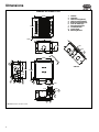
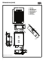
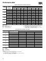
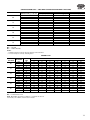
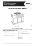
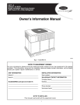
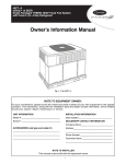
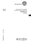
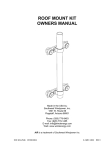
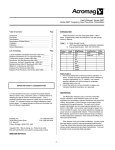
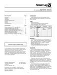
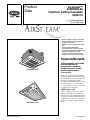
Product
Data
Airstream™
42WKN08-36
Hydronic Ceiling Cassettes
50/60 Hz
3/
4
to 3 Nominal Tons
(2.6 to 10.6 kW)
Hydronic ceiling cassette units offer:
• 6 chilled water cooling models to
properly match job
• Optional electric heat or hot water
coil
• Wall-mounted thermostat
• Installation cost savings through
use of exisiting piping and/or wiring
• Low noise level construction
• Optional microprocessor based
controller with infrared transmitter
a42-4013
Features/Benefits
UNIT SIZES 08-12
Ceiling cassette units make
each served area an
independent controlled
temperature zone to suit
diverse requirements.
Construction
Cases are constructed of lightweight
galvanized sheet steel with integral fan
mounting rails for added strength. Fire
resistant foam insulation (rated to
UL94 VO) is fitted internally to provide
both thermal and acoustic insulation.
The pearl-gray fascia is constructed
of high-impact polystyrene.
Chilled water coil
a42-4014
UNIT SIZES 18-36
© Carrier Corporation 2014
Units use large surface area coils positioned to optimize heat transfer and
airflow. Each coil is manufactured from
copper tubes with mechanically bonded aluminum fins and is circuited from
headers to ensure low water pressure
drops.
Form 42WKN-5PD
Features/Benefits (cont)
Fan
Condensate pump
The backward-curved, centrifugal
fans are statically and dynamically
balanced for quiet operation. Fan
impellers are made from either
aluminum or fire-retardant plastic
(UL94 VO) for lightweight and
corrosion-resistant operation. Enclosed multi-speed external rotor fan
motor allows good heat dissipation
and increased motor efficiency. Fans
come complete with thermal overload protection and sealed-for-life
lubricated bearings.
A condensate pump is fitted to carry
water out of the unit. The pump is
fixed to a mounting bracket which
can be withdrawn from the side of
the chassis and incorporates an inspection hole to allow a visual check
of the pump during operation. A
float switch is fitted to stop the cooling action should the pump become
blocked or fail.
Air vanes
Air outlet vanes are manufactured
from aluminum and covered with nylon flock to prevent condensation
from forming. Vanes are manually
adjustable on unit sizes 08,12 and
Filtration
Reusable wire framed filters are fitted
and may be vacuum cleaned.
driven by an electric motor on unit
sizes 18-36. Motorized air vanes can
be set to auto sweep or can be
stopped in a fixed position. Polystyrene blanking pieces are supplied
with cassette packing so that up to
two fascia discharge slots can be
blanked off.
Alarm interlock relay
Alarm interlock relay includes a relay
for unit failure notification. Normally
open/normally closed contacts are
available for field connection.
Table of contents
Page
Features/Benefits. . . . . . . . . . . . . . . . . . . . . . . . . . . . . . . . . . . . . . . . . . 1,2
Model Number Nomenclature . . . . . . . . . . . . . . . . . . . . . . . . . . . . . . . . . . 2
Physical Data . . . . . . . . . . . . . . . . . . . . . . . . . . . . . . . . . . . . . . . . . . . . . . 3
Options and Accessories . . . . . . . . . . . . . . . . . . . . . . . . . . . . . . . . . . . . . 4,5
Dimensions . . . . . . . . . . . . . . . . . . . . . . . . . . . . . . . . . . . . . . . . . . . . . . 6-8
Selection Procedure . . . . . . . . . . . . . . . . . . . . . . . . . . . . . . . . . . . . . . . . . 9
Performance Data . . . . . . . . . . . . . . . . . . . . . . . . . . . . . . . . . . . . . . . 10,11
Electrical Data . . . . . . . . . . . . . . . . . . . . . . . . . . . . . . . . . . . . . . . . . . . . 12
Typical Wiring Schematic . . . . . . . . . . . . . . . . . . . . . . . . . . . . . . . . . . . . 12
Controls . . . . . . . . . . . . . . . . . . . . . . . . . . . . . . . . . . . . . . . . . . . . . . . . 13
Guide Specifications . . . . . . . . . . . . . . . . . . . . . . . . . . . . . . . . . . . . . . 14,15
Model number nomenclature
42 SERIES HYDRONIC CEILING CASSETTES
42WKN
42WKN – Hydronic Cooling
Ceiling Cassette
Unit Size and Nominal Capacity
08 – 8 MBtuh
12 – 12 MBtuh
18 – 18 MBtuh
20 – 20 MBtuh
33 – 33 MBtuh
36 – 36 MBtuh
Supply Voltage
A – 115-1-60
B – 208-1-60
C – 230-1-60
H – 277-1-60
J – 110-1-50
K – 220-1-50
2
20
A
A
E
N
A
Filtration
A – Cleanable Filter
B – MERV 8 Filter
Heating Option
N – None
A – Electric Heat
B – Hot Water Heating Coil
Control
E – Electro-Mechanical Controls
M – Microprocessor Controls
Design Revision
A – Current Design
Physical data
42WKN UNIT SIZE
NOMINAL TONS
COOLING CAPACITY (Btuh)
DIMENSIONS/WEIGHTS
Height – Chassis/Fascia (in.)
(not additive)
Width – Chassis/Fascia (in.)
Depth – Chassis/Fascia (in.)
Weight – Chassis/Fascia (lb)
CHILLED WATER COIL
Type
Quantity
Face Area (sq ft)
Nominal Airflow (cfm)
High
Medium
Low
Discharge
Unit Water Volume (gal)
FAN
Type
Quantity
Diameter (in.)
Horsepower per fan (Hp)
CONNECTIONS (Sweat)
Chilled Water Inlet, OD (in.)
Chilled Water Outlet, OD (in.)
Condensate, ID (in.)
FILTRATION
Type
Quantity
Arrestance
Type
Quantity
Size (in.)
CONDENSATE PUMP
Maximum Head (in.)
Nominal Flow Rate (gpm)
HEATING OPTION
Electric Heating Capacity (kW)
Hot Water Heating Capacity (Btuh)
Hot Water Coil Connection, OD (in.) (Sweat)
BRANCH DUCT OPTION
Branch Duct Connections (quantity)
Branch Duct Diameter (in.)
Ducted Air Volume (cfm)
FRESH AIR OPTION
Fresh Air Connections (quantity)
Fresh Air Duct Diameter (in.)
Fresh Air Volume (cfm)
LEGEND
ID
N/A
OD
— Inside Diameter
— Not Applicable
— Outside Diameter
08
3/
4
6,601
12
1
11,091
18
1 1 /2
17,592
20
1 3 /4
19,087
33
2 1 /2
29,722
36
3
35,258
113/4 / 11/4
113/4 / 11/4
11 / 13/4
11 / 13/4
13 / 13/4
13 / 13/4
221/2 / 25
221/2 / 25
40 / 5
221/2 / 25
221/2 / 25
40 / 5
323/8 / 37
323/8 / 37
64 / 18
323/8 / 37
323/8 / 37
64 / 18
451/2 / 491/4
323/8 / 37
97 / 21
451/2 / 491/4
323/8 / 37
97 / 21
1
1.8
1
1.8
1
2.8
1
2.8
1
5.2
1
5.2
350
300
260
4-way
0.29
350
300
260
4-way
0.29
630
530
500
4-way
0.45
700
630
530
4-way
0.45
970
890
785
4-way
0.79
1160
970
890
4-way
0.79
1
12
1/
8
1
12
1/
8
1
15
1/
8
1
15
1/
8
2
14
1/
8
2
14
1/
8
5/
8
5/
8
3/
8
5/
8
5/
8
3/
8
7/
8
7/
8
3/
8
7/
8
7/
8
3/
8
7/
8
7/
8
3/
8
7/
8
7/
8
3/
8
1
80%
1
80%
3
80%
3
80%
1
12x12x1
1
12x12x1
3
12x24x1
3
12x24x1
30
0.1
30
0.1
30
0.1
30
0.1
30
0.1
30
0.1
1.5
13,799
5/
8
1.5
N/A
N/A
3.0
29,258
5/
8
3.0
30,946
5/
8
5.0
46,455
5/
8
5.0
51,600
5/
8
2
5
80
2
5
80
2
5
100
2
5
125
2
6
200
2
6
220
1-2
3
40
1-2
3
40
1-3
3
60
1-3
3
65
1-3
3
90
1-3
3
95
Finned Tube
Centrifugal
Cleanable Wire Framed
2
2
80%
80%
MERV 8 Throwaway
2
2
12x24x1
12x24x1
NOTES:
1. Cooling capacity based on 80 F dry bulb/67 F wet bulb indoor and
a 45 F entering/55 F leaving chilled water temperature.
2. Heating capacity based on water temperature of 180 F inlet /160 F
outlet and an air temperature of 70 F dry bulb.
3. Ducted air volume based on maximum air volume available
through one branch duct 6 ft long, with cassette fan(s) at high
speed and corresponding fascia aperture closed.
4. Fresh air volume based on maximum fresh air through all knockouts connected to one 10 ft long duct with fan at high speed.
3
Options and accessories
ITEM
Electro-Mechanical Controls
Microprocessor Controls
Electric Heat
Hot Water Coil
Hot Water Coil Freeze
Protection Sensor
Disconnect Switch
Chilled Water/Hot Water
Control Valve
Fresh Air Intake Duct Collar
Branch Duct Collars
Spare Filters
Shroud
Wall-Mounted Pendant
Thermostats
Aquastat
FACTORY-INSTALLED
OPTIONS
X
X
X
X
FIELD-INSTALLED
ACCESSORIES
X
X
X
X
X
X
X
X
X
X
Factory-installed options
Electro-mechanical controls include an electromechanical controller with a 24-v transformer. The controller requires a 24-v thermostat which can be supplied
loose for onsite wall mounting. Thermostat options include
cooling only or cooling and one stage auxiliary heat. Only
single fan speed thermostats can be used with this option.
Units are wired for medium speed. Wiring may be field
modified if high or low fan speed is desired.
Microprocessor controls include a custom designed
microprocessor fitted to the cassette to enable room conditions to be maintained at a user-defined set point. Communication to the controller is by a handheld infrared
transmitter or a wall-mounted 'pendant' transmitter. Each
type of transmitter includes a standard wall mounting
bracket.
The microprocessor allows five operating modes: fan
only, dry cooling, cooling only, heating only, and heating/
cooling with auto changeover for maximum versatility. A
temperature set point between 58 F and 90 F can also be
selected.
The microprocessor monitors indoor coil temperature
and return-air temperature. The receiver contains a self
diagnostic feature. When a low indoor coil temperature is
detected, the cooling action is stopped. If a sensor fails
then an alarm is displayed on the fascia-mounted receiver.
The microprocessor is controlled with either an infrared
transmitter or pendant transmitter, depending on the transmitter type selected at the time of order. A chip is factoryinstalled in the unit control board which operates exclusively with the type of transmitter selected.
The infrared or pendant transmitter is used to switch the
unit on/off, change temperature settings, fan speed, operating mode, and to toggle the motorized air sweep (where
fitted).
The microprocessor also has an built-in clock which can
be activated to enable the unit to be programmed with up
to two separate operating periods for the days of the week
(Mon-Fri). The clock provides ON/OFF unit operation and
is not a night set back or occupied/unoccupied control
function. Mon-Fri will operate as a 'block' of days and
cannot be programmed independently of one another.
Saturdays and Sundays can each be programmed with up
4
to two separate operating periods and are programmed
independently of the weekdays and each other.
A fascia-mounted receiver displays on/off, cool or heat,
and timer/alarm status.
Electric heat (single stage) includes fitted heating elements manufactured for maximum surface area and lower
working temperature for improved reliability. Thermal cutout protection switches are fitted to the electric heat circuit
to protect against overheating. The optional electric heating elements are available with the 208/220/230-v model
units only.
Hot water heat includes hot water heating coil factory fitted to the standard chilled water coil to provide heating.
The coil is manufactured from copper tubes with mechanically bonded aluminum fins. The hot water heat option is
not available on unit size 12.
Hot water coil freeze protection sensor is mounted to
prevent freezing of the hot water coil assembly. When the
sensor detects a freeze up condition, it will force the flow
control valve open and prevent the unit fan(s) from
running.
Disconnect switch (non-fused) is factory installed on
the control panel exterior and sized for the full load amperage of the unit to enable the unit to be disconnected from
the power supply prior to any maintenance.
Field-installed accessories
Chilled water/hot water control valve includes a
three-way, three-port diverting type valve or a two-way,
two-port control valve for control of chilled water or hot
water flow. Valve is supplied loose. Actuation is via a
24-v signal from the unit's electrical panel.
On a four-pipe system where two-way valves are specified, the chilled water valve will be a normally closed type.
The hot water valve will be a normally open type. Where
three-way valves are specified, the same type valve will be
supplied for both coils and should be installed normally
closed to the coil in the case of the chilled water coil and
normally open to the coil in the case of the hot water coil.
On a two-pipe changeover system where a two-way
valve is specified, a normally closed valve is supplied.
Where a three-way valve is specified, this should be
installed normally closed to the coil. In both cases, a pipe
mounted changeover thermostat can also be supplied to
monitor water supply temperature and allow action of the
valve.
Fresh air intake can be achieved by removing any number of the two or three (size dependent) fresh air knockouts
on the cassette chassis. Each individual knock-out accommodates 20 cfm of fresh air. A duct collar is available for
fastening to the unit to allow connection of a 3 in. flexible
duct.
Duct collars are available to allow connection of a 5 in.
or 6 in. (depending on unit size) flexible duct to the cassette. Branch ducting can be achieved by removing the
branch duct knockouts and connecting flexible ducting for
circulating a limited amount of conditioned air. For unit
sizes 08,12, a total of three knockouts are positioned on
three of the unit sides (one per side). For unit sizes 18-36,
a total of four knockouts are available and are arranged in
pairs along two of the unit sides (two per side).
NOTE: On the 08,12 size units, it is recommended that
only one of the three branch duct knockouts is utilized, due
to the small capacity of the unit.
Spare filters accessories include either a cleanable wire
mesh filter or a throwaway MERV 8 filter.
Shroud is a sheet metal cover used to cover unit housing
when the unit is not mounted in a drop or false ceiling. The
shroud is painted Sky White with a hammertone finish.
Wall-mounted pendant for communication to the
microprocessor controller replaces the standard infrared
remote control. This accessory requires the wall-mounted
pendant base be wired back to the unit. When this accessory is ordered, the unit will not ship with the infrared
remote.
Thermostats are available for use with the electromechanical controller. These thermostats operate with 24-v
power and are for wall mounting. Several options are available depending upon system type.
Aquastat is available for use with a 2-pipe heating/
cooling changeover system.
5
Dimensions
42WKN08 AND 42WKN12 UNIT
25 3/16
1.
2.
3.
4.
5.
6.
7.
8.
9.
10.
25 3/16
CW Inlet
CW Outlet
HW Coil Inlet (Optional)
HW Coil Outlet (Optional)
Branch Duct Opening (x3)
Fresh Air Intake (x2)
Pump Inspection Port
Condensate Drain
Control Panel
Mounting Bracket
1 11/16
10 11/16
1 1/8
2 3/4
5
2 3/4
9 13/16
11 1/4
6
22 1/2
A
19 9/16
5
O 5 3/16
A
11 5/16
VIEW A-A
22 1/2
22 15/16
4 11/16
3 11/16
7
2 5/8
8
8 13/16
9
7/8
10
12 9/16
19 1/2
1 7/16
6 1/2
5 1/8
3 3/4
3 3/8
a42-4319.eps
2 1/16
3
2 5/8
3 5/8
1
NOTE: Dimensions shown in inches.
6
2
4
42WKN18 AND 42WKN20 UNIT
1.
2.
3.
4.
5.
6.
7.
8.
9.
10.
37
37
CW Coil Inlet
CW Coil Outlet
HW Coil Inlet (Optional)
HW Coil Outlet (Optional)
Fresh Air Intake (x3)
Branch Duct Opening (x4)
Pump Inspection Port
Condensate Drain
Control Panel
Mounting Bracket
11/16
2 5/8
9 1/2
2 3/4
32 3/8
7 13/16
2 3/4
A
3 1/8
5
28 11/16
A
32 5/16
5 3/8
6
8 11/16
5 3/8
31 3/8
VIEW A-A
7
3 3/16
11 13/16
1 5/16
3
8 13/16
8
9
10
12 9/16
28 9/16
3
1 13/16
1
8 5/8
6
4 5/8
1 5/8
4 15/16
5 5/16
a42-4319
7 3/4
2
5
4
2 3/4
2 3/4
4 7/8
NOTE: Dimensions shown in inches.
7
Dimensions (cont)
42WKN33 AND 42WKN36 UNIT
37
1.
2.
3.
4.
5.
6.
7.
8.
9.
10.
CW Coil Inlet
CW Coil Outlet
HW Coil Inlet (Optional)
HW Coil Outlet (Optional)
Fresh Air Intake (x3)
Branch Duct Opening (x4)
Pump Inspection Port
Condensate Drain
Control Panel
Mounting Bracket
49 3/16
a42-4329
2 1/4
2 5/8
11 1/2
4 3/4
9 13/16
32 3/8
3 1/8
2 3/4
5
A
28 11/16
A
6
19 5/8
VIEW A-A
43 1/2
6 3/8
3 5/8
7
12 7/16
3 3/8
8 13/16
3
8
9
7/8
10
12 9/16
28 9/16
1 7/8
1
3
7 3/16
6
4 5/8
2 3/16
1 5/8
7 9/16
4 3/4 9 13/16
2
5
4
NOTE: Dimensions shown in inches.
8
2 3/4
2 3/4
4 7/8
Selection procedure (42WKN12 unit example)
I Determine job requirements.
Given:
Room Sensible Cooling Load . . . . . . . .8,200 Btuh
Room Total Cooling Load . . . . . . . . .11,000 Btuh
Entering-Air Temperature . . . . . . 80 F at 50% RH
Entering Water Temperature . . . . . . . . . . . . .45 F
Temperature Rise . . . . . . . . . . . . . . . . . . . . .10 F
Nominal Air Delivery . . . . . . . . . . . . . . . . 350 cfm
II Determine unit size and nominal cfm.
For an initial selection, choose a unit size that will
provide the required airflow (cfm). Refer to the
Physical Data table on page 3. At high speed, a
42WKN12 unit will provide 350 cfm.
III Determine total cooling capacity.
Refer to the cooling capacity table for 42WKN12
on page 10. Locate required entering dry bulb (edb)
and relative humidity (RH) conditions. Locate the
entering water temperature required. Under Total
Cooling (TC) column, a 42WKN12 unit at an entering-air temperature of 80 F dry bulb at 50% RH, an
entering water temperature of 45 F, and a water
temperature rise of 10 F, will provide 11,236 Btuh.
IV Determine sensible cooling capacity.
In cooling capacity table for 42WKN12, locate the
sensible cooling (SC) column and find that the
42WKN12 at the required conditions will provide
8,200 Btuh of sensible cooling at a water temperature rise of 10 F. The 42WKN12 will satisfy the job
requirements.
If additional SC were required, a larger unit or a
lower entering water temperature would be needed.
9
Performance data
CHILLED WATER UNIT COOLING CAPACITIES
42WKN
UNIT SIZE
ENTERING
DB AIR
TEMPERATURE (F)
at 50% RH
TC (Btuh)
72
75
80
72
75
80
72
75
80
72
75
80
72
75
80
72
75
80
5,236
6,528
10,037
8,723
10,831
14,435
13,728
17,478
24,588
14,810
18,956
26,569
23,570
29,100
41,598
27,054
33,895
47,991
08
12
18
20
33
36
DB
RH
SC
TC
—
—
—
—
CHILLED WATER ENTERING/LEAVING TEMPERATURE
40/50 F
45/55 F
Flow
Flow
Pressure
TC (Btuh)
SC (Btuh)
SC (Btuh)
(gpm)
(gpm)
Drop (psi)
5,156
1.1
2.4
3,999
3,999
0.8
5,989
1.3
3.5
4,729
4,729
1.0
7,529
2.0
7.6
7,026
6,107
1.4
7,261
1.8
1.9
5,623
5,623
1.1
8,173
2.2
2.7
7,502
6,604
1.5
9,644
2.9
4.6
11,236
8,200
2.3
12,126
2.8
1.9
9,295
9,295
1.9
13,840
3.5
2.8
11,447
10,853
2.3
16,659
4.9
5.1
18,432
13,900
3.7
13,098
3.0
2.1
10,103
10,103
2.0
14,985
3.8
3.3
12,341
11,716
2.5
18,022
5.3
5.9
19,971
15,041
4.0
20,321
4.7
3.5
15,695
15,695
3.2
5.1
19,912
18,365
4.0
22,928
5.8
28,029
8.3
9.6
30,595
23,129
6.1
23,385
5.4
4.5
18,066
18,066
3.6
26,690
6.8
6.7
22,721
21,074
4.6
32,334
9.6
12.5
35,934
26,916
7.2
LEGEND
Dry Bulb
Relative Humidity
Sensible Cooling Capacity
Total Cooling Capacity
Pressure
Drop (psi)
1.5
2.0
4.0
0.9
1.4
2.9
0.9
1.4
3.1
1.1
1.5
3.6
1.7
2.7
5.6
2.2
3.3
7.5
NOTES:
1. All duties based on high fan speed except where stated otherwise.
2. Cooling capacities are gross. Do not include fan motor gains.
3. Pressure drops are coil only (excludes valves).
4. Hot water duties on chilled water units fitted with additional,
optional hot water coil. See data on next page.
HOT WATER COIL HEATING CAPACITIES
42WKN UNIT SIZE
ENTERING DB AIR
TEMPERATURE (F) at 50% RH
08
12
18
20
33
36
50
60
70
50
60
70
50
60
70
50
60
70
50
60
70
50
60
70
Heating Capacity (Btuh)
16,819
15,292
13,799
N/A
N/A
N/A
35,763
32,480
29,258
37,938
34,401
30,946
55,683
51,120
46,555
62,005
56,762
51,600
LEGEND
DB — Dry Bulb
N/A — Not Applicable
RH — Relative Humidity
NOTES:
1. All duties based on high fan speed except where stated otherwise.
2. Pressure drops are coil only, excluding valves.
3. Hot water duties based on units fitted with additional, optional hot water coil.
4. Hot water coil not available on size 42WKN12.
10
HOT WATER INLET 180F/160F
Flow Rate (gpm)
1.8
1.6
1.4
N/A
N/A
N/A
3.7
3.4
3.1
4.0
3.6
3.2
5.8
5.3
4.9
6.5
5.9
5.4
Pressure Drop (psi)
3.9
3.3
2.7
N/A
N/A
N/A
3.4
2.9
2.4
3.7
3.2
2.7
4.0
3.5
3.0
4.8
4.1
3.5
CHILLED WATER UNIT — TWO-PIPE CHANGEOVER HEATING CAPACITIES
42WKN UNIT SIZE
ENTERING DB AIR
TEMPERATURE (F) at 50% RH
50
60
70
50
60
70
50
60
70
50
60
70
50
60
70
50
60
70
08
12
18
20
33
36
Heating Capacity (Btuh)
28,389
25,903
23,605
33,471
30,715
27,995
60,388
55,127
49,706
65,350
59,887
54,118
99,476
91,494
82,986
114,225
105,132
95,896
HOT WATER INLET 180F/160F
Flow Rate (gpm)
3.0
2.7
2.5
3.5
3.2
2.9
6.3
5.8
5.2
6.8
6.3
5.7
10.4
9.6
8.7
11.9
11.0
10.0
Pressure Drop (psi)
11.0
9.4
8.0
4.6
4.0
3.4
5.7
4.8
4.0
6.5
5.6
4.7
10.1
8.8
7.4
13.0
11.2
9.5
LEGEND
DB — Dry Bulb
RH — Relative Humidity
NOTES:
1. All duties based on high fan speed except where stated otherwise.
2. Pressure drops are coil only, excluding valves.
SOUND DATA
42WKN
UNIT SIZE
08
12
18
20
33
36
FAN SPEED
SPL
dBA
High
Med
Low
High
Med
Low
High
Med
Low
High
Med
Low
High
Med
Low
High
Med
Low
29
26
22
35
32
29
43
39
38
46
43
39
48
44
42
52
48
45
125 Hz
37
34
31
42
38
37
41
39
38
43
41
39
51
50
49
54
51
50
SOUND PRESSURE FREQUENCY SPECTRUM, dB
250 Hz
500 Hz
1000 Hz
2000 Hz
4000 Hz
37
33
29
21
14
34
30
24
15
12
29
25
17
8
10
41
38
35
28
21
39
36
32
24
16
37
33
29
21
14
45
38
40
33
25
41
35
36
27
19
40
34
34
25
18
47
40
43
37
29
45
38
40
33
25
41
35
36
27
19
49
46
42
34
22
46
43
38
28
18
44
41
36
25
17
54
50
46
41
27
49
46
42
34
22
47
44
39
31
19
8000 Hz
10
10
8
12
10
10
17
16
16
19
17
16
19
17
16
24
19
18
LEGEND
SPL — Sound Pressure Level
NOTE: Overall SPL measured at a distance of 5 ft below the fascia in
free field, dry coil conditions, referenced to 2 x 10⁵Pa.
11
Electrical data
42WKN
NOMINAL CAPACITY
(Digit 4,5)
PERFORMANCE (WITH ELECTRIC HEAT)*
SUPPLY VOLTAGE
(Digit 6)
PERFORMANCE (NO ELECTRIC HEAT)
FLA
MCA
Recommended
Fuse Size
FLA
MCA
Recommended
Fuse Size
—
—
—
0.70
0.88
15
B: 208-60-1
6.25
7.81
15
C: 230-60-1
6.87
8.59
15
0.35
0.44
15
K: 220-50-1
6.59
8.24
15
H: 277-60-1
—
—
—
0.29
0.36
15
—
—
—
1.10
1.38
15
B: 208-60-1
12.35
15.44
20
C: 230-60-1
13.59
16.99
20
0.55
0.69
15
K: 220-50-1
13.03
16.29
20
H: 277-60-1
—
—
—
0.46
0.58
15
—
-—
-—
1.92
2.40
15
0.96
1.20
15
0.80
1.00
15
A: 115-60-1
J: 110-50-1
08 and 12
Small Chassis
A: 115-60-1
J: 110-50-1
18 and 20
Medium Chassis
A: 115-60-1
J: 110-50-1
33 and 36
Large Chassis
B: 208-60-1
20.68
25.85
30
C: 230-60-1
22.76
28.45
30
K: 220-50-1
21.81
27.26
30
H: 277-60-1
—
—
—
LEGEND
FLA — Full Load Amps
MCA — Minimum Circuit Amps
*Standard unit fitted with optional electric heating elements. Available
with 208/220/230-v model units only.
Typical wiring schematic
NOTE: Refer to Installation and Operation manual for
wiring schematic.
12
Controls
Sequence of operation
Electro-mechanical controls — A 24-v signal from the
thermostat to terminal G supplies power to the blower
motor(s), condensate pump and vane motor (if equipped).
A toggle switch on the control box can be used to switch
the oscillating vanes on or off. The condensate pump will
run continuously, as long as the blower is energized. A call
for heating, at terminal W, or cooling, at terminal Y, will
energize the water valve actuator and allow water to flow
through the cassette coil. When the call for heating or cooling is satisfied the valve will close.
If the temperature drops below the set point of the coil
freezestat, the water valve with automatically open to circulate water through the coil.
If the condensate float switch detects a high level of
water in the condensate tray, the switch will open, activate
the condensate pump and disable the heating/cooling signal until the water level drops down to normal.
Microprocessor controls — The PCB (printed circuit
board) microprocessor control board relays control the
operation of the indoor-fan motor, outdoor-fan motor,
compressor and electric heater (if fitted), to maintain room
conditions at a user-defined set point.
Temperature settings, fan speeds and other control
functions can be changed by the infrared transmitter or
optional pendant. The controller PCB provides the following input/output facilities:
Inputs
T1 Return Air Temperature Sensor: 50k at 77 F.
T3 Indoor Coil Temperature Sensor: 50k at 77 F.
Outputs
Indoor fan motor — The controller will switch a combination of three, 10-amp, 230-vac (3 speed settings) resistive
rated relays to deliver the selected indoor fan speed.
Condensate pump — Activated when unit is in cooling
mode.
Vane motor — A 10-amp, 230-vac resistive rated relay
switches the vane motor on when Air Sweep is selected
(units sizes 18-36 only).
Electric heat — A 30-amp, 230-vac resistive rated relay
switches the electric heater on when required.
Indoor fan operation
The indoor fan will run continuously at the most recently
set speed or will alter the speed according to the room
temperature conditions when set to Auto. The indoor fan
will continue to run until the unit is turned off by the user or
by a preset time setting. When the unit is turned off during
heating, the indoor fan will continue to run for approximately 2 minutes, this helps to dissipate residual heat from
the electric heaters.
Boost heat
The electric heat relay can be used to initiate either low
watts density electric heating (optional) or low pressure hot
water heating (optional). The boost heat will be activated
when the room temperature falls to more than 8º F below
set point. Hysteresis of 2º F will be applied to prevent
“hunting.” The boost heat facility is automatically enabled
or disabled by selecting non heat pump (Jumper 2 open).
Temperature control
The controller will switch heating or cooling loads in order
to maintain the temperature set point. The deadband is
programmed to 4º F. Under normal operation, cooling or
heating will be activated at the limits of the deadband and
will continue to operate until set point is achieved.
The temperature set point can be adjusted between
58 and 90 F in 2º F increments.
Power failure
The controller will auto restart in its previous mode of
operation after a power failure. When power is restored,
the controller will revert to its last operating mode, e.g., if
the controller was turned on before power fail, after power
is restored the controller will automatically turn on. Alternatively, if the controller was turned off before power fail,
the controller will remain off after power is restored.
Electric heater overheat protection
In the event of an auto reset overheat cutout, the electric
heater will be switched off until the temperature drops sufficiently for the auto cutout to reset itself.
Master/slave operation
The network option allows for one master unit and up to
19 slave units to be interconnected using a twin twisted
pair screened cable to create a network.
The master/slave operation has been programmed to
operate the units in the following manner:
When the master unit receives a transmission from the
transmitter, the transmitter settings are provided to all units
on the network.
Slave units do NOT monitor the return-air temperature
but rely instead on the master unit to monitor return-air
temperature and make all control decisions. Slave units will
mimic the operation of the master unit and will cool, heat,
switch on, switch off etc., with the master.
At all times, the slave units will follow the usual method
of operation regarding alarms and will act accordingly.
When a master unit experiences an alarm, it will act in the
usual manner while maintaining instruction to slave units to
operate normally. The exception to this is when the master
unit experiences a return air sensor failure. Because the
master unit cannot control correctly, it will instruct the
slave units to revert to stand-alone operation.
In the event of the network cable being severed or communications between master and slaves being lost for any
reason, the slave units will revert to stand-alone control
after six minutes without instruction from the master. During this time, the slaves will monitor the return air temperature themselves and will make their own control decisions
based upon the last set of transmitter settings received
from the master unit.
13
Guide specifications
Commercial Hydronic Cassette Fan Coil
HVAC Guide Specifications
Size Range: ¾ to 3 Tons
7,000 to 36,000 Btuh,
Nominal Cooling
15,000 to 66,000 Btuh,
Nominal Heating
Carrier Model Number: 42WKN
Part 1 — General
1.01 SYSTEM DESCRIPTION
Indoor, in-the-ceiling mounted, chilled or hot water
coil, to be matched with a commercial chiller, water
source heat pumps, or hot water boiler (180 F
maximum).
1.02 QUALITY ASSURANCE
Base unit shall be certified by UL (Underwriters Laboratories). Each coil shall be factory tested for leakage at 325 psig air pressure with coil submerged in
water. Insulation and adhesive shall meet NFPA-90A
(National Fire Protection Association) requirements
for flame spread and smoke generation. Insulation
shall be rated to UL94 VO. All equipment wiring
shall comply with NEC (National Electrical Code)
requirements.
1.03 DELIVERY, STORAGE, AND HANDLING
Unit shall be stored and handled per manufacturer’s
instructions.
1.04 WARRANTY (One year on parts).
Part 2 — Products
2.01 EQUIPMENT
A. General:
Indoor, downward discharge 2 or 4-pipe low-profile
in-ceiling fan coil. Units shall come complete with
cooling coil or hot water coil (4-pipe systems only),
fan, fan motor, piping connectors, electrical controls, condensate pump, and hanging brackets.
B. Unit Cabinet:
1. Cabinet shall be constructed of galvanized sheet
steel. Cabinet shall have filter tracks and cleanable filters which shall be accessible from below.
Adjacent room cooling to be provided by a simple knockout in the cabinet side panel, and cabinet shall have provisions to accommodate a
limited amount of ductwork, if desired.
2. Fan shall be a centrifugal, direct-drive blower
type with air intake in center of the unit and discharge on the perimeter. Air louvers shall be
adjustable for 2, 3 or 4-way discharge. Air outlet vanes shall be fully insulated aluminum to
prevent condensation from forming. Vanes
shall be manually adjustable on unit sizes
08,12, but shall be driven by an electric motor
for unit sizes 18-36.
3. Fascia shall be constructed of high impact
polystyrene.
14
C. Coil:
1. Standard base unit shall be equipped with a
cooling coil for installation in a 2-pipe system.
Additional coil depth and circuiting shall be provided for installation in a 4-pipe system.
2. Heating coils are single row, independently circuited coils specifically designed for hot water
application. Heating coil is located downstream
from cooling coil.
3. Coils shall have ½-in. copper tubes, aluminum
fins bonded to the tubes by mechanical expansion, and a working pressure of 325 psig.
4. Each coil shall have a manual air vent on upper
connection, a drain port on the lower connection.
D. Motors:
Motor shall be enclosed and with thermal overload
protection, sealed for life lubricated bearings, and
external rotor allowing good heat dissipation. Fan
motor shall be 3-speed.
E. Controls:
Controls shall be 24-v, and shall be easily operated
by the user from a wall-mounted thermostat. A
normally closed float control shall be in the condensate sump to shut unit down in case of pump
malfunction.
F. Alarm Interlock Relay:
Alarm interlock relay shall include a relay for
unit failure notification. Normally open/normally
closed contacts are available for field connection.
G. Filters:
Unit shall have a filter track with factory-supplied
cleanable filters or MERV 8 disposable filters.
H. Electrical Requirements:
Unit shall operate on a 115-v, 208-v, 230-v or
277-v 60 Hz power supply or on 110-v or 220-v 50
Hz power supply as specified on the equipment
schedule.
I. Operating Characteristics:
A one-coil unit installed in a 2-pipe system shall be
capable of providing cooling as specified by the
operating mode of the central water supply system.
A double-circuit coil unit installed in a 4-pipe system
shall be capable of providing sequenced heating and
cooling.
J. Special Features:
1. Fresh Air Intake Kit:
The fresh air intake kit shall include duct collars
for connection to the unit.
2. Duct Collars:
Duct collars shall be available to allow connection of a 5 in. or 6 in. (depending on unit size)
flexible duct to the cassette.
3. Thermostat:
The thermostat shall be commercial grade to
control unit operation and shall provide single
speed fan capability. Automatic changeover
from cooling or heating shall be provided
(4-pipe systems only).
4. Motorized Valve Accessory:
The motorized valve shall be a two-position,
spring return two or three-way valve.
5. Microprocessor Control:
a. The microprocessor control shall include a
custom designed microprocessor fitted to the
cassette to enable room conditions to be
maintained at a user defined set point.
b. Microprocessor controller shall allow automatic control of fan speed based on demand
in space. The controller, either an infrared
transmitter or pendant transmitter, also
allows programming of a weekly operating
schedule.
6. Electric Heat:
Single-stage electric heat shall include fitted
heating elements manufactured for maximum
surface area and lower working temperature for
improved reliability. Thermal cutout protection
switches are fitted to the electric heat circuit to
protect against overheating. The optional electric heating elements are available with the
208/220/230-v model units only.
7. Hot Water Coil Freeze Protection Sensor:
The freeze protection sensor shall be available
for mounting to prevent freezing of the hot
water coil assembly. When the sensor detects a
freeze up condition, it will force the flow control
valve open and prevent the unit fan(s) from
running.
8. Disconnect Switch:
The non-fused disconnect switch shall be factory mounted on the exterior of the control
panel and sized for the full load amperage of
the unit to enable the unit to be disconnected
from the power supply prior to any
maintenance.
9. Shroud:
A shroud shall be available as a sheet metal
cover used to cover unit housing when the unit
is not mounted in a drop or false ceiling. The
shroud is painted Sky White with a hammertone finish.
10. Wall-Mounted Pendant:
A wired, wall-mounted pendant for communication to the microprocessor controller shall be
available to replace the standard infrared
remote control.
11. Aquastat:
An aquastat shall be available for use with a
2-pipe heating/cooling changeover system.
15
Carrier Corporation • Syracuse, New York 13221
10-14
Manufacturer reserves the right to discontinue, or change at any time, specifications or designs without notice and without incurring obligations.
Pg 16
Catalog No. 04-52420017-01
Printed in U.S.A.
Form 42WKN-5PD
Replaces: 42WKN-4PD