
1
Wireless File Transmitter WFT-E4 II Y P O Before using the WFT-E4 II with an EOS 5D Mark II, make sure the camera firmware is Ver. 1.2.0 or later. For details, contact a Canon Service Center. C To comply with local radio wave regulations, Canon offers four region-specific versions of the transmitter (WFT-E4 IIA, E4 IIB, E4 IIC, and E4 IID) in various areas around the world (p.8). For convenience, we refer to the product in this manual simply as “the transmitter,” without reference to versions A, B, C, or D. E INSTRUCTION MANUAL Introduction The Wireless File Transmitter WFT-E4 II is an accessory for EOS 5D Mark II camera. It gives the camera wireless and wired LAN functionality and adds a USB port, enabling the following operations. It also includes a vertical-grip shutter button for convenience in vertical shooting. Wireless and Wired LAN Functions FTP Transfer Transfer images to an FTP server Y P O EOS Utility Use EOS Utility to capture, view, and download images remotely C WFT Server Use a web browser to capture, view, and download images remotely Linked Shooting Wirelessly trigger shooting by slave cameras linked to a master camera 2 Introduction Functions When Connected via USB External Media Record or backup images onto external media GPS C Connected by a USB cable Y P O Connected via Bluetooth Add the latitude, longitude, altitude, date and time, and other shooting information to images 3 Conventions Used in this Manual These instructions should be followed only after your wireless or wired LAN and FTP server settings are complete. For details on configuring these settings, refer to the documentation provided with the respective equipment. Terms in brackets [ ] indicate button or icon names or other software elements. Brackets also denote camera menu items. Page numbers in parentheses indicate where you can find additional information. Instructions on camera operations should be followed only after you have read the Camera Instruction Manual and are familiar with operating the camera. Sections of this manual labeled with the following symbols contain information of the corresponding nature. : Warnings to avoid potential problems are labeled with a caution symbol. : Supplemental information is labeled with a note symbol. C Y P O Windows is a trademark or registered trademark of Microsoft Corporation in the United States and other countries. Macintosh is a registered trademark of Apple Corporation in the United States and other countries. Wi-Fi is a registered trademark of the Wi-Fi Alliance. Wi-Fi Certified, WPA, WPA2, and the Wi-Fi Certified logo are trademarks of the Wi-Fi Alliance. WPS as used on camera settings screens and in this manual signifies Wi-Fi Protected Setup. UPnP is a trademark of the UPnP Implementers Corporation. Bluetooth and the Bluetooth logos are trademarks owned by Bluetooth SIG, Inc. All other corporate and brand names in this manual are trademarks or registered trademarks of their respective owners. Using the transmitter for remote image transfer, capture, or viewing requires adequate knowledge of configuring your wireless or wired LAN and FTP server. Canon cannot provide support for configuring wireless or wired LANs or FTP servers. Note that Canon cannot be held liable for any loss or damage to the transmitter from erroneous network or FTP server settings. In addition, Canon cannot be held liable for any other loss or damage caused by use of the transmitter. 4 Chapter List Introduction 2 1 Basic Network Settings 19 2 Transferring Images to an FTP Server 33 3 Remote Capture Using EOS Utility 47 4 Remote Capture Using WFT Server 53 5 Linked Shooting 6 Managing Settings Information 69 7 Using External Media 75 8 Using GPS Devices 87 9 Troubleshooting 95 10 Reference C Y P O 65 113 5 Contents Introduction 2 Conventions Used in this Manual ...................................................................................................... 4 Chapter List........................................................................................................................................ 5 Contents............................................................................................................................................. 6 Areas of Use and Restrictions ........................................................................................................... 8 Safety Warnings............................................................................................................................... 10 Nomenclature................................................................................................................................... 11 Attaching to the Camera .................................................................................................................. 13 Vertical Shooting Controls ............................................................................................................... 14 Installing and Removing the Battery ................................................................................................ 15 Using a Household Power Outlet..................................................................................................... 17 Subsequent Organization of This Manual........................................................................................ 18 1 2 Basic Network Settings 19 Getting Ready .................................................................................................................................. Displaying the Connection Wizard ................................................................................................... Selecting the Communication Method and LAN Type ..................................................................... Using the Wizard to Establish a Connection.................................................................................... WPS Connections (PBC Mode) ....................................................................................................... WPS Connections (PIN Mode) ........................................................................................................ Configuring Network Settings .......................................................................................................... 20 21 22 25 27 28 29 Transferring Images to an FTP Server 33 Configuring FTP Communication Settings....................................................................................... Automatic Image Transfer After Each Shot ..................................................................................... Transferring Images Individually ...................................................................................................... Batch Transfer ................................................................................................................................. Checking Image Transfer History .................................................................................................... Viewing Transferred Images ............................................................................................................ 34 36 38 40 44 45 Remote Capture Using EOS Utility 47 C 3 Y P O Configuring EOS Utility Communication Settings ............................................................................ 48 Using EOS Utility ............................................................................................................................. 51 4 6 Remote Capture Using WFT Server 53 Configuring WFT Server Communication Settings .......................................................................... Displaying WFT Server .................................................................................................................... Viewing Images................................................................................................................................ Remote Capture [Camera control] ................................................................................................... Remote Capture [Simple control]..................................................................................................... Remote Capture............................................................................................................................... 54 56 57 59 62 63 Contents 5 Linked Shooting 65 Setting Up Linked Shooting ............................................................................................................. 66 Arranging the Slave Cameras.......................................................................................................... 68 6 Managing Settings Information 69 Checking Settings ............................................................................................................................ 70 Changing Settings............................................................................................................................ 71 Saving and Loading Settings ........................................................................................................... 73 7 8 Using External Media 75 Connecting External Media.............................................................................................................. Choosing Recording Media When Shooting .................................................................................... Using Together With a CF Card....................................................................................................... Backing Up on External Media......................................................................................................... 76 79 81 82 Using GPS Devices 87 Connecting GPS Devices with a USB Cable ................................................................................... 88 Connecting GPS Devices via Bluetooth........................................................................................... 91 9 Troubleshooting Y P O 95 Responding to Error Messages ....................................................................................................... 96 Wireless LAN Notes....................................................................................................................... 110 Checking Network Settings............................................................................................................ 111 10 Reference C 113 Creating and Registering Captions ................................................................................................ 114 Specifications................................................................................................................................. 115 Index .............................................................................................................................................. 125 7 Areas of Use and Restrictions To comply with local radio wave regulations in various areas around the world, Canon offers four region-specific versions of the transmitter (WFT-E4 IIA, E4 IIB, E4 IIC, and E4 IID) as described below. Please do not use your model (version) of transmitter in regions it was not designed for. For information on other areas where the transmitter can be used, contact a Canon Service Center. Model (Version) Area of Use WFT-E4 IIA United States, Canada, Singapore, and Hong Kong Japan, France, Italy, Germany, United Kingdom, Belgium, the Netherlands, Luxembourg, Ireland, Denmark, Greece, Spain, Portugal, Austria, Finland, Sweden, Poland, Hungary, WFT-E4 IIB Romania, Bulgaria, Czech Republic, Slovakia, Slovenia, Estonia, Latvia, Lithuania, Cyprus, Malta, Iceland, Norway, Switzerland, Liechtenstein, Australia, New Zealand, Russia, and Hong Kong WFT-E4 IIC Mainland China and Hong Kong WFT-E4 IID Can be used in all areas noted above Wireless LAN Specification and Supported Channels 36 – 64 ch IEEE 802.11a 149 – 165 ch IEEE 802.11b/g 1 – 11 ch IEEE 802.11a 36 – 64 ch 100 – 140 ch IEEE 802.11b/g 1 – 13 ch IEEE 802.11a IEEE 802.11b/g IEEE 802.11a IEEE 802.11b/g 149 – 161 ch 1 – 13 ch Not supported 1 – 11 ch Y P O In France, outdoor use is prohibited. In mainland China, outdoor use requires a permit in some areas. C IEEE 802.11a Restrictions When IEEE 802.11a wireless networking is used, channels in gray in the following table cannot be used. These restrictions are established by local regulations, which must be upheld. The transmitter can be used on channels in blue. Regarding channels in yellow, some restrictions apply. Refer to the footnotes. Indoors WFT-E4 IIA Outdoors Indoors WFT-E4 IIB Outdoors Wireless LAN Connection Method Infrastructure Ad hoc Infrastructure Ad hoc Infrastructure Ad hoc 36 – 48 36 – 48 36 – 48 36 – 48 36 – 48 36 – 48 52 – 64 52 – 64 52 – 64 52 – 64 52 – 64 52 – 64 149 – 165 149 – 165 149 – 165 149 – 165 100 – 140 100 – 140 Infrastructure 36 – 48 36 – 48 52 – 64*J 52 – 64 100 – 140 Ad hoc Channel 149 – 161*C *J: In Japan, outdoor use on channels 52 – 64 is prohibited. *C: In mainland China, outdoor use requires a permit in some areas. WFT-E4 IIC 8 100 – 140 Areas of Use and Restrictions The following actions may be punishable under law. Disassembling or modifying the transmitter, or removing the certification label on it. Do not use the transmitter near other devices that emit radio waves, such as medical equipment or electronic devices. The transmitter may interfere with operation of these devices. Use the transmitter only with a compatible EOS DIGITAL camera. Using it with incompatible cameras may cause malfunction, accidents, and other problems not covered under warranty. Use the transmitter as a wireless or wired LAN device as described in this instruction manual. If you use the transmitter for any other purpose, Canon cannot be held liable for any loss or damage that may occur. C Y P O 9 Safety Warnings The following precautions are intended to prevent harm to you and others as well as damage to equipment. Become familiar with the precautions before using the transmitter to ensure correct and safe operation. Be sure that you fully understand the safety precautions contained in the instruction manuals for the battery, charger, and AC Adapter Kit before using them. Warning Preventing Serious Injury or Death To prevent fire, excessive heat, chemical leakage, or explosion, follow these safety guidelines. • Do not insert metallic objects between electrical contacts of the transmitter, accessories, or connecting cables. Do not use the transmitter where there is flammable gas. There is a risk of explosion or fire. If the transmitter is dropped and internal parts are exposed, do not touch the exposed parts. There is a risk of electrical shock. Do not disassemble or modify the transmitter. High-voltage internal parts may cause electrical shock. Do not store the transmitter in dusty or humid places. There is a risk of fire or electrical shock. Before using the transmitter on board airplanes or in hospitals, make sure use is permitted. Electromagnetic waves emitted by the transmitter may interfere with instrumentation or medical equipment. Caution Preventing Injury or Equipment Damage Do not leave the transmitter inside a vehicle in hot weather or near a heat source. The transmitter may become hot and cause burns if touched. Do not cover or wrap the transmitter with a cloth. This may trap heat inside, posing a risk of case deformation or fire. Do not use paint thinner, benzene, or other organic solvents to clean the transmitter. This poses a risk of fire and may be hazardous to your health. Y P O If the product malfunctions, becomes damaged, or requires repair, contact your dealer or the nearest Canon Service Center. C Handling Precautions The transmitter is a precision instrument. Do not drop it or subject it to shock. The transmitter is not waterproof. Do not use it underwater. Wipe off any moisture with a clean, dry cloth. If the transmitter has been exposed to salty air, wipe it with a clean damp cloth after wringing it out to remove excess water. Never leave the transmitter near any equipment that generates a strong magnetic field, such as magnets or electric motors. Do not leave the transmitter in excessive heat, such as in a vehicle in direct sunlight. High temperature may damage the transmitter. Do not wipe the transmitter using cleaners containing organic solvents. If the transmitter becomes difficult to clean, take it to the nearest Canon Service Center. To avoid corrosion, do not store the transmitter where there are strong chemicals, such as in darkrooms or chemical labs. 10 Nomenclature Protective cover Positioning pin Battery compartment cover release lever Terminal cap holder * Turn the attachment knob to remove. AE lock/FE lock/ Index/Reduce button Attachment knob Tripod screw Positioning pin AF start button Terminal DC coupler cord notch USB port C Ethernet RJ-45 port Y P O LCD panel AF point selection/ Magnify button Battery lock lever Battery compartment Battery compartment cover <LAN> Network lamp <USB> USB lamp Shutter button Main dial Vertical-grip <ON/OFF> switch Tripod socket Hand strap mount 11 Nomenclature LCD panel CF card loading indicator External media selection mark External media connection indicator CF card selection mark Wired LAN connection Wireless LAN connection Recording quality at [Rec. separately] setting Battery level indicator Y P O Waterproof/dustproof USB cap C * Attach this cap before connecting the USB cable in rainy weather or under other adverse conditions. 12 Attaching to the Camera Load a charged battery into the camera. Before attaching the transmitter to the camera, set the camera’s power switch to <OFF>. The transmitter does not have a power switch. It is turned on and off in conjunction with the camera’s power switch. Before removing the transmitter, set the camera’s power switch to <OFF>. 1 Remove the terminal cap from the camera. 2 Attach the transmitter. Peel off the terminal cap on the camera bottom to remove. Attach the removed terminal cap to the transmitter’s terminal cap holder. C Y P O As shown in the figure, align the transmitter and the camera, and turn the attachment knob to attach to the camera. 13 Vertical Shooting Controls Setting the vertical-grip <ON/OFF> switch to <ON> enables the vertical-grip shutter button and other controls. These controls for shooting can still be used even when batteries are not loaded in the transmitter. Attaching the Hand Strap E1 The Hand Strap E1 (sold separately) is attached as shown in the figure. 1 4 2 3 Y P O 5 C 6 After the hand strap is attached, check that all the slack at the buckle is removed and that there is no looseness at the buckle even when pulled tight. 14 Installing and Removing the Battery Use one Battery Pack LP-E6 to power the transmitter. When replacing the transmitter’s battery, be sure to first set the camera’s power switch to <OFF> before opening the transmitter’s battery compartment cover. In particular, if the battery compartment cover is opened without setting the camera’s power switch to <OFF> while external media, GPS device or Bluetooth unit is still connected, you will need to reestablish the connection to the external media, GPS device, or Bluetooth unit. The transmitter’s battery is not included. Customers who do not have one should purchase it separately. Installing the battery 1 Open the cover. 2 Insert the battery. Slide the lever to open the cover. C 3 Y P O Insert from the side with battery contacts. Insert the battery all the way until it locks into place. Close the cover. Press the cover up until it clicks into place. 15 Installing and Removing the Battery Battery check The remaining battery power is displayed when the camera is turned on. A blinking battery icon ( ) indicates that the battery will be depleted soon. Icon Level (%) 100 – 70 69 – 50 49 – 20 19 – 10 Number of images that can be transferred 9–1 0 Approx. number of images LAN At Normal Temperature (23°C / 73°F) At Low Temperature (0°C / 32°F) Wireless LAN 2300 2200 Wired LAN 3000 2600 Y P O Using a fully charged LP-E6. The number of images that can be transferred is nearly the same at normal temperature (23°C / 73°F) and low temperature (0°C / 32°F). When automatic transfer is performed during shooting of an image of approx. 6 MB under conditions based on the CIPA (Camera & Imaging Products Association) test standards. Fewer images can be transferred when transferring images over a wireless LAN. Fewer images can be transferred when using bus-powered external media or GPS devices, or when using Bluetooth units. C Removing the battery 16 1 Open the cover. 2 Remove the battery. Slide the lever to open the cover. Press the battery lock lever in the direction of the arrow to unlock, and then unload the battery. To prevent a short-circuit, be sure to always attach the protective cover to the battery. Using a Household Power Outlet When the AC Adapter Kit ACK-E6 (sold separately) is used, a household power outlet can be used to power the camera without worrying about the battery level. 1 Connect the DC coupler plug. 2 Connect the power cord. 3 Insert the DC coupler. Connect the DC coupler plug to the socket of the AC adapter. Connect the power cord as shown. Insert the plug into the outlet. After usage, unplug from the outlet. Y P O Open the cover, and insert the DC coupler firmly until the lock position. 4C Close the cover. Pass the cord through the groove while opening the cap of the DC coupler cord notch, and then close the cover. Do not connect or disconnect the power cord while the camera’s power switch is set to <ON> or < >. 17 Subsequent Organization of This Manual Click one of the following chapter titles to view the corresponding page. 1 Basic Network Settings (p.19) 2 Transferring Images to an FTP Server (p.33) 3 Remote Capture Using EOS Utility (p.47) 4 Remote Capture Using WFT Server (p.53) 5 Linked Shooting (p.65) 6 Managing Settings Information (p.69) Y P O 7 Using External Media (p.75) C 8 Using GPS Devices (p.87) 18 Basic Network Settings Y P O Complete the basic network settings by following transmitter connection instructions on the camera menu screen. C 19 Getting Ready [FTP trans.], [EOSUtility], [WFTserver] The connection instructions help you follow the steps to connect the transmitter to an existing wireless or wired LAN. To connect to a wireless LAN, prepare the wireless LAN terminal (wireless LAN access point or wireless LAN adapter) and computer in advance so that they are ready for you to connect the transmitter to the wireless network. When configuring the basic network settings, bring the transmitter within 3 m / 9.8 ft. of the wireless LAN terminal. To connect to a wired LAN, use a LAN cable to connect the transmitter and computer. Set the transmitter for connection to the wired network. Wireless Transmission of Movie Individual movie files are large, and wireless file transmission takes some time. When setting up an environment for stable transmission to the wireless LAN terminal, refer to the information on page 110. [LinkedShot] Y P O Set up two or more EOS 5D Mark II cameras with attached transmitters. C 20 Displaying the Connection Wizard This section describes the process of following the connection instructions. If an error is displayed, refer to “Troubleshooting” in Chapter 9 (p.95) and check the settings. Pressing the shutter button or other camera controls during configuration by the connection instructions will close the connection instructions. Do not press the shutter button or other controls until configuration is finished. On the [5] tab, set [Auto power off] to [Off]. If auto power off is activated, the connection instructions will be closed during the configuration process. 1 Turn the camera on. 2 Display the transmitter menu. On the camera, press the <7> button. On the [5] tab, select [WFT settings] and press <0>. [WFT settings] is added to the tab after you attach the transmitter. C 3 Y P O Select [Connection wizard]. X The [Select communication method] screen is displayed. X The <LAN> lamp starts blinking. 21 Selecting the Communication Method and LAN Type Selecting the Communication Method Turn the <5> dial to select the communication method, and then press <0>. Select [OK] and press <0> to go to the next screen. • FTP trans. Choose this option to transfer captured images to an FTP server. Images can be automatically transferred as you shoot them, or you can select images to be transfered later. Computer Operating Systems Operation via [FTP trans.] requires that Windows Vista (Business, Enterprise, or Ultimate Edition for 32- or 64-bit systems), Windows XP Professional, Windows 2000, or Mac OS X 10.4 or 10.5 be installed on your computer. In addition, the computer must be set up as an FTP server in advance. For instructions on setting up your computer as an FTP server, refer to the computer documentation. Windows Vista Home Premium and Home Basic Edition as well as Windows XP Home Edition cannot be used because FTP server functionality is not supported. • EOSUtility C Y P O Choose this option for remote capture over a wireless or wired LAN using the EOS Utility software included with your camera. In addition to remote capture, all camera operations in EOS Utility are supported. With this option, a wireless or wired network is used instead of the USB cable. Requires a computer with EOS Utility (included with EOS 5D Mark II cameras) installed. 22 Selecting the Communication Method and LAN Type • WFTserver Choose this option for remote capture over a wireless or wired LAN with the transmitter acting as a server. Additionally, images on a CF card in the camera can be viewed and downloaded to a computer. The camera can be accessed like browsing a webpage, by users at up to three computers. Computer Operating Systems Any computer with a web browser can be used, regardless of the operating system. Even devices other than computers can be used, if they feature a web browser. However, if the web browser does not support JavaScript, WFT Server functions will be limited. Also note that devices with limited performance may display images more slowly, and downloading images to these devices may not be possible. • LinkedShot Choose this option for linked shooting with multiple EOS 5D Mark II cameras attached with transmitters. Up to 10 slave cameras can be linked to the master camera on which you will release the shutter. Note that there will be a slight delay after you release the master camera shutter before the slave cameras shoot. Movie shooting is not supported. For further instructions on [LinkedShot], refer to page 65 of this manual. C Y P O 23 Selecting the Communication Method and LAN Type Selecting the LAN Type For [LinkedShot] instructions, refer to page 65. Note that no information about [LinkedShot] is given in this chapter. Turn the <5> dial to select the type of LAN, and then press <0>. Select [OK] and press <0> to go to the next screen. Wireless LAN The [Wireless LAN setup method] screen is displayed. [Connect with wizard]: See p.25 [WPS (PBC mode)]: See p.27 [WPS (PIN mode)]: See p.28 Y P O Select [WPS (PBC mode)] or [WPS (PIN mode)] when using a wireless LAN terminal compatible with Wi-Fi Protected Setup (WPS). Wired LAN C The [Network] settings screen is displayed. If you have selected a wired network, refer to page 29, “Configuring Network Settings.” Use a Category 5 or higher STP LAN cable. (STP: Shielded Twisted Pair) 24 Using the Wizard to Establish a Connection Selecting the Wireless Network When you select [Connect with wizard], active wireless LAN terminals in your area are listed, accompanied by information about them. Select the SSID (or ESS-ID) of your desired wireless LAN terminal. 1 2 3 4 1 Select [Connect with wizard]. 2 Select the wireless LAN terminal. Turn the <5> dial to select [Connect with wizard], and then press <0>. To select the wireless LAN terminal, press <0>. Turn the <5> dial to select the wireless LAN terminal, and then press <0>. Select [OK] and press <0> to go to the next screen. Y P O 1 Indicates whether the device is in infrastructure or ad hoc mode 2 An icon is displayed if the wireless LAN terminal is encrypting communication 3 Indicates the first 9 characters of the SSID 4 Indicates the channel used C Encryption by Wireless LAN Terminals If the wireless LAN terminal is encrypting communication, select the corresponding method in [Authentication] and [Encryption]. [Authentication]: Open system, Shared key, WPA-PSK, or WPA2-PSK [Encryption]: WEP, TKIP, or AES [Enter connection] and [Search again] To configure settings for the wireless LAN terminal manually, select [Enter connection] and press <0>. Complete the settings for the items displayed, one after another. To search for wireless LAN terminals again, select [Search again] and press <0>. 25 Using the Wizard to Establish a Connection Entering the Wireless LAN Encryption Key Next, enter the encryption key of the wireless LAN terminal. For details on the encryption key, refer to the device’s instruction manual. Note that the screens displayed in steps 1 to 3 below vary depending on the authentication and encryption of the wireless LAN terminal. 1 The [Key index] screen is displayed only if WEP encryption is used by the wireless LAN terminal. Turn the <5> dial to select the key index number specified as the access point, and then press <0>. Select [OK] and press <0> to go to the next screen. 2 Turn the <5> dial to select the key format, and then press <0>. Select [OK] and press <0> to go to the next screen. 3 C 26 Y P O Enter the encryption key. To switch between input areas, press the <A> button. To move the cursor, turn the <5> dial. In the bottom input area, turn the <5> dial and press <0> to enter the encryption key. If you make a mistake, press the <L> button to erase it. When you press the <7> button to complete the connection with the wireless LAN terminal, the [Network] screen (p.29) is displayed. To return to the previous screen, press the <6> button. The entry is erased. WPS Connections (PBC Mode) This is a connection mode when using a wireless LAN terminal compatible with Wi-Fi Protected Setup (WPS). Pushbutton Connection mode (PBC mode) makes it easy to establish a connection between the camera and the wireless LAN terminal by pressing the WPS button on the wireless LAN terminal. Note that if multiple wireless LAN terminals are active in your area, it may be harder to establish a connection. In this case, try using [WPS (PIN mode)] to establish a connection. Confirm the position of the WPS button on the wireless LAN terminal in advance. It may take about one minute to establish connection. Connection may not be possible if stealth functions are enabled on the wireless LAN terminal. Deactivate stealth functions. 1 Select [WPS (PBC mode)]. 2 Establish a connection with the wireless LAN terminal. Turn the <5> dial to select [WPS (PBC mode)], and then press <0>. Select [OK] and press <0> to go to the next screen. C Y P O Press the WPS button on the wireless LAN terminal. For details about where the button is located and how long to press it, refer to the instruction manual of the wireless LAN terminal. Select [OK] and press <0> to establish a connection with the wireless LAN terminal. When the connection with the wireless LAN terminal is established, the [Network] screen (p.29) is displayed. 27 WPS Connections (PIN Mode) This is a connection mode when using a wireless LAN terminal compatible with Wi-Fi Protected Setup (WPS). In PIN code connection mode (PIN mode), an 8-digit identification number specified on the camera is set on the wireless LAN terminal to establish a connection. Even if there are multiple wireless LAN terminals active in your area, this is a relatively reliable method of establishing a connection using a shared identification number. It may take about one minute to establish connection. Connection may not be possible if stealth functions are enabled on the wireless LAN terminal. Deactivate stealth functions. 1 Select [WPS (PIN mode)]. 2 Specify the PIN code on the wireless LAN terminal. Turn the <5> dial to select [WPS (PIN mode)], and then press <0>. Select [OK] and press <0> to go to the next screen. C 3 Y P O On the wireless LAN terminal, specify the 8-digit PIN code shown on camera LCD monitor. For instructions on setting PIN codes on the wireless LAN terminal, refer to the instruction manual of the wireless LAN terminal. Select [OK] and press <0> to display the confirmation screen. Establish a connection with the wireless LAN terminal. 28 Select [OK] and press <0> to establish a connection with the wireless LAN terminal. When the connection with the wireless LAN terminal is established, the [Network] screen (p.29) is displayed. Configuring Network Settings Turn the <5> dial to select how to configure the network settings, and then press <0>. Select [OK] and press <0> to go to the next screen. [Auto setting] Settings otherwise configured with [Manual setting] can be configured automatically. However, the IP address and similar settings must be automatically assigned and configured in environments using DHCP servers or wireless LAN terminals or routers supporting DHCP server functions. If an error is displayed, select [Manual setting] regardless of whether the IP address and similar settings are automatically assigned and configured. [Manual setting] The [IP address set.] screen is displayed after you select [Manual setting]. If [Auto setting] results in an error, enter the IP address manually. As the IP address, enter the IP address assigned to the camera. Enter the [IP address], [Subnet mask], [Gateway], and [DNS address] on each screen as they are displayed. If you are not sure what to enter, refer to page 111, “Checking Network Settings,” or ask the network administrator or another person knowledgeable about the network. C Y P O When entering numbers for the IP address, subnet mask, and so on, press <0> to move the input position and turn the <5> dial to enter the number. 29 Configuring Network Settings Completing Settings for the Communication Method The following instructions are for settings screens that vary depending on the communication method (FTP Transfer, EOS Utility, or WFT Server), as shown below. Read the page that introduces the selected communication method. FTP trans. Chapter 2 (p.33) EOSUtility Chapter 3 (p.47) C Y P O Windows Vista Users Before performing the operations from page 47, perform the operations below. If these operations are not performed, the WFT Pairing Software described on page 48 may not start. Open the [C Drive] [Program Files] [Canon] [EOS Utility] [WFTPairing] folder (in this order), and then double-click the [WFT FirewallSettings] icon. After performing this operation, perform the operation on page 47. WFTserver Chapter 4 (p.53) 30 Configuring Network Settings Virtual Keyboard Operation The virtual keyboard is displayed during entry of the encryption key, server name, and other information. Switching to other input areas To switch between input areas, press the <A> button. Moving the cursor To move the cursor, turn the <5> dial. You can also move the cursor using <9>. Entering text In the bottom input area, turn the <5> dial to move the cursor and press <0> to enter text. You can also move the cursor using <9>. Deleting text Y P O If you make a mistake, press the <L> button to erase it. Confirming entries C Press the <7> button to confirm what you have entered and go to the next screen. Canceling entries Press the <6> button to erase the entry and return to the previous screen. 31 C 32 Y P O Transferring Images to an FTP Server Y P O With FTP transfer, you can automatically transfer each image to the FTP server as you shoot or transfer a set of shots together. C 33 Configuring FTP Communication Settings These instructions are continued from Chapter 1. 1 Turn the <5> dial to select [Address setting], and then press <0>. 2 If you have set the DNS server setting to [Disable], the screen at left is displayed. Press <0> to select the input position, and then turn the <5> dial to enter the IP address of the FTP server. If you have set the DNS server IP address setting to [Auto assign] or [Manual setting], the screen at left is displayed. For instructions on screen operations, refer to “Virtual Keyboard Operation” (p.31). Enter the FTP server’s server name or IP address. C 3 34 Y P O In [Port number setting], enter 00021, in most cases. Turn the <5> dial to select [OK], and then press <0> to go to the next screen. 4 Complete the [Passive mode] settings. If an Error 41 (“Cannot connect to FTP server”) is displayed in step 8, setting [Passive mode] to [Enable] may resolve it. 5 Complete the [Proxy server] settings. Turn the <5> dial to select [OK], and then press <0> to go to the next screen. Configuring FTP Communication Settings 6 Complete the [Login method] settings. Turn the <5> dial to select [OK], and then press <0> to go to the next screen. 7 Complete the [Target folder] settings. Select [Root folder] to have images saved in the root folder as specified in FTP server settings. (p.45) Select [Select folder] to specify a subfolder in the root folder. If no folder exists, a folder will be created automatically. Turn the <5> dial to select [OK], and then press <0> to connect to the FTP server. 8 On the confirmation screen displayed next, select [OK] and press <0>. X The <LAN> lamp is lit in green. C 9 Y P O Press <0>. Turn the <5> dial to select the set number, and then press <0>. Turn the <5> dial to select [OK], and then press <0>. After the connection wizard is closed, the display reverts to the menu screen. Settings information is stored on the camera. It is not stored on the transmitter. The network settings for FTP transfer are now complete. 35 Automatic Image Transfer After Each Shot An image can be automatically transferred to the FTP server immediately after shooting. You can also continue shooting even while images are being transferred. Before shooting, be sure to insert a CF card in the camera or connect external media (p.75). If you shoot without recording images, they cannot be transferred. Note that automatic transfer of movie is not supported. Transfer the movie after shooting, as described on pages 39-43. 1 In [WFT settings], select [Set up]. 2 Select [Automatic transfer]. 3 Take the picture. Select [Enable]. C Y P O X The captured image is transferred to the FTP server. During image transfer, the <LAN> lamp blinks. During continuous shooting, images are transferred to the FTP server in the order they are captured. The captured images are also stored on the CF card. Any images for which transfer fails or is interrupted can transferred later together. 36 Automatic Image Transfer After Each Shot Selecting Particular Sizes or Types of Images to Transfer In automatic transfer during shooting, you can choose which images to transfer if different sizes of images are recorded to the CF card and external media (p.81), or during RAW+JPEG shooting. 1 In [WFT settings], select [Set up]. 2 Select [Transfer type/size]. 3 Select the size and type of images to transfer. C Y P O For instance, if the camera is set up to record 73 images on a CF card and 83 images on external media and you want to transfer 83 images, set [Larger/smaller JPEG] to [Smaller JPEG]. If the camera is set up to record RAW images on a CF card and JPEGs on external media, specify which images to transfer in the [RAW+JPEG transfer] setting. Similarly, complete the same setting if RAW+JPEG images are recorded simultaneously on a single CF card. 37 Transferring Images Individually Simply select an image and press <0> to transfer it. You can also add a caption before transferring images. You can also continue shooting even while images are being transferred. Transferring the Current Image 1 In [WFT settings], select [Set up]. 2 Select [Transfer with SET]. 3 Select the image. Select [Enable]. C 38 Y P O On the camera body, press the <x> button. Select the image to transfer, and then press <0> to transfer the image. Movie cannot be transferred this way. Selecting movie and pressing <0> will display the movie playback panel. Transferring Images Individually Adding a Caption Before Transfer You can add a registered caption to each image before transfer. This is effective if you want to inform the recipient the printing quantity, for example. The caption is also added to images stored on the camera. For instructions on creating and registering captions, refer to page 114. You can check for captions added to images by examining the Exif information, in the user comments. 1 2 Take the picture. In [WFT settings], select [Transfer with caption]. X The last captured image is displayed. 3C Y P O It is not possible to select other images on the [Transfer with caption] screen. To select another image for transfer with a caption, view that image before following these steps. Select a caption. 4 Turn the <5> dial to select the [Caption] frame, and then press <0>. Turn the <5> dial to select the content of the caption, and then press <0>. Transfer the image. Turn the <5> dial to select [Transfer], and then press <0>. If you add captions to images that include original decision data, these images are no longer judged to be original images. 39 Batch Transfer After shooting, you can select multiple images as desired and transfer them all at once. You can also transfer unsent images or images that could not be sent previously. If both a camera CF card and external media are used at the same time, images are transferred from the source specified on the menu [5] tab, in [Recording func.+media select] [Record/play]. You can also continue shooting even while images are being transferred. Selecting Images to Transfer 1 In [WFT settings], select [Image sel./ transfer]. 2 Select [Sel.Image]. C 3 Y P O X An image is displayed. Select images to transfer. Press <0>. Turn the <5> dial to display <X> in the upper left corner of the image to transfer. Press <0> to confirm your selection. You can select up to 9,999 images. Press the <y> button to display three images per screen. Press the <u> button to display one image per screen again. After selecting images to transfer, press the <7> button. 40 Batch Transfer 4 Transfer the images. Select [Transfer]. Select [OK] on the confirmation screen displayed next. X A transfer progress screen is displayed. During image transfer, the <LAN> lamp blinks. Menu Operation During Image Transfer You can use the menu even during image transfer. However, to prevent transfer problems, some menu items are unavailable during transfer, including [WFT settings], [Protect images], [Erase images], [Format], and [Recording func.+media select]. C Y P O 41 Batch Transfer Batch Transfer of Images in a Folder 1 In [WFT settings], select [Image sel./ transfer]. 2 Select [Sel.n]. 3 Select [Folder images not transfer’d]. Y P O To transfer images that could not previously be transferred, select [Folder images failed transf.]. C 4 Select a folder. 5 Transfer the images. Select [Transfer]. Select [OK] on the confirmation screen displayed next. X A transfer progress screen is displayed. During image transfer, the <LAN> lamp blinks. Selecting [Clear folder transf. history] will set the transfer history of images in the selected folder to “unsent.” This enables you to resend all the images in the folder later by selecting [Folder images not transfer’d]. 42 Batch Transfer Batch Transfer of Images on CF Cards 1 In [WFT settings], select [Image sel./ transfer]. 2 Select [All image]. 3 Select [Card images not transferred]. C 4 Y P O To transfer images that could not previously be transferred, select [Card images failed transfer]. Transfer the images. Select [Transfer]. Select [OK] on the confirmation screen displayed next. X A transfer progress screen is displayed. During image transfer, the <LAN> lamp blinks. Selecting [Clear card’s transf. history] will set the transfer history of images on the CF card to “unsent.” This enables you to resend all the images on the card later by selecting [Card images not transferred]. 43 Checking Image Transfer History Checking the Transfer History of Individual Images To check the transfer history, in [Image sel./transfer], select [Sel.Image]. Image not selected for transfer (no icon) Image selected for transfer Image could not be transferred Y P O Image transferred C Checking the Transfer History of CF Cards On the [Image sel./transfer] screen, you can check the number of images for transfer as well as the transfer history of images in the CF card. Specifically, you can check the number of images classified as [Images failed trans.] and [Images transferred]. 44 Viewing Transferred Images Images transferred to the FTP server are stored in the following folder as specified in the FTP server settings. Windows Under the default settings of the FTP server, images are stored in [C drive] [Inetpub] folder [ftproot] folder, or in a subfolder of this folder. If the root folder of the transfer destination has been changed in the FTP server settings, ask the FTP server administrator where images are transferred. Macintosh Open the [Macintosh HD] [Users] folder. The folder where images are stored is located in the folder of the user currently logged on, or in a subfolder there. Folders for Image Storage Under the default transmitter settings, transferred images will be stored in the root folder specified in the FTP server settings, in a folder structure such as A/DCIM/100EOS5D which is automatically created. Additionally, if you have selected a CF card as the media for recording and playback, a folder structure such as “A/DCIM/100EOS5D” is automatically created for image storage. For external media, “C/DCIM/100EOS5D” is created. (CF card images are assigned to the A folder, and external media images to the C folder.) C Y P O 45 C 46 Y P O Remote Capture Using EOS Utility Y P O You can use EOS Utility to shoot remotely over a wireless or wired LAN. In addition to remote capture, all camera operations in EOS Utility are supported because a wireless or wired network is used with this option instead of the USB cable. C 47 Configuring EOS Utility Communication Settings These instructions are continued from Chapter 1. With EOS Utility, you can use the included WFT Pairing Software to establish a connection between the transmitter and a computer. WFT Pairing Software is installed automatically during easy installation of the software provided with the camera. If it is not installed, install it on the computer for communication with the transmitter before this procedure. The configuration procedure is as follows, using Windows XP as an example. First, the pairing screen is displayed. Turn the <5> dial to select [OK]. When you press <0>, the following message is displayed. Here, ****** represents the last six digits of the MAC address of the WFT-E4 II for the connection. 1 2 C Y P O Start the pairing software. Normally, it is installed in the same location as EOS Utility. X After the pairing software starts up, an icon is displayed in the task bar. X When the camera is detected, a message is displayed. 48 Configuring EOS Utility Communication Settings 3 Double-click the pairing software icon. X Detected cameras are listed. Cameras that have already been connected are not included in the list. Click [Connect]. If multiple cameras are displayed, identify the camera to connect to by its [MAC address] or [IP address]. You can check the [MAC address] and [IP address] by accessing [Confirm settings] in the menu (p.70). Y 4 OP C When the camera detects the computer on which you clicked [Connect] in step 3, the message at left is displayed. Turn the <5> dial to select [OK], and then press <0>. 5 Press <0>. Turn the <5> dial to select the set number, and then press <0>. After you turn the <5> dial to select [OK] and press <0>, the connection wizard is closed and EOS Utility starts up. X The <LAN> lamp on the transmitter is lit in green. Settings information is stored on the camera. It is not stored on the transmitter. The EOS Utility network settings are now complete. 49 Configuring EOS Utility Communication Settings There is no need to complete pairing again if you will continue using a particular camera, transmitter, and computer together after pairing without changing the settings. Before your next PTP session, simply turn on the camera to which the transmitter is attached and start the pairing software. The connection between the camera and computer will be established automatically. You can add the pairing software to the software launched at startup of your computer. In EOS Utility on the [Preferences] [Basic Settings] tab, select [ Add WFT Pairing Software to the Startup folder]. C 50 Y P O Using EOS Utility For EOS Utility instructions, refer to the Software Instruction Manual (PDF). You can take full advantage of EOS Utility via the transmitter just as via a USB connection, without restrictions. C Y P O In Remote Live View shooting, the rate of image transmission is slower than via USB. The motion of moving subjects cannot be displayed smoothly. 51 C 52 Y P O Remote Capture Using WFT Server Y P O Using a web browser, you can view images on a CF card in the camera and download them to a computer. Additionally, you can shoot remotely over a wireless or wired LAN. Note that bulb and movie shooting are not supported. C 53 Configuring WFT Server Communication Settings These instructions are continued from Chapter 1. Press <0>. Turn the <5> dial to select the set number, and then press <0>. Press <0> again. After the connection wizard is closed, the display reverts to the menu screen. X The <LAN> lamp on the transmitter is lit in green. Settings information is stored on the camera. It is not stored on the transmitter. Setting up an Account Y P O Enter a logon name and password for accessing the camera from a computer. The logon name and password you specify here are used on the computer when connecting to the camera. 1 C 2 54 Turn the <5> dial to select [Set up], and then press <0>. Turn the <5> dial to select [WFT server settings], and then press <0>. Configuring WFT Server Communication Settings 3 Turn the <5> dial to select [WFT account], and then press <0>. When changing the port number, turn the <5> dial to select [Port number] and press <0>. Note that there is normally no need to change the port number (80). 4 Select a user number. With WFT Server, you can connect the camera to up to three computers. Here, select a user number to prevent conflicts when users at other computers are connected to the transmitter simultaneously. Turn the <5> dial to select [User *], and then press <0>. 5 After you select [Login name] and [Password], the following input screen is displayed. For instructions on input screen operations, refer to “Virtual Keyboard Operation” (p.31). C Y P O The WFT Server network settings are now complete. 55 Displaying WFT Server In the web browser, display WFT Server, a screen for transmitter operations. Make sure you have already established a connection between the camera and computer. 1 2 3 Start the web browser. First, start Internet Explorer or another web browser. Enter the URL. In the address field, enter the IP address assigned to the camera. Press the <Enter> key. Complete the [Login name] and [Password] settings. C 4 JavaScript supported Enter the login name and password as specified in the procedure on page 55. Click [OK] to display the WFT Server screen. Web browsers that support JavaScript now display the screen on the left below step 4. Otherwise, a message is displayed if JavaScript is not supported. Choosing not to use JavaScript will display the screen on the right below step 4, with limited functions. Y P O Select the language. Select a language at the bottom of the screen. JavaScript not supported If you don’t know the URL (IP address) You can check the URL (IP address) by accessing [Confirm settings] in the menu (p.70). 56 Viewing Images Browse images on the camera’s CF card as follows. 1 Click [Viewer]. 2 Select the memory card. X The image viewing screen is displayed. Click [CF] or the external media. Click the [DCIM] folder and select the folder containing the images. C 3 Y P O Select an image. To view another image, click the < > buttons or jump to other pages. In JavaScript-compatible web browsers, you can specify how many thumbnails are shown per screen by clicking the pull-down list in the upperright corner of the screen. 57 Viewing Images 4 Download images to the computer. Click a thumbnail. X The image is displayed at a larger size. To download the image to your computer, click < >. Click [Return] to return to the image viewing screen. Y P O Although actual RAW images and movies are not displayed here, they can be downloaded to the computer the same way as JPEGs. C 58 Remote Capture [Camera control] First, prepare the camera for Live View shooting. Note that remote capture of movies is not supported. For web browsers that do not support JavaScript, refer to page 63, “Remote Capture.” 1 Click [Camera control]. X The advanced capture screen is displayed. ①② ③ ④ ⑱ ⑤⑥ Y P O ⑫ ⑬ ⑭ C ⑯ ⑦ ⑧ ⑨ ⑩ ⑪ ⑮ ⑰ ① Battery check ⑪ Quality ② Drive mode ⑫ Shooting mode ③ Possible shots ⑬ White balance ④ AF mode ⑭ Metering mode ⑤ Release button ⑮ Menu ⑥ AF/MF switch ⑯ Live View shooting button ⑦ Shutter speed ⑰ Manual focus button ⑧ Aperture ⑱ Live View image screen ⑨ ISO speed ⑩ Exposure compensation * Shaded items cannot be configured via WFT Server. ②, ④, and ⑫ are configured on the camera itself. 59 Remote Capture [Camera control] 2 Set the lens focus mode switch to <f>. 3 Display Live View image. 4 Manually adjust the focus. ⑯ Under these conditions, click the release button (⑤). When you let go of the mouse button, the camera autofocuses and shoots. (See step 5.) With One-Shot AF, the camera does not shoot unless focus is achieved. Try following the next steps to display Live View image and shoot after manually focusing. Click the Live View shooting button (⑯). X The AF/MF switch (⑥) is set to <g>, and Live View image is displayed. If Live View image is not displayed, enable Live View shooting in the menu (⑮). C 60 Y P O Click the buttons < >, < >, < >, < >, < >, and < > to adjust the focus. Note that autofocus is not supported during Live View image display. To focus more closely, click < >, < >, or < >. To focus farther away, click < >, < >, or < >. Three levels of focus adjustment are available. < >< > : Largest increment < >< > : Intermediate increment < >< > : Smallest increment Remote Capture [Camera control] 5 Configure the shooting settings. 6 Take the picture. Click setting items (such as quality) to view the setting details, which you can configure. Complete the settings as needed. Click the release button (⑤). When you let go of the mouse button, the camera shoots. X The captured image is now displayed. Captured images are stored on the CF card. To download images to your computer, refer to page 57, and use the [Viewer] function. C Y P O The Live View image may freeze when shooting if the camera is accessed by multiple computers. 61 Remote Capture [Simple control] First, prepare the camera for Live View shooting. Note that remote capture of movies is not supported. For web browsers that do not support JavaScript, refer to page 63, “Remote Capture.” 1 Click [Simple control]. X The basic capture screen is displayed, and Live View image is displayed. Live View image screen Y P O Manual focus button C Release button 62 < < >< >< >< >< >: Focuses more closely >: Focuses farther away Levels of focus adjustment < < < >< >< >< > > > : Largest increment : Intermediate increment : Smallest increment 2 Manually adjust the focus. 3 Take the picture. Set the lens focus mode switch to <f>. Click the buttons < >, < >, < >, < < >, and < > to adjust the focus. Click the release button. When you let go of the mouse button, the camera shoots. X The captured image is now displayed. Captured images are stored on the CF card. To download images to your computer, refer to page 57, and use the [Viewer] function. >, Remote Capture The following instructions are for remote capture with web browsers that do not support JavaScript. First, prepare the camera for Live View shooting. Note that remote capture of movies is not supported. Screen Release button 1 Click [Capture]. 2 Take the picture. X The capture screen is displayed. Live View image is not displayed. Set the lens focus mode switch to <g>. Adjust the focus on the camera. Click the release button. When you let go of the mouse button, the camera shoots. X The captured image is now displayed. Captured images are stored on the CF card. C 3 Y P O Download images to the computer. Click the image. X The image is displayed at a larger size. To download the image to your computer, click < >. Click [Return] to return to the capture screen. Although actual RAW images are not displayed here, they can be downloaded to the computer the same way as JPEGs. 63 C 64 Y P O Linked Shooting Y P O With linked shooting, up to 10 slave cameras can be linked in a wireless network (via IEEE 802.11g in ad hoc mode) to the master camera on which you will release the shutter. Any cameras compatible with linked shooting, when they have WFT series transmitters attached, can be used as slave cameras, regardless of model. C Note that there will be a slight delay after you release the master camera shutter before the slave cameras shoot. Movie shooting is not supported. Slave camera Master camera 65 Setting Up Linked Shooting First, establish a connection from the slave cameras to the master camera. Because linked shooting utilizes a wireless connection via IEEE 802.11g in ad hoc mode, it is not available over wired LANs. 1 Display the transmitter menu. 2 Select [Connection wizard]. 3 Select [LinkedShot]. On the camera, press the <7> button. On the [5] tab, select [WFT settings] and press <0>. [WFT settings] is added to the tab after you attach the transmitter. C 4 Y P O Set up the slave cameras. Select [Slave]. X The slave cameras are now ready, with the following screen displayed. When using multiple slave cameras, set up all slave cameras to slave state. Once the settings are complete, slaves cannot be added or removed. You must repeat the setup process from step 1. 66 Setting Up Linked Shooting 5 Set up the master camera. 6 At this point, switch to setting up the slave cameras. 7 Check the number of slave cameras. Configure the settings on the master camera following steps 1-3 on the previous page, and then select [Master]. X The following screen is displayed. On the slave cameras, select [OK]. Y P O X On the master camera LCD monitor, the number of slave cameras detected is displayed. C 8 Establish the connection. On the master camera and all slave cameras, select [OK]. X A screen is displayed as the connection is tested. The information you specified is stored on the cameras. It is not stored on the transmitters. 67 Arranging the Slave Cameras Slave camera Slave camera Slave camera Slave camera Y P O Master camera Arrange the slave cameras in clear view of the master camera, without objects between them. You can arrange master cameras in an overall circumference of up to approximately 100 m / 328 ft. However, the distance supported for linked shooting may be shorter depending on the wireless communication conditions, which are affected by how the cameras are arranged, the environment of use, and weather conditions. Pressing the shutter button halfway on the master camera puts slave cameras in the same state, as if the shutter buttons were pressed halfway. Similarly, fully pressing the shutter button on the master camera has the same effect on slave cameras, which respond as if the shutter buttons were fully pressed. There will be a slight delay after you release the master camera shutter until the slave camera shutters are released. (Simultaneous capture is not possible.) C During linked shooting, when you press the AE lock or depth-of-field preview button, the camera focuses and meters as if you had pressed the shutter button halfway. Once you have established a connection between the master camera and slave cameras, the settings are retained even after you replace the batteries. If you will no longer use a slave camera in linked shooting, set [Communication mode] to [Disconnect] on that slave camera. Any cameras compatible with linked shooting, when they have WFT series transmitters attached, can be used as slave cameras, regardless of model. 68 Managing Settings Information C Y P O 69 Checking Settings Check the network settings as follows. 1 In [WFT settings], select [Set up]. 2 Select [Confirm settings]. X The settings are displayed. Example of FTP transfer and wired LAN settings C 70 Example of FTP transfer and wireless LAN settings Y P O Changing Settings Settings originally completed using the connection wizard can be changed as follows. You can also change IP security settings (IPsec) not completed using the connection wizard, as well as other settings, such as the setting that determines what happens if an image of the same file name as an existing file is sent to the FTP server. (p.72) 1 In [WFT settings], select [Set up]. 2 Select [LAN settings]. 3 Select the settings number. 4 Select [Change]. 5 Select the item to change. C Y P O Here, select the settings number that identifies the LAN settings. After selecting [Change settings name], you can rename the settings. Select the desired item from [LAN type], [TCP/IP], [FTP server], or [Wireless LAN] and change the setting. 71 Changing Settings IP Security (IPsec) Configured in [TCP/IP] [Security]. IPsec is a set of standards for encrypted communication over the Internet. It provides effective security for both wireless and wired LANs. To use this function, you must enable IPsec in the network settings of your computer. When IPsec is employed, only transport mode is supported, and DES encryption and SHA1 authentication are used. Note that the IP address of the computer for communication with the transmitter must be entered in [Destination address] on the settings screen. Directory Structure of the Target Folder Configured in [FTP server] [Directory structure]. Selecting [Camera] automatically creates a folder structure matching that of the camera’s (such as A/DCIM/100EOS5D) in the server’s root folder for image storage. If you have created a subfolder in the root folder by changing the [Target folder] setting, a folder structure such as A/ DCIM/100EOS5D is automatically created in that folder for image storage. Selecting [Default] will use the root folder for image storage. If you have created a subfolder in the root folder by changing the [Target folder] setting, images are saved in that folder. Y P O Overwriting Files of the Same Name Configured in [FTP server] [Overwrite same file]. When the transmitter is configured to prevent overwriting C If there is already a file of the same name in the target folder on the FTP server, the new file is saved with an extension consisting of an underline and a number, as in IMG_0003_1.JPG. When you resend images if initial transfer fails Even if the transmitter is configured to overwrite files of the same name, if you resend an image file that could not be transferred initially, the existing file may not be overwritten in some cases. If this happens, the new file is saved with an extension consisting of an underline, a letter, and a number, as in IMG_0003_a1.JPG. Passive Mode Configured in [FTP server] [Passive mode]. Enable this setting in network environments protected by a firewall. If an Error 41 occurs (“Cannot connect to FTP server”), setting passive mode to [Enable] may enable access to the FTP server. Preventing Changes to Settings To prevent accidental changes to LAN settings, set [Protect settings] to [On]. 72 Saving and Loading Settings Network settings can be saved on a CF card for use with other cameras. Saving Settings 1 In [WFT settings], select [Set up]. 2 Select [LAN settings]. 3 Select the settings number. Y P O Here, select the settings number that identifies the LAN settings. C 4 Select [Change]. 5 Select [Save settings]. 73 Saving and Loading Settings 6 Select [Save]. X The settings are now saved as a file on the CF card. The settings are saved as a file (WFTNPF**.NIF) in the area of the CF card shown when the card is opened (in the root directory). The file name is determined automatically by the camera: WFTNPF, followed by a number (01 to 99) and the extension NIF. You can rename the file as desired by selecting [Change file name]. Loading Settings Load settings files stored on a CF card as follows. Also use this procedure when loading settings files created on a computer. Make sure the settings file is saved in the folder shown when the CF card is opened (that is, the root directory). 1 Y P O Select [Load settings]. 2C Select the settings file. X Select a settings file that matches your network environment. 3 74 Load the settings file. X Information from the settings file is loaded into the selected settings number. Using External Media Y P O Commercially available external media, connected via USB, can be used the same way as a CF card. You can also backup images from a CF card onto external media. C Note that external media must meet the following requirements. Use media conforming to the USB Mass Storage Class Specification. If an external hard disk drive is used, use a self-powered drive. Buspowered drives do not work in some situations. The main image storage area must be formatted with a FAT16 or FAT32 file system. Use media with a main image storage area of less than 1 TB (terabyte), with 512 bytes per sector. Do not use external media equipped with a card slot. 75 Connecting External Media Before connecting external media to the transmitter, switch the camera’s power switch to <OFF>. Also turn off external media that has its own power supply. When connecting external media, be sure to use the USB cable provided with the camera. The transmitter USB port is not hot-pluggable. USB cables cannot be connected or disconnected at any time. Follow the instructions in this section when connecting or disconnecting USB cables. 1 Plug the external media into the USB port. 2 In [WFT settings], select [USB device connec.]. Open the port cover and connect the external media. Do not connect external media via a USB hub. If the external media is self-powered, turn it on after connecting it. Y P O If you will not use a wireless or wired LAN at the same time as the external media, set [Communication mode] to [Disconnect]. C 3 Select [Storage]. 4 Select [Connect]. When replacing the transmitter’s battery, be sure to first set the camera’s power switch to <OFF> before opening the transmitter’s battery compartment cover. If the transmitter’s battery compartment cover is opened without setting the camera’s power switch to <OFF>, the connection operation for the external media will have to be performed again. 76 Connecting External Media 5 Select [OK]. Camera operations such as shooting, menu display, or image playback are not possible until the connection is established. When the transmitter is connected to the external media, the transmitter’s <USB> lamp is lit in green and a message is displayed indicating that a connection has been established. When the confirmation message is displayed, select [OK]. X At this point, the menu option [Disconnect] becomes available. Select this option before disconnecting the external media. C Y P O X After you exit the menu, the rear LCD panel indicates that external media is connected. External media cannot be formatted using the camera. Format it with a FAT16 or FAT32 file system using the computer. 77 Connecting External Media Unplugging External Media from the USB Port Before unplugging external media from the USB port, always select [Disconnect] as shown in step 5. Follow the instructions displayed to terminate the connection. The connection will not be terminated if you simply turn off the camera and external media. If you unplug external media while the connection is still active, plug the external media into the USB port again and follow the preceding steps to terminate the connection. Power Supply to External Media External media is powered via the transmitter’s USB port as needed. However, external hard disk drives may not work after connection in some cases. Power Management C Y P O If you will not use a wireless or wired LAN at the same time as the external media, set [Communication mode] to [Disconnect]. The battery drains faster under settings other than [Disconnect] because power saving is disabled. Setting [Power saving] to [Enable] enables the power supply to external media to be stopped automatically, conserving the battery. Power is supplied again automatically during shooting, when captured images are stored. Before shooting movie, set [Power saving] to [Disable] and make sure the transmitter’s <USB> lamp is lit in green. If you start shooting movie when the <USB> lamp is out or blinking, the movie may not be recorded to external media. 78 Choosing Recording Media When Shooting Images can be recorded to external media connected via USB. This enables recording of images to external media without loading the CF card into the camera. You can also create your own DCIM folders for storing images in the external media. When recording movies to a hard disk, use a hard disk with fast writing specifications. 1 On the [5] tab, select [Recording func.+media select]. 2 Select [u] (external media) under [Record/play]. X The [DCIM location] screen is displayed. The DCIM folder is the folder for storing images. C 3 Y P O Select the initial setting of [/] and press the <7> button to create a DCIM folder where the external media is opened (that is, root directory). When images are taken, they will be stored in the DCIM folder of the external media. Select the recording quality. The recording quality when external media is selected is set to the same recording quality as the CF card. The recording quality can be changed with [Quality] on the [1] tab. Although the <USB> lamp will blink in green briefly if the camera is turned off and on or recovering from auto power off, shooting (except shooting movie) is still possible. Any images captured at this time are stored temporarily in the camera’s internal memory and then recorded on external media when the <USB> lamp remains lit in green. 79 Choosing Recording Media When Shooting Using [Create folder] Selecting [Create folder] enables the user to create a folder in the external media for storing the DCIM folder. This is useful for separating DCIM folders by shooting dates, for instance. 1 Select [Create folder]. 2 Check the folder name. By default, the folder name comprises the current date (last two digits of the year, in addition to the month and day) and numbers representing the order the folder was created, in a range of 01 to 99. If the folder name is OK, press the <7> button. X The created folder is selected. C Y P O When changing the folder name, always use an eight-character name. For instructions on entering the folder name, refer to “Virtual Keyboard Operation” (p.31). Erasing Images Although “Erase all images on external media (except K images)” is displayed when [Erase images] [All images on card] on the [3] tab is selected, what are actually erased are all images in [DCIM location] folders, as described above. 80 Using Together With a CF Card When using external media connected via USB and a CF card loaded in the camera at the same time, various types of image recordings can be made. Note that the settings made in [Record func.] below are disabled in the Full Auto and Creative Auto modes. 1 On the [5] tab, select [Recording func.+media select]. 2 Select [Record func.]. [Record func.] Options Standard Select the setting based on “[Record func.] Options” below. The recording quality is selected with [Quality] on the [1] tab. Y P O Images are recorded to the media selected in [Record/ play]. Auto switch media C Images are recorded to the media selected in [Record/ play], and when there is no more free space, the recording of images is automatically switched to the other media. Rec. separately Whenever an image is taken, it is recorded to both the CF card and external media. Selecting [Quality] on the [1] tab enables selection of a separate recording image quality for the CF card and external media. Making this setting displays the image quality recorded to the external media on the transmitter’s LCD panel. Rec. to multiple Whenever an image is captured, the same image is recorded to both the CF card and external media. [Rec. to multiple] is not available for movies. Movies are recorded to media selected in [Record/play]. 81 Backing Up on External Media Images recorded on the CF card can be backed up to external media. 1 On the [3] tab, select [External media backup]. 2 Select the method of backup. 3 Check the free space on the media. C Y P O In [Quick backup] and [Backup], make sure that the available space on the external media is larger than the amount used on the CF card. If less free space is available on the external media, backup is not possible. External media cannot be backed up onto CF cards. If the backup destination already has a folder of the same number containing images of the same file number, [Skip image and continue], [Replace existing image], and [Cancel backup] are displayed. Select the backup method and press <0>. • [Skip image and continue]: All images are backed up except for images of the same file number as existing images • [Replace existing image]: All images are backed up, including images of the same file number as existing images Shooting is not possible during backup. Press [Cancel] before shooting. 82 Backing Up on External Media Quick Backup A simple method of backup is available. In [Quick backup], a folder with the current date is automatically created where the external media is opened (that is, root directory), and the DCIM folder containing the recorded images is stored inside this folder. 1 Select [Quick backup]. 2 Select [OK]. X The backup process now begins. C Y P O When the message indicating completion is displayed, select [OK]. Where the DCIM Folder is Stored The DCIM folder is stored in a directory indicated by a file path such as [u/09103101/]. The target folder name comprises the current date (last two digits of the year, in addition to the month and day) and numbers representing the order the folder was created, in a range of 01 to 99. In the example shown at left, the folder displayed when the external media is opened (that is, the root directory) is named 09103101. The DCIM folder is stored in this folder. This is also the target folder name displayed when using the regular [Backup] option. 83 Backing Up on External Media Backup In [Backup], you can create a folder for backup in external media as desired, and save the DCIM folder where images are stored in the selected folder. You can also name this folder as desired. Other functions in this method of backup are the same as for [Quick backup]. 1 Select [Backup]. 2 Select [OK]. 3 Select [Create folder]. 4 Enter the [Folder name]. C 84 Y P O Always use 8 characters for the folder name. For instructions on entering the folder name, refer to “Virtual Keyboard Operation” (p.31). Backing Up on External Media 5 Select [OK]. X The backup process now begins. When the message indicating completion is displayed, select [OK]. Selecting Images for Backup Only the necessary images can be selected for backup to external media. 1 Select [Backup selected images]. 2 Select the images for backup. C Y P O Turn the <5> dial to select the image, and then press <0>. X <X> is displayed at the top left of the image to be backed up. Press the <y> button to display three images per screen. Press the <u> button to display one image per screen again. After the images for backup are selected, press the <A> button. X Select [OK] in the displayed screen. 85 Backing Up on External Media 3 Select [/], and then press the <7> button. X Select [OK] in the displayed screen. X Backup of the images will be started. C 86 Y P O The images are stored into the DCIM folder created where the external media is opened (that is, root directory). When backing up to a selected folder in external media, select [Create folder]. For details, see steps 3 and 4 on page 84. Using GPS Devices Y P O Commercially available GPS devices connected via USB can obtain information including the latitude, longitude, altitude, and date and time of shooting and add it to images. The additional information can be checked on the camera as well as by using GPS-compatible mapping software. C The transmitter can be used with Garmin GPSMAP or eTrex series or Magellan eXplorist series GPS devices that produce data in the format NMEA 0183 Ver. 3.0.1, as well as some devices that produce Garmin protocol data (as of October 2009). For a list of specific GPS devices supported, contact the Canon Service Center. For GPS device instructions, refer to the device’s instruction manual or contact the manufacturer. 87 Connecting GPS Devices with a USB Cable Turn off the GPS device and camera before connecting them. When connecting GPS devices, be sure to use the USB cable provided with the camera. The transmitter USB port is not hot-pluggable. USB cables cannot be connected or disconnected at any time. Follow the instructions in this section when connecting or disconnecting USB cables. 1 Plug the GPS device into the USB port. 2 In [WFT settings], select [USB device connec.]. 3 Select [GPS]. 4 Select [Connect]. Open the port cover and connect the GPS device. Do not connect GPS device via a USB hub. Do not turn the GPS device on until step 5. If you will not use a wireless or wired LAN at the same time as the GPS device, set [Communication mode] to [Disconnect]. C Y P O When replacing the transmitter’s battery, be sure to first set the camera’s power switch to <OFF> before opening the transmitter’s battery compartment cover. If the transmitter’s battery compartment cover is opened without setting the camera’s power switch to <OFF>, the connection operation for the GPS device will have to be performed again. 88 Connecting GPS Devices with a USB Cable 5 Select [OK]. After selecting [OK], turn the GPS device on. It may take a few minutes to establish a connection with the GPS device. Camera operations such as shooting, menu display, or image playback are not possible until the connection is established. When the transmitter is connected to the GPS device, the transmitter’s <USB> lamp is lit in green and a message is displayed indicating that a connection has been established. When the confirmation message is displayed, select [OK]. Y P O X At this point, the menu option [Disconnect] becomes available. Select this option before disconnecting the GPS device. C 6 Take the picture. 7 Check the GPS data. Make sure the transmitter’s <USB> lamp is lit in green before shooting. If the <USB> lamp is not lit in green when you shoot, correct GPS data will not be added to images. View an image. Press the <6> button to display the shooting information screen with GPS data. From top to bottom: latitude, longitude, altitude, and Coordinated Universal Time If the camera is turned off and on or recovering from auto power off, do not shoot until the <USB> lamp remains lit in green. If you shoot while the lamp is blinking, the correct GPS information may not be added to images. The date and time indicated is the Coordinated Universal Time (UTC) as obtained by the GPS device, which is nearly the same as Greenwich Mean Time (GMT). In some cases, the date and time of the zone specified on the GPS device is indicated. 89 Connecting GPS Devices with a USB Cable Unplugging GPS Devices from the USB Port Before unplugging GPS devices from the USB port, always select [Disconnect] as shown in step 5. Follow the instructions displayed to terminate the connection. The connection will not be terminated if you simply turn off the camera and GPS device. If you unplug GPS device while the connection is still active, plug the GPS device into the USB port again and follow the preceding steps to terminate the connection. Power Management If you will not use a wireless or wired LAN at the same time as the GPS device, set [Communication mode] to [Disconnect]. The battery drains faster under settings other than [Disconnect] because power saving is disabled. C 90 Y P O Connecting GPS Devices via Bluetooth By attaching the Canon Bluetooth Unit BU-30 to the USB port, you can connect Bluetooth® GPS devices wirelessly. (Bluetooth® devices other than GPS devices cannot be connected). When using non-Canon Bluetooth units, confirm normal operation before use. Turn off the GPS device and camera before attaching the Bluetooth unit to the transmitter. The transmitter’s USB port is not hot-pluggable. Bluetooth units cannot be connected or disconnected indiscriminately. Follow the instructions in this section when attaching or detaching Bluetooth units. 1 Attach the Bluetooth unit. 2 In [WFT settings], select [USB device connec.] Open the port cover and attach the Bluetooth unit. Y P O If you will not use a wireless or wired LAN at the same time as the Bluetooth unit, set [Communication mode] to [Disconnect]. C 3 Select [Bluetooth]. 4 Select [Connect]. When replacing the transmitter battery, always set the camera’s power switch to <OFF> before opening the transmitter battery compartment cover. If the transmitter battery compartment cover is opened without setting the camera’s power switch to <OFF>, you will need to reestablish the connection to the Bluetooth unit. 91 Connecting GPS Devices via Bluetooth 5 Select [OK]. After the Bluetooth unit is attached to the transmitter, the transmitter’s <USB> lamp blinks in green and a message is displayed indicating that a connection has been established. When the confirmation message is displayed, select [OK]. X At this point, the menu option [Disconnect] becomes available. Select this option before detaching the GPS device. 6 Y P O Establish a wireless connection between the GPS device and Bluetooth unit. Turn on the GPS device and activate Bluetooth® on it. Select [Bluetooth device connection]. X Nearby Bluetooth® devices in use are listed. (Only GPS devices can be connected.) C 7 Select the GPS device. Press <0> to display the connection status of Bluetooth® devices. Pressing <0> when the status is [Not conn.] will list nearby Bluetooth® devices in use. Turn the <5> dial to select [GPS] , and then press <0>. Select [OK] and press <0>. If a Bluetooth® password has been set on the GPS device, a password input screen is displayed. Enter the password. X The transmitter now starts to establish a connection with the GPS device. It may take a few minutes to establish a connection with the GPS device. Camera operations such as shooting, menu display, or image playback are not possible until the connection is established. 92 Connecting GPS Devices via Bluetooth 8 When the confirmation message is displayed, select [OK]. 9 Take the picture. The GPS connection status changes to [Connecting]. Pressing <0> under these conditions will enable you to disconnect the GPS device. Make sure the transmitter’s <USB> lamp is lit in green before shooting. If the <USB> lamp is not lit in green when you shoot, the correct GPS data will not be added to images. Y P O Check the GPS data. 10 C View an image. Press the <6> button to display the shooting information screen with GPS data. From top to bottom: latitude, longitude, altitude, and Coordinated Universal Time If the camera is turned off and on or recovering from auto power off, do not shoot until the <USB> lamp remains lit in green. If you shoot while the lamp is blinking, the correct GPS information may not be added to images. The date and time indicated is the Coordinated Universal Time (UTC) as obtained by the GPS device, which is nearly the same as Greenwich Mean Time (GMT). In some cases, the date and time of the zone specified on the GPS device is indicated. 93 Connecting GPS Devices via Bluetooth Detaching Bluetooth units from the USB port Before detaching Bluetooth units from the USB port, always select [Disconnect] as shown in step 5. Follow the instructions displayed to terminate the connection. The connection with the Bluetooth unit will not be terminated if you simply turn off the camera. If you detach a Bluetooth unit while the connection is still active, attach the Bluetooth unit again and follow the preceding steps to terminate the connection. Power Management If you will not use a wireless or wired LAN at the same time as the Bluetooth unit, set [Communication mode] to [Disconnect]. The battery drains faster under settings other than [Disconnect] because power saving is disabled. C 94 Y P O Troubleshooting C Y P O 95 Responding to Error Messages If transmitter errors are displayed on the camera LCD monitor, refer to the examples of corrective actions in this section to eliminate the cause of the error. The error details can also be checked on the [5] tab [WFT settings] [Error description]. Click the error number in the following chart to jump to the corresponding page. 11 (p.97) 12 (p.97) 21 (p.97) 22 (p.98) 23 (p.98) 24 (p.99) 31 (p.101) 32 (p.101) 33 (p.101) 34 (p.101) 41 (p.102) 42 (p.103) 43 (p.103) 44 (p.103) 46 (p.104) 47 (p.105) 51 (p.105) 52 (p.105) 53 (p.105) 54 (p.105) 61 (p.106) 62 (p.106) 63 (p.107) 64 (p.107) 66 (p.108) 67 (p.108) 68 (p.108) 69 (p.108) 71 (p.109) 72 (p.109) 25 (p.100) 26 (p.100) 81 (p.109) 99 (p.109) C 96 Y P O 45 (p.104) 65 (p.107) Responding to Error Messages 11: Connection target not found Is the pairing software running? X Start the pairing software and follow the instructions to re-establish the connection. (p.48) Are the transmitter and wireless LAN terminal configured with the same encryption key for authentication? X This error occurs if the encryption keys do not match when the authentication method for encryption is [Open system]. The setting is case-sensitive, so check upper- and lower-case characters. Make sure the correct encryption key for authentication is entered on the transmitter. (p.26) 12: Connection target not found Are the target computer and wireless LAN terminal on? X Turn on the target computer and wireless LAN terminal. 21: No address assigned by DHCP server What to check on the transmitter Y P O On the transmitter, the network setting is [Auto setting] or the IP address setting is [Auto assign]. Does the error occur under these settings? X If no DHCP server is used, set the transmitter’s network setting to [Manual setting] and IP address setting to [Manual setting]. (p.29) C What to check on the DHCP server Is the DHCP server on? X Turn the DHCP server on. Are there enough addresses for assignment by the DHCP server? X Increase the number of addresses assigned by the DHCP server. X Remove devices assigned addresses by the DHCP server from the network to reduce the number of addresses in use. Is the DHCP server working correctly? X Check the DHCP server settings to make sure it is working correctly as a DHCP server. X If applicable, ask your network administrator to ensure the DHCP server is available. Responding to Error Messages 21 - 26 Also check the following points when responding to errors numbered 21 - 26. Are the transmitter and wireless LAN terminal configured with the same encryption key for authentication? X This error occurs if the encryption keys do not match when the authentication method for encryption is [Open system]. The setting is case-sensitive, so check upper- and lower-case characters. Make sure the correct encryption key for authentication is entered on the transmitter. (p.26) 97 Responding to Error Messages 22: No response from DNS server What to check on the transmitter On the transmitter, the DNS address setting is [Auto assign] or [Manual setting]. Does the error occur under these settings? X If no DNS server is used, set the transmitter’s DNS address setting to [Disable]. (p.29) On the transmitter, does the DNS server’s IP address setting match the server’s actual address? X Configure the IP address on the transmitter to match the actual DNS server address. (p.29, 111) What to check on the DNS server Is the DNS server on? X Turn the DNS server on. Are the DNS server settings for IP addresses and the corresponding names correct? X On the DNS server, make sure IP addresses and the corresponding names are entered correctly. Y P O Is the DNS server working correctly? X Check the DNS server settings to make sure the server is working correctly as a DNS server. X If applicable, ask your network administrator to ensure the DNS server is available. What to check on the network as a whole C Does your network include a router or similar device that serves as a gateway? X If applicable, ask your network administrator for the network gateway address and enter it on the transmitter. (p.29, 111) X Make sure the gateway address setting is correctly entered on all network devices, including the transmitter. 23: Duplicate IP address What to check on the transmitter Is another device on the transmitter network using the same IP address as the transmitter? X Change the transmitter’s IP address to avoid using the same address as another device on the network. Otherwise, change the IP address of the device that has a duplicate address. X In network environments with a DHCP server, if the transmitter’s IP address setting is [Manual setting], change it to [Auto assign]. (p.29) 98 Responding to Error Messages 24: No response from proxy server What to check on the transmitter The transmitter’s proxy server setting is [Enable]. Does the error occur under this setting? X If no proxy server is used, set the transmitter’s proxy server setting to [Disable]. (p.34) Do the transmitter’s [Address setting] and [Port No.] settings match those of the proxy server? X Configure the transmitter’s proxy server address and port number to match those of the proxy server. (p.34) In the transmitter’s [Proxy server] settings, have you only entered [Server name]? X If the proxy server’s [Address] setting is not configured on the transmitter, enter it along with the DNS server address. (p.29) Make sure the server name and port number for the proxy server are entered correctly. (p.34) What to check on the proxy server Is the proxy server on? X Turn the proxy server on. Y P O Is the proxy server working correctly? X Check the proxy server settings to make sure the server is working correctly as a proxy server. X If applicable, ask your network administrator for the proxy server address or server name and port number, and then enter them on the transmitter. C What to check on the network as a whole Does your network include a router or similar device that serves as a gateway? X If applicable, ask your network administrator for the network gateway address and enter it on the transmitter. X Make sure the gateway address setting is correctly entered on all network devices, including the transmitter. 99 Responding to Error Messages 25: Another terminal has set the same IP address Is another device on the transmitter network using the same IP address as the transmitter? X This error occurs if the transmitter is connected to a network where another device subsequently connects with the same IP address. Change the transmitter’s IP address to avoid using the same address as another device on the network. Otherwise, change the IP address of the device that has a duplicate address. 26: No response from DHCP server What to check on the transmitter On the transmitter, the network setting is [Auto setting]. Does the error occur under this setting? X If no DHCP server is used, set the transmitter’s network setting to [Manual setting]. (p.29) What to check on the DHCP server Is the DHCP server on? X Turn the DHCP server on. Y P O Are the DHCP server settings for IP addresses and the corresponding names correct? X On the DHCP server, make sure IP addresses and the corresponding names are entered correctly. C Is the DHCP server working correctly? X Check the DHCP server settings to make sure it is working correctly as a DHCP server. X If applicable, ask your network administrator to ensure the DHCP server is available. What to check on the network as a whole Does your network include a router or similar device that serves as a gateway? X If applicable, ask your network administrator for the network gateway address and enter it on the transmitter. (p.29) X Make sure the gateway address setting is correctly entered on all network devices, including the transmitter. 100 Responding to Error Messages 31: USB connection disconnected Has the USB cable been disconnected? X After connecting the USB cable, in [WFT settings], select [USB device connec.] and reconnect the device. Is the USB device on? X Turn the USB device on. Next, also in [WFT settings], select [USB device connec.] and reconnect the device. 32: Incompatible USB device Have you connected a USB device other than external media, a GPS device, or a Bluetooth unit? X Connect only external media, GPS devices, or Bluetooth units. The device is incompatible with the transmitter. X External media with built-in card slots are not compatible. Similarly, USB card readers cannot be used. Is the external media formatted with a FAT16 or FAT32 file system? X Format the external media with a FAT16 or FAT32 file system using the computer. Y P O The GPS device is incompatible with the transmitter. X Among GPS devices, we recommend devices for which operation has been verified by Canon. 33: USB device error C There is a problem with the external media. X Connect the external media to a computer and confirm that it is working correctly. 34: Cannot connect to USB device Have you connected a USB device other than external media, a GPS device, or a Bluetooth unit? X Connect only external media, GPS devices, or Bluetooth units. 101 Responding to Error Messages 41: Cannot connect to FTP server What to check on the transmitter On the transmitter, does the FTP server’s IP address setting match the server’s actual address? X Configure the IP address on the transmitter to match the actual FTP server address. (p.34) Are the transmitter and wireless LAN terminal configured with the same encryption key for authentication? X This error occurs if the encryption keys do not match when the authentication method for encryption is [Open system]. The setting is case-sensitive, so check upper- and lower-case characters. Make sure the correct encryption key for authentication is entered on the transmitter. (p.26) On the transmitter, does the [Port number setting] for the FTP server match the actual port number of the FTP server? X Configure the same port number (usually 21) on the transmitter and FTP server. Configure the port number on the transmitter to match the actual FTP server port number. (p.34) Y P O If only the FTP server’s [Server name] is configured on the transmitter, are the DNS server settings complete? X If the FTP server’s [Address] setting is not configured on the transmitter, enable use of the DNS server on the transmitter and enter its address. (p.29) Make sure the FTP server name is entered correctly. (p.34) C What to check on the FTP server Is the FTP server working correctly? X Configure the computer correctly to function as an FTP server. X If applicable, ask your network administrator for the FTP server address and port number, and then enter them on the transmitter. Is the FTP server on? X Turn the FTP server on. The server may have been turned off because of an energysaving mode. On the transmitter, does the FTP server’s IP address setting (in [Address]) match the server’s actual address? X Configure the IP address on the transmitter to match the actual FTP server address. (p.34) Is a firewall or other security software enabled? X Some security software uses a firewall to restrict access to the FTP server. Change the firewall settings to allow access to the FTP server. X You may be able to access the FTP server by setting [Passive mode] to [Enable] on the transmitter. (p.72) 102 Responding to Error Messages Are you connecting to the FTP server via a broadband router? X Some broadband routers use a firewall to restrict access to the FTP server. Change the firewall settings to allow access to the FTP server. X You may be able to access the FTP server by setting [Passive mode] to [Enable] on the transmitter. (p.72) If you are using Windows XP Service Pack 2 or later, is access to the FTP server blocked by [Windows Firewall]? X Change the Windows Firewall settings to allow access to the FTP server. What to check on the network as a whole Does your network include a router or similar device that serves as a gateway? X If applicable, ask your network administrator for the network gateway address and enter it on the transmitter. (p.29) X Make sure the gateway address setting is correctly entered on all network devices, including the transmitter. 42: FTP server rejected connection What to check on the FTP server Y P O Is the FTP server configured to restrict access to only some IP addresses? X Change the FTP server settings to allow access from the [IP address] configured on the transmitter in the TCP/IP settings. 43: Cannot connect to FTP server. Error code received from server. C What to check on the FTP server Have you exceeded the maximum number of FTP server connections? X Disconnect some network devices from the FTP server or increase the maximum number of connections. 44: Cannot disconnect FTP server. Error code received from server. This error occurs if the transmitter fails to disconnect from the FTP server for some reason. X Restart the FTP server and camera. 103 Responding to Error Messages 45: Cannot login to FTP server. Error code received from server. What to check on the transmitter On the transmitter, is the [Login name] entered correctly? X Check the logon name for accessing the FTP server. The setting is case-sensitive, so check upper- and lower-case characters. Make sure the correct logon name is entered on the transmitter. (p.35) On the transmitter, is the [Login password] entered correctly? X If a logon password is configured on the FTP server, check the upper- and lower-case characters to make sure the password on the transmitter matches it. (p.35) What to check on the FTP server Do the user rights for the FTP server allow reading, writing, and log access? X Configure the FTP server’s user rights to allow reading, writing, and log access. Is the folder specified as the transfer destination on the FTP server named with ASCII characters (p.31)? X Use ASCII characters for the folder name. Y P O 46: For the data session, error code received from FTP server What to check on the FTP server The connection was terminated by the FTP server. X Restart the FTP server. C Do the user rights for the FTP server allow reading, writing, and log access? X Configure the FTP server’s user rights to allow reading, writing, and log access. Do user rights allow access to the target folder on the FTP server? X Configure the user rights for access to the target folder on the FTP server to allow saving images from the transmitter. Is the FTP server on? X Turn the FTP server on. The server may have been turned off because of an energysaving mode. Is the hard disk of the FTP server full? X Increase available space on the hard disk. 104 Responding to Error Messages 47: Image file transfer completion not confirmed by FTP server This error occurs if, for some reason, the transmitter fails to receive confirmation from the FTP server that image file transfer is complete. X Restart the FTP server and camera and send the images again. 51: Connection with Bluetooth unit lost Is the Bluetooth unit too far from the GPS device? X Bring the GPS device closer to the Bluetooth unit. Are any obstacles blocking the line of sight between the Bluetooth unit and the GPS device? X Move the GPS device to a position visible from the point of view of the Bluetooth unit. The Bluetooth unit and GPS device were disconnected, for some reason, and the connection cannot be restored. X The connection is more likely to be lost if there are nearby wireless LAN terminals, cordless telephones, microphones, microwave ovens, or similar devices operating on the same 2.4 GHz band used for Bluetooth communication. Also note that the connection is more likely to be lost in poor weather or high humidity. Is the GPS device on? X Turn the GPS device on. 52: Bluetooth unit not found C Y P O Is the GPS device ready for the Bluetooth connection? X Turn the GPS device on and set it up for connection via Bluetooth. Is the Bluetooth unit too far from the GPS device? X Bring the GPS device closer to the Bluetooth unit. Is the GPS device on? X Turn the GPS device on. 53: Incorrect Bluetooth password Is the same password set on the Bluetooth unit and GPS device? X The setting is case-sensitive, so check upper- and lower-case characters. Make sure the correct password is entered on the GPS device and Bluetooth unit. 54: No Bluetooth service The GPS device does not support SPP (Serial Port Profile). X Confirm that the GPS device supports SPP. 105 Responding to Error Messages 61: Same SSID wireless LAN terminal not found Are any obstacles blocking the line of sight between the transmitter and the antenna of the wireless LAN terminal? X Move the antenna to a position clearly visible from the point of view of the transmitter. (p.110) What to check on the transmitter On the transmitter, does the SSID setting match that of the wireless LAN terminal? X Check the SSID on the wireless LAN terminal, and configure the same SSID on the transmitter. (p.25) What to check on the wireless LAN terminal Is the wireless LAN terminal on? X Turn on the wireless LAN terminal. When you are using WFT-E4 IID with wireless LAN terminals supporting IEEE 802.11a, are the terminal settings locked on IEEE 802.11a? X Configure the wireless LAN terminal to allow access via IEEE 802.11b and g. Y P O If you are filtering by MAC address, did you register the transmitter’s MAC address on the wireless LAN terminal? X Register the transmitter’s MAC address (p.70) on the wireless LAN terminal. 62: No response from wireless LAN terminal C What to check on the transmitter Is the transmitter configured for communication in infrastructure mode? X Configure the transmitter for communication in ad hoc mode. What to check on the wireless LAN terminal Is there a nearby wireless LAN terminal for ad hoc communication? X Prepare a wireless LAN terminal for ad hoc communication near the transmitter. 106 Responding to Error Messages 63: Wireless LAN authentication failed Are the transmitter and wireless LAN terminal configured for the same authentication method? X The transmitter supports these authentication methods: [Open system], [Shared key], [WPA-PSK], and [WPA2-PSK]. (p.25) X When using an AirPort for communication in infrastructure mode, [Open system] is not supported. Configure a [Shared key] on the transmitter. (p.25) Are the transmitter and wireless LAN terminal configured with the same encryption key for authentication? X The setting is case-sensitive, so check upper- and lower-case characters. Make sure the correct encryption key for authentication is entered on the transmitter and wireless LAN terminal. (p.26) If you are filtering by MAC address, did you register the transmitter’s MAC address on the wireless LAN terminal? X Register the transmitter’s MAC address (p.70) on the wireless LAN terminal. 64: Cannot connect to wireless LAN terminal Y P O Are the transmitter and wireless LAN terminal configured for the same encryption method? X The transmitter supports these encryption methods: [WEP], [TKIP], and [AES]. (p.25) If you are filtering by MAC address, did you register the transmitter’s MAC address on the wireless LAN terminal? X Register the transmitter’s MAC address (p.70) on the wireless LAN terminal. C 65: Wireless LAN connection lost Are any obstacles blocking the line of sight between the transmitter and the antenna of the wireless LAN terminal? X Move the antenna to a position clearly visible from the point of view of the transmitter. (p.110) The wireless LAN connection was lost, for some reason, and the connection cannot be restored. X The following are possible reasons: excessive access to the wireless LAN terminal from other terminals, a microwave oven or similar appliance in use nearby (interfering with IEEE 802.11b/g reception), poor weather and high humidity. (p.110) 107 Responding to Error Messages 66: Incorrect wireless LAN encryption key Are the transmitter and wireless LAN terminal configured with the same encryption key for authentication? X The setting is case-sensitive, so check upper- and lower-case characters. Make sure the correct encryption key for authentication is entered on the transmitter and wireless LAN terminal. (p.26) Note that if the authentication method is [Open system], an Error 41 (“Cannot connect to FTP server”) is displayed. 67: Incorrect wireless LAN encryption method Are the transmitter and wireless LAN terminal configured for the same encryption method? X The transmitter supports these encryption methods: [WEP], [TKIP], and [AES]. (p.25) If you are filtering by MAC address, did you register the transmitter’s MAC address on the wireless LAN terminal? X Register the transmitter’s MAC address (p.70) on the wireless LAN terminal. Y P O 68: Cannot connect to wireless LAN terminal. Retry from the beginning. Have you pressed the Wi-Fi Protected Setup (WPS) button on the wireless LAN terminal for as long as indicated in the wireless LAN terminal instructions? X Refer to the instruction manual for the wireless LAN terminal to determine how long to hold the WPS button. C Are you attempting to establish the connection near the wireless LAN terminal? X Try establishing the connection when both devices are within reach of each other. 69: Multiple wireless LAN terminals have been found. Cannot connect. Retry from the beginning. Connection is in progress by other wireless LAN terminals in Pushbutton Connection mode (PBC mode) of Wi-Fi Protected Setup (WPS). X Wait a while before trying to establish the connection, or try to establish a connection in PIN code connection mode (PIN mode). (p.28) 108 Responding to Error Messages 71: Cannot connect to slave cameras Are you following the correct procedure to establish the connection with slave cameras? X Operate slave cameras by following the correct instructions (p.66, 67). Are the slave cameras too far from the master camera? X Bring the slave cameras closer to the master camera. 72: Cannot connect to the master camera Are you following the correct procedure to establish the connection with master camera? X Operate the master camera by following the correct instructions (p.66, 67). Is the master camera too far from the slave cameras? X Bring the master camera closer to the slave cameras. 81: Wired LAN connection lost Is the LAN cable securely connected? X Reconnect the LAN cable between the transmitter and server. Because the cable may be severed, try using another cable to connect the devices. Is the hub or router on? X Turn on the hub or router. Y P O Is the server on? X Turn the server on. The server may have been turned off because of an energy-saving mode. 99: Other error C Another problem has occurred, identified with an error number other than 11 to 81. X Turn the camera’s power switch off and on. 109 Wireless LAN Notes When using the transmitter with a wireless LAN, try the following corrective actions if the transmission rate drops, the connection is lost, or other problems occur. Wireless LAN Terminal Installation and Antenna Position When using the transmitter indoors, install the wireless LAN terminal in the same room where you are shooting. Install the wireless LAN terminal higher than the transmitter. Install the device where people or objects do not come between it and the camera. Install the device as close as possible to the camera. In particular, note that during outdoor use in poor weather, rain may absorb radio waves and disrupt the connection. Nearby Electronic Devices If the transmission rate over a wireless LAN drops because of interference from the following electronic devices, switching to a wired LAN can resolve the problem. The transmitter communicates over wireless LANs via IEEE 802.11b/g and Bluetooth using radio waves in the 2.4 GHz band. For this reason, the wireless LAN transmission rate may drop if there are nearby microwave ovens, cordless telephones, microphones, or similar devices operating on the same frequency band. Y P O If a wireless LAN terminal on the same frequency band as the transmitter is used nearby, the transmission rate of the wireless LAN may drop. C Using Multiple Transmitters If multiple transmitters are connected to a single wireless LAN terminal, be careful not to use duplicate camera IP addresses. Note that the transmission rate drops when multiple transmitters access a single wireless LAN terminal. To reduce radio wave interference when there are multiple wireless IEEE 802.11b/g devices, leave a gap of four channels between each wireless LAN channel. For example, use channels 1, 6, and 11, channels 2, 7, and 12, or channels 3, 8, and 13. When IEEE 802.11a can be used, switch to IEEE 802.11a and specify a different channel. Security Wireless LAN radio waves can be easily intercepted. For this reason, we recommend activating encrypted communication in the wireless LAN terminal settings. 110 Checking Network Settings Windows Click the Windows [Start] button [All Programs] [Accessories] [Command Prompt]. Type ipconfig/all and press the <Enter> key. The IP address assigned to the computer is displayed, as well as the subnet mask, gateway, and DNS server information. To avoid using the same IP address for the computer and other devices on the network when configuring the IP address assigned to the camera (page 29), change the rightmost numbers here. Macintosh In Mac OS X, open the [Terminal] application, type ifconfig -a, and press the <Return> key. The IP address assigned to the computer is indicated in the [en0] item by [inet], in the format ***.***.***.***. To avoid using the same IP address for the computer and other devices on the network when configuring the IP address assigned to the camera (page 29), change the rightmost numbers here. * For information on the [Terminal] application, refer to the Mac OS X help. C Y P O 111 C 112 Y P O Reference C Y P O 113 Creating and Registering Captions Follow these steps to create captions and register them on the camera, as introduced in “Adding a Caption Before Transfer” (p.39). When creating and registering captions, use a computer on which EOS Utility is installed. Before you begin, attach the transmitter to the camera and use the USB cable provided with the camera to connect the camera to the computer. For instructions on connecting the camera to the computer with the USB cable and starting EOS Utility, refer to the Software Instruction Manual (PDF) provided with the camera. Note that captions cannot be created for cameras without an attached transmitter. 1 Start EOS Utility and select [Camera settings/Remote shooting]. X The camera settings/remote capture screen is displayed. C 114 Y P O 2 On the [ ] tab, select [WFT Captions]. 3 Enter the caption or captions. 4 Register the captions on the camera. X The screen for caption creation is displayed. To acquire caption data stored on the camera, select [Load settings]. Enter up to 31 characters (in ASCII format). Select [Apply to camera] to register your new captions on the camera. Specifications Type Type: Image transfer accessory that can be used in wireless LANs and over Ethernet in wired LANs (IPsec-compatible). Can be connected via USB to external media, GPS devices, and Bluetooth units. Controls for vertical shooting included. Wireless LAN Standards compliance: Transmission method: Transmission range: Transmission frequency: (central frequency) Connection method: Security: Wired LAN Standards compliance: IEEE 802.11a (WFT-E4 IIA/B/C) and ARIB STD-T71 IEEE 802.11b and ARIB STD-T66 IEEE 802.11g and ARIB STD-T66 OFDM modulation (IEEE 802.11a/g) DS-SS modulation (IEEE 802.11b) Approx. 150 m / 492 ft. * With no obstructions between the transmitting and receiving antennas and no radio interference * With a large, high-performance antenna attached to the wireless LAN access point WFT-E4 IIA: 5,180 - 5,320 MHz, channels 36 - 64 5,745 - 5,825 MHz, channels 149 - 165 2,412 - 2,462 MHz, channels 1 - 11 WFT-E4 IIB: 5,180 - 5,320 MHz, channels 36 - 64 5,500 - 5,700 MHz, channels 100 - 140 2,412 - 2,472 MHz, channels 1 - 13 WFT-E4 IIC: 5,745 - 5,805 MHz, channels 149 - 161 2,412 - 2,472 MHz, channels 1 - 13 WFT-E4 IID: 2,412 - 2,462 MHz, channels 1 - 11 Infrastructure or ad hoc mode * Wi-Fi Protected Setup supported Authentication method: Open, shared key, WPA-PSK, and WPA2-PSK Encryption: WEP, TKIP, and AES C Y P O IEEE 802.3u (Ethernet 10BASE-T and 100BASE-TX) USB Connection Connectable devices: External media, GPS devices, and Bluetooth units Interfaces Camera: Wired LAN: External device: Extension system terminal Ethernet RJ-45 port Hi-Speed USB port (for attaching external media, GPS devices, and Bluetooth units) 115 Specifications Power Source Battery: Battery check: Number of images that can be transferred Battery Pack LP-E6; One battery is used. Automatic LAN Wireless LAN Wired LAN At Normal Temperature (23°C / 73°F) 2300 3000 Approx. number of images At Low Temperature (0°C / 32°F) 2200 2600 * Using a fully charged LP-E6. The number of images that can be transferred is nearly the same at normal temperature (23°C / 73°F) and low temperature (0°C / 32°F). * When automatic transfer is performed during shooting of an image of approx. 6 MB under conditions based on the CIPA (Camera & Imaging Products Association) test standards. * Fewer images can be transferred when transferring images over a wireless LAN. * Fewer images can be transferred when using bus-powered external media or GPS devices. Dimensions and Weight Dimensions (W x H x D): Weight: Operating Environment Temperature: Humidity: Y P O 149.1 x 45.3 x 76.1 mm / 58.3 x 17.8 x 30.0 in. Approx. 360 g / 12.7 oz. (Body only) 0°C - 40°C / 32°F - 104°F 85% or less C All preceding specifications are based on Canon testing standards. Transmitter specifications and appearance are subject to change without notice USA and Canada only: The Lithium ion/polymer battery is recyclable. Please call 1-800-8BATTERY for information on how to recycle this battery. When connecting to and using a household power outlet, use only AC Adapter Kit ACK-E6 (rated input: 100-240 V AC 50/60 Hz, rated output: 8.0 V DC). Using anything else can cause fire, overheating, or electrical shock. Model Number WFT-E4 IIA : DS585812 WFT-E4 IIB : DS585811 WFT-E4 IIC : DS585813 WFT-E4 IID : DS585814 116 C Y P O 117 C 118 Y P O C Y P O 119 Statement on EC directive Canon Inc. tímto prohlašuje, že tento CH9-1161 je ve shodČ se základními požadavky a dalšími pĜíslušnými ustanoveními smČrnice 1999/5/ES. Undertegnede Canon Inc. erklærer herved, at følgende udstyr CH9-1161 overholder de væsentlige krav og øvrige relevante krav i direktiv 1999/5/EF. Hiermit erklärt Canon Inc., dass sich das Gerät CH9-1161 in Übereinstimmung mit den grundlegenden Anforderungen und den übrigen einschlägigen Bestimmungen der Richtlinie 1999/5/EG befindet. Käesolevaga kinnitab Canon Inc. seadme CH9-1161 vastavust direktiivi 1999/5/EÜ põhinõuetele ja nimetatud direktiivist tulenevatele teistele asjakohastele sätetele. Hereby, Canon Inc., declares that this CH9-1161 is in compliance with the essential requirements and other relevant provisions of Directive 1999/5/EC. Por medio de la presente Canon Inc. declara que el CH9-1161 cumple con los requisitos esenciales y cualesquiera otras disposiciones aplicables o exigibles de la Directiva 1999/5/CE. ȂǼ ȉǾȃ ȆǹȇȅȊȈǹ Canon Inc. ¨ǾȁȃǼǿ ȅȉǿ CH9-1161 ȈȊȂȂȅȇĭȃǼȉǹǿ ȆȇȅȈ ȉǿȈ ȅȊȈǿ¨ǼǿȈ ǹȆǹǿȉǾȈǼǿȈ Ȁǹǿ ȉǿȈ ȁȅǿȆǼȈ ȈȋǼȉǿȀǼȈ ¨ǿǹȉǹȄǼǿȈ ȉǾȈ ȅ¨ǾīǿǹȈ 1999/5/ǼȀ. Par la présente Canon Inc. déclare que l'appareil CH9-1161 est conforme aux exigences essentielles et aux autres dispositions pertinentes de la directive 1999/5/CE. Con la presente Canon Inc. dichiara che questo CH9-1161 è conforme ai requisiti essenziali ed alle altre disposizioni pertinenti stabilite dalla direttiva 1999/5/CE. Ar šo Canon Inc. deklarƝ, ka CH9-1161 atbilst DirektƯvas 1999/5/EK bnjtiskajƗm prasƯbƗm un citiem ar to saistƯtajiem noteikumiem. Šiuo Canon Inc. deklaruoja, kad šis CH9-1161 atitinka esminius reikalavimus ir kitas 1999/5/EB Direktyvos nuostatas. Hierbij verklaart Canon Inc. dat het toestel CH9-1161 in overeenstemming is met de essentiële eisen en de andere relevante bepalingen van richtlijn 1999/5/EG. Hawnhekk, Canon Inc., jiddikjara li dan CH9-1161 jikkonforma mal-ƫtiƥijiet essenzjali u ma provvedimenti oƫrajn relevanti li hemm fid-Dirrettiva 1999/5/EC. Y P O Alulírott, Canon Inc. nyilatkozom, hogy a CH9-1161 megfelel a vonatkozó alapvetõ követelményeknek és az 1999/5/EC irányelv egyéb elõírásainak. Niniejszym Canon Inc. oĞwiadcza, Īe CH9-1161 jest zgodny z zasadniczymi wymogami oraz pozostaáymi stosownymi postanowieniami Dyrektywy 1999/5/EC. Canon Inc. declara que este CH9-1161 está conforme com os requisitos essenciais e outras disposições da Directiva 1999/5/CE. Canon Inc. izjavlja, da je ta CH9-1161 v skladu z bistvenimi zahtevami in ostalimi relevantnimi doloþili direktive 1999/5/ES. Canon Inc. týmto vyhlasuje, že CH9-1161 spĎĖa základné požiadavky a všetky príslušné ustanovenia Smernice 1999/5/ES. Canon Inc. vakuuttaa täten että CH9-1161 tyyppinen laite on direktiivin 1999/5/EY oleellisten vaatimusten ja sitä koskevien direktiivin muiden ehtojen mukainen. Härmed intygar Canon Inc. att denna CH9-1161 står I överensstämmelse med de väsentliga egenskapskrav och övriga relevanta bestämmelser som framgår av direktiv 1999/5/EG. Hér með lýsir Canon Inc. yfir því að CH9-1161 er í samræmi við grunnkröfur og aðrar kröfur, sem gerðar eru í tilskipun 1999/5/EC. Canon Inc. erklærer herved at utstyret CH9-1161 er i samsvar med de grunnleggende krav og øvrige relevante krav i direktiv 1999/5/EF. ɋ ɧɚɫɬɨɹɳɢɹ ɞɨɤɭɦɟɧɬ Canon Inc. ɞɟɤɥɚɪɢɪɚ, ɱɟ CH9-1161 ɟ ɜ ɫɴɝɥɚɫɢɟ ɫ ɨɫɧɨɜɧɢɬɟ ɢɡɢɫɤɜɚɧɢɹ ɢ ɫɴɨɬɜɟɬɧɢɬɟ ɩɨɫɬɚɧɨɜɥɟɧɢɹ ɧɚ Ⱦɢɪɟɤɬɢɜɚ 1999/5/ȿɋ. Prin prezenta, Canon Inc. declară că acest CH9-1161 este conform cu cerinĠele principale úi cu celelalte prevederi relevante ale Directivei 1999/5/EC. C 120 FCC / IC Notice Model DS585812/DS585814 (including WLAN Module Model CH9-1161, FCC ID is 161) This device complies with Part 15 of FCC Rules and RSS-Gen of IC Rules. Operation is subject to the following two conditions: (1) this device may not cause interference, and (2) this device must accept any interference, including interference that may cause undesired operation of this device. Note: This equipment has been tested and found to comply with the limits for a Class B digital device, pursuant to part 15 of the FCC Rules. These limits are designed to provide reasonable protection against harmful interference in a residential installation. This equipment generates, uses and can radiate radio frequency energy and, if not installed and used in accordance with the instructions, may cause harmful interference to radio communications. However, there is no guarantee that interference will not occur in a particular installation. If this equipment does cause harmful interference to radio or television reception, which can be determined by turning the equipment off and on, the user is encouraged to try to correct the interference by one or more of the following measures: • Reorient or relocate the receiving antenna • Increase the separation between the equipment and receiver. • Connect the equipment into an outlet on a circuit different from that to which the receiver is connected. • Consult the dealer or an experienced radio/TV technician for help. Y P O The cable with the ferrite core provided with the digital camera must be used with this equipment in order to comply with Class B limits in Subpart B of Part 15 of the FCC rules. C Do not make any changes or modifications to the equipment unless otherwise specified in the manual. If such changes or modifications should be made, you could be required to stop operation of the equipment. This transmitter must not be co-located or operated in conjunction with any other antenna or transmitter. The available scientific evidence does not show that any health problems are associated with using low power wireless devices. There is no proof, however, that these low power wireless devices are absolutely safe. Low power Wireless devices emit low levels of radio frequency energy (RF) in the microwave range while being used. Whereas high levels of RF can produce health effects (by heating tissue), exposure to low-level RF that does not produce heating effects causes no known adverse health effects. Many studies of low-level RF exposures have not found any biological effects. Some studies have suggested that some biological effects might occur, but such findings have not been con- firmed by additional research. DS585782/ DS585784 has been tested and found to comply with FCC/IC radiation exposure limits set forth for an uncontrolled equipment and meets the FCC radio frequency (RF) Exposure Guidelines in Supplement C to OET65 and RSS-102 of the IC radio frequency (RF) Exposure rules. Canon U.S.A Inc. One Canon Plaza, Lake Success, NY 11042, U.S.A. Tel No. (516)328-5600 This class B digital apparatus complies with Canadian ICES-003. 121 MEMO C 122 Y P O MEMO C Y P O 123 MEMO C 124 Y P O Index C Power Supply and Shooting Related Camera control ......................................... 59 Caption...................................................... 39 Channel....................................................... 8 Connection................................................ 21 A AC adapter ................................................ 17 B Battery ....................................................... 15 Battery check............................................. 16 Hand strap................................................. 14 Household power outlet............................. 17 L LCD panel ................................................. 12 N Encryption ........................................... 25, 72 Encryption key .......................................... 26 EOS Utility..................................... 18, 47, 51 EOSUtility.................................................. 22 Error .......................................................... 96 ESS-ID ...................................................... 25 Y P O F Nomenclature ............................................ 11 Number of images that can be transferred .............................. 16 C Power switch ............................................. 13 V DHCP server............................................. 29 DNS address............................................. 29 DNS server ............................................... 34 E H P D Vertical shooting........................................ 14 W Waterproof/dustproof cap.......................... 12 Wireless and Wired LAN Functions File of same name .................................... 72 Folder.................................................. 35, 45 FTP server .......................................... 18, 33 FTP trans. ................................................. 22 G Gateway.................................................... 29 I IEEE 802.11a.............................................. 8 IEEE 802.11b/g........................................... 8 Image transfer..................................... 18, 33 Infrastructure......................................... 8, 25 IP address........................................... 29, 34 IPsec ......................................................... 72 J A Account ..................................................... 54 Ad hoc ................................................... 8, 25 Area of use .................................................. 8 Authentication...................................... 25, 72 Auto power off ........................................... 21 B Batch transfer ................................ 40, 42, 43 Browser ..................................................... 56 JPEG......................................................... 37 K Key format................................................. 26 Keyboard................................................... 31 L LAN cable ................................................. 24 Linked shooting................................... 18, 65 LinkedShot ................................................ 23 125 Index Login.......................................................... 35 Logon name .............................................. 54 M MAC address............................................. 48 Master camera .......................................... 67 Movie............................................. 36, 58, 59 N O V Viewing images......................................... 57 Open system ............................................. 25 P Pairing ................................................. 30, 48 Passive mode............................................ 72 Password................................................... 54 PBC mode ................................................. 27 PIN code connection mode ....................... 28 PIN mode .................................................. 28 Port number............................................... 34 Protect settings.......................................... 72 Proxy ......................................................... 34 Pushbutton connection mode.................... 27 C W Web........................................................... 56 WEP.......................................................... 25 WFT Server......................................... 18, 53 WFTserver ................................................ 23 Wi-Fi Protected Setup............................... 27 Wired LAN................................................. 24 Wireless LAN specification ......................... 8 Wizard....................................................... 21 WPA2-PSK ............................................... 25 WPA-PSK ................................................. 25 WPS (Wi-Fi Protected Setup) ............. 27, 28 Y P O RAW .......................................................... 37 RAW+JPEG .............................................. 37 Remote capture........... 18, 47, 53, 59, 62, 63 Router........................................................ 29 S Select folder .............................................. 35 Settings information................................... 69 Shared key ................................................ 25 Simple control............................................ 62 Slave camera ............................................ 66 SSID .......................................................... 25 Stealth functions.................................. 27, 28 Storage...................................................... 45 Subnet mask ............................................. 29 T Target ........................................................ 35 Target folder .............................................. 72 TKIP .......................................................... 25 Transfer after shooting .............................. 40 126 U URL........................................................... 56 Network ..................................................... 19 R Transfer history ......................................... 44 Transfer with SET ..................................... 38 Transferred images................................... 45 Transferring images, automatic ................ 36 Transferring images, individual images .... 38 Troubleshooting ........................................ 95 Functions When Connected via USB A Auto switch media..................................... 81 B Backup .................................... 75, 82, 84, 85 Bluetooth................................................... 91 Bus-powered............................................. 75 C CF card ..................................................... 81 E Error .......................................................... 96 External media .............................. 18, 75, 79 F Folder........................................................ 80 Index G GPS........................................................... 87 GPS data................................................... 89 GPS device ............................................... 18 H Hard disk ............................................. 75, 79 M Media................................................... 75, 81 Movie......................................................... 79 P Power ........................................................ 78 Power management ............................ 78, 90 Q Quick backup............................................. 83 R Y P O Rec. separately ......................................... 81 Rec. to multiple.......................................... 81 Recording quality....................................... 79 S C Self-powered ............................................. 75 T Troubleshooting......................................... 95 U USB connection......................................... 75 127 CANON INC. 30-2, Shimomaruko 3-chome, Ohta-ku, Tokyo 146-8501, Japan U.S.A. CANON U.S.A. INC. One Canon Plaza, Lake Success, NY 11042-1198, U.S.A. For all inquires concerning this product, call toll free in the U.S. 1-800-OK-CANON CANADA CANON CANADA INC. HEADQUARTERS 6390 Dixie Road, Mississauga, Ontario L5T 1P7, Canada CANON CANADA INC. MONTREAL BRANCH 5990, Côte-de-Liesse, Montréal Québec H4T 1V7, Canada CANON CANADA INC. CALGARY OFFICE 2828, 16th Street, N.E. Calgary, Alberta T2E 7K7, Canada For all inquiries concerning this product, call toll free in Canada 1-800-OK-CANON EUROPE, AFRICA & MIDDLE EAST CANON EUROPA N.V. Bovenkerkerweg 59-61, 1185 XB Amstelveen, The Netherlands CANON FRANCE S.A.S. 17,Quai du Président Paul Doumer, 92414 Courbevoie Cedex, France CANON UK LTD. Woodhatch Reigate, Surrey RH2 8BF, United Kingdom CANON DEUTSCHLAND GmbH Europark Fichtenhain A10, 47807 Krefeld, Germany CANON ITALIA S.p.A. Via Milano 8, 20097 San Donato Milanese, (MI), Italy CANON Schweiz A.G. Industriestrasse 12, 8305 Dietlikon, Switzerland Canon GmbH Zetschegasse 11, A-1230 Vienna, Austria CANON España,S.A. Av. De Europa,6 Alcobendas 28108 Madrid, Spain CANON Portugal S.A. Rua Alfredo da Silva,14 Alfragide 2610-016 Amadora, Portugal C Y P O CENTRAL & SOUTH AMERICA CANON LATIN AMERICA, INC. 703 Waterford Way, Suite 400 Miami, FL 33126, U.S.A. ASIA CANON (China) Co., LTD 15F Jinbao Building No.89 Jinbao Street, Dongcheng District, Beijing 100005, China CANON HONGKONG CO., LTD. 19/F., The Metropolis Tower, 10 Metropolis Drive, Hunghom, Kowloon, Hong Kong CANON SINGAPORE PTE. LTD. 1 HarbourFront Avenue, #04-01 Keppel Bay Tower, Singapore 098632 CANON KOREA CONSUMER IMAGING INC. Gangnam Finance Center 17F, 737,Yeoksam-Dong, Gangnam-Gu, Seoul, 135-984, Korea OCEANIA CANON AUSTRALIA PTY. LTD. 1 Thomas Holt Drive, North Ryde, Sydney N.S.W. 2113, Australia CANON NEW ZEALAND LTD. Akoranga Business Park, Akoranga Drive, Northcote, Auckland, New Zealand JAPAN CANON MARKETING JAPAN INC. 16-6, Kohnan 2-chome, Minato-ku, Tokyo 108-8011, Japan This instruction manual is current as of October 2009. For information on using the transmitter with accessories introduced after this date, contact your nearest Canon Service Center. CT1-7836E-000 © CANON INC. 2009
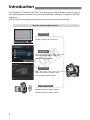
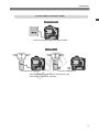
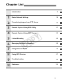

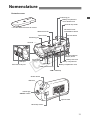
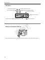
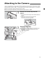
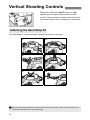
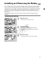

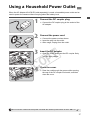
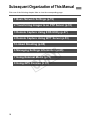
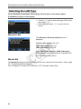
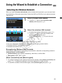

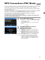
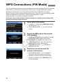
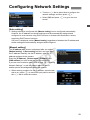
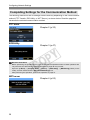


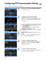
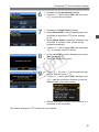
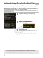
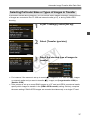
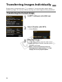
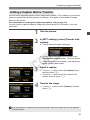
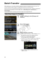
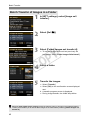
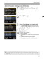
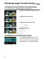
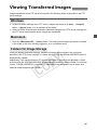


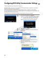
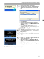
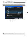

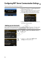
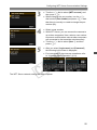
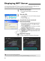
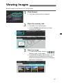
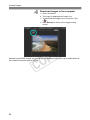
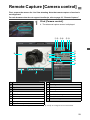
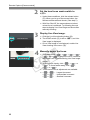
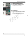
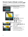
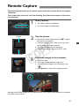


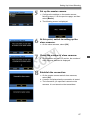
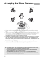
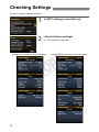
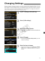
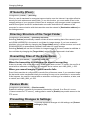
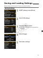
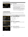

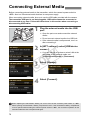
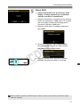
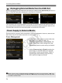
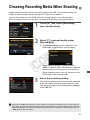
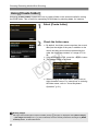
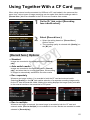
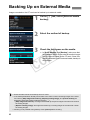
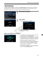
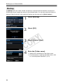
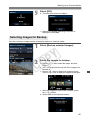
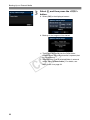
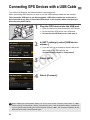
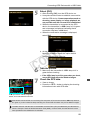

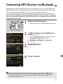
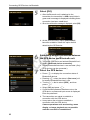
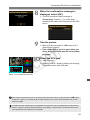


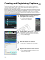
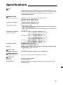


![3 Sélectionnez [Réglages].](http://vs1.manualzilla.com/store/data/006502646_1-716314e518c265d6faa81347dd31fca9-150x150.png)