1
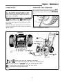
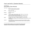
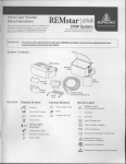
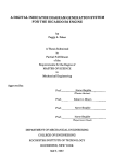
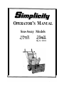
OPERATOR’S M ANUAL
Sno-Away Models
5-55cd22
Mfg. No. 1691411
7-55cd22
Mfg. No. 1691413
Mfg. No. 1691414
BakerTM
OPERATOR’S M ANUAL
Model 7/22E
I
500 N. Spring Street, P.O. Box 997
Port Washinnton, WI 53074-0997
Table Of Contents
SAFETY RULES
General ...........................................................
Preparation.. ..................................................
Operation.. .....................................................
Maintenance & Storage.. ..............................
Safety Decals ................................................
CONTROLS
Snowthrower Controls .................................
Engine Controls.. ...........................................
Engine Speed.. ..............................................
Ground Speed Selector.. ..............................
Deflector.. ......................................................
Scraper Bar & Skid Shoes ...........................
OPERATION
General ..........................................................
Operation on Slopes ....................................
Checks Before Each Start-Up.. ....................
Starting The Engine.. ....................................
Operating The Snowthrower .......................
After Each Use ..............................................
REGULAR MAINTENANCE
Normal Care Chart ......................................... 8
Off-Season Storage ....................................... 8
Starting After Storage .................................. .8
Checking Auger Gear Case.. ....................... .8
.9
Lubrication ....................................................
Checking T i r e Pressure ............................... .9
SERVICE
Troubleshooting ......................................... .lO
Shift Control Adjustment ........................... . l l
Drive Belts ...................................................
.ll
Roller Chain Replacement.. ....................... .13
Shear Pin Replacement.. ............................ .13
Wheel Axle Bearing Replacement.. ............ 14
Auger Shaft Bearing Replacement ........... .14
SPECIFICATIONS.. ............................................ .15
COMMON REPLACEMENT PARTS ................. .16
ACCESSORIES .................................................
.16
TECHNICAL MANUAL AVAILABILITY.. ........... .16
2
.2
.2
.3
.3
.4
4
.4
.4
.5
.5
.6
.6
.6
.6
.6
.7
This manual covers the following models:
I
Model
Mfg. No.
5-55cm
1691411
7-55cm
II
7/22E
I
MODEL REFERENCE
Model Number:
1691413
1691414
I
Manufacturer Number:
1692615
I
I
Engine I.D. Number:
Record your model number, manufacturer number and
serial number in the space provided for easy reference.
The snowthrower I.D. tag is located on the rear of the
frame.
Dealer Name/Date Purchased:
Refer to the Engine Owner’s Manual for location of
engine serial number.
A WARNING
You must read, understand and comply with all safety and operating instructions in this manual before
attempting to set-up and operate your snowthrower.
Failure to comply with all safety and operating instructions can result in loss of machine control, serious
personal injury to you and /or bystanders, and risk equipment and property damage. The triangle in the
text signifies important cautions or warnings which must be followed.
I
A WARNING
Engine exhaust from this product contains chemicals known, in certain quantities, to cause cancer, birth
defects, or other reproductive harm.
1
Safety Rules
* Disengage all clutches (release drive levers) before
starting engine.
WARNING
This unit is a “two-stage” snowthrower. The first
stage is the auger, which feeds the snow back into
the impeller housing. The second stage is the
impeller, which throws the snow out the discharge
chute. If bodily contact is made with the auger or
impeller when they are rotating, severe personal
injury will occur. To avoid injury, keep others and
yourself away from the auger and the discharge
chute whenever the engine is running. Read and
follow all of the safety rules and warnings in this
manual.
l
l
b. Never remove the fuel tank cap or add gasoline to
a running or hot engine.
c. Never fill the fuel tank indoors.
d. Wipe up spilled gasoline.
WARNING
ly.
OPERATION
l
1. Release both drive levers.
2. Shut off the engine.
l
3. Wait for moving parts to stop.
4. Use a narrow board to remove foreign objects
and clear the spout or auger. Never put your
hands into the auger or discharge spout.
l
GENERAL
Never allow children to operate the machine. Do not
allow adults to operate it without proper instruction.
l
. Keep the area of operation clear of all persons, particularly small children and pets.
Never discharge material toward any person or pet.
l
Make sure:
l
b. all safety devices and shields are in place and
working;
1.
c. all adjustments are correct.
l
Use extreme caution when operating on or crossing
gravel drives, walks or roads. Stay alert for hidden
hazards and traffic.
If unit starts to vibrate abnormally, disengage drives
and stop the engine. Check immediately for the
cause. Vibration is generally a warning of trouble.
Before leaving operator’s position for any reason:
- wait for all moving parts to stop.
Before cleaning, repairing or inspecting the unit,
make certain all moving parts have stopped. Remove
the key and then disconnect the spark plug wire to
prevent accidental starting.
. Always use a grounded, 3-wire plug receptacle for
electric starting.
PREPARATION
l
Always clear snow up and down the face of slopes,
never across the face. Use extreme caution when
changing direction on slopes. Do not attempt to clear
slopes over 17.7% (100).
- shut off engine,
- remove the key and
a. snowthrower is in good operating condition;
l
Keep hands and feet away from rotating parts. Keep
clear of discharge opening at all times.
. Be especially careful not to touch snowthrower parts
which might be hot from operation. Allow such parts
to cool before attempting to maintain, adjust or service.
. Read the Operator’s Manual carefully. Be thoroughly
familiar with all controls and proper equipment use.
l
Adjust skid shoe height to clear gravel or crushed
rock surface.
. Do not run engine indoors. Exhaust fumes are dead-
To avoid serious injury, do not put your hands into
the auger housing or discharge spout. If auger
stalls or spout becomes plugged, use the following
procedure to remove objects or clear the spout:
l
Handle gasoline with care - it is highly flammable.
a. Use approved gasoline container.
l
A
Do not operate snowthrower without wearing proper
winter clothing. Wear footwear which improves footing on slippery surfaces.
Never attempt to make any adjustment while engine
is running.
. Adjust snow discharge angle for safe flow when operating near glass enclosures, automobiles, window
wells, dropoffs, etc.
Thoroughly inspect the area where the snowthrower
is to be used and remove all objects such as door
mats, sleds, boards, wires and sticks.
* Do not overload machine capacity by clearing snow
at too fast a ground speed.
2
Safety Rules
l
l
l
l
Never operate machine at high transport speeds on
slippery surfaces. Use care when backing up.
l
Disengage auger drive when transporting or not in
use.
l
Never operate the snowthrower without good vrstbrlrty
or light. Always be sure of your footing.
Safety warning decals are placed at strategic locations
on the snowthrower as a constant reminder to the operator of the most important safety precautions. All warning,
caution and instructional messages on your snowthrower
should be carefully read and obeyed.
* Keep all nuts, bolts and screws tight to ensure that
the equipment is in safe operating condition.
Never store equipment with gasoline in the tank in a
building where fumes may reach an open flame or
spark. Allow the engine to cool before storing in any
enclosure.
!
Run auger drive a few seconds after completion of
throwing snow to help clear out snow and prevent
freeze-up.
SAFETYDECALS
Do not change the engine governor settings or overspeed the engine.
MAINTENANCE & STORAGE
l
Always refer to the Operator’s Manual for important
details if snowthrower is to be stored for an extended
period.
If any of these decals are lost or damaged, replace them
at once. They can be purchased from your local dealer.
A DANGER
A DANGE,R
q -zjzJEJ
Avoid injury from
rotating blower:
Shut 011 engine
before unclogging
discharge chute.
-
Part No. 1677485
Part No. 1677488
Decal supplied by the engine manufacturer.
See your local Tecumseh dealer.
3
Controls
SNOWTHROWER CONTROLS
(Figure 1)
Ref
Name
A
Auger Control
Clutch Lever
B
Drive Control
Clutch Lever
C
Chute Control
Rod
Chute
Deflector
D
E
Function
Engages auger/impeller when
depressed; disengages when
released.
Engages drive to wheels when
depressed; disengages when
released.
Controls direction snow is
thrown.
Controls angle snow is
thrown.
Controls height of scraper
bar.
Skid Shoes
i
Figure 1. Snowthrower Controls
ENGINE CONTROLS
(Figure 2)
Ref Name
1 A 1 Primer
Button
B 1 Choke
Function
1 Primes the carburetor.
Enriches fuel sutmlv.
_
C Ignition
Switch
,D Throttle
Lever
Allows starting and stopping
of the engine.
Controls engine speed.
E Shift Lever
Controls ground speed and
direction.
F
Used to start engine.
Starter
Handle
G Fuel Valve
I
Turns fuel SUDDEN on or off.
I
The engine can be started with the rewind (rope) starter
or optional 12OV electric starter. The engine can be
stopped by moving the throttle lever (D,figure 2) all the
way down, or by pulling out on the ignition key.
Figure 2. Engine Controls
GROUND SPEED
Refer to the engine Owner’s Manual for maintenance
and service instructions, along with important safety
information.
Use the ground speed shift lever (E, figure 2) to control
the drive speed of the snowthrower. There are three forward speeds and one reverse speed. Position 1 is for
extra deep, wet, heavy snow. Positon 2 is for deep, wet,
heavy snow. Position 3 is for light, fluffy snow and to
drive the snowthrower without blowing snow. To change
speeds, first release the drive control clutch lever (B, figure I), then move the ground speed shift lever to the
desired speed setting.
ENGINE SPEED
For overall best performance, run the snowthrower at full
operating engine speed. Use the engine throttle lever (D,
figure 2) to set the engine speed.
4
DEFLECTOR
The angle and distance of the discharged snow is controlled by the position of the deflector. Engine speed also
affects distance of discharge.
The more the deflector is tilted back, the farther snow will
be thrown. Loosen the knob (figure 3) to tilt the deflector
back or forward, then retighten the knob.
SCRAPER BAR & SKID SHOES
On smooth surfaces such as concrete or asphalt, the
scraper bar should scrape the surface. On surfaces such
as gravel, the scraper bar should be high enough so that
it will not pick up gravel or debris.
The height of the scraper bar is controlled by raising or
lowering the skid shoes as shown in figure 4.
1. To raise the scraper bar height, rest the scraper bar
on a piece of wood, equal in thickness to the desired
height.’
Figure 3. Deflector Adjustment
2. Make sure the scraper bar is parallel to the ground
surface.
3. Loosen the skid shoe nuts and let the skid shoes
drop to the surface.
4. Tighten the nuts, making sure the skid shoes are
adjusted equally and are parallel to the surface.
5. To lower the height of the scraper bar, raise the skid
shoes.
6. If the scraper bar becomes worn, it can be replaced
by removing the hardware attaching it to the
snowthrower, installing a new one and then tightening the hardware.
Skidshoe
Figure 4. Skid Shoe Adjustment
Operation
WARNING
I Gasoline is highly Aflammable
and must be handled
GENERAL
A
with care. Never fill the tank when the engine is hot
or runnmg. Always move outdoors to fill the tank.
Keep snowthrower and gasoline away from open
WARNING
1. flame .; spark.
Before leaving the operator’s area for any reason,
stop the engine and remove the key. Disconnect
the spark plug wire and secure it away from the
plug to prevent accidental start-up of the
snowthrower.
A
4 . Position the deflector at the desired angle and the
scraper bar at the desired height.
5. Check the auger control clutch lever (A, figure l),
drive control clutch lever (B, figure 1) and discharge
chute deflector (D, figure 1) for proper operation. If
adjustment is required, sea the Service Section for
procedures.
WARNING
To avoid serious injury, do not put your hands into
the auger housing or discharge spout. If auger
stalls or spout becomes plugged, use the following
procedure to remove objects or clear the spout:
6 . Check the discharge chute control rod (C, figure 1)
for proper function. Check to make sure sprocket
teeth on lower chute control rod fully engage holes in
flange around bottom of discharge chute. The bracket
that holds lower chute control rod is slotted and can
be moved up or down to obtain full engagement of
sprocket teeth.
1. Release both drive levers.
2. Shut off the engine.
3 . Wait for moving parts to stop.
4 . Use a narrow board to remove foreign objects
and clear the spout or auger. Never put your
hands into the auger or discharge spout.
7 . Check shift lever (E, figure 5) for proper position. If
adjustment is required, see SHIFT CONTROL
ADJUSTMENT in the Service Section.
8. Check to make sure spark plug wire is attached and
spark plug is tightened securely into engine. If necessary, torque spark plug to 15 ft. Ibs.
OPERATION ON SLOPES
A
WARNING
9. After servicing engine and before beginning snow
removal, check controls again with engine running.
For your safety, operation on slopes should be in
an up and down direction only. If it becomes necessary to move across the face of a slope, use caution and do not blow snow. Be very careful when
changing direction on a slope.
STARTING THE ENGINE
1. Move the ground speed shift lever (E, figure 5) to the
Neutral position.
Proper winter footwear is recommended for the
operator to help prevent slipping.
2. Turn the fuel valve (G, figure 5) to the ON position.
Never attempt to clean snow from excessively
steep slopes. The maximum slope for any operation is 17.7% (10’).
3. Insert the ignition key (C, figure 5) into the ignition
switch and push fully in to the RUN position.
4. Move the throttle lever (D, figure 5) fully up to the
FAST position.
CHECKS BEFORE EACH START-UP
4. Turn the choke knob (B, figure 5) fully counterclockwise if engine is cold. Do not choke a warm engine.
1. Make sure all safety guards are in place. and all nuts,
bolts and clips are secure.
5. Push the primer button (A, figure 5) two times if
engine is cold. Do not prime a warm engine.
2. Check the engine oil level. See your engine Owner’s
Manual for procedure and specifications.
6. Pull starter handle (F, figure 5) rapidly or push starter
button if equipped with the electric start. Do not allow
starter handle to snap back. Let the starter rope
rewind slowly while keeping a firm hold of the starter
handle.
3. Check the fuel supply. Fill the tank to within l/4 to i/2
inch of top of tank to provide space for expansion.
See your engine Owner’s Manual for fuel recommendations.
6
Operation
7. As the engine warms up and begins to operate evenly, turn the choke knob slowly counterclockwise to the
OFF position. If engine falters, return to l/2 choke
position until it runs smoothly, then turn it to the
choke OFF position.
NOTE: Allow the engine to warm up for a few minutes
before operating the snowthrower. Engine will not develop full power until it reaches operating temperature.
8. Run the engine at or near top speed during
snowthrower operation.
OPERATING THE SNOWTHROWER
1. Position the discharge chute to the desired angle and
direction.
2. Set the ground speed control lever to the desired forward or reverse position.
3. Press the auger clutch lever on the right-hand grip to
begin auger rotation.
Figure 5. Engine Controls
A. Primer Button
D. Throttle Lever
B. Choke Knob
E. Shift Lever
C. Ignition Key/Switch
F. Starter Handle
G. Fuel Valve
4. Press the drive clutch lever on the left-hand grip to
begin moving the snowthrower.
5. To disengage the drive mechanism, release both
clutch levers. Set the ground speed control lever to
the NEUTRAL position.
4. Clean snow and ice from the snowthrower.
5 . If the snowthrower is kept in a cold shelter, fill the fuel
tank to prevent condensation. Do not store near
sparks or flame.
NOTE: After a normal break-in period of 2 - 4 hours of
use, it may be necessary to adjust the drive belt. See
DRIVE BELTS in the Service Section for the adjustment
procedure,
A
WARNING
Never store snowthrower, with gasoline in engine
or fuel tank, in a heated shelter or in enclosed,
poorly ventilated enclosures. Gasoline fumes may
reach an open flame, spark or pilot light (such as a
furnace, water heater, clothes dryer, etc.) and
cause an explosion.
AFTER EACH USE
1. Before stopping engine, pull the starter rope twice
and allow it to rewind slowly, then stop the engine by
moving the throttle lever (D, figure 5) all the way
down or by pulling out on the ignition key. This will
prevent freeze-up.
Handle gasoline carefully. It is highly flammable
and careless use could result in serious fire damage to your person or property.
2. The engine Owner’s Manual contains further information on preventing engine freeze-up.
Drain fuel into an approved container outdoors
away from open flame or sparks.
3. Always remove the key to prevent unauthorized use.
7
Regular Maintenance
NORMAL CARE
I
Check auger gear case lubrication.*
Lubricate
snowthrower.
1 Check tire pressure.
Every 25
H o u r s
See Paae
Care Reauired
I
Page 8
.
Paae9
.
Paae
I
I
9
I
I Check discharge control.
l
.
Change engine oil.**+
Clean or replace spark plug.+
I
Page
14
I
1
I
.
I
1
-a
I
*
i
I
* The transmission and auger gear case have been factory lubricated for life. If lubricant should leak
out, have transmission or auger gear case inspected by your dealer.
**Change original oil after two hours of operation.
9 See your engine Owner’s Manual.
6. Check the operation of the controls. If necessary,
lubricate the snowthrower to improve operation of the
spout control.
OFF-SEASON STORAGE
Before you store your snowthrower for the off-season,
read the Maintenance and Storage instructions in the
Safety Rules section and take the following precautions:
7. Store snowthrower in the wheels down, operating
postion. If stored in any other position, oil from
crankcase could enter cylinder head, causing a service problem. Store in a protected area and cover for
additional protection.
NOTE: Gasoline, if permitted to stand unused for extended periods (30 days or more), may develop gummy
deposits which can adversely affect the engine carburetor and cause engine malfunction. To avoid this condition, add a gasoline stabilizer to the fuel tank or drain all
fuel from the system before placing unit in storage.
CHECK AUGER GEAR CASE
LUBRICATION
1. Prepare your snowthrower engine for storage according to the instructions found in the engine Owner’s
Manual.
1. Place the snowthrower on a level surface.
2. Remove the pipe plug (A, figure 6). The lubricant
should be level with the hole. If not, add Simplicity
Winter Weight Worm Gear Oil (available from your
dealer).
2. Lubricate the snowthrower as described in the
LUBRICATION section.
3.. Clean the snowthrower thoroughly. Coat all exposed
bare metal parts with a good quality paint (available
from you dealer) or a light film of grease, oil or automotive wax.
3. Re-install pipe plug.
STARTING AFTER STORAGE
1. Remove the spark plug and wipe dry. Crank engine a
few times to blow excess oil out of plug hole. Then
I_
reinstall plug.
2. Fill fuel tank with fresh gasoline (unless a duel stabilizer was used).
3. Check to be sure engine fins are clean and air flow is
unobstructed.
4. Check engine oil and lubricate snowthrower.
5. Start the engine outdoors. Do not run engine at high
speeds immediately after starting.
Figure 6. Checking Auger Gear Case Lubrication
8
Regular- Maintenance
LUBRICATION
CHECKING TIRE PRESSURE
A
The air pressure in each tire should be 20 psi (136 kPa)
and should be equal for both tires for best petiormance.
Be sure to keep caps on valves to prevent entry of moisture.
CAUTION
It is very important that grease fittings on auger
shaft (figure 6) are lubricated regularly. If auger
rusts to shaft, damage to worm gear may occur if
shear pins do not break.
With an oil can, apply medium weight (IOW) oil to points
A & i3 shown in figure 7. There are two grease fittings in
the auger shaft (figure 6). Wipe fittings clean and apply
two or three shots of grease. Also, use grease on other
points shown.
Generally, all moving metal parts should be oiled where
contact is made with other parts. Keep oil and grease off
belts and pulleys.
I
Figure 8. Checking Tire Pressure
Transmission
8. Engine
C. Discharge chute
E. Grease fittings
-\
,t
3
Plug
D. Wheeis & axles
Auger gear case
Auger shaft
t A. Use 1OW oil every 10 hours of use and at beginning of each season.
N- 8. Add 5W-30 oil as required. Check engine every 5 hours of use and before each use.
w C. Remove chute and coat unders$te
of flange with clinging type grease annually.
w D. Remove wheels and coat axles with clinging type grease annually.
N E. Add grease to two grease fittings annually.
igure 7. Lubrication Points
9
A WARNING
Before performing any adjustment or service to
snowthrower, stop the engine and wait for moving
parts to stop. Remove the key. To prevent accidental starting, disconnect the spark plug wire and
fasten away from the plug.
4. Broken belt. Replace belt.
5. Shear pin broken. Replace pin.
Auger rotates, but snow not thrown far enough.
1. Spout deflector too low. Adjust deflector as necessary.
2. Engine speed too slow. Set to full throttle.
This section provides troubleshooting and service
instructions. For problems not covered here, contact your
dealer.
3. Ground speed too fast. Use slower speed.
4. Snowthrower discharge spout clogged. STOP engine
and REMOVE the key. DISCONNECT the spark plug
wire. Clear auger using a narrow board. See warning
in SAFETY RULES.
TROUBLESHOOTING
Locate the problem and check the possible cause/remedy in the order listed. Also, refer to the engine manufacturer’s Owner’s Manual for other information. If problem
cannot be remedied, see your dealer.
Engine fails to start.
Scraper bar does not clean hard surface.
1. Skid shoes improperly adjusted. Adjust.
Snowthrower picks up and throws stones on gravel
drive.
1. Key off. Push key in to the ON position.
1. Skid shoes improperly adjusted. Adjust.
2. Fuel valve closed. Turn valve to open position.
Poor traction.
3. Out of fuel. Fill fuel tank.
1. Tires slipping. Check tire pressure and tread.
4. Choke not on. Turn choke fully clockwise to ON position and set throttle up to FAST position.
Auger does not stop when auger lever is released.
5. Engine flooded. Move choke to counterclockwise to
OFF position and try starting engine again.
1 .Auger drive belt out of adjustment. Adjust auger belt.
Snowthrower does not stop when drive lever is
released.
6. Spark plug faulty, fouled or poorly gapped. Clean and
gap or replace.
7. Water in fuel. Drain tank and refill with fresh fuel.
1. Unit drive belt out of adjustment. Adjust drive belt.
Snowthrower does not drive when drive lever is
engaged.
8. Old stale gas. Drain tank and refill with fresh fuel.
Engine starts hard or runs poorly.
1. Drive belts loose, broken or stretched. Adjust or
replace.
1. Fuel mixture too rich. Move choke to OFF position.
2. Drive roller chain damaged. Replace chain.
2. Carburetor adjusted incorrectly. See your dealer.
Discharge control is difficult to operate.
3. Spark plug faulty, fouled or poorly gapped. Clean and
gap or replace.
1. Gears need lubrication. Oil as required.
Cannot shift into all speeds.
4. Fuel cap vent blocked. Clear vent.
1. See SHIFT CONTROL ADJUSTMENT.
Auger does not rotate.
Snowthrower veers to one side.
1. Auger control clutch lever not engaged. Engage
auger control lever.
1. Tire pressure not equal; should be 20 psi
(136 kPa) each side.
2 . Foreign matter blocking auger. STOP.engine and
REMOVE the key. DISCONNECT the spark plug
wire. Clear auger using a narrow board. See warning
in SAFETY RULES.
Excessive vibration.
1. Loose parts or damaged auger. STOP engine and
REMOVE the key. DISCONNECT the spark plug
wire. Tighten all hardware. Replace auger if necessary. If vibration continues, see your dealer.
3 . Auger drive belt slipping. Check auger drive belt
aojusrmenr.
10
SHIFT CONTROL ADJUSTMENT
If any of the following conditions exist, it will be necessary to adjust the shift control.
l
Snowthrower is not in neutral when shift lever is in
NEUTRAL position.
l
Reverse position cannot be fully reached.
l
3rd gear cannot be fully reached.
Adjust as follows:
1. Locate neutral position of shift lever by moving unit
back and forth with traction lever engaged. Unit will
move easily when in neutral.
2. Leave shift lever in position where neutral was
obtained.
3. Loosen screws in shift control bracket (figure 9) at
rear of snowthrower.
4. Slide shift control bracket left or right until shift lever
is properly aligned in neutral position. Tighten screws
in control bracket.
Shift control b
for step 6
5. Check adjustment by moving lever to each position.
Be sure to check to see that NEUTRAL is properly
reached from both forward and reverse directions.
Figure 9. Shift Control Adjustment
6. Check shift lever movement from reverse to 3rd and
make sure lever does not contact handles. To adjust,
loosen two screws indicated in figure 9, move lever
slightly, then tighten the screws and check again.
DRIVE BELTS
The snowthrower is equipped with two drive belts located
just in front of the engine under the belt cover (figure 10).
Figure 11 shows both belts and idler pulleys. The belt
nearest the engine is the unit drive (wheels) belt. The
belt farthest from the engine is the auger/impeller drive
belt.
Do not go near the discharge chute or auger when
the engine is running. Do not run the engine with
11
Adjusting Drive Belts
If the auger or wheels slip under load, belts could be
stretched or worn. Adjust as follows:
Englne
PUIIOY
01
dr;ve bel;
1. Remove the belt cover (figure 10). Determine which
belt requires adjustment.
\
2. Loosen the locknut on the appropriate idler pulley
and move the idler pulley i/4” toward the belt (figure
11). Tighten the locknut.
3. Re-install the belt cover.
4. Determine if additional adjustment is required by trying the unit. Repeat step 1 - 3 if necessary.
NOTE: If auger or wheels continue to slip after adjusting the idler pulleys, the spring (figure 12) on either control rod might be stretched and worn and require replacement. Replace either the auger control rod spring or
drive control rod spring as necessary, then repeat steps
I-4.
Adjusting Belt Guides
‘gure 11. Drive Belts and Pulleys - Belt Cover Off
Check each belt guide for proper clearance using the following procedure.
NOTE: Belt guides on 7 HP mode/s are slight//y different
than shown, but adjustment is the same.
I. Remove the belt cover (figure IO).
2. Have someone hold both the auger and drive clutch
levers tight against the handgrips (figure 12).
3. Loosen the screw securing the belt guide (figure 11).
Adjust the guide so it clears the belt by l/16” - l/8”.
The clearance should be equal on both side of the
pulley. Tighten the screw securely.
NOTE: When adjusting the right belt guide, make sure
guide does not contact the pulley hub.
4. Re-install the belt cover.
Replacing Drive Belts
The drive belts on this snowthrower are of special construction and should be replaced with original equipment
belts available from your dealer. See COMMON
REPLACEMENT PARTS at the back of tfiis.manual for
part numbers.
Use the following procedure to replace either drive belt.
Figure 12. Drive Control Spring
1. Remove gas from fuel tank and run engine until it
stops running from lack of fuel.
4. Loosen the screw securing the belt guide (figure 11).
Pivot the belt guide as necessary and remove the
drive belt from the pulley.
2. Disconnect spark plug wire and fasten it away from
the spark plug.
5. Stand the snowthrower up onto the auger end.
3. Remove belt cover (figure 10).
12
A
CAUTION
Place a block (approximately 4” high) under front
edge of auger housing or snowthrower will not
stand on end.
6. See figure 13. Loosen nuts holding lower belt guard
and slide guard away from belt.
7. Remove belt from between large pulleys.
13. Slide new belt onto pulley and position lower belt
guard to within l/16” - i/8” of large drive pulley.
Tighten nuts securing lower belt guard.
9. Return snowthrower to upright operating position.
10. Place new belt onto engine pulley.
11. Adjust guides as described under ADJUSTING BELT
GUIDES.
12. Install belt cover.
Figure 13. Lower Belt Guard
13. Connect spark plug wire and fill fuel tank.
Keeper link
(Must install towards wheel side
with open end trailing.)
ROLLER CHAIN REPLACEMENT
1. Remove gas from fuel tank and run engine until it
stops running from lack of fuel.
I
2. Disconnect spark plug wire and fasten it away from
the spark plug.
Master link
R
3. Stand the snowthrower up onto the auger end.
I
w
Direction of travel
Figure 14. Roller Chain Master Link
4. Rotate the wheel (figure 13) to locate the roller chain
master link (figure 14).
5. Remove the keeper link, master link and chain.
6. Install new chain and keeper link as shown in figure
14.
7. Return snowthrower to upright operating position.
8. Connect spark plug wire and fill fuel tank.
SHEAR PIN REPLACEMENT,
If the auger strikes an object which could cause damage
to the unit, the shear pin will break. This protects the
gear box and other parts from damage. The shear pins
are shown in figure 15. To replace, install a new shear
pin and cotter pin. Spread the legs of the new cotter pin
fully. Do not replace shear pins with bolts, screws or a
harder shear pin.
Figure 15. Shear Pin Replacement
13
WHEEL AXLE BEARING
REPLACEMENT
After approximately 100 hours of use (about 5 years), or
if drive chain jumps off sprockets, wheel axle bearings
may need to be replaced.
1. Disconnect spark plug wire and fasten it away from
the spark plug.
2. Place a block under the snowthrower so the wheels
are just off the ground.
3. See figure 16. Remove the ring pin and wheel from
each axle.
4. Slide off the washers and long spacer.
A
CAUTION
Bearing
Note the number and placement of washers used
between wheel and long spacer, or between long
spacer and bearing. An even number of washers
must be used on each side of the shaft.
. ,
E-ring
Figure 16. Wheel and Auger Bearings
AUGER SHAFT BEARING
REPLACEMENT
L
5. Pull bearing out of housing opening and off of the
shaft.
If auger shaft bearings need replacement, proceed as
follows:
6. Install new bearing by aligning bearing flat sides with
flat sides in housing.
1. Pry off the E-ring (figure 16).
7. Install washers and long spacer.
2. Remove the washers, then pull the bearing out of the
housing and off the shaft.
8. Install wheel and ring pin.
3. Install new bearing by aligning bearing flat sides with
flat sides in housing.
4. Install washers. Install a new E-ring securely in shaft
groove.
14
I
Specifications
ENGINE
M a k e ................................................................ Tecumseh
Cylinders.. ..................................................................... .1
Cycles............................................................................. 4
Crankshaft ....................................................... Horizontal
5HP
- Model No. ..................................... S e e e n g i n e I.D. plate
-Bore&Stroke.. ........................ Z-13/16 in. x l-15/16 in.
(71.44 mm x 49.23 mm)
- Displacement.. .......................................... .12.04 cu. in.
(197.34 cc)
7HP
- Model No. ..................................... See engine I.D. plate
- Bore & Stroke ............................ 2-314 in. x 2-17132 in.
(69.86 mm x 64.31 mm)
- Displacement.. .......................................... .15.04 cu. in.
(246.5 cc)
Ignition ............................................................... Magneto
Governor.. ...................................................... Mechanical
AUGER HOUSING
Construction.. ............................
Welded steel stampings
Effective Width ..................................... 22 in. (55.88 cm)
Auger Opening Height
with Extension.. ..................................... .16.5 in. (42 cm)
Spout Rotation ........................................................ 1920
Scraper Bar.. .................................... Wear resistant steel
Skid Shoes.. ...................... Adjustable, heat-treated steel
AUGER
Construction.. ........................... Ribbon flite welded steel
Bearings.. ..... Ultr a high Molecular Weight Polyethylene
IMPELLER
Construction.. ............................................ 4 steel blades
Bearings.. ............ Pre-lubricated and sealed ball bearing
Diameter.. ............................................... .lO in. (25.4 cm)
Choke ................................................................... Manual
Lubrication.. ............................................. Splash system
OVERALL DIMENSIONS & WEIGHT
Oil Capacity ...................................... S e e e n g i n e manual
Length ...........................
Fuel Capacity.. .................................. S e e e n g i n e manual
W i d t h ..................................................... 2 4 in. (60.96 cm)
DRIVE
Type __.___________._.______________ Gear drive transmission w/chain
and speed selection
~..........................
51 in. (132 cm)
Height ................................................. 43-l/2 in. (110 cm)
Weight
- 5 - 5 5 ....................................................... , 1 5 8 Ibs. (72 kg)
- 7-55 ........................................................ 178 Ibs. (80 kg)
Speeds.. .......................... Three forward and one reverse
Axle.. ......................................................................... Solid
SPECIFICATIONS ARE CORRECT AT TIME OF PRINTING
AND ARE SUBJECT TO CHANGE WITHOUT NOTICE.
Tire Inflation ......................................... .20 psi (136 kPa)
15
Replacement Parts %I Accessories
COMMON REPLACEMENT PARTS
Listed below are part numbers for the more common
replacement parts. Use only genuine Simplicity replacement parts to assure optimum performance and safety.
Special Worm Gear Oil for Auger Gear Case
- 8 oz. Container.. .............................................. .1704636
- C a s e of 8 oz. containers.. ................................
.I685406
Simplicity Brand SAE 5W30 Cold
Weather Engine Oil
- Case of 1 2 Qts.. ............................................... .1685576
Shear Pin, Auger ............................................... .1668344
Cotter Pin (for shear pin) ................................... .I918447
Equipment Cleaner/Degreaser/Degrimer
- 3 2 oz. Spray Bottle . . . . . . . . . . . . . . . . . . . . . . . . . . . . . . . . . . . . . . . . . . . 1685619
- 1 gallon bottle . . . . . . . . . . . . . . . . . . . . . . . . . . . . . . . . . . . . . . . . . . . . . . . . . . . 1685621
Cleaner/Polish/Protectant
- 8 oz. bottle . . . . . . . . . . . . . . . . . . . . . . . . . . . . . . . . . . . . . . . . . . . . . . . . . . . . . . . . 1685697
Pneumatic Tire Seal - Stops & Prevents Leaks
- 11 oz. tube . . . . . . . . . . . . . . . . . . . . . . . . . . . . . . . . . . . . . . . . . . . . . . . . . . . . . . . . 1685523
- C a s e of 1 2 ( 1 1 oz. tubes) . . . . . . . . . . . . . . . . . . . . . . . . . . . . . . . . . 1685537
- C a s e of 2 4 ( 1 1 oz. tubes) . . . . . . . . . . . . . . . . . . . . . . . . . . . . . . . . . 1685525
ACCESSORIES
See your dealer to purchase any of the following accessories for your snowthrower.
Skid Shoes (set of 2) .......................................... 1685501
Light Kit
Auger Drive Belt.. ............................................... .I674312
Light for late afternoon and early evening snowthrowing.
Wheel Drive Belt - 5 HP ...................................... 1 6 7 4 3 0 8
Electric Start Kit (120V AC)
Wheel Drive Belt - 7 HP.. ................................... .I678600
Grease Gun Kit ................................................... 1 6 8 5 5 1 0
Offers operator the convenience of electric starting.
Available for all models. Standard on some models.
8 oz. Grease Tube.. ............................................. .103077
Touch-Up Paint
- Deep Orange Spray Paint (13 oz. can) ........... .1685611
1685612
- Deep Orange Paint (1 qt. can) ..........................
- Deep Orange Paint (i/2 oz. dauber) ............... .1685615
- Gloss Black Spray Paint (13 oz. can). ............. .1685639
- White Spray Paint (13 oz. can) ____________.______________ 103049
Drift Cutters
Part No.1685189. Helps break through drifts.
Tire
Chains
Increase traction on snowy surfaces (use with caution to
avoid marking surfaces). Available for all models. Not for
use with Snow Hog tires.
USE ONLY GENUINE
SIMPLICIN REPLACEMENT PARTS
Available through your local
authorized SIMPLICITY dealer.
TECHNICAL MANUAL AVAILABILITY
Parts and Repair Manuals are fully illustrated. All of the assemblies are shown in exploded views which show the
relationship of the parts and how they go together. Important assembly notes and special torque values are included
in the illustrations. Standard hardware and torque specification charts are also included.
For the manuals applicable for your model, contact the Simplicity Customer Publications Department at
414-284-8519. Have the following information available when phoning in your request.
Model:
Mfg. No.:
Your Name:
Address:
City, State, Zip:
Vise/Mastercard No.:
Card Expiration Date:
16