1
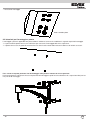
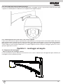
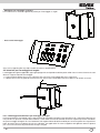
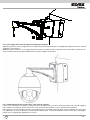
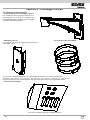
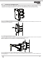
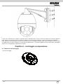
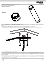
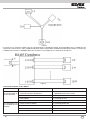
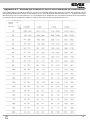
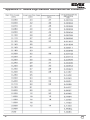
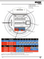
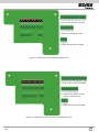
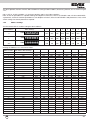
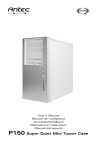
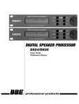
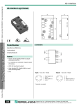
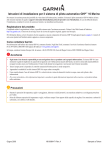
Manuale per l’installazione - Installation manual
Art. 52D0/EIR
Telecamera speed dome IR
IR Speed Dome
Istruzioni per la sicurezza
Le istruzioni che seguono intendono assicurare che l'utente utilizzi il prodotto correttamente al fine di evitare pericolo o perdita
di proprietà. Le misure precauzionali sono suddivise in "Pericolo" e "Attenzione":
Pericolo: L'inosservanza delle istruzioni di pericolo può essere causa di lesioni gravi o morte.
Attenzione: L'inosservanza delle istruzioni di attenzione può essere causa di lesioni o danno all'apparecchiatura.
Pericolo Attenersi alle
seguenti istruzioni per la
sicurezza al fine di evitare
lesioni gravi o morte.
Attenzione Seguire queste precauzioni al fine di
evitare la possibilità di lesioni o danno ai materiali.
Avvertenze
1. Durante l'uso del prodotto attenersi rigorosamente alle normative per la sicurezza elettrica vigenti nel proprio Paese o area
geografica.
2. Utilizzare l'alimentatore, normalmente disponibile in commercio. Lo standard dell'alimentatore è 24V c.a./3A.
3. Non collegare più dispositivi a un solo alimentatore, in quanto un sovraccarico dell'alimentatore potrebbe causare surriscaldamento e il rischio di incendio.
4. Assicurarsi che la spina sia saldamente inserita nella presa di alimentazione.
5. Se il prodotto viene installato su una parete o a soffitto, dovrà essere fissato saldamente.
6. Se dall'apparecchio fuoriescono fumo, odori o rumore, spegnere immediatamente l'apparecchio e scollegare la spina del cavo
di alimentazione, quindi contattare il centro di assistenza.
7. Se il prodotto non funziona correttamente, rivolgersi al proprio rivenditore o al centro di assistenza più vicino. Non cercare
mai di smontare la telecamera. Il produttore non si assume alcuna responsabilità per problemi causati da riparazioni o manutenzione non autorizzate.
Avvertenze
1. Non lasciar cadere la telecamera dome, non sottoporla a urti, non esporla a forti radiazioni elettromagnetiche. Evitare di installare l'apparecchiatura su superfici soggette a vibrazioni o in luoghi soggetti a urti (l'inosservanza di queste raccomandazioni può causare danni all'apparecchiatura).
2. Non collocare la telecamera dome in luoghi eccessivamente caldi, freddi (la temperatura di utilizzo deve essere compresa
tra -30°C ~ +65°C), polverosi o umidi, per evitare il rischio di incendi o scosse elettriche.
3. Il coperchio della telecamera dome per uso interno deve essere protetto dalla pioggia e dall'umidità.
4. Non esporre l'apparecchiatura alla luce diretta del sole, in aree scarsamente aerate o a fonti di calore quali un termosifone
o un radiatore (l'inosservanza di queste raccomandazione può essere causa di incendio).
5. Non rivolgere la telecamera verso la luce solare diretta o luoghi eccessivamente luminosi. In caso contrario si potrebbero
vedere chiazze di luce o strisce verticali luminose (che non indicano tuttavia un malfunzionamento) e influenzare negativamente la resistenza del CCD.
6. Utilizzare il guanto in dotazione quando si apre il coperchio della telecamera dome, evitare il contatto diretto con il coperchio della telecamera dome in quanto l'acidità del sudore delle dita può deteriorarne il rivestimento superficiale.
7. Utilizzare un panno morbido e asciutto per pulire le superfici interne ed esterne del coperchio della telecamera dome, non
utilizzare detergenti alcalini.
Il prodotto è conforme alla direttiva europea 2004/108/CE, 2006/95/CE e successive.
2
I
AVVERTENZE PER L'INSTALLATORE
- Leggere attentamente le avvertenze contenute nel presente documento in quanto forniscono importanti indicazioni riguardanti la sicurezza di installazione, d'uso e di manutenzione.
- Dopo aver tolto l'imballaggio assicurarsi dell'integrità dell'apparecchio. Gli elementi dell'imballaggio (sacchetti di plastica, polistirolo espanso, ecc.) non devono essere lasciati alla portata dei bambini in quanto potenziali fonti di pericolo. L'esecuzione
dell'impianto deve essere rispondente alle norme CEI vigenti.
- È necessario prevedere a monte dell'alimentazione un appropriato interruttore di tipo bipolare facilmente accessibile con separazione tra i contatti di almeno 3mm.
- Prima di collegare l'apparecchio accertarsi che i dati di targa siano rispondenti a quelli della rete di distribuzione.
- Questo apparecchio dovrà essere destinato solo all'uso per il quale è stato espressamente concepito, e cioè per sistemi di
citofonia. Ogni altro uso è da considerarsi improprio e quindi pericoloso. Il costruttore non può essere considerato responsabile per eventuali danni derivanti da usi impropri, erronei ed irragionevoli.
- Prima di effettuare qualsiasi operazione di pulizia o di manutenzione, disinserire l'apparecchio dalla rete di alimentazione
elettrica, spegnendo l'interruttore dell'impianto.
- In caso di guasto e/o di cattivo funzionamento dell'apparecchio, togliere l'alimentazione mediante l'interruttore e non manometterlo. Per l'eventuale riparazione rivolgersi solamente ad un centro di assistenza tecnica autorizzato dal costruttore. Il
mancato rispetto di quanto sopra può compromettere la sicurezza dell'apparecchio.
- Non ostruire le aperture o fessure di ventilazione o di smaltimento calore e non esporre l’apparecchio a stillicidio o spruzzi
d’acqua.
- L'installatore deve assicurarsi che le informazioni per l'utente siano presenti sugli apparecchi derivati.
- Tutti gli apparecchi costituenti l'impianto devono essere destinati esclusivamente all'uso per cui sono stati concepiti.
- L’interruttore onnipolare deve essere facilmente accessibile.
- ATTENZIONE: per evitare di ferirsi, questo apparecchio deve essere assicurato alla parete secondo le istruzioni di installazione.
- Questo documento dovrà sempre rimanere allegato alla documentazione dell'impianto.
Direttiva 2002/96/CE (WEEE, RAEE).
Il simbolo del cestino barrato riportato sull’apparecchio indica che il prodotto, alla fine della propria vita utile, dovendo
essere trattato separatamente dai rifiuti domestici, deve essere conferito in un centro di raccolta differenziata per apparecchiature elettriche ed elettroniche oppure riconsegnato al rivenditore al momento dell’acquisto di una nuova apparecchiatura equivalente.
L’utente è responsabile del conferimento dell’apparecchio a fine vita alle appropriate strutture di raccolta. L’adeguata raccolta
differenziata per l’avvio successivo dell’apparecchio dismesso al riciclaggio, al trattamento e allo smaltimento ambientalmente
compatibile contribuisce ad evitare possibili effetti negativi sull’ambiente e sulla salute e favorisce il riciclo dei materiali di cui è
composto il prodotto. Per informazioni più dettagliate inerenti i sistemi di raccolta disponibili, rivolgersi al servizio locale di smaltimento rifiuti, o al negozio in cui è stato effettuato l’acquisto.
Rischi legati alle sostanze considerate pericolose (WEEE).
Secondo la nuova Direttiva WEEE sostanze che da tempo sono utilizzate comunemente su apparecchi elettrici ed elettronici sono
considerate sostanze pericolose per le persone e l’ambiente. L’adeguata raccolta differenziata per l’avvio successivo dell’apparecchio dismesso al riciclaggio, al trattamento e allo smaltimento ambientalmente compatibile contribuisce ad evitare possibili effetti negativi sull’ambiente e sulla salute e favorisce il riciclo dei materiali di cui è composto il prodotto.
Preparativi per l’installazione
1. Requisiti di base
1) Tutte le operazioni sui dispositivi elettronici devono essere svolte da personale specializzato e in stretta osservanza delle normative locali di sicurezza elettrica, dei regolamenti di prevenzione incendi e di altri regolamenti relativi al luogo di installazione.
2) Controllare la disponibilità di tutti i componenti in base all'elenco contenuto nella confezione e accertarsi che la telecamera
dome e gli accessori siano conformi al luogo di installazione e alla modalità di montaggio richiesta. In caso contrario, contattare il fornitore.
3) Utilizzare questo prodotto in conformità alle condizioni di funzionamento e alle condizioni ambientali richieste.
2. Controllo dello spazio di installazione.
Accertarsi che il luogo destinato all'installazione disponga di spazio sufficiente per il montaggio della telecamera speed
dome e dei relativi accessori.
3. Verifica della resistenza strutturale del punto di installazione.
Accertarsi che la resistenza di soffitti o pareti destinati all'installazione consenta di sopportare almeno 4 volte il peso della
telecamera speed dome e dei relativi accessori.
4. Preparazione dei cavi
- Scegliere il tipo di cavi video in base alla lunghezza di trasmissione. Il cavo video deve soddisfare i seguenti requisiti minimi:
1. Impedenza di 75 Ω
2. Cavo conduttore con anima completamente in rame al 100%.
3. Schermatura intrecciata in rame rivestito al 95%
- Cavi di comunicazione RS485, fare riferimento all'Appendice 2
- Cavo di alimentazione da 24 Vca, fare riferimento all'Appendice 3
5. Conservare tutti gli imballi originali
Si consiglia di conservare tutti i materiali di imballo originali, dopo aver disimballato il prodotto e gli accessori, per successivi utilizzi. Nel caso si necessiti di interventi di assistenza, si consiglia di restituire la telecamera speed dome al rivenditore
o alla fabbrica utilizzando l'imballo originale.
Nota: L'utilizzo di un imballo diverso dall'originale potrebbe causare danni alla telecamera speed dome e comportare di conseguenza costi supplementari di assistenza.
I
3
Sommario
Sommario........................................................................................................................................................4
Capitolo 1 Installazione..................................................................................................................................................................5
1.1
Verifica dell'elenco dei componenti...................................................................................................................................5
1.2
Installazione:......................................................................................................................5
1.2.1 Installazione della telecamera IR Speed Dome...........................................................................................................5
1.3
Impostazioni iniziali...................................................................................................................................................11
1.4
Impostazioni del gruppo di microinterruttori DIP (Dip Switch).......................................................................................11
1.4.1 Posizione dei DIP switch.....................................................................................................................................11
1.4.2 Impostazione dell'indirizzo..................................................................................................................................12
1.4.3 Impostazione del baud-rate..................................................................................................................................13
1.4.4 Impostazione del protocollo..................................................................................................................................14
1.4.5 Impostazione comunicazione Simplex/Half-duplex...............................................................................................14
1.4.6 Impostazioni della resistenza di terminazione...........................................................................................................14
1.5
Collegamenti ingressi/uscite di allarme.........................................................................................................................14
Capitolo 2 Dimensioni staffe di supporto................................................................................................................................15
2.1
Staffa di supporto a braccio lungo per montaggio a parete............................................................................................15
2.2
Staffa di supporto a braccio corto per montaggio a parete............................................................................................15
2.3
Adattatore per montaggio ad angolo............................................................................................................................16
2.4
Adattatore per palo.........................................................................................................................................16
2.5
Adattatore per montaggio a sospensione.....................................................................................................................17
Capitolo 3 Tipi di montaggio a parete....................................................................................................................................17
3.1
Componenti di montaggio.........................................................................................................................................17
3.2
Istruzioni per il montaggio a parete............................................................................................................................18
Capitolo 4 Montaggio ad angolo.............................................................................................................................................19
4.1
Componenti di montaggio.............................................................................................................................................19
4.2
Istruzioni per il montaggio ad angolo..............................................................................................................................20
Capitolo 5 Montaggio su palo.............................................................................................................................................................22
5.1
Componenti di montaggio...............................................................................................................................................22
5.2
Istruzioni per il montaggio su palo...................................................................................................................................23
Capitolo 6 Montaggio a sospensione...................................................................................................................................24
6.1
Componenti di montaggio...............................................................................................................................................24
6.2
Istruzioni per il montaggio a sospensione......................................................................................................................25
Appendice 1 Protezione da fulmini e sovratensione...................................................................................................................27
Appendice 2 Collegamento al bus RS485........................................................................................................................................28
Appendice 3 Sezione dei conduttori da 24 Vca e distanza di trasmissione....................................................................................31
Appendice 4 Tabella degli standard della sezione dei conduttori.....................................................................................................32
4
I
Capitolo 1 - installazione
1.1
Verifica dell'elenco dei componenti
Prima dell'installazione, disimballare la telecamera dome e verificarne le perfette condizioni, controllando anche che tutti i componenti e gli accessori siano compresi facendo riferimento all'elenco contenuto nella confezione.
Nota: L'alimentazione della telecamera dome è 24 Vca/3 A.
1.2
Installazione:
1.2.1
Installazione della telecamera IR Speed Dome
Nota: Le seguenti istruzioni di installazione si applicano a entrambi i modelli di telecamera IR Speed Dome e IR Network Speed
Dome.
1. Installare la staffa di supporto della telecamera dome. Fare riferimento alle sezioni dal Capitolo 2 al Capitolo 7 per informazioni sugli specifici metodi di installazione di differenti staffe di supporto.
2. Installare la scatola posteriore della telecamera IR speed dome e quindi far passare i cavi attraverso la staffa di supporto e
la scatola posteriore. Rimuovere l'adesivo di protezione dal modulo telecamera.
Nota: Nel caso di applicazioni in esterno, applicare nastro sigillante intorno alla superficie di collegamento tra la scatola posteriore e la staffa di supporto oltre a inserire la chiusura a prova di umidità per impedire la penetrazione di acqua all'interno
della telecamera dome.
Adesivo di protezione
Figura 1.2.1 Installazione della scatola posteriore della telecamera dome
Figura 1.2.2 Rimozione dell'adesivo di protezione
3. Configurare l'indirizzo, il baud rate e altre impostazioni della telecamera dome tramite i DIP switch SW1 e SW2 ubicati sulla
scheda sul lato inferiore del modulo della telecamera dome, come illustrato nella Figura 1.2.3 (IR Speed Dome) e nella Figura
1.2.4 (IR Network Speed Dome). Fare riferimento alla Sezione 1.4 Impostazione DIP switch per l'impostazione dell'indirizzo,
del baud rate, del protocollo di comunicazione ecc.
I
5
1. DIP switch indirizzo
2. DIP switch protocollo
3. Impostazioni indirizzo e protocollo
1
2
3
Figura 1.2.3 Scheda sul lato inferiore del modulo della telecamera IR speed dome
6
I
1. DIP switch indirizzo
2. DIP switch protocollo
3. Impostazioni indirizzo e protocollo
4. Porta RJ-45
5. Slot per scheda di memoria SD
1
2
5
4
3
Figura 1.2.4 Scheda sul lato inferiore del modulo della telecamera IR Network speed dome
1. Fissare la guarnizione a tenuta stagna e quindi la catenella di sicurezza alla scatola posteriore.
Nota: è necessario applicare la guarnizione a tenuta stagna per impedire la penetrazione di acqua nella telecamera dome.
I
7
Figura 1.2.5 Fissaggio della guarnizione a tenuta stagna
Figura 1.2.6 Fissaggio della catenella di sicurezza
5. Fissare il gancio della telecamera IR speed dome alla scatola posteriore e quindi inserire i cavi nei corrispondenti slot.
Figura 1.2.7 Fissaggio del gancio della telecamera IR speed dome alla scatola posteriore.
8
I
1: Ingressi/Uscite di allarme (7 ingressi / 2 uscite)
2: Uscita video e RS-485 COM
3: Ingresso tensione 24 Vca e GND (messa a
terra)
Figura 1.2.8 Scheda circuitale della scatola posteriore (IR Speed Dome)
1: Ingressi/Uscite di allarme (7 ingressi / 2
uscite)
2: Ingresso/Uscita audio, uscita video
e morsetti RS-485 COM
3: Ingresso tensione 24 Vca e GND (messa a
terra)
Figura 1.2.9 Scheda circuitale della scatola posteriore (IR Network Speed Dome)
I
9
Utilizzare le viti di montaggio per fissare la telecamera dome.
Figura 1.2.10 Utilizzo delle viti di montaggio per fissare la telecamera dome.
10
I
1.3
Impostazioni iniziali
Codice indirizzo: 0
Baud rate: 2400
Resistenza di terminazione da 120Ω: OFF
1.4
Impostazioni del gruppo di microinterruttori DIP (Dip Switch)
1.4.1
Posizione dei DIP switch
1. DIP switch indirizzo
2. DIP switch protocollo
3. Impostazioni indirizzo e protocollo
1
2
3
Figura 1.4.1 Scheda sul lato inferiore del modulo telecamera
I
11
La telecamera dome è dotata di due DIP switch SW1 e SW2 per la configurazione dell'indirizzo, del baud rate, del protocollo
ecc. della telecamera. Come illustrato nella Figura 1.4.1, ON (Attivato) = 1, OFF (Disattivato) = 0. Nei microinterruttori SW1 e SW2,
1 corrisponde alla posizione inferiore e 8 a quella superiore.
Nota: Essendo la telecamera IR speed dome in grado di adattarsi automaticamente ai protocolli PELCO-D, PELCO-P, PRIVATE-Code, VICON e KALATEL-32 ed essendo la telecamera IR network speed dome in grado di adattarsi automaticamente
ai protocolli Pelco-P, Pelco-D e PRIVATE-Code, non sono necessarie impostazioni dei DIP switch per il protocollo di controllo.
1.4.2
Impostazione dell'indirizzo
Il DIP switch SW1 è utilizzato per impostare l'indirizzo della telecamera dome:
Indirizzo telecamera dome
0
1
255
Impostazioni SW1
S W1
S W1
S W1
1
2
3
4
5
6
7
8
ON
1
2
3
4
5
6
7
8
OFF
OFF
OFF
OFF
OFF
OFF
OFF
OFF
2
3
4
5
6
7
8
ON
OFF
OFF
OFF
OFF
OFF
OFF
OFF
2
3
4
5
6
7
8
ON
ON
ON
ON
ON
ON
ON
ON
ON
1
ON
1
Le impostazioni per gli indirizzi 0~71 sono elencate qui sotto:
Posizione SW1 Impostazioni DIP switch SW1
Indirizzo
1
0
OFF
1
ON
2
OFF
3
ON
4
OFF
5
ON
6
OFF
7
ON
8
OFF
9
ON
10
OFF
11
ON
12
OFF
13
ON
14
OFF
15
ON
16
OFF
17
ON
18
OFF
19
ON
20
OFF
21
ON
22
OFF
23
ON
24
OFF
25
ON
26
OFF
27
ON
28
OFF
29
ON
12
2
OFF
OFF
ON
ON
OFF
OFF
ON
ON
OFF
OFF
ON
ON
OFF
OFF
ON
ON
OFF
OFF
ON
ON
OFF
OFF
ON
ON
OFF
OFF
ON
ON
OFF
OFF
3
OFF
OFF
OFF
OFF
ON
ON
ON
ON
OFF
OFF
OFF
OFF
ON
ON
ON
ON
OFF
OFF
OFF
OFF
ON
ON
ON
ON
OFF
OFF
OFF
OFF
ON
ON
4
OFF
OFF
OFF
OFF
OFF
OFF
OFF
OFF
ON
ON
ON
ON
ON
ON
ON
ON
OFF
OFF
OFF
OFF
OFF
OFF
OFF
OFF
ON
ON
ON
ON
ON
ON
5
OFF
OFF
OFF
OFF
OFF
OFF
OFF
OFF
OFF
OFF
OFF
OFF
OFF
OFF
OFF
OFF
ON
ON
ON
ON
ON
ON
ON
ON
ON
ON
ON
ON
ON
ON
6
OFF
OFF
OFF
OFF
OFF
OFF
OFF
OFF
OFF
OFF
OFF
OFF
OFF
OFF
OFF
OFF
OFF
OFF
OFF
OFF
OFF
OFF
OFF
OFF
OFF
OFF
OFF
OFF
OFF
OFF
7
OFF
OFF
OFF
OFF
OFF
OFF
OFF
OFF
OFF
OFF
OFF
OFF
OFF
OFF
OFF
OFF
OFF
OFF
OFF
OFF
OFF
OFF
OFF
OFF
OFF
OFF
OFF
OFF
OFF
OFF
8
OFF
OFF
OFF
OFF
OFF
OFF
OFF
OFF
OFF
OFF
OFF
OFF
OFF
OFF
OFF
OFF
OFF
OFF
OFF
OFF
OFF
OFF
OFF
OFF
OFF
OFF
OFF
OFF
OFF
OFF
I
31
32
33
34
35
36
37
38
39
40
41
42
43
44
45
46
47
48
49
50
51
52
53
54
55
56
57
58
59
60
61
62
63
64
65
66
67
68
69
70
71
ON
OFF
ON
OFF
ON
OFF
ON
OFF
ON
OFF
ON
OFF
ON
OFF
ON
OFF
ON
OFF
ON
OFF
ON
OFF
ON
OFF
ON
OFF
ON
OFF
ON
OFF
ON
OFF
ON
OFF
ON
OFF
ON
OFF
ON
OFF
ON
ON
OFF
OFF
ON
ON
OFF
OFF
ON
ON
OFF
OFF
ON
ON
OFF
OFF
ON
ON
OFF
OFF
ON
ON
OFF
OFF
ON
ON
OFF
OFF
ON
ON
OFF
OFF
ON
ON
OFF
OFF
ON
ON
OFF
OFF
ON
ON
ON
OFF
OFF
OFF
OFF
ON
ON
ON
ON
OFF
OFF
OFF
OFF
ON
ON
ON
ON
OFF
OFF
OFF
OFF
ON
ON
ON
ON
OFF
OFF
OFF
OFF
ON
ON
ON
ON
OFF
OFF
OFF
OFF
ON
ON
ON
ON
ON
OFF
OFF
OFF
OFF
OFF
OFF
OFF
OFF
ON
ON
ON
ON
ON
ON
ON
ON
OFF
OFF
OFF
OFF
OFF
OFF
OFF
OFF
ON
ON
ON
ON
ON
ON
ON
ON
OFF
OFF
OFF
OFF
OFF
OFF
OFF
OFF
ON
OFF
OFF
OFF
OFF
OFF
OFF
OFF
OFF
OFF
OFF
OFF
OFF
OFF
OFF
OFF
OFF
ON
ON
ON
ON
ON
ON
ON
ON
ON
ON
ON
ON
ON
ON
ON
ON
OFF
OFF
OFF
OFF
OFF
OFF
OFF
OFF
OFF
ON
ON
ON
ON
ON
ON
ON
ON
ON
ON
ON
ON
ON
ON
ON
ON
ON
ON
ON
ON
ON
ON
ON
ON
ON
ON
ON
ON
ON
ON
ON
ON
OFF
OFF
OFF
OFF
OFF
OFF
OFF
OFF
OFF
OFF
OFF
OFF
OFF
OFF
OFF
OFF
OFF
OFF
OFF
OFF
OFF
OFF
OFF
OFF
OFF
OFF
OFF
OFF
OFF
OFF
OFF
OFF
OFF
OFF
OFF
OFF
OFF
OFF
OFF
OFF
OFF
ON
ON
ON
ON
ON
ON
ON
ON
OFF
OFF
OFF
OFF
OFF
OFF
OFF
OFF
OFF
OFF
OFF
OFF
OFF
OFF
OFF
OFF
OFF
OFF
OFF
OFF
OFF
OFF
OFF
OFF
OFF
OFF
OFF
OFF
OFF
OFF
OFF
OFF
OFF
OFF
OFF
OFF
OFF
OFF
OFF
OFF
OFF
1.4.3
Impostazione del baud-rate
I microinterruttori nelle posizioni 1-3 del DIP Switch SW2 vengono utilizzati per impostare il baud rate della telecamera dome.
Le impostazioni 100~101 corrispondono rispettivamente al baud rate di 2400 bps, 4800 bps e 9600 bps. Per valori di baud rate
al di fuori del precedente intervallo, il valore predefinito è 2400 bps. Fare riferimento alla seguente tabella:
DIP switch SW2 - Impostazioni baud rate
Baud Rate
2400
Impostazione posizioni 1-3
SW2
SW2
4800
9600
I
SW2
1
2
3
ON
1
2
3
4
5
6
7
8
ON
OFF
OFF
2
3
4
5
6
7
8
OFF
ON
OFF
2
3
4
5
6
7
8
ON
ON
OFF
ON
1
ON
1
13
1.4.4
Impostazione del protocollo
I microinterruttori nelle posizioni 4-6 del DIP switch SW2 vengono utilizzati per impostare i protocolli della telecamera dome. Fare
riferimento alla seguente tabella (il modello di telecamera speed dome di rete non supporta il protocollo relativo alla codifica Manchester):
DIP switch SW2 - Impostazioni protocollo
Protocollo
4
5
6
OFF
ON
ON
ON
ON
ON
Impostazioni posizioni 4-6
SW2
Bosch Manchester
SW2
AD Manchester
Auto-adattativo
ON
1
2
3
4
5
6
7
8
2
3
4
5
6
7
8
ON
1
Altri
1.4.5
Impostazione comunicazione Simplex/Half-duplex
Il microinterruttore nella posizione 7 del DIP switch SW2 viene utilizzato per impostare il metodo di comunicazione della telecamera dome come simplex o half-duplex.
DIP switch SW2 - Impostazioni Simplex/Half-duplex
Descrizione
Impostazione posizione 7
SW2
Simplex
SW2
Half-duplex
7
ON
1
2
3
4
5
6
7
8
OFF
2
3
4
5
6
7
8
ON
ON
1
1.4.6
Impostazioni della resistenza di terminazione
Il microinterruttore nella posizione 8 del DIP Switch SW2 viene utilizzato per impostare il resistore di terminazione da 120 Ω
della telecamera dome.
Descrizione
DIP Switch SW2-Terminating Resistor Settings
Impostazione posizione 8
SW2
Not Terminated
SW2
Terminated
1.5
8
ON
1
2
3
4
5
6
7
8
OFF
2
3
4
5
6
7
8
ON
ON
1
Collegamenti ingressi/uscite di allarme
D
DC
C IR Speed Dome e la telecamera IR Network Speed Dome a 7 ingressi di allarme (0~12 Vcc)
È possibile collegare la telecamera
e 2 uscite di allarme. Fare riferimento al seguente schema:
DC Load
Dome
Relay Output
OUT( n)
+
DC -
OUT( n)
GND OUT
DC
Dome
OUT( n)
12VDC
30mA
JQC- 3FG
Relay
( 10 A 250VAC)
ᨺ220V AC
L
N
Relay OutputDC
OUT( n)
Diagram (left)
Diagram(right)
L'allarme fornisce l'uscita relè (senza tensione) e quando viene collegata al dispositivo di allarme è richiesta un'alimentazione
esterna. Per l'alimentazione in c.c. (schema a sinistra), la tensione di ingresso deve rientrare nella gamma 12 Vcc, 30 mA. Per
l'alimentazione in c.a., è necessario utilizzare il relè esterno (schema a destra) per prevenire danni all'unità ed evitare il rischio
di scosse elettriche.
14
I
Capitolo 2 - dimensioni staffe di supporto
2.1 Staffa di supporto a braccio lungo per montaggio a parete
2.2 Staffa di supporto a braccio corto per montaggio a parete
I
15
2.3 Adattatore per montaggio ad angolo
2.4 Adattatore per palo
16
I
2.5 Adattatore per montaggio a sospensione
Capitolo 3 - tipi di montaggio a parete
3.1 Componenti di montaggio
Staffa di supporto per montaggio a parete
Per telecamere dome sospese montate a parete in interno/esterno
I
17
-- Accessori di montaggio
Dadi e rondelle piatte
3.2 Istruzioni per il montaggio a parete
Il montaggio a parete è applicabile alle pareti solide in ambiente /esterno che soddisfano i seguenti requisiti di montaggio:
- Lo spessore della parete deve essere sufficiente per consentire il montaggio delle viti a espansione.
- La parete deve essere in grado di sostenere fino a 8 volte il carico totale della telecamera dome e dei relativi accessori.
Fase 1: Con un trapano praticare i fori di montaggio sulla parete e montare le viti a espansione
Praticare quattro fori sulla parete in base alle posizioni di montaggio e quindi inserire altrettante viti a espansione M6 (non fornite) nei fori di montaggio.
18
I
Fase 2: Fissaggio della staffa di supporto alla parete
Fissare le viti a espansione attraverso la staffa di supporto per il montaggio a parete e la guarnizione utilizzando quattro dadi
esagonali con rondelle piatte in modo da fissare il supporto di montaggio alla parete.
Fase 3: Montaggio della telecamera dome sulla staffa di supporto
Far passare i cavi attraverso l'apertura superiore della scatola posteriore, avvitare quest'ultima nelle filettature della staffa di supporto e quindi utilizzare viti M3 per fissare la telecamera dome. Fare riferimento alla Sezione 1.2 per le istruzioni di installazione.
Nota: Seguire la stessa procedura descritta sopra per il montaggio della staffa di supporto a braccio corto. Per applicazioni in
esterno, adottare misure di impermeabilizzazione. La staffa di supporto a braccio corto per il montaggio a parete non è consigliata per applicazioni in esterno.
Capitolo 4 - montaggio ad angolo
4.1 Componenti di montaggio
- Staffa di supporto per montaggio a parete.
Per telecamere dome sospese utilizzate in interno/esterno con l'uso di un adattatore per montaggio ad angolo, adattatore per
montaggio a parete o adattatore per palo.
I
19
- Adattatore per montaggio ad angolo
Per l'utilizzo con la staffa di supporto da parete per il montaggio su angoli.
- Accessori di montaggio
Viti a testa esagonale (M8×30), dadi, rondelle elastiche e rondelle piatte
4.2 Istruzioni per il montaggio ad angolo
Il montaggio ad angolo è applicabile agli angoli sporgenti in corrispondenza di due pareti solide a 90° in interno/esterno che soddisfano i seguenti requisiti di montaggio:
- Lo spessore della parete deve essere sufficiente per consentire il montaggio delle viti a espansione.
- La parete deve essere in grado di sostenere fino a 8 volte il carico totale della telecamera dome e dei relativi accessori.
Fase 1: Montaggio dell'adattatore per montaggio ad angolo
Praticare quattro fori nell'angolo in base alle posizioni di montaggio e quindi inserire altrettante viti a espansione M6 (non fornite) nei fori. Far passare il cavo di alimentazione, il cavo video e la linea di controllo attraverso l'apertura presente nell'adattatore per montaggio ad angolo. Fissare l'adattatore sull'angolo utilizzando dadi e rondelle per serrare le quattro viti a espansione.
Nota: Accertarsi che la lunghezza dei cavi sia sufficiente. Per applicazioni in esterno, applicare del sigillante attorno l'apertura
per i cavi al fine di evitare la penetrazione di acqua e liquidi.
20
I
Fase 2: Fissaggio della staffa di supporto all'adattatore angolare
Applicare quattro viti a testa esagonale con le rondelle elastiche all'adattatore per il montaggio ad angolo attraverso la staffa di
supporto e la guarnizione.
Nota: Quando si serrano le viti, è meglio comprimere prima la rondella elastica e quindi ruotarla mezzo giro in modo da mantenere l'effetto richiesto di impermeabilizzazione senza danneggiare le filettature.
Fase 3: Montaggio della telecamera dome sulla staffa di supporto
Far passare i cavi attraverso l'apertura superiore della scatole posteriore e fissare la telecamera dome alla staffa di supporto.
Infine utilizzare le viti M3 per fissare le due unità. Fare riferimento alla Sezione 1.2 per le istruzioni di installazione.
Nota: Seguire la stessa procedura descritta in precedenza per il montaggio ad angolo della staffa di supporto a braccio corto.
Per applicazioni in esterno, adottare misure di impermeabilizzazione. La staffa di supporto a braccio corto per il montaggio a
parete non è consigliata per applicazioni in esterno.
I
21
Capitolo 5 - montaggio su palo
5.1 Componenti di montaggio
- Staffa di supporto per montaggio a parete
Per telecamere dome sospese utilizzate in interno/esterno con l'uso di un adattatore per
montaggio ad angolo, adattatore per montaggio
a parete o adattatore per palo.
- Adattatore per palo
Per l'utilizzo con staffa di supporto da parete per il
montaggio su pali.
- Fascette di acciaio inossidabile
Per l'uso con l'adattatore per palo, con la possibilità di selezionare le seguenti dimensioni:
59-82 mm, 84-108 mm, 103-127 mm, 130-152 mm, 155-178 mm, 180-203 mm, 194-216 mm;
Su richiesta possono essere fornite dimensioni personalizzate in base alle esigenze dell'utente.
- Accessori di montaggio
Viti a testa esagonale (M8×30) e rondelle elastiche
22
I
5.2
Istruzioni per il montaggio su palo
Il montaggio su palo è applicabile ai pilastri solidi in ambiente interno/esterno che soddisfano i seguenti requisiti di montaggio:
- Il diametro del palo deve essere compatibile con le dimensioni di montaggio delle fascette di acciaio inossidabile.
- Il palo deve essere in grado di sostenere fino a 8 volte il carico totale della telecamera dome e dei relativi accessori.
Fase 1: Assemblaggio dell'adattatore per il montaggio su palo
Utilizzare un cacciavite per allentare le tre fascette di acciaio inossidabile e quindi inserirle facendole passare attraverso i fori
rettangolari presenti sull'adattatore.
Fase 2: Montaggio dell'adattatore per palo
Far passare la linea di controllo, il cavo video e il cavo di alimentazione attraverso l'apertura centrale e fissare le tre fascette di
acciaio inossidabile al palo, infine utilizzare il cacciavite per fissare le viti alle fascette.
Nota: Per applicazioni in esterno, adottare misure di impermeabilizzazione.
Fase 3: Installazione della staffa di supporto da parete sul gruppo assemblato dell'adattatore
Avvitare quattro viti a testa esagonale con le rondelle elastiche all'adattatore per il palo attraverso la staffa di supporto da parete e la guarnizione.
I
23
Fase 4: Montaggio della telecamera dome sulla staffa di supporto
Far passare i cavi attraverso l'apertura superiore della scatola posteriore, fissare la telecamera dome alla staffa di supporto e
infine utilizzare le viti M3 per fissare la telecamera dome. Fare riferimento alla Sezione 1.2 per le istruzioni di installazione.
Nota: Seguire la stessa procedura descritta in precedenza per il montaggio ad angolo della staffa di supporto a braccio corto.
Per applicazioni in esterno, adottare misure di impermeabilizzazione. La staffa di supporto a braccio corto per il montaggio a
parete non è consigliata per applicazioni in esterno.
Capitolo 6 - montaggio a sospensione
6.1 Componenti di montaggio
- Base di montaggio
24
I
Per telecamere dome sospese con l'uso di un supporto sospensore e relativo adattatore.
- Supporto sospensore
- Adattatore
6.2
Istruzioni per il montaggio a sospensione
Il montaggio di questo tipo è applicabile a soffitti solidi in ambiente interno/esterno che soddisfano i seguenti requisiti di montaggio:
- Lo spessore del soffitto deve essere sufficiente per consentire il montaggio delle viti a espansione.
- Il soffitto deve essere in grado di sostenere fino a 8 volte il carico totale della telecamera dome e dei relativi accessori.
Fase 1: Montaggio della base di montaggio
Con un trapano praticare quattro fori φ6 nel soffitto in base alle posizioni dei fori di fissaggio sulla base e quindi inserire le viti
a espansione M6 (non fornite) nei fori. Far passare il cavo di alimentazione, il cavo video e la linea di controllo attraverso l'apertura presente nella base di montaggio. Fissare la base di montaggio sull'angolo utilizzando dadi e rondelle per serrare le quattro viti a espansione.
Nota: Accertarsi che la lunghezza dei cavi sia sufficiente. Per applicazioni in esterno, adottare misure di impermeabilizzazione
tra la superficie del soffitto e la base di montaggio e attorno all'apertura per i cavi. Il montaggio a sospensione non è consigliato
per ambienti esposti direttamente alla pioggia.
I
25
Fase 2: Montaggio del supporto sospensore
Imperniare l'adattatore nel corrispondente supporto sospensore e quindi usare le viti di fissaggio per fissare i due componenti.
Estrarre i cavi attraverso il supporto sospensore e avvitare tale supporto nella base di montaggio, utilizzando le viti di fissaggio
per fissare i due componenti.
Nota: Per applicazioni in esterno, applicare il composto impermeabile sulle filettature.
Fase 3: Montaggio della telecamera dome sulla staffa di supporto
Far passare i cavi attraverso l'apertura superiore della scatola posteriore e fissare la telecamera al supporto sospensore, infine
utilizzare le viti M3 per fissare la telecamera dome. Fare riferimento alla Sezione 1.2 per le istruzioni di installazione.
Nota: In caso di altezza insufficiente del soffitto, fissare direttamente la telecamera dome alla base di montaggio senza utilizzare il supporto sospensore, come illustrato nella figura qui sopra a destra.
26
I
Appendice 1 - protezione da fulmini e sovratensione
Questo prodotto è dotato di tecnologia di protezione dai fulmini con piastra di massa TVS per evitare i danni causati da segnali
d'impulso al di sotto dei 3000 W, quali fulmini, sovratensioni, ecc. In base alle effettive condizioni esterne occorre tuttavia adottare anche le misure preventive necessarie per garantire la sicurezza elettrica.
1. La distanza tra i cavi di trasmissione del segnale e l'apparecchiatura o i cavi ad alta tensione deve essere di almeno 50 m.
2. I cablaggi esterni vanno collocati il più possibile al riparo sotto le gronde.
3. In aree aperte, i cablaggi devono essere interrati in canaline di acciaio a tenuta stagna; la canalina di acciaio deve disporre
di un punto di messa a terra. Non utilizzare cablaggi sospesi.
4. In aree soggette a forti temporali o ad alte tensioni di induzione (ad esempio una sottostazione di trasformatori di alta tensione) è necessario aggiungere un apparecchio di protezione di fulmini e un conduttore a prova di fulmine.
5. Nella progettazione dell'installazione e dei collegamenti elettrici relativamente alla protezione dai fulmini e alla messa a terra
si deve prendere in considerazione anche la protezione dai fulmini dell'edificio, nonché garantire la conformità agli standard locali applicabili e agli standard industriali.
6. Il sistema deve essere messo a terra in maniera equipotenziale. L'apparecchiatura di messa a terra deve soddisfare i requisiti di sistema anti-interferenze e di sicurezza elettrica, non deve andare in cortocircuito o aprire il circuito con il conduttore di
neutro in presenza di una rete di distribuzione ad alta tensione. Quando il sistema viene messo a terra separatamente, la resistenza deve essere minore o uguale a 4 Ω, e l'area della sezione del cavo di messa a terra non deve essere inferiore a 25 mm2.
Per le istruzioni di messa a terra, consultare il Manuale di installazione della telecamera Speed Dome.
I
27
Appendice 2 - collegamento al Bus RS485
1. Proprietà generali del Bus RS485
Secondo lo standard industriale il Bus RS485 è un Bus di comunicazione semi-duplex con impedenza caratteristica di 120 Ω,
con capacità di carico massimo di 32 dispositivi connessi (incluso il dispositivo di controllo e il dispositivo controllato).
2. Distanza di trasmissione del Bus RS485
Di seguito viene riportata la tabella teorica della distanza massima di trasmissione con cavo doppino ritorto da 0,56 mm (24
AWG), rispetto a diversi valori di baud rate:
Baud Rate
2400BPS
4800BPS
9600BPS
Distanza massima
1800m
1200m
800m
La distanza di trasmissione diminuisce se si utilizza un cavo più sottile, oppure se si utilizza il dispositivo in condizioni di elevata interferenza elettromagnetica, oppure se al bus sono collegati molti dispositivi; in caso contrario, la distanza di trasmissione
aumenta.
3. Metodo di collegamento e resistenza di terminazione
1) Lo standard industriale del bus RS485 richiede un metodo di collegamento "daisy-chain" (a cascata) tra i dispositivi. Entrambi i lati devono essere collegati a una resistenza di terminazione da 120 Ω (illustrata nello Schema 1), il metodo di collegamento semplificato è illustrato nello Schema 2, ma la distanza di “D” non deve essere eccessiva.
Schema 1
Schema 2
2) Collegamento della resistenza di terminazione da 120Ω
La resistenza di terminazione da 120 Ω può essere collegata tramite il DIP switch sulla scheda di comunicazione, come nella
telecamera high speed dome illustrata in Figura 3. Per una nuova telecamera dome, la resistenza di accoppiamento da 120
Ω viene riconosciuta come non collegata; per collegarla attivare l'ottavo bit di SW2. Viceversa, disattivare l'ottavo bit di SW2
per scollegarla.
28
I
1. DIP switch indirizzo
2. DIP switch protocollo
3. Impostazioni indirizzo e protocollo
1
2
3
Figura 3
4. Problemi di applicazione pratica
In genere gli utenti utilizzano la connessione a stella per i collegamenti. In questo caso le resistenze di terminazione devono essere collegate tra i due dispositivi più lontani (come illustrato nella Figura 4, 1# e 15#). Questo metodo di collegamento, tuttavia, non soddisfa i requisiti dello standard industriale del bus RS485, si avranno pertanto problemi di riflessione del segnale e
riduzione della capacità anti-interferenze quando i dispositivi sono lontani. In tal caso la telecamera dome non risponderà ai comandi, si attiverà da sola, ecc.
I
29
Figura 4
In questo caso la soluzione migliore consiste nell'aggiungere un distributore RS485. Questo prodotto riesce a modificare efficacemente la connessione a stella, soddisfacendo in tal modo i requisiti dello standard industriale del bus RS485: si evitano così
i suddetti inconvenienti e l'affidabilità della comunicazione risulta migliorata. Far riferimento alla Figura 5.
Figura 5
1. Domande frequenti sul bus RS485
Fault Phenomenon
Probable Cause
Solutions
The speed dome do 1. The address or Baud Rate is not matched bet- 1. Adjust the address or Baud Rate of Host or
the self chack but an
ween Host and the speed Dome
Speed Dome to make a match
not be controlled
2. RS485+, - are connected incorrectly
2. Change the RS 485+ and RS485- wires
3. Wiring drops
3. Fastening the wire
4. RS485 wire broke:
4. Change RS485 wire
The speed dome can 1. Loose contact of RS485
be controlled but not
2. One RS485 wire broke
smoothly
3. Host and speed dome are too far away
1. Fastening RS485 wire
4. Too many speed domes are connected
4. Add RS485 distributor
30
2. Change RS485 wire
3. Add terminal matched resistance
I
Appendice 3 - sezione dei conduttori da 24 Vca e distanza di trasmissione
Nella tabella seguente è indicata la distanza massima raccomandata utilizzata per determinate sezioni dei conduttori con una
percentuale di perdita di tensione di 24 Vca inferiore al 10%. Per il dispositivo azionato da tensione c.a., la percentuale di perdita di tensione massima consentita è il 10%. Ad esempio, per un dispositivo con una potenza nominale di 80 VA installato a
una distanza di 10 metri dall'alimentatore, la sezione minima richiesta per il conduttore è di 0,8 mm.
D istance
feet(m)
Wire Gauge
mm
Pow er (va)
I
31
Appendice 4 - tabella degli standard della sezione dei conduttori
32
I
Safety Instruction
These instructions are intended to ensure that user can use the product correctly to avoid danger or property loss. The precaution
measure is divided into “Warnings” and “Cautions”:
Warnings: Neglecting any of the warnings may cause serious injury or death.
Cautions: Neglecting any of the cautions may cause injury or equipment damage.
Warnings Follow these Cautions Follow these
safeguards to prevent precautions to prevent
serious injury or death.
potential injury or material
damage.
Warnings
1. In the use of the product, you must be strict compliance with the electrical safety regulations of the nation and region.
2. Please use the power adapter, which is provided by normal company. The standard of the power adapter is AC24V/3A.
3. Do not connect several devices to one power adapter as adapter overload may cause over-heat or fire hazard.
4. Please make sure that the plug is firmly connected on the power socket.
5. When the product is installed on wall or ceiling, the device shall be firmly fixed.
6. If smoke, odors or noise rise from the device, turn off the power at once and unplug the power cable, and then please contact the service center.
7. If the product does not work properly, please contact your dealer or the nearest service center. Never attempt to disassemble the camera yourself. (We shall not assume any responsibility for problems caused by unauthorized repair or maintenance.)
Warnings
1. Do not drop the dome or subject it to physical shock, and do not expose it to high electromagnetism radiation. Avoid the
equipment installation on vibrations surface or places subject to shock (ignorance can cause equipment damage).
2. Do not place the dome in extremely hot, cold (the operating temperature shall be -30°C ~ +65°C), dusty or damp locations,
or fire or electrical shock will occur otherwise.
3. The dome cover for indoor use shall be kept from rain and moisture.
4. Exposing the equipment to direct sun light, low ventilation or heat source such as heater or radiator is forbidden (ignorance
can cause fire danger).
5. Do not aim the camera at the sun or extra bright places. A blooming or smear may occur otherwise (which is not a malfunction however), and affecting the endurance of CCD at the same time.
6. Please use the provided glove when open up the dome cover, avoid direct contact with the dome cover, because the acidic
sweat of the fingers may erode the surface coating of the dome cover.
7. Please use a soft and dry cloth when clean inside and outside surfaces of the dome cover, not to use alkaline detergents.
Product is according to EC Directive 2004/108/EC and following norms.
GB
33
SAFETY INSTRUCTIONS FOR INSTALLERS
- Carefully read the instructions on this leaflet: they give important information on the safety, use and maintenance of the installation.
- After removing the packing, check the integrity of the set. Packing components (plastic bags, expanded polystyrene etc.) are
dangerous for children. Installation must be carried out according to national safety regulations.
- It is convenient to fit close to the supply voltage source a proper bipolar type switch with 3 mm separation (minimum) between contacts.
- Before connecting the set, ensure that the data on the label correspond to those of the mains.
- This apparatus must only be used for the purpose for which it was expressly designed, e.g. for audio or video door entry systems. Any other use may be dangerous. The manufacturer is not responsible for damage caused by improper, erroneous or
irrational use.
- Before cleaning or maintenance, disconnect the set.
- In the event of faults and/or malfunctions, disconnect from the power supply immediately by means of the switch and do not
tamper with the apparatus.
- For repairs apply only to the technical assistance centre authorized by the manufacturer.
- Safety may be compromised if these instructions are disregarded.
- Do not obstruct opening of ventilation or heat exit slots and do not expose the set to dripping or sprinkling of water. No objects filled with liquids, such as vases, should be placed on the apparatus.
- Installers must ensure that manuals with the above instructions are left on connected units after installation, for users' information.
- All items must only be used for the purposes designed.
- WARNING: to prevent injury, this apparatus must be securely attached to the floor/wall in accordance with the installation
instructions.
- This leaflet must always be enclosed with the equipment.
Directive 2002/96/EC (WEEE)
The crossed-out wheelie bin symbol marked on the product indicates that at the end of its useful life, the product must
be handled separately from household refuse and must therefore be assigned to a differentiated collection centre for electrical and electronic equipment or returned to the dealer upon purchase of a new, equivalent item of equipment.
The user is responsible for assigning the equipment, at the end of its life, to the appropriate collection facilities.
Suitable differentiated collection, for the purpose of subsequent recycling of decommissioned equipment and environmentally
compatible treatment and disposal, helps prevent potential negative effects on health and the environment and promotes the
recycling of the materials of which the product is made. For further details regarding the collection systems available, contact
your local waste disposal service or the shop from which the equipment was purchased.
Risks connected to substances considered as dangerous (WEEE).
According to the WEEE Directive, substances since long usually used on electric and electronic appliances are considered
dangerous for people and the environment. The adequate differentiated collection for the subsequent dispatch of the appliance
for the recycling, treatment and dismantling (compatible with the environment) help to avoid possible negative effects on the
environment and health and promote the recycling of material with which the product is compound.
Preparation for Installation
1. Basic requirements
1) All the electronic operation should be strict compliance with the local electrical safety regulations, fire prevention regulations
and other related regulations at the installation place.
2) Check whether all the accessories are there according to the packing list, make sure that the place and installation mode are
conform to the demands, if not, please contact the supplier.
3) Please use this product according to the working environment.
2. Check installation space.
Make sure the place have enough space to install the speed domes and its accessories.
3. Check the intensity of conformation at the installation scene. Please make sure that the endure ability of ceilings or walls is
4 times as the weight of speed dome and its accessories.
4. Preparation of cables
- Choose the video cable according to the transmission length. The video should meet the least demands as:
1. 75Ω resistance
2. 100% copper core conducting wire.
3. 95% weaving copper shield.
- RS485 communication cable, please refer to Appendix 2
- 4V AC power cable, please refer to Appendix 3
5. Please keep all wrappers
Please keep all wrappers after unpack them for future use. In case of any failure occurred, please return the speed dome to
the factory with the original wrapper.
Note: Transportation without the original wrapper may result in damage on the speed dome and cost additional charge.
34
GB
Table of Contents
Table of Contents.....................................................................................................................................................................35
Chapter 1
Installation....................................................................................................................................................................36
1.1
Check Parts List..............................................................................................................................................36
1.2
Installation....................................................................................................................................36
1.2.1
IR Speed Dome Installation.............................................................................................................................36
1.3
Initial Settings ...................................................................................................................................................42
1.4
DIP Switch Settings........................................................................................................................................42
1.4.1
DIP Switch Location....................................................................................................................................42
1.4.2
Address Settings............................................................................................................................................43
1.4.3
Baud Rate Settings.....................................................................................................................................44
1.4.4
Protocol Settings.......................................................................................................................................45
1.4.5
Simplex/Half-duplex Settings......................................................................................................................45
1.4.6
Terminating Resistor Settings..................................................................................................................45
1.5
Alarm In/Out Connections..........................................................................................................................45
Chapter 2 Mounts Dimension..................................................................................................................................................46
2.1
Long-arm Wall Mount..................................................................................................................................46
2.2
Short-arm Wall Mount..................................................................................................................................46
2.3
Corner Adapter............................................................................................................................................47
2.4
Pole Adapter..............................................................................................................................................47
2.5
Pendant Adapter........................................................................................................................................46
Chapter 3 Wall Mounting Applications.......................................................................................................................................48
3.1
Mounting Components................................................................................................................................48
3.2
Wall Mounting Instructions.........................................................................................................................49
Chapter 4 Corner Mounting Applications...................................................................................................................................50
4.1
Mounting Components...........................................................................................................................50
4.2
Corner Mounting Instructions.................................................................................................................51
Chapter 5 Pole Mounting Applications......................................................................................................................................53
5.1
Mounting Components...............................................................................................................................53
5.2
Pole Mounting Instructions......................................................................................................................54
Chapter 6 Pendant Mounting Applications..........................................................................................................................55
6.1
Mounting Components............................................................................................................................55
6.2
Pendant Mounting Instructions..............................................................................................................56
Appendix 1 Lightning & Surge Protection............................................................................................................................58
Appendix 2 RS485 Bus Connection....................................................................................................................................59
Appendix 3 24VAC Wire Gauge & Transmission Distance..................................................................................................62
Appendix 4 Table of Wire Gauge Standards................................................................................................................................63
GB
35
Chapter 1 - installation
1.1
Check Parts List
Prior to installation, unpack the dome unit and check whether it is in good condition and all parts and accessories are included
by referring to the packing list.
Note: The power supply for the dome is 24VAC/3A.
1.2
Installation
1.2.1
IR Speed Dome Installation
Note: The following installation instructions are applicable to both IR Speed Dome and the IR Network Speed Dome models.
1. Install the dome mount. Please refer to the related sections from Chapter2 to Chapter7 for specific installation methods of
different mounts.
2. Install the back box of the IR speed dome, and then feed out the cables through the mount and back box. Remove the protective sticker from the dome drive.
Note: During the outdoor application, please apply the thread seal tape around the connection between the back box and
mount as well as insert with the damp-proof stopper to prevent water from entering the dome.
Protective sticker
Figure 1.2.1 Install the Back Box of Dome
Figure 1.2.2 Remove the Protective Sticker
3. Configure the dome address, baud rate and other settings through DIP switch SW1 and SW2 located on the bottom board
of the dome drive, as shown in Figure 1.2.3 (IR Speed Dome) and Figure 1.2.4 (IR Network Speed Dome). Please refer to Section 1.4 DIP Switch Settings for setting address, baud rate, communication protocol, etc.
36
GB
1. Address DIP Switch
2. Protocol DIP Switch
3. Address and Protocol Settings
1
2
3
Figure 1.2.3 Bottom Board of IR Speed Dome Drive
GB
37
1. Address DIP Switch
2. Protocol DIP Switch
3. Address and Protocol Settings
4. RJ-45 Port
5. SD Card Slot
1
2
5
4
3
Figure 1.2.4 Bottom Board of IR Network Speed Dome Drive
4. Attach the O-ring and then the safety chain to the back box.
Note: The O-ring must be applied to prevent water from entering the dome.
38
GB
Figure 1.2.5 Attach the O-ring
Figure 1.2.6 Attach the Safety Chain
5. Fasten the hook of IR speed dome to the back box and then plug the cables into their matching slots respectively.
Figure 1.2.7 Fasten the Hook of IR Speed Dome to the Back Box
GB
39
1: Alarm In/Out (7 inputs/2outputs)
2: Video Out and RS-485 COM
3: 24VAC Voltage Input and GND
Figure 1.2.8 Back Box Circuit Board (IR Speed Dome)
1: Alarm In/Out (7 inputs/2outputs)
2: Audio In/Out, Video Out and
RS-485 COM Terminals
3: 24VAC Voltage Input and GND
Figure 1.2.9 Back Box Circuit Board (IR Network Speed Dome)
40
GB
5. Use the mounting screws to secure the dome.
Figure 1.2.10 Use the Mounting Screws to Secure the Dome
GB
41
1.3 Initial Settings
Address code: 0
Baud rate: 2400
120Ω terminator: OFF
1.4
DIP Switch Settings
1.4.1
DIP Switch Location
1. Address DIP Switch
2. Protocol DIP Switch
3. Address and Protocol Settings
1
2
3
Figure 1.4.1 Bottom Board of Dome Drive
42
GB
The dome provides two DIP switches SW1 and SW2 for setting the dome address, baud rate, protocol, etc. As shown in Figure
1.4.1,
ON=1, OFF=0. In SW1 and SW2, 1 is the lowest position and 8 is the highest position.
Note: As the IR speed dome is capable of being self-adaptive to PELCO-D, PELCO-P, PRIVATE-Code, VICON and KALATEL32 protocols, and the IR network speed dome is self-adaptive to Pelco-P, Pelco-D and PRIVATE-Code protocols as well, no DIP
switch settings for control protocol are required.
1.4.2
Address Settings
The DIP Switch SW1 is used for setting the dome address:
Dome Address
0
1
255
SW1 Settings
S W1
S W1
S W1
1
2
3
4
5
6
7
8
ON
1
2
3
4
5
6
7
8
OFF
OFF
OFF
OFF
OFF
OFF
OFF
OFF
2
3
4
5
6
7
8
ON
OFF
OFF
OFF
OFF
OFF
OFF
OFF
2
3
4
5
6
7
8
ON
ON
ON
ON
ON
ON
ON
ON
ON
1
ON
1
Settings for address 0~71 are listed as below:
SW1 Position
Address
0
1
2
3
4
5
6
7
8
9
10
11
12
13
14
15
16
17
18
19
20
21
22
23
24
25
26
27
28
29
30
GB
DIP Switch SW1 Settings
1
OFF
ON
OFF
ON
OFF
ON
OFF
ON
OFF
ON
OFF
ON
OFF
ON
OFF
ON
OFF
ON
OFF
ON
OFF
ON
OFF
ON
OFF
ON
OFF
ON
OFF
ON
OFF
2
OFF
OFF
ON
ON
OFF
OFF
ON
ON
OFF
OFF
ON
ON
OFF
OFF
ON
ON
OFF
OFF
ON
ON
OFF
OFF
ON
ON
OFF
OFF
ON
ON
OFF
OFF
ON
3
OFF
OFF
OFF
OFF
ON
ON
ON
ON
OFF
OFF
OFF
OFF
ON
ON
ON
ON
OFF
OFF
OFF
OFF
ON
ON
ON
ON
OFF
OFF
OFF
OFF
ON
ON
ON
4
OFF
OFF
OFF
OFF
OFF
OFF
OFF
OFF
ON
ON
ON
ON
ON
ON
ON
ON
OFF
OFF
OFF
OFF
OFF
OFF
OFF
OFF
ON
ON
ON
ON
ON
ON
ON
5
OFF
OFF
OFF
OFF
OFF
OFF
OFF
OFF
OFF
OFF
OFF
OFF
OFF
OFF
OFF
OFF
ON
ON
ON
ON
ON
ON
ON
ON
ON
ON
ON
ON
ON
ON
ON
6
OFF
OFF
OFF
OFF
OFF
OFF
OFF
OFF
OFF
OFF
OFF
OFF
OFF
OFF
OFF
OFF
OFF
OFF
OFF
OFF
OFF
OFF
OFF
OFF
OFF
OFF
OFF
OFF
OFF
OFF
OFF
7
OFF
OFF
OFF
OFF
OFF
OFF
OFF
OFF
OFF
OFF
OFF
OFF
OFF
OFF
OFF
OFF
OFF
OFF
OFF
OFF
OFF
OFF
OFF
OFF
OFF
OFF
OFF
OFF
OFF
OFF
OFF
8
OFF
OFF
OFF
OFF
OFF
OFF
OFF
OFF
OFF
OFF
OFF
OFF
OFF
OFF
OFF
OFF
OFF
OFF
OFF
OFF
OFF
OFF
OFF
OFF
OFF
OFF
OFF
OFF
OFF
OFF
OFF
43
31
32
33
34
35
36
37
38
39
40
41
42
43
44
45
46
47
48
49
50
51
52
53
54
55
56
57
58
59
60
61
62
63
64
65
66
67
68
69
70
71
ON
OFF
ON
OFF
ON
OFF
ON
OFF
ON
OFF
ON
OFF
ON
OFF
ON
OFF
ON
OFF
ON
OFF
ON
OFF
ON
OFF
ON
OFF
ON
OFF
ON
OFF
ON
OFF
ON
OFF
ON
OFF
ON
OFF
ON
OFF
ON
ON
OFF
OFF
ON
ON
OFF
OFF
ON
ON
OFF
OFF
ON
ON
OFF
OFF
ON
ON
OFF
OFF
ON
ON
OFF
OFF
ON
ON
OFF
OFF
ON
ON
OFF
OFF
ON
ON
OFF
OFF
ON
ON
OFF
OFF
ON
ON
ON
OFF
OFF
OFF
OFF
ON
ON
ON
ON
OFF
OFF
OFF
OFF
ON
ON
ON
ON
OFF
OFF
OFF
OFF
ON
ON
ON
ON
OFF
OFF
OFF
OFF
ON
ON
ON
ON
OFF
OFF
OFF
OFF
ON
ON
ON
ON
ON
OFF
OFF
OFF
OFF
OFF
OFF
OFF
OFF
ON
ON
ON
ON
ON
ON
ON
ON
OFF
OFF
OFF
OFF
OFF
OFF
OFF
OFF
ON
ON
ON
ON
ON
ON
ON
ON
OFF
OFF
OFF
OFF
OFF
OFF
OFF
OFF
ON
OFF
OFF
OFF
OFF
OFF
OFF
OFF
OFF
OFF
OFF
OFF
OFF
OFF
OFF
OFF
OFF
ON
ON
ON
ON
ON
ON
ON
ON
ON
ON
ON
ON
ON
ON
ON
ON
OFF
OFF
OFF
OFF
OFF
OFF
OFF
OFF
OFF
ON
ON
ON
ON
ON
ON
ON
ON
ON
ON
ON
ON
ON
ON
ON
ON
ON
ON
ON
ON
ON
ON
ON
ON
ON
ON
ON
ON
ON
ON
ON
ON
OFF
OFF
OFF
OFF
OFF
OFF
OFF
OFF
OFF
OFF
OFF
OFF
OFF
OFF
OFF
OFF
OFF
OFF
OFF
OFF
OFF
OFF
OFF
OFF
OFF
OFF
OFF
OFF
OFF
OFF
OFF
OFF
OFF
OFF
OFF
OFF
OFF
OFF
OFF
OFF
OFF
ON
ON
ON
ON
ON
ON
ON
ON
OFF
OFF
OFF
OFF
OFF
OFF
OFF
OFF
OFF
OFF
OFF
OFF
OFF
OFF
OFF
OFF
OFF
OFF
OFF
OFF
OFF
OFF
OFF
OFF
OFF
OFF
OFF
OFF
OFF
OFF
OFF
OFF
OFF
OFF
OFF
OFF
OFF
OFF
OFF
OFF
OFF
1.4.3
Baud Rate Settings
The positions 1-3 of DIP Switch SW2 are used for setting the baud rate of dome. The settings 100~101 respectively corresponds to the baud rate of 2400bps, 4800bps and 9600bps. For baud rate out of the above range, the default setting is 2400bps.
Refer to the following table:
DIP Switch SW2-Baud Rate Settings
Baud Rate
2400
Positions1-3 Settings
SW2
SW2
4800
9600
44
SW2
1
2
3
ON
1
2
3
4
5
6
7
8
ON
OFF
OFF
2
3
4
5
6
7
8
OFF
ON
OFF
2
3
4
5
6
7
8
ON
ON
OFF
ON
1
ON
1
GB
1.4.4
Protocol Settings
The positions 4-6 of DIP Switch SW2 are used for setting the communication protocols of dome. Refer to the following table
(network speed dome model does not support Manchester code protocol):
DIP Switch SW2-Protocol Settings
Protocol
4
5
6
OFF
ON
ON
ON
ON
ON
Positions 4-6 Settings
SW2
Bosch Manchester
SW2
AD Manchester
Self-adaptive
ON
1
2
3
4
5
6
7
8
2
3
4
5
6
7
8
ON
1
Others
1.4.5
Simplex/Half-duplex Settings
The position 7 of DIP Switch SW2 is used for setting the communication method of dome to simplex or half-duplex.
DIP Switch SW2-Simplex/Half-duplex Settings
Description
Position 7 Setting
SW2
Simplex
SW2
Half-duplex
7
ON
1
2
3
4
5
6
7
8
OFF
2
3
4
5
6
7
8
ON
ON
1
1.4.6
Terminating Resistor Settings
The position 8 of DIP Switch SW2 is used for setting the 120Ω terminating resistor of dome.
Description
DIP Switch SW2-Terminating Resistor Settings
Position 8 Setting
SW2
Not Terminated
SW2
Terminated
8
ON
1
2
3
4
5
6
7
8
OFF
2
3
4
5
6
7
8
ON
ON
1
1.5
Alarm In/Out Connections
D
DC
C
The IR Speed Dome and IR Network Speed Dome can be connected with 7 alarm inputs (0~12VDC) and 2 alarm outputs. Refer
to the following diagram:
DC Load
Dome
Relay Output
OUT( n)
+
DC -
OUT( n)
DC
Dome
GND OUT
OUT( n)
12VDC
30mA
JQC- 3FG
Relay
( 10 A 250VAC)
ᨺ220V AC
L
N
Relay OutputDC
OUT( n)
Diagram (left)
GB
Diagram(right)
45
Chapter 2 - mounts dimension
2.1 Long-arm Wall Mount
2.2 Short-arm Wall Mount
46
GB
2.3 Corner Adapter
2.4 Pole Adapter
GB
47
2.5 Pendant Adapter
Chapter 3 - wall mounting applications
3.1 Mounting Components
- Wall Mount
Applicable to indoor/outdoor pendant domes.
48
GB
I
- Mounting Accessories
3.2 Wall Mounting Instructions
The wall mounting is applicable to the indoor/outdoor solid wall construction which should comply with the following mounting
requirements:
- The wall must be thick enough to install the expansion screws.
- The wall must be capable of supporting up to 8 times the total load of the dome and its accessories.
Step1: Drill mounting holes in the wall and install the expansion screws
Drill four holes in the wall according to the mounting locations, and then insert M6 expansion screws (not supplied) into the mounting holes.
Step 2: Secure the wall mount to the wall
Fasten the expansion screws through the wall mount and gasket by using four hex nuts with flat washers to secure the wall mount
to the wall.
GB
I
49
Step 3: Install dome to the mount
Feed cables through the opening on top of the back box, screw the back box into the threads in the mount, and then use M3
screws to secure the dome. Refer to Section 1.2 for installation instructions.
Note: Follow the same instructions described above for the Short-arm Wall Mount installation. For outdoor applications, please
adopt the water-proof measures. The Short-arm Wall Mount is not recommended for outdoor applications.
Chapter 4 - corner mounting applications
4.1 Mounting Components
- Wall Mount
Applicable to the indoor/outdoor pendant domes with the use of corner adapter, wall adapter or pole adapter.
50
GB
I
- Corner Adapter
For use with the wall mount in the corner mounting applications.
- Mounting Accessories
4.2 Corner Mounting Instructions
The corner mounting is applicable to the indoor/outdoor 90° solid corner construction which should comply with the following
mounting requirements:
- The wall must be thick enough to install the expansion screws.
- The wall must be capable of supporting up to 8 times the total load of the dome and its accessories.
Step1: Install the corner adapter
Drill four holes in the corner according to the mounting locations, and then insert M6 expansion screws (not supplied) into the
holes. Pull the power cord, video cable and control line through the opening of the corner adapter. Secure the corner adapter
to the corner by using nuts and washers to tighten the four expansion screws.
Note: Make sure the cables have enough length. For outdoor applications, please apply the sealant around the cable opening
to prevent water.
GB
I
51
Step 2: Secure the wall mount to the corner
Apply four hex screws with the spring washers to the corner adapter through the wall mount and gasket.
Note: When tightening the screw, it is better to compress the spring washer firstly and then rotate half a round so as to maintain required waterproof effect without damaging the threads.
Step 3: Install dome to the mount
Feed the cables through the opening on top of the back box, and attach the dome to the mount. Finally, use M3 screws to secure the two units. Refer to Section 1.2 for installation instructions.
Note: Follow the same instructions described above for the Short-arm Corner Mount installation. For outdoor applications,
please adopt the water-proof measures. The Short-arm Wall Mount is not recommended for outdoor applications.
52
GB
Chapter 5 - pole mounting applications
5.1 Mounting Components
- Wall Mount
Applicable to indoor/outdoor pendant domes with the
use of corner adapter, wall adapter or pole adapter.
- Pole Adapter
For use with the wall mount in the pole mounting applications.
- Stainless Steel Straps
For use with the pole adapter, with the following dimensions selectable:
59-82mm, 84-108mm, 103-127mm, 130-152mm, 155-178mm, 180-203mm, 194-216mm;
Customized dimensions can also be provided according to user’s demand.
- Mounting Accessories
Hex Screws (M8×30) and Spring Washers
GB
53
5.2
Pole Mounting Instructions
The pole mounting is applicable to the indoor/outdoor solid pole construction which should comply with the following mounting requirements:
- The diameter of pole must be constituent with the mounting dimensions of the stainless steel straps.
- The pole construction must be capable of supporting up to 8 times the total load of the dome and its accessories.
Step1: Assemble the pole mount adapter
Use a screwdriver to loosen the three stainless steel straps and then insert them through the rectangle holes on the pole adapter.
Step 2: Install pole adapter
Feed the control line, video cable and power cable through the central opening and secure the three stainless steel straps to
the pole, and finally use the screwdriver to fasten the screws at the steel straps.
Note: For outdoor applications, please adopt the water-proof measures.
Step 3: Install wall mount assembly
Screw four hex screws with the spring washers to the pole adapter through the wall mount and gasket.
54
GB
Step 4: Install dome to the mount
Feed the cables through the opening on top of the back box, and attach the dome to the mount, and finally use M3 screws to
secure the dome. Refer to Section 1.2 for installation instructions.
Note: Follow the same instructions described above for the Short-arm Corner Mount installation. For outdoor applications,
please adopt the water-proof measures. The Short-arm Wall Mount is not recommended for outdoor applications.
Chapter 6 - pendant mounting applications
6.1 Mounting Components
- Mounting Base
GB
55
Applicable to pendant domes with the use of the pendant pole and pole adapter.
- Pendant Pole
- Pendant Adapter
6.2
Pendant Mounting Instructions
The pendant mounting is applicable to the indoor/outdoor solid ceiling construction which should comply with the following
mounting requirements:
- The ceiling must be thick enough to mount the expansion screws.
- The ceiling must be capable of supporting up to 8 times the total load of the dome and its accessories.
Step 1: Install the mounting base
Drill four 6 holes in the ceiling according to the fastener holes locations of the mounting base, and then insert M6 expansion
screws (not supplied) into the holes. Pull the power cord, video cable and control line through the opening at the mounting
base. Secure the mounting base to the corner by using nuts and washers to tighten the four expansion screws.
Note: Make sure the cables have enough length. For outdoor applications, please apply water-proof measures between the ceiling surface and mounting base and around the cables opening. The pendant mounting application is not recommended for outdoor environment where directly suffers rain.
56
GB
Step 2: Install the pendant pole
Swivel the pendant adapter into the matching pendant pole and then use the retainer screws to secure the two parts. Pull out
the cables through the pendant pole and screw the pendant pole into the mounting base and use the set screws to secure the
two parts as well.
Note: For outdoor applications, please apply the water-proof thread compound to the threads.
Step 3: Install dome to the mount
Feed the cables through the opening on top of the back box, and attach the dome to the pendant pole, and finally use M3
screws to secure the dome. Refer to Section 1.2 for installation instructions.
Note: In case of insufficient ceiling height, directly attach the dome to the mounting base without use of pendant pole, as shown
in the figure right above.
GB
57
Appendix 1- lightning & surge protection
This product adopts TVS plate lightning protection technology to avoid damage caused by pulse signal that is below 3000W,
like instantaneous lighting, surging, etc. According to the actual situation outdoors, necessary protection measures must be taken
to secure the electrical safety.
1. The distance between signal transmission line and High-voltage equipment or high-voltage cable is at least 50m.
2. Outdoor wiring should better be along the eaves as much as possible.
3. In the open field, wiring should be buried underground in sealed steel pipe, and the steel-pipe should be one-point grounding. Overhead routing method is forbidden.
4. In strong thunderstorm area or high induction voltage areas (such as high-voltage transformer substation), high power lightning protection apparatus and lightning conductor are necessary to be appended.
5. The design for installation and wiring with lightning protection and grounding in mind should be combined with the lightning
protection consideration of the building, and conform to the related national standards and industry standards.
6. The system should be equipotentially grounded, and the grounding equipment must satisfy double-request of system antijamming and electric safety, and it must not appear short circuit and open circuit with the zero conductor of strong grid. When
the system is grounding individual, the resistance should be no more than 4Ω, the section al area of the grounding cable
should be no less than 25mm2. For grounding instructions, please refer to the Installation Manual of Speed Dome.
58
GB
Appendix 2 - RS485 Bus connection
1. General Property of RS485 Bus
According to RS485 industry Bus standard, RS485 is a half-duplex communication bus which has 120Ω characteristic impendence, the maximum load ability is 32 payloads (including controller device and controlled device).
2. RS485 Bus Transmission Distance
When using 0.56mm (24AWG) twisted-pair line, according to different baud rate, the max transmission distance theory table
is shown as below:
Baud Rate
2400BPS
4800BPS
9600BPS
Max Distance
1800m
1200m
800m
The transmission distance will be decreased if we use the thinner cable, or use this product under the strong electromagnetic
interference situation, or there are lots of devices are added to the bus; on the contrary, the transmission distance will be increased.
3. Connection Method and Terminal Resistance
1) RS485 industry bus standard require daisy-chain connection method between any devices, both sides have to connect a
120Ω terminal resistance (show as Diagram 1), the simplified connection method is shown as diagram 2, but the distance
of “D” should not be too long.
Diagram 1
Diagram 2
2) Connection of 120Ω terminal resistor
The 120Ω terminal resistor can be connected through the DIP switch on the communications board, as high speed dome
shown in Figure3. For a new dome, the 120Ω matching resistor is defaulted as unconnected, switch on the eighth bit of
SW2, it will be connected. Conversely, switch off the eighth bit of SW2, it will be unconnected.
GB
59
1. Address DIP Switch
2. Protocol DIP Switch
3. Address and Protocol Settings
1
2
3
Figure 3
4. Problems in the Practical Application
Normally, users adopt star-shape connection method in construction, under this situation, the terminal resistors must be connected between two farthest devices (as Figure 4, 1# and 15#), but this connection method is not satisfy the requirement of the
RS485 industry standard so that it will lead to some problems such as signal reflection, anti-jamming ability decline when the
devices are faraway. At this time, the dome will be uncontrollable, or self-running, etc.
60
GB
Figure 4
For such case, the best way is adding a RS485 distributor. This product can effectively change the star-shape connection to
which satisfies the requirement of RS485 industry standard, in order to avoid those problems and improve the communication
reliability. Show as figure 5.
1. FAQ of RS485 Bus
Fault Phenomenon
Probable Cause
Solutions
The speed dome do 1. The address or Baud Rate is not matched bet- 1. Adjust the address or Baud Rate of Host or
the self chack but an
ween Host and the speed Dome
Speed Dome to make a match
not be controlled
2. RS485+, - are connected incorrectly
2. Change the RS 485+ and RS485- wires
3. Wiring drops
3. Fastening the wire
4. RS485 wire broke:
4. Change RS485 wire
The speed dome can 1. Loose contact of RS485
be controlled but not
2. One RS485 wire broke
smoothly
3. Host and speed dome are too far away
1. Fastening RS485 wire
4. Too many speed domes are connected
4. Add RS485 distributor
GB
2. Change RS485 wire
3. Add terminal matched resistance
61
Appendix 3 - 24VAC wire gauge & transmission distance
The following table has described the recommended max. distance adopted for the certain wire gauge when the 24VAC voltage
loss rate is less than 10%. For the AC driven device, the maximum voltage loss rate allowable is 10%. For example, for a device with the rating power of 80VA which is installed at a distance of 35 feet (10m) away from the transformer, then the minimum
wire gauge required is 0.8000mm.
D istance
feet(m)
Wire Gauge
mm
Pow er (va)
62
GB
Appendix 4 - table of wire gauge standards
GB
63
Via Pontarola, 14/a
35011 Campodarsego PD
Tel. +39 049 920 2511
Fax +39 049 920 2603
www.elvox.com
S6I.52D.IR0 RL. 00 13 01
ELVOX - Campodarsego - Italy