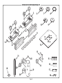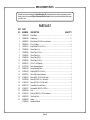
1
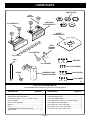
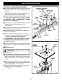
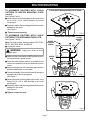
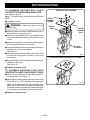
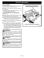
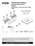
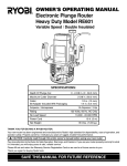
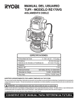
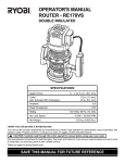
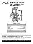
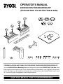
OPERATOR'S MANUAL
#4950300 ROUTER MOUNTING KIT
(FOR USE WITH THE BT3000 TABLE SAW)
CONGRATULATIONS AND THANK YOU FOR BUYING THIS RYOBI ROUTER MOUNTING KIT.
Your new #4950300 Router Mounting Kit has been designed for use with the RYOBI BT3000 Table Saw. It has
been engineered and manufactured to Ryobi’s high standards for dependability, ease of operation, and operator
safety. This kit gives you the capability of mounting a router on the accessory table of your BT3000. Properly cared
for, it will provide years of dependable, trouble-free performance.
SAVE THIS MANUAL FOR FUTURE REFERENCE
RULES FOR SAFE OPERATION
■ READ THESE INSTRUCTIONS THOROUGHLY
before assembling or using this router mounting kit.
■ READ THE INSTRUCTIONS AND RULES OF
SAFE OPERATION FOR THE BT3000 TABLE
SAW before operating your saw with this kit.
■ KEEP ASSEMBLY AREA AND WORK AREA
CLEAN. Cluttered areas and benches invite accidents.
■ ALWAYS WEAR SAFETY GLASSES. Everyday
eyeglasses have only impact-resistant lenses; they
are NOT safety glasses.
■ DO NOT USE THIS PRODUCT WITH OTHER
EQUIPMENT OR FOR OTHER PURPOSES.
■ ALWAYS DISCONNECT SAW FROM POWER
SUPPLY BEFORE ASSEMBLING THIS KIT. Make
sure switch is off when reconnecting saw to power
supply.
■ DO NOT MAKE ADJUSTMENTS until cutter
has come to a complete stop and tool has been
disconnected from power source.
■ FEED WORKPIECE AGAINST ROTATION OF
CUTTER.
■ DO NOT USE AWKWARD HAND POSITIONS.
■ KEEP FINGERS away from revolving cutter, use
fixtures when necessary.
■ WHENEVER POSSIBLE, always use dust cover
for overhead guarding.
■ DO NOT REMOVE JAMMED CUT OFF PIECES
UNTIL cutter has stopped and tool has been
disconnected from power source.
■ HOLD WORKPIECE FIRMLY AGAINST THE
TABLE.
■ UNUSED SAW MAY CAUSE PERSONAL INJURY.
Disconnect motor cord from the receptacle on your
saw and plug accessory power cord into the
receptacle. Always use the saw's master switch to
turn the accessory ON and OFF.
■ NEVER USE A ROUTER BIT larger in diameter
than the opening in the router mounting plate.
■ SAVE THESE INSTRUCTIONS. Refer to them
frequently and use to instruct other users. If you
loan someone this accessory, loan them these
instructions also.
The purpose of safety symbols is to attract your attention to possible dangers. The safety symbols, and the
explanations with them, deserve your careful attention and understanding. The safety warnings do not by
themselves eliminate any danger. The instructions or warnings they give are not substitutes for proper
accident prevention measures.
SYMBOL
MEANING
SAFETY ALERT SYMBOL: Indicates danger, warning, or caution. May be used in conjunction
with other symbols or pictographs.
DANGER: Failure to obey a safety warning will result in serious injury to yourself or to others.
Always follow the safety precautions to reduce the risk of fire, electric shock, and personal
injury.
WARNING: Failure to obey a safety warning can result in serious injury to yourself or to others.
Always follow the safety precautions to reduce the risk of fire, electric shock, and personal injury.
CAUTION: Failure to obey a safety warning may result in property damage or personal injury.
Always follow the safety precautions to reduce the risk of fire, electric shock and personal injury.
NOTE: Advises you of information or instructions vital to the operation or maintenance of the
equipment.
Page 2
UNPACKING
WARNING:
WARNING:
Attempting to assemble the Router Mounting kit or
to use in any way without obtaining any missing
parts and installing them correctly, could result in
an accident resulting in possible serious injury.
Do not attempt to operate this tool until you have read
thoroughly and understand completely all instructions,
safety rules, etc. contained in this manual. Failure to
comply can result in accidents involving fire, electric
shock, or serious personal injury. Save this operator's
manual and review frequently for continuing safe operation
and instructing others who may use this tool.
TOOLS NEEDED
Your new Router Mounting kit includes one mounting
plate, two guide fences with guide blocks, a guard/dust
cover with pivot assembly, five throat plates, plus the
necessary brackets and connecting hardware required
to mount a Ryobi Router to the accessory table of your
BT3000 table saw.
INTRODUCTION
As mentioned previously, this kit gives you the capability of mounting a router on the accessory table of your
BT3000. A router mounted on the accessory table will
provide expanded capabilities for making rabbets,
grooves, chamfers, dovetails, and mortise and tenon
joints.
The additional versatility gained from use of this kit will
turn your BT3000 table saw into a remarkable woodshaping center.
Tools needed for assembly of this kit are a phillips
screwdriver, two slotted screwdrivers, and an
adjustable wrench.
Note: The adjustable wrench will be used to tighten the
threaded post into one of the special 5/16 in. T-nuts
provided.
WARNING:
Unplug the power supply cord of your BT3000 from
the electrical outlet before you begin mounting this
kit. It should remain disconnected until the mounting
operation is complete, all attachments are installed
properly, and they have been checked to make sure
they are secure. Failure to unplug your saw could
result in accidental starting causing possible serious
personal injury.
Note:
This router kit has been specifically designed for use
with Ryobi Routers Only. The hole pattern on the
mounting plate has not been drilled to accommodate
other routers on the market.
CHECKING PARTS
Separate all parts from packing materials. Check your
parts with the parts list on page 4. Refer to Figure 1 if
you are unsure about the description of any part. If any
parts are missing, delay assembly of this kit until you
have obtained the missing part(s).
Page 3
LOOSE PARTS
THROAT PLATES
5/16 in.
WASHERS
GUIDE FENCE
WITH GUIDE BLOCK
1/2 in. KNOB BOLTS
ROUTER
MOUNTING PLATE
TABLE
CLAMPING
BRACKET
3/4 in. KNOB BOLT
5/16 in. T-NUTS
POST
M8 SCREWS
5/16 in. WASHER
#10-32 SCREWS
SPACER
GUARD/DUST COVER
WITH PIVOT ASSEMBLY
#5/16-18 SCREWS
#1/4-20 SCREWS
Fig. 1
LIST OF LOOSE PARTS
Your #4950300 Router Mounting Kit includes the following parts:
DESCRIPTION
DESCRIPTION
QUANTITY
Guide Fence with Guide Block ................................ 2
Knob Bolt (5/16-18 x 1/2 in. for Guide Fence) ........ 4
5/16 in. Washer ....................................................... 5
5/16 in. T-Nut (Special) ........................................... 6
Spacer ..................................................................... 1
Post ......................................................................... 1
Guard/Dust Cover with Pivot Assembly .................. 1
Throat Plates ........................................................... 5
QUANTITY
Router Mounting Plate............................................. 1
Table Clamping Bracket .......................................... 1
Knob Bolt (#5/16-18 x 3/4 in. for Table Clamp) ...... 1
Screw (M8 x 24 mm flat head) ................................ 4
Screw (#10-32 x 1/2 in. flat head) ........................... 3
Screw (#5/16-18 x 3/4 in. flat head) ........................ 3
Screw (#1/4-20 x 1/2 in. flat head) .......................... 4
Page 4
ASSEMBLY
Read these instructions completely before beginning assembly of this kit.
ROUTER MOUNTING
T-NUT SHOWN BETWEEN ADJUSTMENT SCREWS
WARNING:
The saw's motor cord must be disconnected from
the receptacle on the saw when using this kit. The
power cord of the router must be plugged into the
receptacle on the saw. The saw's master switch
must be used to turn the router ON and OFF.
Failure to do so could result in serious injury.
T-NUT
ADJUSTMENT
SCREW
IMPORTANT
This router kit has been specifically designed for use
with Ryobi Routers. The hole pattern on the mounting
plate has not been drilled to accommodate other routers
on the market.
Note: Mounting screws for Ryobi routers, model
numbers R160, R165, RE170, RE170VS, R175,
RE175, R180, RE185, RE600, and RE601 are
provided in this kit. Model R175 must also use
#4830175 depth control kit.
WASHER
TO INSTALL T-NUTS FOR GUIDE FENCE
BRACKETS:
See Figure 2.
This kit requires that five of the six special 5/16 in.
T-nuts provided fit in the top channel of the rip fence on
your BT3000 table saw.
■ Using the appropriate allen wrench supplied with
your BT3000 table saw, remove the rear adjustment screw and washer on top of the rip fence.
RIP FENCE SHOWN
LOCKED AGAINST SAW BLADE
Fig. 2
INSTALL T-NUTS FROM REAR OF RIP FENCE
■ Slide one of the T-nuts into the top channel of rip
fence and place between the two adjustment screws.
Note: T-nuts install from the rear of the rip fence.
T-NUT
■ Replace the washer and the rear adjustment screw
and tighten securely.
■ Check the rip fence for squareness with the saw
blade.
■ Unlock the rip fence, slide it away from the saw
blade, and lock it in place.
■ Slide the four remaining T-nuts into the top channel
of rip fence. See Figure 3.
Note: Five T-nuts should be in the top channel of the
rip fence with only one of them between the
adjustment screws on the rip fence.
Fig. 3
Page 5
ROUTER MOUNTING
TO INSTALL GUIDE FENCE BRACKETS:
GUARD/DUST COVER WITH
PIVOT ASSEMBLY
CARRIAGE BOLT
(NOT SHOWN)
KNOB NUT
■ To install the guide fence brackets, align each bracket
with two of the T-nuts on top of the rip fence. See
Figure 4.
Note: Use the front two T-nuts and the back two Tnuts leaving the one in the middle empty.
■ Secure the guide fence brackets to the rip fence with
5/16 in. washers and the 5/16 in. x 1/2 in. knob bolts.
KNOB
BOLTS
TO INSTALL POST, GUARD/DUST COVER
WITH PIVOT ASSEMBLY:
■ Place the spacer on the threaded end of the post and
thread the post into the remaining T-nut.
See Figure 4.
FLATS ON
POST
POST
5/16 in.
WASHERS
■ Tighten the post securely with an adjustable wrench
on the flats on the top of the post.
GUIDE FENCE
BRACKET
■ Place the guard/dust cover with pivot assembly on
the post. See Figure 4.
■ The assembly will slide up and down on the post as
needed. Secure at the desired location by tightening
the knob nut attached to the carriage bolt.
SPACER
T-NUTS
RIP FENCE
TO ASSEMBLE ROUTERS WITH 2-HOLE
PATTERN TO ROUTER MOUNTING PLATE:
Fig. 4
See Figures 5 and 6.
ROUTER WITH 2–HOLE PATTERN
Note: For Ryobi routers, model numbers R175 and
RE175. Model R175 must also use #4830175 depth
control kit.
■ Unplug the router.
WARNING:
ROUTER
MOUNTING
SCREWS
ROUTER
MOUNTING
PLATE
Unplug the router to avoid
possible injury.
■ The black plastic subbase is glued to the router
base. Do not remove. Make sure the router switch is
OFF and the router is not connected to a power
source.
SUBBASE
■ Place the router upside down on a workbench and
align mounting holes of the mounting plate with the
two threaded holes in the router base.
■ The switch handle of the router should be facing the
squared end of the mounting plate.
See Figure 5.
ROUTER
BASE
Fig. 5
Page 6
ROUTER MOUNTING
TO ASSEMBLE ROUTERS WITH 2-HOLE
PATTERN TO ROUTER MOUNTING PLATE
(cont'd):
2–HOLE ROUTER WITH MOUNTING PLATE ATTACHED
See Figures 5 and 6.
■ Secure the router mounting plate to the router using
two 5/16-18 x 3/4 in. bolts provided in the router
mounting kit.
■ Properly installed, the mounting plate will be securely
attached to the router.
See Figure 6.
■ Tighten screws securely.
Fig. 6
TO ASSEMBLE ROUTERS WITH 3-HOLE
PATTERN TO ROUTER MOUNTING PLATE:
See Figures 7 and 8.
Note: For Ryobi routers, model numbers R160, R165,
RE170, RE170VS, R180, and RE185.
ROUTER WITH 3–HOLE PATTERN
ROUTER
MOUNTING
SCREWS
ROUTER
MOUNTING
PLATE
■ Unplug the router.
WARNING:
Unplug the router to avoid
possible injury.
■ Make sure the router switch is OFF and the router is
not connected to a power source.
■ Place the router upside down on a workbench and
remove the subbase screws and subbase from the
router.
ROUTER
BASE
FRONT
OF ROUTER
■ Align mounting holes of the mounting plate with the
three threaded holes in router base.
■ The switch handle of the router should be facing the
squared end of the mounting plate.
See Figure 7.
Fig. 7
3–HOLE ROUTER WITH MOUNTING PLATE ATTACHED
■ Secure the router mounting plate to the router using
three 5/16-18 x 3/4 in. bolts provided in the router
mounting kit.
■ Properly installed, the mounting plate will be securely
attached to the router.
See Figure 8.
■ Tighten screws securely.
Fig. 8
Page 7
ROUTER MOUNTING
TO ASSEMBLE ROUTERS WITH 4-HOLE
PATTERN TO ROUTER MOUNTING PLATE:
See Figures 9 and 10.
Note: For Ryobi routers, model numbers RE600 and
RE601.
■ Unplug the router.
WARNING:
ROUTER WITH 4–HOLE PATTERN
ROUTER
MOUNTING
SCREWS
Unplug the router to avoid
ROUTER
BASE
possible injury.
■ Make sure the router switch is OFF and the router is
not connected to a power source.
ROUTER
MOUNTING
PLATE
■ Place the router upside down on a workbench and
remove the subbase screws and subbase from the
router.
■ Align mounting holes of the mounting plate with the
four threaded holes in the router base.
■ The switch handle of the router should be facing the
squared end of the mounting plate.
See Figure 9.
■ Secure the router mounting plate to the router using
four M8 flat head screws provided in the router
mounting kit.
FRONT
OF ROUTER
Fig. 9
4–HOLE ROUTER WITH MOUNTING PLATE ATTACHED
■ Properly installed, the mounting plate will be securely
attached to the router.
See Figure 10.
■ Tighten screws securely.
TO ASSEMBLE MOUNTING PLATE WITH
ROUTER ATTACHED TO ACCESSORY TABLE:
■ Place the router and the mounting plate under the
accessory table. See Figure 11.
■ Secure the mounting plate to accessory table using
the four #1/4-20 x 1/2 in. flat head screws provided.
Note: The accessory table can be removed from the
table saw to attach the router and mounting plate.
Follow instructions in the table saw operator's manual
for removing and reattaching the accessory table.
■ Tighten screws securely.
Page 8
Fig. 10
ROUTER MOUNTING
INSTALLING ROUTER BIT AND THROAT
PLATE:
THROAT PLATE
#1/4-20 SCREWS (PROVIDED)
■ Follow the instructions in the operator's manual of
your router for this procedure. Install router bit and
securely tighten in collet.
ACCESSORY TABLE
CAUTION:
Make sure the router bit will not strike the accessory
table or any metal surface.
■ Select the correct size throat plate for the size of the
router bit. Align the tab on the throat plate with the slot
in the accessory table and snap in place. Make sure
the throat plate is firmly seated below the table
surface. Recheck the router bit to make sure it will not
strike the throat plate.
SLOT
WARNING:
The router throat plates are included to assure no
more than 1/4 in. (6.4 mm) clearance between the
cutter and the opening in the throat plate. Use correct
throat plate. Do not use a router bit smaller than 1/4
in. (6.4 mm) or larger than 2 in. (50 mm) in diameter.
ROUTER
WITH MOUNTING
PLATE ATTACHED
Fig.11
TO ASSEMBLE TABLE CLAMPING BRACKET:
TABLE CLAMPING BRACKET
SHOWN COMPLETELY ASSEMBLED
The lever on the accessory table will tighten the table
securely to the front rail. The weight of the router and
mounting plate may cause the accessory table to
loosen or have movement at the rear of the table. To
avoid this, install the table clamping bracket supplied
with this kit.
■ Remove end plug from rear rail as shown in
Figure 12 .
■ Slide one of the T-nuts into the front channel of the
rear rail and under the accessory table.
■ The table clamping bracket fits in the bottom slot of
the rear rail. The slotted top of this bracket wraps
around the raised portion on the underside of the
accessory table clamping it tightly against the rear
rail.
■ Secure with a 5/16 in. washer and 5/16-18 x 3/4 in.
knob bolt.
■ Tighten knob bolt securely.
ACCESSORY TABLE
TABLE
CLAMPING BRACKET
END PLUG
T-NUT
REAR RAIL
5/16 in. WASHER
KNOB BOLT
Page 9
Fig.12
ROUTER MOUNTING
FINAL ASSEMBLY:
After the router mounting parts have been assembled,
your setup should be similar to Figure 13.
DIRECTION OF FEED IS FROM RIGHT TO LEFT
AGAINST SHARP EDGES OF ROTATING BIT
■ Compare your setup and make any necessary
adjustments.
■ Recheck all knob bolts, attachments, etc., and
securely tighten if necessary.
FINAL PREPARATION FOR OPERATION
See Figure 13.
■ Adjust dust cover so that it will not come in contact
with workpiece during a cutting operation.
■ Direction of feed of workpiece is from right to left or
from the back of the saw toward the front with the bit
located in the fence opening. See Figure 13.
■ Direction of feed of workpiece is from right to left as
shown by the arrows in figure 13.
■ The workpiece must always be tight against the
guide fence, unless a ball bearing piloted bit is being
used. The infeed fence should be adjusted to support
the uncut workpiece while the outfeed fence should
be adjusted to properly support the workpiece after
the cut passes the router bit, compensating for the
removed stock.
WARNING:
The direction of feed for the workpiece is always
against the sharp edges of the bit and into the
rotation of the cutter. Failure to heed this warning can
result in serious personal injury.
WARNING:
Do not use the guide fence with ball-bearing piloted
bits. Failure to heed this warning can result in serious
personal injury.
WARNING:
The guard/dust cover must be used in all routing
operations. Do not attempt freehand use on
workpieces larger than 6 in. (15 cm) in diameter.
Page 10
ROUTER KIT SHOWN COMPLETELY ASSEMBLED
Fig. 13
NOTES
Page 11
#4950300 ROUTER MOUNTING KIT
5
3
4
6
5
8
7
10
9
3
4
11
2
1
3
12
13
21
15
20
4
14
24
22
19
23
16
17
18
Page 14
REPLACEMENT PARTS
Now that you have purchased your Router Mounting Kit, should a need ever exist for repair parts or service,
simply contact your nearest Ryobi Authorized Service Center. Be sure to provide all pertinent facts when
you call or visit.
PARTS LIST
KEY
NO
PART
NUMBER
DESCRIPTION
1
2
3
4
5
6
7
8
9
10
11
12
13
14
15
16
17
18
19
20
21
22
23
24
969966-001
969965-002
969969-001
906382-361
661815-001
975424-003
975424-004
975424-005
975424-002
975424-006
969251-001
661710-001
969961-003
661815-002
982537-001
973605-001
622183-053
614661-001
969971-001
621433-017
969967-002
661816-001
969972-001
969968-002
612547-852
Guide Block ...........................................................................................................2
Guide Fence .......................................................................................................... 2
Wood Screw (#10 x 5/8 in. round head) ............................................................... 4
5/16 in. Washer .....................................................................................................5
Knob Bolt (#5/16-18 x 1/2 in.) ............................................................................... 4
Throat Plate (1 in.) ................................................................................................ 1
Throat Plate (1-1/2 in.) .......................................................................................... 1
Throat Plate (2 in.) ................................................................................................ 1
Throat Plate (1/2 in.) ............................................................................................. 1
Throat Plate (1-1/8 in.) .......................................................................................... 1
5/16 in. T-Nut (Special) .........................................................................................6
Table Clamping Bracket ........................................................................................ 1
Router Mounting Plate .......................................................................................... 1
Knob Bolt (#5/16-18 x 3/4 in.) ............................................................................... 1
Screw (M8 x 24mm flat head) ............................................................................... 4
Screw (#5/16-18 x 3/4 in. flat head) ...................................................................... 3
Screw (#1/4-20 x 1/2 in. flat head) ........................................................................ 4
Screw (#10-32 x 1/2 in. flat head) ......................................................................... 3
Guard/Dust Cover with Decal ............................................................................... 1
Carriage Bolt (#1/4-20 x 1-9/16 in.) ...................................................................... 1
Post .......................................................................................................................1
Knob Nut (#1/4-20 x 1-3/4 in. diameter) ............................................................... 1
Dust Cover Pivot ...................................................................................................1
Spacer ...................................................................................................................1
Operator's Manual
QUANTITY
Page 15
OPERATOR'S MANUAL
#4950300 ROUTER MOUNTING KIT
(FOR USE WITH THE BT3000 TABLE SAW)
RYOBI TECHNOLOGIES INC.
1428 Pearman Dairy Road Anderson SC 29625
Post Office Box 1207 Anderson SC 29622-1207
Phone 1-800-525-2579
www.ryobitools.com
612547-852