1
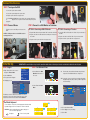
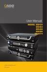
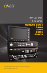
Quick Start Guide
QS Series Network DVRs
with H.264 Compression
QS434 - 4 Channel DVR
QS464 - 4 Channel DVR
QS408 - 8 Channel DVR
QS206 - 16 Channel DVR
IMPORTANT! This walkthrough will allow you to test your cameras and connections before you mount them.
Before You Get Started
A: Gather Your Components.
B: Unpack the box...
You will need:
1. A 19” or larger VGA PC monitor and VGA cable OR a television of any size.
Check the contents against the items shown in this poster. If you
notice any damage or missing components, please contact Q-See
Customer Support at www.Q-See.com/Support
2. A surge protector
We STRONGLY recommend that you use one that has the following specifications:
• UL-1449 Rated
• Clamping voltage of 330 or lower
• Joule rating of at least 400
• Response time of 10 nanoseconds or less
3. A power screw driver/drill to mount your cameras.
Your DVR can be controlled using the included USB mouse, remote control or the function keys on the front of the unit. For the purposes of this guide, we will be giving instructions using the mouse. Because this
guide covers several models in the QS series of DVRs, components in photos may not exactly match those on your particular mode.
Note:
This poster is intended to help you get your Q-See security system up and running. There are many additional features which can be
customized to your specific needs. More information and instructions are available in the User Manual included on the CD that came
with your system or available for download from our website at www.Q-See.com.
For information on how to configure your system for remote monitoring on the Internet or on your smartphone, please refer to the
Remote Monitoring Guide also included on the accompanying CD.
Be sure to register your product!
Visit www.Q-See.com, click SUPPORT
and then select the online registration form.
Complete the product registration form to receive
warranty/technical support benefits and to be notified of product updates
and free downloadable firmware updates to your DVR.
Connect the Devices
STEP 1 Turning on the DVR
1. Connect the power cable to the DVR
2. Connect the power adapter to the power cable.
3a. Plug the power cable into a surge protector
b. The QS408 and QS464 have a power switch on the rear panel which must
be flipped to the “On” positon. All other models will power up when
plugged in.
STEP 2 Connect Mouse
3a
3b
STEP 3 Connect to a VGA Monitor or Television
Plug the mouse into the USB port on the rear of the
DVR.
NOTE: the USB port on the front of the DVR is used for
backing up video files.
OPTION A: Connecting a VGA PC Monitor
OPTION B: Connecting a Television
1. Plug the VGA cable into the port marked “VGA” on the back of the DVR.
2. Plug the other end of the VGA cable into the similar port on the back of the monitor.
1. Connect the BNC-to-RCA cable to the “Video Out” port on the back of
the DVR.
2. Plug the other end into the RCA “Video In” port on the television.
3. Plug the television’s power cable into a surge protector.
3. Plug the monitor’s power cable into the surge protector.
NOTE: If you do not see the cursor on your display, roll the mouse scroll wheel forward or backward until it appears.
Initial Set Up
IMPORTANT! You must follow these steps to enter the current date and time in order to effectively use the video search function described at the end of this guide.
STEP 4 Log In
1. Right-click anywhere on the screen to
bring up the Shortcut Menu.
2. Click on Main Menu.
3.The Log In Screen will appear
4.Click Apply to log in.
DEVICE ID :
USER NAME :
PASSWORD
MAIN MENU
KEY LOCK
CHN SWITCH
DIGITAL ZOOM
VIDEO SEARCH
PTZ
MUTE
MANUAL REC
STOP REC
U S E R RLOOT
G IANT I O N
000000
admin
(000000)
:
APPLY
STEP 5 Set Date and Time
3a.
1. Click on Basic in the Main
Menu Bar at the bottom of
the screen.
BASIC
SEARCH
HDD
To enter numbers or characters, click the appropriate field and a virtual
keyboard will appear. Click on a character to enter it into the field.
BLUE TAB Switches keyboard between numbers and upper or
lower case letters if appropriate.
Enter. Closes keyboard.
ADVANCE
EXIT
3b. You may also choose to set the time zone along with enabling
Daylight Savings Time (DST) to allow your DVR to adjust the
time automatically.
3aDATE
TIME
EXIT
The Virtual Keyboard
BASIC
2. Click on Time in the Basic
Menu.
LANG
1 2 3 4 123
5 6 7 8
9 0
A
H
O
V
B
I
P
W
C
J
Q
X
D
K
R
Y
TIME
C
J
Q
X
BASIC
VID/AUD
1 2 3 4 123
5 6 7 8
9 0
A B
I
1 2 3 4 H 123
5 6 7 8O P
V W
9 0
B
E F G AABC
L M NH I
S T UO P
V W
Z
PSWD
D a E bF
K h L iM
R o S pT
Y vZ w
C
J
Q
X
cG
jN
qU
x
D
K
R
Y
07/14/2011
07:29:04
SAVE DATE AND TIME
TIME
The Admin account is the default account and does not have a
password. You may create a password and other user accounts
using the Password menu as described in the User Manual.
Backspace
RECORD
Enter the date, time and desired formats using the virtual
keyboard. Click individual numbers to change them.
EXIT
E F G ABC
L M N
S T U
Z
dABC
e f g abc
k l m n
r s t u
y z
b c d e f g abc
a b c d e f g aabc
h i j k l m nh i j k l m n
o p q r s t uo p q r s t u
3b
DST
TIME SETUP
DATE
TIME
4 ZONE
FORMAT
FORMAT
24HOURS
0
OFF
DEFAULT
4. Click on Save Date and Time.
5. Click on Apply to save your settings.
6. Click on Exit.
MM/DD/YY
APPLY
EXIT
Camera Set Up
STEP 6 Connecting the Cameras
1. Connect the BNC and power leads on the camera to the matching connectors on the power and
video cable.
3. Plug one of the power leads on the power splitter into the power lead on the power and video cable.
NOTE: The male power end fits into the matching power lead on the camera.
5.Connect the single end of the power splitter to the power adapter.
2. Connect the BNC connector on the other end of the cable to any of the Video In ports on the back of
the DVR.
6. Plug the power adapter into a surge protector. You should now see a live video feed from each of
your cameras.
1
2
4. Repeat for each camera included with this package to ensure proper connection and function.
3
4
5
6
You may now mount your
cameras.
REPEAT
Operation
STEP 7 Video File Search
This DVR is configured to record when motion is
detected by default.
1. Click on Search in the Main Menu Bar.
TYPE
ALL
FILE LIST
00:00:00
S E A R CH
CH
TIME
SIZE
TYPE
BAK
01 07:55:53-07:57:17
4 . 7 M Normal
01 07:57:19-07:59:23
6 . 7 M Alarm
01 08:00:36-08:01:47
3 . 8 M Alarm
01 07:59:25-08:00:33
01 08:01:47-08:02:26
01 08:02:26-08:08:15
3 . 7 M Alarm
2 . 2 M Normal
1 8 . 3 M Alarm
a
2. To search your recordings:
FIRST
PRE
NEXT
LAST
ALL
OTHER
BACKUP
EXIT
a. Select the date to search.
b. Click the Search button.
If there are recordings on a given
day, that date will be highlighted.
c. Select the date in the calender
and the hour blocks below
will indicate when a recording
was made. Green indicates a
regular recording while red is
an alarm (motion detection)
event recording.
d. Click File List to view a list of
recordings.
e. Click on the desired recording
to begin playback.
CHN
ALL
b
RECORD SEARCH
07/14/2011
DATE
RECORD STATE
SEARCH
09:07
PLAY
c
JUL. 01 02 03 04 05 06 07 08 09 10 11 12 13 14 15 16
17 18 19 20 21 22 23 24 25 26 27 28 29 30 31
14TH
00
08
16
01
09
17
02
10
18
03
11
19
04
12
20
FILE LIST
05
13
21
d
06
14
22
07
15
23
3. Double click on the event you wish to review and it will begin
replaying. The Playback Control Bar will appear below the video,
allowing you to control the playback. It operates like a standard
video player.
Digital
Zoom
Slow
Advance
(1/2, 1/4, 1/8)
ALL
SEARCH
CH
TIME
SIZE
TYPE
BAK
01 07:55:53-07:57:17
4.7M Normal
01 07:57:19-07:59:23
6.7M Alarm
01 08:00:36-08:01:47
3.8M Alarm
01 07:59:25-08:00:33
01 08:01:47-08:02:26
01 08:02:26-08:08:15
3.7M Alarm
2.2M Normal
18.3M Alarm
e
Volume
MUTE
(2x, 4x, 8x)
FILE LIST
00:00:00
Pause
EXIT
Rewind
TYPE
Viewing
Mode
(Click to change)
Play
Fast Forward
(2x, 4x, 8x)
FIRST
PRE
NEXT
LAST
ALL
OTHER
BACKUP
EXIT
Questions or Comments? Contact Us
WEBSITE
Learn more about Q-See and our products, register your system and find accessories
online at www.Q-See.com
SUPPORT
24/7 Technical Resources • Live Chat (M-F 9-5 PST)
www.Q-See.com/Support
31
Exit
Playback