1
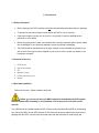
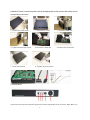
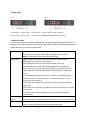
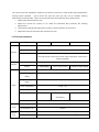
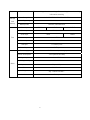
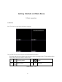
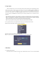
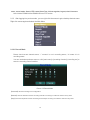
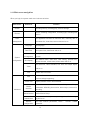
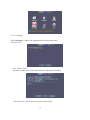
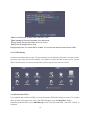
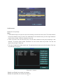
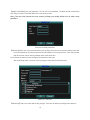
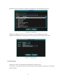
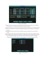
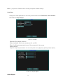
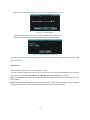
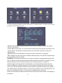
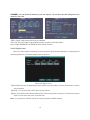
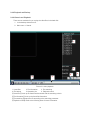
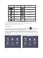
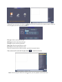
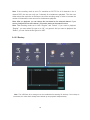
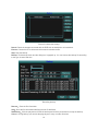
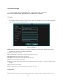
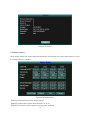
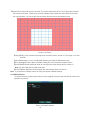
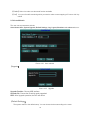
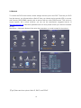
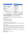
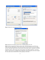
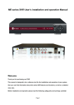
User Manual
Model: ES00M140, ES00M180
Version 1.C
1
Before You Begin
1 Introduction .................................................................................................................... 3
1.1 Safety Information……………………………………………………………………... 3
1.2 Contents of the box .............................................................................................. 3
1.3 Hard disk installation ............................................................................................ 4
1.4 Front panel ........................................................................................................... 4
1.5 Rear panel ............................................................................................................ 5
1.6 Mouse control …………………………………………………………………………5
1.7 Remote Controller Operation…………………………………………………………………….6
1.8 Audio and Video Input/Output Connections……………………………………………………..6
2 Basic operation ……………………………………………………………………………….10
2.2 Login System ...................................................................................................... 11
2.3 Main Menu .......................................................................................................... 11
2.4 System setup ............................................................................................... 14
2.4.1.3 Hard Drive Manage.…………………………………………………………….…16
2.4.2 Account………………………………………………………………………….17
2.4.5 Record ...................................................................................................... 22
2.4.6 Playback and Backup ............................................................................... 25
2.6 Network ........................................................................................................ 35
2.7 Web/Remote View ....................................................................................... 36
3 Appendix ……………………………………………………………………………………...38
3.1 Network Security Setting……………………………………………………………..38
3.2 Connection Setting .……………………………………………………………..……39
2
1. Introduction
1.1 Safety Information
•
Before setting up the DVR, carefully read all the documentation that came with your package.
•
To prevent fire and shock hazard, never expose the DVR to rain or moisture.
•
If the power supply is broken, do not try to fix it by yourself. Contact a qualified service
technician or your retailer.
•
Before using the product, make sure all cables are correctly connected and the power cables
are not damaged. If you detect any damage, contact your dealer immediately
•
The DVR should be operated only by the type of power source indicated on the label. If you
are not sure of the type of power supplied to your home or office, consult your dealer or the
local power company
1.2 Contents of the box
1.
2.
3.
4.
5.
6.
DVR device
Quick Start Guide
CD
Remote Control
Power and Power cord
Mouse
1.3 Hard disk installation
Before the first use,please install the hard disk.
Before you can record onto your HDD it should be formatted by the DVR system,
because standard PC formatting is not compatible. The format process can take several
minutes.
Your HDD should be installed inside the DVR. Please connect the(Hard Disk (HDD) in the following
way. Screw the HDD into the HDD brackets or DVR base. All necessary cables are included in the
package with the DVR. Use the instructions that came with the hard drive for exact wiring and
3
installation. Please connect the power cable to the appropriate socket, and the data cables to their
corresponding connectors.
1. Loosen the cover screw
2. Remove the cover
4. Tighten the hard disk screw
5.Connect the data wire
7. Cover the machine
8. Tighten the cover screw
3. Insert the hard disk
6.Connect the power wire
1.4 Front panel
(1) IR remote receiver (2) Record indicator light (3) Power indicator light (4) ESC (5) Left / Up / Down / Right / Menu/ Enter
4
1.5 Rear panel
4CH
8CH
(1) Video inputs
(2) BNC outputs
(3) Audio input
(4) Audio output
(5) USB
(6) Network
(7) Power supply
(8) VGA output
(9) Power Switch (ES00M140, ES00M180 without this switch)
1.6 Mouse Control
You can use a mouse to operate the DVR as well. The mouse operates just like a mouse on a
Windows PC. Please connect the mouse tone of the USB connectors (#5) in the back panel and
please note that you can hot-plug the mouse.
Right clicking
In live display mode, right clicking will either display or hide the tool bar.
In main menu or sub menu mode, right clicking will exit current menu.
Note: the settings will not be saved after right clicking.
Left clicking
When in menu unlock mode in the tool bar left click on the SYSTEM
SETTINGS icon to enter into the main menu.
After entering the main menu, left clicking will enter sub menus.
On [detail files] menu mode, left clicking will playback one recording file.
By left clicking you can select values in edit boxes or pull-down menus The
system supports Chinese character inputs, special symbols, numbers and
letters.
On the playback interface left clicking can control the >> forward function, <<
reverse function, >> I Slow play function, I > frame play function, > Play
function, and X exit function.
You can left click to adjust color control bar, volume control bar and screen
control bar.
On the main menu, sub menu or playback view, you can left click “x” to exit the
current menu.
You can left click to change the status box of a check box in the motion
detection area.
Double clicking
On the live view or playback video, double-clicking will maximize the screen.
left key
Double clicking on the maximized screen will return it to the multi camera view.
Mouse drag
In the Motion Detection setting interface, you can left click to drag
Mouse, and drag the frame to set the motion detection area.
5
Use the mouse to select menu items.
1.7 Remote controller operation
Serial
number
Name
Function
1
Multi-window
button
Same function as Multi-window button in the front
panel
2
Numeric button
3
【Esc】
4
Direction button
Same function as direction button in the front panel
5
Record control
Control the record
6
Record mode
Same function as “Record mode”
7
ADD
8
FN
Code input/number input/channel switch
Same function as【Esc】button in the front panel
Input the number of DVR to control it
Assistant function
1.8 Audio and Video Input/Output connections
1.8.1 Video input connections
The video input port is BNC connector plug. The demand of input signal is PAL/NTSC
BNC(1.0VP-P,75Ω).
The video signal must be accorded with the state standard which has the high signal to noise
6
ratio, low aberration and low interference. The image must be clear and has natural color in the
appropriate brightness.
Make sure the video signal stable and in good condition
The video should be installed in the appropriate location where is away from backlighting and low
illumination or adopts the better backlighting and low illumination compensation.
The ground and power supply of the video and the DVR should be shared and stable.
Make sure the transmission line stable and in good condition
The video transmission line should adopt high quality coaxial pair which is chosen by the
transmission distance. If the transmission distance is too far, it should adopt shielded twisted pair,
video compensation equipment and transmit by fiber to insure the signal quality.
The video signal line should be away from the electro magnetic Interference and other
equipments signal lines. The high voltage current should be avoided especially.
Make sure the connection stable and in good condition
The signal and shield lines should be firm and connected in good condition which avoid false and
joint welding and oxidation.
1.8.2 Video output connections and options
The video output is divided into PAL/NTSC BNC(1.0VP-P,75Ω) and VGA output(selective
configuration).
When replace the monitor by the computer display, there are some issues to notice.
1, Do not stay in the turn-on state for a long time.
2, Keep the computer display normal working by demagnetizing regularly.
3, Stay away from the electro-magnetic Interference.
TV is not a good replacement as a video output. It demands reducing the use time and control
the power supply and the interference introduced by the nearby equipments strictly. The creepage of
low quality TV can lead to the damage of other equipments.
1.8.3 Audio signal input
Audio port is RCA connection.
The input impedance is high so the tone arm must be active.
The audio signal line should be firm and away from the electro magnetic Interference and
connected in good condition which avoid false and joint welding and oxidation. The high voltage
current should be avoided especially.
1.8.4 Audio signal output
Commonly the output parameter of DVR audio signal is greater than 200mv 1KΩ (BNC) which
7
can connect the low impedance earphone and active sound box or other audio output equipments
through power amplifier. If the sound box and the tone arm can not be isolated, howling
phenomena is often existed. There are some methods to deal with the above phenomena.
1. Adopt better directional tone arm.
2. Adjust the sound box volume to be under the threshold that produces the howling
phenomena.
3. Use fitment materials that absorb the sound to reduce reflection of the sound.
4. Adjust the layout of the sound box and the tone arm.
1.9 Technical parameters
Type
System
4ch
8ch
16ch
Main processor
High performance embedded microprocessor
Operation system
Embedded LINUX operation system
System resource
synchronous multi-channel recording, synchronous multi-channel
sub-code stream, synchronous multi-channel playback, synchronous
network operation
Operation interface
16 bit true color graphical menu interface, mouse operation supportive
Interface
display
¼ image display
1/4/8/9 image display
1/4/8/9/16 image display
Video standard
PAL 625line,50 f/s; NTSC 525 line,60 f/s
Surveillance image
PAL, D1(704x576);NTSC, D1(704x480)
quality
Playback image
PAL,D1(704×576);NTSC, D1(704*480)
quality
Video
Video compression
H.264 mp
Video control
6 options
Recording speed
100/120fps (D1)
200/240fps (CIF),
400/480fps CIF
50/60fps D1
Audio
Record
And
Motion detect
192(12×16) detection areas, multiple sensitivity
Audio compression
G711A
Bi directional Talk
Support
Recording mode
manual > alarm > motion detect > timing
Playback
Any channels playback, multiple channels playback
8
Playback
Search mode
Time searching, calendar searching, affair searching, channel searching,
information searching
Space Occupation
Audio: 28.8MB/H Video:25~450MB/H
And
Recording storage
Hard disk, network
backup
Backup mode
Network, USB flash Drive
Storage
Video input
4 BNC
8 BNC
Video output
2 BNC, 1 VGA
Audio input
Port
Other
16 BNC
1 RCA
1 RCA
Audio output
1 RCA
Network port
RJ45 10M/100M
USB port
2* USB2.0 ports
Hard disk port
1 SATA port
Power supply
12V/2A external power supply
Power consumption
<15W (without hard disk)
Working temperature
0° ~ + 55°C
Working humidity
10%-90%
Air pressure
86kpa-106kpa
Size
260*200*43mm
Weight
2kg(without hard disk)
Installation
Desktop
.
9
Getting Started and Main Menu
2. Basic operation
2.1 Preview
Note: The button in gray display indicates nonsupport.
You can right click mouse to choose the switch between the windows.
The system date, time and channel name are shown in each viewing window. The surveillance video
and the alarm status are shown in each window.
1
Recording status
3
2
Motion detect
4
Audio
?
Table of Preview: icon
10
No Video
2.2 Login System
When the DVR boots up, the user must login and the system provides the corresponding functions
with the user privilege. There are three user settings. The names are admin, guest and default and
these names have no password. Admin is the super user privilege; guest and default’s permissions are
preview and video playback. User admin and guest’s password can be revised, while their permissions
can’t be revised; user default is the default login user whose permission can be revised but not its
password.
Note: Password protection: If the password is continuous wrong three times, the alarm will start.
Note: If the password is continuous wrong five times, the account will be locked. (Through
reboot or after half an hour, the account will be unlocked automatically).
Note: For your system security, please modify your password after first login.
2.2.1 In preview mode you can right click the mouse to get a desktop shortcut menu.
Right click the mouse again, and you will see the following:
Input your username and password and select OK.
Note: The default password for admin is blank when you receive the new DVR.
2.3 Main Menu
2.3.1 Desktop Shortcut Menu
In preview mode you can right click mouse to get a desktop shortcut menu. The menu includes: main
11
menu, record mode, Search, PTZ control, Start Tour, Volume regulate, Logout, view1/4 screens.
Note: Neither ES00M140 and ES00M180 have PTZ function
2.3.2 After logging into preview mode, you can right click the mouse to get a desktop shortcut menu.
Right click mouse again and select the Main Menu
2.3.2.1 Record Mode
Please check current channel status: “○” means it is not in recording status, “●” means it is in
recording status.
You can use desktop shortcut menu or click [main menu]> [recording function]> [recording set] to
enter the recording control interface.
Picture 3.5 Record Mode
【Schedule】Record according to the configuration.
【Manual】Click the all button and the according channel is recording no matter the channel in any state.
【Stop】Click the stop button and the according channel stops recording no matter the channel in any state.
12
2.3.3 Main menu navigation
When you login, the system main menu is shown as below.
Main menu
Sub menu
Search
recording look-up, recording play, video file storage
Set the recording configuration, recording type, recording time
Record
section
HDD
Set appointed hard disk as read-write disc, read-only disc or
management
redundant disc, clear data, resume date and so on
Language
Set language.
Date/Time
Set system time, data format and so on.
Account
management
System
configuration
Function
GUI display
Modify user, team or password. Add user or team. Delete user
or team.
Set channel name, video time, color setting, preview time,
preview channel, record status, alarm status and so on.
Set resolution, video standard, tour time, and output adjust
Video
and so on.
Exit
Mail
Version Info
Motion
Advanced
detection
Mobile Monitor
Automatic
maintenance
Network
configuration
Return last lever menu.
Send email to addresses which you have ordered when alarm
or alarm linkage happening。
Display software version and build date.
Set motion detect alarm channel, sensitivity, area, linkage
parameters: defending time section, alarm output, screen hint,
recording
Mobile Monitor Setup.
Set automatic reboot system , system upgrade, default settings,
log and so on.
Set basic network parameters, DHCP 、 PPPOE 、 DDNS
parameter
13
Exit
Exit
2.3.3.1
Return last lever menu.
Exit main menu and display Monitor.
When the Main Menu appears, click the system icon in the main menu shown below:
2.4 System setup
Set all the system parameters by clicking each icon .i.e. Language, Date/Time, Account, GUI
Display, and Video. After setting all the parameters, click “Exit” on the System Menu.
->
14
->
2.4.1.1 Language
Click [Language] Æ Select your language from the drop down menu.
Then click “OK”.
2.4.1.2 Date / Time
【System time】Set the system date and time on the Date/Time Menu
Enter the month, date, and time using the virtual keypad
15
【Date format】Choose the data format: YMD, MDY, DMY.
【Date Separator】Choose list separator of the data format.
【Time Format】Choose time format: 24 hour or 12 hour
【DST】Click for Daylight Saving Time.
Daylight savings time “On” means DST is enabled. You can setup the start time and end time of DST.
2.4.1.3 HDD Manage
Configure and manage the hard disk. The menu displays current hard disk information: hard disk number,
input port, type, status and overall capability. The operation include hard disk format, recover (resume
HDD to default status). Choose the hard disk and click the right function button to execute.
->
2.4.1.4Format Hard Drive
If you install a new hard drive (HDD), you must format the HDD before using it to record. To format a
drive, go back to the main menu, click > the HDD Manage Icon on the Main Menu screen
Select the preferred HDD > on the HDD Manage screen. Click【Format Disk】 then Click 【OK】 to
complete.
16
2.4.2 Account
Manage the user privilege
Note:
1. The character length is 8 bytes at most for the following user and user team name. The blank ahead or
behind the character string is invalid. The middle blank in the character string is valid. Legal characters
include: letter, number, underline, subtraction sign, dot.
2. There is no limit in the user and user group. You can add or delete the user group according to user
definition. The factory setup include: user\admin. You can set the team as you wish. The user can
appoint the privilege in the group.
3. The user management include: group/ user. The group and user name can not be the same. Each user
only belongs to one group.
Picture 4.9 Account
【Modify User】Modify the existed user attribute.
【Modify Group】Modify the existed team attribute.
17
【Modify Pwd】Modify the user password. You can set 1-6 bit password. The blank ahead or behind the
char string is invalid. The middle blank in the char string is valid.
Note:The user who possess the user control privilege can modify his/her own or other users
password
Picture 4.10 Modify Password
【Add user】Add a user in the team and set the user privilege. Enter the menu interface and input the user
name and password. Choose the team and choose whether cover using the user. Cover using means
that the account can be used by multiple users at the same time.
Once choose the team the user privilege is the subclass of the team.
We recommend that the common user’s privilege is lower than the advanced user.
Picture 4.11 add user
【Add Group】Add a user team and set the privilege. There are 36 different privileges: shut down the
18
equipment, real time surveillance, playback, recording setup, video file backup and so on.
Picture 4.12 Add Group
【Delete User】Delete the current user. Choose the user and click delete user button.
【Delete Group】Delete the current group. Choose the group and click delete group button.
Picture 4.13 Delete Group
2.4.3 GUI Display
Configure the video output parameters including the front output mode.
Front output:In the local preview mode include: channel title, time display, channel title, record status,
and alarm status.
19
Picture 4.14 GUI Display
【Channel Title】Click the channel name modify button and enter the channel name menu. Modify the
channel name. The 16 Chinese characters and 25 letters are supportive.
【Preview Time】means the selective state. Display the system data and time in the surveillance window.
【preview Channel】means the selective state. Display the system channel number in the surveillance
window.
【Record Status】means the selective state. Display the system recording status in the surveillance
window.
【Alarm Status】means the selective state. Display the system alarm status in the surveillance window.
【Color Setting】Set the selective image parameters (current channel for single window display and cursor
place for multi-window display). You can press “Set” button and enter the interface. The image
parameters include: tonality, brightness, contrast, saturation. You can set different parameters.
Picture 4.15 Color Setting
20
Note:If you press the “Default” button, all config will replace to default settings.
2.4.4 Video
Configure the video parameters In the local preview mode include: Resolution, Video Standard,
Tour Time and Output Adjust.
Picture 4.16 Video
【Resolution】Set display resolution.
【Video Standard】Set the video standard as PAL or NTSC.
【Tour Time】Set the patrol switch interval. The set range is 5-120 seconds.
【Output Adjust】
Adjust TV output area parameters. You can enter [main menu]> [System]> [Video]> [Output adjust].
Picture 4.17 Output Adjust
Audio Adjust
21
Adjust volume regulate parameters. You can use the desktop shortcut menu.
Picture 3.17 Audio Adjust
【Volume regulate】You can set the volume regulate value from 0 to 100.
【Advanced】If you press this button then you will see picture as follow.
Picture 3.18 Audio matches Channal
You can match any or all channels which you want to match. But only one channel audio output valid
at the same time.
2.4.5 Record
Set the recording parameters in the surveillance channel.
The User needs to install and format a HDD, and set all the recording parameters before recording.
There are 2 record modes: Scheduled, and Manual, along with Stop for (No record).
Note: Record frame rate, resolution, quality and hard drive space will affect the total recording time of
DVR system.
Note: All parameters will affect the recording time length for HDD. Recording higher quality images at
a higher frame rate will result in a shorter recording time for the same size HDD.
22
—>
—>
To set the recording parameters click the “Record icon” on the Main Menu. You will set the recording
parameters on the following screen.
【Resolution】Indicates the setup resolution and code rate for recording. There are four options:
D1.HD1, CIF and QCIF.
【Frame Rate】In this section, you can choose the recording frame rate (frames per second) for the
current channel. The higher the record frame rate, the more natural movement you will see in
playback mode.
【Quality】There are several options: Choose the one that is the best for your purpose.
【REC. Mode】There are three options: Schedule, Manual and Stop. Click the REC. Mode field and
you will be taken to the menu below.
SCHEDULE: This setup function allows you to create a schedule for recording tasks throughout the
week, so that only certain selected events are actually recorded on the HDD. For example, you may
setup the system to record non-stop throughout your normal business hours, making it a
schedule-triggered recoding at lunch time (that means no recording will be performed unless an
alarm event happens), night time being set to motion detection recording with certain hours made
more secure with the combined schedule and motion detection triggered recording, finally making it
more sophisticated by specifically setting a no-record time slot when you stay in the office alone in the
wee hours of weekday mornings. You can setup any schedule that fits your needs..
Please note that manual recording overrides all record settings and will be carried on until stopped by
the operator.
23
CHANNEL: You can select all channels or just one channel. You can also copy the settings from one
channel to the other.
—>
【REC. Size】It will pack by the time you selected.
Click “OK” and “OK” again in each following menu to return to the Main Menu.
Note: Neither ES00M140 or ES00M180 have “Alarm” function.
2.4.5.1 Region Cover
When the video image is influenced by the environment such as bad brightness or reaching the set
sensitivity parameter, the camera mask function is turned on.
Picture 4.3 Region Cover
【Channel】Choose the corresponding channel number to set the channel. Choose the all option to set the
entire channels.
【Switch】You can select ON or OFF status as this channel.
【Region Cover】When this channel status as ON, Click set and enter the set area. The area has 4 region
areas. You can move the cursor to set the area.
Note:If you press the “Default” button, all config will replace to default settings.
24
2.4.6 Playback and Backup
2.4.6.1Search and Playback
There are two methods for you to play the video files in the hard disk.
1、 In the desktop shortcut menu.
2、 Main menu -> Search.
1
2
4
5
6
Picture 3.6 video playback
1. Listed files
2. File information
3. File searching
4. File backup
5. Operation hint
6. Playback control
【Listed files】Look up the listed files that accord with the searching criteria.
【File information】Look up the found file information.
【File searching】Search the file according to the searching parameter.
【Playback control】Refer to the following sheet for more information.
25
3
Button
/
Function
Button
Function
Play/pause
Backward
Stop
Slow play
Fast play
Previous frame
Next frame
Previous file
Next file
Circulation
Full screen
Table 3.2 Playback control key
Note: Frame by frame playback is only performed in the pause playback state.
【Operation hint】Display the function of the cursor place.
Special functions:
Accurate playback:Input time (h/m/s) in the time column and then click play
button. The system
can operate accurate playback according to the searching time.
Local zoom:When the system is in single-window full-screen playback mode, you can drag your
mouse in the screen to select a section and then left click mouse to realize local zoom. You can right
click mouse to exit.
The DVR supports live recorded playback, and time search. Select Main Menu > Playback > Search
—>
—>
26
—>
【Search】Use the Quick click button
virtual keypad, then click the search button
and enter the time period you want to search using the
File type: Set the searching file type.
HDD type: Set the searching hdd type.
Channel: Set the searching channel.
Start Time: Set the searching time scan.
End Time: Set the searching time scan.
Enter the time period you want to search, and click the search button
Then, select one file, and click the play button
or double click the file
Note: Record setup will affect the total channels you can playback at the same time.
27
Note: If the recording mode is set to D1 resolution at 30 FPS for all 4 channels in the 4
channel DVR, the user can only use 2 channels for simultaneous playback. The User can
either reduce the resolution or the frame rate of the recording setup in order to increase the
number of channels the user can use for simultaneous playback.
Note: After you playback, you can change the time based on the selected channel. If you
want to change both time and channel, you need to start over the search function.
Note: The recording mode set to both “Regular” and “Detect”. If you want to playback
“Regular”, you must select file type to be “All”, not general. And you want to playback the
“Detect”, you can choice the file type to be “MD”.
2.4.6.2 Backup
->
Note: The USB flash drive storage must be installed before starting file backup. If the backup is
terminated, the video that’s already been backed up can playback independantely.
28
Picture 3.8 detect the storage
Detect: Detect the storage connected with the DVR such as hard disk or universal disk.
Erasure: Choose the file to delete and click erasure to delete the file.
Stop: Stop the backup.
Backup: Click backup button and the dialog box is popped up. You can choose the backup file according
to the type, channel and time.
Recording backup
Remove:Clear the file information.
Add:Show the file information satisfying the set file attributes.
Start/Pause:Click the play button to start the backup and click the pause button to stop the backup.
Cancel:During backup you can exit the page layout to carry out other functions.
29
2.5 Advanced Setup
You can configure the Advanced parameters, In the local preview mode include:
Mail, Version, Motion Detect, Mobile Monitor, Auto Maintain and Network.
2.5.1 Mail
If the Motion Detect is turned on and are taken, send an email about the moion detect information
(Text as Title only) to appointed address.
Picture 4.18 Email
SMTP server: Email server address. It could be an IP address or domain name. Domain name can be
translated only it is the correct DNS configuration.
Port: Email server port number.
SSL: Decide whether using Secure Socket Layer protocol to login.
User Name: Apply the email server user name.
Password: Input the password corresponding to the user.
Sender: Set the email sender address.
Receiver: Send the email to appointed receivers when the alarm is turned on. You can set three receivers
at most.
Title: You can set as you wish.
Note: Email alert only send text massage same as title user wiite.
2.5.2 Version
Display the basic information such as hardware information, software edition, and issue data and so on.
30
Picture 4.19 Version
2.5.3 Motion Detect
When system detects the motion signal that reaches the set sensitivity, the motion detect alarm is on and
the linkage function is turned on.
Picture 4.20 Motion Detect
【Channel】Choose the set motion detect channel.
【Status】means that the motion detect function is on or off.
【Sensitivity】Choose in the six options according to the sensitivity.
31
【Region】Click setup and enter the set area. The area is divided into NTSC 12x16. Green block means
the current cursor area. Yellow block means the dynamic detect defensive area. Black block means
the unfenced area. You can set the area as follows, Drag the mouse and draw the area.
Picture 4.21 Region
【Delay】Delay a few moments and stop when the alarm state is turned off. The range is 10~300
seconds.
【Delay】When alarm is over, recording will last some seconds(10~300sec),then stop.
【Show message】Pop the alarm information dialog box in the local host computer screen.
【Send EMAIL】Means sending an email to user when the motion detect alarm is turned on.
Note: Set in the [Net Service] and send email.
【Buzzer】Buzzer will alarm two times when the motion detect alarm is turned on.
Note:If you press the “Default” button, all config will replace to default settings.
4.6.4 Mobile Monitor
To visit the device by mobile, please make a router mapping of this port and use CMS to monitor and
operate it by protocol.
Picture 4.22 Mobile Monitor
32
【Enable】Select it to make sure abnormal function workable
【Port】 It’s a port of mobile monitoring which you need to make a router mapping of if want to visit it by
mobile
2.5.4 Auto Maintain
The user can set parameters include:
Auto reboots time, System Upgrade, Default Settings, Log, Logout, Shutdown and reboot and so on.
Picture 4.23 Auto maintain
【Upgrade】
Picture 4.25 Upgrade
Upgrade Position: Choose USB interface.
Upgrade file: Choose the file which needs upgraded.
Note: After Upgrade operation,the DVR will reboot.
【Default Settings】
The system restore to the default setup. You can choose the items according to the menu.
33
Picture 4.24 Restore
【Log】
Look up system log according to the set mode.
Log information include: system operation, configuration operation, data management, alarm affair,
recording operation, user management, file management and so on. Set the time section to look up
and click the look up button. The log information will display as a list. (one page is 128 items) Press
Page up or Page down button to look up and press delete button to clear all the log information.
Picture4.26 LOG
【logout】Quit the menu. Offer password next entrance.
【reboot】Quit the system. Reboot up the system.
34
2.6 Network
To connect the DVR to the internet, certain settings must be input to the DVR. To access your DVR
from the internet, you will need either a Static IP from your internet service provider (IPS) or a router
with Dynamic DNS (DDNS) capacity and an account with an online DDNS service. This service is
country specific, but in many countries, you can use the manufacturer suggested service id
http://www.dyndns.org. If the below parameters are not clear, please contact your network consultant
for help.
Main Menu > Advanced> Network, then enter the parameters you need to setup for the network
—>
—>
【Type】there are three options: Static IP, DHCP, and PPPoE
35
—>
【Media Port】Transfers video data between client and device, default is 34567
【Web Port】Sets up the port of IE browser via HTTP,default is 80
【IP Address】Set up the IP address
【Subnet Mask】Set up the Subnet mask
【Gateway】Set up the default gateway
【DNS】Set up the domain name sever
. This will take you to the following screen.
【DDNS】Click the button
2.7 Web/ Remote View
Open IE browser, input the correct IP address and port number, and you will see the following screen.
Input the correct name and password, and then click the Login button.
Note: Make sure all the active controls for internet security on your PC are enabled. For IE, you can
go to Tools > Internet Options > Security.
Note: The default user ID is “admin”. Default password is blank
Note: RESTRICTION:
To ensure the PC‘s stable interfacing with the DVR, we recommend Windows XP or Windows Vista
operation system, and IE 6.0, IE 7.0 browsers.
36
After you login, you will see the following screen. Click the Ok button
If you want to exit at this point, please select the Logout button
37
[Main Stream] This choice will provide the user with the best image to view but will affect the frame rate
the user can receive.
[Extra Stream] This choice will provide the user with a lower grade image; however, the picture will run
smoother due to the higher frame rate.
[Auto Prompt] After logging in using the web viewing mode, the screen will auto prompt the window of
stream choice to user when you select the function.
3. Appendix
3.1 Network Security Setting
Prior to controlling installation, please program the network security level by using the following
operations:
(1) Open the IE browser and click [Tools→ Internet Options].
(2) Choose the “Security” tab in the dialogue box.
38
(3) Click “Customization level” to enter into the security Setting
Set the ActiveX control and pluggable unit. Select the following options
√ ActiveX control auto-prompting
√ Run the script of the ActiveX control which is marked to safely implement the script.
√ Implement initialization and run the script of the ActiveX control which is not marked to safely
implement the script.
√ Binary system and the script behavior
√ Download the unsigned ActiveX control
√ Download the signed ActiveX control
√ Perform the ActiveX control and pluggable unit
It’s extremely importation to “enable” the items above.
Prompt: Before control installation, please turn off the fire wall and the anti-virus software.
4. Connection Setting
The remote access for the hard disk recording machine should be carried out through the network. In
the local area network connection, the IP address of the client-side computer must be on the same
network section with that of the hard disk recording machine. While in the wide area network
connection, just ensure that two sides can access the public network, and connect through the IP
address or the dynamic domain name. The following will mainly focus on connecting and setting the
method for the local area network.
Step 1: Right click on “Network neighborhood” and click “Attribute” in the ejected menu to open the
“Network connection”.
Step 2: Double click to open “Local connection”.
Step 3: Click “Attribute”.
39
Step 4: Double click “Internet protocol (TCP/IP)”.
Step 5: Examine the IP address, subnet mask, and default gateway on the PC.
Step 6: Set the corresponding IP address, subnet mask, and default gateway on the DVR. If the
subnet mask and default gateway on the DVR are the same as those of the PC, then the IP address
must be in the same network section but cannot be the same as the used one. Otherwise, it will cause
IP address conflicts. Take the figure above as an example, the IP address should be: 192.168.0.X,
wherein, X cannot be 40 or 1 (including other IP addresses currently being used), and cannot surpass
255, the subnet mask is 255.255.255.0, and the gateway is 192.168.0.1.
40
5 FAQ and maintenance
5.1 FAQ
If the problems are not listed, please contact the local service or call the HQ service. We are willing to
offer the service.
1.
The DVR cannot boot up normally.
Possible reasons are as follows:
a)
The power supply is not correct.
b)
Switch power supply line is not in good connection.
c)
Switch power supply is damaged.
d)
The program updating is wrong.
e)
The hard disk is damaged or the hard disk lines are broken.
f)
The front panel is damaged.
g)
The main board of the DVR is damaged.
2. The DVR reboots automatically or stops working after boot up a few minutes.
Possible reasons are as follows:
a)
The input voltage is not stable or too low.
b)
The hard disk is damaged or the hard disk lines are broken.
c)
The power of the switch power supply is low.
d)
Frontal video signal is not stable.
e)
Bad heat radiator or too much dust or bad running circumstance for the DVR.
f)
The hardware of the DVR is damaged.
3. System cannot detect hard disk.
Possible reasons are as follows:
a)
The hard disk power supply line is not connected.
b)
The cables of the hard disk are damaged.
c)
The hard disk is damaged.
d)
The SATA port of main board is damaged.
4. There are no video outputs in single channel, multiple channels and all channels.
Possible reasons are as follows:
a)
The program is not matched. Please update the program.
b)
The image brightness is all 0. Please restore the default setup.
c)
There is no video input signal or the signal is too weak.
d)
The channel protection or the screen protection is set.
e)
The hardware of the DVR is damaged.
5. Real-time image problems such as the image color or the brightness distortion.
41
Possible reasons are as follows:
a)
When using the BNC output, the option between the N mode or PAL mode is wrong and the
image becomes black and white.
b)
The DVR is not matched the monitor impedance.
c)
The video transmission distance is too far or the loss of the video transmission line is too
large.
d)
The color and brightness setting of the DVR is wrong.
6. I cannot find the video files in local playback mode.
Possible reasons are as follows:
a)
The data line of the hard disk is damaged.
b)
The hard disk is damaged.
c)
Update the different program with the origin program files.
d)
The video files to look up are covered.
e)
The recording is not on.
7. The local video is not clear.
Possible reasons are as follows:
a)
The image quality is too bad.
b)
The reading program is wrong. Reboot up the DVR.
c)
The data line of the hard disk is damaged.
d)
The hard disk is damaged.
e)
The hardware of the DVR is damaged.
8. There is no audio signal in the surveillance window.
Possible reasons are as follows:
a)
It is not an active tone arm.
b)
It is not an active sound box.
c)
The audio lines are damaged.
d)
The hardware of the DVR is damaged.
9. There is audio signal in the surveillance window but mo audio signal in the playback
state.
Possible reasons are as follows:
a)
Setting issues: the audio option is not chosen.
b)
The according channel is not connected with the video.
10. The time is wrong.
Possible reasons are as follows:
a)
Setting is wrong.
b)
The battery is in bad connection or the voltage is too low.
c)
The oscillation is damaged.
11. The DVR cannot control the PTZ.
Possible reasons are as follows:
a)
There is something wrong with the frontal PTZ.
b)
The setting, connection or the installation of the PTZ decoder is not correct.
42
c)
The connections are not correct.
d)
The PTZ setting of the DVR is not correct.
e)
The protocols of the PTZ decoder and the DVR are not matched.
f)
The address of the PTZ decoder and the DVR are not matched.
g)
When multiple decoders are connected, the far port of the PTZ decoder line A(B) must
h)
connect a 120 Ω resistance to reduce the reflection otherwise the PTZ control is not stable.
The distance is too far.
12. The motion detect is not working,
Possible reasons are as follows:
a)
The time range set is not correct.
b)
The motion detect area set is not correct.
c)
The sensitivity is too low.
d)
Limited by some hardware edition.
13. I cannot login via web or CMS.
Possible reasons are as follows:
a)
The systems are windows 98 or win me. We recommend updating to windows 2000sp4 or
higher Version or installing the software for low edition.
b)
ActiveX is hold back.
c)
The version is not exceeded dx8.1. Update the display card driver.
d)
Network connection failure.
e)
Network setting issues.
f)
Invalid password or user name.
g)
The CMS is not matched the DVR program version.
14. The image is not clear or there is no image in network preview state or video file playback
state.
a)
Possible reasons are as follows:
b)
Network is not stable.
c)
The user machine is resource limited.
d)
Choose the play-in-team mode in the network setup of DVR.
e)
The region shelter or channel protection is set.
f)
The user has no surveillance privilege.
g)
The real-time image of the hard disk recording machine itself is not clear.
15. Network connection is not stable.
a)
Possible reasons are as follows:
b)
Network is not stable.
c)
IP address is conflicted.
d)
MAC address is conflicted.
e)
The net card of the DVR is bad.
16. There is something wrong with the USB backup or writing a CD.
a)
Possible reasons are as follows:
b)
The rewritable machine and the hard disk are shared the same data lines.
43
c)
The data is too much. Please stop recording and backup.
d)
The data exceeds the backup storage.
e)
The backup equipment is not compatible.
f)
The backup equipment is damaged.
17. The keyboard cannot control the DVR.
a)
Possible reasons are as follows:
b)
The serial port of the DVR is not set correctly.
c)
The address is not correct.
d)
When multiple transformers are connected, the power supply is not large enough. Please
give each transformer individual power supply.
e)
The distance is too far.
18. Alarm cannot be recessional.
a)
Possible reasons are as follows:
b)
The setting of the alarm is not correct.
c)
The alarm output is turned on manually.
d)
The input machine is damaged or the connections are not correct.
e)
There are some problems for specific program edition, Please update the program.
19. Alarm is not working.
a)
Possible reasons are as follows:
b)
The setting of the alarm is not correct.
c)
The connection of the alarm is not correct.
d)
The alarm input signal is not correct.
e)
An alarm is connected with two loops synchronously.
20. The remote controller is not working,
a)
Possible reasons are as follows:
b)
The remote control address is not correct.
c)
The remote control distance is too far or the angle is too large.
d)
The battery is used up.
e)
The remote controller or the front panel of the recording machine is damaged.
21. The storage time is not enough.
a)
Possible reasons are as follows:
b)
Front Videocon quality is bad. The lens is too dirty. The Videocon is in backlighting
installation.
c)
The hard disk capability is not enough.
d)
The hard disk is damaged.
22. The downloading files cannot play.
a)
Possible reasons are as follows:
b)
There is no media player.
c)
There is no DX8.1 software or higher edition.
d)
There is no DivX503Bundle.exe file to play AVI video files.
e)
The DivX503Bundle.exe and ffdshow-2004 1012 .exe files must be installed in the windows
44
xp system.
23. I cannot remember the advanced code or network code in the local menu operation.
Please contact the local service or call the HQ service. We will offer the service according the
machine type and the program edition.
4.2 Maintenance
1
Please brush printed circuit boards, connectors, fans, machine box and so on regularly.
2
Please keep the grounding well done to prevent the video or audio signal interfered and the
DVR from static or inductive electricity.
3
Do not pull out the video signal line or RS-232 port or RS-485 port with the power on.
4
Do not use the TV in the local video output port(VOUT) of DVR. It will damage the video
output circuit easily.
5
Please keep the DVR away from heat resource.
6
Please keep the DVR ventilated for better heat radiator.
Please check the system and maintain regularly.
45