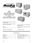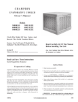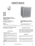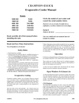
1
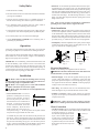
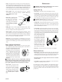
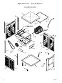
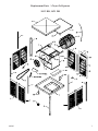
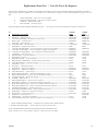
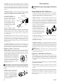
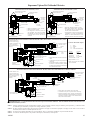
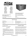
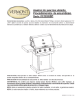
Industrial/Commercial
EvaporativeCoolerManual
Models
75/85DD
75/85SD
95DD
95SD
10/12DD
10/12SD
14/21DD
14/21SD
Circlethemodelofyourcoolerandrecordthe
serialnumberbelow.
ReadCarefullyAllOfThisManualBefore
InstallingTheUnit.
Encierre con un circulo el modelo de su enfriador y
escribe el número de serie abajo.
Lea Con Cuidado Todo Este Manual Antes De
Instalar La Unidad.
Serial #
ReadAndSaveTheseInstructions
Vea el Español en el interior.
Número De Serie
TableOfContents
Safety Instructions ...........................................................................2
Operation..........................................................................................2
Installation Instructions................................................................ 2-3
Maintenance Section ........................................................................3
Electrical Wiring Diagrams..............................................................4
Troubleshooting ...............................................................................5
Warranty ...........................................................................................5
Parts Drawing (Dibujo de Piezas) - 10/12SD, 14/21SD ..................6
Parts Drawing (Dibujo de Piezas) - 10/12DD, 14/21DD ................7
110525
Parts List (Lista de Piezas) - 10/12, 14/21 .......................................8
Parts List (Lista de Piezas) - 75/85, 95 ............................................9
Parts Drawing (Dibujo de Piezas) - 75/85DD, 95DD....................10
Parts Drawing (Dibujo de Piezas) - 75/85SD, 95SD .....................11
Motor Specifications (Especificaciones del Motor) - 75/85DD, 95DD .10
Motor Specifications (Especificaciones del Motor) - 75/85SD, 95SD ..11
Motor Specifications (Especificaciones del Motor) - 10/12, 14/21....12
General Specifications (Especificaciones Generales) ...................12
Spanish (Instrucciones en Español) ......................................... 13-16
7-10
SafetyRules
1. Read instructions carefully.
2. Disconnect all electrical service that will be used for the unit before
you begin the installation.
3. Electrical hook up should be done by a qualified electrician, so
that all electrical wiring will conform to your local standards.
4. For a maximum safety precaution, make sure cooler cabinet is
properly grounded to a suitable ground connection.
• Ductwork. See the General Specification table for the duct opening dimension for your specific cooler. For down discharge units
models 10/12DD and 14/21DD, the duct must go inside the opening.
Size these ducts slightly smaller than the duct opening in the cooler.
On 75/85DD and 95DD models the duct may go to the inside or
outside of the duct flange. The side discharge units have a 1 inch
flange. Size these ducts larger than the duct opening to fit over the
flange of these units.
Note:Curbsarenotprovided.Theinstallerisresponsiblefor
providingcurbsorothermeanstosupportthecooler.
MotorInstallation
5. Cooler must be connected to proper line current, voltage and cycle,
as stamped on cooler motor and pump motor specification plate.
6. Do no allow pump to tip over and become submerged.
7. Always DISCONNECT POWER before installing unit or
performing any maintenance.
Operation
• Mountmotor. Slide the heads of the provided carriage bolts into
the slots of the adjustable channels. Slide these channels sideways
in the slotted holes to align with the holes in the motor base and to
align the motor shaft with the blower pulley. Mount the motor to
the motor mount using these carriage bolts and the washers and nuts
provided (see Fig. 2). Make sure all bolts are securely tightened.
• Installpulley. Install the adjustable motor pulley so that it aligns
with the blower drive pulley (see Fig. 3) and tighten set screw. See
page 3 for instructions on adjusting pulley.
For the best cooling performance, if the pads are dry, pre-wet the pads
by running the pump for a few minutes before starting the blower.
Motor
Pulley
These coolers may also be used without water for ventilation purposes.
When outside air is cool (for example, at night) or when humidity is
high the water pump can be turned off.
IMPORTANT: To cool efficiently, you must exhaust the stale or used
air from the building. Open windows or doors or use exhaust fans
located away from the cooler and in the direction you wish to cool
the air. The air will flow in the direction of the exhaust openings. A
common guide for the amount of exhaust opening needed is to have
at least 2 square feet of opening per 1000 CFM.
Installation
CAUTION:Makesurethatthemountingsurfaceisstrong
enoughtosupporttheoperatingweightofthecoolerwheninuse.
(For operating weight, see Specification Table.)
CAUTION:Neversupplypowertocooleruntilinstallation
iscompleteandunithasbeentestedforrigidity.
CAUTION:Makesureallboltsaresecurelytightenedbefore
startingthecooler.
• Louvered Side Panels. The louver
panels have a locking latch on each top
corner to secure it in place. To remove
the louvered panel you will need to
loosen the latch screws on either side of
the panel. Loosen the screws enough
Fig. 1
to rotate the latch handle, but do not
remove completely. Rotate the latch
handle towards the center of the louvered panel (see fig. 1). Tilt the top of the louver panel outward
away from the top pan and lift out from cooler.
To reinstall the panel, first insert the bottom of the panel into the
bottom pan. Tilt the panel forward so that it rests against the top
pan. You will need to keep the latch handles rotated to the side to
keep the lock from hitting the top pan. Once the louver panel is
in place, rotate the latch handle so that the handle is facing down.
Tighten the screws to lock latch and secure panel in place.
Blower
Housing
Adjustable
Channels
Fig. 2
Blower
Pulley
Fig. 3
ElectricalInstallation
NOTE: Local building code regulations must be observed.
WARNING:Disconnectallelectricalservicethatwillbeused
forthisunitbeforeyoubegintheinstallation.
• ElectricalSupply. Cooler must be supplied with the proper line
current, voltage and frequency, as stamped on cooler motor and
pump motor specification plate. See the wiring diagrams on page
4 for typical electrical connections. NOTE: Connecting improper
voltage to motor will void motor warranty.
• Wiresizing. The conductor sizes are to be determined by motor
loads and length of run per national and local electrical codes.
• Switchesorcontactors. Motors require switches or contactors
of proper current capacity and should be sized and installed by a
competent electrician.
WARNING: Make sure that cooler cabinet is properly
groundedtoasuitablegroundconnectionformaximumsafety.
WaterConnection
• Overflow assembly. Remove nut and place nipple through the hole
in the pan, with the rubber washer between the pan and the head
of the drain nipple (Fig. 4). Screw on
Overflow Pipe
nut and draw up tight against bottom
of pan. Insert overflow pipe in nipple
Nipple
to retain water. Overflow pipe may be
Rubber Washer
removed to drain pan when necessary.
Bottom Pan
A garden hose may be screwed on the
Nut
drain nipple to drain water away from
Fig. 4
your unit.
11055
• Pump. The pump must be secured to prevent it from tipping over.
Secure the pump to the pump mounting bracket. For the 10/12 and
14/21 models, remove the mounting screw on the top of the pump
and using this same screw, secure the pump to the pump mount. To
secure the pump for the 75/85 and 95 models, slide the pump into
the slot of the pump mount and secure with the plastic retainer.
• Water Supply. Run a water supply line to the unit. The float
valve requires a 3/8 inch tube connection.NOTE:Donotuse
watersuppliedfromawater
Water Supply
softener.
Line
Mount Bracket
Float Rod
Washer
Nut
Ferrule
Nut
• Float valve. Install the float
valve to the mount bracket in
the cooler (Fig. 5) and attach
water supply line. Note: 75/85
and 95 units come with the float
valve installed. For the other
models, the float is purchased
separately.
Fig. 5
• Fillingpan. Turn on water supply and check for leaks. Allow
water to fill to within 1” of top of pan. Loosen the screw on the
float rod to adjust the float and retighten the screw.
• Watertroughs. Operate pump until pads are saturated. Check
each trough to see if water is evenly dispersed in the trough. If
they are not, loosen adjustment bolts and level trough. Retighten
bolts. Check to see that all pads are saturated with water and that
there are no dry spots or openings in the pads.
• Bleed-Off. Use of a bleed-off kit is recommended to prevent scale
build up by bleeding off small amounts of circulating water during
operation. Do not add any type of water treatment chemicals to the
water.
PulleyAndBeltAdjustments
• Pulley adjustment. With an ammeter, check the motor amperage. Adjust the pulley until the amperage draw on the motor is
just below that specified on the motor
nameplate. To adjust the pulley, loosen
the adjustment set screw and rotate the
sheave. Tighten the set screw so that
Decrease
it is over a flat area, otherwise thread
Amperage
damage will occur. To increase amperage draw, increase pulley diameter.
To decrease amperage draw, decrease
Fig. 6
pulley diameter (Fig. 6). Recheck belt
alignment.
CAUTION:Whenitisnecessarytoadjustpulley,amperage
ofmotormustbecheckedtomakecertainitdoesnotexceedthe
maximum allowed as stamped on motor specification plate. Improperpulleyadjustmentwilloverloadandburnoutmotor.
• Belt tension. Loosen the motor
mount bolts and slide the motor
back until the belt is properly
tensioned. A 3 lb. force should
deflect the belt 3/4 inches (see Fig.
7). Retighten motor mount bolts.
Do not adjust pulley to tighten
belt.
11055
3 lb.
3/4 Inches
Maintenance
WARNING:Beforedoinganymaintenancebesuretodisconnectfrompowersource.Thisisforyoursafety.
SpringStart-Up
• Belttension. Check belt tension and readjust if needed.
• Oilbearings. The blower bearings and cooler motor in this unit
should be oiled with a few drops of non-detergent 20/30 weight oil
once each year. The motor does not need oil if it has no oil lines
for oiling. Motors that have no oil lines are lifetime oiled at the
factory and require no further oiling for the life of the unit.
CAUTION:Donotoveroil. Over oiling can cause motor burn
out, due to excessive oil getting into motor winding.
• ChangePads. The pads should be replaced once or twice a season,
depending upon the length of the season. At the beginning and at
mid season a clean pad is more absorbent and efficient and will
deliver substantially more cool air.
• Cleanpump. Cleaning the pump is necessary once a year at startup. For your safety, disconnect from power source and unplug
pump. Remove the pump from the mount bracket. Remove the base
of the pump (Fig. 8). Clean the pump and turn the impeller to ensure
free operation. Remove the pump spout and check for any blockage.
After cleaning, reinstall the
base onto the pump. Reattach the pump to the mount
Remove
in the cooler to ensure that
the pump will not overturn.
Do not forget to replace the
spout and water delivery tube
onto the pump outlet. The
pump has automatic reset
thermal protection. Pump
Fig. 8
will operate normal again
after obstruction is cleared.
• Bleedoff. Check bleed-off valve to be sure it is not clogged.
WinterShutDown
• Drainwater. Always drain all of the water out of the cooler and
water supply line when not in use for prolonged periods, and particularly at the end of the season. Keep the water line disconnected
from both the unit and water supply so that it does not freeze.
• Disconnectfrompowersupplywhennotinuseforextended
periodsof time.
• Coverunit. To protect the life of the finish, a cover for the unit is
suggested in extended periods of non use.
By following the operating, installation, and maintenance suggestions as outlined, you can get many years of efficient and satisfactory service from your cooler. In the event additional information
is desired, your dealer will be more than glad to assist you in every
possible way.
Fig. 7
TypicalElectricalWiringDiagrams
120Volt,1PhaseElectricSupply
Disconnect Switch At Cooler
See Notes 1 & 2
240Volt,1PhaseElectricSupply
Disconnect Switch At Cooler
See Notes 1 & 2
Control Contacts
See Note 4
L
H
P
L1
N
Gnd
N
Gnd
Fuses
See Note 1
120V
120 Volts
1 Phase
Power Supply
208 or 240V
1 Phase
Power Supply
Main Disconnect
See Note 1
Cooler Cabinet
See Note 3
• 115 Volt single phase blower motor.
• 120 Volt pump motor.
• Diagram shown for two speed motor.
Low speed circuit drawn with dashed
lines is not required for single speed.
Pump Motor
Fuses
See Note 1
Transformer
Cooler Cabinet
Equipment
Ground
Blower Motor
L1
L2
Gnd
L2
Gnd
Main Disconnect
See Note 1
See Note 3
Control Contacts
See Note 1
L
H
P
Equipment
Ground
Blower Motor
Pump Motor
• 230 Volt single phase blower motor.
• 120V pump motor shown. Transformer may be omitted when a 240V
pump is used with a 240V supply
• Diagram shown for two speed motor.
Low speed circuit drawn with dashed
lines is not required for single speed.
208,240,or480Volt,3PhaseBlower&120Volt1PhasePump&ControlElectricSupply
Motor Starter With
Overload Protection Sized
To Match Motor Full Load
Current
See Note 1
Gnd
L1
L2
L3
Control Contacts
See Note 4 H
Main Disconnects
See Note 1
L1
120V
N
1 Phase
Gnd
Power Supply
P
N
Gnd
Fuses
See Note 1
T3
T2
T1
Gnd
Disconnect Switch At
Cooler
See Notes 1 & 2
208, 240, or 480V
3 Phase
Power Supply
Disconnect Switch At Cooler
See Note 1&2
Cooler Cabinet
See Note 3
Pump Motor
Equipment
Ground
Blower Motor
• Three phase single speed blower motor
• Three pole motor starter with overload
protection
• 120V single phase control and pump shown.
If 240V control and pump are to be used, then
both legs of power supply must be fused.
TypicalControlContacts
FunctionandConnection
L
P
H
L1
-
Low Fan
Pump
Hi Fan
Supply Power
Function
Off
Pump Only
Hi-Cool
* Low-Cool
Hi-Fan
* Low-Fan
Connection
None
L1-P
L1-H
L1-L & L1-P
L1-H
L1-L
* Omit for single speed blower motor
208,240,or480Volt,3PhaseBlowerElectricSupplyWithTransformerForPump&Control
Gnd
L1
L2
L3
Motor Starter With
Overload Protection
Sized To Match Motor
Full Load Current
See Note 1
Control Contacts
See Note 4
Main Disconnect
See Note 1
H
P
120
V
Disconnect Switch At Cooler
See Notes 1 & 2
T3
T2
T1
Gnd
208, 240 or 480V
3 Phase
Power Supply
Fuses
See Note 1
Transformer
See Note 1
Cooler Cabinet
See Note 3
Disconnect Switch At Cooler
See Notes 1 & 2
Pump Motor
Equipment
Ground
Blower Motor
• Three phase single speed blower motor.
• Three pole motor starter with overload protection.
• 120V single phase pump powered by a transformer.
Transformer may be omitted when 240V control &
pump are used with a 240V supply.
WARNING: Electrical hookup should be performed by a qualified electrician. All electrical wiring must conform to national and
local standards.
NOTE1. All switches, motor starters, transformers, fuses, junction boxes, receptacles, receptacle boxes, cover plates, and conductors shall be supplied by the
installer and must comply with local and national electrical codes.
NOTE2. The national electric code requires a disconnect switch located at equipment if the main disconnect at equipment controller is not visible from the equipment. If more than one disconnect is used they must be mounted adjacent to one another.
NOTE3. A receptacle for a NEMA 5-15P plug is required for 120V recirculating pump and a receptacle for a NEMA 6-15P plug for 230V pump.
NOTE4. The control contacts may be part of a switch, thermostat or other control device.
11055
TroubleshootingGuide
Problem
Failure to
start or no
air delivery
PossibleCause
1. No electrical power to unit
• Fuse blown
• Circuit breaker tripped
2. Belt too loose or tight
3. Motor overheated
•
•
•
•
Belt too tight
Blower bearings dry
Motor bearings dry
Motor pulley diameter too
large
4. Motor locked
Inadequate
air delivery
with cooler
running
1. Insufficient air exhaust
2. Belt too loose
3. Pads plugged
4. Insufficient water flow
over pads
Musty or
unpleasant
odor
1. Stale or stagnate water in
cooler
2. Pads not wetting properly
• Trough holes clogged
• Pump not working properly
• Insufficient water flow
over pads
Remedy
1. Check power
• Replace fuse
• Reset breaker
2. Adjust belt tension
3. Determine cause of overheating
• Adjust belt tension
• Oil blower bearings
• Oil motor bearings
• Adjust pulley to correct
diameter
4. Replace motor
1. Open windows or doors
to increase air flow
2. Adjust belt tension or
replace if needed
3. Clean pads
4. Clean water distribution system and trough
openings
1. Drain pan and clean
pads
2. Check water distribution
system
• Clean
• Replace or clean pump
(Unplug)
• Clean distribution system and trough openings
Problem
PossibleCause
Remedy
Motor
cycles on
and off
1. Low voltage
2. Excessive belt tension
3. Blower shaft tight or
locked
4. Bearings dry
5. Motor pulley diameter
too large causing motor
overload
6. Faulty motor
1. Check voltage
2. Adjust belt tension
3. Oil or replace bearings
(Disconnect unit)
4. Oil bearings
5. Adjust pulley so full load
ampere rating of motor
is not exceeded
6. Replace motor
Noisy
1. Bearings dry
2. Wheel rubbing blower
housing
3. Loose parts
1. Oil bearings
2. Inspect and realign (Disconnect unit)
3. Tighten loose parts
Inadequate
cooling
1. Inadequate exhaust in
house
2. Pads not wet
1. Open windows or doors
to increase air flow
2. Check water distribution
system
• Clean pads
• Repack pads
• Clean
• Replace or clean pump
(Unplug)
•
•
•
•
Excessive
humidity in
house
Pads plugged
Open spots in pads
Trough holes clogged
Pump not working properly
1. Inadequate exhaust
1. Open doors or windows
Register your product online at: www.championcooler.com/index.php/cooler-warranty-registration
LimitedWarranty
This warranty is extended to the original purchaser of an evaporative cooler installed and used under normal conditions. It does not cover damages incurred
through accident, neglect, or abuse by the owner. We do not authorize any person or representative to assume for us any other or different liability in connection with this product.
TermsAndConditionsOfWarranty
For Five Years from date of purchase, we will replace the base assembly if water leakage should occur due to rust out.
For One Year from date of purchase, we will replace any original cabinet component which fails due to defect in material or factory workmanship only.
ExclusionsFromTheWarranty
We are not responsible for replacement of cooler pads. These are disposable components and should be replaced periodically. We are not responsible for
any incidental or consequential damage resulting from any malfunction.
We are not responsible for any damage received from the use of water softeners, chemicals, descale material, plastic wrap or if a motor of a higher horsepower
than what is shown on the serial plate is used in the unit.
We are not responsible for the cost of service calls to diagnose cause of trouble, or labor charge to repair and/or replace parts.
HowToObtainServiceUnderThisWarranty
Contact the Dealer where you purchased the evaporative cooler. If for any reason you are not satisfied with the response from the dealer, contact the
Customer Service Department: 5800 Murray Street, Little Rock, Arkansas 72209. 1-800-643-8341. E-mail: [email protected], Web: www.
championcooler.com.
Thislimitedwarrantyappliestooriginalpurchaseronly.
11055
5
ReplacementParts/ Piezas De Repuesto
10/12SD,14/21SD
11055
ReplacementParts/ Piezas De Repuesto
10/12DD,14/21DD
11055
ReplacementPartsList/ Lista De Piezas De Repuesto
All parts may be ordered from your dealer, but not directly from the factory. Be sure that you furnish the following information on all orders. /
Todas las partes pueden ser pedidas con su concesionario, pero no directamente a la fábrica. Incluya toda la información siguiente con su pedido:
1.
2.
3.
4.
Cooler serial number / Número de serie de la unidad
Description and part number / Descripción y número de parte
Cooler size / Tamaño de la unidad
Date of purchase / Fecha de compra
Failure to supply all of this information will delay your order. / El no proporcionar toda esta información resultará en una demora.
No.
N°
1.
2.
3.
4.
5.
6.
7.
8.
9.
10.
11.
12.
13.
14.
15.
16.
17.
18.
19.
20.
21.
22.
23.
24.
25.
26.
27.
28.
29.
30.
31.
32.
33.
Description/ Descripción
10/12SD
Top Pan / Bandeja Superior ----------------------------------------------------------218116-037
Bottom Pan / Bandeja Inferior --------------------------------------------------------218116-038
Front Panel / Panel Del Frente--------------------------------------------------------318116-002
Louvered Side Assembly / Montaje De La Reja Lateral --------------------------322116-004
Corner Post, Right / Poste De Esquina, Derecho-----------------------------------218003-001
Corner Post, Left / Poste De Esquina, Izquierdo -----------------------------------218003-003
Center Post / Poste Central ------------------------------------------------------------218002-001
Water Trough / Canal De Agua -------------------------------------------------------226003-001
Aspen Pads / Filtros De Paja ---------------------------------------------------------110097
Pad Retainers / Soporte Para El Filtro ----------------------------------------------3PW-8
Water Distributor Assembly / Sistema Del Distribuidor De Agua ---------------3D-11
Nozzle, Water Distributor / Boquilla Del Distribuidor De Agua -----------------110569
Pump Screen / Malla Para La Bomba -----------------------------------------------281001-001
Blower Wheel / Rueda -----------------------------------------------------------------110750
Shaft, Blower Wheel / Eje De La Rueda --------------------------------------------110158
Bearings, Blower Wheel Shaft / Cojinetes Del Eje De La Rueda ----------------110358
Channel Retainer Support / Retendedor De Canal --------------------------------214007-007
Motor Mount Support / Soporte Para El Montura Del Motor--------------------214116-003
Motor Mount Crossbrace / Travesaño De La Montura Del Motor --------------214001-009
Motor Mount Adjustable Channel / Montura Ajustable Del Motor -------------214112-002
Bearing Mount Support / Soporte Para Los Cojinetes ----------------------------214116-001
Blower Housing / Caja De La Rueda ------------------------------------------------320116-001
Pulley, Blower Wheel / Polea De La Rueda ----------------------------------------110281
Cut-Off Plate / Placa Externa ---------------------------------------------------------318112-004
Air Baffle / Bafle Del Aire -------------------------------------------------------------220116-002
Pump Mount / Soporte De La Bomba ------------------------------------------------214003-023
Drive Belt / Correa ---------------------------------------------------------------------110232
Over Flow Assembly / Montaje De Desagüe ---------------------------------------3OA-1
Tube, Water Delivery / Tubo De Agua -----------------------------------------------310717
Deflecter Strip / Tira De Desviación -------------------------------------------------222116-002
Float Mount / Soporte Del Flotador -------------------------------------------------Water Distributer Support Bracket / Soporte Del Distribuidor De Agua--------218002-003
Latch Assembly (2 Per Side) / Montaje Cerradura (2 Por Cada Panel) --------318124
10/12DD
218116-001
318116-025
322116-004
218003-001
218003-003
218002-001
226003-001
110097
3PW-8
3D-12
110569
281001-001
110750
110158
110358
214007-002
214116-003
214001-006
214112-002
214116-005
320116-001
110281
318112-004
220116-002
214003-023
110231
3OA-1
310717
222116-002
214003-010
318124
14/21SD
216117-005
216117-006
318117-002
322117-004
218003-002
218003-004
218002-002
226003-002
110098
3PW-9
3D-13
110569
281001-001
110751
110159
110358
214007-008
214117-003
214001-007
214112-003
212103-001
320117-001
110298
318112-003
220116-005
214003-023
*110219
3OA-1
310717
222117-002
218002-003
318124
14/21DD
216117-001
316117-002
322117-004
218003-002
218003-004
218002-002
226003-002
110098
3PW-9
3D-14
110569
281001-001
110751
110159
110358
214007-004
214117-003
214001-007
214112-003
212102-001
320117-001
110298
318112-003
222119-001
214003-023
*110219
3OA-1
310717
222117-002
214003-010
318124
* 14/21SD & 14/21DD Coolers require 2 belts / Los modelos 14/21SD y 14/21DD requiren dos correas.
NOTE: Standard hardware items may be purchased from your local hardware store.
NOTA: Artículos de uso corriente pueden comprarse en la ferretería de su localidad.
11055
ReplacementPartsList/ Lista De Piezas De Repuesto
All parts may be ordered from your dealer, but not directly from the factory. Be sure that you furnish the following information on all orders. /
Todas las partes pueden ser pedidas con su concesionario, pero no directamente a la fábrica. Incluya toda la información siguiente con su pedido:
1.
2.
3.
4.
Cooler serial number / Número de serie de la unidad
Description and part number / Descripción y número de parte
Cooler size / Tamaño de la unidad
Date of purchase / Fecha de compra
Failure to supply all of this information will delay your order. / El no proporcionar toda esta información resultará en una demora.
No.
N°
1.
2.
3.
4.
5.
5A.
6.
7.
8.
8A.
9.
10.
11.
12.
13.
14.
15.
16.
17.
18.
20.
22.
23.
24.
25.
27.
28.
29.
30.
31.
32.
34.
35.
36.
37.
38.
75/85DD
Description/ Descripción
95DD
Top Pan / Bandeja Superior ----------------------------------------------------------------------------------220905-005
Bottom Pan / Bandeja Inferior --------------------------------------------------------------------------------320908-004
Louvered Side Assembly / Montaje De La Reja Lateral --------------------------------------------------322115-005
Water Trough / Canal De Agua -------------------------------------------------------------------------------226003-004
Aspen Pads / Filtros De Paja ---------------------------------------------------------------------------------110096
*Glass Fiber Pads / Filtros De Vidrio ------------------------------------------------------------------------*110129-004
Pad Retainers / Soporte Para El Filtro ----------------------------------------------------------------------3PW-7
Corner Post, With Float Hole / Poste De Esquina, Con Agujero Para Flotador-----------------------224003-011
Corner Post, No Float Hole / Poste De Esquina, Sin Agujero Para Flotador --------------------------224003-019
Corner Post, For Pump Mount / Poste De Esquina, Para Montar Bomba ------------------------------224003-044
Cut-Off Plate / Placa Externa ---------------------------------------------------------------------------------320102-002
Blower Housing / Caja De La Rueda ------------------------------------------------------------------------322115-002
Blower Wheel / Rueda -----------------------------------------------------------------------------------------110749
Shaft, Blower Wheel / Eje De La Rueda --------------------------------------------------------------------110157
Bearings, Blower Wheel Shaft / Cojinetes Del Eje De La Rueda ----------------------------------------110357
Pulley, Blower Wheel / Polea De La Rueda ----------------------------------------------------------------110280
Drive Belt / Correa ---------------------------------------------------------------------------------------------**
Float Valve / Válvula Del Flotador---------------------------------------------------------------------------FL 3/8
Pump Mount / Soporte De La Bomba ------------------------------------------------------------------------218001-031
Pump Screen / Malla Para La Bomba -----------------------------------------------------------------------281001-001
Tube, Water Delivery / Tubo De Agua -----------------------------------------------------------------------310716
Water Distributor Assembly / Sistema Del Distribuidor De Agua ---------------------------------------3D-7
Holder, Water Distributor / Soporte Para El Distribuidor De Agua -------------------------------------110574
Over Flow Assembly / Montaje De Desagüe ---------------------------------------------------------------3OA-1
Air Baffle / Bafle Del Aire -------------------------------------------------------------------------------------220116-002
Bearing Mount Support / Soporte Para Los Cojinetes ----------------------------------------------------214118-001
Motor Mount Crossbrace / Travesaño De La Montura Del Motor --------------------------------------214001-005
Motor Mount Support, Right / Soporte Para El Montura Del Motor, Direcho ------------------------214118-004
Motor Mount Support, Left / Soporte Para El Montura Del Motor, Izquierdo ------------------------214118-004
Channel Retainer Support / Retendedor De Canal --------------------------------------------------------218115-023
Motor Mount Adjustable Channel / Montura Ajustable Del Motor -------------------------------------214112-004
Bleed-Off Kit / Equipo De La Válvula De Desahogo -----------------------------------------------------310586
Deflecter Strip / Tira De Desviación -------------------------------------------------------------------------222115-003
Front Panel / Panel Del Frente--------------------------------------------------------------------------------Pump Retainer / Retenedor De La Bomba ------------------------------------------------------------------110714
Latch Assembly (2 Per Side) / Montaje Cerradura (2 Por Cada Panel) --------------------------------318124
75/85SD
95SD
220905-004
220906-004
322115-005
226003-004
110096
*110129-004
3PW-7
224003-018
224003-045
320102-002
322115-002
110749
110157
110357
110280
**
FL 3/8
218001-031
281001-001
310716
3D-8
110574
3OA-1
220116-006
214115-006
214001-005
214115-002
214115-002
218115-001
214112-004
310586
222115-003
320115-001
110714
318124
* Used for 95DD and 95SD units only. / Utilizado por los modelos 95DD y 95SD solamente.
** See Motor Specification table. / Véase la table de especificaciones del motor.
NOTE: Standard hardware items may be purchased from your local hardware store.
NOTA: Artículos de uso corriente pueden comprarse en la ferretería de su localidad.
11055
ReplacementParts/ Piezas De Repuesto
75/85DD,95DD
Motor Specifications / Especificaciones Del Motor
Model
Modelo
HP
C.V.
Motor
Motor
Phase
Fase
Speed
Velocidad
Volts
Voltios
Shaft (in.)
Eje (pulgadas)
Drive Belt
Correa
3/4
*110455
*110480
110461
1
1
3
1
2
1
115/208-230
230
208-230/460
5/8
1/2
5/8
110217
(4L-830)
1
*110457
*110458
+110462-9
1
1
3
1
2
1
115/208-230
230
208-230/460
5/8
5/8
7/8
110217
(4L-830)
1-1/2
*110459-1
+110463-9
1
3
1
1
115/208-230
208-230/460
5/8
7/8
110217
(4L-830)
2
*110460-1
+110464-9
1
3
1
1
115/208-230
208-230/460
5/8
7/8
110217
(4L-830)
~110306-1
110299
3
+110465-9
3
1
208-230/460
1-1/8
110218
(4L-850)
110304 (0 - 0.6" Static)
110300 (0.2 - 1.0" Static)
75/85 DD
95 DD
Motor Sheave
Polea Del Motor
†110279-002 (0 - 0.7" Static)
†110279-004 (0.3 - 0.8" Static)
~110308 (0 - 0.7" Static)
~110279-003 (0.3 - 0.8" Static)
~110279-003 (0 - 0.8" Static)
~110306-1 (0.6 - 1.0" Static)
110302 (0 - 0.8" Static)
110299 (0.6 - 1.0" Static)
~110279-003 (0 - 0.7" Static)
~110306-1 (0.4 - 1.0" Static)
110302 (0 - 0.7" Static)
110299 (0.4 - 1.0" Static)
* Resilient mounted motors / Motores con bases resistentes.
+ EPACT Motors / Motores de buen rendimiento.
† For motors with 1/2 in. shaft / Para motores con el eje de 1/2 pulgadas de diámetro.
~ For motors with 5/8 in. shaft / Para motores con el eje de 5/8 pulgadas de diámetro.
10
11055
ReplacementParts/ Piezas De Repuesto
75/85SD,95SD
Motor Specifications / Especificaciones Del Motor
=Model
Modelo
HP
C.V.
Motor
Motor
Phase
Fase
Speed
Velocidad
Volts
Voltios
Shaft (in.)
Eje (pulgadas)
Drive Belt
Correa
3/4
*110455
*110480
110461
1
1
3
1
2
1
115/208-230
230
208-230/460
5/8
1/2
5/8
110217
(4L-830)
1
*110457
*110458
+110462-9
1
1
3
1
2
1
115/208-230
230
230/460
5/8
5/8
7/8
110217
(4L-830)
1-1/2
*110459-1
+110463-9
1
3
1
1
115/208-230
230/460
5/8
7/8
110217
(4L-830)
~110279-003 (Static < 0.6")
~110306-1 (Static > 0.2")
110302 (Static < 0.6")
110299 (Static > 0.2")
2
*110460-1
+110464-9
1
3
1
1
115/208-230
230/460
5/8
7/8
110217
(4L-830)
~110306-1
110299
75/85 SD
95 SD
*
+
†
~
Motor Sheave
Polea Del Motor
†110279-002 (Static < 0.6")
†110279-004 (Static > 0.3")
~110308 (Static < 0.6")
~110279-003 (Static > 0.3")
~110279-003 (Static < 0.8")
~110306-1 (Static > 0.6")
110302 (Static < 0.8")
110299 (Static > 0.6")
Resilient mounted motors / Motores con bases resistentes.
EPACT Motors / Motores de buen rendimiento.
For motors with 1/2 in. shaft / Para motores con el eje de 1/2 pulgadas de diámetro
For motors with 5/8 in. shaft / Para motores con el eje de 5/8 pulgadas de diámetro.
11055
11
Motor Specifications / Especificaciones Del Motor
Model
Modelo
10/12 DD
10/12 SD
14/21 DD
14/21 SD
HP
C.V.
Motor
Motor
Phase
Fase
Speed
Velocidad
Volts
Voltios
Shaft (in.)
Eje (pulgadas)
Drive Belt
Correa
Motor Sheave
Polea Del Motor
1
*110457
*110458
+110462-9
1
1
3
1
2
1
115/208-230
230
208-230/460
5/8
5/8
7/8
110231
(4L970)
~110308
110309
1 1/2
*110459-1
+110463-9
1
3
1
1
115/208-230
208-230/460
5/8
7/8
110231
(4L970)
110302 (Static < 0.6)
110299 (Static > 0.4)
~110279-003 (Static < 0.6)
~110306-1 (Static > 0.4)
2
*110460-1
+110464-9
1
3
1
1
115/208-230
208-230/460
5/8
7/8
110231
(4L970)
~110306-1
110299
1
*110457
*110458
+110462-9
1
1
3
1
2
1
115/208-230
230
208-230/460
5/8
5/8
7/8
110232
(4L-980)
~110308
110309
1 1/2
*110459-1
+110463-9
1
3
1
1
115/208-230
208-230/460
5/8
7/8
110232
(4L-980)
2
*110460-1
+110464-9
1
3
1
1
115/208-230
208-230/460
5/8
7/8
110232
(4L-980)
1 1/2
*110459-1
+110463-9
1
3
1
1
115/208-230
208-230/460
5/8
7/8
110219
(B-108)
110290
~110286
2
*110460-1
+110464-9
1
3
1
1
115/208-230
208-230/460
5/8
7/8
110219
(B-108)
~110286 (Static < 0.6)
~110285 (Static > 0.4)
110290 (Static < 0.6)
110289 (Static > 0.4)
3
+110465-9
3
1
208-230/460
1-1/8
110219
(B-108)
110291
5
+110466-9
3
1
208-230/460
1-1/8
110219
(B-108)
110291 (Static < 0.6)
110304-1 (Static > 0.4)
1 1/2
*110459-1
+110463-9
1
3
1
1
115/208-230
208-230/460
5/8
7/8
110219
(B-108)
110290
~110286
2
*110460-1
+110464-9
1
3
1
1
115/208-230
208-230/460
5/8
7/8
110219
(B-108)
~110286 (Static < 0.6)
~110285 (Static > 0.3)
110290 (Static < 0.6)
110289 (Static > 0.3)
3
+110465-9
3
1
208-230/460
1-1/8
110219
(B-108)
110291
5
+110466-9
3
1
208-230/460
1-1/8
110219
(B-108)
110291 (Static < 0.5)
110304-1 (Static > 0.3)
110302 (Static < 0.5)
110299 (Static > 0.3)
~110279-003 (Static < 0.5)
~110306-1 (Static > 0.3)
~110306-1 (Static < 0.8)
~110310 (Static > 0.6)
110299 (Static < 0.8)
110307-1 (Static > 0.6)
* Resilient mounted motors / Motores con bases resistentes.
+ EPACT Motors / Motores de buen rendimiento.
~ For motors with 5/8 in. shaft / Para motores con el eje de 5/8 pulgadas de diámetro.
General Specifications / Especificaciones Generales
Model No.
Modelo
75/85 DD
95 DD
75/85 SD
95 SD
10/12 DD
10/12 SD
14/21 DD
14/21 SD
*Weight (lbs.)
Peso (libras)
Dry
Operating
Seco
Lleno
Cabinet Dimensions (in.)
Dimensiones De La Caja (pulgadas)
Height
Width
Depth
Altura
Anchura
Profundidad
Duct Opening (in.)
Abertura De Ducto (pulgadas)
Width
Height
Anchura
Altura
281
373
53 5/8
41 1/4
41 1/4
21 3/4
21 3/4
259
426
53 5/8
41 1/4
41 1/4
21 3/4
21 3/4
447
439
621
617
622
689
896
1000
53 5/8
53 5/8
61 1/4
61 1/4
50
50
62
62
50
50
62
62
26 7/8
26 7/8
31 3/4
31 3/4
26 7/8
26 7/8
31 3/4
31 3/4
*Does not include motor weight. / No incluye el peso del motor.
1
11055
LeayConserveEstasInstrucciones
ReglasDeSeguridad
1. Lea las instrucciones con cuidado.
2. Desconecte todos los servicios eléctricos que serán usados en esta
unidad antes de instalar el enfriador.
3. Las conexiones eléctricas deben ser hechas por un electricista
competente, para que todo el cableado eléctrico cumpla con los
requisitos establecidos en su localidad.
4. Para una máxima y segura precaución, debe estar muy seguro que la
caja del aparato está conectada con la tierra.
5. El enfriador debe ser conectado con el propio voltaje, corriente alterna
y ciclos, lo que se encuentran en la placa de especificaciones de la
bomba y del motor.
6. Asegure la bomba para no se vuelca en el agua.
7. Siempre CORTELACORRIENTEantes de realizar cualquier labor
de mantenimiento.
Operación
Para el mejor funcionamiento, si los filtros son secos, prenda sólo la bomba
durante unos cuantos minutos antes de prender el motor del ventilador.
menos de la abertura del enfriador. El ducto puede entrar por el interior
o el exterior del reborde de salida de los modelos 75/85DD y 95DD.
Las unidades con salida del lado tienen un reborde de 1 pulgada. El
tamaño de estos ductos debe ser más grande de la abertura del enfriador
para caber sobre el reborde.
Nota:Lossoportesparamontarelenfriadornoestánprovistos.El
instaladoresresponsableparasoportarelenfriador.
InstalaciónDelMotor
• Montarelmotor.Deslice la cabeza de los pernos provistos con cuellos cuadrados por la ranura en la montura ajustable del motor. Puede
deslizar las monturas ajustables hacia un lado u otro lado para alinear
los pernos con los agujeros en el base del motor y para alinear la polea
del motor con la polea de la rueda. Instale el motor usando los pernos
y las tuercas provistos (véase fig. 2). Asegúrese que los pernos estén
apretados seguramente.
• Instalarlapoleadelmotor. Instale la polea ajustable del motor para
que quede alineada con la polea del ventilador (véase fig. 3) y apriete
el tornillo de presión. Vea la página 14 para instrucciones de ajustar la
polea.
Polea Del
Motor
Su enfriador puede ser utilizado sin agua para proporcionar ventilación
solamente. Cuando esté fresco (por ejemplo, de noche) o cuando la
humedad es alta, la bomba de agua puede ser apagada.
IMPORTANTE: El proceso de enfriamiento por evaporación requiere
que agota el aire viejo del edificio. Abre las ventanas o puertas o utilice
los extractores de aire situados lejos del enfriador y en la dirección que
desea enfriar. El aire fluirá en la dirección de las aberturas de escape. Debe
tener a lo menos 2 pies cuadrados de abertura por cada 1000 CFM.
Instalación
PRECAUCIÓN: La superficie en que ha de colocarse el
enfriadordeberáaguantarelpesocompletodelaunidadcuando
éstaestáenfuncionamiento.(Parasaberestepeso,vealatabla
de especificaciones.)
PRECAUCIÓN: No conecte el enfriador hasta que la instalación esté completa y se haya comprobado la estabilidad del
mismo.
PRECAUCIÓN: Asegúrese que todos los tornillos estén
apretadosseguramenteantesdeprenderelenfriador.
• PanelesDelLado. Los paneles del lado tiene un cierre de fijación en
cada esquina. Para quitar el panel necesitará aflojar los tornillos del
cierre de ambos lados del panel. Afloje los tornillos bastante para girar
la manija de cierre, pero no los quite totalmente. Gire la manija de
cierre hacia el centro del panel (véase la figura 1). Incline la tapa del
panel hacia fuera de la bandeja superior y levántelo del enfriador.
Para reinstalar el panel, primero inserte la parte inferior del panel en la
bandeja inferior. Incline el panel adelante de modo que se recline contra
la bandeja superior. Necesitará mantener
las manijas de cierre giradas al lado para
que el cierre no golpea la bandeja superior.
Una vez que el panel está en el lugar, trabe
el panel girando la manija de cierre de
modo que la manija esté orientado hacia
abajo. Apriete los tornillos para sujetar el
Fig. 1
panel en el lugar.
• El sistema del ducto. Vea la tabla de
especificaciones generales para el tamaño del abertura del ducto. Para
los modelos 10/12DD y 14/21DD con salida de abajo, el ducto debe
entrar por el interior del abertura. El tamaño de estos ductos debe ser
11055
Caja De
La Rueda
Montura
Ajustable
Fig. 2
Polea Del
Ventilador
Fig. 3
InstalaciónEléctrica
NOTA: Los códigos locales de construcción deben ser observadas.
ADVERTENCIA:Desconectetodoslosservicioseléctricos
queseránusadosenestaunidadantesdeinstalarelenfriador.
• Conexióneléctrica. El enfriador debe ser conectado con el propio
voltaje, corriente de línea y frecuencia, que se encuentran en la placa
de información de la bomba y del motor. Vea las esquemas de cableado
en la página 15 para las conexiones típicas.
NOTA: El conectar el motor a voltaje impropio anulará la garantía del
motor.
• Calibredecable. La carga del motor y el longitud del cable requerido
por los códigos eléctricos nacionales y locales determinará el calibre
de cable que debe usar.
• Interruptoresycontactores. Los motores requieren interruptores o
contactores de propia capacidad de corriente. Un electricista cualificado
debe determinar su tamaño e instalarlos.
ADVERTENCIA:Compruebequelacajadelenfriadortenga
ladebidaconexiónatierraparaproveermáximaseguridad.
ConectarElAgua
• La instalación del montaje de
desagüe. Quite la tuerca y pase la
Tubo De Desagüe
boquilla por el agujero de la bandeja,
Boquilla Roscada
colocando la arandela de hule entre
Arandela De Hule
la bandeja y la cabeza de la boquilla
Bandeja
(véase fig. 4). Coloque la tuerca en la
Tuerca
boquilla y atorníllela hasta que quede
apretada contra la parte inferior de la
Fig. 4
bandeja. Inserte el tubo de desagüe en
la boquilla para retener el agua. El tubo de desagüe se puede quitar
para desaguar el agua de la bandeja cuando sea necesario. Se puede
conectar una manguera de jardín a la boquilla para desaguar el agua
hacia otra parte.
1
• LaBomba. Debe asegurar la bomba al soporte de la bomba para
evitar que incline encima. Para los modelos 10/12 y 14/21, quite la
tuerca de la tapa de la bomba y asegure la bomba al soporte usando
este tuerca. Para asegurar la bomba a los modelos 75/85 y 95, deslice
la bomba por la horquilla del soporte y asegúrela con el retenedor de
plástico.
• Elsuministrodeagua. Conecte un tubo de suministro de agua de
3/8 pulgadas en diámetro a la válvula de flotador. NOTA:Nunca
utiliceelaguasuministradodeunsuavizadordeagua.
Soporte Del
Flotador
Tubo De Abastecimiento De
Agua
Varilla Del
Flotador
Arandela
Tuerca
Ferula
Tuerca
• La válvula de flotador. Instale la válvula de flotador en el
soporte del flotador dentro del
enfriador y conecte el tubo de
agua (véase fig. 5). Nota: La
válvula de flotador está instalada en los modelos 75/85 y 95.
Necesitará comprar la válvula
de flotador por separado para
los otros modelos.
Fig. 5
• Llenar la bandeja con agua.
Permita que se llene la bandeja con agua hasta una altura de una
pulgada por debajo del borde superior de la bandeja. Ajuste el flotador
para que mantenga este nivel. Al ajustar el flotador, afloje el tornillo
de la válvula, ajuste la varilla y apriete el tornillo. Compruebe que
no escape el agua.
• Loscanalesdeagua.Ponga a funcionar la bomba hasta saturar de
agua los filtros. Luego revise cada canal para ver si la distribución
del agua es pareja. Si no es así, afloje los tornillos de ajuste y nivele
cada canal. Vuelva a apretar los tornillos. Compruebe que todos los
filtros hayan quedado saturados de agua y que no contengan áreas
secas o roturas.
• Laválvuladedesahogo. Recomendamos usar la válvula de desahogo para prevenir la formación de escama, por la segregación de
pequeñas cantidades de agua durante la operación. No agregue ningún tipo de productos químicos del tratamiento de aguas al agua.
AjustarLaPoleayLaCorrea
• Ajustarlapolea. Con un amperímetro, mide el amperio del motor.
Ajuste la polea del motor hasta que el amperio sea menos por poco
de lo que se especifica la placa de identificación del motor. Al ajustar
la polea, afloje el tornillo de ajuste con punta plana y gire la polea.
Apriete el tornillo de modo que la punta
del tornillo queda sobre el área plana, si
no, dañaría las roscas. El incrementar el
diámetro de la polea, incrementa también
Disminuir
Amperio
el amperio; el disminuir el diámetro de
la polea, disminuye también el amperio
(véase fig. 6). Vuelva a inspeccionar la
alineación de la correa.
Fig. 6
Mantenimiento
ADVERTENCIA:Antesdehacercualquiermantenimiento,
compruebe que la corriente esté desconectada. Esto es por su
seguridad.
PuestaEnMarchaEnLaPrimavera
• Cambiar los filtros. Debe cambiar los filtros de paja una o dos veces
durante cada temporada, según la duración de ésta. Al principio y
a mediados de la temporada, un filtro limpio es más absorbente y
eficiente y producirá un mayor volumen de aire fresco.
• Limpiar la bomba. Es necesario limpiar la bomba una vez al
principio de cada año. Por su propia seguridad, apague la unidad
y desconecte el motor y la bomba. Quite la bomba de su montura.
Quite la base de la bomba (véase fig. 8). Limpie la bomba. Dé le
vuelta a la hélice para verificar que se mueve libremente. Quite el
pico de la bomba y vea si está obstruido. Vuelva a colocar la base de
la bomba. Coloque la bomba en la
unidad y fíjela en su montura. Esto
impedirá que se caiga la bomba al Remueve
agua, lo que dañaría el motor. No
se olvide de volver a conectar el
tubo de agua a la bomba. La bomba contiene un depósito protector
en caso de sobrecalentamiento (se
Fig. 8
apagará automáticamente).
• Laválvuladedesahogo. Inspeccione la válvula de desahogo para
verificar que no esté obstruida.
• La tensión de la correa. Inspeccione la tensión de la correa y
reajústela si sea necesario.
• Lubriqueloscojinetes. Los cojinetes de la rueda y el motor del
ventilador deben ser lubricados usando unas gotas de un aceite no
detergente de densidad 20/30 una vez al año. No obstante, los motores
sin tuberías para aceite no necesita ser lubricados. Estos motores son
lubricados en la fábrica de por vida y no requieren nunca ninguna
lubricación.
PRECAUCIÓN: No lubrique demás. El agregar demasiado
aceite puede ocasionar que se queme el motor, a causa del aceite
entrando al interior del motor.
PrepararLaUnidadParaElInvierno
• Drene el agua. Drene siempre toda el agua del enfriador y del
tubo de abastecimiento de agua cuando no use el enfriador durante
períodos prolongados, especialmente al fin de la temporada. El tubo
debe quedarse desconectado del abastecimiento de agua para que no
lo congele.
• Desconectedelaelectricidadcuandonoseutilizaelenfriador
porperíodosextendidos.
PRECAUCIÓN:Cuandoseanecesarioajustarlapolea,mida
el amperio del motor para verificar que no exceda el máximo encontradoenlaplacadelmotor.Uninadecuadoajustequemará
elmotor.
• Cubralaunidad. Para proteger y alargar la vida útil del acabado,
se sugiere cubrir el enfriador durante períodos largos cuando no sea
utilizado.
• Tensarlacorrea. Afloje los pernos
del motor y deslice el motor detrás
hasta que la correa está tensada correctamente. Una fuerza de 3 libras
debe desviar la correa 3/4 pulgadas
(véase fig. 7). Reafloje los pernos
del motor. Nuncaajustelapolea
paratensarlacorrea.
Si usted sigue estas sugerencias en cuanto a instalación, operación y
mantenimiento, podrá disfrutar de muchos años de servicio eficiente
y satisfactorio de este enfriador. Si desea más información, su concesionario tendrá mucho gusto en ayudarle con respecto a cualquier
duda o pregunta.
1
3 Libras
3/4 Pulgadas
Fig. 7
11055
EsquemasTípicasDelCableadoEléctrico
AlimentaciónEléctricaDe120Voltiosy1Fase
Desconectador Al Enfriador
Vea Las Notas 1 & 2
AlimentaciónEléctricaDe240Voltiosy1Fase
Desconectador Al Enfriador
Vea Las Notas 1 & 2
Contactos Del Mando
Vea Nota 4
L
H
P
L1
N
Tierra
N
Tierra
Fusibles
Vea Nota 1
Caja Del Enfriador
Vea Nota 3
Tierra Del
Equipo
Motor Del Ventilador
Motor De La
Bomba
Alimentación
Eléctrica
120 Voltios
1 Fase
120V
L
H
P
L1
L2
Tierra
L2
Tierra
Fusibles
Vea Nota 1
Transformador
Desconectador
Principal
Vea Nota 1
• Motor del ventilador de 115V y una fase.
• Motor de la bomba de 120V.
• Esta diagrama se muestra un motor de
dos velocidades. El circuito de velocidad
baja dibujado con líneas discontinuas no
se requiere para un motor de una sola
velocidad.
Contactos Del Mando
Vea Nota 4
Desconectador
Principal
Vea Nota 1
Caja Del Enfriador
Vea Nota 3
Tierra Del
Equipo
Motor Del Ventilador
Motor De La
Bomba
Alimentación
Eléctrica
208 or 240V
1 Fase
• Motor del ventilador de 230V y una fase.
• Motor de la bomba de 120V. Para utilizar
una bomba de 240V con una alimentación
de 240V, omite el transformador.
• Esta diagrama se muestra un motor de dos
velocidades. El circuito de velocidad baja
dibujado con líneas discontinuas no se requiere para un motor de una sola velocidad.
AlimentaciónEléctricaDelVentiladorTrifásicaDe208,240,o480VyDeLaBombayElMandoDe120Vy1Fase
Arrancador De Motor Con
Protección De Sobrecarga y
El Tamaño Correspondiendo Con La Corriente De
Carga Completa Del Motor.
Vea Nota 1.
Tierra
L1
L2
L3
Contactos Del Mando
Vea Nota 4 H
P
Desconectador Principal
Vea Nota 1
L1
Alimentación Eléctrica
N
120V
Tierra
1 Fase
N
Tierra
Fusibles
Vea Nota 1
T3
T2
T1
Tierra
Desconectador Al
Enfriador
Vea Las Notas 1 & 2
Desconectador Al Enfriador
Vea Las Notas 1&2
Caja Del Enfriador
Vea Nota 3
Motor De La Bomba
Tierra Del
Equipo
Motor Del Ventilador
Alimentación Eléctrica
208, 240, o 480V
Trifásica
• Motor trifásico del ventilador de una velocidad.
• Arrancador de tres polos con protección de
sobrecarga.
• Se muestra un mando y bomba de 120V y
de una fase. Si utiliza un mando y bomba
de 240V, entonces debe fusar ambas líneas
de la alimentación eléctrica.
ContactosDeMandosTípicos
L
P
H
L1
-
Bajo
Bomba
Alto
Alimentación Eléctrica
Función
Apagada
Bomba
Alto-Fresco
* Bajo-Fresco
Alto-Ventilador
* Bajo-Ventilador
Conexión
Nada
L1-P
L1-H
L1-L & L1-P
L1-H
L1-L
* Omite para el motor del ventilador
de una velocidad.
AlimentaciónEléctricaTrifásicoDelVentiladorDe208,240,o480VConTransformadorParaLaBombayElMando
Arrancador De Motor Con
Protección De Sobrecarga y
El Tamaño Correspondiendo
Con La Corriente De Carga
Completa Del Motor.
Vea Nota 1.
Tierra
L1
L2
L3
Contactos Del
Mando
Vea Nota 4 H
Desconectador Principal
Vea Nota 1
P
120
V
Desconectador Al Enfriador
Vea Las Notas 1&2
T3
T2
T1
Tierra
Alimentación Eléctrica
208, 240, o 480V
Trifásica
Fusibles
Vea Nota 1
Transformador
Vea Nota 1
Caja Del Enfriador
Vea Nota 3
Desconectador Al Enfriador
Vea Las Notas 1 & 2
Motor De La Bomba
Tierra De
Equipo
Motor Del Ventilador
• Motor trifásico del ventilador de una velocidad.
• Arrancador de tres polos con protección de sobrecarga.
• Motor de la bomba de 120V y una fase con alimentación
eléctrica suministrado de un transformador. Para utilizar
una bomba y mando de 240V con una alimentación de
240V, omite el transformador.
ADVERTENCIA: La conexión eléctrica debe efectuarse por un electricista calificado. Todo el cableado eléctrico debe efectuarse con
lasnormasnacionalesylocales.
NOTA1. Todos los interruptores, marchas, transformadores, fusibles, cajas de empalmes, enchufes, cajas para enchufes, placas protectoras, y conductores deben
ser abastecidos por el instalador y cumplir con los códigos nacionales y locales.
NOTA2. El código eléctrico nacional requiere un desconector localizado en el equipo si el desconector principal en el equipo no está visible. Si usa mas de un
desconector, debe colocarse en el lado adyacente uno a otro.
NOTA3. Se requiere un receptáculo de NEMA 5-15 para una bomba de 120V y un receptáculo de NEMA 6-15 para una bomba de 230V.
NOTA4. Los contactos del mando puede ser un parte de un interruptor, un termostato, u otro dispositivo.
11055
15
LaLocalizaciónDeAverias
Problema
No arranca o
no sale aire
CausaPosible
1. No llega corriente
• Fusible fundido
• Cortacircuito desactivado
2. Correa muy floja o apretada
3. Motor recalentado
• Correa muy apretada
• Cojinetes de la rueda están
secos
• Cojinetes del motor están
secos
• Diámetro de la polea del
motor demasiado grande
4. Motor parado
Sale poco
aire cuando
la unidad está
funcionando
1. Insuficiente abertura para
que salga el aire
2. Poca tensión en la correa
3. Filtros obstruidos
4. Agua insuficiente en los
filtros
Enfriamiento
inadecuado
1. Insuficiente abertura para
que salga aire
2. Los filtros no están mojados
• Filtros obstruidos
• Filtros agujereados
• Agujeros de los canales
obstruidos
• Bomba no funciona
Remedio
1. Revise la corriente
• Cambie el fusible
• Restablecer el cortacircuito
2. Ajuste la tensión de la
correa
3. Determine la causa
• Ajuste la tensión de la
correa
• Lubrique los cojinetes
Problema
4. Cojinetes secos
5. Diámetro demasiado grande de la polea del motor
dando por resultado sobrecarga del motor
6. Motor defectuoso
• Lubrique los cojinetes
• Ajústela al diámetro correcto
4. Cambie el motor
1. Abra ventanas o puertas
para aumentar flujo de
aire
2. Ajuste la tensión o cambie la correa
3. Cambie los filtros
4. Limpie el sistema de distribución y los agujeros
del canal
CausaPosible
Motor se apaga 1. Voltaje deficiente
y se enciende 2. Demasiada tensión en la
correa
3. Eje del ventilador atorado
Hace Ruido
1. Cojinetes secos
2. Rueda roza contra caja de
la rueda
3. Partes sueltas
Demasiada
1. Insuficiente salida de aire
humedad en la
casa
Olor a encerrado, olor
desagradable
1. Abra más las ventanas o
puertas
2. Revise la distribución
de agua
• Cambie los filtros
• Acomode la paja en el
filtro
• Límpielos
1. Agua estancado en la
unidad
2. Filtros secos
• Agujeros del canal tapados
• Bomba no trabaja adecuada
• Insuficiente flujo de
agua
Remedio
1. Compruebe el voltaje
2. Ajuste la tensión de la
correa
3. Lubrique o cambie los
cojinetes (Desconecte la
unidad)
4. Lubrique los cojinetes
5. Ajústela para no exceder
el grado a carga plena del
amperio del motor
6. Cámbielo
1. Lubrique los cojinetes
2. Inspeccione y alinee
(Desconecte la unidad)
3. Apriételas
1. Abra puertas o ventanas
1. Desagüe y limpie los
filtros
2. Revise la distribución
de agua
• Límpielos
• Reemplace o limpie la
bomba (Desconecte la
unidad)
• Limpie el sistema de distribución y los agujeros
de los canales
• Cámbiela o límpiela
(Desconecte la unidad)
Registre su producto en línea a: www.championcooler.com/index.php/cooler-warranty-registration
GarantíaLimitada
La presente garantía se extiende al comprador original de un enfriador evaporativo instalado y utilizado bajo condiciones normales. No cubre daños ocurridos
por accidente, descuido o abuso por parte del propietario. No autorizamos que ninguna otra persona o representante asuma por nosotros cualquier otra o
diferente responsabilidad en relación con este producto.
TérminosyCondicionesDeLaGarantía
Durante Cinco Años a partir de la fecha de compra, nosotros reemplazaremos la base original del enfriador en caso de gotera de agua debido a oxidación.
Durante Un Año a partir de la fecha de compra reemplazaremos estos componentes originales que fallen debido a cualquier defecto de materiales o mano
de obra en la fábrica.
ExclusionesDeLaGarantía
No somos responsables por reemplazar los filtros del enfriador. Estos son componentes desechables y deben cambiarse periódicamente. No somos responsables por daños que resulten a consecuencia de alguna falla de funcionamiento.
No somos responsables por cualquier daño producido por el uso de suavizadores de agua, productos químicos, materiales desincrustantes, envolturas de
plástico, o si se usa en esta unidad un motor de mayor potencia de la que se indica en la placa de número de serie.
No somos responsables por el costo del servicio por diagnosticar la causa del problema ni por la mano de obra necesaria para reparar y/o reemplazar partes.
ComoObtenerServicioBajoEstaGarantía
Póngase en contacto con el Concesionario que le vendió el enfriador. Si por alguna razón usted no queda satisfecho con la respuesta por parte del Concesionario, comuníquese con el departamento de servicio al cliente: 5800 Murray Street, Little Rock, Arkansas 72209. 1-800-643-8341. E-mail: info@
championcooler.com Web: www.championcooler.com
Estagarantíalimitadaseaplicaalcompradororiginalsolamente.
1
11055