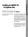
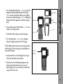
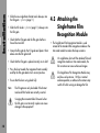
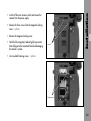
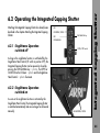
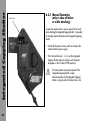
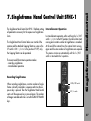
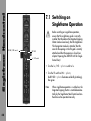
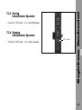
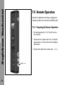
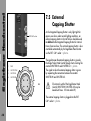
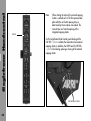
1
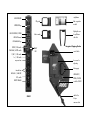
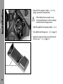
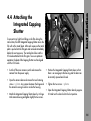
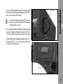
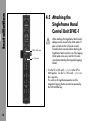
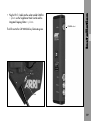
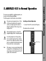
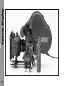
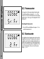
ICS-1 • SFHC-1
Instruction Manual
Integrated Capping Shutter 1 ICS-1
Single Frame Hand Control SFHC-1
As of: June 28th 1999
ALL
THEY MUST NOT
BE COPIED FOR REPRODUCTION (E.G. ON
ARTWORK, PICTURES AND TEXTS ARE COVERED BY OUR COPY-RIGHT.
CD-ROM DISKS OR INTERNET-SITES) OR USED IN THEIR ENTIRE FORM OR IN EXCERPTS WITHOUT OUR PREVIOUS
IF YOU ARE DOWNLOADING PDF-FILES FROM OUR INTERNET HOME-PAGE FOR YOUR PERSONAL USE, MAKE SURE TO CHECK FOR UPDATED VERSIONS.
WE CANNOT TAKE ANY LIABILITY WHATSOEVER
FOR DOWNLOADED FILES, AS TECHNICAL DATA ARE SUBJECT TO CHANGE WITHOUT NOTICE.
WRITTEN AGREEMENT.
singleframe-
LED EXPOSURE
ICS-guide
film recognition
module
EXPOSURE key
light-tight cover
LED CAP CLOSE / OPEN
slide-in mask
LED CAP Manual
for pull-down
claw slits
CAP MANUAL key
SF OFF / ON switch
READY
CAP MAN / AUTO switch
LED
1/SEC / SEC switch
1x / INT switch
exposure time
Integrated Capping Shutter
control knob
hex-screw for
adjusting
locking grip
interval time
HRS:MIN / MIN:SEC
LED READY /
INT. switch
OPEN / CLOSE
BURST FRAMES
socket for SFHC-1
SFHC-1
cable to the
26 pin
camera-socket
1.
Contents
3
2.
Safety Instructions
5
3.
General Description
7
6.
Integrated Capping Shutter
6.1
6.2
7.
Modifying the ARRIFLEX 435
for Singleframe Takes
4.1
4.2
4.3
4.4
4.5
5.
9
General ............................................. 9
Preparing the Film Gate ..................... 10
Attaching the Singleframe Film
Recognition Module ........................... 12
Attaching the Integrated Capping Shutter .. 15
Attaching the Singleframe
Hand Control Unit SFHC-1 ................. 18
ARRIFLEX 435 in Normal Operation
21
7.3
7.4
7.5
7.6
8.
Light-Tightness ................................... 23
Operating the Integrated Capping Shutter .. 25
Singleframe Hand Control Unit SFHC-127
7.1
7.2
4.
23
Contents
1. Contents
Switching on Singleframe Operation ... 28
Recording Singleframes
(Photographic Mode) ......................... 29
Intervallometer Operation ................... 32
Remote Operation ............................. 36
External Capping Shutter .................... 38
Light Control ..................................... 41
Indicators on the Camera Display
8.1
8.2
8.3
8.4
47
Configuring Mode 1
of the Camera Display ....................... 47
Framecounter .................................... 48
Burstcounter ...................................... 48
Interval Time ..................................... 49
3
Contents
4
9.
Trouble-Shooting
51
Camera Warnings ...................................... 55
10.
Technical Data
57
11.
Index
59
12.
ARRI Service
65
Warnings
• Never operate the movement locking mechanism while
the camera is running!
Note:
Operational error possible!
• Ensure that the camera is in a stable position!
Danger of injury or damage to the equipment!
• Remove the battery cable before transporting the camera!
General Safety Instructions
Attention! Danger of injury! Never
reach into the lens mount receptacle,
the interior of the camera or the magazine while the camera is running.
• Remove the battery cable before carrying out maintenance
or cleaning!
• Repairs should only be carried out by authorised
service centers!
• Use only original ARRI spare parts and accessories!
• To ensure safe, proper operation, please familiarise
yourself with this instruction manual.
Important Instructions
• Assembly and initial operation should be carried out
by trained personnel only!
• In wet weather precautions must be taken to protect
electrical equipment.
• Never run the camera without a lens or protective cap
on the lens mount receptacle!
• Avoid operational errors!
Safety Specifications
2. Safety Instructions
• Do not remove any screws which are secured with paint!
5
Safety Specifications
6
Product Specifications
Note on Compliance:
In case of enquiries or when ordering, always state the
model and serial numbers.
This product and the accessories recommended by the
manufacturer comply with the requirements of EUGuideline 89/336/EWG.
Explanation of the Symbols
in this Instruction Manual
➪ photo indicates objects shown in the photographs.
System Overview
The system comprises the following components:
• The Singleframe Hand Control Unit SFHC-1 ➪ photo,
which facilitates setting all important parameters for
singleframe shots.
• The Integrated Capping Shutter (ICS), which ensures that
the camera is light-tight around the mirror shutter for a
period of approx. one hour for taking singleframe shots.
Introduction
3. General Description
• The Singleframe Film Recognition Module ➪ photo,
which is used instead of the standard film recognition
module or the time code module to reduce the curvature
of the film loop.
• The Singleframe Software, which controls all singleframe
functions in the ARRIFLEX 435.
• The Slide-In Mask ➪ photo and the ICS-Guide ➪ photo
to modify the film gate.
• A light-tight cover ➪ photo for the pull-down claw
slits and the register-pin holes in the film gate.
7
Installation
26 pin socket
8
First, check that a 26-pin socket is visible on the right lower
side of the camera, as this is necessary for singleframe takes.
If there is no socket, the camera must be modified by an
authorised ARRI service center.
4.1 General
Due to the design of mirror-reflex film cameras, stray light
may pass around the mirror shutter onto the film when the
camera is not running. For normal film shots this is not a
problem, as the affected images fall into the camera runup, which is usually not used anyway. On singleframe shots
however, the stray light which during interval time can fall
onto the film around the mirror shutter can affect the quality
of the exposed singleframes.
Installation
4. Modifying the ARRIFLEX 435
for Singleframe Takes
The ARRI Integrated Capping Shutter covers the film during
the interval time with a thin metal plate. The metal plate is
pushed into the film gate after exposure. Before the next
exposure the plate is removed.
9
Installation
4.2 Preparing
the Film Gate
format mask
film
gate
locking
lever
knurled knob
filter
holder
movement
locking lever
film gate
To accomodate the movement of the pulldown claw during
film-transport, the film gate is designed with vertical slits
on both sides. Furthermore, there are two holes for the
register-pins. These openings must be covered to prevent
stray light from reaching the film.
To enable the shutter plate of the Integrated Capping Shutter
to slide into the film gate, a special guide is inserted into the
film gate in place of the filter holder. The plate then slides
into this ICS-Guide. Due to the form of the ICS-Guide it is
necessary to use special format masks.
• Before removing the film gate turn off the camera’s main
switch and remove the camera from the power supply.
film gate
shaft
10
• Turn the knurled knob ➪ photo until its marking
matches that on the movement block.
• Turn the movement locking lever ➪ photo to the “OPEN”
position. This will cause the movement block to swing
away from the film gate.
ICS-guide
film gate
ICSformat mask
• Grasp the film gate by the filter holder ➪ photo and
remove it by pulling upwards.
cover
screws
• Pull the filter holder sideways out of the film gate.
Installation
• Press the film gate locking lever ➪ photo towards the
magazine throat assembly and push the film gate ➪
photo towards the movement block, pressing lightly
on the lower end of the film gate ➪ photo and paying
attention that the film gate does not hit the movement
block.
• Press the format mask ➪ photo on its side plate
backwards slightly and pull out of the film gate.
The filter holder and the format mask are held in position
by leaf springs. These leaf springs are each held by two
screws to the film gate.
modified
film gate
• Entirely remove the screws holding the lower single
leaf spring, leaving the spring in place.
• Place the cover for the film gate openings over the
fastening holes of the leaf spring. The cover will
deform slightly. Then screw in the cover and the leaf
spring with the two screws.
11
Installation
• Slide the new singleframe format mask sideways into
the film gate ➪ photo (page 11).
• Slide the ICS-Guide ➪ photo (page 11) sideways into
the film gate.
• Check that the film gate and the film gate shaft are
free of dust and dirt.
• Grasp the film gate by the ICS guide and place it from
above onto the film gate shaft.
• Check that the film gate is placed correctly on its shaft.
• Press the lever towards the magazine throat assembly
and flip the film gate back into its correct position.
• Ensure that the lever swings back fully.
Note:
The film gate can only be locked if the format
mask and filter holder are correctly inserted.
Swinging the movement block forwards when
the film gate is not correctly in place can cause
damage to the equipment!
12
4.3 Attaching the
Singleframe Film
Recognition Module
• The Singleframe Film Recognition Module is used
instead of the standard film recognition module or the
time code module to reduce the loop curvature.
On singleframe shots with the standard film end
recognition module or time code module, the
film curvature can cause unfocused images.
The Singleframe Film Recognition Module may
only be used up to max. 120 fps in normal
camera operation, as otherwise the camera may
switch off while running or damage the film.
• Remove the three screws from the magazine locking
cover ➪ photo.
• Remove the magazine locking cover.
• Hold the film recognition module tightly to prevent it
from falling onto the movement block and damaging
the module’s surface.
screws
Installation
• Switch off the main camera switch and remove the
camera from the power supply.
• Unscrew both fastening screws ➪ photo.
fixing screws
13
Installation
• Remove the film recognition module ➪ photo by
pulling it towards the movement block.
TC- or film recognition
module
When attaching the new module, ensure
correct plug positioning as otherwise damage
could be caused to the plug contacts!
• Attach the singleframe film recognition module ➪ photo.
• Screw tight the two fastening screws ➪ photo (page 13).
• Replace the magazine locking cover and fasten with
the three screws ➪ photo (page 13).
singleframe film recognition module
14
screws
To prevent stray light from falling on the film during the
interval time, the ARRI Integrated Capping Shutter covers the
film with a thin metal plate. After each exposure the metal
plate is pushed into the film gate and removed immediately
before the next exposure. The metal plate slides into the
ICS-Guide attached to the film gate. To ensure optimum
operation, the plate of the Capping Shutter must be aligned
with the ICS-Guide.
• Switch off the main camera switch and remove the
camera from the power supply.
• Open the camera door and remove the two fastening
screws ➪ photo. Any spacers between the hinge and
the camera housing should on inside the housing.
• Attach the Integrated Capping Shutter door by its hinge
to the camera housing and tighten slightly the two screws.
Installation
4.4 Attaching the
Integrated Capping
Shutter
• Position the Integrated Capping Shutter door so that
there is an even gap to the housing and the door can
be correctly opened and closed.
• Tighten the two screws ➪ photo.
• Open the Integrated Capping Shutter door by approx.
30° and turn the door lock to the shut position.
15
Installation
• Press the control knob ➪ photo on the Integrated
Capping Shutter and turn until the black plate reaches
the ICS-Guide.
Note:
control knob
shutter plate
If the knob cannot be turned check if the door
lock is really in the shut position.
Do not use force to push the plate into the ICSGuide, as this could damage the plate or the guide.
ICS-guide
hex screw
for
height adjustment
• Check that the plate can be pushed into the ICS-Guide
easily and without catching. The height of the plate can
be set on the side of the ICS with the hex key ➪ photo.
Note:
If the height of the plate is correctly set but it still
catches when being pushed in, the positioning
of the entire ICS door on the camera should be
re-checked.
• Check again that the plate slides into the ICS-Guide
easily and without catching.
16
door locked
To prevent inadvertent opening of the camera
door, it can only be opened when the Integrated
Capping Shutter is open.
• Press the control knob of the Integrated Capping Shutter
and turn. The plate will be pushed slowly into the ICSGuide. Pay attention to proper and smooth operation.
Installation
• Press the control knob of the Integrated Capping Shutter
and turn it until the black plate disappears in the ICS
door. Close and lock the ICS door.
• Plug the cable of the Integrated Capping Shutter into
the 26-pin socket ➪ photo on the lower right side of
the camera and screw tight.
26 pin socket
17
Installation
4.5 Attaching the
Singleframe Hand
Control Unit SFHC-1
SF ON / OFF switch
1x / INT switch
When attaching the Singleframe Hand Control,
damage can be caused to the shutter plate if it
does not slide into the ICS-Guide correctly.
Therefore check manually before attaching the
Singleframe Hand Control to see if the Capping
Shutter plate slides easily into the ICS-Guide
(see chapter Attaching the Integrated Capping
Shutter).
• Turn the SF or CAP switch ➪ photo to the OFF or
MAN position. Turn the 1x / INT switch ➪ photo to
the 1x position.
This switches off singleframe operation and the
Integrated Capping Shutter can later be operated by
the CAP-MANUAL key.
18
The LED next to the CAP-MANUAL key illuminates green.
CAMERA socket
Installation
• Plug the SF-C1-S cable into the socket marked CAMERA
➪ photo on the Singleframe Hand Control and the
Integrated Capping Shutter ➪ photo.
socket
19
20
The camera, once modified for singleframe operation, can
be used normally with some restrictions.
The following points should be taken into consideration:
The camera may be operated at max. 120 fps
with the special singleframe film recognition
module, as at higher speeds the camera is in
danger of switching off while running or may
damage the film.
Switching on Normal Operation
• Turn the SF ON/OFF switch to the OFF position.
The camera can be used normally.
Before starting the camera run, check if the
Integrated Capping Shutter is completely opened.
Due to the light-tight cover for the pull-down
claw slits and the register-pin holes in the film
gate, dirt or film snippets may collect in the film
gate. It must therefore be checked and cleaned
far more often than in normal operation.
Note:
Normal Operation
5. ARRIFLEX 435 in Normal Operation
SF ON / OFF switch
If the camera is running in normal mode and the
Capping Shutter is not completely open, the entire
camera display or the RCU-display and the ASY
symbol in the viewfinder blink.
21
22
6.1 Light-Tightness
Due to the design of mirror-reflex film cameras, stray light
may pass around the mirror shutter onto the film when the
camera is not running. For normal film shots this is not a
problem, as the affected images fall into the camera runup, which is usually not used anyway. On singleframe shots
however, the stray light, which can fall onto the film around
the mirror shutter during interval time, can affect the quality
of the exposed singleframes.
The maximum interval time which can pass between exposing
two singleframes without the images being affected is referred to as the light-tightness of the camera. The lighttightness on normal mirror reflex cameras is very short due
to the general construction. On the standard ARRIFLEX 435
this interval can be less than one second under disadvantageous circumstances.
To prevent light from falling onto the film during the interval
time, so-called capping shutters are used. These capping
shutters are usually leaf shutters which are mounted in front
of the camera lens. As long as the leaf shutters are closed,
no light can reach the lens or the film. The capping shutter
is opened just before exposure of the singleframe and then
closed again. A disadvantage of this type of capping shutter
is that there is no way to evaluate the image through the
viewfinder – the lens and therefore also the viewfinder
remain light-tight.
The Integrated Capping Shutter on the other hand, blocks
the light behind the mirror, i.e. directly in front of the film
gate. Thus, viewing the image through the viewfinder is
always possible. However, since light is admitted into the
camera-body, even with the Integrated Capping Shutter the
camera is only light-tight for approx. one hour under
normal lighting conditions. For interval times of over an
hour, an external capping shutter should be used in front
of the lens in addition to the Integrated Capping Shutter
(see chapter External Capping Shutter).
It is also necessary to close the eyepiece of the viewfinder
to prevent light form leaking through the viewfinder into
the camera.
Integrated Capping Shutter
6. Integrated Capping Shutter
23
Integrated Capping Shutter
24
The following five important rules result:
Never shoot singleframe shots without the
Integrated Capping Shutter.
During interval times of over an hour use an
external Capping Shutter in addition to the
Integrated Capping Shutter.
To ensure that the light-tightness of the camera
is sufficient, check for light-tightness under the
same conditions as the intended shots.
During interval times of over a few seconds, the
camera or magazines parts which do not need
to be accessible should be covered with a black
cloth or similar.
Allways close the eypiece after checking the
viewfinder before filming single frames.
Attaching the Integrated Capping Shutter has already been
described in the chapter Attaching the Integrated Capping
Shutter.
LED
CAP OPEN / CLOSE
LED
CAP-MANUAL key
CAP-MANUAL
6.2.1 Singleframe Operation
switched off
SF ON / OFF switch
As long as the singleframe function is switched off by the
Singleframe Hand Control (SF switch in position OFF), the
Integrated Capping Shutter can be opened or closed by
pressing the CAP-MANUAL key ➪ photo. The OPEN or
CLOSE LED on the ICS door ➪ photo and the Singleframe
Hand Control ➪ photo illuminate.
6.2.2 Singleframe Operation
switched on
As soon as the singleframe function is activated by the
Singleframe Hand Control, the Integrated Capping Shutter
is controlled automatically and can no longer be influenced
manually.
Integrated Capping Shutter
6.2 Operating the Integrated Capping Shutter
LED CAP OPEN / CLOSE
25
Integrated Capping Shutter
26
control knob
6.2.3 Manual Operation
(only in case of failure
or while attaching)
To open the camera door in case or power failure, and
when attaching the Integrated Capping Shutter, it is possible
to manually operate the plate on the Integrated Capping
Shutter.
• Switch off the camera’s main switch and remove the
camera from the power supply.
• Press the control knob ➪ photo on the Integrated
Capping Shutter and turn clockwise until the plate
disappears in the ICS door (OPEN position).
The camera door can only be opened if the
Integrated Capping Shutter is open.
Manual operation of the Integrated Capping
Shutter is only possible if the door lock is shut.
The Singleframe Hand Control Unit SFHC-1 facilitates setting
all parameters necessary for the exposure of singleframe
shots.
The Singleframe Hand Control takes over control of the
camera and the attached Capping Shutter as soon as the
SF switch is ON ➪ photo. In the position SF OFF, only
the Capping Shutter can be operated.
Intervallometer Operation
In intervallometer operation, after switching the 1x / INT
switch ➪ photo to the INT position, the interval time starts
running and a certain number of singleframes is recorded.
At the end of the interval time, the interval starts running
again and the same number of singleframes are exposed.
This process carries on automatically until the 1x / INT
switch is returned to the 1x position.
There are two different main operation modes:
- recording singleframes
- intervallometer operation
Recording Singleframes
When recording singleframes, a certain number of singleframes is directly recorded in sequence each time the exposure key is pressed. Then the Singleframe Hand Control
waits until the exposure key is pressed again. The number
of images recorded each time is set with the BURST FRAMES
keys.
SF ON / OFF switch
INT / 1x switch
Singleframe Handcontrol
7. Singleframe Hand Control Unit SFHC-1
27
Singleframe Handcontrol
28
7.1 Switching on
Singleframe Operation
SF ON / OFF switch
Before switching on singleframe operation,
ensure that the singleframe guide is correctly
installed, that the plate on the Integrated Capping
Shutter can be moved easily, that the Singleframe
Film Recognition module is attached, that the
cover for the openings in the film gate is correctly
attached and that the eyepiece is closed (see
chapter Preparing the ARRIFLEX 435 for Singleframe Shots).
RDY LED
1x / INT switch
• Turn the 1x / INT ➪ photo switch to 1x.
• Turn the SF switch to ON ➪ photo;
the RDY LED ➪ photo illuminates red briefly (initialising),
then green.
Note:
When singleframe operation is switched on, the
Integrated Capping Shutter is controlled automatically by the Singleframe Hand Control and can
therefore not be operated manually.
EXPOSURE key
When recording singleframes, a certain number of singleframes is recorded directly in sequence each time the exposure key is pressed. Then the Singleframe Hand Control
waits until the exposure key is pressed again.
• The 1x / INT switch ➪ photo must be at the 1x position.
1x / INT switch
7.2.1 Setting the Repeat Counter (burst)
The repeat counter ➪ photo sets the number of singleframes
which will be recorded each time the exposure key ➪ photo
is pressed.
exposure time
• Set the desired number with the BURST FRAME keys
➪ photo.
On the repeat counter, values from 0 to 99 frames can be set.
Note:
BURST FRAMES
Singleframe Handcontrol
7.2 Recording Singleframes
(Photographic Mode)
If the repeat counter is set to 0, one frame will
still be recorded when the exposure key is pressed.
29
Singleframe Handcontrol
30
7.2.2 Setting the Exposure Time
EXPOSURE key
1/SEC SEC switch
exposure time
1x / INT switch
The shortest exposure time with a camera shutter angle of
180° is 1/8 second. All shorter exposure times are set by
adjusting the angle of the mirror shutter on the camera.
The ARRIFLEX 435ES is equipped with an electronically
adjustable mirror shutter. This enables the shutter angle to
be automatically adjusted for shorter exposure times by
the Singleframe Hand Control. On the Singleframe Hand
Control various exposure times can be set:
exposure times from 1/128s to 999s with an ARRIFLEX 435ES,
and exposure times of 1/8s to 999s when using an
ARRIFLEX 435.
If exposure times of under 1/8 s are required on an
ARRIFLEX 435, the shutter angle must be manually adjusted
beforehand (see Instruction Manual ARRIFLEX 435).
Note:
BURST FRAMES
On longer exposure times – over approx. one
second – the reciprocity behaviour of the film
becomes visible. This means that the film’s colour
reproduction changes. Further information is
available from the film manufacturers.
7.2.3 Recording Singleframes
• Press the exposure key ➪ photo.
• With the 1/SEC SEC switch ➪ photo, select if the
exposure time is displayed as whole seconds or as
fractions of a second.
For cameras with an electronically adjustable
mirror shutter the shutter angle is adjusted by
the Singleframe Hand Control. Prior settings
will be overwritten.
After pressing the exposure key the Integrated Capping
Shutter opens. Then the number of singleframes set on the
BURST FRAMES switch will be recorded with the set exposure time. After the last singleframe the Integrated
Capping Shutter closes again.
• For further singleframes press the exposure key again.
Note:
For recording singleframes a matching interval
time must also be set.
Singleframe Handcontrol
• Set the desired exposure time with the EXPOSURE
TIME keys ➪ photo.
31
Singleframe Handcontrol
7.3 Intervalometer
Operation
EXPOSURE key
1/SEC SEC switch
1x / INT switch
The interval time is defined as follows: it extends from the
opening of the Integrated Capping Shutter for the first singleframe of a singleframe cycle to the opening of the Integrated
Capping Shutter for the first singleframe of the next singleframe cycle.
exposure time
Interval Time
HRS:MIN / MIN:SEC
BURST FRAMES
For intervalometer operation the 1x / INT switch ➪ photo
is set to the INT position. The interval time begins running,
the integrated capping shutter opens and a certain number
of singleframes is recorded. After the set interval time has
ended the process is repeated and the same number of
singleframes is recorded. This operational mode is completely automatic and continues until the 1x / INT switch
is returned to the 1x position.
switch
7.3.1 Setting the Repeat Counter (burst)
The repeat counter sets the number of singleframes to be
recorded in a cycle.
• Set the desired number with the BURST FRAMES switches.
32
Note:
If the repeat counter is set to 0, one frame will still
be recorded when the exposure key is pressed.
7.3.2 Setting the Exposure Time
The shortest exposure time with a camera shutter angle of
180° is 1/8 second. All shorter exposure times are set by
adjusting the angle of the mirror shutter on the camera.
The ARRIFLEX 435ES is equipped with an electronically adjustable mirror shutter. This enables automatic adjustment
of the shutter angle for shorter exposure times by the
Singleframe Hand Control. On the Singleframe Hand
Control various exposure times can be set:
Exposure times from 1/128s to 999s with an ARRIFLEX 435ES,
and exposure times from 1/8s to 999s when using an
ARRIFLEX 435.
If exposure times shorter than 1/8s are required of an
ARRIFLEX 435, the shutter angle must be manually adjusted
beforehand (see Instruction Manual ARRIFLEX 435).
Note:
On longer exposure times – over approx. one
second – the reciprocity behaviour of the film
becomes visible. This means that the colour reproduction of the film changes. Further information
is available from the film manufacturers.
• Set the desired exposure time with the EXPOSURE
TIME keys ➪ photo.
• With the 1/SEC SEC ➪ photo switch, select if the
exposure time is displayed as whole seconds or as
fractions of a second.
7.3.3 Setting the Interval Time
• Set the desired exposure time with the INTERVAL TIME
keys ➪ photo.
• With the HRS:MIN / MIN:SEC switch ➪ photo, select
if the interval time is shown as hours:minutes or
minutes:seconds.
Singleframe Handcontrol
Values from 0 to 99 frames can be set on the repeat counter.
33
Singleframe Handcontrol
34
Note:
The interval time is defined as follows: it reaches
from the opening of the Integrated Capping
Shutter for the first singleframe of a singleframe
cycle to the opening of the Integrated Capping
Shutter for the first singleframe of the next
singleframe cycle.
7.3.4 Minimum Interval Time
The minimum interval time is calculated from the exposure
time and the number of repeats (burst). It can be calculated
as follows:
On the Singleframe Hand Control, the next higher interval
time can be set (e.g. calculated minimum interval time:
1.12s => interval time set: 2s).
The offset is created by the time the movement mechanism
needs to transport the film after the mirror shutter is closed.
The offset and two samples can be determined in the
following table:
Exposure time
Offset
e.g.: burst=1
e.g.: burst=2
min. interval time min. interval time
999s – 1/2s
0.58s
Minimum interval time = (exposure time+offset)*burst + 0.4s
1/3s
0.39s
1.12s => 2s
1.85s => 2s
The 0.4 seconds at the end of the formula represent the time
the Integrated Capping Shutter needs to open and close.
1/4s
0.3s
0.95s => 1s
1.50s => 2s
Note:
SFHC with software versions before SFHC 2.11
use 0.6 seconds.
1/5s
0.23s
0.83s => 1s
1.26s => 2s
1/6s
0.2s
0.87s => 1s
1.13s => 2s
Note:
For exposure times under 1/8s, 1/8s is still
used in the formula, as exposure times under
1/8s are achieved through the shutter angle.
1/7s
0.16s
0.70s => 1s
1.01s => 2s
1/8s – 1/128s
0.14s
0.67s => 1s
0.93s => 1s
• Turn the 1x / INT switch ➪ photo to the INT position.
7.3.6 Stopping
Intervallometer Operation
• Turn the 1x / INT switch ➪ photo to the 1x position.
INT / 1x switch
Singleframe Handcontrol
7.3.5 Starting
Intervallometer Operation
35
Singleframe Handcontrol
36
7.4 Remote Operation
Activation of singleframes and starting or stopping intervallometer operation can be remotely controlled by cable.
7.4.1 Preparing for Remote Operation
• For remote operation the 1x / INT switch must be in
the 1x position.
• Set exposure time, repeat counter and – for intervallometer operation – the interval time on the Singleframe
Hand Control.
• Plug the remote cable into the remote socket ➪ photo.
REMOTE socket
• Through brief connection (minimum 0.05s) of the
TRIGGER 1x and GND contacts, a singleframe cycle is
started (as if pressing the exposure key).
1
GND
2
TRIGGER-1X
3
7.4.3 Starting Intervallometer
Operation
• By connecting the TRIGGER INT and GND contacts,
intervallometer operation is started. This runs as long
as the contacts remain connected.
TRIGGER-INT
1
2
X4
3
Singleframe Handcontrol
7.4.2 Activating Singleframes
37
Singleframe Handcontrol
7.5 External
Capping Shutter
As the Integrated Capping Shutter is only light-tight for
approx. one hour under normal lighting conditions, an
external capping shutter in front of the lens should be used
in addition to the Integrated Capping Shutter for interval
times of over an hour. The external capping shutter is also
controlled automatically by the Singleframe Hand Control
via the EXT. CAP. socket ➪ photo.
EXT. CAP. socket
1
GND
2
SHUTTER TIME
3
SHUTTER-HI
4
SHUTTER-LO
The signal to open the external capping shutter is given by
the Single Frame Hand Control through short-circuiting the
contacts SHUTTER-HI and SHUTTER-LO ➪ photo.
The signal to close the external capping shutter is given
by separating the connection between the contacts
SHUTTER-HI and SHUTTER-LO.
1
4
2
3
X3
The internal switch of the Singleframe Hand
Control (SHUTTER-HI, SHUTTER-LO) may be
loaded with max. 100 mA and 60V).
The external capping shutter is plugged into the EXT.
CAP. socket ➪ photo.
38
Resistance [ohm] .................................... Time [s]
100 .................................................................. 0.1
150 .................................................................. 0.2
200 .................................................................. 0.3
270 .................................................................. 0.4
360 .................................................................. 0.5
470 .................................................................. 0.7
Select the resistance to ensure that the capping
shutter is completely opened before exposure
begins.
620 .................................................................. 1.0
820 .................................................................. 1.4
1200 ................................................................ 2.0
2000 ................................................................ 3.1
The following table shows resistance values and the resulting times. If the contacts are only short-circuited, a time
of 2.5 seconds results.
2700 ................................................................ 4.1
3600 ................................................................ 5.0
4700 ................................................................ 6.2
5600 ................................................................ 6.9
6800 ................................................................ 7.9
10000 .............................................................. 9.7
Cables are available upon request.
Singleframe Handcontrol
External capping shutters need more time to open than the
Integrated Capping Shutter. The length of time to open the
external capping shutter in advance is determined by a
resistance between the contacts SHUTTER-TIME and GND in
the cable. Combined with this resistance, the Singleframe
Hand Control gives the signal to open the external capping
shutter in time.
39
Singleframe Handcontrol
Note:
CAP LED
When starting the interval, the external capping
shutter is switched on first. The first exposure takes
place after the set shutter opening time, as
determined by the resistance, has ended. The
interval time runs from the opening of the
integrated capping shutter.
On the Singleframe Hand Control green blinking of the
CAP LED ➪ photo indicates the connection of an external
capping shutter. In addition, the OPEN and CLOSE LEDs
➪ photo blink during opening or closing of the external
capping shutter.
LED CAP OPEN / CLOSE
40
7.6.1 Switching on/off Light
LIGHT socket
The Singleframe Hand Control generates output signals
which enable through the LIGHT socket ➪ photo luminaires
to be switched on via an external power circuit at a certain
time before exposure and then switched off immediately
after exposure. The signal to activate the light is given by
the Singleframe Hand Control by short-circuiting the
contacts LIGHT-HI and LIGHT-LO ➪ photo.
How long before exposure the signal for the light is given
can be determined via a resistance between the contacts
LIGHT-TIME and GND ➪ photo in the cable which is
plugged into the LIGHT socket.
Select the resistance so that all lighting instruments
reach their full brightness and colour temperature.
The internal switch of the Singleframe Hand
Control (LIGHT-HI, LIGHT-LO) may be loaded
with max. 100 mA and 60V).
1
GND
2
LTM –>SF
3
SF –> LTM
4
LIGHTMETER
5
GND
6
5V-LTM
7
LIGHT-TIME
8
GND
9
LIGHT-HI
10
LIGHT-LO
11
FLASH-HI
12
FLASH-LO
4
5
6
1
12
3
2
7
8
11
10
9
X2
Singleframe Handcontrol
7.6 Light Control
41
Singleframe Handcontrol
42
Resistance [ohm] .................................... Time [s]
100 .................................................................. 0.1
The following table shows the resistance values and the
resulting times. If the contacts are only short-circuited, the
time will be 5.3 seconds
150 .................................................................. 0.2
200 .................................................................. 0.3
Note:
When starting the interval, the light is switched
on first, and the first exposure takes place after
the time determined by the resistance. The
interval time runs from the opening of the
integrated capping shutter.
Note:
The light control is active for interval times longer
than 20 seconds. For Interval times shorter than
this, the contacts remain closed.
270 .................................................................. 0.4
360 .................................................................. 0.5
470 .................................................................. 0.7
620 .................................................................. 1.0
820 .................................................................. 1.4
1200 ................................................................ 2.0
2000 ................................................................ 3.1
2700 ................................................................ 4.1
3600 ................................................................ 5.0
4700 ................................................................ 6.2
5600 ................................................................ 6.9
6800 ................................................................ 7.9
10000 .............................................................. 9.7
Cables are available upon request.
The Singleframe Hand Control generates an output signal
to control a flash. Commercially available flash units can
be used. They are plugged into the LIGHT socket ➪ photo
with a special cable. The signal to activate the flash is given
by the Singleframe Hand Control by short-circuiting the
contacts FLASH-HI and FLASH-LO ➪ photo.
LIGHT socket
When selecting a flash unit make sure that it recharges quickly enough. The Singleframe Hand
Control does not check whether the flash is ready
for use.
When exposing with flash, the entire image is
exposed at once. The shutter angle of the camera
may therefore not be smaller than 45°.
A minimum exposure time of 1/32s results.
The internal switch of the Singleframe Hand
Control (FLASH-HI, FLASH-LO) may be loaded
with max. 100 mA and 60V).
1
GND
2
LTM –>SF
3
SF –> LTM
4
LIGHTMETER
5
GND
6
5V-LTM
7
LIGHT-TIME
8
GND
9
LIGHT-HI
10
LIGHT-LO
11
FLASH-HI
12
FLASH-LO
4
5
6
1
12
3
2
7
8
11
10
9
X2
Singleframe Handcontrol
7.6.2 Flash Control
43
Singleframe Handcontrol
44
7.6.3 Exposure Meter
An exposure meter can be plugged into the Singleframe
Hand Control LIGHT socket via a special cable. The exposure
time is then adapted automatically to the changing light
conditions. This function can be used with intervallometer or
singleframe operation.
LIGHT socket
1
GND
2
LTM –>SF
3
SF –> LTM
4
LIGHTMETER
5
GND
6
5V-LTM
7
LIGHT-TIME
8
GND
9
LIGHT-HI
10
LIGHT-LO
11
FLASH-HI
12
FLASH-LO
The power supply of the exposure meter can take place
via the contact 5V-LTM ➪ photo at +5V max. 100mA.
The exposure meter signal is scanned in via the contact
LIGHTMETER ➪ photo. The voltage range is between 0
and 5V. An increase in voltage of +0.05V is equivalent to
halving the light measured. A voltage reduction of 0.05V
is equivalent to doubling the light.
• Set the repeat counter (and if necessary the interval time)
on the Singleframe Hand Control.
4
5
6
1
12
3
2
7
8
11
10
X2
• Attach the exposure meter with the special cable to the
Singleframe Hand Control LIGHT socket.
9
• Adjust the exposure meter so that it correctly measures
the light of the scene to be recorded.
• Set the exposure time on the Singleframe Hand Control
for the current lighting conditions.
The Singleframe Hand Control adapts the exposure time
to changing lighting conditions immediately before the
next exposure.
Note:
By switching the singleframe operation off and
on (SF switch OFF / ON) the current lightmeter
values are erased.
time will be exceeded. The next exposure then
begins immediately after the last one has ended.
(For precise calculation of the minimum interval
time see the heading Minimum Interval Time)
Note:
On longer exposure times (over approx. one
second), the reciprocity behaviour of the film
becomes visible. This means that the film’s colour
reproduction changes. Further information is
available from film themanufacturers.
For ASAHI Pentax Spotmeter V with integrated interface
(Norris) the cable SF-L1-S is available K2.52069.0.
When setting exposure time particular attention
must be paid to the way in which the lighting
conditions will probably change so that exposure
time limits are not exceeded.
Note:
If the exposure time drops under its limits during
filming, the takes continue with the shortest
possible exposure time. The READY LED on the
Singleframe Hand Control blinks red.
Note:
If the exposure time multiplied by the number of
repeats (burst) exceeds the set interval time due to
changing lighting conditions, exposure time will
continue with the current values, i.e. the interval
INT / 1x switch
Singleframe Handcontrol
• With the first exposure (pressing the exposure key or
starting the intervallometer operation by switching the
1x / INT switch to INT ➪ photo) the lightmeter operation
is started (RDY LED blinks green).
45
Camera Display
MODE key
46
SET key
SEL key
As soon as singleframe operation on the Singleframe
Hand Control is switched on (switch SF to ON), “SF” is
displayed in the lower line of the camera display.
8.1 Configuring Mode 1
of the Camera Display
In Mode 1 of the camera display (recognisable by the
horizontal black bar in the upper right-hand corner)
various information can be displayed. The following four
indications can be set:
• If the display is not in Mode 1 (recognisable by the
horizontal black bar in the upper right-hand corner),
change to Mode 1 by pressing the MODE key ➪ photo
several times.
• Total exposed film or take counter in meters or feet
depending on the setting (see Instruction Manual
ARRIFLEX 435), recognisable by the m/ft symbol in
the display.
• Press the SEL key ➪ photo several times to select the
desired indications.
Camera Display
8. Indicators on the Camera Display
• Press the SET key ➪ photo to confirm the selection.
• Shutter angle of the mirror shutter, recognisable by the
triangular symbol in the display.
• Framecounter, recognisable by the letters Fr in the lower
display line.
• Remaining interval time, recognisable by the colon
between hours and minutes in the upper display line.
47
Camera Display
8.2 Framecounter
In the upper line of the camera display the total number
of recorded singleframes is displayed ➪ photo. If the
camera runs in reverse, the framecounter can also display
negative values. A minus-sign is then displayed in front of
the letters FR.
Resetting the Framecounter
• Press the SET key and hold down for approx. 1.5 s to
reset the framecounter to 0.
8.3 Burstcounter
On singleframe shots the repeat counter can be set on the
Singleframe Hand Control. This determines the number of
singleframes which will be recorded immediately after one
another in each singleframe cycle. When starting the singleframe cycle, the remaining number of singleframes in this
cycle will be displayed in the lower line of the camera
display ➪ photo.
48
In Mode 1 of the camera display the remaining interval
time can be displayed.
In the upper line the remaining hours and minutes are displayed, in the lower line next to the letters SF the remaining
seconds ➪ photo.
If the interval has not yet started, in the upper line intermittent
dashes will be displayed and in the lower line “SF:INT”.
Camera Display
8.4 Interval Time
49
50
Display
Display
Cause
Remedy
RDY LED does not illuminate
CAP-MANUAL illuminates red
Integrated Capping Shutter fault
• Shut camera door
Camera not ready
• Press CAP-Manual key
(e.g. movement mechanism open)
• Manually check Integrated Capping Shutter
movement and accessibility of end stops
CAP-MANUAL blinks red
Error with external Capping Shutter
• Check external capping shutter
and extension cable
All LEDs blink
Singleframe EPROM in the camera
missing (camera not modified
• Have camera modified by an
ARRI service center
Trouble-Shooting
9. Trouble-Shooting
for singleframe)
RDY LED blinks red
1) Exposure time set outside
acceptable range or 0 seconds
1) Set camera without electronically
adjustable mirror shutter to 1/8s to 999s
Set camera with electronically adjustable
mirror shutter to 1/128s to 999s
51
Trouble-Shooting
Display
Display
RDY LED blinks red
Cause
Remedy
2) Interval time outside
2) If MIN:SEC selected:
acceptable range
set seconds between 0 and 59.
If HRS:MIN selected,
set minutes between 0 and 59.
Calculation of the minimum interval time
see chapter 7.3.4
3) Exposure time with its repeats is
longer than the interval time
Camera not ready
RDY LED illuminates red
3) Increase interval time or reduce
number of repeats or shorten exposure time.
• Swing in movement mechanism.
• Check camera.
• Switch on/off.
• Switch SF switch on/off.
• Replace SF-C1 cable.
RDY LED illuminates red
CAP-MANUAL illuminates red
Error with Integrated Capping Shutter
• Shut camera door
• Switch off SF ON/OFF switch,
• check Integrated Capping Shutter
movement and accessibility of end stops,
• switch on SF ON/OFF switch
52
Display
Cause
RDY LED illuminates red
CAP-MANUAL blinks red
Error with external capping shutter
Remedy
• Switch off SF ON/OFF switch,
• check external capping shutter
and its cable,
• switch on SF ON/OFF switch.
RDY LED blinks red
Exposure LED blinks green
error during interval
1) Set values were altered
1) Reset original settings
during a running interval.
The take is continued with the
original values.
2) With attached,
2) Restart the interval
exposure meter the
if necessary with altered
exposure limits
exposure values
Trouble-Shooting
Display
were exceeded.
Exposure continues
with the min. or max.
possible exposure time
RDY LED illuminates red
Exposure LED illuminates green
Error during exposure.
Possible causes:
1) Camera not ready
1) Check camera
2) CAP-MANUAL LED illuminates red:
2) Check Integrated Capping Shutter move-
Integrated Capping Shutter not ready
ment and accessibility of end stops.
53
Trouble-Shooting
Display
Display
Cause
Remedy
RDY LED illuminates red
Exposure LED illuminates green
3) CAP-MANUAL LED blinks red:
3) Check external capping shutter
error with external capping shutter
RDY LED illuminates red
Exposure LED blinks green
(cable)
4) Filmend
4) Load new film
5) electronic mirror shutter locked
5) Unlock mirror shutter
Error during interval time,
possible causes:
1) Camera not ready
1) Check camera
2) CAP-MANUAL LED illuminates red:
2) Check Integrated Capping Shutter move
Integrated Capping Shutter not ready
3) CAP-MANUAL LED blinks red:
error with external capping shutter
4) Electronic mirror shutter locked
ment and accessibility of end stops
3) check external capping shutter
(cable)
4) Unlock electronic mirror shutter.
5) Camera ASY
RDY LED blinks red/green
Camera power supply too low
• Attach fully charged battery
to the camera
54
Entire camera display or RCU display blinks and ASY symbol in viewfinder blinks
Camera is running in normal mode
and the Capping Shutter
is not completely open
Trouble-Shooting
Camera Warnings
55
56
Integrated Capping Shutter
Settings: ................................... exposure time from 1/8s to 999s
at a mirror shutter angle of 180°.
Temparature Range: .................. -20°C … 50°C
With a mirror shutter angle of 11,2°
Weight: .................................... 540g
the shortes exposure time is 1/128s
Time for opening or closing the Integarted Capping Shutter < 250 ms
Intervallometer operation with interval times
from 1s to 9999s
Singleframe Handcontrol
Temparature Range: .................. -20°C … 50°C
Weight: .................................... 380g
Technical Data
10. Technical Data
burst frames counter 1 to 99
Interfaces: ................................. Signal out for external Capping Shutters
Trigger-input
automatic signal for switching on luminaires
Dimensions: .............................. 55x32x220 mm
intervallometer operation
signal-output for controling a flash
Input for external lightmeter to adapt the
exposure to the actual lighting conditions
57
58
Technical Data
Symbole26-pin socket ............................................ 9
A
ARRI Service ....................................................... 65
ARRIFLEX 435 in Normal Operation ...................... 21
ASAHI Pentax Spotmeter V ................................... 45
ASY Symbol
blinking ........................................................ 21
B
BURST FRAMES ................................................... 31
Setting .......................................................... 32
BURST FRAMES Counter ....................................... 29
Burstcounter ........................................................ 48
C
Cable .......................................................... 36, 39
Cable SF-C1-S ..................................................... 19
Camera Display
Configuring ................................................... 47
Indicators ...................................................... 47
Catching
the ICS .......................................................... 16
Cleaning
the Film Gate ................................................. 21
Colour Reproduction ............................................ 45
Compliance .......................................................... 6
Control Knob ...................................................... 16
Cover
for Film Gate ................................................. 11
Index
11. Index
D
Description, General .............................................. 7
Dimensions ......................................................... 57
Dirt
in Film Gate .................................................. 21
Display
Burstcounter ................................................... 48
Exposed Film ................................................. 47
FR ................................................................ 47
Interval Time .................................................. 49
of Exposure Time ............................................ 31
Shutter Angle ................................................. 47
59
Index
E
Exposed Film Display ........................................... 47
Exposure Meter ................................................... 44
Exposure Time
Setting ................................................... 30, 33
Shortest .................................................. 30, 33
External Capping Shutte ....................................... 23
External Capping Shutter ...................................... 38
F
Film Gate
Cover ........................................................... 11
Modifying ..................................................... 10
Preparing ...................................................... 10
Film Gate Shaft ................................................... 12
Film Recognition Module
Singleframe ................................................... 12
Standard ....................................................... 12
Time Code .................................................... 12
Filming Speed
Maximum with Integrated Capping Shutter . 12, 21
Filter Holder ................................................. 10, 11
Flash Control ....................................................... 43
Format Mask ....................................................... 11
Singleframe ................................................... 12
Format Masks ...................................................... 10
Fractions of a Second .................................... 31, 33
60
Framecounter ...................................................... 48
Resetting ....................................................... 48
H
Height Adjustment of the ICS ................................. 16
I
ICS ...................................................................... 7
ICS-Guide ................................................ 7, 10, 12
Installation ............................................................ 9
Integrated Capping Shutter ................................... 23
Attaching ...................................................... 15
Door ............................................................. 15
Manual Operation ......................................... 26
Operating ..................................................... 25
Positioning the ICS door .................................. 15
Interfaces ............................................................ 57
Interval Time ....................................................... 49
Display ......................................................... 33
Minimum ....................................................... 34
Setting .......................................................... 33
Intervallometer
Operation ..................................................... 32
Intervallometer Operation ..................................... 27
Starting ......................................................... 35
Starting Remote .............................................. 37
Stopping ....................................................... 35
BURST FRAMES ............................................. 29
CAP-MANUAL ............................................... 18
EXPOSURE .................................................... 31
EXPOSURE TIME ..................................... 31, 33
INTERVAL TIME .............................................. 33
Knob, Control ..................................................... 16
L
Leaf Springs ........................................................ 11
LED
CAP ............................................................. 40
CAP-MANUAL ............................................... 19
CLOSE .......................................................... 40
OPEN ........................................................... 40
Light
Switching off ................................................. 41
Switching on ................................................. 41
Light Control ....................................................... 41
Light-Tightness ..................................................... 23
Lighting Conditions
changing ...................................................... 45
Loading
max. for Switching .................................. 41, 43
M
Manual Operation
of the ICS ...................................................... 26
Mode 1 .............................................................. 47
Configuring ................................................... 47
Modifying the ARRIFLEX 435 ................................... 9
Index
K
Key
N
Normal Operation ............................................... 21
Switching On................................................. 21
Norris ................................................................ 45
Note .................................................................... 5
Number of Singleframes ....................................... 29
P
Pentax Spotmeter V .............................................. 45
Photographic Mode ............................................. 29
Product Specifications ............................................ 6
61
Index
R
RCU-Display
blinking ........................................................ 21
Reciprocity Behaviour ........................................... 45
Recording Singleframes ........................................ 27
Remote
Activating Singleframe Recordings ................... 37
Starting Intervallometer Operation .................... 37
Remote Operation ............................................... 36
Remote Socket ..................................................... 36
Repeat Counter ................................................... 29
Setting .......................................................... 32
Resistance-Table ............................................ 39, 42
S
Safety Instructions .................................................. 5
Screws
secured with paint ............................................ 5
Second
Fractions of ................................................... 31
full ................................................................ 31
Seconds ............................................................. 33
Service ............................................................... 65
Settings .............................................................. 57
SFHC-1 ......................................................... 7, 27
Shaft
Film Gate ...................................................... 12
62
Shutter Angle ...................................................... 30
Shutter Angle Display ........................................... 47
Singleframe Film Recognition Module ....................... 7
Attaching ...................................................... 12
Singleframe Hand Control Unit .............................. 27
Attaching ...................................................... 18
Singleframe Operation
Switching Off ................................................ 25
Switching On................................................. 28
Singleframe Software ............................................. 7
Singleframes
Activating Remote .......................................... 37
Number of ............................................. 29, 32
Recording .............................................. 29, 31
Slide-In Mask ........................................................ 7
Socket
26-pin ............................................................. 9
CAMERA ...................................................... 19
EXT. CAP. ...................................................... 38
LIGHT .............................................. 41, 43, 44
on ARRIFLEX 435 ............................................. 9
REMOTE ....................................................... 36
Speed
Maximum with Integrated Capping Shutter . 12, 21
Spotmeter V ........................................................ 45
Springs ............................................................... 11
Stray Light ...................................................... 9, 23
W
Warnings ............................................................. 5
Weight ............................................................... 57
Index
Switch
1/SEC / SEC ............................................... 33
1x / INT ............... 18, 29, 31, 32, 35, 36, 45
BURST FRAMES ...................................... 31, 32
CAP ............................................................. 18
HRS:MIN / MIN:SEC ..................................... 33
SF ......................................................... 18, 27
SF ON / OFF ................................................ 21
Switching off while Running .................................. 21
Symbols
Explanation of the ............................................ 6
System Overview ................................................... 7
T
Technical Data ..................................................... 57
Temparature Range .............................................. 57
Time Delay for ext. Capping Shutter ....................... 39
Time Delay for switching external Lights .................. 42
TRIGGER ............................................................ 37
Trouble-Shooting .................................................. 51
V
Values
BURST FRAMES ...................................... 29, 33
Repeat Counter .............................................. 33
63
64
Index
Germany ............................... Arnold & Richter Cine Technik
Türkenstraße 89
D-80799 München
phone: (089) 3809-0
fax: (089) 3809-1244
fax service: (089) 3809-1793
E-mail service:
[email protected]
USA ........................................ ARRI USA
617, Route 303
Blauvelt, New York 10913
phone: (914) 353 14 00
fax: (914) 425 12 50
E-mail: [email protected]
ARRI USA
600 North Victory Blvd.
Burbank, California 91502
phone: (818) 841 70 70
fax: (818) 848 40 28
E-mail: [email protected]
Italy ........................................ ARRI ITALIA S.R.L.
Viale Edison 318
20099 Sesto S. Giovanni,
phone: (02) 26 22 71 75
fax: (02) 242 16 92
E-mail: [email protected]
ARRI ITALIA S.R.L.
Via Placania, 97
00040 Morena (Roma)
phone: (06) 79 89 02 02
fax: (06) 79 89 02 39
ARRI Service
12. ARRI Service
Canada .................................. ARRI Canada Ltd.
415 Horner Avenue, Unit 11
Etobicoke, Ontario
Canada M8W 4W3
phone: (416) 255 33 35
fax: (416) 255 33 99
E-mail: [email protected]
GB ........................................... ARRI (GB) Ltd.
The Movie House
1-3 Airlinks, Spitfire Way
phone: (0208) 848 88 81
fax: (0208) 561 13 12
E-mail: [email protected]
65
Technical data are subject to change without notice
© ARRI /JT 1999
Ident. Nr. K 5.52421.0
available languages
Deutsch
English
ARNOLD & RICHTER
CINE TECHNIK
TÜRKENSTR. 89 • D-80799 MÜNCHEN • TEL. (089) 3809-0
FAX (089) 3809 - 1244 • http://www.arri.com