1
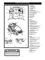
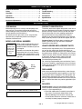
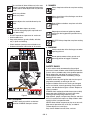
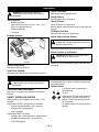
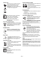
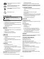
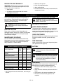
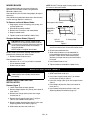
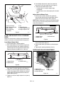
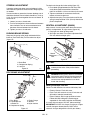
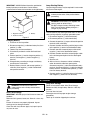
Yard Tractor
Owner/Operator Manual
Model
936034 - 1540
936036 - 2548
ENGLISH
FRANÇAIS
ESPAÑOL
03695200 10/02
Printed in USA
CONTROLS AND FEATURES
ENGLISH
16
5
4
15
14
7
6
2
17
18
9
13
1.
2.
3.
4.
5.
6.
7.
8.
9.
10.
11.
12.
13.
14.
15.
16.
17.
18.
19.
20.
21.
21
11
20
8
19
10
Fuel Tank Fill
Brake Pedal
Attachment Lift Lever
Throttle (936034)
Head Light Switch
Ignition/Key Switch
PTO Switch
Headlights
Parking Brake Latch
Fuel Level Indicator
Seat Position Adjustment Lever
Transmission Disconnect (Dump Valve)
Mower Height Indicator
Choke Control (936036)
Cruise Control Switch
Indicator Lights
Forward Pedal
Reverse Pedal
Anti-Scalp Roller
Deflector
Hood Latch
FRANÇAIS
3
1
1.
2.
3.
4.
5.
6.
7.
8.
9.
10.
11.
12.
13.
14.
15.
16.
17.
18.
19.
20.
21.
Réservoir d’essence
Pédale de frein
Levier de relevage de l’outil
Manette des gaz (936034)
Commande des phares
Démarrage/Clé de contact
Commande de la PdF
Phares
Verrouillage du frein de stationnement
Indicateur de niveau de carburant
Poignée de réglage du siège
Désenclenchement de la transmission
(soupape de décharge)
Indicateur de hauteur de coupe
de la tondeuse
Commande du starter (936036)
Régulateur de vitesse
Lampes témoin
Pédale de marche avant
Pédale de marche arrière
Rouleau anti-scalp
Déflecteur
Fermeture du capot
ESPAÑOL
936036
12
12
936034
OT0121
OT0181
OT1370
OT1371
Figure 1
WARNING
1.
2.
3.
4.
5.
6.
7.
8.
9.
10.
11.
12.
13.
14.
15.
16.
17.
18.
19.
20.
21.
The engine exhaust from this product
contains chemicals known to the State
of California to cause cancer, birth
defects or other reproductive harm.
OL4030
2
Llenado del depósito de combustible
Pedal del freno
Palanca de elevación del accesorio
Acelerador (936034)
Interruptor de los faros delanteros
Interruptor de arranque
Interruptor de la TDF
Faros
Traba del freno de estacionamiento
Indicador del nivel de combustible
Palanca de ajuste de la posición
del asiento
Desconexión de la transmisión (válvula
de descarga)
Indicador de altura del cortacésped
Control del estrangulador (936036)
Interruptor del piloto automático
Luces indicadoras
Pedal de desplazamiento hacia
adelante
Pedal de marcha atrás
Rodillo anti-desbroce
Deflector
Presilla del capó
QWEA
TABLE OF CONTENTS
Controls & Features . . . . . . . . . . . . . . . . . . . . . . . . . . 2
Storage . . . . . . . . . . . . . . . . . . . . . . . . . . . . . . . . . . . . 16
Safety . . . . . . . . . . . . . . . . . . . . . . . . . . . . . . . . . . . . . . 4
Troubleshooting . . . . . . . . . . . . . . . . . . . . . . . . . . . . . 17
Assembly . . . . . . . . . . . . . . . . . . . . . . . . . . . . . . . . . . . 8
Attachments . . . . . . . . . . . . . . . . . . . . . . . . . . . . . . . . 17
Operation . . . . . . . . . . . . . . . . . . . . . . . . . . . . . . . . . . . 8
Accessories . . . . . . . . . . . . . . . . . . . . . . . . . . . . . . . . 17
Maintenance. . . . . . . . . . . . . . . . . . . . . . . . . . . . . . . . 11
Specifications. . . . . . . . . . . . . . . . . . . . . . . . . . . . . . . 18
Service & Adjustments . . . . . . . . . . . . . . . . . . . . . . . 12
Warranty . . . . . . . . . . . . . . . . . . . . . . . . . . . . . . . . . . . 19
INTRODUCTION
THE MANUAL
PRODUCT REGISTRATION
Before operation of unit, carefully and completely read
your manuals. The contents will provide you with an
understanding of safety instructions and controls during
normal operation and maintenance.
All reference to left, right, front, or rear are given from
operator sitting in operation position and facing the
direction of forward travel.
The Ariens dealer must register the product at the time of
purchase. Registering the product will help the company
process warranty claims or contact you with the latest
service information. All claims meeting requirements
during the limited warranty period will be honored,
whether or not the product registration card is returned.
Keep a proof of purchase if you do not register your unit.
Customer Note: If the Dealer does not register your
product, please fill out, sign and return the product
registration card to Ariens.
MODEL AND SERIAL NUMBERS
Transfer
model & serial
number label
from product
registration
here.
When ordering replacement parts or
making service inquiries, know the
Model and Serial numbers of your unit
and engine.
Numbers are located on the product
registration form in the unit literature
package. They are printed on a serial
number label, located on the frame of
your unit.
Serial
Number
Label
Figure 2
•
•
OT0552
Record Unit Model and Serial numbers here.
Record Engine Model and Serial numbers here.
UNAUTHORIZED REPLACEMENT PARTS
Use only Ariens replacement parts. The replacement of
any part on this vehicle with anything other than an
Ariens authorized replacement part may adversely affect
the performance, durability, or safety of this unit and may
void the warranty. Ariens disclaims liability for any claims
or damages, whether warranty, property damage,
personal injury or death arising out of the use of
unauthorized replacement parts.
For a brief list of replacement parts see Service Parts in
this manual. To obtain a complete parts manual, find your
model and serial number. Then go to www.ariens.com or
call 1-800-678-5443.
DISCLAIMER
Ariens reserves the right to discontinue, make changes
to, and add improvements upon its products at any time
without public notice or obligation. The descriptions and
specifications contained in this manual were in effect at
printing. Equipment described within this manual may be
optional. Some illustrations may not be applicable to your
unit.
DELIVERY
Customer Note: If you have purchased this product
without complete assembly and instruction by your
retailer, it is your responsibility to:
1. Read and understand all assembly instructions in
this manual. If you do not understand or have
difficulty following the instructions, contact your
nearest Ariens Dealer for assistance. Make sure all
assembly has been properly completed.
GB - 3
© Copyright 2002 Ariens Company
NOTE: To locate your nearest Ariens Dealer, call
1-800-678-5443 or go to www.ariens.com on the internet.
3. Review control functions and operation of the unit.
Do not operate unit unless all controls function as
described in this manual.
4. Review recommended lubrication, maintenance
and adjustments.
5. Review Limited Warranty Policy.
6. Fill out the Product Registration Card and return the
card to Ariens Company or go to www.ariens.com.
WARNING: Improper assembly or adjustments
can cause serious injury.
2. Understand all Safety Precautions provided in the
manuals.
SAFETY
WARNING: This cutting machine is capable of
amputating hands and feet and throwing
objects. Failure to observe the safety
instructions in the manuals and on decals could
result in serious injury or death.
Slopes are a major factor related to
loss-of-control and tip-over accidents. Operation
on all slopes requires extra caution.
Tragic accidents can occur if the operator is not
alert to the presence of children. Never assume
that children will remain where you last saw
them.
Gasoline is extremely flammable and the vapors
are explosive, handle with care.
Disengage attachment, stop unit and engine,
remove key, engage parking brake, and allow
moving parts to stop before leaving operator’s
position.
SAFETY ALERTS
Look for these symbols to point out
important safety precautions. They mean:
CAUTION: POTENTIALLY HAZARDOUS
SITUATION! If not avoided, MAY RESULT in
minor or moderate injury. It may also be used to
alert against unsafe practices.
NOTATIONS
NOTE: General reference information for proper
operation and maintenance practices.
IMPORTANT: Specific procedures or information
required to prevent damage to unit or attachment.
PRACTICES AND LAWS
Practice usual and customary safe working precautions,
for the benefit of yourself and others. Understand and
follow all safety messages. Be alert to unsafe conditions
and the possibility of minor, moderate, or serious injury or
death. Learn applicable rules and laws in your area.
Always follow the practices set forth in this manual.
REQUIRED OPERATOR TRAINING
Personal Safety Is Involved!
Original purchaser of this unit was instructed by the seller
on safe and proper operation by the seller. If unit is to be
used by someone other than original purchaser; loaned,
rented or sold, ALWAYS provide this manual and any
needed safety training before operation.
Become Alert!
SAFETY DECALS AND LOCATIONS
Obey The Message!
ALWAYS replace missing or damaged Safety Decals.
Refer to figure 3 below for Safety Decal locations.
Attention!
The safety alert symbols above and signal words below
are used on decals and in this manual.
Read and understand all safety messages.
1. DANGER!
Read the operator’s manual.
Allow operation only by properly trained adult,
never children.
DANGER: IMMINENTLY HAZARDOUS
SITUATION! If not avoided, WILL RESULT in
death or serious injury.
OL1801
WARNING: POTENTIALLY HAZARDOUS
SITUATION! If not avoided, COULD RESULT in
death or serious injury.
OL4140
OL4740
GB - 4
DO NOT mow when children or others are
around.
Keep children out of work area and under
watchful care of a responsible adult.
Look down and behind before and while
backing.
DO NOT operate in reverse unless absolutely
necessary. Always back up slowly.
OL4750
Turn machine off when children are in the area.
Use extra care when approaching blind corners,
shrubs, trees or other objects that may obscure
vision.
3. DANGER!
Always keep feet and hands away from rotating
parts.
OL3030
Never carry children.
Never carry riders.
Always stand clear of the discharge area when
operating this unit.
OL4760
Remove objects that could be thrown by the
blade.
OL0910
Go up and down slopes, not across.
If machine stops going uphill, stop blade and
back down slowly.
OL4140
Keep children and others away from unit while
operating.
OL0910
10°
MAX
Stop engine and remove ignition key before
servicing or leaving operator’s position for any
reason.
OL4770
•
•
•
DO NOT operate on slopes over 10° maximum.
Avoid sudden turns.
Keep safety devices (guards, shields, switches,
etc.) in place and working.
Check interlock system per manual before use.
Understand location and function of all controls.
•
•
1
OL4010
NO STEP! Always keep feet away from rotating
parts.
OL4420
4. WARNING!
DANGER / PELIGRO
Always stand clear of the discharge area when
operating this unit.
10°
OL4430
Do not operate mower unless guards are in
operating position or bagger is attached.
POUR EVITER LES BLESSURES
GRAVES OU LA MORT
• Lire le manuel d'utilisation.
• Éloigner les enfants et toute autre personne pendant le
fonctionnement de la machine.
• Regardez derriere et sur les cotes lorsque vous reculez.
• Ne transportez jamais dénfant.
• Ne jamais décharger directement en direction de
quelqu’un. Des particules projetées peuvent provoquer
des blessures.
• Tondez toujours de haut en bas et inversement jamais le
long des pentes.
• Si la machine sárrete en montee. Debrayez la lame et
redescendez doucement.
• Evitez les virages brusques.
• Maintenez toujours en place tous les elements de securite
(protecteurs, interupteurs, etc.).
• Controlez le bon fonctionnement des interrupteurs de securité
avant utilisation tel q'uindiqué dans le manuel d'utilisation.
• Comprenez bien la fonction et la situation de chacun des leviers
et boutons de commande.
TO AVOID SERIOUS INJURY
OR DEATH
• Read the operator's manual.
• Keep children and others away from unit
while operating.
• Look down and behind before and while
backing.
• Never carry children.
• Never direct discharge toward other
people. Thrown objects can cause injury.
• Go up and down slopes, not across.
• If machine stops going uphill, stop blade
and back down slowly.
• Avoid sudden turns.
• Keep safety devices (guards, shields,
switches, etc.) in place and working.
• Check interlock system per manual
before use.
• Understand location and function of all
controls.
PARA EVITAR DAÑOS SERIOS
O LA MUERTE
• Leer el manual del operador.
• Mantenga la unidad alejada de los niños u otras
personas cuando esté en funcionamiento.
• Antes y durante retroceso mirar hacia abajo y
detras.
• Nunca monten niños.
• Nunca dirija la descarga hacia otras personas, ya
que los objetos lanzados pueden provocar lesiones.
• Suba y baje pendientes, no transversalmente.
• Si la maquina se detiene subiendo cuesta, desactive la
cuchilla y baje lentamente.
• Evite viradas subitas.
• Mantenga artefactos de seguridad (defensas,
protectores, interruptores, etc.) en su lugar y trabajando.
• Verifique en el manual el sistema de engranar antes de
usar.
• Tenga conocimiento de funciones y localizaciones de todos
los controles.
OL3320
SAFETY RULES
08086600
2
4
WARNING/AVERTISSEMENT/ADVERTENCIA
07742300B
Do not operate mower Ne jamais utiliser
unless guards are in
la tondeuse sans
operating position or protecteur sur le
bagger is attached.
canal d'ejection ou
sans le bac monte.
No operar segadora a
menos que las defensas
esten en posicion de
operacion o el
recogedor este fijo.
3
DANGER/PELIGRO
07731400D
Figure 3
OT0563
2. HOT SURFACES!
DO NOT touch parts which are hot from
operation. ALWAYS allow parts to cool.
OD0061
If unit is to be used by someone other than original
purchaser; loaned, rented or sold, ALWAYS provide this
manual and any needed safety training before operation.
Read, understand, and follow all safety practices in
Owner/Operator Manual before assembling, using or
working on this mower.
ALWAYS remove key from ignition and wire from spark
plug before assembly, or working on this unit.
Inspect unit before each use for: missing or damaged
decals and shields, correctly operating safety interlock
system, and deterioration of grass catchers. Replace or
repair as needed.
ALWAYS check overhead and side clearances carefully
before operation. ALWAYS be aware of traffic when
crossing or operating along streets or curbs.
Keep children, people, and pets away. Be alert and shut
off unit if anyone enters work area. Keep children under
watchful care of a responsible adult.
NEVER allow children to operate or play on or near unit.
Keep area of operation clear of all toys, and debris.
Thrown objects can cause injury.
Stay alert for hidden hazards, holes, and ruts.
GB - 5
Avoid uneven or rough terrain. DO NOT operate near
drop offs, ditches, or embankments. Unit can suddenly
turn over if a wheel is over the edge of a cliff or ditch, or if
an edge caves in.
Dust, fog, etc. can reduce vision and cause an accident.
Operate unit only when there is good visibility and light.
Data indicates that operators, age 60 and above, are
involved in a larger percentage of riding mower related
injuries. These operators should evaluate their ability to
operate the riding mower safely enough to protect
themselves and others from serious injury.
Only trained adults may operate unit. Training includes
being familiar with controls and actual operation.
NEVER operate unit after or during the use of
medication, drugs or alcohol.
NEVER allow anyone to operate this unit when their
alertness or coordination is impaired.
Wear adequate safety gear, sturdy shoes, and protective
gloves.
DO NOT wear loose clothing or jewelry and tie back hair
that may get caught in rotating parts.
Protect eyes, face and head from objects that may be
thrown from unit. Wear appropriate hearing protection.
Always wear safety goggles or safety glasses with side
shields when operating mower.
Avoid sharp edges. Sharp edges can cut. Moving parts
can cut off fingers or a hand.
ALWAYS keep hands and feet away from all rotating
parts during operation. Rotating parts can cut off body
parts.
ALWAYS keep hands away from all pinch points.
DO NOT touch unit parts which might be hot from
operation. Allow parts to cool before attempting to
maintain, adjust or service.
NEVER place your hands or any part of your body or
clothing inside or near any moving part while unit is
running.
NEVER direct discharge towards persons or property.
Thrown objects may ricochet back towards
operator.ALWAYS stand clear of the discharge area.
ALWAYS disengage attachment, stop unit and engine,
remove key, engage parking brake, and allow moving
parts to stop before leaving operator’s position.
Use extreme caution on gravel surfaces.
Disengage PTO when attachment is not in use and when
crossing gravel surfaces.
DO NOT operate unit if safety interlock system is
damaged or disabled. Check safety interlock before each
use (see Operation on page 8).
ALWAYS remove key to prevent unauthorized use.
DO NOT operate at too fast a rate. Slow down before
turning.
Stop engine before removing grass catcher or unclogging
chute.
DO NOT mow on wet grass. Reduced traction could
cause sliding.
DO NOT try to stabilize the machine by putting your foot
on the ground.
Know the weight of loads. Limit loads to those you can
safely control and the unit can safely handle.
ALWAYS keep protective structures, guards and panels
in good repair, in place and securely fastened.
Do not operate without either entire grass catcher or the
discharge guard in place.
DO NOT operate in reverse unless absolutely necessary.
ALWAYS look down and behind before and while
backing; especially for children.
Follow the manufacturer’s recommendations for wheel
weights or counterweights to improve stability when using
attachments.
NEVER carry passengers–especially children–even with
blades off.
Use extra care when approaching blind corners or
objects that may obscure vision of hidden obstacles and
children.
If you cannot back up a slope or you feel uneasy on it, do
not mow it.
Mow up and down slopes, not across them.
Use slow speed on any slope. Tires may lose traction on
slopes even though the brakes are functioning properly.
Keep all movements on the slope slow and gradual. DO
NOT make sudden changes in speed or direction.
Use extra care while operating machines with grass
catcher or other attachments. They can affect stability of
the machine.
Avoid starting, stopping, or turning on a slope. If tires lose
traction, disengage the blades and proceed slowly
straight down the slope.
DO NOT operate on slopes over 10˚.
DO NOT park on slopes unless necessary. If unit is
parked on a slope, ALWAYS chock or block wheels and
set parking brake.
DO NOT disengage or bypass transmission and coast
downhill.
Tow only with a machine that has a hitch designed for
towing. Do not attach towed equipment except at the
hitch point.
Follow the manufacturer’s recommendations for weight
limits for towed equipment and towing on slopes.
NEVER allow children or others in or on towed
equipment.
On slopes, the weight of the towed equipment may cause
loss of traction and loss of control.
Travel slowly and allow extra distance to stop.
Use extra care when loading or unloading unit onto trailer
or truck.
Secure unit chassis to transport vehicle. NEVER secure
from rods or linkages that could be damaged.
GB - 6
DO NOT transport machine while engine is running.
Keep unit free of grass clippings, leaves, and other
debris. Clean up oil or fuel spills.
This product is equipped with an internal combustion
type engine. DO NOT use unit on or near any
unimproved, forest-covered or brush covered land unless
exhaust system is equipped with a spark arrester
meeting applicable local, state or federal laws. A spark
arrester, if it is used, must be maintained in effective
working order by operator.
Fuel is highly flammable and its vapors are explosive.
Handle with care. Use an approved fuel container.
NO smoking, NO sparks, NO flames. ALWAYS allow
engine to cool before servicing.
NEVER fill fuel tank when engine is running or hot from
operation.
NEVER fill or drain fuel tank indoors.
NEVER overfill fuel tank.
Replace fuel cap securely and clean up spilled fuel.
NEVER fill containers inside a vehicle or on a truck or
trailer bed with a plastic liner. Always place containers on
the ground away from your vehicle before filling.
When practical, remove gas-powered equipment from
the truck or trailer and refuel it on the ground. If this is not
possible, then refuel such equipment on a trailer with a
portable container, rather than from a gasoline dispenser
nozzle.
Keep the nozzle in contact with the rim of the fuel tank or
container opening at all times until fueling is complete.
Do not use a nozzle lock-open device.
If fuel is spilled on clothing, change clothing immediately.
Avoid Electric Shock. Objects contacting both battery
terminals at the same time may result in injury and unit
damage. DO NOT reverse battery connections.
Explosive Gases from battery can cause death or serious
injury. Poisonous battery fluid contains sulfuric acid and
its contact with skin, eyes or clothing can cause severe
chemical burns.
NO flames, NO sparks, NO smoking near battery.
ALWAYS wear safety glasses and protective gear near
battery.
DO NOT TIP battery beyond a 45˚ angle in any direction.
ALWAYS keep batteries out of reach of children.
Battery posts, terminals and related accessories contain
lead and lead compounds, chemicals known to the State
of California to cause cancer and reproductive harm.
Wash hands after handling.
Reverse connections may result in sparks which can
cause serious injury. Always connect positive (+) lead of
charger to positive (+) terminal, and negative (-) lead to
negative (-) terminal.
ALWAYS disconnect negative (-) cable FIRST and
positive (+) cable SECOND. ALWAYS connect positive
(+) cable FIRST, and negative (-) cable SECOND.
A frozen battery can explode and result in death or
serious injury. DO NOT charge or jump start a battery
containing frozen fluid. Thaw the battery before putting on
a charger or jump starting.
ALWAYS keep protective structures, guards, and panels
in good repair, in place and securely fastened. NEVER
modify or remove safety devices.
DO NOT change engine governor settings or over-speed
engine.
Fumes from engine exhaust can cause injury or death.
DO NOT run engine in an enclosed area. Always provide
good ventilation.
ALWAYS maintain unit in safe operating condition.
Damaged or worn out muffler can cause fire or explosion.
Stop and inspect equipment if you strike an object or if
there is an unusual vibration. Repair, if necessary, before
restarting. Never make adjustments or repairs with the
engine running.
Mower blades are sharp and can cut you. Wrap the
blade(s) or wear gloves, and use extra caution when
servicing them. NEVER weld or straighten mower blades.
Rotation of one blade may cause rotation of the other
blades.
Check brake operation frequently. Adjust and service as
required.
Keep all hardware properly tightened.
Stored energy in springs can cause injury.
Maintain or replace safety and instruction labels, as
necessary.
Never store the machine or fuel container inside a
building where there is an open flame, such as a water
heater.
Allow engine to cool completely before storing in closed
area or covering unit.
For extended storage, clean unit thoroughly. See Engine
Manual for proper storage.
Use only attachments or accessories designed for your
unit.
Check attachment components frequently. If worn or
damaged, replace with manufacturer’s recommended
parts.
GB - 7
ASSEMBLY
WARNING: AVOID INJURY. Read and
understand the entire Safety section before
proceeding.
•
•
See General Lubrication on page 12.
Charge Battery
See Charging Battery on page 16.
Tools Required
•
•
Check Lubrication
Needle nose pliers
Open-end wrench: 3/8 in., 7/16 in., 1/2 in., and
9/16 in. or adjustable wrench
Phillips screwdriver
Tire gauge
Check Oil Level
Check engine oil. Fill if necessary.
Refer to engine manual for proper type oil and crankcase
capacity.
Fill Engine Fuel Tank
Refer to engine manual for proper type.
Package Contents
Check Safety Interlock System
Tractor and
Deck
Ha
r
Lit dwa
era re
/
Pa ture
ck
WARNING: FAILURE OF INTERLOCK,
together with improper operation could result in
death or serious injury.
See Check Safety Interlock System on page 11.
Check Function of all Controls
WARNING: FAILURE OF CONTROLS could
result in death or serious injury.
Figure 4
Ensure unit runs and performs properly (see Operation
on page 8)
Check Tire Pressure
See Specifications on page 18.
Install Deck (936036)
See Mower Deck Removal and Installation on page 12.
OPERATION
WARNING: AVOID INJURY. Read and
understand the entire Safety section before
proceeding.
DO NOT operate unit unless safety interlock system is
functioning properly. If it does not function properly, see
your Ariens Dealer.
Ignition Switch
CONTROLS AND FEATURES
1
See Figure 1 on page 2 for all Controls and Features
locations.
2
3
SAFETY INTERLOCK SYSTEM
With operator on seat, engine must not start if PTO is
engaged.
Engine MUST STOP if operator leaves seat when:
• forward and reverse pedal is not in neutral or
OT0680
• parking brake is disengaged or
• PTO is engaged
Engine MUST NOT start unless:
• parking brake is set/brake pedal is depressed and
• forward and reverse pedal is in neutral and
• PTO is disengaged.
GB - 8
The ignition switch is operated by a
removable key.
To start:
Insert the key. Turn the switch clockwise
from the off (1) position to the start (3)
position. The key will spring back to the
run (2) position.
To stop the engine, turn key to the off (1)
position.
Forward and Reverse Pedal
Throttle Lever
Move lever to fast (1) position to increase
engine speed. Move lever to slow (2)
position to decrease engine speed.
IMPORTANT: Set throttle to approximately
1/2 speed when engaging PTO.
1
OT1580
Press the front end of pedal downward to
move tractor forward.
Press the rear end of pedal downward to
move the tractor backward.
Removing foot from pedal returns unit to
neutral.
Seat Adjustment
1. Move the handle on the seat towards the center of
the tractor.
2. Slide seat into a comfortable position.
3. Release handle to lock seat in position.
2
Choke
Apply choke when starting a cold engine.
To apply choke on model 936034:
Place throttle lever in choke position.
To apply choke on other models:
Pull choke knob out. Press knob in to
disengage choke.
Transmission Bypass Lever
Power Take-Off (PTO) Switch
The power take-off switch is used to engage
and disengage the attachment. Lift switch to
engage attachment. Push switch down to
disengage attachment.
OT0710
Cruise Control Switch
Use the cruise control switch to maintain
desired speed. Depress forward pedal to
desired speed and push the cruise control
switch forward to engage (1).
Flip cruise control switch back or depress
2
OT0640
brake pedal to disengage (2) cruise control.
NOTE: Turning off cruise control switch
without foot on forward or reverse pedal will stop unit
abruptly.
IMPORTANT: If the forward pedal or reverse pedal is
repositioned while cruise indicator light is on, cruise will
reset at the new speed and/or direction selected.
1
Headlight Switch
With key in run position, flip light switch
forward (1) to turn headlights on. Flip light
switch backward (2) to turn headlights off.
1
2
OT0610
Brake Pedal
OT0650
Fully depress brake pedal to stop unit.
IMPORTANT: DO NOT leave foot on pedal
during operation as belt slippage may
occur.
Attachment Lift Lever
OT0620
Pull bypass lever rearward and lock in slot
to disengage transmission (2). Pull lever
out of slot and slowly release forward to
2
engage transmission (1).
OT0630
IMPORTANT: Start unit with transmission
bypass lever in disengaged position when starting engine
in freezing temperatures (below 32˚F/0˚C). Slowly
engage transmission, allowing transmission to warm up
before applying load.
1
To raise attachment, depress thumb button
on lift lever and raise lever to raise
attachment.
To lower attachment, depress thumb button
and slowly allow lever to move downward to
lower attachment.
Hood
To open, push hood latch to the right, lift hood and place
prop rod in slot under hood.
To close, remove prop rod from slot and lower it to side of
engine. Lower the hood until it rests on the latch. Press
down firmly at the center of the hood to snap it into latch.
Indicator Lights
The symbols on the dash will light up when key is turned
to the run position if one of the following conditions exist:
Parking Brake
P
To engage:
Fully depress brake pedal and pull parking
brake knob out.
To disengage:
Depress brake pedal.
GB - 9
7. Release brake pedal.
8. Allow engine to warm up before applying load.
IMPORTANT: Run engine at 1/2 throttle for at least five
minutes prior to applying load in freezing temperatures.
Battery voltage is lower than 12V. Refer to
Maintenance.
BATTERY
Oil pressure is low. Check oil and add if
necessary. See Engine Manual.
TO OPERATE MOWER
PTO is engaged. Disengage PTO before
starting tractor.
1. With unit shut off, adjust deck to desired height of
cut.
2. Start engine.
3. Move throttle lever to about half speed.
4. Engage PTO.
5. Move the throttle lever forward to full engine speed.
6. Use forward and reverse pedals to move and use
steering wheel to change direction.
7. To stop mower, disengage PTO.
Safe condition to start.
FILLING FUEL TANK
WARNING: AVOID INJURY. Read and
understand the entire Safety section before
proceeding.
SHUT-OFF
Emergency Shut-Off
To add fuel to fuel tank:
1. ALWAYS place unit in open or well ventilated area.
2. Stop engine and allow to cool.
3. Clean fuel cap and surrounding area to prevent dirt
from entering fuel tank.
4. Remove cap.
IMPORTANT: See engine manual for correct type and
grade of fuel.
5. Fill fuel tank to within 1/2 in. (1,2 cm) below bottom
of filler neck.
6. Replace fuel cap and tighten.
7. ALWAYS clean up any spilled fuel.
To shut-off unit in an emergency, turn ignition key to the
off position.
Normal Shut-Off
1.
2.
3.
4.
5.
Turn off cruise control.
Stop unit.
Disengage PTO.
Lower attachment and engage parking brake.
Lower engine speed to slow position. Let engine
run a few minutes so engine parts cool evenly
before shutting engine off.
6. Turn ignition key to off position and remove key.
PARKING
PRESTART
Stop engine and engage parking brake to park. Remove
ignition key to prevent unauthorized use.
Before starting:
1. Check engine oil and fill if necessary. See engine
manual.
2. Check fuel and fill if necessary.
3. Check safety interlock system. See Controls and
Features.
4. Adjust seat if needed.
FOR BEST PERFORMANCE:
STARTING
1. Sit in the operator’s seat.
2. Place the PTO knob in the off position.
3. Apply choke for a cold engine, place at 1/3 throttle
for a warm engine.
4. Press down brake pedal.
5. Turn the ignition key clockwise to the start position
until engine starts. Release key into run position.
IMPORTANT: DO NOT operate starter more than 15
seconds per minute. Damage can occur.
6. After engine starts, set throttle to fast position.
Cut grass when it is dry.
Keep mower blades sharp.
Keep mower deck properly leveled.
Adjust anti-scalp rollers to prevent scalping.
Do not set height of cut too low. For very tall grass, mow
twice.
Do not travel too fast.
Mow with the engine set at full throttle.
When mulching, only remove 1/3 of grass length per
cutting.
Discharge clippings into areas already cut.
Vary cutting pattern with each mowing.
Do not allow grass or debris to collect inside of mower
deck. Clean after each use.
GB - 10
MOVING THE UNIT MANUALLY
3.
4.
5.
6.
IMPORTANT: DO NOT push or pull (tow) tractor with
another vehicle. Transmission damage will occur. Use
truck or trailer when transporting.
1. Stop engine.
2. Pull bypass lever rearward and lock in slot to
disengage transmission.
Release parking brake.
Push unit to desired location.
Apply parking brake.
Pull lever out of slot and slowly release forward to
engage transmission.
MAINTENANCE
CHECK SAFETY INTERLOCK SYSTEM
Ariens Dealers will provide any service or adjustments
which may be required to keep your unit operating at
peak efficiency. Should engine service be required,
contact an Ariens dealer or an authorized engine
manufacturer's service center.
WARNING: FAILURE OF INTERLOCK,
together with improper operation could result in
death or serious injury.
WARNING: AVOID INJURY. Read and
understand the entire Safety section before
proceeding.
See Filling Fuel Tank on page 10.
CHECK PARKING BRAKE
SERVICE POSITION
Place unit on a flat level surface. Stop engine and
disengage clutches. Assure unit is secure and will not tip
over. Strap and clamp onto lift if used. Open hood to
access battery or engine.
The chart below shows recommended maintenance.
More frequent service may be required due to working
conditions (heavy loads, high ambient temperatures,
dusty conditions, or airborne debris).
TIRE PRESSURE
Check air pressure in all tires every 25 operating hours
(see Specifications on page 18).
MAINTENANCE SCHEDULE
Service Performed
Check Safety Interlock
System
•
Check Parking Brake
•
Check Fasteners
•
Check Engine Oil**
•
Every
25 hrs.
CHECK FASTENERS
Be certain all hardware is tightened to the proper torque.
Pay special attention to blades, guards and safety
shields.
MAINTENANCE SCHEDULE
Before
Each
Use
The parking brake is designed to prevent unexpected
movement of the unit. If the parking brake allows unit
movement while engaged for proper parking brake spring
setting (see Parking Brake Spring on page 15).
BATTERY
Every
50 hrs.
WARNING: AVOID INJURY. Read and
understand the entire Safety section before
proceeding.
WARNING: Battery posts, terminals and related
accessories contain lead and lead compounds,
chemicals known to the State of California to
cause cancer and reproductive harm. Wash
hands after handling.
Change Engine Oil**
•*
Tire Pressure
•
Clean Battery
Battery
•
Mower Blades
•
Keep battery and its terminals clean. Inspect every 25
operating hours or monthly for best performance.
1. Disconnect cables from battery (negative, then
positive).
2. Clean terminals and battery cable ends with wire
brush.
3. Coat terminals with grease or petroleum jelly.
4. Reconnect cables to battery (positive, then
negative).
General Lubrication
•
* Change after first 5 to 8 hours of use.
** For all engine maintenance information, refer to engine
manual.
GB - 11
MOWER BLADES
Check mower blades for wear every 25 hours of
operation. Ensure blade hardware is tightened to
50-60 lbf-ft (68-81 N•m).
Check blade for nicks and dull cutting edges. Sharpen if
necessary.
Check blade for rounded or broken ends, thinned metal
or other damage. Replace if necessary.
To Remove and Install Mower Blade:
NOTE: DO NOT change angle of cutting edge or round
the corner of the mower blade.
DO NOT Resharpen to this Pattern
Resharpen to this Pattern
1. Stop engine, wait for all moving parts to stop, and
remove ignition key.
2. Block blade to prevent rotation.
3. Remove nut, flat washer, and mower blade.
4. Replace mower blade.
5. Tighten hardware to 50-60 lbf-ft (68-81 N•m).
DISCARD if
more than
1/2 in.
(1.27 cm)
1
OA0014
2
Sharpen the Mower Blades (Figure 5)
1. Air Lift
Erosion Area
CAUTION: DO NOT sharpen mower blades
while on unit. An unbalanced mower blade will
cause excessive vibration and eventual damage
to unit. Check mower blade balance before
reinstalling blades.
NEVER weld or straighten bent blades.
2. Cutting Edge
Figure 5
2. Sharpen mower blade by removing an equal
amount of material from each end of mower blade.
3. Check mower blade balance.
4. Slide mower blade on an unthreaded bolt. A
balanced blade should remain in a horizontal
position. If either end of mower blade moves
downward, sharpen the heavy end until blade is
balanced.
5. Install mower blade on unit.
6. Tighten hardware to 50-60 lbf-ft (68-81 N•m).
NOTE: Blades should be sharpened and balanced
professionally. Contact your Ariens Dealer.
1. Remove mower blade from unit.
Discard mower blade if:
• More than 1/2 in. (1.27 cm) of metal is removed.
• Air lifts become eroded.
• Blade is bent or broken.
SERVICE AND ADJUSTMENTS
Install (figure 7)
WARNING: AVOID INJURY. Read and
understand the entire Safety section before
proceeding.
MOWER DECK REMOVAL AND
INSTALLATION
Remove (figure 7)
1. Lower mower deck to lowest position.
2. Remove height adjuster link (item 8) from center lift
lever (item 1).
3. Remove rear hanger (item 3) from rear hanger
bracket (item 2).
4. Remove front hanger bracket (item 7) and pin
(item 5) from slotted bracket (item 6).
5. Remove mower drive belt from electric clutch (see
Replacing Mower Drive Belt on page 14).
6. Slide mower deck out from under unit.
GB - 12
1. Slide mower deck under unit.
2. Install front hanger bracket (item 7) on slotted
bracket (item 6) with pin (item 5).
3. Install rear hanger (item 3) on rear hanger bracket
(item 2).
4. Install height adjuster link (item 8) on center lift
lever (item 1).
5. Install mower drive belt on electric clutch (see
Replacing Mower Drive Belt on page 14).
6. Install height adjuster link (item 8) on center lift
lever (item 1) on each side of the unit (figure 7).
7. Check that the mower deck is level.
• If mower deck is not level, repeat steps
3 through 6.
• If mower deck is level, then adjust pitch of mower
deck.
1
8
7
2
6
Adjust Pitch of Mower Deck
1. With the end of mower blades facing forward,
measure the distance from mower blade and the
ground at the front of mower deck. (figure 9).
NOTE: Adjust mower pitch so front end of mower blade is
1/8 in. to 1/4 in. (3 mm to 6 mm) lower than back end of
mower blade (figure 9).
5
3
4
1. Center Lift Lever
2. Rear Hanger Bracket
3. Rear Hanger
4. Pitch Adjusting
Hardware
Front
5. Pin
6. Slotted Bracket
7. Front Hanger Bracket
8. Height Adjuster Link
2
1
3
Figure 7
OT1080
1/8-1/4 in. (3 - 6 mm) lower
LEVEL AND ADJUST PITCH OF MOWER
DECK
1. Mower Blade
2. Mower Deck
Adjust on a level surface, with the tires inflated to the
correct air pressure (see Specifications on page 18).
3. Ground Level
Figure 9
2. Loosen pitch adjusting hardware (item 4) on each
side of mower deck (figure 7).
3. Adjust mower deck up or down to achieve proper
pitch.
4. Tighten pitch adjusting hardware (item 4).
Level Mower Mower Deck
1. Place mower deck in highest position.
2. With mower blades in line with discharge chute,
measure the distance from mower blade to the
ground on the left and right side of mower deck
(figure 8). Distance should be 4 in. (10.2 cm).
ANTISCALP ROLLER ADJUSTMENT
2
1
OT1820
1
2
3
5
4 in. (10.2 cm)
1. Mower Blade
2. Mower Deck
3
3. Ground Level
OT1810
4
Figure 8
3. Remove height adjuster link (item 8) from center lift
lever (item 1) on each side of the unit (figure 7).
4. Loosen jam nuts on height adjuster links (item 8)
and turn the adjuster links clockwise to raise the
mower deck and counterclockwise to lower the
mower deck (figure 7).
5. Tighten jam nuts on height adjuster links (item 8)
(figure 7).
GB - 13
1. Mower Deck
2. Mounting Hardware
3. Antiscalp Roller
4. Pin
5. Roller Clevis
Figure 10
IT0860
IMPORTANT: Antiscalp rollers prevent lawn scalping. DO
NOT use antiscalp rollers to set cutting height. Adjust
antiscalp rollers to same height as mower blade or
higher. Adjust all antiscalp rollers to same height.
NOTE: Adjust on a level surface, with the tires inflated to
the correct air pressure (see Specifications on page 18).
1. Select cutting height.
2. Adjust all antiscalp rollers (item 3) to within 1/2 in.
(1.27 cm) of ground (figure 10).
2
4
3. Mower Belt
4. Jackshaft Pulley
5. Deck Idler Spring
Figure 12
OT1400
TRACTION DRIVE BELT
See figure 11 or figure 12.
1. Remove mower drive belt.
2. Disconnect idler spring from spring mount welded
to the mower deck.
3. Remove left sheave cover.
4. Remove old belt from mower deck and install new
belt. Ensure belt is seated in all pulley grooves.
5. Replace left sheave cover, reconnect idler spring
and replace mower drive belt.
3
5
1. Idler
2. Mower Pulley
REPLACING DECK BELT
5
3
1
REPLACING MOWER DRIVE BELT
The mower belt idler system is designed to provide
constant tension on the belt. If the deck idler spring is
extended less than 4 1/2 in. (11.4 cm), replace the mower
drive belt.
1. Disconnect deck idler spring from frame.
2. Remove belt from electric clutch and mower pan
sheave.
3. Place new belt on electric clutch and mower pan
sheave.
4. Reconnect deck idler spring to frame.
40 in. Deck
2
1. Loosen hardware securing belt fingers at idler and
pulleys (figure 13).
2. Depress clutch/brake pedal and remove belt from
idler and pulleys.
3. Install new belt in reverse order.
4. Secure belt finger hardware with 1/16 in. to 1/8 in.
(2 to 3 mm) clearance between belt fingers and
belt.
6
1
2
6
5
3
48 in. Deck
2
2
7
6
2
7
4
7
1
4
1. Idler
2. Mower Pulley
3. Mower Belt
4. Jackshaft Pulley
5. Deck Idler Spring
6. Mower Idler Pulley
Figure 11
1. Engine Sheave
2. V-Idler
3. Clutch Idler Arm
OT0930
GB - 14
4. Transaxle Pulley
5. Traction Drive Belt
6. Belt Finger
7. Belt Guide
Figure 13
OT0061
STEERING ADJUSTMENT
If steering system feels loose, ensure hardware is tight
and check wear points for excessive wear. Replace parts
as needed.
If tractor wanders or excessive tire wear develops, toe-in
should be checked. Front of wheels should be 1/16 in. to
1/8 in. (2 to 3 mm) closer together than rear of wheels. To
correct toe-in:
1. Loosen jam nuts at tie rod ends.
2. Turn tie rod clockwise to increase distance between
front of wheels. Turn tie rod counterclockwise to
decrease distance between front of wheels.
3. Tighten jam nuts at tie rod ends.
PARKING BRAKE SPRING
Compress the spring to the length indicated with the
brake on (Park Brake Set). Turn the locknut to adjust
(figure 14).
To check and change disc brake setting (figure 15):
1. Place feeler gauge between the two discs. With
clutch/brake pedal released there should be
0.015 in. to 0.025 in. (0.4 mm to 0.6 mm) clearance.
2. Tighten castellated nut to decrease clearance,
loosen to increase clearance.
3. Adjust brake spring. Turn nylon locknut until brake
spring is compressed to 7/8 in. (22 mm) when brake
pedal is depressed.
NEUTRAL ADJUSTMENT (936036)
Adjust neutral if tractor moves when forward or reverse
pedal is not depressed. To adjust neutral (figure 16):
1. Prop right rear wheel off the ground.
2. Spin right rear wheel. Turn neutral adjustment bolt
until rear wheel no longer spins.
1-13/16 in. (4.6 cm)
3
Neutral
Adjustment
Bolt
2
Figure 16
1
OT0041
BATTERY
1. Brake Rod
2. Compression Spring
3. Lock Nut
Figure 14
WARNING: AVOID INJURY. Read and
understand the entire Safety section before
proceeding.
OT0351
DISC BRAKE ADJUSTMENT
WARNING: Battery posts, terminals and related
accessories contain lead and lead compounds,
chemicals known to the State of California to
cause cancer and reproductive harm. Wash
hands after handling.
7/8 in.
22 mm
6
2
3
Battery Electrolyte First Aid
5
1
4
1. Disc Brake
2. Castellated Nut
w/Cotter Pin
3. Compression Spring
4. Feeler Gauge
5. Washer
6. Nylon Locknut
Figure 15
OT0840
Follow First Aid directions for contact with battery fluid.
• External Contact: Flush with water.
• Eyes: Flush with water for at least 15 minutes and
get medical attention immediately!
• Internal Contact: Drink large quantities of water.
Follow with Milk of Magnesia, beaten egg or
vegetable oil. Get medical attention immediately!
In case of internal contact, DO NOT induce vomiting!
IMPORTANT: DO NOT fast charge. Charging at a higher
rate will damage or destroy battery. ONLY use an
automatic charger designed for use with your battery.
GB - 15
IMPORTANT: ALWAYS follow information provided on
battery by battery manufacturer. Contact battery
manufacturer for extensive instructions to charge battery.
Jump Starting Battery
Jump starting the battery may be required if starter motor
will not crank the engine.
WARNING: AVOID INJURY. Read and
understand the entire Safety section before
proceeding.
2
1
WARNING: Frozen battery can explode and
result in death or serious injury.
DO NOT charge a battery containing frozen
fluid. Thaw the battery before putting on a
charger or jump starting.
3
1. Negative terminal
2. Positive terminal
3. Battery
Figure 17
OF1671
Charging Battery
1. Place unit in service position.
2. Disconnect negative (-) cable from battery first, then
positive (+) cable.
3. Loosen strap and remove battery.
4. Place battery on bench or other well-ventilated
place.
5. Connect positive (+) lead of charger to positive (+)
terminal, and negative (–) lead to negative (–)
terminal.
6. Charge battery according to charger and battery
manufacturers’ instructions.
7. Reinstall battery into unit and connect positive (+)
cable first, then negative (–) cable. Position boot
over positive terminal.
The unit used for jump starting should have a 12 volt, 500
cold cranking amperes, negatively grounded system.
1. Disconnect negative (-) cable from battery.
2. Disconnect positive (+) cable from battery.
3. Connect the positive (+) jumper cable to the positive
terminal of the unit battery.
4. Connect the other end of the positive jumper cable
to the positive (+) terminal of the booster battery.
5. Connect one end of second jumper cable to the
negative (-) terminal of the booster battery.
6. Connect the other end of the second jumper cable
to the furthest ground point from the discharged
battery.
7. Start the unit.
8. After unit starts, disconnect cables in following
order: disconnect cable from ground point,
disconnect negative (-) cable from booster battery
terminal, disconnect positive (+) cable from booster
battery terminal, and disconnect positive (+) cable
from unit battery terminal.
9. Connect positive (+) cable first from unit to battery,
then negative (-) cable from unit to battery.
STORAGE
Long Term Storage
WARNING: AVOID INJURY. Read and
understand the entire Safety section before
proceeding.
Short Term Storage
IMPORTANT: NEVER spray unit with water or store unit
outdoors.
Remove all dirt, grease, leaves, etc. Store in a clean, dry
area.
Ensure all fasteners are properly tightened. Inspect
moving parts for damage and wear.
Clean seat with vinyl cleaner. Apply vinyl repair tape to
any tears on seat.
Follow all instructions under Short Term Storage.
Remove and fully charge battery. Store in a cool, dry
location.
Drain fuel from fuel tank.
See engine manual for proper engine storage
procedures.
Touch up all rusted or chipped paint surfaces.
GB - 16
TROUBLESHOOTING
PROBLEM
PROBABLE CAUSE
CORRECTION
Engine will not
crank/start
1.
2.
3.
4.
5.
Engine stops
1. Out of fuel.
2. See engine manual.
Engine problems
1. See engine manual.
Does not operate
in forward/reverse
1. Transmission is disengaged.
2. Clutch needs adjustment.
1. Engage transmission using bypass lever.
2. See Ariens Dealer.
Engine runs
roughly
1. Choke engaged.
2. Air cleaner clogged.
1. Disengage choke.
2. Replace air cleaner. See engine manual.
PTO is engaged.
Brake not engaged.
Discharged battery.
Loose battery cables.
Fuel tank is empty.
1. Disengage PTO.
2. Depress clutch/brake pedal while starting.
3. Charge battery (see Charging Battery on
page 16).
4. Check battery connections.
5. Fill fuel tank.
1. Fill fuel tank.
ACCESSORIES
SERVICE PARTS
See your authorized Ariens dealer to add these optional
accessories to your unit.
Part No.
Description
73600900
Rear Mounted Weight Box
73600200
Tire Chains 20 x 8-8 Tires
73600300
Rear Wheel Weights - 40 lbs.
73601000
73600700
Dethatcher - 40 in.
73600800
Hourmeter Kit
Part No.
01554800
07229600
07211500
07235200
07229700
03624700
03123700
To obtain a complete parts manual, find your model and
serial number. Then go to www.ariens.com or call
1-800-678-5443.
ATTACHMENTS
Part No.
Description
83600800
Three Bucket Bagger
83601100
36 in. Sno Thro
Description
Battery
PTO (Engine to Deck) Belt
Mower Deck Belt (40 in. Deck)
Mower Deck Belt (48 in. Deck)
Transmission Belt
Blade (40 in. Deck)
Blade (48 in. Deck)
GB - 17
SPECIFICATIONS
Model Number
Description
936034
936036
1540
2548
Length - in (cm)
66.5 (169)
Height - in (cm)
42.5 (108)
Width - in (cm)
53 (135)
Wheel Base - in (cm)
Actual Weight - lbs (kg)
58 (147)
46 (117)
482 (218)
553 (251)
Battery
12 Volt 290 CCA.
Brakes
Disc
Steering
Gear
Turning Radius - in (cm)
Tire Size
Front
Rear
Engine - hp (kW)
24 (61)
15 x 6.00-6
22 x 7.50-12
15 x 6.00-6
20 x 8.00-8
15.0 (11)
Engine Manufacture
25.0 (19) V-Twin
Briggs & Stratton
Width of Cut - in (cm)
40 (101)
48 (122)
Max. Rotation Speed
of Cutting Edge (min-1)
3065
4000
Fuel and Capacity - gal (L)
Unleaded 3 (11.4)
Governed R.P.M. (No Load)
3200 Max
Engine Oil
Transmission
See Engine Manual.
Hydro-Gear 510
Speed - Forward Max.- MPH (km/h)
Reverse Max. - MPH (km/h)
0 - 5.5 (0 - 8.9)
0 - 2.5 (0 - 4)
Transmission Lube
Rear Axle Maximum Load - lbs (kg)
Hydro-Gear 327-750
20W50 Oil
540 (245)
Tire Pressure With Loads
Front/Rear - Light & Medium Loads
(Heavy)
568 (258)
10 PSI/10 PSI
Power Take Off
Electric
GB - 18
2 Year Limited Warranty
Ariens Company
655 West Ryan Street
P.O. Box 157
Brillion, WI 54110-0157
920-756-2141
Fax 920-756-2407
www.ariens.com
Ariens Company warrants to the original purchaser that consumer products manufactured
by Ariens Company will be free from defects in material and workmanship for a period
of two (2) years after the date of purchase, and will repair any defect in material or
workmanship, and repair or replace any defective part, subject to the conditions, limitations
and exclusions set forth herein.
The two year duration of this warranty applies only if the product is put to ordinary,
reasonable, and usual personal, family, or household uses. If the product is put to any
business, commercial, or industrial use such as, but not limited to, commercial landscaping,
mowing or snow removal services, or golf course or park maintenance, or agricultural
or farmstead use, then the duration of this warranty is ninety (90) days after the date
of purchase, or one (1) year after the date of purchase if the product is labeled as a
Professional/Commercial Product. If any product is rented or leased, then the duration
of this warranty is ninety (90) days after the date of purchase.
Genuine Ariens service parts and accessories not purchased with the product covered
by this warranty, but which are later purchased and used with that product, are warranted
to be free from defects in material and workmanship for a period of ninety (90) days
after date of purchase, and Ariens Company will repair or replace any such part or
accessory free of charge, except for labor, during that period.
This warranty is subject to the following conditions, limitations, and exclusions:
This warranty is valid only if the following conditions are
met:
• The warranty registration card must be completed and
returned to Ariens Company.
• The purchaser must perform maintenance and minor
adjustments explained in the owner’s manual.
• The purchaser must promptly notify Ariens Company or an
authorized Ariens service representative of the need for
warranty service.
This warranty is subject to the following limitations:
• The purchaser must transport the product to and from the
place of warranty service.
• Warranty service must be performed by an authorized Ariens
service representative. (To find an authorized Ariens service
representative, contact Ariens Company at the number or
address above.)
• Batteries are warranted only for a period of twelve (12)
months after date of purchase, on a prorated basis. For the
first ninety (90) days of the warranty period, a defective
battery will be replaced free of charge. If the applicable
warranty period is more than 90 days, Ariens Company will
cover the prorated cost of any defective battery, for up to
twelve(12) months after the date of purchase.
The following items are not covered by this warranty:
• Engines and engine accessories are covered only by the
warranty made by the engine manufacturer, and are not
covered by this warranty.
• If the product is equipped with a Peerless gearbox and/or
transmission, the gearbox and/or transmission are covered
only by the warranty made by Peerless, and are not covered
by this warranty.
• If the product is equipped with a Hydro-Gear transmission
and/or Hydro-Gear drive components, the Hydro-Gear
transmission and/or drive components are covered only by
the warranty made by Hydro-Gear, and are not covered by
this warranty.
• Parts that are not genuine Ariens service parts are not
covered by this warranty.
• Shoes, runners, scraper blades, shear bolts, string trimmer
height guide, mower blades, mower vanes, trimmer line,
headlights, light bulbs, are not covered by this warranty.
• Any defect which is the result of misuse, alteration, improper
assembly, improper adjustment, neglect, or accident, is not
covered by this warranty.
• Products which were not purchased in the United States,
Puerto Rico, or Canada are not covered by this warranty. In
all other countries, contact place of purchase.
LIMITATION OF REMEDY AND DAMAGES
DISCLAIMER OF FURTHER WARRANTY
Ariens Company’s liability under this warranty, and under any
implied warranty that may exist, is limited to repair of any
defect in workmanship, and repair or replacement of any
defective part. Ariens Company shall not be liable for incidental,
special, or consequential damages (including lost profits).
Some states do not allow the exclusion of incidental or
consequential damages, so the above limitation or exclusion
may not apply to you.
Ariens Company makes no warranty, express
or implied, other than what is expressly made
in this warranty. If the law of your state provides
that an implied warranty of merchantability, or
an implied warranty of fitness for particular
purpose, or any other implied warranty, applies
to Ariens Company, then any such implied
warranty is limited to the duration of this
warranty. Some states do not allow limitations
on how long an implied warranty lasts, so the
above limitation may not apply to you.
This warranty gives you specific legal rights, and you may also have other rights
which vary from state to state.
Form: ALW2-112701
GB - 19
Ariens Company
655 West Ryan Street
P.O. Box 157
Brillion, WI 54110-0157
920-756-2141
Fax 920-756-2407
www.ariens.com