1
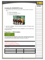
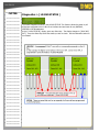
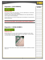
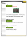
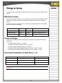
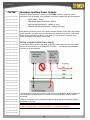
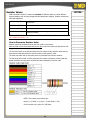
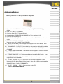
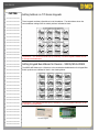
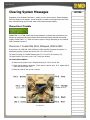
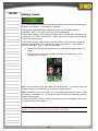
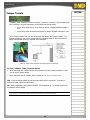
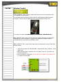
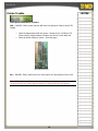
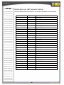
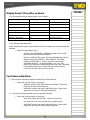
Training Institute
Troubleshooting Guide
3/03
Introduction.....................................................................................................................................1
About this Guide .................................................................................................................................1
The Art of Troubleshooting ..................................................................................................................1
Recommended Troubleshooting Tools ..................................................................................................2
Digital Multi-meter .................................................................................................................................................................. 2
Built-in Tools....................................................................................................................................2
Onboard Diagnostics ...........................................................................................................................2
Accessing the DIAGNOSTICS menu ......................................................................................................3
Diagnostics > [ TEST LX-BUS ] ............................................................................................................3
-How it Works-........................................................................................................................................................................ 4
Diagnostics > [ ZONE FINDER ] ...........................................................................................................5
Diagnostics > [ ZONE STATE ].............................................................................................................5
Diagnostics > [ LX-BUS STATUS ] ........................................................................................................6
Diagnostics > [ MAC ADDRESS ] ..........................................................................................................7
Diagnostics > [ SERIAL NUMBER ] .......................................................................................................7
Diagnostics > [ CURRENT FLASH ].......................................................................................................8
Diagnostics > [ STOP ]........................................................................................................................8
Diagnostics > [ SEND TEST MSG ] .......................................................................................................8
Things to Know ................................................................................................................................9
DMP Feature Codes.............................................................................................................................9
Common Voltages ...............................................................................................................................9
Operational Parameters for Panel Zones 1 – 8*.....................................................................................9
Maximum Auxiliary Power Outputs ..................................................................................................... 10
Wiring a Supplemental Power Supply ..................................................................................................................................... 10
Resistor Values ................................................................................................................................. 11
Output Information ........................................................................................................................... 12
3/03
Voltage Outputs 3 – 10 ..................................................................................................................... 12
Annunciator Outputs ......................................................................................................................... 12
Addressing Devices ........................................................................................................................... 13
Setting Address on 690/790 series keypads.............................................................................................................................13
Setting Address on 770 Series Keypads...................................................................................................................................14
Setting Keypad Bus Address for Devices - XR200/485 & XR500 ................................................................................................14
Clearing System Messages.............................................................................................................15
Phone Line 1 Trouble ........................................................................................................................ 15
Phone Line 1 Trouble XR6, XR10, XRSuper6, XR20 & XR40 ......................................................................................................15
Phone Line 1 Trouble- XR200, XR200/485 & XR2400F..............................................................................................................16
4-Wire Bus Trouble ........................................................................................................................... 17
Transmit Fail..................................................................................................................................... 17
Transmit Trouble .............................................................................................................................. 19
System Trouble................................................................................................................................. 19
System Busy ..................................................................................................................................... 20
NON-POLLED ADDRESS..................................................................................................................... 21
Battery Trouble................................................................................................................................. 22
Tamper Trouble ................................................................................................................................ 23
Wireless Trouble ............................................................................................................................... 24
Printer Trouble.................................................................................................................................. 25
Okidata Micro Line 184T Dip Switch Settings ...........................................................................................................................26
Common Issues- ............................................................................................................................27
Can’t Get into Local Programming ...................................................................................................... 27
Panel Won't Arm ............................................................................................................................... 28
Arming Procedure Chart.........................................................................................................................................................30
Display Doesn’t Clear After an Alarm .................................................................................................. 31
Can’t Silence Bell/Siren...................................................................................................................... 31
Panel is Armed, Zones Do Not Trip..................................................................................................... 32
Can’t Disarm..................................................................................................................................... 32
3/03
Introduction
About this Guide
This guide was originally created to assist DMP Technical Service Technicians help DMP dealers troubleshoot
and fix any problems they may have with DMP equipment. We now offer this guide to DMP dealers and
technicians.
This is an initial release of the troubleshooting course and covers System Monitor and other system trouble
messages.
Any text in this guide that is inside a pair of brackets indicates keypad display text.
Example: [ ENTER CODE:- ]
There are TECHNICAL NOTES that provide you with important information about the topic. Technical notes
are indicated by RED text.
The Art of Troubleshooting
Any technician will tell you that troubleshooting a system is “more art than science”, and it's easy to overlook
the obvious. Whatever your problem is, the cause is usually something simple.
Perhaps something was overlooked in programming, or maybe something is physically incorrect, such as a
panel-jumper placed in the wrong position or an unplugged transformer.
When you're troubleshooting at an installation site or on a service-call, your job is to get the equipment
working properly as quickly and as efficiently as possible. Time is ALWAYS a factor.
When working with ANY manufacturer's equipment, the key to troubleshooting is to know what questions to
ask first.
For example, let's say you have a 'dead' keypad. It has no display and does not respond when keys are
pressed.
What's the first thing to check?
•
DC voltage at the keypad harness? (Is the keypad getting power?)
•
DC output on panel terminals 7 & 10? (Is the panel supplying power?)
•
Wire connections at panel terminals 7 & 10? (Is the keypad connected to the panel correctly?)
•
AC input on panel terminals 1 & 2? (Is the panel getting AC power?)
These are all correct troubleshooting steps for a 'dead' keypad. But the order in which these steps are taken
can change, depending on the layout of your system.
If the keypad is in the same room as the panel, it may be easier to check terminals 7 & 10 for DC output first.
If the keypad is 1000' away, you may save yourself a trip back to the panel by checking the keypad's wire
harness for proper DC voltage. It just depends.
1
-NOTES-
Recommended Troubleshooting Tools
_____________
_____________
Digital Multi-meter
_____________
A multi-meter is definitely a must-have tool when troubleshooting an electronic device, such
as an alarm panel.
_____________
_____________
_____________
An inexpensive, basic digital multi-meter that can measure AC voltage, DC voltage, Ohms
( Ω ) and continuity is really all you need for basic troubleshooting.
_____________
_____________
_____________
_____________
_____________
_____________
_____________
_____________
_____________
_____________
_____________
_____________
Digital multi-meter
Analog multi-meter
Analog multi-meters (like the applause-meter on old TV game shows) will work, too, but
may be difficult to read.
Also, always try to keep a spare battery for your multi-meter. When your meter's battery is
low, the meter may not give an accurate reading.
Built-in Tools
_____________
_____________
_____________
Onboard Diagnostics
_____________
_____________
_____________
_____________
_____________
_____________
_____________
_____________
_____________
_____________
_____________
_____________
_____________
Select DMP Command Processors™ have several built-in Diagnostic features that are
accessible from any system keypad and can assist technicians when troubleshooting a
system.
These Diagnostic functions allow you to test the communication integrity of the LX-Bus™,
identify individual zones, and also display the present electrical state of any zone. The
Diagnostics menu options include:
TEST LX-BUS
SEND TEST MESSAGE
ZONE FINDER
MAC ADDRESS (XR500 series only)
ZONE STATE
SERIAL NUMBER (XR500 series only)
LX-BUS
STATUS
CURRENT FLASH (XR500 series only)
_____________
_____________
2
-NOTES_____________
Accessing the DIAGNOSTICS menu
1. Reset the panel using the J16 reset jumper unless it has been less than 30 minutes
since:
_____________
_____________
a) You were in Programming
_____________
b) You were in the Diagnostics menu or
_____________
c) You powered up the panel.
_____________
_____________
_____________
_____________
_____________
_____________
_____________
The J16 reset jumper- XR200 & XR500
2. Enter 2313 + COMMAND. (It’s easy to remember the number ‘2313’ because it spells
DIAG on the keypad.)
The keypad displays [DIAGNOSTICS]. Press the COMMAND key to move forward through
the Diagnostics menu.
_____________
_____________
_____________
_____________
_____________
_____________
Diagnostics > [ TEST LX-BUS ]
_____________
_____________
_____________
The first Diagnostic function displayed is: [TEST LX-BUS]. This Diagnostics function allows
you to test the ability of the Interface Cards (Models 481, 462N, 462P, 462FM, and 472) to
communicate with zone and output expanders connected to the LX-Bus™.
_____________
_____________
_____________
TECH NOTE: The XR500 Command Processor™ series has one built-in LX-Bus™. An
Interface Card is not required unless:
_____________
_____________
a) TWO or more LX-Busses are needed OR
_____________
b) The on-board RS-232 interface is being used
_____________
To continue, press any Select key. Depending on your Command Processor™ model, the
keypad displays:
_____________
Command Processor™ Model
_____________
Keypad displays...
What to do…
_____________
XR500 series
[ LX-BUS:-
Enter the LX-Bus Number (1-5)
_____________
XR200 series
[ LX-BUS: 1 2 ]
Press Select key below 1 or 2
_____________
]
_____________
_____________
_____________
3
-NOTES_____________
_____________
_____________
You've just told the panel which LX-Bus you want to test. The keypad now displays
[ ADDRESS:- ].
To test address ‘00’ on the selected LX-Bus™, simply press COMMAND. To test only a
particular device, enter the 2-digit LX-Bus device address and press COMMAND.
_____________
_____________
_____________
TECH NOTE: Enter only the address to which the zone expander has been set, and here's
why: You are testing the EXPANDERS on the LX-Bus, not the individual zones. Refer to the
example at the end of the following ‘How it Works’ section for more information.
_____________
_____________
_____________
_____________
_____________
_____________
_____________
_____________
During the test, [ TESTING . . . STOP ] displays on the keypad. At any time, you can press
the Select key below STOP to end the test.
During the test, the panel records the number of responses from the device. If all polls are
received back by the panel correctly, the keypad displays [ 0/65535 FAIL ] (read this as
"zero failures out of 65535 polling attempts") when STOP is selected.
Press the Back Arrow key to enter a new device address or press COMMAND to exit TEST
LX-BUS.
_____________
-How it Works-
_____________
When the panel polls the addressed LX-Bus device, the device is recognized as a multi-zone
device. The panel does not poll the remaining zones on the device.
_____________
_____________
The expander internally polls the remaining zones and transmits any status changes to the
panel. This greatly reduces the amount of time it takes the panel to poll all LX-Bus devices.
_____________
_____________
_____________
_____________
TECH NOTE: At the [TESTING . . . STOP] display, the longer you wait before you select
STOP, the more polling attempts the panel is able to make. The number used above
(65535) is the highest possible number of polling attempts.
_____________
_____________
_____________
If one or more polling attempts fail, the keypad displays [ * * * * */65535 FAIL ] with the *
representing the number of failed polling attempts.
_____________
A display of 65535/65535 FAIL indicates a problem with the Interface Card or its LX-Bus
wiring, such as a bad or broken wire, a wire harness not properly connected, or excessive
noise or distance.
_____________
It can also mean that a zone number was entered that did not match a device address.
_____________
Example: You have a four-zone expander on LX-Bus #1 that is address 00.
_____________
The first zone on the expander is Zone 100. When you try to make the panel poll address
01, the panel isn't looking for address 00. The result is 65535/65535 FAIL.
_____________
_____________
_____________
_____________
_____________
_____________
_____________
4
-NOTES-
Diagnostics > [ ZONE FINDER ]
_____________
_____________
_____________
The second Diagnostic function is the Zone Finder.
Press COMMAND to display [ ZONE FINDER ]. This function allows you to identify
individual zones on devices connected to the LX-Bus of an interface card, the panel, or
any zones on the keypad data bus.
To use ZONE FINDER, press any Select key. The display changes to [ FAULT ZONE ].
The next zone on the system that changes from a normal state to an OPEN or SHORT
state is displayed as
[ ZONE NO: * * * ]. This remains in the display until another zone
changes state.
_____________
_____________
_____________
_____________
_____________
_____________
_____________
To continue, press the Back Arrow key.
_____________
Diagnostics > [ ZONE STATE ]
_____________
_____________
_____________
This Diagnostics function allows you to enter any zone number and check its current
electrical state (Normal, Open, or Shorted).
_____________
At the [ ZONE STATE ] display, press any Select key. The display changes to [ ZONE
NUMBER:- ]. Enter in the zone number you want to check and press COMMAND.
_____________
The panel displays the zone name (first ten characters only) and the current electrical
state of the zone as NORML (normal), OPEN, or SHORT. Example: [FRONT DOORNORML].
_____________
_____________
_____________
_____________
When the state of the zone changes, the display also changes to reflect the change.
_____________
The ZONE STATE feature is a much better way to troubleshoot zone problems than the
Zone Status function in the User Menu because the ZONE STATE display remains until you
exit back into the Diagnostics menu.
_____________
_____________
_____________
Zone Parameters Panel Zones 1-8 and Model 711 and 714 expander zones
_____________
_____________
Zone Condition
OPEN
NORMAL
Short
Resistance On Zone
More than 1300 Ohms
600 – 1300 Ohms
Less than 600 Ohms
Voltage On + Terminal
Over 2.0 VDC
1.2 – 2.0 VDC
Under 1.2 VDC
_____________
_____________
_____________
_____________
_____________
_____________
_____________
_____________
_____________
_____________
5
-NOTES-
Diagnostics > [ LX-BUS STATUS ]
_____________
_____________
_____________
_____________
_____________
_____________
_____________
The fourth Diagnostic function is the LX-BUS STATUS. This function allows the panel to poll
all devices connected to the LX-Bus of an interface card and check for any OVERLAP,
MISSING or EXTRA addresses.
At the [ LX-BUS STATUS ] display, press any Select key. The display changes to [ OVLP MIS
EXT ]. Press the Select key below the status you wish to check. See the illustration below for
more detail.
_____________
_____________
_____________
_____________
_____________
_____________
_____________
_____________
_____________
_____________
_____________
_____________
_____________
_____________
_____________
_____________
_____________
_____________
_____________
_____________
_____________
_____________
_____________
_____________
_____________
_____________
_____________
_____________
_____________
6
Diagnostics > [ MAC ADDRESS ]
-NOTES_____________
_____________
(XR500 series only)
_____________
Every node on a network has a MAC address. Think of the MAC address as a ‘hard-coded’
serial number for a piece of network equipment.
_____________
Computers, routers, network printers and the XR500N(E) all have a unique MAC address,
which is used for hardware identification.
_____________
Press any Select key to view the MAC (Media Access Control) address for the panel’s built-in
network communicator.
_____________
_____________
_____________
_____________
TECH NOTE: THE MAC ADDRESS IS NOT THE SAME AS AN IP ADDRESS! IP addresses are
used for network communication. MAC addresses are used for hardware identification.
_____________
_____________
_____________
_____________
_____________
Diagnostics > [ SERIAL NUMBER ]
_____________
_____________
_____________
(XR500 series only)
Press any Select key to view the network communicator’s manufacturing serial number.
The Serial Number is not a ‘hard-coded’ number like the MAC address. It’s just a number
on a sticker under the J6 header on the panel.
_____________
_____________
_____________
_____________
_____________
_____________
_____________
_____________
_____________
_____________
MAC address and Serial No.
Reference this serial number to find network communicator date-of-manufacture, hardware
version, etc.
_____________
_____________
_____________
_____________
_____________
_____________
_____________
_____________
_____________
7
-NOTES-
Diagnostics > [ CURRENT FLASH ]
_____________
_____________
_____________
_____________
(XR500 series only)
The panel has TWO flash-updateable ROM chips. The processor uses only one at a time.
_____________
_____________
_____________
_____________
_____________
_____________
Flash ROM chips 1 and 2
_____________
_____________
_____________
_____________
_____________
When you flash-update a panel, you are actually updating the UNUSED flash ROM. When
the update is completed, the processor ceases operation for 15 seconds. When the panel
restores itself, it begins to use the newly updated flash ROM.
Press any Select key at the [ CURRENT FLASH ] display. The keypad displays [ FLASH ONE ]
or [ FLASH TWO ] to indicate which physical flash-chip the processor is using now.
_____________
_____________
_____________
_____________
Diagnostics > [ STOP ]
_____________
_____________
_____________
Press any Select key at the [ STOP ] display to exit the Diagnostics menu OR press
COMMAND to display…
_____________
_____________
_____________
_____________
Diagnostics > [ SEND TEST MSG ]
_____________
_____________
_____________
_____________
At the [ SEND TEST MSG ] display, press any Select key to send a signal to the receiver
programmed in COMMUNICATIONS > RECEIVER 1.
_____________
Press the Back Arrow key to display [ STOP ].
_____________
_____________
_____________
_____________
_____________
8
Things to Know
-NOTES_____________
The following sections provide some information that is very helpful when troubleshooting a
problem.
_____________
_____________
_____________
DMP Feature Codes
All XR series Command Processors™ use a numeric code to access certain features. Some of
these features include on-board programmer menu, diagnostic menu and the walk-test
function.
To make them easy to remember, these codes have a word-equivalent that can be spelled
out using the keys on the keypad.
_____________
_____________
_____________
_____________
_____________
DMP Feature
Code
Spells
DMP Models
Programmer Menu
6653
P-R-O-G
ALL XR series panels
Diagnostics Menu
2313
D-I-A-G
XR200 and XR500 series only
One-Man Walk Test
8144
W-A-L-K
XR200 and XR500 series only
_____________
_____________
_____________
_____________
_____________
_____________
Common Voltages
These operating voltages are the same across the entire XR series Command Processor™
product-line:
_____________
_____________
•
AC input (terminals 1 and 2) – 17.3 VAC
_____________
•
Charging circuit output (terminals 3 and 4) – 13.9 VDC
_____________
•
Aux. power output (terminals 7 and 10) – 13.8 VDC
•
Panel data receive output YELLOW (terminals 8 and 10) – approx. 4.5 VDC
•
Panel data transmit output GREEN (terminals 9 and 10) – approx. – 3.5 VDC
Operational Parameters for Panel Zones 1 – 8*
_____________
_____________
_____________
_____________
_____________
Zone Condition
Resistance on Zone
Voltage on + Terminal
_____________
OPEN
More than 1300 Ohms
Above 2.0 VDC
_____________
NORMAL
600 – 1300 Ohms
1.2 – 2.0 VDC
_____________
SHORT
Less than 600 Ohms
Below 1.2 VDC
_____________
_____________
* TECH NOTE: Zones 1 – 9 for DMP XR6, XR10, XRSuper6, XR20 and XR40 Command
Processors™.
_____________
_____________
_____________
_____________
_____________
_____________
_____________
9
-NOTES_____________
_____________
Maximum Auxiliary Power Outputs
All DMP Command Processor™ panels provide 12 VDC of auxiliary power for system
accessories, such as keypads, zone expanders, supervision modules and intrusion detectors.
•
XR5FC/XR5SL – 500mA
•
XR6/XRSuper6/XR10/XR20/XR40 – 600mA
_____________
•
XR200/XR2400F/XR200-485 – 1000mA (1 Amp)
_____________
•
XR500/XR500N/XR500E/XR2500F – 1500mA (1.5 Amps)
_____________
_____________
_____________
_____________
_____________
_____________
_____________
_____________
_____________
Each device consumes a portion of the panel’s available auxiliary power. When the auxiliary
power demand is too great, the panel shuts down the auxiliary power circuit. That means
that anything powered by the panel, is now dead. To take some of the load off of the
panel, an auxiliary power supply can be used.
Wiring a Supplemental Power Supply
To take some of the load off of the panel, an auxiliary power supply can be used to power
some or all of the devices on the keypad bus or LX-Bus™. The diagram below illustrates
how this can be accomplished.
_____________
_____________
_____________
_____________
_____________
_____________
_____________
_____________
_____________
_____________
_____________
_____________
_____________
_____________
_____________
_____________
_____________
_____________
_____________
_____________
_____________
The Sensor Reset Output can be used to reset 2-wire smoke detectors (wired to Model 715
zone expanders) by dropping power to the bus for five seconds when a Sensor Reset is
performed.
If that isn't necessary, then the positive voltage may go directly from the power supply to
the devices on the bus.
TECH NOTE: ALWAYS BE SURE THAT THE NEGATIVE SIDE OF THE AUXILIARY POWER
SUPPLY IS CONNECTED TO THE BLACK WIRE OF THE KEYPAD OR LX-BUS!
_____________
_____________
10
Resistor Values
-NOTES-
DMP Command Processor™ panels use resistors of different values to control different
system voltages, such as zone voltages and bell supervision voltages. Resistor values used
with DMP equipment1,000 Ohm (1KΩ)
Panel zones 1-8 *, all Model 711 and 714 zone expanders, all DMP
keypad zones
3,300 Ohm (3.3KΩ)
Panel zones 9 & 10, all Model 715 zone expanders
6,800 Ohm (6.8KΩ)
Model 725 zone expanders
10,000 Ohm (10KΩ)
XR500 Bell Output (terminals 5 & 6), all Model 866 & 867 Bell
Supervision Modules
* TECH NOTE: DMP XR6, XR10, XRSuper6, XR20 and XR40 Command Processors™ use
1KΩ resistor for zones 1 - 9.
_____________
_____________
_____________
_____________
_____________
_____________
_____________
_____________
_____________
_____________
How to Determine Resistor Value
Resistor values can be determined by the color code on the resistor.
_____________
With the Gold or Silver band positioned to the right, look at the other color-bands from left
to right.
_____________
The first color-band on the left determines the first number of the resistor's value and the
second color-band determines the second number of the resistor's value.
_____________
The third color-band tells us how many zeros to put behind the first two numbers.
The last band (either Gold or Silver) represents the resistor's tolerance, meaning that the
actual resistance can vary above or below the value indicated by the color code.
_____________
_____________
_____________
_____________
_____________
_____________
_____________
_____________
_____________
_____________
_____________
_____________
_____________
_____________
_____________
_____________
_____________
NOTE: The resistor shown above has:
_____________
Brown (= 1), Black (= 0), Red (= 2) and Gold(+/- 5%).
_____________
So this resistor has a value of 1,000 Ohms.
_____________
_____________
_____________
_____________
11
-NOTES_____________
_____________
_____________
Output Information
305 Dry Contact Relays
_____________
•
Single pole, Double throw
_____________
•
Rated at 1 Amp @ 30 VDC resistive
_____________
•
May be activated by any of the following:
_____________
•
Zone condition (open or short)
_____________
•
Output schedule
_____________
•
Manually from User Menu
_____________
•
Communication Fail
_____________
•
Armed Area annunciation
_____________
•
Fire Alarm or Fire Trouble
_____________
•
Other system conditions.
_____________
_____________
_____________
_____________
_____________
_____________
_____________
_____________
_____________
_____________
_____________
See XR200 Programming Guide (LT-0196)
Voltage Outputs 3 – 10
Voltage outputs are available on XR200, XR2400F and XR200/485 Command Processor™
only.
•
12 VDC
•
50mA resistive
•
Activated by same conditions as 305 Dry Contact relay outputs
Annunciator Outputs
Available on XRSuper6, XR6/XR10, XR20, XR40, XR500 Command Processors™ and Output
Expander Model 716.
_____________
•
Switch to GROUND when activated
_____________
•
DO NOT provide voltage
_____________
•
50mA resistive
_____________
•
Activated by same conditions as Model 305 Dry Contact Relay and
Voltage outputs
_____________
_____________
_____________
_____________
_____________
Command Processor™ Models
Output Numbers
XRSuper6, XR6/XR10, XR20 & XR40
1–4
XR500
3-6
_____________
_____________
_____________
12
-NOTES_____________
Addressing Devices
_____________
Setting Address on 690/790 series keypads
_____________
_____________
_____________
_____________
_____________
_____________
690 / 790 series keypad
1. Press and hold the COMMAND and Back Arrow keys until [ SET BRIGHTNESS ] appears on
display
2. Enter 3577 (I-N-S-T) + COMMAND
_____________
_____________
_____________
_____________
3. Press key under KPD OPT (Keypad Options)
4. Keypad displays [ CURRENT KEYPAD ADDRESS: xx ] (xx = address 01-16)
5. Press any top row (Select) key
6. Enter desired address. (Do not enter leading zeroes.) Press COMMAND to scroll to next
option.
7. [ KEYPAD MODE: SUP UNSUP ] To choose Supervised or Unsupervised operation, press
select key under SUP or UNSUP. Press COMMAND
8. [ DEFAULT KEYPAD MSG ] Enter message to be displayed on top row of display. Press
COMMAND
9. [ ARM PANIC KEYS: PN EM FI ] Press select keys below each to enable. When enabled,
each will appear as *PN *EM *FI. (report as Zones: PN=19,EM=29, FI=39) Press
COMMAND
10. [ ACTIVATE ZONE 2 SHUNT: NO ] - Used w/ 693,791,793 keypads for Soft Shunt function.
Press COMMAND
_____________
_____________
_____________
_____________
_____________
_____________
_____________
_____________
_____________
_____________
11. [ ACTIVATE ZONE 3 EXIT: NO ] – Also used with above keypads for REX function. Press
COMMAND
_____________
12. [ 4 DIGIT ENTRY CARDS: NO ] – Select YES for Home/Away or other systems that require
4 digit codes. Press COMMAND
_____________
13. [ ALL? NO YES DELAY: 2 ] – This option is for use in an Area Mode system. When
arming, ALL? YES NO is displayed on the keypad. When NO or YES is not selected before
this delay (1 to 9 seconds) expires, the keypad automatically selects YES. Enter zero to
disable this feature. Press the COMMAND key.
_____________
_____________
14. [ KPD OPT
_____________
KPD DIAG
STOP ] – Press select key under STOP
See LT-0291 for more details.
_____________
_____________
_____________
_____________
_____________
_____________
_____________
_____________
_____________
13
-NOTES-
Setting Address on 770 Series Keypads
_____________
_____________
_____________
These keypads use binary dipswitches to set the address. The table below shows the
correct address settings with the switch positions indicated in black…
_____________
_____________
_____________
_____________
_____________
_____________
_____________
_____________
_____________
_____________
_____________
_____________
_____________
_____________
_____________
TECH NOTE: 733 modules and old style (1 EEPROM) 770 series keypads CANNOT be set
to Unsupervised addresses.
Setting Keypad Bus Address for Devices - XR200/485 & XR500
The XR200-485 allows up to 16 devices to be connected and addressed on the Keypad Bus.
Switch positions are indicated in black in the drawing below.
_____________
_____________
_____________
_____________
_____________
_____________
_____________
_____________
_____________
_____________
_____________
_____________
TECH NOTE: 733 Modules and old style (1 EEPROM) 770 series keypads CAN NOT be set
to Unsupervised addresses.
_____________
_____________
_____________
_____________
770 series keypad
Dipswitch location
_____________
_____________
14
Clearing System Messages
-NOTES_____________
Regardless of the Command Processor™ model, here are some common System Messages
that may display on the keypad. A brief description of what the message means and some
basic troubleshooting tips are listed under each system message heading…
_____________
_____________
_____________
Phone Line 1 Trouble
_____________
_____________
_____________
PHONE LINE 1 or 2 TRBL means that the panel detects a problem with the telephone line.
_____________
Because of hardware differences between DMP residential models and DMP commercial
models, PHONE LINE 1 or 2 TRBL can mean a couple of things, depending on the model of
DMP Command Processor™.
_____________
Phone Line 1 Trouble XR6, XR10, XRSuper6, XR20 & XR40
_____________
RJ supervision for DMP XR6, XR10, XRSuper6, XR20 and XR40 Command Processors™ is
achieved by placing a jumper wire across pins 2 & 7 of the RJ-31X.
_____________
The panel is looking for a SHORT between pins 2 & 7 on its' RJ-45 connector (J3).
_____________
The panel looks for this short on pins 2 & 7 every two minutes.
_____________
To correct this condition:
_____________
_____________
_____________
_____________
a) Make sure the jumper wire is installed across pins 2 & 7 of the RJ-31X.
_____________
b) Check the RJ cable for continuity. There may be a broken wire. If so, replace the RJ
cable with DMP Model 356-2.
_____________
c) Make sure that RJ-31X pin-out is correct.
_____________
_____________
_____________
_____________
_____________
_____________
_____________
_____________
_____________
_____________
_____________
_____________
_____________
_____________
RJ-31X pin-out
_____________
_____________
_____________
15
-NOTES_____________
_____________
_____________
Phone Line 1 Trouble- XR200, XR200/485 & XR2400F
The panel is looking for a SHORT between pins 2 & 7 on its' RJ-45 connector (J3), EXCEPT
WHEN a Model 893 or 893-A Dual Phone Line Module is installed on the panel.
If you ARE NOT using a Model 893 or 893-A Dual Phone Line ModuleKnow this:
_____________
_____________
_____________
_____________
_____________
_____________
•
RJ supervision is achieved by placing a jumper wire across pins 2 & 7 of the RJ-31X.
•
The panel is looking for a SHORT between pins 2 & 7 on its' RJ-45 connector (J3).
•
The panel looks for this short on pins 2 & 7 every two minutes.
To correct this condition:
a) Make sure the jumper wire is installed across pins 2 & 7 of the RJ-31X.
_____________
b) Check the RJ cable for continuity. There may be a broken wire. If so, replace the RJ
cable with DMP Model 356-2.
_____________
c) Make sure that the RJ-31X pin-out is correct.
_____________
_____________
If you ARE using a Model 893 or 893-A Dual Phone Line Module-
_____________
Models 893 and 893-A modules monitor telephone line voltage. When the voltage falls
below 3 VDC, the panel generates a PHONE LINE 1 or 2 TRBL. Here are some things to
check:
_____________
_____________
_____________
_____________
_____________
_____________
_____________
_____________
_____________
-Check phone line voltage
a) Set multi-meter to DC voltage and reset the panel using the J16
b) With the panel J3 still connected to RJ-31X, place meter-leads on pins 4 & 5. If properly
wired for line seizure, this should be your incoming dial tone.
c) Check voltage. When the panel is ON-HOOK (not dialing) this voltage should read
somewhere between 45 and 55 VDC.
d) Make the panel go OFF-HOOK (an easy way to do this is to remove and replace the
TAMPER [J4] jumper) and read the phone line voltage again.
_____________
NOTE: If the phone line voltage drops below 3 VDC, the problem lies with the phone line. If
it does not drop below 3 VDC, try BYPASSING THE 893. To do this:
_____________
a) Place a jumper wire across pins 2 & 7 of the RJ-31.
_____________
b) Disconnect the short RJ cable (between panel's J3 to 893's J1) from the panel J3
_____________
c) Unplug RJ cable from 893's MAIN (BACKUP for PH LINE 2 TRBL), plug into panel's J3
_____________
d) Wait up to TWO minutes for PH LINE TRBL to clear
_____________
Does PH LINE TRBL clear?
_____________
•
YES - Replace 893 Module. BE SURE TO POWER DOWN THE PANEL FIRST!
_____________
•
NO - Enter PROGRAMMING and Initialize EVENTS. This should clear the display. Wait
at least TWO minutes after Initializing EVENTS to make sure that the PH LINE TRBL does
not return.
_____________
_____________
_____________
TECH NOTE: Initializing EVENTS erases ALL EVENTS in the Event Buffer.
_____________
_____________
16
4-Wire Bus Trouble
-NOTES_____________
_____________
When the keypad displays 4-WIRE BUS TRBL it means that the panel has a problem
communicating with the keypad bus devices. 4-WIRE BUS TRBL has NOTHING to do with
the LX-Bus™.
_____________
_____________
More specifically, when the panel polls the keypad bus devices, they aren't able to respond.
_____________
4-WIRE BUS TRBL only displays for the following reasons:
_____________
1. All keypad bus devices set to Unsupervised
_____________
* Make sure at least one keypad bus device is set as Supervised.
_____________
2. Multiple keypad bus devices set to same Supervised address
_____________
* Make sure that all keypad bus devices are addressed correctly (ALL devices sharing an
address* MUST be set as Unsupervised)
_____________
3. Low voltage or no voltage on the panel's Yellow (receive) wire (terminal 8)
* Check data voltage (DC) across terminals 8 & 10 AT the panel and AT the device. If the
voltage is low or open, remove the wires from terminals 7 - 10 and earth ground and check
voltage again.
_____________
_____________
_____________
_____________
* If still low or open, reset the panel using the J16 jumper and check the voltage again.
_____________
If voltage is still low or open, remove ALL wiring (except AC power) and check again. This
last step is taken to make sure that transient voltage isn't being fed into the panel from the
field wiring.
_____________
_____________
_____________
TECH NOTE: Multiple UNSUPERVISED devices may share the same address, as long as:
1) ALL devices using the address are set for UNSUPERVISED operation,
2) None of the devices using the address are being used for zone expansion
3) There is sufficient auxiliary power available to operate the devices. Auxiliary power may
be provided by the panel or an auxiliary power supply or both.
_____________
_____________
_____________
_____________
_____________
_____________
Transmit Fail
_____________
_____________
_____________
When the keypad displays [ TRANSMIT FAIL ] it means that the panel made TEN attempts
to communicate with the receiver, but was unsuccessful.
_____________
_____________
After the ten attempts have failed, the panel tries once every hour to send a TRANSMIT
FAIL message to the receiver.
_____________
The keypad only displays [ TRANSMIT FAIL ] when a user disarms the system or when an
unsuccessful SYSTEM TEST has been initiated from the User Menu.
_____________
_____________
_____________
_____________
_____________
_____________
17
-NOTES_____________
_____________
_____________
_____________
_____________
_____________
_____________
_____________
_____________
_____________
TRANSMIT FAIL (CONT’D)
-WHAT TO DO1. Arm the system. Let the Exit Delay timer count all the way down. Disarm the
system.
* If communication to the receiver has been restored (i.e.- the panel successfully
communicated the TRANSMIT FAIL or any other signal), this should clear the display.
2. Try to send a test-signal.
* Enter the User Menu; press the Command key until the display reads SYSTEM TEST?
Press any Select key. Watch the keypad display. When it shows ATTEMPT NO: 1, the
panel dials the 1st Phone Number programmed in RECEIVER 1 PROG of Communication.
3. When the panel successfully communicates to the receiver, the keypad display
changes to [ TRANSMIT OKAY ]. The panel attempts to send this test-signal
up to 10 times.
_____________
* Verify the phone numbers by calling them from a butt-set at the RJ-31 connected to the
panel's J3 connector. Does a receiver answer? Are you sure it isn't a fax machine?
_____________
* If NO- find the correct phone number and program it into the panel.
_____________
* If YES- call central station to verify that it is the correct receiver for the panel's
programmed communication format
_____________
_____________
_____________
_____________
_____________
•
DD = DMP receiver or Surgard MLR2000
•
HST or NET = DMP receiver with iCOM™
•
CID = any receiver that accepts Ademco Contact ID format
•
4-2 = any receiver that accepts Radionics 4-2 format (w/ checksum)
•
M2E = any receiver that accepts Radionics Modem IIe format
_____________
_____________
4. Are the phone numbers in RECEIVER 1 PROG entered correctly?
_____________
* Make sure that the panel is dialing the correct phone number.
_____________
* Make sure that the panel doesn't need to dial a '9' or other digit to get an outside line.
_____________
* Be sure to include any pauses the panel needs...
_____________
•
_____________
Enter a 'P' before the phone number for a three-second pause in the
dialing sequence
•
Enter a 'D' to make the panel wait for dial tone before dialing
_____________
_____________
_____________
_____________
5. Is panel wired for proper line seizure?
* If phone line is shared with house-phones, fax machine or other equipment, proper line
seizure is a MUST. If the panel does not have line seizure and someone or something else
is using the phone line, the panel can't use the line.
_____________
_____________
_____________
_____________
_____________
_____________
_____________
18
-NOTES-
Transmit Trouble
_____________
_____________
When the keypad displays [ TRANSMIT TRBL ] it means that the panel had to make at least
three attempts to communicate to the receiver.
_____________
_____________
The way to clear Transmit Trouble is to get the panel to communicate on the first or second
attempt.
_____________
1. Enter the User Menu. Press the COMMAND key until the keypad displays [ SYSTEM
TEST ]. Wait.
_____________
2. When the keypad displays [ ATTEMPT NO: 1 ], the panel is dialing the number
programmed in COMMUNICATION > RECEIVER 1 PROG. The panel will make up to
TEN attempts.
_____________
_____________
_____________
_____________
When the panel makes a successful communication to the receiver the display reads: [
TRANSMIT OKAY ]. Did the panel communicate on Attempt No. 1 or 2? If the answer is
YES, you are finished.
_____________
If the panel IS communicating to the receiver within two attempts and this condition still
exists, disarm all areas. You will probably see [ TRANSMIT FAIL ].
_____________
If the panel is NOT communicating to the receiver within two attempts:
_____________
1. Check RJ-31X wiring for proper line seizure.
_____________
_____________
_____________
* If phone line is shared with house-phones, fax machine or other
equipment, proper line seizure is a MUST. If the panel does not have line
seizure and someone or something else is using the phone line, the panel
can't use the line.
_____________
_____________
_____________
2. Use a butt-set connected to the panel's RJ-31X to call the receiver phone number
programmed in COMMUNICATION > RECEIVER 1 PROG. Is it a working phone
number? If not, program the panel with the correct phone number.
_____________
3. Send another System Test to the receiver to verify that the communication is
taking place within two attempts.
_____________
_____________
_____________
_____________
System Trouble
_____________
_____________
_____________
Only a few things cause this message to display. Possible causes are…
1. When XR6/XR10/XR20/XR40 panels are connected to Remote Link for
upload/download, after 2 minutes the SYSTEM TROUBLE will display at the keypads
until the remote session is complete.
2. Low or no (open) voltage on the Green wire of the keypad bus (bad TTL driver)
3. Reset jumper still on J16.
_____________
_____________
_____________
_____________
_____________
4. Processor failure
_____________
_____________
_____________
_____________
19
-NOTES-
System Busy
_____________
_____________
_____________
_____________
_____________
_____________
_____________
_____________
_____________
_____________
_____________
[ SYSTEM BUSY ] can mean that the panel is busy with other communication.
What to do: Reset the panel. Did the display clear?
If not, [ SYSTEM BUSY ] can also mean that the panel's micro-processor is 'locked-up'.
A few things to check:
* Make sure J16 is not shorted
* Make sure Green wire (terminal 9) is not shorted to Ground or any other wire.
If that doesn't clear the display, try this:
STEP 1: Check DC voltage across terminals 8 & 10. Check DC voltage across terminals 9 & 10.
If both measure at 5 VDC, reset the panel (J16) and check the voltages again.
_____________
_____________
_____________
STEP 2: If both voltages still measure at 5 VDC, remove panel ground and remove all wiring
from terminals 7, 8, 9 & 10.
_____________
_____________
STEP 3: Reset the panel (J16). Check data voltages.
_____________
_____________
_____________
•
If both voltages still measure at 5 VDC, replace the panel.
•
If voltages are correct now, begin replacing terminal 7, 8 9 & 10 wiring.
BE SURE TO CHECK DATA VOLTAGES AFTER EACH WIRE IS REPLACED.
_____________
_____________
_____________
By checking the voltages in this manner, you should be able to see when the voltage problem
occurs. When it does, the wire you just replaced is most likely to be the cause of the problem.
_____________
_____________
_____________
_____________
_____________
_____________
_____________
_____________
_____________
_____________
_____________
_____________
_____________
_____________
20
-NOTES-
NON-POLLED ADDRESS
_____________
_____________
When the keypad displays [ NON POLLED ADDR ] it means that this keypad SEES the panel
polling OTHER devices on the keypad bus, but the DEVICE SETUP programming in the panel
has this address set to NONE.
To correct this condition:
If only one keypad is connected to the system and the address is set to something other
than ADDRESS 1, this is almost sure to be the problem.
•
Set the keypad's address to 1 and exit Installer Options. You should be up and
running now.
If there are multiple devices on the keypad bus:
1. Check the keypad's address in the Installer Options. Is it correct?
* If not, change it. Exit Installer Options. Does the keypad work now? If not...
_____________
_____________
_____________
_____________
_____________
_____________
_____________
_____________
_____________
_____________
2. Enter PROGramming from a keypad that IS working correctly- check DEVICE SETUP
programming
_____________
* Be sure that the address is set to STD (set to FIRE for Model 630F keypads)
and exit PROGramming. Now go check the keypad in question. It should work correctly
now.
_____________
_____________
_____________
_____________
_____________
_____________
_____________
_____________
_____________
_____________
_____________
_____________
_____________
_____________
_____________
_____________
_____________
_____________
_____________
_____________
_____________
_____________
_____________
21
-NOTES-
Battery Trouble
_____________
_____________
_____________
_____________
_____________
_____________
_____________
_____________
_____________
_____________
_____________
_____________
_____________
_____________
In a normal condition, the panel tests the backup battery every 3 minutes by performing a
load-test on the battery. This test lasts for 5 seconds.
If the battery voltage falls below 11.9 VDC during this test, the panel generates a
[ BATTERY -TRBL ]. This signal is also sent to the central station
In the trouble condition, panel re-tests the battery every 2 minutes. When the battery’s DC
voltage rises to 12.6 VDC, the [ BATTERY -TRBL ] clears from the display and the restoral
is sent to the central station.
If the battery has been replaced and the trouble condition is still present, try getting into
and out of Programming. This re-starts the 3-minute load-test timer. This usually will
clear the [ BATTERY -TRBL ]. If not, try these steps:
1. Remove the AC wiring from terminals 1 & 2, so that only the battery powers the
panel.
2. Set your meter to DC voltage and place the leads on terminals 3 & 4. Is the
voltage above 11.9 VDC?
_____________
_____________
_____________
_____________
_____________
_____________
_____________
_____________
_____________
_____________
_____________
_____________
_____________
_____________
_____________
Battery Terminals 3 & 4
NO – Then the panel sees the new battery in a trouble condition. You can wait for the new
battery to charge to 12.6 VDC OR you can check the charging circuit…
YES – Replace AC wiring on terminals 1 & 2, remove battery leads from the battery. Check
DC voltage on terminals 3 & 4. You should see about 13.8 VDC (14.2 VDC max.) when the
battery is disconnected.
If you see less than 13.8 VDC, the panel’s charging circuit may be damaged, in which case
the panel will have to be replaced.
_____________
_____________
_____________
TECH NOTE: Any time the battery voltage falls below 10.2 VDC, the panel disconnects the
battery. This is to prevent deep-discharge damage to the battery.
_____________
_____________
_____________
_____________
22
-NOTES-
Tamper Trouble
_____________
_____________
[ TAMPER –TRBL ] displays when the enclosure is opened or removed or the J4 header goes
open, resulting in a signal transmission to the central monitoring station.
•
If this occurs when one or more areas are armed, a tamper ALARM message is
sent.
•
If this occurs when all areas are disarmed, a tamper TROUBLE message is sent.
The J4 Tamper header is for use with an optional DMP Model 306 Tamper Harness. The
harness connects to one or more tamper switches mounted inside the panel enclosure to
detect unauthorized opening or removal of the enclosure.
_____________
_____________
_____________
_____________
_____________
_____________
_____________
_____________
_____________
_____________
_____________
_____________
_____________
_____________
_____________
XR500 J4 Tamper header and Model 306 Tamper Harness wiring diagram
_____________
_____________
To clear [ TAMPER -TRBL ] from the display:
_____________
•
_____________
•
When the Model 306 Tamper Harness is not installed, a jumper should be placed on both
pins of the J4 Tamper header.
When the Model 306 IS installed- place a jumper on J4. Does the display clear?
_____________
_____________
_____________
YES - Close the tamper switch(es) and check the Model 306 for continuity. If harness or
switches are bad, replace the Model 306.
NO - Enter Programming and Initialize EVENTS. Exit Programming. The trouble should now
be cleared from the display.
_____________
_____________
_____________
_____________
TECH NOTE: Initializing EVENTS erases ALL EVENTS in the Event Buffer.
_____________
_____________
_____________
_____________
_____________
_____________
_____________
_____________
23
-NOTES-
Wireless Trouble
_____________
_____________
_____________
_____________
_____________
When [ WIRELESS -TRBL ] displays, it means that the panel has lost communication with
the FA400-DMP wireless receiver.
This message should only display on XR200, XR2400F, XR200/485 and XR500 Command
Processors™ that are using the DMP Model 472 Inovonics 900 MHz Interface Card.
_____________
_____________
_____________
_____________
_____________
_____________
_____________
_____________
_____________
_____________
_____________
_____________
_____________
_____________
To correct this condition: IS A DMP MODEL 472 INTERFACE CARD INSTALLED?
NO- [ WIRELESS -TRBL ] means that the panel has a LX-Bus™ zone that is programmed as
WIRELESS YES in Zone Information, in which case the WIRELESS TROUBLE should be
accompanied by the zone showing as MISSING or FAULT.
YES- [ WIRELESS -TRBL ] means that the panel has lost communication with the FA400-DMP
wireless receiver.
_____________
_____________
_____________
_____________
_____________
_____________
•
Check wiring between 472 and FA400-DMP. Should be Red, Green, and Black. Yellow
is NOT used.
• Make sure that receiver is plugged into the ‘A’ header on the 472. (‘B’ header is for
hard-wired expansion.)
• Press reset button on FA400-DMP. Are any LED’s on the FA400 lit up or flashing? If
not, replace the FA400-DMP.
_____________
_____________
_____________
_____________
_____________
_____________
_____________
_____________
_____________
_____________
_____________
24
Printer Trouble
-NOTES_____________
_____________
Is the panel connected to a printer?
_____________
YES - [ PRINTER -TRBL ] means that the 462P card isn’t getting the Clear to Send (CTS)
voltage.
_____________
•
Check RJ-cable between 462P and printer. Should see 5 to 15 VDC for CTS
(Clear to Send) voltage between the cable's pins 6 and 7 at the 462P end.
•
Check dip-switch settings on printer. (See next page.)
_____________
_____________
_____________
_____________
_____________
_____________
_____________
_____________
_____________
_____________
_____________
_____________
_____________
_____________
Model 462P Printer Card
_____________
NO - [ PRINTER -TRBL ] means that one or more options in Printer Reports is set to YES.
_____________
_____________
TECH NOTE: While the 462P Printer Interface Card will work with other serial printers, DMP
Technical Services only provide technical support for Okidata Microline 184T printers.
_____________
_____________
_____________
_____________
_____________
_____________
_____________
_____________
_____________
_____________
_____________
_____________
_____________
_____________
_____________
25
-NOTES_____________
Okidata Micro Line 184T Dip Switch Settings
If using an Okidata MicroLine 184T printer, be sure that its’ dipswitches are set as follows:
_____________
_____________
Upper Switch Bank 1
OFF/ON
Function
1
OFF
ODD PARITY
2
ON
EVEN PARITY
3
ON
8 BITS
4
ON
READY/BUSY
5
ON
CICRUIT/MONITOR
6
ON
PRINT MODE
7
OFF
SSD
8
ON
DTR/RTS
1
ON
1200 BAUD
2
ON
1200 BAUD
3
OFF
1200 BAUD
4
OFF
DSR INPUT SIGNAL
5
ON
32 BYTE BUFFER
6
ON
200ms BUSY SIGNAL
7
OFF
DTR SIGNAL
_____________
8
OFF
NOT USED
_____________
Lower Switch Bank 1
_____________
1
ON
ASCII
_____________
2
OFF
ASCII
_____________
3
OFF
ASCII
_____________
4
OFF
11 INCH FORM
_____________
5
ON
11 INCH FORM
_____________
6
ON
AUTO LINE FEED
_____________
7
ON
8 DATA BITS
_____________
8
OFF
ENABLE FRONT PANEL
_____________
_____________
_____________
_____________
_____________
_____________
_____________
_____________
_____________
_____________
_____________
_____________
_____________
_____________
_____________
_____________
_____________
Upper Switch Bank 2
_____________
_____________
_____________
_____________
_____________
_____________
26
Common Issues-
-NOTES_____________
Most DMP panels, regardless of model, operate pretty much the same way.
That means that many of the troubleshooting steps taken to resolve an issue are the same,
no matter which Command Processor™ model you happen to be servicing.
This chapter explains what to do when:
_____________
_____________
_____________
_____________
•
CAN'T GET INTO LOCAL PROGRAMMING
•
THE PANEL WON'T ARM
_____________
•
DISPLAY DOESN'T CLEAR AFTER AN ALARM
_____________
•
CAN'T SILENCE THE BELLS OR SIRENS
_____________
•
ZONES DON'T TRIP
•
CAN'T DISARM
_____________
_____________
Usually, these problems have something to do with the system's Programming or the
authority of the User Code you are using to operate the system.
_____________
_____________
_____________
Can’t Get into Local Programming
_____________
To correct this condition: Reset the panel using the J16. Enter 6-6-5-3 (PROG) +
COMMAND.
After entering 6-6-5-3 (PROG), does the keypad display a message?
TECH NOTE: DO NOT enter COMMAND after 6-6-5-3 is pressed on XR6/XR10/XR20/XR40
panels or on XR200 series panels that are in the HOME/AWAY mode.
YES…
•
[ ENTER CODE:- ] There is a lockout code programmed into panel.
* Enter the Lockout Code + COMMAND. Keypad displays [ PROGRAMMER ].
•
[ ACCESS DENIED ] When programmed with a Lockout Code:
* XR200, XR2400F, XR200/485 and XR500 series panels display this if invalid
Lockout Code is entered.
* XR6/10, XRSuper6, XR20 and XR40 panels display this when the COMMAND key is
pressed after entering 6-6-5-3.
•
•
[ RESET PANEL ] Panel must be reset using J16 before local programming
can be done. Once the panel is reset, a 30-minute window is open for you to
get into Programming.
[ SYSTEM BUSY ] Panel processor is locked. J16 is probably still shorted.
_____________
_____________
_____________
_____________
_____________
_____________
_____________
_____________
_____________
_____________
_____________
_____________
_____________
_____________
* Remove jumper. If J16 is not shorted, put jumper on momentarily and remove.
* If problem persists, remove panel Ground and keypad bus wiring, reset panel and
check data voltages directly on the terminals. If both voltages measure 5 VDC,
replace panel.
_____________
•
_____________
[ MAN NUMBER:- ] Panel may be scrambled.
* If it is still communicating with DMP receiver, enter any number + COMMAND.
Keypad should display [ ONE MOMENT… ] while panel dials the receiver and gets
acknowledgment. Panel then (and only then) allows you into Programming.
_____________
_____________
_____________
_____________
_____________
_____________
27
-NOTES_____________
_____________
_____________
-CAN’T ACCESS LOCAL PROGRAMMING- (CONT’D)
* If panel is NOT communicating, contact DMP Technical Services and use ACCODE to get
into local programming or connect to panel with Remote Link and delete User Code 0.
After entering 6653 (PROG), does keypad display a message?
_____________
NO…
_____________
How many Keypads and/or expanders are there on the keypad bus?
_____________
•
If there is more than one, some of the keypad or expander addresses are
probably set the same. Address the keypads and expanders, and then try
to get into programming.
•
If still having problems, remove all keypads except #1 and try again.
_____________
_____________
_____________
_____________
_____________
_____________
_____________
_____________
_____________
_____________
_____________
_____________
_____________
_____________
_____________
_____________
_____________
_____________
_____________
_____________
Panel Won't Arm
When attempting to arm the system, the keypad immediately returns to the Time Display and
nothing arms. Here's what to check:
1) Are there areas in programming?
If no there are no areas programmed, the panel has nothing to arm.
* Enter Programming and check AREA INFORMATION programming.
* Areas must be assigned a name to become active.
2) Does the User Code have authority to Arm/Disarm the areas?
* Assign areas to code and/or check Profile (XR200/485 and XR500 series only) for
Arm/Disarm authority.
TECH NOTE: To assign areas to other User Codes in the system, YOUR CODE MUST HAVE
AUTHORITY FOR THE AREAS YOU ARE TRYING TO ASSIGN. If not, you must Initialize
codes and use the default code [99 + COMMAND] to assign the areas to the User Codes.
3) What Arming Mode is the panel in?
Most DMP panels offer three different MODES of arming. Each mode provides a slightly
different area configuration.These modes are:
ALL/PERIMETER Mode –
Provides TWO, PRE-DEFINED AREAS of protection-
_____________
Area 1 = PERIMETER - Typically contains exterior door and window contacts and glass-break
detectors.
_____________
Area 2 = INTERIOR - Typically contains interior door contacts and motion detectors.
_____________
TECH NOTE: At arming the keypad displays [ PERIM ALL ].
_____________
Select PERIM to arm only the zones assigned to the Perimeter area.
_____________
Select ALL to arm all zones assigned to the Perimeter AND Interior areas.
_____________
NOTE: This mode is not available with XR200/485 or XR500 series panels.
_____________
_____________
_____________
_____________
28
-PANEL WON’T ARM- (CONT’D)
-NOTES-
HOME/SLEEP/AWAY ModeSimilar to the Perimeter/All mode, but provides THREE PRE-DEFINED AREAS of protectionArea 1 = PERIMETER – Same as All/Perimeter mode.
_____________
_____________
_____________
Area 2 = INTERIOR – Same as All/Perimeter mode.
Area 3 = BEDROOMS – Similar to the Interior area, but may be independently DISARMED
from the Perimeter and Interior areas.
_____________
_____________
TECH NOTE: At arming, the keypad displays [ HOME AWAY ]. When zones are assigned
to the BEDROOMS area, the keypad displays [ HOME SLEEP AWAY ] at arming.
_____________
Select HOME to arm zones assigned to the Perimeter area.
_____________
Select SLEEP to arm zones assigned to the Perimeter AND Interior areas.
_____________
Select AWAY to arm zones assigned to ALL three areas: Perimeter, Interior and Bedrooms.
_____________
NOTE: This mode is not available with XR200/485 or XR500 series panels.
_____________
_____________
_____________
_____________
AREA SYSTEM ModeAllows you to define ALL of the areas of the system.
_____________
Each Area of the system may be assigned a name consisting of up to sixteen alpha-numeric
characters.
_____________
Each Area may also be operated independently of the other areas of the system, have its’
own Armed Output and may follow its’ own set of Schedules.
_____________
TECH NOTE: At arming, the keypad displays [ ARM DISARM ]. Press the Select key
beneath ARM.
_____________
_____________
_____________
Now the keypad displays [ ALL? NO YES ] or [ ENTER CODE:- ], depending on how the
Closing Code option is set.
_____________
Enter your User Code, if necessary. Select YES to arm all areas. If a Closing Code is
required, select YES arms all of the areas that are assigned to the User Code or Profile.
_____________
Select NO and the keypad displays each area's name (top line of LCD display) and the area
number, followed by YES and NO options.
_____________
_____________
_____________
Examples:
LOBBY
AREA: 01
_____________
NO YES
WAREHOUSE
OFFICE
AREA: 02
AREA: 03
NO YES
_____________
NO YES
_____________
_____________
See your Programming Guide for details about the number of Areas available on your
system.
_____________
Different modes require different methods of arming AND panels may also be programmed to
require or to not require a Closing Code.
_____________
Depending on how the Closing Code option is programmed (YES or NO) determines the
system's arming process. See the Arming Procedure chart on the next page for more detail.
_____________
_____________
_____________
_____________
_____________
_____________
29
-NOTES_____________
_____________
_____________
_____________
_____________
_____________
-PANEL WON’T ARM- (CONT’D)
Arming Procedure Chart
Mode
HOME/AWAY
ALL/PERIM
AREA
SYSTEM
_____________
_____________
_____________
_____________
_____________
Mode
HOME/AWAY
ALL/PERIM
_____________
_____________
_____________
_____________
Enter code, choose HOME or AWAY
Enter code, choose ALL or PERIM
Press COMMAND until [ ARM DISARM ] displays. Select
ARM. Panel will prompt [ ENTER CODE ].
YES will arm all areas that the User Code has authority to
arm. NO will scroll through the areas assigned to the User
Code, followed by YES NO.
_____________
_____________
Closing Code = YES
AREA
SYSTEM
Closing Code = NO
Press COMMAND until [ HOME AWAY ] appears. Make
selection.
Press COMMAND until [ PERIM ALL ] appears. Make
selection.
Press COMMAND until [ ARM DISARM ] appears, select ARM.
[ ALL? YES NO ] will appear.
YES will arm all areas. NO scrolls each area programmed for
the partition, followed by YES NO.
_____________
_____________
_____________
_____________
_____________
TECH NOTE: The Closing Code option is programmed in SYSTEM OPTIONS on XRSuper6,
XR6/10, XR20 and XR40 panels.
XR200, XR2400F, XR200/485 and XR500 series panels have this option in AREA
INFORMATION.
_____________
_____________
4) Does keypad respond to any key presses?
_____________
* If not, check keypad bus devices for duplicate addresses
_____________
_____________
5) Is keypad address ‘turned on’ in Menu Display for Arm/Disarm?
_____________
* If not, the keypad never displays the arming prompt. Check Menu Display programming.
_____________
_____________
_____________
_____________
_____________
_____________
_____________
_____________
30
-NOTES-
Display Doesn’t Clear After an Alarm
_____________
1) Is the keypad showing a system trouble or a zone alarm?
Zone Type
Displays for…
Display Clears
_____________
_____________
System Troubles
Steady
When Trouble Restores
Fire Alarm
None
Sensor Reset is performed
_____________
Burglary Alarm
1 Second
At Disarm or after 10 min.
_____________
Supervisory Alarm
Steady
Sensor Reset is performed
_____________
Panic Alarm
None
When Zone Restores
_____________
Emergency Alarm
None
When Zone Restores
_____________
Auxiliary 1 and 2 Alarm
None
When Zone Restores
_____________
_____________
2) Has the panel been disarmed?
_____________
Alarm memory doesn’t clear until the Area that the zone is assigned to has been armed and
disarmed.
_____________
•
Disarm the appropriate area(s).
-
Systems in ALL/PERIMETER or HOME/AWAY mode: Enter a valid
User Code that has Arm/Disarm authority
-
Systems in AREA SYSTEM mode: Press the COMMAND key until the
displays reads [ ARM DISARM ]. Select DISARM. The keypad
displays [ ENTER CODE:- ]. Enter a valid User Code that has
Arm/Disarm authority. The keypad displays [ ALL? NO YES ].
Select YES to disarm ALL areas assigned to the User Code. Select NO
to individually display each area that the User Code can disarm.
Choose YES for each area you wish to disarm.
_____________
_____________
_____________
_____________
_____________
_____________
_____________
_____________
_____________
_____________
Can’t Silence Bell/Siren
_____________
1) Does the User Code being entered have authority for Alarm Silence?
•
Check User Code authorities in User Menu.
-
XRSuper6, XR6/10, XR20, XR40, XR200 and XR2400F: Check User
Code level for Alarm Silence authority.
-
XR200/485 (versions and higher) and XR500 series: Check Profile
assigned to User Code for Alarm Silence authority.
2) Is the User Code being entered during its’ assigned Schedule?
•
Check User Code authorities in User Menu.
_____________
_____________
_____________
_____________
_____________
_____________
_____________
-
XR20, XR40, XR200 and XR2400F: Check User Code level.
_____________
-
User Code levels 1 & 2 only operate during scheduled times.
_____________
-
XR200/485 (versions and higher) and XR500 series: Check Profile
assigned to User Code for Shift Schedule assignment.
_____________
_____________
_____________
_____________
31
-NOTES-
•
_____________
•
_____________
Check Time Display on keypad.
-
Check Schedule times in the User Menu. Are they correct?
3) Does the Bell/Siren activate through Fire Alarm Output?
_____________
•
When the Fire Bell Output activates, a Sensor Reset is required.
-
_____________
_____________
_____________
_____________
_____________
_____________
_____________
_____________
_____________
_____________
_____________
Make sure that User Code has authority to perform a Sensor
Reset.
Panel is Armed, Zones Do Not Trip
1) Are zones programmed in ZONE INFORMATION?
•
_____________
_____________
If system time is incorrect, adjust it in the User Menu.
Use the ZONE STATE option in the Diagnostics Menu. Enter the zone number +
COMMAND. Display shows name and electrical state of zone. If the display
shows [ * UNUSED *- NORML ], then the zone is not programmed or the zone
expander may be incorrectly addressed.
2) Is the area that the zone is assigned to armed?
•
Make sure that the area is armed. Trip the zone again.
•
Make sure that your User Code has Arm/Disarm authority for the area being
armed.
3) Are you tripping the correct zone?
•
_____________
Use the ZONE FINDER option in the Diagnostics menu. At the [ FAULT ZONE ]
display, trip the zone. What zone number appears on the keypad display?
-
Check the zone programming in ZONE INFORMATION.
_____________
_____________
_____________
Can’t Disarm
_____________
1) Does the User Code being entered have authority for Arm/Disarm?
_____________
•
_____________
_____________
_____________
_____________
_____________
Check User Code authorities in User Menu.
-
XRSuper6, XR6/10, XR20, XR40, XR200 and XR2400F: Check User Code
level for Arm/Disarm authority.
-
XR200/485 (versions and higher) and XR500 series: Check Profile
assigned to User Code for Arm/Disarm authority.
2) Is the User Code being entered during its’ assigned Schedule?
•
Check User Code authorities in User Menu.
_____________
-
XR20, XR40, XR200 and XR2400F: Check User Code level.
_____________
-
User Code levels 1 & 2 only operate during scheduled times.
_____________
-
XR200/485 (versions and higher) and XR500 series: Check Profile
assigned to User Code for Shift Schedule assignment.
_____________
_____________
_____________
_____________
•
Check Time Display on keypad.
-
•
If system time is incorrect, adjust it in the User Menu.
Check Schedule times in the User Menu. Are they correct?
_____________
_____________
32
-NOTES_________________________________________________________________________________
_________________________________________________________________________________
_________________________________________________________________________________
_________________________________________________________________________________
_________________________________________________________________________________
_________________________________________________________________________________
_________________________________________________________________________________
_________________________________________________________________________________
_________________________________________________________________________________
_________________________________________________________________________________
_________________________________________________________________________________
_________________________________________________________________________________
_________________________________________________________________________________
_________________________________________________________________________________
_________________________________________________________________________________
_________________________________________________________________________________
_________________________________________________________________________________
_________________________________________________________________________________
_________________________________________________________________________________
_________________________________________________________________________________
_________________________________________________________________________________
_________________________________________________________________________________
_________________________________________________________________________________
_________________________________________________________________________________
_________________________________________________________________________________
_________________________________________________________________________________
_________________________________________________________________________________
_________________________________________________________________________________
_________________________________________________________________________________
_________________________________________________________________________________
LT-0788 © Digital Monitoring Products, Inc.
33