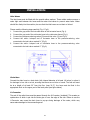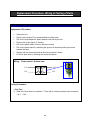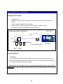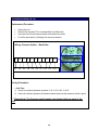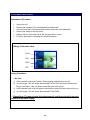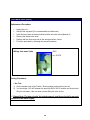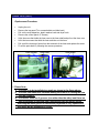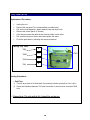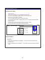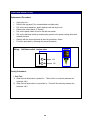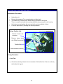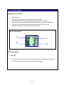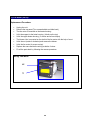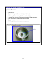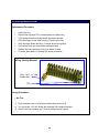
1
BRAND:Majestic
SERVICE MANUAL
LAUNDRY PRODUCTS
Combo Washer Dryer
MODELS
Service Manual
For MJ 9050 V - Venting & For MJ 9950 - Ventless
Service Providers / Warranty for Majestic
Appliance Desk
Ph # 1800 490 8018 Fax # 832 201 0854
#
TABLE OF CONTENTS #
• Warranty Information………………………….……….…………………..
3
• Safe Servicing Practices………………………………………………………
4
• Installation ………………………………………………..………………………..
5
• Important Pre Service Instructions……………………..……………..
6
• Diagnosis & Technical Troubleshooting……………………………..
7
• Replacement Procedure, Wiring & Testing of parts…………..
12
• Quick Check………………………………………………..………………………..
29
• Contact Information…………………………………..………………………..
30
2
WARRANTY INFORMATION
FULL ONE-YEAR WARRANTY
Equator Advanced Appliances undertakes to the
consumer-owner to repair or, at Equator Advanced
Appliances’ option, to replace any part of this
product which proves to be defective in
workmanship or material under normal personal,
family or household use, in the U.S.A., for a period
of one year from the date of original purchase.
During this one year, Equator Advanced Appliances
will provide all labor and parts necessary to correct
such defect, free of charge, if the appliance has
been installed and operated in accordance with
Equator Advanced Appliances written instructions
furnished with the appliance. Ready access to the
appliance, for service, is the responsibility of the
consumer-owner.
Geographic Exception: If the product is installed
at a location more than 50 miles from an urban
area (minimum population 25,000), Equator
Advanced Appliances may, at its option, offer a
2-year parts only Warranty, if a service agent
cannot be found. Responsibility for labor, in such
instances will be that of the consumer-owner.
Equator Advanced Appliances will, however provide
free technical assistance for repairs.
WARRANTY SERVICE
This warranty is given by Equator Advanced
Appliances, Equator Plaza, 2801 W Sam Houston
Pkwy N, Houston, Texas 77043-1611. Service under
this warranty must be obtained by the following
steps, in order:
1. Call an Equator Advanced Appliances Authorized
Service Agent (obtain number of nearest one from
your dealer or telephone directory). Under normal
circumstances, service will be provided during
regular business hours (9:00 a.m. to 5:00 p.m.
weekdays).
2. If service cannot be obtained, call the toll-free
line 800-776-3538 for assistance.
GENERAL
Since it is the responsibility of the consumer-owner
to establish the warranty period by verifying the
original purchase date, Equator Advanced
Appliances recommends that a bill of sale, delivery
slip or some other appropriate payment record be
kept for that purpose. This warranty gives you
specific legal rights, and you may also have other
rights which vary from state to state.
EXCLUSIONS
In no event shall Equator Advanced Appliances be
liable for incidental or consequential damages or for
damages resulting from external causes such as abuse,
misuse, incorrect voltage or acts of God.
This warranty does not cover service calls which
do not involve defective workmanship or
materials covered by this warranty. Accordingly,
diagnosis and repair costs for a service call
which does not involve defective workmanship
or materials will be the responsibility of the
consumer-owner.
In addition, the following work is not covered under
warranty and does not constitute warranty work:
• Installation - improper hook-up or leveling
• Maintenance - cleaning of air and/or water filter.
• Damage - replacing broken door handle Most work is
covered. The defining factor is, has the machine
malfunctioned (Equator is responsible) or has the
customer omitted or done something to cause
machine to malfunction (customer is responsible.)
Some states do not allow the exclusion or limitation of
incidental or consequential damages, so the above
limitation or exclusion may not apply to you.
Please Note : The warranty service for Equator
units is provided by Appliance Desk and hence for
service on any Equator units please contact
Appliance Desk.
Contact Warranty At :
APPLIANCE DESK
2801 W Sam Houston Pkwy N, Suite 120,
Houston, TX 77043-1611
Phone:
Fax :
800-490-8018
832-201-0854
E-Mail
Service: [email protected]
Parts: [email protected]
Tech : [email protected]
3
SAFE SERVICING PRACTICES
6. Prior to returning the product to service ensure
that:
• all electric, gas, and water connections are
correctly and securely connected.
• all gas and water connections are tested for
leaks. DO NOT TEST FOR GAS LEAKS WITH A
1. Do not attempt a product repair if you have
FLAME.
any doubts as to your ability to complete it in a • all electrical leads are properly dressed and
safe and satisfactory manner.
secured
away
from
sharp
edges,
high-temperature components and moving
2. Before servicing or moving an appliance:
parts.
• remove fuse.
• all uninsulated electrical terminals, connectors,
• turn off gas supply.
heaters, etc. have adequate spacing from all
• turn off water supply.
metal parts and panels.
• all safety grounds (both internal and external
3. Never interfere with the proper operation of
to the product) are correctly and securely
any safety device.
connected.
• all panels are properly and securely
4. USE ONLY REPLACEMENT PARTS
reassembled.
CATALOGED FOR THIS APPLIANCE.
SUBSTITUTIONS MAY DEFEAT COMPLIANCE
WITH SAFETY STANDARDS SET FOR HOME
CAUTION! When servicing a water-using
APPLIANCES.
appliance in a location where the water supply
has not been in use for an extended time (such
5. GROUNDING: The standard color coding for as vacation) open the hot water faucet at the
safety ground wires is GREEN or GREEN with sink and allow the water to run for several
YELLOW STRIPES. Ground leads are not to be minutes allowing water and accumulated
used as current carrying conductors.
hydrogen gas to escape. Make sure there are no
IT IS EXTREMELY IMPORTANT THAT THE open flames (pilots) or cigarettes near the
SERVICE TECHNICIAN RE-ESTABLISH ALL faucet.
SAFETY GROUNDS PRIOR TO COMPLETION OF
SERVICE. FAILURE TO DO SO WOULD CREATE A
POTENTIAL HAZARD.
To avoid the possibility of personal injury and/or
property damage, it is important that safe
servicing practices be observed. The following
are examples, but without limitation, of such
practices:
A lightning flash symbol, within a triangle. is
intended to alert the user to the presence of
uninsulated “dangerous voltage” within the
product’s enclosure that may be of sufficient
magnitude to constitute a risk of electric shock to
persons.
An exclamation point within a triangle is intended
to alert the user to the presence of important
operating and maintenance (servicing) instructions
in the literature accompanying the appliance.
CAUTION
RISK OF ELECTRIC SHOCK
DO NOT OPEN
CAUTION: TO REDUCE THE RISK OF
ELECTRIC SHOCK DO NOT REMOVE
COVER OR BACK. DO NOT EXPOSE TO
RAIN OR MOISTURE.
NO USER SERVICABLE PARTS INSIDE.
REFER SERVICING TO QUALIFIED SERVICE
PERSONNEL.
WARNING:
TO PREVENT FIRE OR SHOCK HAZARD, DO NOT
EXPOSE THIS PRODUCT TO RAIN OR MOISTURE.
4
INSTALLATION:
Inlet Hoses
The inlet hoses must be fitted with the special rubber washers. These rubber washers ensure a
water tight seal between the hoses and the water inlet valves to prevent water leaks. Water
should flow freely into the machine, be sure that the inlet hoses are not bent or kinked.
Please read the following steps carefully (Fig.1, Fig.2)
1. Connect the gray end of the hot-water hose to the hot-water faucet (Fig.1).
2. Connect the gray end of the cold-water hose to the cold-water faucet (Fig.1).
3. Connect two pressure-reducing valves [2] to each inlet valve [1] (see Fig.2).
4. Connect the white L-shaped end of hot-water hose to the pressure-reducing valve
connected to the inlet valve marked “H” (Fig.2).
5. Connect the white L-shaped end of cold-water hose to the pressure-reducing valve
connected to the inlet valve marked “C” (Fig.2).
Fig 1
Fig 2
Drain Hose
Connect the drain hose to a drain duct (with internal diameter of at least 1.6 inches) or place it
for drainage in to a sink or a tub, ensuring that there are no kinks or bends. The free end must
be at a height of at least 20” from the floor (max 31.5”), the hose must be fixed in the
appropriate hook on the upper part of the back panel (see figure below)
U-Connector
The end of the outlet hose must be passed through the U-Connector (included). This creates an
upside-down U which is put into the drain pipe or over the edge of the sink. Failure to use the
U-Connector may cause the drain hose to pop-up during drainage of the water, which may
cause water damage to the surrounding area.
5
IMPORTANT PRESERVICE INSTRUCTIONS
► It is advisable for anyone to go through the following points before one actually works
on the unit.
•
Shipping bolts: The unit is shipped with 3 shipping bolts and spacers to avoid
any damage to the unit during shipping. Make sure that all the shipping bolts and
the spacers have been removed from the unit.
•
Height of drain hose: The drain hose should be placed in such a way that the
height of the drain hose does not exceed 36” and is not lower than 28” inches
from the bottom of the unit.
•
Water inlets: In this unit two water inlets are required to be connected for hot as
well as for cold water. Make sure that water supply is provided to both the inlets.
In case hot water supply is not available cold water supply should be connected
to the hot water inlet valve.
•
Leveling: The unit must be leveled properly for proper working of the unit.
•
Flooring: The unit should be installed on strong and leveled floor, installation on
carpet or wood increases vibrations. For better working of the unit, the unit should
be installed on a thin carpet and in case of wooden flooring, proper bracings
should be made and the unit should be installed on a sheet of plywood.
Please note: All the above instructions are mentioned in the Owners Manual and if the
unit is found to be malfunctioning due to any of the above points not been taken care of,
the customer will be liable to pay for the complete service call along with the parts. If the
customer is not willing to pay for the service we will be paying for the same but the
customers warranty will be voided then.
6
DIAGNOSIS AND TECHNICAL TROUBLESHOOTING
◊ INSTALLATION ◊
1) Machine vibrating or vibrating noise
a) Shipping bolts not removed: There are 3 shipping bolts which must be removed along
with the 3 spacers.
b) Machine not leveled: Adjust front leveling legs and tighten locknuts.
c) Machine installed on uneven floor: Adjust leveling legs.
d)
e)
Machine installed on wooden floor: Move machine to a more appropriate location or
install underlayment (also refer to Pre service instructions above)
Rubber cap missing from rear foot:: Install new rubber foot.
2) Water leaking from door
a) Door not screwed in properly: Screw door in properly.
b)
c)
Door not aligned: Align door and screw in properly/Replace with new door if required.
Boot/ door gasket leaking: Change boot / door gasket. (Porthole diaphragm)
◊ WASH CYCLE (MJ 9050V & MJ 9950) ◊
1) Unit won't fill
a) No power input: Check that the cord is plugged in, and circuit breaker or fuse is OK. Test
b)
c)
d)
unit power switch.
No water pressure: Check that fill hoses are connected and that the water supply is turned
on, and hoses are not kinked.
Drain outlet below 24" (water siphoning out): Route drain hose through a clamp on the
rear of the machine, at least 24" above the floor.
Door not closed tightly: Close door firmly, so that it latches.
e) Door Switch/ door lock: Set the washer knob to Towels / Sheets position. Switch On the
f)
power. Test for 115V AC across Pin#11 of the pressure switch and terminal#2 on the control
module. If present the door switch is fine, if not present the door switch is defective.(Make
sure that the door is locked properly)
Pressure Switch. (Test with no water in the tub): Switch Off the power. Remove the
connector to the pressure switch and check for continuity between pins 11 & 12, 21 & 22, 31
& 32 on the pressure switch, It should all read zero resistance, if there is any reading then
the pressure switch is bad.
g) Wash Timer: Set the washer knob to Towels / Sheets position. Switch On the power.
Check for 115V AC across the terminals of EVC (Hot water valve) & EVF (Cold water valve),
if 115V is present the timer contacts are good or else defective.
h)
Water inlet valves: If 115V AC is present across a water inlet valve coil and water pressure
7
is present, the machine should fill. If not, the valve is defective.
2) Unit fills, won’t agitate / tumble
a) Belt: Check belt, adjust tension.
b)
c)
d)
Motor Bolts: Check if the motor is bolted properly.
Pressure Switch: Set the washer knob to Towels / Sheets position. Switch on the unit. The
unit should fill in water and stop to fill. After the unit stops filling, test for 115V AC across
Pin#14 of the pressure switch and terminal#2 on the control module. If present the pressure
switch is fine, if not present the pressure switch is defective.
Motor: Remove the motor connector. Set the washer knob to Towels / Sheets position.
Switch on the unit. The unit should fill in water and stop to fill. After the unit stops filling,
check AC voltage between wires M3 & M5 on the motor connector, it should toggle between
115V AC & 16V AC, similar should be observed between M7 & M5, if found as above the
motor is bad or else the wash timer is bad.
e) Wash Timer: Remove the motor connector. Set the washer knob to Towels / Sheets
position. Switch on the unit. The unit Should fill in water and stop to fill. After the unit stops
filling, check AC voltage between wires M3 & M5 on the motor connector, it should toggle
between 115V AC & 15V AC, similar should be observed between M7 & M5, if found as
above the motor is bad or else the timer is bad.
3) Unit won’t drain out water
a) Filter / Coin Trap: Unplug the unit. Remove foreign objects if any from the filter housing and
b)
clean the filter.
Drain hose: Check for kinks or blockage.
c) Drain outlet above 36”: Drain standpipe inlet more than 36" above the floor.
d)
e)
Pump: Set Wash timer knob to Spin (One click away from off) and switch on the power.
Test for 115V AC at the pump connector, if present the pump is bad, if 115V AC is not
present the timer is bad.
Wash Timer: Set Wash timer knob to Spin (One click away from off) and switch on the
power. Test for 115V AC at the pump connector, if present the pump is bad, if 115V AC is
not present the timer is bad.
4) Unit is noisy
a) Unit not leveled: Adjust leveling legs, tighten lock nuts.
b)
c)
Foreign object in tub: Check tub, remove object.
Shock Absorbers: Check that attachment bolts are tight. Press the inner drum downwards
and experience the force to do so, if enough force is required the shocks are good or else
they are bad.
5) Unit Vibrates
a) Shipping bolts not removed: There are 3 shipping bolts which must be removed along
with the 3 spacers.
8
b) Unstable floor: Remove carpeting, move to another location, or install underlayment.
c) Unit not leveled properly: Adjust leveling legs, tighten lock nuts.
d)
Drum not leveled: If vibration persists then open the top cover and see if the drum is
leveled up. If not the position of the springs holding the drum may have to be adjusted or
else replace the springs.
6) Water leaks from detergent drawer
a) Unit not leveled: Adjust leveling legs, tighten lock nuts.
b)
Spinning with water in tub: Not draining. See Won't drain.
7) Timer doesn’t advance
a) Water supply off: Check water pressure at inlet valve connections.
b)
c)
d)
Filling interrupted: See Won't Fill.
Timer Knob: If the timer knob is having some friction with the panel it won’t allow the wash
timer to advance. Pull out the timer knob and run a cycle to check if the timer is advancing.
Wash Timer: Test wash timer motor resistance: 2000 ohms max. Set to different cycle (e.g.
Delicates) & check timer function different cycle (e.g. Delicates). If the timer still does not
advance the timer is bad.
8) Water fill in tub with unit off
a) Water inlet valves leaking: Identify leaking valve. Remove and clean by back flushing to
remove foreign material. Replace valve if cleaning does not correct the problem.
9) Unit overfills
a) Pressure Switch: Unplug unit. With excessive water still in tub, check for continuity
b)
between terminals 31 and 32. Replace pressure switch if test indicates continuity.
Pressure Switch Hose: Drain machine, then replace kinked or leaking pressure switch
hose. There may also have been some blockage in the pressure switch hose or the air trap,
remove the blockage if any.
10) Door won’t open
a) Door lock enabled: Water in tub. See Won't drain.
b)
Door Switch: Unplug the unit and turn wash timer knob to off position. Wait two minutes for
door switch to unlock. Door should open now. If not the door switch latch is mechanically
stuck. Put one hand behind the door switch and push the metallic plate (latch) forward
towards the drum, simultaneously trying to open the door with the other hand. Replace the
door switch.
11) Unit won’t spin in cycles: Pre wash /Heavy / Towels/sheets /Active wear / Easy care
a) Motor: See Testing of motor.
b)
Speed Regulator / Wash Timer: Set the wash timer to the position one click away from the
off position for the Easy care cycle. Check the continuity between terminal#1 on Speed
9
regulator and the wire M1 on the motor connector, if there is no continuity, the wash timer is
bad, check the continuity between terminals 3 & 4 on the speed regulator if there is
continuity then the speed regulator is bad or else the Wash timer is bad.
12) Unit won’t spin in cycles: Normal / Casual / Quick / Delicate / Wool
a) Motor: See Testing of motor.
b)
Speed Regulator / Wash Timer: Set the wash timer to the position one click away from the
off position for the Normal cycle. Check the continuity between terminal#1 on Speed
regulator and the wire M1 on the motor connector, if there is no continuity, the wash timer is
bad, check the continuity between terminals 4 & 5 on the speed regulator if there is
continuity then the speed regulator is bad or else the Wash timer is bad.
13) Unit keeps filling only when the unit is switched on
a) Pressure switch: Unplug the unit. With excessive water still in tub, check for continuity
b)
between terminals 31 and 32. Replace pressure switch if test indicates continuity.
Motor: Remove the motor connector and check if the water is still filling in, if no the motor is
bad.
14) Clothes wet at the end of wash cycle
a) Water in tub: See Won't drain.
b)
Inadequate final spin: See Won't Spin.
◊ DRY CYCLE (MJ 9050 V / MJ 9950) ◊
1) No tumble action
a) No power input: Check that cord is plugged in, and circuit breaker or, if fuse is OK. Test
b)
unit power switch.
Door not closed: Close door firmly, so that it latches tightly.
c) Belt: Check belt and adjust tension.
2) Clothes cold and damp at the end of dry cycle
a) No Heat coming into the drum: Check the Fuse Link according to the instructions in
Appendix A and replace if necessary.
b) Timer not advanced beyond the cool-down period: Set dryer timer for times longer than
c)
d)
e)
f)
15 minutes.
Thermostats open: Check for continuity between the terminals, at room temperature.
Thermal fuse open: Check for continuity.
Heating element: Check resistance: 25 ohms maximum.
Fan Motor / Dry Timer: Set a 30 minutes cycle on the dryer knob keeping the washer
knob on off position. Check for 115V AC across the two terminals of the fan motor, if present
and the fan motor is not operating, the fan motor is bad or else the dryer timer is bad
provided no part on the heater housing is receiving 115V AC.
10
3) Clothes hot and damp at the end of dry cycle
a)
b)
c)
d)
e)
f)
Blocked filter / Coin Trap: Remove, clean, and replace filter.
*No cold water supply: Cold water is required for dryer to function properly.
* Machine not leveled: Condenser water flow disturbed. Level unit and retest.
Blower impeller: Remove and clean. Also check to see if condensing channel is clogged
with lint.
*Condenser water valve inoperative: Test for 115V AC across the valve terminals. If
present, valve may be defective.
*Blower housing to Tub Seals mismatched: Disassemble blower housing from tub.
Ensure that seals are positioned properly & reassemble.
* Applies only to model MJ 9950
4) Long Drying Time
a) High suds detergent: Use Equator detergent, or other low-suds brand.
b)
c)
d)
Excessive detergent: Measure detergent, using 2 tablespoons or 1/8 cup maximum.
Hot and cold water hoses reversed: Connect hoses to the proper inlet valves.
Dryer section malfunction: See #2 and #3 above for tests to perform.
5) Clothes soaking wet at the end of dry cycle
a) Blocked filter / Coin Trap: Remove, clean, and replace filter.
b) Drain hose: Check the height of the drain pump, it should be at 33” from the bottom of the
c)
d)
unit at the max.
Hose from Tub to drain pump: Check for kinks in the hose from tub to drain pump, it may
have been deformed not allowing a free flowing path for the water to the drain pump.
Drain pump: If all the above have been checked and found to be good, the problem may be
with the drain pump not efficient enough to drain out all the water. Check the efficiency of
the drain pump by using a dry cloth and setting the dry timer to 60 minutes and check the
end result, if the dry cloth is wet at the end the pump is bad.
6) Clothes stiff & wrinkled
a) Over-drying: Set dryer timer for a shorter cycle.
b)
c)
High suds detergent: Use Equator detergent, or other low-suds brand.
Excessive detergent: Measure detergent, using 1 tablespoon.*
11
Replacement Procedure, Wiring & Testing of Parts
1) Power Switch (52799)
Replacement Procedure:
▪
▪
▪
▪
▪
▪
Unplug the unit.
Remove the top panel (Two screws behind and slide back)
Pull out the soap dispenser, plastic washer knob and dryer knob.
Remove the control panel. (3 Screws)
Pull out the plastic switch cover for the power switch.
Pull out the power switch by matching the grooves in the panel pushing the switch
towards the back.
▪
▪
Replace with the new switch and do the wiring as before / below.
Fix all the parts back by following the reverse procedure.
Wiring:
Power switch - bottom view
111
1
2
113
3
4
112
114
Testing Procedure:
▪ Cold Test:
1)
When the Power button is pushed in – There will be continuity between the connectors
1 & 3, 2 & 4.
12
2) Door Switch / Door Lock (00750)
Replacement Procedure:
▪
▪
Unplug the unit.
Open the door remove the clamp to the door gasket in the front to access the door
switch.
▪
▪
▪
Unscrew the two screws to the door switch.
Replace with the new door switch and do the wiring as before / below.
Fix all the parts back by following the reverse procedure.
Wiring: Door Switch – Back View
Latch / Slider
4
IPX
5
IP
1
3
MRL
2
Micro Switch
MRN
Testing Procedure:
▪ Cold Test:
1) Push the slider towards the left (referring to the position of the door switch as in the
figure) which will operate the micro switch and check for continuity between terminals 4 & 5.
2) If there is continuity door switch is good.
e Please Note : The terminals 4 & 5 are not marked on the door switch it is just taken for
explanation.
13
3) Pressure Switch (50774)
Replacement Procedure:
▪
▪
▪
▪
Unplug the unit.
Remove the top panel (Two screws behind and slide back)
Unfix the screw to the pressure switch and replace the same.
Fix all the parts back by following the reverse procedure.
Wiring: Pressure Switch – Back View
32
34 31 16 11 14 12
P1
P2
P3
P4
P5
P6
22 24 21
P7
P8
P9
P10
Testing Procedure:
▪ Cold Test:
1)
2)
Check for continuity between terminals 11 & 12, 21 & 22, 31 & 32.
If there is continuity between all the above stated terminals the pressure switch is good.
e Please Note: The Pressure switch need to be checked with no water in the
unit.
14
4) Cold water valve (10820)
Replacement Procedure:
▪
▪
▪
▪
▪
▪
Unplug the unit.
Remove the top panel (Two screws behind and slide back)
Unfix the two screws at the back which hold the cold water valve.(Marked C)
Remove the clamps to the two hoses.
Replace with the new valve and do the wiring as before / below.
Fix all the parts back by following the reverse procedure.
Wiring: Cold water Valve
EVAX
EVA
EVFX
EVF
Testing Procedure:
▪ Hot Test:
1)
2)
3)
4)
Set the washer knob to the Towels / Sheets position and switch on the unit.
You should get 115V AC across the terminals EVFX & EVF and the unit should start
filling in with water, it the unit does not start filling the valve is bad.
Set the washer knob to the off position and the dryer knob to 60 and switch on the unit.
You should get 115V AC across the terminals EVA & EVAX.
e Please Note: The door should be locked properly and there should be enough
pressure to the water supply.
15
5) Hot water valve (00821)
Replacement Procedure:
▪
▪
▪
▪
▪
▪
Unplug the unit.
Remove the top panel (Two screws behind and slide back)
Unfix the two screws at the back which hold the hot water valve.(Marked H)
Remove the clamp to the hose.
Replace with the new valve and do the wiring as before / below.
Fix all the parts back by following the reverse procedure.
EVC
Wiring: Hot water Valve
EVCX
Testing Procedure:
▪ Hot Test:
1)
2)
Set the washer knob to the Towels / Sheets position and switch on the unit.
You should get 115V AC between the terminals EVCX & EVC and the unit should start
filling in with water, it the unit does not start filling the valve is bad.
e Please Note: The door should be locked properly and there should be enough
pressure to the water supply.
16
6) Wash Timer (50819)
Replacement Procedure:
▪
▪
▪
▪
▪
▪
▪
▪
Unplug the unit.
Remove the top panel (Two screws behind and slide back)
Pull out the soap dispenser, plastic washer knob and dryer knob.
Remove the control panel. (3 Screws)
Unfix the screw that holds the timer cam to the timer shaft and pull out the timer cam.
Unfix the two screws that hold the timer and take out the timer.
Pull out all the housing of wires from the terminals of the timer and replace the same.
Fix all the parts back by following the reverse procedure.
Cam follower
Timer Cam
Timer Angle
e Please Note:
1) The timer is to be installed at an angle as shown in the figure above.
2) The timer cam should be installed making sure that it is holding the cam
follower properly.
3) The washer knob has 2 grooves (one wider than the other) and there are
two projections on the timer cam (one thicker than the other) and so
matching the wider groove to the thicker projection is very important or
else there will be mismatch of cycles.
17
7) Dry Timer (50728)
Replacement Procedure:
▪
▪
▪
▪
▪
▪
▪
Unplug the unit.
Remove the top panel (Two screws behind and slide back)
Pull out the soap dispenser, plastic washer knob and dryer knob.
Remove the control panel. (3 Screws)
Unfix the two screws that hold the dry timer and take out the timer.
Pull out all the wires on the dry timer and replace the same.
Fix all the parts back by following the reverse procedure.
Wiring: Dry Timer
TAB
TAB1
TAA1
TAA
b
TAC
b1
a1
a
Testing Procedure:
▪ Cold Test:
1)
2)
Turn the dryer knob to 30 and check for continuity between terminals a & a1, b & b1.
Check the resistance between TAC and a terminals, it should not be more than 2300
ohm.
e Please Note: The side with b & b1 should be on the top.
18
8) Half Load Switch (51799)
Replacement Procedure:
▪
▪
▪
▪
▪
▪
Unplug the unit.
Remove the top panel (Two screws behind and slide back)
Pull out the soap dispenser, plastic washer knob and dryer knob.
Remove the control panel. (3 Screws)
Pull out the plastic switch cover for the half load switch.
Pull out the half load switch by matching the grooves in the panel pushing the switch
towards the back.
▪
▪
Replace with the new switch and do the wiring as before / below.
Fix all the parts back by following the reverse procedure.
Wiring: Half Load switch - bottom view
122
2
124
4
126
6
Testing Procedure:
▪ Cold Test:
1)
2)
When the half load button is not pushed in – There will be continuity between the
terminals 4 & 6.
When the half load button is pushed in – There will be continuity between the terminals
4 & 2.
19
9) Half Heat Switch (50799)
Replacement Procedure:
▪
▪
▪
▪
▪
▪
Unplug the unit.
Remove the top panel (Two screws behind and slide back)
Pull out the soap dispenser, plastic washer knob and dryer knob.
Remove the control panel. (3 Screws)
Pull out the plastic switch cover for the half heat switch.
Pull out the half heat switch by matching the grooves in the panel pushing the switch
towards the back.
▪
▪
Replace with the new switch and do the wiring as before / below.
Fix all the parts back by following the reverse procedure.
Wiring: Half Heat switch - bottom view
4
134
6
136
Testing Procedure:
▪ Cold Test:
1)
2)
When the half heat button is pushed in – There will be no continuity between the
terminals 4 & 6.
When the half heat button is not pushed in – There will be continuity between the
terminals 4 & 6.
20
10) Fusible Link / Wire with fuse (00807)
Replacement Procedure:
▪
▪
▪
▪
▪
▪
Unplug the unit.
Remove the top panel (Two screws behind and slide back)
The fusible link is located on the heater housing as shown in the figure.
There is a small fuse inside the covering held by the clamp crewed on the housing.
Unfix the screw and replace the same and do the wiring as before / below.
Fix all the parts back by following the reverse procedure.
Wiring: Fusible Link
Remove blower fan
connector
Remove clamp screw
with Philip Screw driver
Fusible link
Remove heater connector
Testing Procedure:
▪ Cold Test:
1)
Check the continuity between the two terminals of the fusible link, if there is continuity
the fusible link is good.
21
11) Thermostat (00808)
Replacement Procedure:
▪
▪
▪
▪
▪
▪
Unplug the unit.
Remove the top panel (Two screws behind and slide back)
The fusible link is located on the heater housing as shown in the figure.
There is a small fuse inside the covering held by the clamp crewed on the housing.
Unfix the screw and replace the same and do the wiring as before / below.
Fix all the parts back by following the reverse procedure.
Wiring: Thermostat
FD
FE
FDX
FEX
Testing Procedure:
▪ Cold Test:
1)
Check the continuity between the two terminals with black dots and the two terminals
with the red dots, if there is continuity the thermostat is good.
22
12) Fan Motor (50732)
Replacement Procedure:
▪
▪
▪
▪
▪
▪
▪
▪
▪
▪
Unplug the unit.
Remove the top panel (Two screws behind and slide back)
The fan motor is mounted on the heater housing.
Unfix the support to the hater housing. (4 bolts on the top)
Unfix the upper heater housing. (3 screws and a few clamps)
The blower / fan is mounted on the shaft of the fan motor with the help of a nut
Unfix the nut (rotate it clockwise) and remove the blower.
Unfix the fan motor (4 screws on top).
Replace the same and do the wiring as before / below.
Fix all the parts back by following the reverse procedure.
Wiring: Fan Motor
MV
TF
23
13) Blower / Fan / Impeller Assembly (51733)
Replacement Procedure:
▪
▪
▪
▪
▪
▪
▪
▪
Unplug the unit.
Remove the top panel (Two screws behind and slide back)
Unfix the support to the hater housing. (4 bolts on the top)
Unfix the upper heater housing. (3 screws and a few clamps)
The blower / fan is mounted on the shaft of the fan motor with the help of a nut
Unfix the nut (rotate it clockwise) and remove the blower.
Replace the same.
Fix all the parts back by following the reverse procedure.
Blower / Fan / Impeller assembly
Nut
24
14) Heating Element (00745)
Replacement Procedure:
▪
▪
▪
▪
▪
▪
▪
▪
Unplug the unit.
Remove the top panel (Two screws behind and slide back)
The heating element is located inside the heater housing.
Unfix the support to the hater housing. (4 bolts on the top)
Unfix the upper heater housing. (3 screws and a few clamps)
Unfix the two nuts and remove the heating element.
Replace the same and do the wiring as before / below.
Fix all the parts back by following the reverse procedure.
Wiring: Heating Element
One end of
fusible link
the
RA
Testing Procedure:
▪ Hot Test:
1)
2)
3)
Set the washer knob on off position and the dryer knob on 30.
You should get 115V AC across the terminals of the heating element.
Check if the unit is heating up, if so the heating element is good.
25
15) Speed Regulator (00791)
Replacement Procedure:
▪
▪
▪
▪
▪
▪
▪
Unplug the unit.
Remove the top panel (Two screws behind and slide back)
The speed regulator is located on the right hand side at the back of the unit.
Unfix the housing of the speed regulator. (2 screws at the back)
Slide out the speed regulator and replace the same.
Do the wiring as before / below.
Fix all the parts back by following the reverse procedure.
Wiring: Speed Regulator
RV1
RV2
RVF
RV3
RV4
RV5
RV6
RV7
e Please Note:
1) The wiring should be done as above, if you operate the unit interchanging
a single wire there is a possibility that the speed regulator goes bad
immediately.
26
16) Drain Pump (00776)
Replacement Procedure:
▪
▪
▪
▪
▪
▪
▪
▪
▪
Unplug the unit.
Make sure that there is no water in the unit.
Carefully pull out the kick plate.
Tilt the unit towards the left and carefully lay down the unit on the side.
Unfix the four leveling legs and remove the bottom panel.
Remove the clamps to the two hoses on the drain pump.
Unfix the 4 screws that hold the drain pump to the cabinet and replace the same.
Do the wiring as before / below.
Fix all the parts back by following the reverse procedure.
Wiring: Drain pump
PSL
PSN
Testing Procedure:
▪ Hot Test:
1)
2)
3)
Set the washer knob to a position one click away from the off position and switch on the
unit.
The drain pump should receive 115V AC supply and should start working.
If the drain pump is working it is fine or else the drain pump is bad.
27
17) Main Motor (50751)
Replacement Procedure:
▪
▪
▪
▪
▪
▪
▪
▪
▪
Unplug the unit.
Make sure that there is no water in the unit.
Remove the back panel (3 screws at the back)
Remove the belt.
Tilt the unit towards the left and carefully lay down the unit on the side.
Unfix the four leveling legs and remove the bottom panel.
The motor is supported with 3 bolts, unfix the same and replace the motor.
Do the wiring as before / below.
Fix all the parts back by following the reverse procedure.
Holes for Bolts
Wiring: Main Motor
M4
4
8
M8
M3
3
7
M7
M2
2
6
M6
M1
1
5
M5
Testing Procedure:
▪ Cold Test:
1)
Check the resistance between the following terminals, if the results match near about,
the motor is fine.
Sr. No
Terminals
Resistance
1
1&2
7.8 – 8.6
2
1&6
2.8 – 3.4
3
2&6
10.6 – 12.0
4
3&5
9.5 – 9.8
5
5&7
9.5 – 9.8
6
3&7
13.0 – 13.6
7
4&8
29.4 – 31.0
e Please Note: Adjust the belt tension after replacing the motor.
28
Quick Check
After replacing any part in the unit you can do a quick check to make sure that the unit is
working normal by following the procedure below:
•
Checking Wash cycle - Set the washer knob to the Towels/Sheets position and
press the Power button, the unit will start filling in with water from both the inlet
valves, after a few minutes the unit stops to fill and the drum will start to agitate.
Then press the Power button, advance the knob to the Spin position and press
the power button the unit will pump out the water and begin to spin
simultaneously.
•
Checking Dry cycle – Set the washer knob to the off position (End of the green
marking) and set a drying cycle for 30’. The unit will start heating up and you can
sense hot air in the drum.
e
Please Note: In this unit the door cannot be opened in the washing cycle
unless and until the washer knob comes to the Off position, however the door can
be opened at any time during the drying cycle.
DON'T FORGET WE ARE HERE WHENEVER YOU NEED HELP ....
APPLIANCE DESK # 1800 490 8018 !!!
********
29