1
NCR 7158 Thermal Receipt and
Impact Printer
Release 1.0
Owner's Guide
B005-0000-1112
Issue D
The product described in this book is a licensed product of NCR Corporation.
NCR is a registered trademark of NCR Corporation.
It is the policy of NCR Corporation (NCR) to improve products as new technology, components, software,
and firmware become available. NCR, therefore, reserves the right to change specifications without prior
notice.
All features, functions, and operations described herein may not be marketed by NCR in all parts of the
world. In some instances, photographs are of equipment prototypes. Therefore, before using this document,
consult with your NCR representative or NCR office for information that is applicable and current.
To maintain the quality of our publications, we need your comments on the accuracy, clarity, organization,
and value of this book.
Address correspondence to:
Manager, Information Products
NCR Corporation
2651 Satellite Blvd.
Duluth, GA 30096
Copyright © 2000
By NCR Corporation
Dayton, Ohio U.S.A.
All Rights Reserved
Owner's Guide
Preface
Important Information to the User
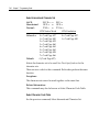
In order to ensure compliance with the Product Safety, FCC and CE
marking requirements, you must use the power supply, power cord,
and interface cable, which were shipped with this product or which
meet the following parameters:
Power Supply
UL Listed (QQGQ), Class 2 power supply with SELV (Secondary Extra
Low Voltage), non-energy hazard output, limited energy source, input
rated 100-240 Vac, 1.5/0.8 A, 50/60 Hz, output rated 24 Vdc, 2.3 A.
Use of this product with a power supply other than the NCR power
supply will require you to test this power supply and NCR printer for
FCC and CE mark certification.
Interface Cable
A shielded (360 degree) interface cable must be used with this product.
The shield must be connected to the frame or earth ground connection
or earth ground reference at EACH end of the cable.
Use of a cable other than described here will require that you test this
cable with the NCR printer and your system for FCC and CE mark
certification.
Power Cord
A UL listed, detachable power cord must be used for this product. For
applications where the power supply module may be mounted on the
floor, a power cord with Type SJT marking must be used. For
applications outside the US, power cords, which meet the particular
country’s certification and application requirements, should be used.
Use of a power cord other than described here may result in a violation
of safety certifications, which are in force in the country of use.
i
ii
Owner's Guide
How to Use This Book
Use this book as a training guide for teaching users how to operate the
printer or as a reference for programming the host computer to
communicate with the printer. In addition, information is also
provided about the character sets and graphics that are available. The
book is divided into chapters that relate to each of these areas.
See the Contents, or Index for detailed listings.
Who Should Use This Book?
This book is intended as a general guide for operators and supervisors
who need to know how to use the printer. It is also intended as a
technical guide for programmers and system integrators who need to
know the technical information about the printer's communication and
the programming commands used by the host computer to control the
functions of the printer.
How to Obtain More Information
For more information about the 7158 printer and to order the following
documentation, please contact your NCR supplier:
•
NCR 7158 Thermal Receipt & Impact Slip Printer Service Guide
(B005-0000-1113) - Service and disassembly procedures (you must
be a trained service representative to service the printer)
Owner's Guide
iii
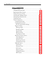
Table of Contents
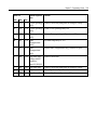
Chapter 1: About the Printer
Introducing the 7158 Printer................................................................ 1-1
Standard Features ................................................................................. 1-2
Connectivity Features .................................................................... 1-2
Advanced Interface Design........................................................... 1-2
Electronics and Firmware.............................................................. 1-2
Thermal Receipt Printer................................................................. 1-3
Impact Slip Printer ......................................................................... 1-4
Options ................................................................................................... 1-5
Connectivity Options ..................................................................... 1-5
Thermal Receipt Printer Options ................................................. 1-5
Impact Slip Printer Options .......................................................... 1-5
Electronics and Firmware Options .............................................. 1-5
Model Identification Key ..................................................................... 1-6
Chapter 2: Setup Guide
Unpacking the Printer .......................................................................... 2-1
Choosing a Location ............................................................................. 2-2
Remove the Packing Restraints........................................................... 2-3
Connecting the Cables.......................................................................... 2-5
Communication Cable ................................................................... 2-5
Cash Drawer Cables....................................................................... 2-6
Power Supply Cable....................................................................... 2-7
Loading Receipt Paper ......................................................................... 2-8
Putting In the Ribbon Cassette.......................................................... 2-10
Testing the Printer............................................................................... 2-11
iv
Owner's Guide
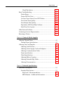
Chapter 3: Using the Printer
Printer Controls..................................................................................... 3-1
Changing the Receipt Paper ................................................................ 3-3
Replacing the Ribbon Cassette............................................................ 3-5
Printing on Forms or Checks............................................................... 3-7
Verifying and Validating Checks...................................................... 3-10
Clearing Check Flip Paper Jams ....................................................... 3-12
Testing the Printer............................................................................... 3-14
Printer Configuration ......................................................................... 3-16
Configuring the Printer ............................................................... 3-17
Communication Interface............................................................ 3-20
RS-232C Serial Interface Settings ........................................... 3-20
Diagnostic Modes ......................................................................... 3-21
Datascope Mode....................................................................... 3-21
Receipt Test Mode.................................................................... 3-22
Slip Test Mode .......................................................................... 3-23
MICR Test Mode ...................................................................... 3-23
Check Flip Test Mode.............................................................. 3-25
Emulation/Software Options ..................................................... 3-26
Printer Emulations ................................................................... 3-26
Printer ID Mode........................................................................ 3-26
Default Lines Per Inch ............................................................. 3-27
Carriage Return Usage ............................................................ 3-27
Hardware Options........................................................................ 3-27
Print Density ............................................................................. 3-27
Maximum Power...................................................................... 3-27
Knife Option ............................................................................. 3-28
Paper Low Sensor..................................................................... 3-28
Printhead Resistance................................................................ 3-28
MICR Option ............................................................................ 3-28
Owner's Guide
v
Check Flip Option .................................................................... 3-28
Basic Troubleshooting ........................................................................ 3-29
Printer Beeps ................................................................................. 3-31
Printer Will Not Print................................................................... 3-32
On-Line, Paper Status, Error LED Flashes................................ 3-33
Poor Forms Print Quality ............................................................ 3-34
Poor Receipt Print Quality .......................................................... 3-34
Slip Station, MICR and Flip Problems....................................... 3-36
Knife Does Not Operate .............................................................. 3-37
Other Serious Problems ..................................................................... 3-38
Contacting a Service Representative ................................................ 3-38
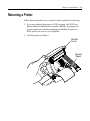
Returning a Printer ............................................................................. 3-39
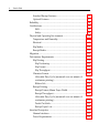
Chapter 4: Printer & Media Supplies
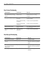
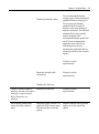
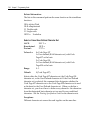
Ordering Thermal Paper...................................................................... 4-1
Thermal Paper Specifications ....................................................... 4-1
Ordering Parts and Supplies ............................................................... 4-2
Ordering Cash Drawers................................................................. 4-2
Ordering Power Supply Cord and Adapters ............................. 4-2
Ordering Communication Cables ................................................ 4-3
Forms Specifications ...................................................................... 4-3
Check Specifications....................................................................... 4-4
Ordering Ribbon Cassettes ........................................................... 4-4
Ordering Extended Slip Tables..................................................... 4-4
Ordering Documentation .............................................................. 4-4
Chapter 5: Technical Specifications
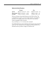
Functional Description ......................................................................... 5-1
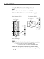
Standard Slip Features................................................................... 5-1
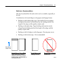
Slip Forms - Recommendations ............................................... 5-3
MICR Reader – Additional Information ................................. 5-5
vi
Owner's Guide
Standard Receipt Features............................................................. 5-5
Optional Features ........................................................................... 5-7
Reliability ............................................................................................... 5-8
Certifications.......................................................................................... 5-9
EMI: .............................................................................................. 5-9
Safety:........................................................................................... 5-9
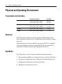
Physical and Operating Environment.............................................. 5-10
Temperature and Humidity........................................................ 5-10
Electrical......................................................................................... 5-10
Slip Media...................................................................................... 5-10
Receipt Media ............................................................................... 5-11
Migration.............................................................................................. 5-12
Performance Requirements ............................................................... 5-12
Slip Printing................................................................................... 5-12
Slip Positioning......................................................................... 5-12
Slip Format ................................................................................ 5-13
Slip Throughput ....................................................................... 5-14
Character Format.......................................................................... 5-15
Allowable Duty Cycle (measured over one minute of
continuous printing) ................................................................ 5-16
Ribbon Life ................................................................................ 5-16
Receipt Printing ............................................................................ 5-17
Receipt Format, 80mm Paper Width ..................................... 5-17
Receipt Throughput:................................................................ 5-21
Allowable Duty Cycle (measured over one minute of
continuous printing) ................................................................ 5-22
Partial Cut Knife....................................................................... 5-22
Receipt Paper Low: .................................................................. 5-22
Interface Description .......................................................................... 5-23
Human Interfaces ......................................................................... 5-23
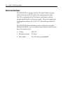
Power Requirements.................................................................... 5-25
Owner's Guide
vii
Electrical Interfaces ...................................................................... 5-26
Switch Settings.............................................................................. 5-27
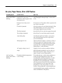
Character Sets................................................................................ 5-27
Code Page 437........................................................................... 5-28
Code Page 850........................................................................... 5-29
Code Page 852........................................................................... 5-30
Code Page 858........................................................................... 5-31
Code Page 860........................................................................... 5-32
Code Page 863........................................................................... 5-33
Code Page 865........................................................................... 5-34
Code Page 866........................................................................... 5-35
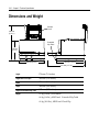
Dimensions and Weight..................................................................... 5-36
Chapter 6: Communication Interface
Communication Overview .................................................................. 6-1
Using DOS to Send Commands ................................................... 6-1
Using BASIC to Send Commands................................................ 6-2
RS-232C Interface .................................................................................. 6-3
Print Speed and Timing................................................................. 6-3
50ms Pause after Each Line ...................................................... 6-4
No Delay after Each Line .......................................................... 6-5
RS-232C Communications............................................................. 6-5
RS-232C Interface Timing ......................................................... 6-5
XON/XOFF Protocol ..................................................................... 6-6
DTR/DSR Protocol......................................................................... 6-7
Connector Pin-outs......................................................................... 6-8
Communication Connectors..................................................... 6-8
Power Connector........................................................................ 6-8
Cash Drawer Connector............................................................ 6-9
viii
Owner's Guide
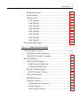
Chapter 7: Programming Guide
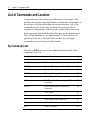
Command Conventions ....................................................................... 7-1
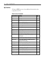
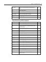
List of Commands and Location......................................................... 7-2
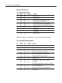
By Command Code ........................................................................ 7-2
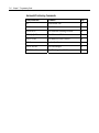
By Function...................................................................................... 7-8
Printer Function Commands .................................................... 7-8
Vertical Positioning and Print Commands............................. 7-9
Horizontal Positioning Commands....................................... 7-10
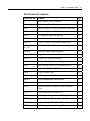
Print Characteristic Commands............................................. 7-11
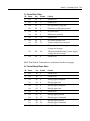
Graphics Commands ............................................................... 7-12
Status Commands .................................................................... 7-12
Barcode Commands................................................................. 7-13
Page Mode Commands ........................................................... 7-14
Macro Commands.................................................................... 7-14
MICR Check Reader Commands........................................... 7-14
Check Flip Commands ............................................................ 7-15
User Data Storage Commands ............................................... 7-15
Flash Download Commands .................................................. 7-16
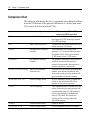
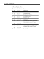
Comparison to 7156 ............................................................................ 7-17
New Features ................................................................................ 7-17
Page Mode on the receipt........................................................ 7-17
Additional Code pages............................................................ 7-17
Additional character attributes .............................................. 7-18
Flip.............................................................................................. 7-18
Additional flexibility when using User-defined
Characters and Logos (Downloadable Bit Image)............... 7-18
Barcodes .................................................................................... 7-18
FLASH Memory Allocation.................................................... 7-18
Higher Baud Rate..................................................................... 7-18
8 Dot High Graphics on Slip................................................... 7-18
Macro Capability...................................................................... 7-19
Owner's Guide
ix
Additional Remote Diagnostics ............................................. 7-19
Comparison Chart ........................................................................ 7-20
Command Descriptions ..................................................................... 7-22
Printer Function Commands ...................................................... 7-22
Clear Printer.............................................................................. 7-22
Exceptions: ................................................................................ 7-23
Close Form ................................................................................ 7-23
Open Form ................................................................................ 7-23
Perform Full Knife Cut ............................................................ 7-24
Perform Partial Knife Cut ....................................................... 7-24
Generate Tone........................................................................... 7-24
Return Home ............................................................................ 7-25
Select Peripheral Device (for Multi-Drop)............................ 7-25
Initialize Printer........................................................................ 7-26
Set Slip Paper Eject Length ..................................................... 7-26
Select Receipt or Slip for Printing; Slip for MICR Read...... 7-27
Select Receipt or Slip for Setting Line Spacing..................... 7-28
Select Paper Sensors to Output Paper End Signals
(Parallel Only)........................................................................... 7-29
Select Sensors to Stop Printing ............................................... 7-30
Enable or Disable Panel Buttons ............................................ 7-30
Enable or Disable Online Switch............................................ 7-31
Set Slip Paper Waiting Time ................................................... 7-31
Generate Pulse to Open Cash Drawer .................................. 7-32
Select or Cancel Parallel Printing Mode on R&J .................. 7-32
Select Slip Station ..................................................................... 7-33
Select Cut Mode and Cut Paper ............................................. 7-34
Select Receipt Station............................................................... 7-35
Print Test Form ......................................................................... 7-35
Vertical Positioning and Print Commands ............................... 7-36
Print and Feed Paper One Line .............................................. 7-36
x
Owner's Guide
Print and Eject Slip................................................................... 7-36
Print and Carriage Return....................................................... 7-37
Feed n Print Lines..................................................................... 7-37
Feed n Dot Rows ...................................................................... 7-38
Add n Extra Dot Rows............................................................. 7-39
Print............................................................................................ 7-40
Set Line Spacing to 1/6 Inch................................................... 7-40
Set Line Spacing ....................................................................... 7-41
Print and Feed Paper ............................................................... 7-42
Print and Reverse Feed Paper ................................................ 7-42
Print and Feed n Lines............................................................. 7-43
Print and Reverse Feed n Lines.............................................. 7-43
Reverse Feed n Lines ............................................................... 7-43
Reverse Feed n Dots................................................................. 7-44
Set Horizontal and Vertical Minimum Motion Units ......... 7-44
Horizontal Positioning Commands ........................................... 7-45
Horizontal Tab.......................................................................... 7-45
Set Column................................................................................ 7-45
Set Absolute Starting Position ................................................ 7-46
Set Horizontal Tabs.................................................................. 7-47
Set Relative Print Position....................................................... 7-48
Select Justification .................................................................... 7-50
Set Left Margin ......................................................................... 7-51
Set Printing Area Width .......................................................... 7-52
Print Characteristic Commands ................................................. 7-53
Select Double-Wide Characters.............................................. 7-53
Select Single-Wide Characters................................................ 7-53
Select 90 Degree Counter-Clockwise Rotated Print ............ 7-54
Select Pitch (Column Width) .................................................. 7-55
Set Character Right-Side Spacing .......................................... 7-56
Select Print Modes.................................................................... 7-57
Owner's Guide
xi
Select or Cancel User-Defined Character Set ....................... 7-58
Define User-Defined Characters ............................................ 7-59
Defining User-Defined Characters for the Slip and
Receipt Station .......................................................................... 7-60
Select or Cancel Underline Mode .......................................... 7-62
Copy Character Set from ROM to RAM ............................... 7-62
Cancel User-Defined Characters............................................ 7-63
Select or Cancel Emphasized Mode ...................................... 7-63
Select Double Strike ................................................................. 7-64
Cancel Double Strike ............................................................... 7-64
Select or Cancel Italic Print ..................................................... 7-65
Select International Character Set .......................................... 7-66
Select Character Code Table ................................................... 7-66
Select or Cancel Unidirectional Printing Mode ................... 7-67
Select or Cancel 90 Degrees Clockwise Rotated Print......... 7-67
Select or Cancel Upside Down Printing Mode .................... 7-68
Select Character Size ................................................................ 7-69
Select or Cancel White/Black Reverse Print Mode ............. 7-71
Select Superscript or Subscript Modes.................................. 7-72
Summary of Rotated Printing ................................................ 7-73
Graphics Commands ................................................................... 7-74
Download BMP Logo .............................................................. 7-74
Select Bit Image Mode ............................................................. 7-75
Select Double-Density Graphics ............................................ 7-78
Select the Current Logo (Downloaded Bit Image) .............. 7-79
Define Downloaded Bit Image............................................... 7-81
Print Downloaded Bit Image.................................................. 7-83
Convert 6 Dots/mm Bitmap to 8 Dots/mm Bitmap........... 7-84
Status Commands......................................................................... 7-85
Status Command Introduction............................................... 7-85
Batch Mode ............................................................................... 7-86
xii
Owner's Guide
Transmit Peripheral Device Status ........................................ 7-86
Request Alternate Status (Parallel Only) .............................. 7-87
Transmit Printer Status ........................................................... 7-88
Transmit Printer ID.................................................................. 7-89
Transmit Printer ID, Remote Diagnostics Extension .......... 7-91
Transmit Status......................................................................... 7-96
Recognizing Data from the Printer........................................ 7-99
Real Time Commands ........................................................... 7-100
Preferred Implementation..................................................... 7-100
Alternate Implementation..................................................... 7-101
Rules for Using Real Time Commands............................... 7-101
Moving Data Through the Buffer ........................................ 7-102
Real Time Status Transmission ............................................ 7-103
Real Time Request to Printer................................................ 7-107
Real Time Printer Status Transmission ............................... 7-109
Auto Status Back .................................................................... 7-110
Select or Cancel Automatic Status Back.............................. 7-110
Bar Code Commands ................................................................. 7-114
Select Printing Position for HRI Characters ....................... 7-114
Select Pitch for HRI Characters ............................................ 7-115
Select Bar Code Height.......................................................... 7-115
Print Bar Code ........................................................................ 7-115
Select Bar Code Width........................................................... 7-119
Page Mode Commands.............................................................. 7-120
Print and Return to Standard Mode .................................... 7-120
Cancel Print Data in Page Mode .......................................... 7-121
Print Data in Page Mode ....................................................... 7-121
Select Page Mode.................................................................... 7-122
Select Standard Mode ............................................................ 7-123
Select Print Direction in Page Mode.................................... 7-124
Set Printing Area in Page Mode........................................... 7-125
Owner's Guide
xiii
Set Absolute Vertical Print Position in Page Mode ........... 7-127
Set Relative Vertical Print Position in Page Mode............. 7-128
Macro Commands ...................................................................... 7-129
Start or End Macro Definition .............................................. 7-129
Execute Macro ........................................................................ 7-130
MICR Commands....................................................................... 7-131
MICR Reading ........................................................................ 7-131
Read MICR Data and Transmit............................................ 7-131
Reread MICR Data ................................................................. 7-131
MICR Parsing.......................................................................... 7-132
Define Parsing Format, Save in NVRAM ........................... 7-132
Define Parsing Format, Do Not Save Permanently........... 7-132
Parsing Parameter String Options ....................................... 7-133
Sample Parsing Formats........................................................ 7-136
Notes ........................................................................................ 7-139
Check Serial Number............................................................. 7-141
Exception Table Entry Format.............................................. 7-144
Maintaining the Exception Table ......................................... 7-145
Check Flip Command ................................................................ 7-146
Check Flip Command............................................................ 7-146
User Data Storage Commands ................................................. 7-146
Write to User Data Storage ................................................... 7-146
Read from User Data Storage ............................................... 7-147
Read from Non-Volatile Memory........................................ 7-147
Write to Non-Volatile Memory (NVRAM)......................... 7-147
Select Memory Type (SRAM/Flash) Where to Save
Logos or User-Defined Fonts................................................ 7-148
Flash Allocation...................................................................... 7-149
Erase User Flash Sector ......................................................... 7-150
Flash Download Commands .................................................... 7-151
Switch to Flash Download Mode......................................... 7-151
xiv
Owner's Guide
Request Printer ID.................................................................. 7-152
Return Segment Number Status of Flash Memory ........... 7-152
Select Flash Memory Sector to Download.......................... 7-153
Get Firmware CRC................................................................. 7-153
Return Microprocessor CRC................................................. 7-154
Erase the Flash Memory........................................................ 7-154
Return Main Program Flash CRC ........................................ 7-154
Erase Selected Flash Sector ................................................... 7-155
Download to Active Flash Sector......................................... 7-156
Reboot the Printer .................................................................. 7-157
Chapter 8: Universal Serial Bus
About the Universal Serial Bus ........................................................... 8-1
Advantages of USB connections................................................... 8-1
Advantages of the NCR USB Solution ........................................ 8-2
Checking for USB Support on the Host Computer .......................... 8-3
Host Configuration ........................................................................ 8-3
Windows NT:.............................................................................. 8-3
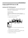
Configuring NCR POS Printers for USB............................................ 8-5
Installing the NCR 7158 USB Upgrade Kit ................................. 8-5
To update the firmware:............................................................ 8-5
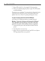
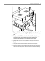
To remove the Options Board and install the USB Board: ... 8-6
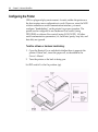
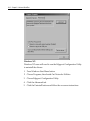
Configuring the Printer ................................................................. 8-8
To define software or hardware handshaking:...................... 8-8
Installing the USB Printer Drivers .................................................... 8-12
Load from NCR LPIN D370-1111-0100................................. 8-12
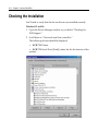
Installing the Drivers ................................................................... 8-12
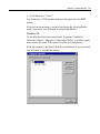
Checking the Installation ................................................................... 8-14
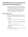
Configuring Serial Port Number Assignments .............................. 8-16
Running the Edgeport Utility ..................................................... 8-16
Serial Port Configuration Methods ............................................ 8-17
Owner's Guide
xv
Uninstalling the Drivers .............................................................. 8-17
Troubleshooting .................................................................................. 8-19
Frequently Asked Questions ............................................................. 8-20
USB Printer Performance Under Windows 95 ......................... 8-20
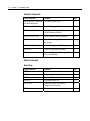
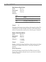
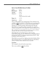
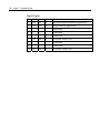
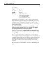
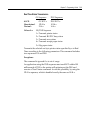
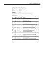
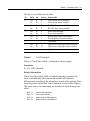
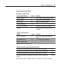
Revision Record
Issue
Date
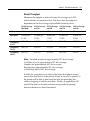
Remarks
A
Apr 99
First issue
B
June 99
Minor Updates
C
June 00
Updates
D
Jan 03
Updates
xvi
Owner's Guide
Radio Frequency Interference Statements
Federal Communications Commission (FCC)
Information to User
This equipment has been tested and found to comply with the limits for a Class A
digital device, pursuant to Part 15 of FCC Rules. These limits are designed to provide
reasonable protection against harmful interference when the equipment is operated in
a commercial environment. This equipment generates, uses, and can radiate radio
frequency energy and, if not installed and used in accordance with the instruction
manual, may cause harmful interference to radio communications. Operation of this
equipment in a residential area is likely to cause interference in which case the user
will be required to correct the interference at his own expense.
NCR is not responsible for any radio or television interference caused by unauthorized
modification of this equipment or the substitution or attachment of connecting cables
and equipment other than those specified by NCR. The correction of interference
caused by such unauthorized modification, substitution or attachment will be the
responsibility of the user. The user is cautioned that changes or modifications not
expressly approved by NCR may void the user’s authority to operate the equipment.
Canadian Department of Communications
This digital apparatus does not exceed the Class A limits for radio noise emissions
from digital apparatus set out in the Radio Interference Regulations of the Canadian
Department of Communications.
Le présent appareil numérique n’émet pas de bruits radioélectriques dépassant les
limites applicables aux appareils numériques de la classe A prescrites dans le
Règlement sur le brouillage radioélectriques édicté par le ministrère des
Communications du Canada.
Voluntary Control Council For Interference (VCCI)
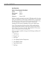
Chapter 1:
About the Printer
Introducing the 7158 Printer
The 7158 is an extremely fast, quiet, and reliable point-of-sale printer. It
consists of two specialized printers in one compact package: a thermal
printer on top that prints receipts, and an impact slip printer in front to
print on forms and checks that you insert. The thermal printer is
optimized for ease-of-use in busy environments. There is no ribbon or
ink cartridge to change, and you load the paper by simply dropping in
a new roll. The impact printer provides the power and flexibility
necessary to print on checks or multi-part forms up to five plies, in a
wide variety of sizes and orientations.
The 7158 easily fits in anywhere. It connects to any host computer that
uses the standard RS-232C interface. Other interfaces are also available.
The printer’s standard command set allows it to work with software
written for NCR, or other ESC/POS™ compliant printers. A variety of
sensors enable the printer to communicate its status, and the printer’s
journal is kept electronically by the host computer.
Several state-of-the-art check-handling options are also available. The
Magnetic Ink Character Recognition (MICR) option enables the printer
to read the special codes printed on checks and send this information
to the host computer to verify the check. The Check Flip option saves
transaction time by making check handling a one-step process—after
reading the front of the check and printing on the back, the printer is
able to flip the check over and print on the front of the check.
This section describes the printer’s features and options in more detail.
1-2
Chapter 1: About the Printer
Standard Features
Connectivity Features
Industry standard RS-232C interface for communication with the host
computer; other interfaces are available as options.
•
Cash drawer kickout connector and software support for up to two
cash drawers.
Advanced Interface Design
•
Sensors detect whether any of the covers are open, the paper is low
in the receipt printer, or the paper is positioned properly in the slip
printer.
•
Software-controlled audible tone for various alerts.
•
Online Configuration Menu—the printer guides the user through
its configuration settings by printing instructions and a menu on
receipt paper.
Electronics and Firmware
•
Industry-standard command set makes the printer compatible with
existing software, yet enables new features.
•
Remote diagnostics capability tracks important printer data.
•
512K flash memory with 192K available for multiple logos,
graphics, user-defined character set, and user data storage. The
printer is also available with 1 MB or 2 MB flash memory for
additional user memory.
•
16-bit electronics architecture.
•
Communication rate up to 115,200 baud.
•
Flash download mode lets the user upgrade the printer’s firmware.
Chapter 1: About the Printer
1-3
Thermal Receipt Printer
•
Extremely fast and quiet thermal printhead.
•
No ribbon or ink cartridge to change.
•
Drop-in paper loading.
•
Double high, double wide, bold, inverse, underlined, superscript
and subscrip, italics, scalable and rotated print modes.
•
Resident character sets: Code Pages 437 (US), 850 (Multilingual),
852 (Slavic), 858 (with Euro symbol), 860 (Portuguese), 863 (FrenchCanadian), and 865 (Nordic) and 866 (Cyrillic).
•
Prints standard bar codes: Code 39, UPC-A, UPC-E, JAN8 (EAN),
JAN13 (EAN), Interleaved 2 of 5, Codabar, Code 93, Code 128, and
PDF-417 two-dimensional code. Also prints “ladder” bar codes.
•
Host-selectable 44 or 56 columns on 80 mm wide “POS grade”
thermal paper.
•
8 dots/mm print resolution.
•
Up to 130 mm/second print speed.
•
Optional receipt cutter.
1-4
Chapter 1: About the Printer
Impact Slip Printer
•
Bi-directional impact printhead designed for a very long life.
•
Snap-on ribbon cassette.
•
Prints on forms up to five plies.
•
Horizontal flatbed slip table with an optional extension (which is
standard with the MICR check reader option).
•
Form insertion flexibility: insert forms in front or from the side.
•
Form alignment sensors and LED indicator.
•
Double wide and rotated print modes; a double strike print mode
improves contrast.
•
Software selectable pitch: either standard (13.9 characters per inch,
66 columns) or compressed (17.1 characters per inch, 80 columns).
•
290 lines-per-minute print speed.
•
Optional check handling features (see “Impact Slip Printer
Options” on next page).
Chapter 1: About the Printer
1-5
Options
Connectivity Options
•
RS-232C is supported on all printers. USB is also supported on
some later models.
•
Communications cables are available for RS-232C and USB.
•
Power supplies are available in 55 Watt or 75 Watt versions.
•
3-pin to 6-pin power connection adapter to allow previous version
power supplies (or terminal cables) to be connected to the 7158.
Thermal Receipt Printer Options
•
The optional receipt cutter.
Impact Slip Printer Options
•
The slip table is available in either standard or 2 extended sizes. An
extended slip table is standard with the MICR check reader and flip
options.
•
The Magnetic Ink Character Recognition (MICR) check reader is
built into the slip station. It reads checks that use standard E13B or
CMC7 MICR fonts.
•
Check Flip Option: after reading the MICR line on the front of the
check and printing on the back, the printer is able to flip the check
over and print on the face of the check.
Electronics and Firmware Options
•
1 MB or 2 MB Expanded flash memory is available as factory
configurations.
1-6
Chapter 1: About the Printer
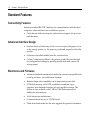
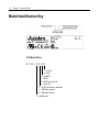
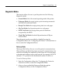
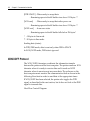
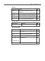
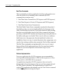
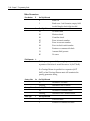
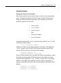
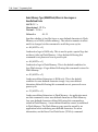
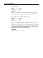
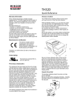
Model Identification Key
A758 Model ID Key
A 7 5 8 - X X X X
1 = no knife
5 = knife
0 = no MICR
1 = MICR
2 = MICR and check flip
5 = check flip
0 = 512K Flash memory (standard)
1 = 1MB Flash memory
2 = 2MB Flash memory
1 = standard color
Chapter 1: About the Printer
1-7
The set of options installed on a particular printer can be determined
by looking at the printer's model number. The printer's model number
appears on a label on the right side of the printer. Four-digit model
numbers are assigned to the various 7158 models based on the
following formula:
•
The first digit indicates the release vintage and color of the printer's
case.
•
The second digit indicates the amount of flash memory installed in
the printer.
•
The third digit indicates whether the printer has the MICR and/or
check flip features.
•
The fourth digit indicates whether the printer has a knife for
cutting receipts.
For example, a printer with model number 7158-1015 has a standard
color case, 512K of flash memory, the MICR feature, and a knife for
cutting receipts.
1-8
Chapter 1: About the Printer
Chapter 2:
Setup Guide
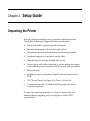
Unpacking the Printer
Save all packing materials in case you need to repack the printer.
Check that the materials shipped with the printer match.
•
Printer enclosed in a plastic bag and foam pack
•
Thermal receipt paper roll (inside receipt bucket)
•
Test printout protecting the printhead (inside receipt bucket)
•
Cardboard support for cantilever (on slip table)
•
Foam restraint for carriage (behind front cover)
•
Power supply with cable connecting to printer and power supply
cord connecting to power outlet (only if ordered with the printer)
•
Ribbon cassette
•
Installation report card (please complete this form and return to
NCR)
•
7158 Thermal Receipt and Impact Slip Printer: Setup Guide
•
Communication cable, if ordered with the printer (from host
computer to printer)
To report any missing materials, or to report a printer that was
damaged during shipping, call your supplier or call an NCR
representative.
2-2
Chapter 2: Setup Guide
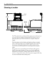
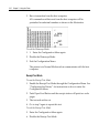
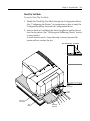
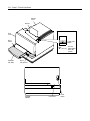
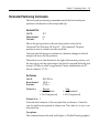
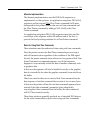
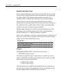
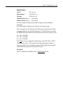
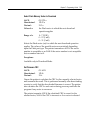
Choosing a Location
Receipt
Cover
280 mm
(11.0 in.)
Extended
Slip Table
178 mm
(7.0 in.)
229 mm (9.0)
264 mm (10.4 in.)
347 mm (13.7 in.)
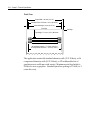
The 7158 printer takes up relatively little counter space and may be set
on or near the host computer. With the RS-232C interface, you can
place the printer up to 50 feet from the host computer and power
supply.
Place the printer on a level surface, and make sure there is enough
room to open the receipt cover to change the paper and to open the
front cover to change the impact printer’s ribbon cassette. Leave
several inches around the printer for connecting and accessing the
cables.
If the printer has an optional Magnetic Ink Character Recognition
(MICR) check reader installed, you may need to make additional
adjustments to the printer’s location. Because devices such as CRT
monitors or large metal surfaces affect the printer's magnetic field, they
can cause intermittent check reading errors.
Chapter 2: Setup Guide
2-3
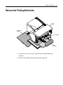
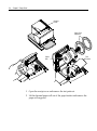
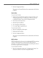
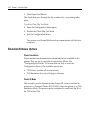
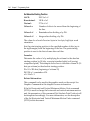
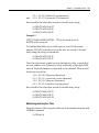
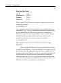
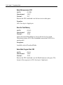
Remove the Packing Restraints
Front
Cover
Cardboard
Support
Carriage
Foam
Restraint
1. Open the front cover, remove the foam restraint holding the
carriage.
2. Remove the cardboard support from the slip path.
2-4
Chapter 2: Setup Guide
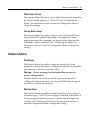
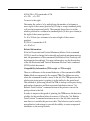
Receipt
Cover
Paper Roll
Supports
Paper
Roll
Test
Printout
1. Open the receipt cover and remove the test printout.
2. Lift the thermal paper roll out of the paper bucket and remove the
paper roll supports.
Chapter 2: Setup Guide
2-5
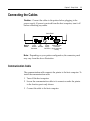
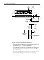
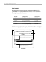
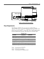
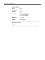
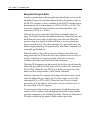
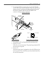
Connecting the Cables
Caution: Connect the cables to the printer before plugging in the
power supply. If power is received from the host computer, turn it off
before connecting any cables.
Strain Relief
Back of
Printer
DIP
Cash
Power
Drawer Switches Supply
Connector
Connector
Communication
Connector
(9-pin connector
shown)
Note: Depending on your printer configuration, the connector panel
may vary from the above illustration.
Communication Cable
The communication cable connects the printer to the host computer. To
install the communication cable:
1. Turn off the host computer.
2. Secure the communication cable to its connector under the printer
in the location previously shown.
3. Connect the cable to the host computer.
2-6
Chapter 2: Setup Guide
Cash Drawer Cables
The cash drawer cable connects the printer to one or two cash drawers.
1. Plug the cable into the cash drawer connector (standard phone jack)
located at the rear of the printer.
Y-Cable
Drawer
Printer
Drawer
Printer Connector
(Standard Phone Jack)
Note:
a. If your system has two cash drawers, attach a Y-cable to the
printer’s cash drawer connector as shown.
b. Leave some slack in the cord to route through the strain relief at a
later time.
Chapter 2: Setup Guide
2-7
Power Supply Cable
Connect the power supply cable last.
1. Plug the power cord into the power supply.
To the
Communications
Connector
Strain
Relief
Power
Supply
or Adapter
Cable
Communications
Cable
Cash Drawer
Cable
Cash Drawer
Cable
2. Route the cash drawer and the power supply cables through the
stain relief as shown.
3. Plug the power cord into the power supply, then plug the power
supply into an outlet. The Green LED on the top cover will light up.
2-8
Chapter 2: Setup Guide
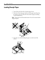
Loading Receipt Paper
1. Tear off the end of the roll so that the edge is loose.
2. Place the roll into the paper bucket with the paper unrolling from
the bottom of the roll, and with a few inches of paper extending
over the cabinet front.
Note: Paper must unroll from the bottom of the roll to insure that the
image will print.
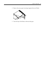
3. Close the cover while holding the paper over the front of the
cabinet.
Chapter 2: Setup Guide
4. Remove the excess paper by tearing it against the tear-off blade.
5. Press the Paper Feed Button to advance the paper.
2-9
2-10
Chapter 2: Setup Guide
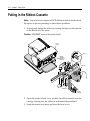
Putting In the Ribbon Cassette
Note: You must use an approved NCR ribbon cassette with the check
flip option to prevent jamming or other ribbon problems.
1. Unwrap and tighten the ribbon by turning the knob on the cassette
in the direction of the arrow.
Caution: DO NOT remove the mylar shield.
Front
Cover
Knob
Ribbon
Cassette
(Shown in
Position)
Cassette
Printhead
Ribbon
Mylar
Shield
2. Open the printer’s front cover, position the ribbon cassette onto the
carriage, making sure the ribbon is underneath the printhead.
3. Snap the cassette into place and close the front cover.
Chapter 2: Setup Guide
2-11
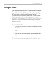
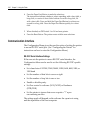
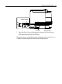
Testing the Printer
The Configuration Menu allows you to set general printer parameters.
The test prints a list of various printer settings and partially cuts the
paper if a knife is installed. The test printouts may vary depending on
the printer model. To change the default settings, enter the
Configuration Menu as instructed on the bottom of the test printout.
The printout may be useful to a service representative if there is a
problem. If something appears to be wrong with the test printout (such
as missing or faded text) additional troubleshooting and diagnostic
guides are available.
1. To run the test, either:
a. Open and close the receipt cover while holding down the Paper
Feed Button,
OR,
b. Press the Paper Feed Button and the Reset Button at the same
time.
2. When the printer begins printing let go of the Paper Feed Button.
2-12
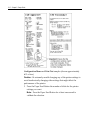
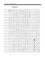
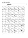
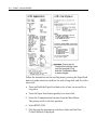
Chapter 2: Setup Guide
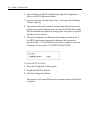
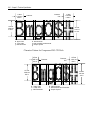
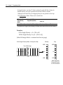
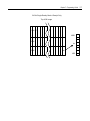
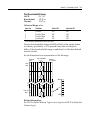
Configuration Menu and Print Test samples (shown approximately
60% of size).
Caution: Be extremely careful changing any of the printer settings to
avoid inadvertently changing other settings that might affect the
performance of the printer.
3. Press the Paper Feed Button the number of clicks for the printer
settings you want.
Note: Press the Paper Feed Button for at least one second to
validate the selection.
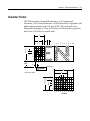
Chapter 3:
Using the Printer
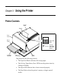
Printer Controls
Receipt
Cover
Receipt
Front
Cover
Slip or
Check
Paper Feed
Button
On-Line,
Paper Status,
Error LED
(Green)
Extended
Slip Table
Slip In
LED (Green)
Reset
Button
The printer has the following controls:
•
The Paper Feed Button advances the receipt paper.
•
The On Line, Paper Status, Error LED shows the printer status by
shining or flashing.
•
The Slip-in LED indicates that a form is inserted properly.
•
The Reset Button clears the printer’s memory or begins special
modes.
3-2
Chapter 3: Using the Printer
The printer also indicates its status when it is first turned on, or after it
has been reset, by beeping. A single beep indicates the printer has
successfully completed its startup routine. But if the printer beeps in a
single, double, or triple pattern at first power on, please call your
service representative.
Chapter 3: Using the Printer
3-3
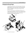
Changing the Receipt Paper
Change the paper when either a colored stripe appears on the receipt
paper or the printer’s On Line, Paper Status, Error LED slowly flashes
(indicating that 5 + 10 feet of paper remains on the roll). Change the
paper as soon as possible to avoid running out of paper part way
through a transaction.
If the On Line, Paper Status, Error LED blinks fast, the paper is out.
Change the paper immediately or data may be lost. The printer will not
operate without paper, but it may continue to accept data into memory
from the host computer. Because the printer cannot print any
transactions, this data in memory may be lost.
Receipt
Cover
To change the receipt paper:
3-4
Chapter 3: Using the Printer
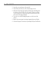
1. Open the cover and remove the used roll.
2. Tear off the end of the new roll so that the edge is loose.
3. Place the roll into the paper bucket with the paper unrolling from
the bottom of the roll, and with a few inches of paper extending
over the cabinet front. Paper must unroll from the bottom of the
roll to insure the image will print.
4. Close the cover while holding the paper over the front of the
cabinet.
5. Remove the excess paper by tearing it against the tear-off blade.
6. Advance the paper if necessary by pressing the Paper Feed Button.
Chapter 3: Using the Printer
3-5
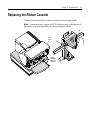
Replacing the Ribbon Cassette
Change the impact printer’s ribbon cassette if it is printing lightly.
Note: You must use an approved NCR ribbon cassette with the check
flip option to prevent jamming or other printing problems.
Tab
Front
Cover
Tab
Ribbon
Cassette
(Shown in
Position)
3-6
Chapter 3: Using the Printer
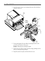
1. Open the printer’s front cover and pinch the tabs of the old ribbon
cassette to remove it.
Front
Cover
Knob
Ribbon
Cassette
(Shown in
Position)
Cassette
Printhead
Ribbon
Mylar
Shield
2. Unwrap and tighten the new ribbon by turning the knob on the
cassette in the direction of the arrow.
Caution: Do not remove the Mylar shield.
3. Position the new ribbon cassette onto the carriage, making sure the
ribbon is underneath the printhead.
4. Snap the cassette into place and close the front cover.
Chapter 3: Using the Printer
3-7
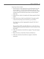
Printing on Forms or Checks
There are several types of transactions that may require the insertion of
a form or check into the printer:
•
Credit card transaction
•
Multiple-part forms such as credit transactions or merchandise
returns
•
Electronic funds transfers
•
Check printing (printing the date, payee, and amount on the check
face)
•
Check endorsement
3-8
Chapter 3: Using the Printer
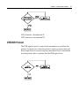
Although the illustration on the following page shows a check being
inserted into the printer, these instructions apply to any type of form.
The 7158 can print on forms up to five parts thick.
2001
19
PAY TO THE
$
ORDER OF
DOLLARS
MEMO
¦
Check Orientation
Green
Slip-in LED
Check
Guide
First Line of
Print Guide
Slip
Table
Extended
Slip Table
Chapter 3: Using the Printer
3-9
To print on a form or check:
1. Insert the form or check (check shown in the illustration) from the
front and place it on the Slip Table with the print side up. If the
form is extra long, you may need to insert it from the side. A slight
resistance may be felt when the form comes in contact with the
Form Stop.
2. Slide the form or check to the right until it aligns against the Check
Guide.
3. Slide a short form or check toward the back of the printer until it
contacts the Form Stop (it won't be able to go any further).
For a long form, position it appropriately using the First Line of
Print Guide.
The green Slip-in LED on the Slip Table turns on when the form or
check is properly inserted (the form has to cover two sensors on the
Slip Table).
4. Follow the instructions from the host computer. The printer begins
printing.
5. Remove the form or check after it has been fed back out.
6. Follow the instructions from the host computer to finish the
transaction.
3-10
Chapter 3: Using the Printer
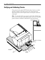
Verifying and Validating Checks
If the printer has the optional MICR check reader, checks are verified
and then validated. If the printer also has the optional check flip
feature, the printer is able to flip the check over and print on the front
of the check.
Note: To ensure that checks are properly verified and validated, they
must be free of folds and wrinkles and inserted correctly into the MICR
printer. Smooth a wrinkled or folded check for best performance.
Check Orientation - Face down
ENDORSE HERE
MEMO
Green
Slip-in LED
Check
Guide
First Line of
Print Guide
Slip
Table
Extended
Slip Table
Chapter 3: Using the Printer
3-11
To verify and validate a check:
2. Place the check, face down on the Slip Table, with the bottom edge
of the check to the right. Move the check to the right until it aligns
against the Check Guide.
3. Slide the check straightforward into the printer until it stops. The
green Slip-in LED on the front of the printer comes on.
Note: IMPORTANT: Hold the check to the right, against the Check
Guide and release it as soon as the printer begins to run.
4. Follow the instructions on the host computer to complete the MICR
process:
a. When instructed by the host, the check is fed into the printer,
read and backed out to a position ready for endorsement, if
desired.
b. With the optional check-flip feature, the check is fed into the
printer, verified, fed up into the check flip mechanism, flipped,
fed back into the printer, printed on the front and released.
Note: If the terminal indicates an incorrect read of the MICR:
•
Remove the check.
•
Reinsert the check, ensuring instructions 1 through 3 above
are followed.
5. Only remove the check when it is fully released by the printer.
6. Continue to follow the instructions from the host computer to
finish the transaction.
3-12
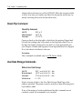
Chapter 3: Using the Printer
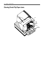
Clearing Check Flip Paper Jams
Check
Check Flip
Window Door
Chapter 3: Using the Printer
3-13
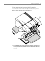
To clear a paper jam from the optional check flip assembly:
1. Look in the window of the check flip assembly. If the jammed
check is visible, open the window and remove it.
Front
Cover
2. If the jammed check is not visible in the window, open the Front
Cover and remove the jammed check from behind the check flip
assembly.
3-14
Chapter 3: Using the Printer
Testing the Printer
The Configuration Menu allows you to set general printer parameters.
The test prints a list of various printer settings and partially cuts the
paper if a knife is installed. The test printouts may vary depending on
the printer model. The printout may be useful to a service
representative if there is a problem. To change the default settings,
enter the Configuration Menu as instructed on the bottom of the test
printout. If something appears to be wrong with the test printout (such
as missing or faded text), see the troubleshooting section in this
document.
1. To run the test, either:
a. Open and close the receipt cover while holding down the Paper
Feed Button.
OR
b. Press the Paper Feed Button and the Reset Button at the same
time.
2.
When the printer begins printing let go of the Paper Feed Button.
Caution: Be extremely careful changing any of the printer settings to
avoid inadvertently changing other settings that might affect the
performance of the printer.
Press the Paper Feed Button the number of clicks for the printer
settings you want.
Note: Press the Paper Feed Button for at least one second to validate
the selection.
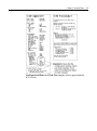
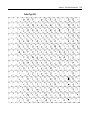
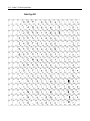
Chapter 3: Using the Printer
Configuration Menu and Print Test samples (show approximately
60% of size).
3-15
3-16
Chapter 3: Using the Printer
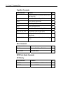
Printer Configuration
Printers are generally shipped with all appropriate configuration
settings pre-set at the factory. The only time the user should need to
change the printer configuration is if a new option is installed or the
firmware is changed. It is also possible the user may need to run
certain tests using the Configuration Menu.
The user configures the printer using a convenient Configuration Menu
that is printed on receipt paper. The Configuration Menu prints
instructions and setting options interactively as the user goes through
the configuration process. The following functions and parameters can
be changed with the scrolling Configuration Menu:
•
Communication Interface
Interface Type
Baud Rate
Number of Data Bits
Number of Stop Bits
Parity
Hardware (DTR/DSR) or Software (XON/XOFF) Flow Control
Data Reception Errors
•
Diagnostic Modes
Normal Mode
Datascope Mode
Receipt Test Mode
Slip Test Mode
MICR Test Mode
Check Flip Test Mode
•
Emulations/Software Options
Printer Emulations
Printer ID Mode
Default Lines Per Inch
Carriage Return Usage
Alternate Commands
Chapter 3: Using the Printer
•
3-17
Hardware Options
Print Density
Maximum Power
Knife Options
Paper Low Sensor
Printhead Resistance
MICR Option
Check Flip Option
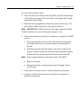
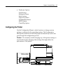
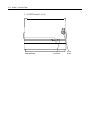
Configuring the Printer
Use the Configuration Menu to select functions or change various
settings as indicated in the preceding sections. The Configuration
Menu prints instructions and setting options interactively as the user
goes through the configuration process.
Caution: Be extremely careful changing any of the printer settings to
avoid inadvertently changing other settings that might affect the
performance of the printer.
Switch 1 is shown
in the ON position
On
Off
4 3 2 1
DIP Switch
DIP Switch
Back of Printer
3-18
Chapter 3: Using the Printer
1. Set DIP Switch 1 to On.
Front of Printer
Front Cover
Reset
Button
Chapter 3: Using the Printer
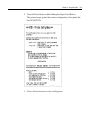
3-19
2. Press the Reset Button while holding the Paper Feed Button.
The printer beeps, prints the current configuration, then prints the
first SELECTION.
3.
Follow all the instructions on the scrolling menu.
3-20
Chapter 3: Using the Printer
4.
Press the Paper Feed Button to make the selections.
The instructions indicate whether to select something with a short click, a
long click, or a series of short clicks. Indicate Yes with a long click, No
with a short click. Press and hold the Paper Feed Button for at least one
second for a long click. Press the Paper Feed Button quickly for a short
click.
5.
When finished, set DIP Switch 1 to Off and reset printer.
6.
Press the Reset Button. The printer resets with the new selections.
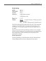
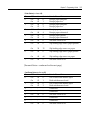
Communication Interface
The Configuration Menu gives the user the option of setting the printer
to use an RS-232C serial port. (See “Configuring the Printer” for
instructions on how to enter the Configuration Menu.)
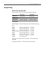
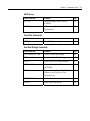
RS-232C Serial Interface Settings
If the user sets the printer to use an RS-232C serial interface, the
Configuration Menu can be used to set the following RS-232C-specific
settings:
•
Set a baud rate of 115200, 57600, 38400, 19200, 9600, 4800, 2400, or
1200 baud
•
Set the number of data bits to seven or eight
•
Set the number of stop bits to one or two
•
Enable or disable parity
•
Set flow control to software (XON/XOFF) or Hardware
(DTR/DSR)
•
Set the printer to ignore data errors or print a “?” upon
encountering an error
The settings used will depend on the software the operator is using
and the capabilities of the host computer.
Chapter 3: Using the Printer
3-21
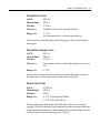
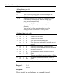
Diagnostic Modes
This function allows the user to put the printer into the following
diagnostic modes:
•
Normal Mode: this is the normal operating mode of the printer.
•
Datascope Mode: the receipt printer prints incoming commands
and data in hexadecimal format.
•
Receipt Test Mode: the receipt printer prints two code pages.
•
Slip Test Mode: the slip printer prints two code pages.
•
MICR Test Mode: the receipt printer prints all characters
recognized by the MICR.
•
Check Flip Test Mode: the check flip mechanism will flip an
inserted check.
These diagnostic modes are enabled or disabled by using the
Configuration Menu. See “Configuring the Printer,” for instructions on
how to enter the Configuration Menu.
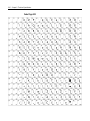
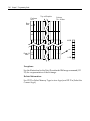
Datascope Mode
Datascope Mode allows the user to test the printer's communications.
When in Datascope Mode the printer receives all communications, but
instead of executing the commands it prints them out on receipt paper
as hexadecimal numbers in the order received. For example, the ASCII
character “A” is printed as the hexadecimal number 41 and so on.
To run the Datascope Mode:
1. Enter the Configuration Menu. See “Configuring the Printer for
instruction on how to enter the Configuration Menu.
2. After you have enabled the Datascope Mode through the
Configuration Menu, exit the Configuration Menu.
3-22
Chapter 3: Using the Printer
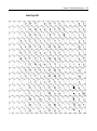
3. Run a transaction from the host computer.
All commands and data sent from the host computer will be
printed as hexadecimal numbers as shown in the illustration.
To exit the Datascope Mode:
1. 1. Enter the Configuration Menu again.
2. Disable the Datascope Mode.
3. Exit the Configuration Menu.
The printer is in Normal Mode and can communicate with the host
computer.
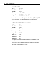
Receipt Test Mode
To run the Receipt Test Mode:
1. Enable the Receipt Test Mode through the Configuration Menu. See
“Configuring the Printer,” for instructions on how to enter the
Configuration Menu.
2. Push Paper Feed Button and the receipt station will print two code
pages.
3. The test ends with a cut.
4. Go to step 2 again to repeat this test.
To exit the Receipt Test Mode:
5. Enter the Configuration Menu again.
6. Disable the Receipt Test Mode.
Chapter 3: Using the Printer
3-23
7. Exit the Configuration Menu.
The printer is in Normal Mode and can communicate with the host
computer.
Slip Test Mode
To run the Slip Test Mode:
1. Enable the Slip Test Mode through the Configuration Menu, (See
“Configuring the Printer,” for instructions on how to enter the
Configuration Menu). Then exit the Configuration Menu.
2. Insert a slip into the slip station.
3. Push the Paper Feed Button.
4. Two code pages will be printed.
5. Go to step 2 again to repeat this test.
To exit the Slip Test Mode:
6. Enter the Configuration Menu again.
7. Disable the Slip Test Mode.
8. Exit the Configuration Menu.
The printer is in Normal Mode and can communicate with the host
computer.
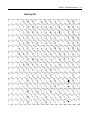
MICR Test Mode
MICR Test Mode allows the user to test whether the MICR is operating
correctly. When the printer is in this mode the MICR reads the
characters on a check as usual, but instead of transmitting the values to
the software it prints them on receipt paper.
To run the MICR Test Mode:
1. Enter the Configuration Menu. See “Configuring the Printer,” for
instructions on how to enter the Configuration Menu.
3-24
Chapter 3: Using the Printer
2. After enabling the MICR Test Mode through the Configuration
Menu, exit the Configuration Menu.
3. Insert a check into the slip station. (See “Verifying and Validating
Checks” section.)
4. The printer waits until a check is inserted and detected before the
platen closes and the characters are read by the MICR check reader.
The decoded data is printed on receipt paper, the platen is opened,
and the test is re-started.
5. The printed numbers should match the numbers on the check. If
the MICR check reader misreads a character, the test prints a
question mark “?”. If the MICR check reader is unable to read any
characters, the test prints “NO MICR CHARACTERS.”
To exit the MICR Test Mode:
6. Enter the Configuration Menu again.
7. Disable the MICR Test Mode.
8. Exit the Configuration Menu.
The printer is in Normal Mode and can communicate with the host
computer.
Chapter 3: Using the Printer
3-25
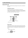
Check Flip Test Mode
To run the Check Flip Test Mode:
1. Enable the Check Flip Test Mode through the Configuration Menu
(See “Configuring the Printer,” for instructions on how to enter the
Configuration Menu), then exit the Configuration Menu.
2. Insert a check as if validating the check, lengthwise and face down
into the slip station. (See “Verifying and Validating Checks” section
to insert check.)
A check must be used—if any other slip or form is inserted the
printer will not conduct the test.
Check Orientation - Face down
ENDORSE HERE
MEMO
Green
Slip-in LED
Check
Guide
First Line of
Print Guide
Slip
Table
Extended
Slip Table
3-26
Chapter 3: Using the Printer
3. Push Paper Feed Button.
The check then goes through the flip routine only—no printing takes
place.
To exit the Check Flip Test Mode:
4. Enter the Configuration Menu again.
5. Disable the Check Flip Test Mode.
6. Exit the Configuration Menu.
The printer is in Normal Mode and can communicate with the host
computer.
Emulation/Software Options
Printer Emulations
Printer emulations determine the commands that are available to the
printer. They are set by using the Configuration Menu. (See
“Configuring the Printer” for instructions on how to enter the
Configuration Menu.) The available options are:
•
7158 Native (enables all new functions)
•
7156 Emulation (for use with legacy software)
Printer ID Mode
This switch is used to determine what Printer ID value is returned in
response to a Transmit Printer ID (1D 49 01) when the printer is in 7156
Emulation Mode. The printer can be configured to send back the ID of
the 7158 or the 7156.
Chapter 3: Using the Printer
3-27
Default Lines Per Inch
This function allows the user to set the default lines per inch printed by
the thermal receipt printer to 6, 7.52 or 8.13. (See “Configuring the
Printer” for instructions on how to enter the Configuration Menu to
change this setting.)
Carriage Return Usage
This function allows the printer to ignore or use the Carriage Return
(hexadecimal 0D) command depending on the application. Some
applications expect the command to be ignored while others use the
command as a print command. (See “Configuring the Printer” for
instructions on how to enter the Configuration Menu to change this
setting.)
Hardware Options
Print Density
This function makes it possible to adjust the energy level of the
printhead to darken the printout. An adjustment should only be made
when necessary. The factory setting is 100%.
Warning: Choose an energy level no higher than necessary to
achieve a dark printout.
Failure to observe this rule may result in a printer service call or
voiding of the printer warranty. Consult your NCR technical support
specialist if you have any questions.
Maximum Power
This function makes it possible to match the printer to the wattage of
the power supply. The 55 W power supply is standard, whereas the 75
W power supply enables the printer to optimize speed at higher dot
coverage. (See “Configuring the Printer” for instructions on how to
enter the Configuration Menu to change this setting.)
3-28
Chapter 3: Using the Printer
Knife Option
This function makes it possible to set the Knife Option if it is installed
in the printer. This setting should only be changed if the option is
added or removed.
Paper Low Sensor
Paper Low Sensor setting makes it possible to enable or disable the
paper low sensor for particular printer configurations.
Printhead Resistance
The printhead in the thermal receipt printer can be one of two types.
The printhead resistance setting must match the character (A or B)
stamped on the heatsink in the back of the printhead. This character is
visible by removing the top cover of the printer. Only a trained service
representative may remove this cover. Therefore, under normal use
this setting should be left at the factory default.
Using the Configuration Menu sets the printhead resistance settings.
See “Configuring the Printer” for instructions on how to enter the
Configuration Menu.
MICR Option
This function makes it possible to set the MICR Option if it is installed
in the printer. This setting should only be changed if the option is
added or removed.
Check Flip Option
This function makes it possible to set the Check Flip Option if it is
installed in the printer. This setting should only be changed if the
option is added or removed.
Chapter 3: Using the Printer
3-29
Basic Troubleshooting
The 7158 printer is a simple, generally trouble-free printer, but from
time to time minor problems may occur. For example, the power
supply may be disconnected or the thermal printhead may overheat.
The On Line, Paper Status, Error LED on the operator panel may signal
that something is wrong. The light on the front right side of the printer
is used only to indicate when a form is inserted properly. It does not
indicate an error.
For some problems, the printer communicates the information to the
host computer and relies on the application to indicate what the
problem is.
The information on the following pages describes some problems that
you may encounter: problems that you can easily fix, and others that
you will need to contact a service representative for.
You may be able to correct many of the conditions or problems without
calling for service. However, if a problem persists, contact a service
representative. See “Contacting a Service Representative” at the end of
this chapter.
3-30
Chapter 3: Using the Printer
If something is wrong with the printer, take the following general
steps:
•
Cycle the power of the printer and note its behavior.
•
Check the On Line, Paper Status, Error LED and compare its
behavior to the table below.
Status
LED Behavior
Power Off
Off
Firmware Download
Fast Blink
Level 0 Diagnostics (entered at power on or in reset)
Fast Blink
Paper Low
Temperature Error
Voltage Error
Slow Blink
Cover Open (receipt, slip or flip)
Paper Out
Carriage Jam
Slip Jam
Flip Jam
Knife Jam
Fast Blink
All other states
On
•
Test the receipt printer or slip printer by printing a sample test
print as described elsewhere in this document.
•
Determine if the problem is with the thermal receipt printer or the
impact slip printer and refer to the tables on the following pages.
Chapter 3: Using the Printer
3-31
Printer Beeps
Problem/Symptom
Possible Causes
What to Do
Printer beeps in a single, double, or triple The printer has a problem with
its electronics.
pattern at first power on, the On Line,
Paper Status, Error LED blinks in the
same pattern, and the printer won’t
power up.
Contact a service
representative.
Printer beeps during normal operation.
Consult your
application
software manual.
The printer may be programmed
to beep during normal operation
by the software application used
on the host computer.
3-32
Chapter 3: Using the Printer
Printer Will Not Print
Problem/Symptom
Possible Causes
What to Do
The On Line, Paper
Status, Error LED is
blinking and the printer
won’t print.
The receipt paper may
be out, the cover open,
the knife jammed, the
supply voltage out of
range, or the printhead
temperature out of
range.
Check that the receipt paper is properly loaded and
covers are closed. See the table at the beginning of this
section. For problems not user correctable, contact a
service representative.
Printer doesn't have
power (LED not on)
Power supply may be
defective.
If the power supply is plugged in, but does not come
on, you will need to order a new power supply. See
“Media and Supplies” in this document.
Printer has power but
doesn't print.
Cables may not be
connected properly.
Check all cable connections. Check that the host
computer and power supply are both on (the power
supply is turned on by plugging it into an outlet). See
“Connecting the Cables” in this document.
DIP Switches not set
correctly.
Check the switch setting. DIP Switch one should be
off (down) for normal operation.
All other causes.
Contact a service representative.
Chapter 3: Using the Printer
3-33
On-Line, Paper Status, Error LED Flashes
Problem/Symptom
Possible Causes
What to Do
On Line, Paper
Status, Error LED is
blinking.
Receipt paper is out. Change the
paper now. Do not run a
transaction without paper as the
data may be lost.
Change the paper immediately. See “Loading
and Changing the Receipt Paper” in the Owner’s
Guide.
Receipt, front or flip cover is
open.
Close the cover. The printer will not operate with
any of the covers open.
The knife is jammed.
Open the receipt cover and check the knife. Clear
any jammed paper you can see. Tear off any
excess paper against the tear-off blade.
The slip is jammed.
Open the Front Cover and clear paper from path.
The carriage is jammed.
Open Front Cover and clear paper from path.
A jam during flip.
If visible through Front Window, open access
door and clear paper jam, if not, open Front
Cover and clear jam.
Receipt paper is low.
There are about 4.5 meters, ± 3 meters, (15 feet, ±
10 feet) of paper left. Change the paper soon to
avoid running out of paper part way through a
transaction. See “Loading and Changing the
Receipt Paper” in this document.
AC supply voltage is out of
range.
If paper is not low and no conditions indicate
that the thermal printhead is too hot, then it is
likely that the power supply voltage is out of
range. Contact a service representative.
Thermal printhead temperature
is out of range.
The printhead may overheat when printing in a
room where the temperature is above the
recommended operating temperature or when
printing high density graphics continuously,
regardless of the room temperature. In either
case, the printer will shut off. If the temperature
of the printhead is too hot, adjust the room
temperature or move the printer to a cooler
location. If the printhead is overheating because
of printing high density graphics continuously,
reduce the demand on the printer.
On Line, Paper
Status, Error LED is
blinking.
3-34
Chapter 3: Using the Printer
Poor Forms Print Quality
Problem/Symptom
Possible Causes
What to Do
Printer starts to print, but
stops while the form is being
printed.
Communication error or
software error.
Check the interface cable. Check
that the software is working
properly.
Forms print is light or spotty.
Form not inserted
incorrectly.
See “Printing on Forms or Checks”
in this document.
Impact printhead is dirty
or defective.
Contact a service representative.
Improper internal cable
connections.
Contact a service representative.
Ribbon cassette is worn.
Replace the ribbon
cassette.
See “Replacing the Ribbon Cassette”
in this document.
Light print, smudging, or slip
skews.
Platen gap needs
adjustment.
Contact a service representative.
Poor Receipt Print Quality
Problem/Symptom
Possible Causes
What to Do
Colored stripe on receipt.
Paper is low.
Change the paper.
Receipt does not come out all Paper is jammed.
the way.
Open the receipt cover, inspect
the knife, and clear any jammed
paper.
Printer starts to print, but
stops while the receipt is
being printed.
Paper is jammed.
Open the receipt cover, inspect
the knife, and clear any jammed
paper.
Print is light or spotty.
Paper roll loaded incorrectly.
Check that the paper is loaded
properly.
Chapter 3: Using the Printer
Thermal printhead is dirty.
3-35
Use recommended thermal
receipt paper. Clean the thermal
printhead with an alcohol pen.
Do not spray the thermal
printhead with household
cleaner as this may damage it
and the electronics. The thermal
printhead does not normally
require cleaning if the
recommended paper grades are
used. If non-recommended
paper has been used for an
extended period of time,
cleaning the printhead with an
alcohol pen will not be of much
benefit.
Contact a service
representative.
Improper internal cable
connections.
Contact a service
representative.
Printhead is defective.
Printhead is defective.
Vertical column of print is
missing, one side of receipt is
missing, or top or bottom
half of characters are
missing.
Contact a service
representative.
Print cassette ribbon jams
when check flip option is
used.
Replace cassette with a cassette
approved for the check flip
option.
Improper ribbon cassette. An
approved NCR cassette must
be used with the check flip
option.
3-36
Chapter 3: Using the Printer
Slip Station, MICR and Flip Problems
Problem/Symptom
Possible Causes
What to Do
Slip Table LED
does not come
on.
Form or check not
inserted properly.
Line up the form or check against the Check Guide
(wall) and slide it toward the back of the printer
until it contacts the Form Stop and can't go any
further. Extra long forms may need to be inserted
from the side to disengage the Form Stop. See
“Printing on Forms or Checks” or “Validating and
Verifying Checks” in this document.
Forms or checks
skew or catch in
the slip station.
There is an obstruction or
paper jam in the slip
station.
Open the front cover and check for any paper jams
or obvious obstruction in the slip station. Clear the
obstruction or jammed paper.
The optional
check flip
mechanism
doesn’t work.
There is an obstruction or
paper jam in the check
flip mechanism.
See “Clearing Paper Jams” in this document.
The check is inserted
The optional
MICR (Magnetic improperly.
Ink Character
Recognition)
check reader does
The check is fraudulent.
not read or
misreads checks.
A nearby magnetic source
is interfering with the
check reader.
Print cassette
ribbon jams when
check flip options
is used.
Improper ribbon cassette.
Approved NCR cassette
must be used with the
check flip option.
Make sure the check is inserted properly with the
MICR characters down. See “Validating and
Verifying Checks” in the Owner’s Guide.
Make sure that the check is not fraudulent. On
fraudulent checks, the characters the printer reads
may be different from those that are visible on the
check face.
Devices, such as CRT monitors, security devices or
large metal surfaces that are near the printer can
affect the printer's magnetic field, causing
intermittent reading errors when the MICR check
reader is in operation. Move the printer away
from such items or areas.
Replace cassette with a cassette approved for the
check flip option.
Chapter 3: Using the Printer
3-37
Knife Does Not Operate
Problem/Symptom
Possible Causes
What To Do
Receipt is not cut.
Paper is jammed.
Open the receipt cover, inspect
the knife, and clear any jammed
paper.
The printer has a knife but the
firmware is not configured for a
knife.
All other problems.
Enable the knife option by
reconfiguring the printer. See
“Configuring the Printer” in this
document.
Contact a service representative.
3-38
Chapter 3: Using the Printer
Other Serious Problems
The following problems all need to be corrected by a qualified service
representative. See the next section, “Contacting a Service
Representative.”
•
MICR check reader not operating properly
•
Forms not feeding into the slip/forms area properly
•
Missing dots in slip or forms printing
•
Printer will not cycle or stop when required
•
Illegible characters
•
Paper will not feed
•
Knife will not cycle or cut
•
Platen will not open or close
•
Printer will not communicate with the host computer
Contacting a Service Representative
For serious problems, such as the printer not printing, not
communicating
with the host computer, or not turning on, contact NCR technical
support.
For self-maintenance organizations, a service guide, service video,
parts manual, and other service documents, can be obtained from NCR.
Chapter 3: Using the Printer
3-39
Returning a Printer
Follow these instructions if you need to return a printer for servicing.
1. If you are sending the printer to NCR for repair, call NCR for a
Return Material Authorization number (RMA#). Be prepared to
answer questions concerning shipping and billing. Request an
RMA process be sent to you, if required.
2. Pack the printer as follows:
Receipt
Cover
Receipt
Paper
3-40
Chapter 3: Using the Printer
a. Place receipt paper between the receipt cover and the printhead
for protection.
Front
Cover
Cardboard
Support
Carriage
Foam
Restraint
b. Remove the ribbon cassette, move the carriage to the right, and
place the foam restraint between the left side of the printer and
the carriage to protect the carriage.
c. Place the cardboard support on the Slip Table.
d. Place the printer in the plastic bag and foam pack, place the
packed printer in the box and secure the box with packing tape.
3. Write the RMA# on the outside of the box and send the printer to
the following address, according to the RMA process:
NCR
The nearest NCR service center address
City, State zip
U.S.A.
RMA # 907456 (sample number for example only)
Chapter 4:
Printer & Media Supplies
Ordering Thermal Paper
Thermal Paper Specifications
The printer requires qualified thermal paper with the following
dimensions:
Width
Diameter
Length
80 mm + .2 mm - .6 mm
(3.15 + .008 in. - .024 in.)
90 mm max.
(3.54 in.)
98 meters (322 ft.) 2.4 mil thick
73.5 meters (241 ft.) 3.2 mil thick
The paper must not be attached at the core. Use paper with a colored stripe at
the end to indicate that the paper is running low.
The above lengths are based on a core diameter of 22 ± .5 mm (.87 in.) outside,
1.5 ± .5 mm (.45 in.) inside.
NCR can provide paper in small lots to facilitate product evaluation
and testing.
To order paper rolls, contact your sales representative or order directly
from NCR at the following address or toll free number:
NCR Corporation
Systemedia
9995 Washington Church Road
Miamisburg, OH 45342
1-800-543-8130
Use the following part numbers:
Standard Density
50 Rolls, 90mm diameter
NCR #A152-0034
Light Density
50 Rolls, 90mm diameter
NCR #A152-0035
4-2
Chapter 4: Printer & Media Supplies
Ordering Parts and Supplies
Ordering Cash Drawers
Order cash drawers from the following suppliers:
Cash Drawers
Number
NCR
7052-K657
Ordering Power Supply Cord and Adapters
Contact your sales representative to order the power supply and power
cords listed in the table. The numbers are for NCR reference only.
Suppliers may use other numbers.
Item
Type
Number
Power supply (55 watt) with attached cable to
printer and U.S. power supply cord
7158-K330
Power supply (75 watt) with attached cable to
printer and U.S. power supply cord
7158-K331
Power supply (55 watt) attached cable
7158-K301
Power supply (75 watt) attached cable
7158-K302
Power supply cord (to outlet)
United States
International (no
plug)
United Kingdom
S.E.V.
Australia
International
(with plug)
7158-K320
7158-K321
7158-K322
7158-K323
7158-K324
7158-K326
6-pin female to 3-pin male power adapter
7158-K303
3-pin female to 6-pin male power adapter
7158-K304
Chapter 4: Printer & Media Supplies
4-3
Ordering Communication Cables
Contact your sales representative to order the communication cables
listed in the table. The numbers are for reference only. Suppliers may
use other numbers.
Communication Cables
Length
Order Number
RS-232C 9-pin to 9 pin
(0.7 meters—2 ft.)
1416-C359-0007
RS-232C 9-pin to 9 pin
(4.0 meters—13 ft.) 1416-C266-0040
Forms Specifications
The 7158 prints on single- or multiple-part forms in the slip station (up
to five-part forms). Forms and slips must meet the following
requirements:
•
Front insertion (minimum):
51 mm (2.00 inches) wide
68 mm (2.68 inches) long
•
Side insertion (minimum):
203 mm (8.0 inches) wide
51 mm (2.0 inches) long
•
Single-ply forms should be on paper that is greater than 15 pounds
•
Multiple-part forms (up to five parts) should be no thicker than .40
mm
(.016 inches) and a minimum thickness of .08 mm (.003 inches).
Note: Do not use forms containing holes along the top or right
edge.
•
Forms for use with Flip Check (minimum)
51 mm (2.00 inches) wide
70 mm (2.75 inches) long
4-4
Chapter 4: Printer & Media Supplies
Check Specifications
Check American Standards ANSI X9.13 and ANSI X9.18, and
International Standard ISO 1004 define specifications for paper.
•
Minimum check size: 70 mm (2.75 in.) wide x 152 mm (6.00 in.) long
•
Maximum check size: 95 mm (3.75 in.) wide x 222 mm (8.75 in.)
long
Ordering Ribbon Cassettes
To order ribbon cassettes, contact your sales representative or order
from NCR at the following address or toll free number:
NCR Corporation
Systemedia
9995 Washington Church Road
Miamisburg, OH 45342
1-800-543-8130
Ordering Extended Slip Tables
Contact a sales representative to order slip tables. The numbers listed
below are for reference only. Suppliers may use other numbers.
Extended Slip Table (Standard)
7158-K280
Extended Slip Table (Short)
7158-K281
Ordering Documentation
See the IP Web Site (http://info.ncr.com)for the following online
documentation:
Item
Number
7158 Owner’s Guide
7158-0000-1112
7158 Service Guide
7158-0000-1113
Chapter 5: Technical Specifications
Functional Description
Standard Slip Features
Print Technology
Bidirectional, logic-seeking, nine wire impact printhead
Printhead Features
Automatic homing and jam detection
Ink Means
3 or 5 million character life
Carriage mounted ribbon cassette
Print Resolution
Standard 139 DPI X 72 DPI
Compressed 171 DPI X 72 DPI
Character Cell
10 Half Dots x 7 Dots High
Print Line Width
Standard 66 characters @ 13.9 CPI
Compressed 80 characters @ 17.1 CPI
Enhanced Print
Double wide and rotated character
Double strike to improve contrast
Print Line Spacing
Standard 7.2 lines/inch
Print Line Rate
Full 40 columns at 290 LPM @ 13.9 CPI
Paper Feed
Bi-directional, 4.6 IPS, maximum
Forms Handling
Horizontal Slip Table
Retractable slip stop
Front/side insertion
5-2
Chapter 5: Technical Specifications
Forms Capability
* See notes on the
following page.
Maximum thickness .40 mm (.016 inch) max., 5 plies
Minimum .08 mm (.003 inch)
Minimum Form Reflectivity 60%
Minimum Length: 68 mm (2.68 inches) w/o check flip
option
70 mm (2.75 inches) with flip option
Minimum Width:
51 mm (2.00 inches)
[Ensures that forms cover both the optical slip detectors
and expose about one inch of the form to push in place.]
Forms Detection
Leading edge sensor at forms stop
Trailing edge sensor in right margin.
Indicators
Green LED "Slip-in" light
Character Sets
PC Code Page 437
PC Code Page 850
PC Code Page 852
PC Code Page 858
PC Code Page 860
PC Code Page 863
PC Code Page 865
PC Code Page 866 resident
Additional Flash memory for user-defined characters
Graphics
139 DPI X 72 DPI bit-mapped, input as 7 and 8 dot high
unidirectional print lines.
Bar Code Fonts
UPC-A
UPC-E
JAN8
JAN13 (EAN)
Code 39
Interleaved 2 of 5
Codabar
Code 128
Code 93
Chapter 5: Technical Specifications
5-3
Slip Forms - Recommendations
The slip form should be flat and void of curls or wrinkles, especially at
the top.
Considerations for bound edges on slip paper (multi-page forms):
•
Binding on the leading edge (top): Best method, however paper
feeding and insertion can be affected by the binding method, the
length of the edge, and the quality of glue used.
•
Binding on the right edge: Paper feeding and insertion can be
affected by the binding method, the length of the edge, and the
quality of glue used.
•
Binding on the Left edge or wide slip paper: Skewing may occur.
•
Binding on the bottom edge: Not recommended
Direction of
Paper Feed
Bound Edge on Top or Right
Paper feeding and insertion
affected by the binding method,
length of page, and the quality of
the adhesive used.)
Bound Edge on Left
Scewing can occur
Bound Edge on Bottom
Do NOT use
20526
5-4
Chapter 5: Technical Specifications
MICR
Head
Slip
Sensor
Slip/LED
Sensor
Slip Side
Guide
19 mm
(0.747 in.)
8 mm
(0.315 in.)
6 mm
(0.236 in.)
Slip
Edge
Paper Feed
Direction
Paper Holes and
Low Reflection
Prohibited Areas
B
A
The Slip/LED Sensors use a reflective photo sensor.
•
Do not use paper that has holes or is translucent at the Slip/LED
Sensor location. (See “A” in above illustration.)
•
Do not use paper that has holes on dark areas with low reflection
(less than 60% reflection) at the Slip Sensor location. (See “B” in
above illustration.)
•
Thin paper should be used between the top and bottom sheets of
multi-ply paper. Thick paper reduces the copy capability.
Chapter 5: Technical Specifications
5-5
MICR Reader – Additional Information
•
The check must be flat and void of curls, folds, or wrinkles
(especially at the edges). Wrinkled checks may rub against the
ribbon causing them to become ink-stained.
•
Checks must be void of clips or staples. Paper jams, MICR read
errors, and/or MICR head damage could occur.
•
Immediately release the check once the printer starts to feed it.
Failure to release the check could skew it, causing paper jams and
MICR read errors.
Standard Receipt Features
Print Technology
Direct thermal
640 dot printhead
Print Resolution
203 DPI horizontal and vertical
8 dots/mm
Character Cell
Standard 13 X 24
Compressed 10 X 24
Print Width
Standard 44 characters @ 15.6 CPI
Compressed 56 characters @ 20.3 CPI
Enhanced Print
Double Wide, Double High, Rotated, Underlined,
Scalable, Italic, Superscript, Subscript, Bold, and Reversed
Image characters
Print Line Spacing
7.52 lines/inch, standard
Print Line Rate
38.4 LPS for text at standard spacing. See Receipt
Throughput
Paper Feed
Unidirectional, 130mm/second maximum. See Receipt
Throughput
Paper Sensing
Paper exhaust switch
Paper low switch (adjustable).
Operator Interface
Paper Feed Button on cabinet
5-6
Chapter 5: Technical Specifications
Character Sets
PC Code Page 437
PC Code Page 850
PC Code Page 852
PC Code Page 858
PC Code Page 860
PC Code Page 863
PC Code Page 865
PC Code Page 866 resident
Additional Flash memory for user-defined characters
Graphics
203 DPI X 203 DPI bit-mapped, input as 24 dot high print
lines
Bar Code Fonts
UPC-A
UPC-E
JAN8
JAN13 (EAN)
Code 39
Interleaved 2 of 5
Codabar
Code 128
PDF-417 Two-dimensional Code
Code 93
Chapter 5: Technical Specifications
5-7
Optional Features
Paper Cutter
Rotary partial cut knife leaves 5.0 mm (0.2 inch) uncut on
left edge.
Slip Table Kits
Extends Slip Table 38 mm (1.5 in.) or 76 mm (3.0 in.) in
front. The 76 mm slip table comes standard with the
MICR and Flip options.
MICR Reader
Integrated into the slip station.
Reads MICR checks oriented for validation on the back of
the check, and communicates the character string to the
host computer.
Reads E13B and CMC7 MICR Fonts (Auto discriminates).
Check Flip
Error and fraud prevention feature.
Turns validated checks over for printing on the face of the
check.
Remote Power
Supply
55W standard
75W available
Auto-Ranging input
24Vdc output
Interface daughter
PCBs
RS-232C, 9 pin connector
USB
5-8
Chapter 5: Technical Specifications
Reliability
The numbers in the table refer to the Mean Cycles Between Failure
(MCBF) for the items indicated.
Thermal Receipt Printer
45 Million Lines
Impact Slip Printer
15 Million Lines
Impact Printhead
200 Million Characters
Knife
1.5 Million Cuts
MICR Check Reader
200,000 Reads
Ribbon Cassette
3 or 5 Million Characters
Check Flip
200,000 Flips
Electronics
240,000 hours (MTBF)
Chapter 5: Technical Specifications
Certifications
EMI:
•
FCC, Class A
•
Industry Canada, Class A
•
VCCI, Class A
•
CE Mark, Class B
•
Austel, Class B
Safety:
•
UL 1950
•
CSA 22.2 No. 950
•
CE Mark (EN60950)
5-9
5-10
Chapter 5: Technical Specifications
Physical and Operating Environment
Temperature and Humidity
Temperature in Degrees
Operating: w/ Knife
%Humidity
5C to 28C ( 41F to 82F)
10 to 90
28C to 45C ( 82F to 113F)
10 to 35
5C to 35C ( 41F to 95F)
5 to 90
35C to 50C ( 95F to 122F)
5 to 40
Storage:
-10C to 50C ( 14F to 122F)
5 to 90
Transit:
-40C to 60C (-40F to 140F)
5 to 95
Operating: w/o Knife
Electrical
The 7158 printer complies with the regulatory EMI standards and
levels indicated in the section on Certifications when tested as a standalone unit.
When connected to a host terminal or system, the 7158 also complies
with these standards and levels, provided that the host terminal or
system first complies without the 7158 printer connected.
Slip Media
The 7158 prints 1 to 5 part forms with the following limitations:
•
The minimum thickness of a single part form is .08 mm (.003 inch).
•
If present in a multi-part form, cardstock will be the bottom part.
•
Maximum total thickness is .40 mm (.016 inch).
•
Minimum form reflectivity is 60%
Chapter 5: Technical Specifications
5-11
Minimum form length (feed direction) for forms inserted from the
front up to the slip stop is 68 mm (2.68 inches) w/o check flip option
and 70 mm (2.75 inches) w/Flip option. Minimum form width (print
direction) is 51 mm (2.00 inches). These minimums ensure the form
covers both optical slip detectors, and expose about one inch of the
form to push in place.
The form must be at least 127 mm (5.00 inches) wide to print all 66
standard or 80 compressed columns. Large forms may be inserted
from the left side and override the slip stop. Forms over 170 mm (6.70
inches) wide will extended outside the left side of the printer.
Receipt Media
•
Direct thermal paper, with or without environmental coating.
•
Paper thickness range:
51–86 µm (2.0–3.4 mil).
•
Receipt roll width:
80 + .2 - .6 mm (3.150 + .008 - .024 inch).
•
Receipt roll diameter:
90 mm (3.54 inch) maximum.
•
Receipt roll capacity: *
98M (322 feet) of 61µm (2.4 mil) thick
paper
73.5M (241 feet) of 81µm (3.2 mil) thick
paper
•
Roll construction:
Image side facing out.
•
End-of-roll warning:
Stripe recommended, not required.
* Based on core diameter of: 22 ± .5 mm (.87 inch) outside,
11.5 ± .5 mm (.45 inch) inside.
5-12
Chapter 5: Technical Specifications
Migration
The 7158’s standard command set allows it to work with software
written for NCR or other ESC/POS™ compliant printers.
The 7158 supports two modes of operation: “A756 emulation” and
“A758 native” modes. When the 7158 is configured for A756 emulation
mode through the Configuration Menu, the printer is backward
compatible to 7156 slip and receipt applications except that receipt
print resolution is increased from 6 to 8 dots/mm. If the 6 to 8 dot/mm
conversion features are not used, this will result in the size of graphics
being reduced by 25%.
See Chapter 7: Programming Guide for a comparison to the 7156.
Performance Requirements
Slip Printing
Slip Positioning
Forms are inserted from the front, top-of-form first, up to a form stop
behind the carriage, or inserted from the left side and over-ride the
form stop. In each case the form must be aligned with the check guide
(right edge of the slip path). A pair of optical sensors are located (a) 11
mm (.45 inch) above the print centerline and 25 mm (1.00 inch) from
the check guide, and (b) just inside the check guide and 37 mm (1.45
inches) below the print centerline. The application can use these for
form-in and trailing edge detection. A green slip-in LED indicates
when both detectors are covered.
The application moves the form bi-directionally in 1/72-inch
increments to position the first line of print.
Chapter 5: Technical Specifications
5-13
Slip Format
Maximum print line width: 120.7 mm (4.752 inches) starting 3.20 mm ±
1.5 mm (.125 inch ± .060 inch) from the right edge of the form.
Standard Font
Compressed Font
Character Cell
10 half dots x 7 dots
10 half dots x 7 dots
Character Size
7x7
7x7
Character Per Line
66 @ 13.9 CPI
80 @ 17.1 CPI
Graphics Capability
330 full dots
660 half dots
N/A
N/A
Print line height: 7 dots @ 1/72 inch + Extra Dot Rows:
0 EDR between lines:
1 EDR:
2 EDR:
3 EDR (standard):
4 EDR:
5 EDR:
N EDR:
2.47 mm (.097 inch) ±5%
2.82 mm (.111 inch) ±5%
3.18 mm (.125 inch) ±5%
3.53 mm (.139 inch) ±5%
3.88 mm (.153 inch) ±5%
4.23 mm (.167 inch) ±5%
(7+N)/72 in. ±5%
= 10.3 LPI
= 9.0 LPI
= 8.0 LPI
= 7.2 LPI
= 6.5 LPI
= 6.0 LPI
Minimum top margin (form against form stop):
16.0 mm (.63 inch)
Minimum top margin (after reverse feeding):
5.0 mm (.20 inch)
Minimum bottom margin:
15.0 mm (.59 inch)
5-14
Chapter 5: Technical Specifications
Slip Throughput
Bi-directional line speed is based on a printhead speed of 260 CPS.
Throughput (±5%) at the standard line spacing (7.2 LPI) depends on
line length expressed in characters:
Line Length
Character Density
Lines Per Minute
40 Chars.
13.9 CPI (standard)
290 LPM
52 Chars.
13.9 CPI (standard)
237 LPM
66 Chars.
13.9 CPI (standard)
195 LPM
80 Chars.
17.1 CPI (compressed)
166 LPM
Unidirectional (graphics) line speed, will be half the above throughput.
Minimum form width for full width print = 127 mm (5.00 in.)
Printable Zone, 330 Full Dots = 120.7 mm (4.752 in.)
Nominal Margins = 3.2 mm (0.125 in.)
Top Edge
Minimum with Slip Stop 16.0 mm (0.630 in.)
Minimum 15.0 mm (0.59 in.)
Trailing Edge
Chapter 5: Technical Specifications
5-15
Character Format
The 7158 can place 66 standard characters, or 80 compressed
characters, or 33 rotated characters, or 330 adjacent bits of graphics (660
addressable positions) in the 121 mm (4.752 inch) wide print zone.
Minimum line height is 7 dots (.097 inch) for vertical print or graphics,
and 6 dots (.083 inch) for rotated print.
E
C
A
1 3 5 7 9
D
EDR*
B
1 2 3 4 5 6 7 8 9 10
1
2
3
4
5
6
7
2 4 6 8 10
Double Wide
G
Next Line
E
C
* Extra Dot Rows
A
F
D
B
1
2
3
4
5
6
1 2 3 4 5 6 7 8 9 10
Rotated
5-16
Chapter 5: Technical Specifications
Dimension
Standard
mm
inch
Compressed
mm
inch
Rotated
mm
inch
A
.36
.0144
.30
.0117
.36
.0144
B
.35
.0139
.35
.0139
.35
.0139
C
1.46
.0576
1.19
.0468
2.56
.1008
D
2.47
.0973
2.47
.0973
1.76
. 0695
E
1.83
.0720
1.48
.0585
3.66
.1440
F
N/A
N/A
N/A
N/A
2.11
.0834
G
.35
Max.
.014
Max.
.35
Max.
.014
Max.
.35
Max
.
.014"
Max.
Allowable Duty Cycle (measured over one minute of continuous
printing)
The impact printhead can continuously print the following average
number of characters over a one minute period.
Ambient Temperature in degrees:
5C
20C
35C
50C
11.5 Dots/Char. avg.:
7200CH
6000CH
4800CH
3600CH
15.0 Dots/Char. avg.:
5700CH
4800CH
3900CH
3000CH
19.0 Dots/Char. avg.:
4200CH
3600CH
3000CH
2400CH
No one print wire may exceed 18% of the dots printed.
Ribbon Life
The snap-on purple and black ink ribbon cassettes are available in 3
and 5 million character cartridge lives.
Chapter 5: Technical Specifications
Receipt Printing
Receipt Format, 80mm Paper Width
Print line width: 576 dots @ 8 dots/mm centered on 80 mm.
Standard Font
Compressed Font
Character Cell
13 x 24 dots
10 x 24 dots
Character Per Line
44 @ 15.6 CPI
56 @ 20.3 CPI
Nominal Margins
4.25 mm (.167 inch)
5.00 mm (.200 inch)
Minimum Margins
2.00 mm (.079 inch)
2.50 mm (.098 inch)
Print line height: 24 dots @ 8 dots/mm + Extra Dot Rows between
lines
0 EDR:
3.00 mm (.118 inch) ±3%
1 EDR:
3.12 mm (.123 inch) ±3%
2 EDR:
3.25 mm (.128 inch) ±3%
3 EDR (Standard): 3.37 mm (.133 inch) ±3%
4 EDR:
3.50 mm (.138 inch) ±3%
5 EDR:
3.62 mm (.143 inch) ±3%
10 EDR:
4.25 mm (.167 inch) ±3%
N EDR:
(3 + N/8) mm ±3%
=
=
=
=
=
=
=
8.47 LPI
8.13 LPI
7.81 LPI
7.52 LPI
7.25 LPI
7.00 LPI
5.98 LPI
Top margin to manual tearoff: (non-Knife) 9.75 mm (.384 inch)
minimum.
Top margin to knife cut: 17.80 mm (.700 inch) minimum.
5-17
5-18
Chapter 5: Technical Specifications
Print Zone
Paper Width = 80 mm (3.15 in.)
Printable Zone, 576 Dots = 72 mm (2.835 in.)
Nominal Margins, 4 mm (0.157 in.)
Cut Edge
Cut Edge
Top Margin, 17.8 mm (.70 in.) Minimum
44 Standard Columns = 71.5 mm (2.815 in.)
56 Compressed Columns = 70 mm (2.756 in.)
The application centers 44 standard character cells (13 X 24 dots), or 56
compressed character cells (10 X 24 dots), or 576 addressable bits of
graphics across an 80 mm wide receipt. Minimum print line height is
24 dots for text or graphics. Standard print line spacing is 27 dots (i.e. 3
extra dot rows).
Chapter 5: Technical Specifications
5-19
When printing graphics or logos, converted from 6 dot/mm to 8
dot/mm (i.e. designed for 7156), the printable zone is expanded to 598
dots.
Character Pattern for Standard 15.6 CPI Pitch
5-20
Chapter 5: Technical Specifications
11 Dots
1.368 mm
0.054 in.
13 Dots
1.625 mm
0.064 in.
Character
Cell
Character
19 Dots
2.388 mm
0.094 in.
24 Dots
3.00 mm
0.118 in.
B - Upper Case
m - Lower Case
g - With Descender
Ö - With Ascender
$ - Both Ascender and Decsender
# - Graphic Symbol
Character Pattern for Compressed 20.3 CPI Pitch
8 Dots
.995 mm
.039 in.
Character
Character
Cell
19 Dots
2.388 mm
.094 in.
10 Dots
1.244 mm
.049 in.
24 Dots
3.00 mm
.118 in.
B - Upper Case
m - Lower Case
g - With Descender
Ö - With Ascender
$ - Both Ascender and Decsender
# - Graphic Symbol
Chapter 5: Technical Specifications
5-21
Receipt Throughput:
Maximum throughput is achieved at any dot coverage up to 25%,
which includes any amount of text. But above that, throughput is
dependent on the dot coverage and available electrical power.
25% Dot Coverage
(Max Speed)
50% Dot Coverage
and 75 W
50% Dot Coverage
and 55 W
100% Dot Coverage
and 75 W
100% Dot Coverage
and 55 W
Dot line period:
0.95 ms
0.95 ms
1.33 ms
2.05 ms
3.3 ms
Paper Speed:
130 mm/sec
130 mm/sec
94 mm/sec
61 mm/sec
38 mm/sec
5.1 IPS
5.1 IPS
3.7 IPS
2.4 IPS
1.5 IPS
Throughput @
8.13 LPI:
41.5 LPS
41.5 LPS
30.1 LPS
19.5 LPS
12.2 LPS
Throughput @
7.52 LPI:
38.4 LPS
38.4 LPS
27.8 LPS
18.0 LPS
11.3 LPS
Throughput @
5.98 LPI:
30.5 LPS
30.5 LPS
22.1 LPS
14.4 LPS
9.0 LPS
Note: Standard receipt has approximately 12% dot coverage.
A full line of text is approximately 25% dot coverage.
Graphics are approximately 40% dot coverage.
Barcodes have approximately 50% dot coverage.
A solid black line is 100% dot coverage.
In order for an application to achieve the fastest throughput it must
ensure that data arrives at the printer at least as fast as it is printed, so
the printer will be able to print each line after the preceding line,
without stopping to wait for more data. Ideally, an application will
send all the data for an entire customer receipt without pausing
between characters or lines transmitted.
5-22
Chapter 5: Technical Specifications
Allowable Duty Cycle (measured over one minute of continuous
printing)
Amount of Dot
Coverage
Ambient Temperature
25°C
35°C
50°C
20%
100%
50%
20%
40%
50%
25%
10%
100%
20%
10%
4%
Partial Cut Knife
The "partial cut" produces a partial cut that leaves 5.0 ± 1.5 mm
(.20 ± .06 inch) paper remaining on the left edge.
Receipt Paper Low:
The paper low assembly lights the On Line, Paper Status, Error LED
when the roll is almost exhausted. When the roller ball on the assembly
slips into the hollow core of the paper roll, a microswitch opens and
paper low is indicated. The customer can adjust the paper low
assembly:
Paper Low Setting
Amount of POS Paper Left
Factory setting
15 ± 10 feet*
Turn screw 1 revolution clockwise
Decrease amount left by 5 feet.
Turn screw 1 revolution CCW
Increase amount left by 5 feet.
Turn screw all the way down CW
Paper low is disabled.
* The above lengths are based on a core diameter of 22 ± 0.5 mm (0.87
inch) outside, 11.5 ± 0.5 mm (0.45 inch) inside.
Chapter 5: Technical Specifications
5-23
Interface Description
Human Interfaces
•
Receipt Paper-loading Door, on top of the cabinet. The receipt
station will not print when this door is open. See “Loading Receipt
Paper”.
•
Ribbon Cassette-loading Door, in front of the cabinet. The slip
station will not print when this door is open. See “Putting in the
Ribbon Cassette”.
•
Paper Feed Button, on top of the cabinet.
•
Manual Reset Button, accessed by opening the front door of the
printer.
•
4 position DIP switch, mounted on the Controller PC board,
accessed through the rear connector backplate. See the
Programmer’s Guide for communication and diagnostic settings.
•
Green Slip-in LED light, adjacent to the right edge of the slip path.
•
Application controlled audible tone.
•
On Line, Paper Status, Error LED.
5-24
Chapter 5: Technical Specifications
Receipt
Cover
Receipt
Front
Cover
Slip or
Check
Paper Feed
Button
On-Line,
Paper Status,
Error LED
(Green)
Extended
Slip Table
Slip In
LED (Green)
Front of
Printer
Front Cover
Reset
Button
Chapter 5: Technical Specifications
5-25
Switch 1 is shown
in the ON position
On
Off
4 3 2 1
DIP Switch
DIP Switch
Back of Printer
Location of Human and Electrical Interfaces
Power Requirements
The 7158 draws 24VDC ±10% power from its standard 55W, or
optional 75W, remote supply. The 7158 printer can accept 24VDC ±10%
power from a host terminal. To meet NEC Class 2 safety requirements,
the host terminal must provide a time delay fuse on the 24V input.
Maximum Current
Print Station
55 Watt Source
75 Watt Source
Slip station:
6.0A Peak
6.0A Peak
15 Dots/Char. Avg.1
2.0A Average
Solid Graphics2
2.7A Average
Receipt Station
6.0A Peak
25% Dot Coverage3
2.3A Average
50% Dot Coverage3
9.0A Peak
3.1A Average
Note 1. At rated speed of 260 CPS.
Note 2. Unidirectional printing.
Note 3. At rated speed of 130mm/second.
5-26
Chapter 5: Technical Specifications
Electrical Interfaces
The 7158 RS-232C is equipped with a 9 Pin male D-shell connector,
which will accept an RS-232 cable with a mating female D-shell.
The 7158 is equipped with a 3 Pin female, which mates with the
integral shielded cable on the power supply. The power supply may
be plugged into either a 110 or 240 VAC outlet with a grounded AC
cord.
The 7158 RS-232C has a cash drawer driver, which use a 6-contact
Modular Jack (RJ11). Up to two drawers can be driven; both from one
jack with common status.
•
Voltage:
24V ±10%
•
Maximum current:
2.0 Amps
•
Pulse width:
50 to 310 msec, programmable
Chapter 5: Technical Specifications
Switch Settings
These are out-of-service tests or printer settings invoked via the 4
position DIP switch in the back of the printer. Level 1 diagnostics is
entered (or exited) by turning switch 1 ON (or off) and resetting or
power cycling the printer.
Switch Setting
Paper Feed Button
Printer Function
Switch 1 OFF
Not actuated during reset
Printer ready for normal
operation.
Actuated during reset
Printer configuration
message.
Not actuated during reset
Enter download mode to
program Flash.
Actuated during reset
Enter level 1 diagnostics
scrolling menu.
Switch 1 ON
Switches 2, 3 and 4
Not Used
Character Sets
These character sets are available for printing:
•
Code Page 437 (US)
•
Code Page 850 (Multilingual)
•
Code Page 852 (Slavic)
•
Code Page 858 (with Eurosymbol)
•
Code Page 860 (Portuguese)
•
Code Page 863 (French Canadian)
•
Code Page 865 (Nordic)
•
Code Page 866 (Cyrillic)
5-27
5-28
Chapter 5: Technical Specifications
Code Page 437
Chapter 5: Technical Specifications
Code Page 850
5-29
5-30
Chapter 5: Technical Specifications
Code Page 852
Chapter 5: Technical Specifications
Code Page 858
5-31
5-32
Chapter 5: Technical Specifications
Code Page 860
Chapter 5: Technical Specifications
Code Page 863
5-33
5-34
Chapter 5: Technical Specifications
Code Page 865
Chapter 5: Technical Specifications
Code Page 866
5-35
5-36
Chapter 5: Technical Specifications
Dimensions and Weight
Receipt
Cover
280 mm
(11.0 in.)
Extended
Slip Table
178 mm
(7.0 in.)
229 mm (9.0 in.)
264 mm (10.4 in.)
347 mm (13.7 in.)
Height
178 mm (7.0 inches)
Height with Cover Open
280 mm (11.0 inches)
Width
229 mm (9.0 inches)
Depth
264 mm (10.4 inches)
Depth with Extended Slip Table
347 mm (13.7 inches)
Weight
4.3 kg (9.4 lbs.), Non-MICR
4.4 kg (9.6 lbs.), MICR and Extended Slip Table
4.9 kg (10.8 lbs.), MICR and Check Flip
Chapter 6:
Communication Interface
Communication Overview
In order for the printer to communicate with the host, a
communication link must be set up. The 7158 printer supports either
the RS-232C or USB interfaces.
The RS-232C interface has a protocol associated with it that the host
must understand and adhere to. Only when the interface parameters
match and the proper protocol are used will the host and the printer be
able to communicate.
Once the communication link is established, commands can be sent to
the printer. This section describes how to send commands to the
printer using DOS and BASIC. This section does not take into account
the necessary protocol, but is meant as a general introduction to how
the printer functions.
Using DOS to Send Commands
One way of getting commands to the printer is to send them directly
from DOS. Use the following DOS command do this.
COPY CON: COM1:
This sets the computer up so the hexadecimal code corresponding to
any key pressed is sent to the communication port COM1 when the
COPY mode is exited. If the printer is connected to COM1, then the
data will go to the printer.
Exit the COPY mode by typing:
CTRL Z [Enter]
Software programs can now write data to the COM1 device.
6-2
Chapter 6: Communication Interface
Using BASIC to Send Commands
In BASIC, printer commands are sent as a string of characters preceded
by the LPRINT command. For example:
LPRINT CHR$(&H0A)
Sends the hexadecimal number 0A to the printer, which causes the
printer to print the contents of its print buffer. Commands sent prior to
0A tell the printer exactly how data should appear on the paper. For
example:
LPRINT CHR$(&H12); "ABC"; CHR$(&H0A)
Sends the hexadecimal numbers 12 41 42 43 0A to the printer. This
causes the printer to set itself to double wide mode (12), load the print
buffer with “ABC” (41 42 43), and finally, print (0A). Again, the
communication link that the BASIC program configures to must be
matched to that of the printer.
Chapter 6: Communication Interface
6-3
RS-232C Interface
The RS-232C interface uses either the XON/XOFF (software) or
DTR/DSR (hardware) protocol to control the flow of information
between the computer and the printer. For XON/XOFF, a particular
character is sent back and forth between the host and the printer to
regulate the communication. For DTR/DSR, changes in the DTR/DSR
signal on the RS 232 interface coordinate the information flow.
The RS-232C interface offers standard settings that are selected with
the Configuration Menu. Use of the Configuration Menu is described
in “Configuring the Printer” in this manual.
Print Speed and Timing
The fast speed of the printer requires the application to send data to the
printer at least as fast as it is printed. The application must also allow
output lines to be buffered ahead at the printer, so the printer will be
able to print each line immediately after the preceding line, without
stopping to wait for more data. Ideally, the application will send all the
data for an entire receipt or slip without pausing between characters or
lines transmitted.
6-4
Chapter 6: Communication Interface
If the application sends data at 9600 baud and pauses between lines for
as short a time as 50 milliseconds, the printer will never be able to print
at full speed. However, if the application sends data at 19.2 K baud and
does not pause between lines, the printer will be able to print at its full
speed of 2400 lines/minute. The table below shows that with a pause
of 50 milliseconds after each line, the transmit time equals or exceeds
the printer process time, slowing down the printer, regardless of the
baud rate.
50ms Pause after Each Line
Characters/Line
Lines/Receipt
Transmit Time
(19.2 K Baud)
Process Time*
20
20
1.2 Seconds
0.5 Seconds
20
40
2.4 Seconds
1.0 Seconds
44
20
1.44 Seconds
0.5 Seconds
44
40
2.88 Seconds
1.0 Seconds
* Process Time is the time it would take the printer to process the data
if all transmitted data was present. (It is not the time it takes to print
the receipt.)
Example: 20 characters/line, with 20 lines = 0.5 seconds process time
for the printer. It takes 1.2 seconds to send the data to the printer at
19.2K-baud speed with a 50ms delay after each line. Thus the printer
would have to wait 0.7 seconds longer to receive the data than it could
process it if no delays existed and the transmission speed were faster.
The next table shows that with no delay between lines, the transmit
time is much less than the process time, allowing the printer to print at
full speed.
Chapter 6: Communication Interface
No Delay after Each Line
Characters/Line
Lines/Receipt
Transmit Time
(19.2 K Baud)
Process Time*
20
20
0.2 Seconds
0.5 Seconds
20
40
0.4 Seconds
1.0 Seconds
44
20
0.44 Seconds
0.5 Seconds
44
40
0.88 Seconds
1.0 Seconds
RS-232C Communications
The 7158 offers an industry standard RS-232C serial point-to-point
interface, with options available to the user.
Options that may be set through the Configuration Menu are:
•
The baud rate of 115200, 57600, 38400, 19200, 9600, 4800, 2400, or
1200 baud
•
The number of data bits to seven or eight
•
The number of stop bits to one or two
•
Enable or disable parity
•
The flow control to software (XON/XOFF) or Hardware
(DTR/DSR)
•
Set the printer to ignore data errors or print a “?” upon
encountering an error
RS-232C Interface Timing
Receiving data, DTR/DSR or XON/XOFF selected:
[DTR MARK] - Between power on and ready to accept data.
- In an error state.
- Remaining space in the 4K buffer falls below 256 bytes. *
6-5
6-6
Chapter 6: Communication Interface
[DTR SPACE] - When ready to accept data.
- Remaining space in the 4K buffer rises above 512 bytes. **
[XON sent]
- When ready to accept data after power on.
- Remaining space in the 4K buffer rises above 512 bytes. **
[XOFF sent]
- In an error state.
- Remaining space in the 4K buffer falls below 256 bytes*
* - 10 bytes in line mode.
** - 20 bytes in line mode.
Sending data (status):
In DTR/DSR mode, data is sent only when DSR is SPACE.
In XON/XOFF mode, DSR state is ignored.
XON/XOFF Protocol
The XON/XOFF characters coordinate the information transfer
between the printer and the host computer. The printer sends an XON
character when it is ready to receive data and it sends an XOFF
character when it cannot accept any more data. The software on the
host computer must monitor the communication link as shown in the
following flowchart in order to send data at the appropriate times.
If XON/XOFF has been selected, the printer also toggles the DTR
signal, as described in the next section, but it does not look at the DSR
signal to transmit data.
Host Flow Control Diagram
Chapter 6: Communication Interface
XON character = hexadecimal 11.
XOFF character = hexadecimal 13.
DTR/DSR Protocol
The DTR signal is used to control data transmission to and from the
printer. It is driven low when the printer is ready to receive data and
driven high when it cannot accept any more data. Data is transmitted
from the printer after it confirms that the DSR signal is low.
6-7
6-8
Chapter 6: Communication Interface
Connector Pin-outs
This section describes the pin settings for the connectors on the back of
the printer.
Communication Connectors
The following illustrations show the RS-232C communication
connectors and pin assignments. The connectors are located at the rear
of the printer, and are specified as: male DB9, 9-pin or female DB-25, 25
pin D-shell, with RTS and CTS pins connected.
9-pin DB-9 Connector
1 Not Used
DSR 6
2 RXD
RTS 7
3 TXD
CTS 8
4 DTR
Not Used 9
5 Logic Ground
Shell-Frame Ground
Power Connector
With RS-232C, the printer is always remotely powered. The following
illustration shows the power cable connector and pin assignments. The
power cable connector is a 3-pin plug and is located at the rear of the
printer.
Function Pin Numbers Function
+24 Volt 2
3 Not Used
1 Ground
Shell - Shield
Chapter 6: Communication Interface
6-9
Cash Drawer Connector
A 6-contact modular jack (RJ11) is available to drive a cash drawer with
dedicated feedback, or up to two cash drawers without feedback. The
following illustration shows the pinouts for the cash drawer connector.
Pin 1
Pin 6
The following table shows the pinouts for the cash drawer. The
connector can support two cash drawers with a Y cable, and is located
at the rear of the printer.
Pin Number
Cash Drawer Connector
1
Frame Ground
2
Drawer 1 Solenoid
3
Drawer 1 Status Switch
4
+24 Volts (to Solenoid +)
5
Drawer 2 Solenoid
6
Ground (Status Switch Return)
The maximum current supplied is 2.0 Amps, and the pulse width is
programmable from 50 to 300 milliseconds.
6-10
Chapter 6: Communication Interface
Chapter 7:
Programming Guide
Command Conventions
The following information describes how each command is organized:
Name:
Name of command.
ASCII:
The ASCII control code.
Hexadecimal:
The Hexadecimal control code.
Decimal:
The Decimal control code.
Value:
A description of the command operands.
Range:
The upper and lower limits of the command
operand.
Default:
The command operand default after printer reset.
Description:
Brief description and summary of the command.
Formulas:
Any formulas used for this command.
Exceptions:
Describes any exceptions to this command, i.e.:
incompatible commands.
Related Information: Describes related information for this command,
i.e.: bit information.
7-2
Chapter 7: Programming Guide
List of Commands and Location
Commands control all operations and functions of the printer. This
includes selecting the size and placement of characters and graphics on
the receipt or the slip and feeding and cutting the paper. Any of the
commands may be used in any combination to program a host
computer to communicate with the printer (unless otherwise noted).
Some commands listed and described here may not be implemented.
They will be identified as “not implemented”. If received, they are
ignored and not sent to the print buffer as data. Any non-legal
commands are sent to the print buffer as data.
By Command Code
All items in BOLD are new or have additional functionality when
compared to the 7156.
Code (Hexadecimal)
Command
Page
09 (HT)
Horizontal Tab
45
0A (LF)
Print and Feed Paper One Line
36
0C (FF)
Print and Return to Standard Mode
120
0C (FF)
Print and Eject Slip
36
0D (CR)
Print and Carriage Return
37
10
Clear Printer
22
10 04 n
Real Time Status Transmission (DLE
Sequence)
103
10 05 n
Real Time Request to Printer (GS
Sequence)
107
11
Close Form
23
12
Select Double-Wide Characters
53
13
Select Single-Wide Characters
53
14 n
Feed n Print Lines
37
15 n
Feed n Dot Rows
38
Chapter 7: Programming Guide
Code (Hexadecimal)
Command
Page
16 n
Add n Extra Dot Rows
39
17
Print
40
18
Open Form
23
18
Cancel Print Data in Page Mode
121
19
Perform Full Knife Cut
24
1A
Perform Partial Knife Cut
24
1B followed by the
BMP file data
characters
Download BMP Logo
74
1B 07
Generate Tone
24
1B 0C
Print Data in Page Mode
121
1B 12
Select 90 Degree Counter-Clockwise
Rotated Print
54
1B 14 n
Set Column
45
1B 16 n
Select Pitch (Column Width)
55
1B 20 n
Set Character Right-Side Spacing
56
1B 21 n
Select Print Modes
57
1B 24 n1 n2
Set Absolute Starting Position
46
1B 25 n
Select or Cancel User-Defined Character
Set
58
1B 26 3 c1 c2…dn
Define User-Defined Characters
59
1B 27 m a0 a1 a2
d1 … dm
Write to User Data Storage
146
1B 2A m n1 n2
Select Bit Image Mode
75
1B 2D n
Select or Cancel Underline Mode
62
1B 32
Set Line Spacing to 1/6 Inch
40
1B 33 n
Set Line Spacing
41
d1 … dn
7-3
7-4
Chapter 7: Programming Guide
Code (Hexadecimal)
Command
Page
1B 34 m a0 a1 a2
Read from User Data Storage
147
1B 3A 30 30 30
Copy Character Set from ROM to RAM
62
1B 3C
Return Home
25
1B 3D n
Select Peripheral Device (For MultiDrop)
25
1B 3F n
Cancel User-defined Characters
63
1B 40
Initialize Printer
26
1B 43 n
Set Slip Paper Eject Length
26
1B 44 [n] k 00
Set Horizontal Tabs
47
1B 45 n
Select or Cancel Emphasized Mode
63
1B 47
Select Double Strike (A756 Emulation)
64
1B 48
Cancel Double Strike
64
1B 49 n
Set or Cancel Italic Print
65
1B 4A n
Print and Feed Paper
42
1B 4B n
Print and Reverse Feed Paper
42
1B 4C
Select Page Mode
122
1B 4C n1 n2 d1…dn
Select Double Density Graphics
(A756 Emulation)
78
1B 52 n
Select International Character Set
66
1B 53
Select Standard Mode
123
1B 54 n
Select Print Direction in Page Mode
124
1B 55 n
Select or Cancel Unidirectional Printing
Mode
67
1B 56 n
Select or Cancel 90 Degrees Clockwise
Rotated
67
1B 57 n1, n2,…n8
Set Printing Area in Page Mode
125
1B 59 n1 n2 d1…dn
Select Double Density Graphics
78
1B 5B 7D
Switch to Flash Download Mode
151
1B 5C n1 n2
Set Relative Print Position
48
1B 61 n
Select Justification
50
1B 63 30 n
Select Receipt or Slip for Printing; Slip
26
Chapter 7: Programming Guide
Code (Hexadecimal)
Command
Page
for MICR Read
1B 63 31 n
Select Receipt or Slip for Setting Line
Spacing
28
1B 63 33 n
Select Paper Sensors to Output Paper
End Signals (Parallel Only)
29
1B 63 34 n
Select Sensors to Stop Printing
30
1B 63 35 n
Enable or Disable Panel Buttons
30
1B 63 36 n
Enable or Disable Online Switch
31
1B 64 n
Print and Feed n Lines
43
1B 65 n
Print and Reverse Feed n Lines
43
1B 66 m n
Set Slip Paper Waiting Time
31
1B 69
Perform Full Knife Cut
24
1B 6A k
Read from Non-Volatile Memory
147
1B 6D
Perform Partial Cut
24
1B 70 n p1 p2
Generate Pulse to Open Cash Drawer
32
1B 73 n1 n2 k
Write to Non-Volatile Memory
(NVRAM)
147
1B 74 n
Select International Character Set
66
1B 75 0
Transmit Peripheral Device Status
86
1B 75 n
Request Alternate Status
87
1B 76
Transmit Paper Sensor Status
88
1B 77 01
Read MICR Data and Transmit
131
1B 77 46
Check Flip
146
1B 77 50
Define Parsing Format, Save in NVRAM
132
1B 77 52
Reread MICR Data
131
1B 77 70
Define Parsing Format, Do Not Save
Permanently
132
1B 7A n
Select or Cancel Parallel Printing Mode
on R&J
32
1B 7B n
Select or Cancel Upside Down Printing
Mode
68
1C
Select Slip Station
33
7-5
7-6
Chapter 7: Programming Guide
Code (Hexadecimal)
Command
Page
1D 00
Request Printer ID
152
1D 01
Return Segment Number Status of Flash
Memory
152
1D 02 n
Select Flash Memory Sector to Download
153
1D 03 n
Real Time Request to Printer (DLE
Sequence)
107
1D 04 n
Real Time Status Transmission (GS
Sequence)
103
1D 05
Real Time Printer Status Transmission
109
1D 06
Get Firmware CRC
153
1D 07
Return Microprocessor CRC
154
1D 0E
Erase the Flash Memory
154
1D 0F
Return Main Program Flash CRC
154
1D 10 n
Erase Selected Flash Sector
155
1D 11 al ah cl ch d1…dn
Download to Active Flash Sector
156
1D 14 n
Reverse Feed n Lines
43
1D 15 n
Reverse Feed n Dots
44
1D 21 n
Select Character Size
69
1D 22 n
Select Memory Type (SRAM/Flash)
Where to Save Logos or User-Defined
Fonts
148
1D 22 55 n1 n2
Flash Allocation
149
1D 23 n
Select the Current Logo (Downloaded Bit
Image)
79
1D 24 nL nH
Set Absolute Vertical Print Position in
Page Mode
127
1D 2A n1 n2 d1…dn]
Define Downloaded Bit Image
81
1D 2F m
Print Downloaded Bit Image
83
1D 3A
Start or End Macro Definition
129
1D 40 n
Erase User Flash Sector
150
1D 42 n
Select or Cancel White/Black Reverse
Print Mode
71
Chapter 7: Programming Guide
Code (Hexadecimal)
Command
Page
1D 48 n
Select Printing Position for HRI
Characters
114
1D 49 n
Transmit Printer ID
89
1D 49 40 n
Transmit Printer ID, Remote Diagnostics
Extension
91
1D 4C nL nH
Set Left Margin
51
1D 50 x y
Set Horizontal and Vertical Minimum
Motion Units
44
1D 56 m
Select Cut Mode and Cut Paper
34
1D 56 m n
Select Cut Mode and Cut Paper
34
1D 57 nL nH
Set Printing Area Width
52
1D 5C nL nH
Set Relative Vertical Print Position in
Page Mode
128
1D 5E r t m
Execute Macro
130
1D 61 n
Select or Cancel Automatic Status Back
110
1D 66 n
Select Pitch for HRI Characters
115
1D 68 n
Select Bar Code Height
115
1D 6B m d1…
Print Bar Code
115
1D 6B m n d1…dn
Print Bar Code
115
1D 72 n
Transmit Status
96
1D 77 n
Select Bar Code Width
119
1D FF
Reboot Printer
157
1E
Select Receipt Station
35
1F 04 n
Convert 6 Dots/mm Bitmap to 8
Dots/mm Bitmap
84
1F 05 n
Select Superscript or Subscript Modes
72
1F 74
Print Test Form
35
7-7
7-8
Chapter 7: Programming Guide
By Function
All items in BOLD are new or have additional functionality when
compared to the 7156.
Printer Function Commands
Code (Hexadecimal
Command
Page
10
Clear Printer
22
11
Close Form
23
18
Open Form
23
19
Perform Full Knife Cut
24
1A
Perform Partial Knife Cut
24
1B 07
Generate Tone
24
1B 3C
Return Home
25
1B 3D
Select Peripheral Device (for Multi-Drop)
25
1B 40
Initialize Printer
26
1B 43 n
Set Slip Paper Eject Length
26
1B 63 30 n
Select Receipt or Slip for Printing; Slip for
MICR Read
26
1B 63 31 n
Select Receipt or Slip for Setting Line Spacing
28
1B 63 33 n
Select Paper Sensors to Output Paper End
Signals (Parallel Only)
29
1B 63 34 n
Select Sensors to Stop Printing
30
1B 63 35 n
Enable or Disable Panel Buttons
30
1B 63 36 n
Enable or Disable Online Switch
31
1B 66 m n
Set Slip Paper Waiting Time
31
1B 69
Perform Full Knife Cut
24
1B 6D
Perform Partial Knife Cut
24
1B 70 n p1 p2
Generate Pulse to Open Cash Drawer
32
Chapter 7: Programming Guide
1B 7A n
Select or Cancel Parallel Printing Mode on
R&J
32
1C
Select Slip Station
33
1D 56 m
Select Cut Mode and Cut Paper
34
1D 56 m n
Select Cut Mode and Cut Paper
34
1E
Select Receipt Station
35
1F 74
Print Test Form
35
Vertical Positioning and Print Commands
Code (Hexadecimal
Command
Page
0A
Print and Feed Paper One Line
36
0C
Print and Return to Standard Mode/Print
and Eject Slip
36
0D
Print and Carriage Return
37
14 n
Feed n Print Lines
37
15 n
Feed n Dot Rows
38
16 n
Add n Extra Dot Rows
39
17
Print
40
1B 32
Set Line Spacing to 1/6 Inch
40
1B 33 n
Set Line Spacing
41
1B 4A n
Print and Feed Paper
42
1B 4B n
Print and Reverse Feed Paper
43
1B 64 n
Print and Feed n Lines
43
1B 65 n
Print and Reverse Feed n Lines
43
1D 14 n
Reverse Feed n Lines
43
1D 15 n
Reverse Feed n Dots
44
1D 50 x y
Set Horizontal and Vertical Minimum
Motion Units
44
7-9
7-10
Chapter 7: Programming Guide
Horizontal Positioning Commands
Code (Hexadecimal
Command
Page
09
Horizontal Tab
45
1B 14 n
Set Column
45
1B 24 n1 n2
Set Absolute Starting Position
46
1B 44 [n] k 00
Set Horizontal Tabs
47
1B 5C n1 n2
Set Relative Print Position
48
1B 61 n
Select Justification
50
1D 4C nL nH
Set Left Margin
51
1D 57 nL nH
Set Printing Area Width
52
Chapter 7: Programming Guide
7-11
Print Characteristic Commands
Code (Hexadecimal
Command
Page
12
Select Double-Wide Characters
53
13
Select Single-Wide Characters
53
1B 12
Select 90 Degree Counter-Clockwise Rotated Print
54
1B 16 n
Select Pitch (Column Width)
55
1B 20 n
Set Character Right-Side Spacing
56
1B 21 n
Select Print Modes
57
1B 25 n
Select or Cancel User-Defined Character Set
58
1B 26 s c1 c2
d1…dn
Define User-Defined Characters
59
1B 2D n
Select or Cancel Underline Mode
62
1B 3A 30 30 30
Copy Character Set from ROM to RAM
62
1B 3F n
Cancel User-Defined Characters
63
1B 45 n
Select or Cancel Emphasized Mode
63
1B 47
Select Double Strike (A756 Emulation Mode)
64
1B 47 n
Select Double Strike (A758 Native Mode)
64
1B 48
Cancel Double Strike
64
1B 49 n
Select or Cancel Italic Print
65
1B 52 n
Select International Character Set
66
1B 55 n
Select or Cancel Unidirectional Printing Mode
67
1B 56 n
Select or Cancel 90 Degrees Clockwise Rotated
Print
67
1B 74 n
Select International Character Set
66
1B 7B n
Select or Cancel Upside Down Printing Mode
68
1D 21 n
Select Character Size
69
1D 42 n
Select or Cancel White/Black Reverse Print Mode
71
1F 05 n
Select Superscript or Subscript Modes
72
7-12
Chapter 7: Programming Guide
Graphics Commands
Code (Hexadecimal
Command
Page
1B followed by the BMP Download BMP Logo
file data characters
74
1B 2A m n1 n2 d1…dn
Select Bit Image Mode
75
1B 4C n1 n2 d1…dn
Select Double-Density Graphics (in
A756 Emulation Mode)
78
1B 59 n1 n2 d1…dn
Select Double-Density Graphics
78
1D 23 n
Select Current Logo (Downloaded
Bit Image)
79
1D 2A n1 n2 d1…dn]
Define Downloaded Bit Image
81
1D 2F m
Print Downloaded Bit Image
83
1F 04 n
Convert 6 Dots/mm Bitmap to 8
Dots/mm Bitmap
84
Code (Hexadecimal
Command
Page
1B 75 0
Transmit Peripheral Device Status
86
1B 75 n
Request Alternate Status
87
1B 76
Transmit Paper Sensor Status
88
1D 49 n
Transmit Printer ID
89
1D 49 40 n
Transmit Printer ID, Remote
Diagnostics Extension
91
1D 72 n
Transmit Status
96
Status Commands
Batch Mode
Chapter 7: Programming Guide
Real Time
Code (Hexadecimal
Command
Page
10 04 n
Real Time Status Transmission (DLE
Sequence)
103
10 05 n
Real Time Request to Printer (GS Sequence)
107
1D 03 n
Real Time Request to Printer (DLE Sequence)
107
1D 04 n
Real Time Status Transmission (GS Sequence)
103
1D 05
Real Time Printer Status Transmission
109
Auto Status Back
Code (Hexadecimal
Command
Page
1D 61 n
Select or Cancel Auto Status Back
110
Barcode Commands
Code (Hexadecimal
Command
Page
1D 48 n
Select Printing Position for HRI
Characters
114
1D 66 n
Select Pitch for HRI Characters
115
1D 68 n
Select Bar Code Height
115
1D 6B m d1…dk 00
Print Bar Code
115
Select Bar Code Width
119
or
1D 6B m n d1…dn
1D 77 n
7-13
7-14
Chapter 7: Programming Guide
Page Mode Commands
Code (Hexadecimal
Command
Page
0C
Print and Return to Standard Mode/Print
and Eject Slip
120
18
Cancel Print Data in Page Mode
121
1B 0C
Print Data in Page Mode
121
1B 4C
Select Page Mode
122
1B 53
Select Standard Mode
123
1B 54 n
Select Print Direction in Page Mode
124
1B 57 n1, n2…n8]
Set printing Area in Page Mode
125
1D 24 nL nH
Set Absolute Vertical Print Position in
Page Mode
127
1D 5C nL nH
Set Relative Vertical Print Position in Page
Mode
128
Macro Commands
Code (Hexadecimal
Command
Page
1D 3A
Start or End Macro Definition
129
1D 5E r t m
Execute Macro
130
MICR Check Reader Commands
MICR Reading
Code (Hexadecimal
Command
Page
1B 77 01
Read MICR Data and Transmit
131
1B 77 52
Reread MICR Data
131
Chapter 7: Programming Guide
MICR Parsing
Code (Hexadecimal
Command
Page
1B 77 50
Define Parsing Format, Save in
NVRAM
132
1B 77 70
Define Parsing Format, Do Not Save
Permanently
132
Code (Hexadecimal
Command
Page
1B 77 46
Check Flip Command
146
Check Flip Commands
User Data Storage Commands
Code (Hexadecimal
Command
Page
1B 27 m addr d1…dm
Write to User Data Storage
146
1B 34 m addr
Read from User Data Storage
147
1B 6A k
Read from Non-Volatile Memory
147
1B 73 n1 n2 k
Write to Non-Volatile Memory
(NVRAM)
147
1D 22 n
Select Memory Type (SRAM/Flash)
Where to Save Logos or UserDefined Fonts
148
1D 22 55 n1 n2
Flash Allocation
149
1D 40 n
Erase User Flash Sector
150
7-15
7-16
Chapter 7: Programming Guide
Flash Download Commands
Code (Hexadecimal
Command
Page
1B 5B 7D
Switch Flash Download Mode
151
1D 00
Request Printer ID
152
1D 01
Return Segment Number Status of
Flash Memory
152
1D 02 n
Select Flash Memory Sector to
Download
153
1D 06
Get Firmware
153
1D 07
Return Microprocessor CRC
154
1D 0E
Erase the Flash Memory
154
1D 0F
Return Main Program Flash CRC
154
1D 10 n
Erase Selected Flash Sector
155
1D 11 aL aH cL cH
d1…dn
Download to Active Flash Sector
156
1D FF
Reboot the Printer
157
Chapter 7: Programming Guide
7-17
Comparison to 7156
New Features
There are a number of new firmware features in the A758 Native Mode.
These include:
1. Page Mode on the receipt
2. Additional Code pages
3. Additional character attributes
4. Flip
5. More flexible handling of User-defined Characters and Logos
(Downloadable Bit Image)
6. Higher baud rates
7. 8 High graphics on slip
8. Macro capabilities
9. Additional remote diagnostics
Page Mode on the receipt
Normally the printer will print data as it is sent. In Page Mode, the data
to be printed is composed on a page before printing. This composition
process gives the application developer the ability to mix text, graphics
and barcodes in different orientations and locations. Once the page
composition process is completed, the page is printed. See the Page
Mode commands in this section.
Additional Code pages
The 7158 includes support for the additional Code pages: CP852,
CP858, CP860, CP863, CP865 and CP866.
7-18
Chapter 7: Programming Guide
Additional character attributes
The 7158 includes support for additional character attributes including
Bold, Italics, Underline, Black/White Reverse Print, Superscript,
Subscript, and Scaling.
Flip
The 7158 can flip a check on command.
Additional flexibility when using User-defined Characters and
Logos (Downloadable Bit Image)
The 7158 can process User-defined Characters and Logos
simultaneously. These items are stored in FLASH or SRAM, depending
on the application developer’s preferences.
Barcodes
The 7158 supports printing of one-dimensional barcodes on the slip
station. The receipt station supports ladder barcodes and the addition
of Code 93 and PDF417.
FLASH Memory Allocation
The application developer has the ability to determine how the FLASH
Memory is allocated between the User Data Storage and Logos/Userdefined Characters.
Higher Baud Rate
The 7158 now supports serial communication rates of 57,600 and
115,200.
8 Dot High Graphics on Slip
In A758 Native Mode, the slip supports graphics that are 8 dots high. In
A756 Emulation Mode, the graphics are 7 dots high.
Chapter 7: Programming Guide
Macro Capability
The 7158 supports the ability to record and execute a series of
commands called a macro.
Additional Remote Diagnostics
The 7158 supports 5 additional remote diagnostics.
•
Number of Flash cycles
•
Number of knife jams
•
Numbers of cover openings
•
Maximum thermal printhead temperature
•
Number of slip lines printed
7-19
7-20
Chapter 7: Programming Guide
Comparison Chart
The following table details the list of commands whose behavior differs
from the 7156 because of the physical differences of a 6 dots/mm head
(7156) versus an 8 dots/mm head (7158).
Command
Description
Difference between 7156 and 7158
configured inA 756 Emulation Mode.
15 n
Feed n Dot Rows
This command will move the paper on
the receipt in n/203 inch steps instead
of n/152 inch steps.
16 n
Add n Extra Dot Rows
The dot rows will be measured in n/203
inches versus n/152 inches.
1B 20 n
Set Right-Side Character
Spacing
This command sets the right side
spacing to “n” horizontal motion units.
By default, these units are in terms of
1/203 inches versus 1/152 inches.
1B 24 n1 n2
Set Absolute Starting
Position
For graphics commands, the position is
scaled to best match the previous
product. In text mode, the equivalent
character position is calculated.
1B 26 s c1 c2 n1 d1...nn dn]
Define User-Defined
Character Set
Since the dots on the new printhead are
smaller, user-defined characters that
were used on the previous printer will
appear smaller on the new printer.
1B 2A m n1 n2 d1...dn
Select Bit Image Mode
In A756 Emulation Mode, graphics are
scaled to best match the size of the
graphic in the previous printer.
1B 33 n
Set Line Spacing
This command uses n in terms of n/360
inches. Since the previous product had
a fundamental step of 1/180 inch and
the new product has a fundamental
step of 1/203 inch, the actual line
spacing will not exactly match the
requested spacing.
1B 4A n
Print and Feed Paper
(Same as above)
1B 59 n1 n2 d1...dn
Select Double-Density
In A756 Emulation Mode, the printer
Chapter 7: Programming Guide
Command
Description
7-21
Difference between 7156 and 7158
configured inA 756 Emulation Mode.
Graphics
scales the graphics to provide the best
match.
1B 5C n1 n2
Set Relative Print Position
The parameter to this command is in
units of dots. However, the command
moves and aligns to character positions.
In A756 Emulation Mode, this
command calculates how many
character positions to move based on
the previous product’s character width
in dots (10) versus the current product
(13).
1B 61 n
Select Justification
This command does true dot resolution
alignment for centering versus
character-aligned centering.
1D 2A n1 n2 d1...dn]
Define Downloaded Bit
Image
In A756 Emulation Mode, this
command scales the incoming data to
provide a best match to the size of the
image as it printed on the previous
product.
1D 2F m
Print Downloaded Bit
Image
(Same as above)
7-22
Chapter 7: Programming Guide
Command Descriptions
Printer Function Commands
The printer function commands control the following basic printer
functions and are described in order of their hexadecimal codes:
1. Station Select
2. Platen Control
3. Resetting the printer
4. Cutting the paper
5. Opening the cash drawers
Clear Printer
ASCII:
DLE
Hexadecimal: 10
Decimal:
16
Clears the print line buffer without printing and sets the printer to the
following condition:
1. Receipt station is selected
2. Double-Wide command (0x12) is cancelled
3. Line Spacing, Pitch, and User-Defined Character Sets are
maintained at current selections (RAM is not affected)
4. Single-Wide, Single-High, Non-Rotated, and Left-Aligned
characters are set
5. Printer is restarted and error status is cleared in a fault condition
6. Printing position is set to column one
7. Slip platen is opened
8. Slip printhead is homed
9. Knife is homed
Chapter 7: Programming Guide
7-23
Exceptions:
In printers with the Parallel interface, this command also returns paper
exhaust to the paper status line if an alternate status has been
requested. A DLE command followed by an 04 or 05 is interpreted as a
“real time command”.
(See Real Time commands)
Close Form
ASCII:
Hexadecimal:
Decimal:
DC1
11
17
Closes the feed roller and platen (forms compensation arm assembly)
and retracts the forms arm stop unconditionally. If the printer is reset
or the Clear (0x10) is received, the feed roller and platen are opened.
This command executes if the platen is already closed. This command
is processed regardless of which station is selected.
Open Form
ASCII:
Hexadecimal:
Decimal:
CAN
18
24
When the printer is in A756 Emulation Mode or in 7158 (Native) nonPage Mode, this command opens the feed roller and platen (forms
compensation arm assembly) so that a form may be inserted (default
position).
This command has the same code as the Cancel Print Data in Page
Mode command, which is only executed in Page Mode.
This command executes if the platen is already open. This command is
processed regardless of which station is selected.
7-24
Chapter 7: Programming Guide
Perform Full Knife Cut
ASCII:
Hexadecimal:
Decimal:
EM
or ESC i
19 or 1B 69
25 or 27 105
Cuts the receipt, leaving .20 inch (5 mm) of paper. This command is
implemented the same as Partial Knife Cut (1A, 1B 6D). There are two
codes for this command. Both codes perform the same function.
Line Feed is executed first if print buffer is not empty.
This command is processed regardless of which station is selected.
Perform Partial Knife Cut
ASCII:
Hexadecimal:
Decimal:
SUB or ESC m
1A or 1B 6D
26 or 27 109
Cuts the receipt, leaving 5 mm (.20 inch) of paper. This command is
implemented the same as Full Knife Cut (19, 1B 69).
There are two codes for this command and both perform the same
function.
Exceptions:
Line Feed is executed first if the buffer is not empty.
This command is processed regardless of which station is selected.
Generate Tone
ASCII:
Hexadecimal:
Decimal:
ESC BEL
1B 07
27 7
Generates an audible tone. Performed by the printer to signal certain
conditions.
Chapter 7: Programming Guide
7-25
Return Home
ASCII:
Hexadecimal:
Decimal:
ESC <
1B 3C
27 60
Moves the impact printhead (unless already there) to the home
position.
Related Information:
The printer is able to detect carriage motor jams, eliminating the need
to home the printhead after each slip transaction.
Select Peripheral Device (for Multi-Drop)
ASCII:
Hexadecimal:
Decimal:
ESC = n
1B 3D n
27 61 n
Value of n:
0 (bit 0), device not selected
1 (bit 0), device selected
Default:
1 (bit 0), device selected
Selects the device to which the host computer sends data.
Exception:
This command is ignored.
7-26
Chapter 7: Programming Guide
Initialize Printer
ASCII:
Hexadecimal:
Decimal:
ESC @
1B 40
27 64
Default:
Character Pitch
Column Width
Extra Dot Rows
Character Set
Printing Position
Receipt
15.6 CPI
44 characters
2
Code Page 437
Column One
Slip
13.9 CPI
66 characters
3
Code Page 437
Column One
Clears the print line buffer and resets the printer to the default settings
for the startup configuration (refer to Default settings above.)
Single-Wide, Single-High, Non-Rotated, and Left-Aligned characters
are set and User-defined characters or logo graphics are cleared (Flash
Memory is not affected). Tabs reset to default. Receipt selection state is
selected.
Exceptions:
In printers with the Parallel interface, this command also returns paper
exhaust to the paper status line if an alternate status has been
requested.
Set Slip Paper Eject Length
ASCII:
Hexadecimal:
Decimal:
ESC C n
1B 43 n
27 67 n
Value of n :
0 to 255
This command is ignored.
Chapter 7: Programming Guide
7-27
Select Receipt or Slip for Printing; Slip for MICR Read
ASCII:
Hexadecimal:
Decimal:
ESC c 0 n
1B 63 30 n
27 99 48 n
Value of n :
1, 2, 3 Receipt selected
4
Default of n :
Slip selected
1
Selects the station for printing. When slip is selected, the printer waits
(based on the slip waiting time setting [ie: 1B 66 m n]) for the paper to
be inserted. When slip has already been selected and the selection is
changed, the form is opened.
If the station has already been selected and it is re-selected, no action
takes place.
Exceptions:
Receiving the command discards unprinted data in the buffer, forcing
a “beginning of line” state.
When n is out of range this command is ignored.
7-28
Chapter 7: Programming Guide
Select Receipt or Slip for Setting Line Spacing
ASCII:
Hexadecimal:
Decimal:
ESC c 1 n
1B 63 31 n
27 99 49 n
Value of n:
1, 2, 3 Select receipt
4
Default of n :
Select Slip
1
Selects which station receives the effects of the following commands:
1. Select Default Line Spacing (1B 32)
2. Set Line Spacing (1B 33)
3. Add n extra dot rows (16 n)
Exceptions:
This command is ignored if n is out of range.
Chapter 7: Programming Guide
7-29
Select Paper Sensors to Output Paper End Signals (Parallel
Only)
ASCII:
Hexadecimal:
Decimal:
ESC c 3 n
1B 63 33 n
27 99 51 n
Value of n :
If either bit 0 or bit 1 is on, the paper roll near-end sensor is selected as
the paper sensor outputting paper-end signals.
If either bit 2 or bit 3 is on, the paper roll end sensor is selected as the
paper sensor outputting paper-end signals.
Bit
Position
Hex
Decimal
Function
0
Off
On
00
01
0
1
Paper roll near end sensor disabled
Paper roll near end sensor enable
1
Off
On
00
02
0
2
Paper roll near end sensor disabled
Paper roll near end sensor enabled
2
Off
On
00
04
0
4
Paper roll end sensor disabled
Paper roll end sensor enabled
3
Off
On
00
08
0
8
Paper roll end sensor disable
Paper roll end sensor enabled
4, 5, 6, 7
-
-
-
Undefined
Range of n :
1 - 255
Default:
15
Specifies the paper sensor to output a paper end signal. Multiple
sensors may be selected to signal when paper has run out. When
multiple sensors have been selected, anytime one of the sensors detects
a paper end, the paper end signal is output.
When this command is executed a sensor is switched. The paper end
signal switching is delayed depending on the receive buffer state.
7-30
Chapter 7: Programming Guide
Select Sensors to Stop Printing
ASCII:
Hexadecimal:
Decimal:
ESC c 4 n
1B 63 34 n
27 99 52 n
Value of n :
Bit of n
Bit
Function
Bit 0, 1
Stop Receipt on Receipt Low
Bit 4
Stop Slip if Trailing Edge Uncovered
Bit 5
Stop Slip if Leading Edge Uncovered
Default:
0
Determines which sensor stops printing on the respective station. The
command does not affect the paper out sensor on the receipt station,
which will automatically stop the printer when the paper is depleted.
Enable or Disable Panel Buttons
ASCII:
Hexadecimal:
Decimal:
ESC c 5 n
1B 63 35 n
27 99 53 n
Value of n :
0 = Enable
1 = Disable
Default:
0 (Enable)
Enables or disables the Paper Feed Button. If the last bit is 0, the Paper
Feed Button is enabled. If the last bit is 1, the Paper Feed Button is
disabled.
Related Information:
Functions that require using the Paper Feed Button (except for the
Execute Macro [10 5E] command) cannot be used when it is disabled
with this command.
Chapter 7: Programming Guide
7-31
Enable or Disable Online Switch
ASCII:
Hexadecimal:
Decimal:
ESC c 6 n
1B 63 36 n
27 99 54 n
Value of n :
0, 1
Since the 7158 does not have an Online Switch, this command is
ignored.
Set Slip Paper Waiting Time
ASCII:
Hexadecimal:
Decimal:
ESC f m n
1B 66 m n
27 102 m n
Value of m :
Value of n :
Minutes
Tenths of seconds
Sets the time (in m minutes) that the printer waits for a slip to be
inserted into the slip station. It also sets the time (n x 0.1 seconds) that
the printer waits to close the platen and start printing once the slip has
been inserted. The printer reads that a slip is inserted when the leading
edge and trailing edge sensors are covered. The LED on the slip table is
lit (green) when both sensors are covered.
If a slip is not inserted in the time specified, the receipt station is
selected for the next function. If m = 0, the printer waits forever for a
slip to be inserted. The times set by this command are used only by the
command, Select Receipt or Slip for Printing, Slip for MICR Read (1B
63 30 n), with n set to 04.
7-32
Chapter 7: Programming Guide
Generate Pulse to Open Cash Drawer
ASCII:
Hexadecimal:
Decimal:
ESC p n p1 p2
1B 70 n p1 p2
27 112 n p1 p2
Value of n :
0, 48 = Drawer 1
1, 49 = Drawer 2
Value of p1
Value of p2
:
:
0 - 255
0 - 255
Sends a pulse to open the cash drawer.
Formulas:
The value for either p1 or p2 is the hexadecimal number multiplied by 2
msec to equal the total time.
1. On time = p1 x 2 msec
2. Off time = p2 x 2 msec
Related Information:
The off-time is the delay before the printer performs the next operation.
The suggested hexadecimal values for NCR cash drawers are:
p1 = 3C
p2 = 46.
Select or Cancel Parallel Printing Mode on R&J
ASCII:
Hexadecimal:
Decimal:
ESC z n
1B 7A n
27 122 n
Because there is no journal station on the printer this command is not
implemented and is ignored if received.
Chapter 7: Programming Guide
7-33
Select Slip Station
ASCII:
Hexadecimal:
Decimal:
FS
1C
28
Selects the Slip Station for all functions. The receipt station is the
default setting after the printer is initialized or the Clear Printer (0x10)
command is received.
7-34
Chapter 7: Programming Guide
Select Cut Mode and Cut Paper
ASCII:
Hexadecimal:
Decimal:
Value of m
Value of n :
GS V m
1D 56 m
29 86 m
:
GS V m n
1D 56 m n
29 86 m n
Selects the mode as shown in the table
Determines cutting position only if m is 65 or 66.
M
Feed and Cut Mode
0, 48
Full cut (no extra feed). Partial cut on the 7158.
1, 49
Partial cut (no extra feed).
65
Feeds paper to cutting position + (n times vertical motion unit),
and cuts the paper completely.
66
Feeds paper to cutting position + (n times vertical motion unit),
and performs a partial cut.
Range of m:
0, 48; 1, 49
65, 66 (when used with n)
Range of n:
0 - 255
Default of n:
Default of m:
0
0
Selects a mode for cutting paper and cuts the paper. There are two
formats for this command, one requiring one parameter m, the other
requiring two parameters m and n. The format is indicated by the
parameter m.
Formulas: n times the vertical motion unit is used to determine the
cutting position to which the paper is fed.
Exceptions:
If m is out of the specified range, the command is ignored.
Chapter 7: Programming Guide
7-35
Select Receipt Station
ASCII: RS
Hexadecimal: 1E
Decimal: 31
Selects the Receipt Station for all functions. The receipt station is the
default setting after the printer is initialized or the Clear Printer (0x10)
command is received.
Print Test Form
ASCII:
Hexadecimal:
Decimal:
AX t
1F 74
31 116
Prints the current printer configuration settings on the receipt.
Disabled in page mode.
Exception:
This command is available in A758 Native Mode only.
7-36
Chapter 7: Programming Guide
Vertical Positioning and Print Commands
The vertical positioning and print commands control the vertical print
positions of characters on the receipt and slip.
Print and Feed Paper One Line
ASCII:
Hexadecimal:
Decimal:
LF
0A
10
Prints one line from the buffer and feeds paper one line.
Carriage Return/Line Feed pair prints and feeds only one line.
Print and Eject Slip
ASCII:
Hexadecimal:
Decimal:
FF
0C
12
Prints data from the buffer to the slip station and if the paper sensor is
covered, reverses the slip out the front of the printer far enough to be
accessible to the operator. The impact station opens the platen in all
cases.
This command has the same code as the Print and Return to Standard
Mode command, which is executed only when the printer is in Page
Mode. When the printer is not in Page Mode this command executes
the print and eject slip function.
Exceptions:
This command is ignored if the receipt station is the current station.
Chapter 7: Programming Guide
7-37
Print and Carriage Return
ASCII:
Hexadecimal:
Decimal:
CR
0D
13
Prints one line from the buffer and feeds paper one line. The printer
can be set through the configuration menu to ignore or use this
command. Some applications expect the command to be ignored while
others use it as print command.
Related Information:
See Ignoring/Using the Carriage Return in Diagnostics for more
information.
Carriage Return/ Line Feed pairs prints and feeds only one line.
Feed n Print Lines
ASCII:
Hexadecimal:
Decimal:
DC4 n
14 n
20 n
Value of n:
The number of lines to feed at current line height
setting.
Range of n :
0 – 127 A756 Emulation Mode
0 – 255 A758 Native Mode
Feeds paper n lines at the current line height without printing.
Ignored on receipt if the current line is not empty.
7-38
Chapter 7: Programming Guide
Feed n Dot Rows
ASCII:
Hexadecimal:
Decimal:
NAK n
15 n
21 n
Value of n:
Slip
Receipt
n/203 inch n/72 inch
Range of n :
0 – 127 A756 Emulation Mode
0 – 255 A758 Native Mode
Feeds paper n dot rows without printing. Receipt moves n rows if the
print buffer is empty.
Chapter 7: Programming Guide
Add n Extra Dot Rows
ASCII:
Hexadecimal:
Decimal:
SYN n
16 n
22 n
Value of n:
Slip
Receipt
n/203 inch n/72 inch
Range of n:
0 - 12
Default:
Receipt
3
Slip
3
Adds n extra dot rows to the character height to increase space
between print lines or decrease number of lines per inch.
Formulas:
The following table shows the relationship between the number of
lines per inch and each extra dot row added for both the receipt and
slip stations:
Receipt Station
Slip Station
Extra Rows
Lines Per
Inch
Dot Rows
Extra Rows
Lines Per
Inch
Dot Rows
0
8.47
24
0
10.29
7
1
8.13
25
1
9.00
8
2
7.81
26
2
8.00
9
3
7.52
27
3
7.20
10
4
7.25
28
4
6.55
11
5
7.00
29
5
6.00
12
6
6.77
30
6
5.54
13
7
6.55
31
7
5.14
14
8
6.35
32
8
4.80
15
9
6.16
33
9
4.50
16
10
5.98
34
10
4.24
17
11
5.81
35
11
4.00
18
12
5.64
36
12
3.79
19
7-39
7-40
Chapter 7: Programming Guide
Print
ASCII:
Hexadecimal:
Decimal:
ETB
17
23
Prints one line from the buffer and feeds paper one line. Executes LF on
receipt. Executes LF on slip if previous character was not a CR.
Set Line Spacing to 1/6 Inch
ASCII:
Hexadecimal:
Decimal:
ESC 2
1B 32
27 50
Default:
0.13 Inch (3.33 mm)
Sets the default line spacing to 1/6 of an inch (4.25 mm).
Chapter 7: Programming Guide
7-41
Set Line Spacing
ASCII:
Hexadecimal:
Decimal:
ESC 3 n
1B 33 n
27 51 n
Value of n:
n/406 inches on receipt
n/144 inches in slip
Range of n:
0 – 255
Default:
.13 inch (3.37 mm or 7.52 lines per inch, 3
Receipt
extra dot rows.)
Slip
.14 inch (7.2 lines per inch, 3 extra dot rows.)
Sets the line spacing for the receipt and for the slip. For the receipt the
spacing is set to n/406 inches. For the slip, the line spacing is set to
n/144 inches. The line spacing equals the character height when n is
too small.
If the Set Horizontal and Vertical Minimum Motion Units command
(1D 50) is used to change the horizontal and vertical minimum motion
unit, the parameters of this command (Set Line Spacing) will be
interpreted accordingly.
Related Information:
For more information, see the description of the Set Horizontal and
Vertical Minimum Motion Units command in this document.
7-42
Chapter 7: Programming Guide
Print and Feed Paper
ASCII:
Hexadecimal:
Decimal:
ESC J n
1B 4A n
27 74 n
Value of n:
n/203 inches receipt
n/144 inches slip
Range of n:
0 - 255
Prints one line from the buffer and feeds the paper.
On the receipt station, the line height equals the character height when
n is too small. This does not apply to the slip station. Use n = 0 to print
a line without feeding the paper. This allows the printer to print on the
last line of the slip (at .59 inches from the trailing edge) and still retain
the slip in the feed rollers for reverse feeding the paper back out of the
slip station.
Related Information:
For more information, see the description of the Set Horizontal and
Vertical Minimum Motion Units command in this document.
Print and Reverse Feed Paper
ASCII:
Hexadecimal:
Decimal:
ESC K n
1B 4B n
27 75 n
Value of n:
Slip = n/144 of an inch
Range of n:
0 - 255
Prints one line from the buffer and reverse feeds the paper n/144 of an
inch on the slip station.
Exceptions:
The receipt station cannot be reverse fed.
Chapter 7: Programming Guide
7-43
Print and Feed n Lines
ASCII:
Hexadecimal:
Decimal:
ESC d n
1B 64 n
27 100 n
Value of n:
Number of lines to be printed and fed.
Range of n:
1 – 255
(0 is interpreted as 1 on the receipt station)
Prints one line from the buffer and feeds paper n lines at the current
line height.
Print and Reverse Feed n Lines
ASCII:
Hexadecimal:
Decimal:
ESC e n
1B 65 n
27 101 n
Value of n:
The number of lines on the slip station to be reverse
fed.
Range of n:
0 – 255
Prints one line from the buffer and reverse feeds the paper n lines on
the slip station. The receipt station cannot be reverse fed.
Reverse Feed n Lines
ASCII:
Hexadecimal:
Decimal:
GS DC4 n
1D 14 n
29 20 n
Range of n :
0 – 127 A756 Emulation Mode
0 – 255 A758 Native Mode
Reverses the paper feed in the slip station by n lines at the current
spacing. The next character feed command returns the paper feed back
to the normal feed direction. This command is ignored if slip is not the
selected station. Current spacing is not a factor.
7-44
Chapter 7: Programming Guide
Reverse Feed n Dots
ASCII:
Hexadecimal:
Decimal:
GS NAK n
1D 15 n
29 21 n
Value of n:
n dots at 1/72 inch
Range of n :
0 – 127 A756 Emulation Mode
0 – 255 A758 Native Mode
Reverses the paper feed in the slip station by n dots at 1/72 inch (NCR
7150™ command). This command is ignored if receipt station is
selected.
Set Horizontal and Vertical Minimum Motion Units
ASCII:
Hexadecimal:
Decimal:
GS P x y
1D 50 x y
29 80 x y
Value of x:
Horizontal
Value of y:
Vertical
Range of x:
0 – 255
Range of y:
0-255
Default: of x:
203
Default: of y:
203
Sets the horizontal and vertical motion units to 1/x inch and 1/y inch
respectively.
When x or y is set to 0, the default setting for that motion unit is used.
The default horizontal motion is x = 203.
Chapter 7: Programming Guide
7-45
Horizontal Positioning Commands
The horizontal positioning commands control the horizontal print
positions of characters on the receipt and slip.
Horizontal Tab
ASCII:
Hexadecimal:
Decimal:
HT
09
9
Moves the print position to the next tab position set by the Set
Horizontal Tab Positions (1B 44 n1 n2 ... 00) command. The print
position is reset to column one after each line.
Tab treats the left margin as column one, therefore changes to the left
margin will move the tab positions.
When there are no tabs defined to the right of the current position, or if
the next tab is past the right margin, line feed is executed (both slip and
receipt.) HT has no effect in page mode. Printer initialization sets 32
tabs at column 9, 17, 25, …
Set Column
ASCII:
Hexadecimal:
Decimal:
Value of n:
ESC DC4 n
1B 14 n
27 20 n
Receipt
1 - 44 (Standard)
1 - 56 (Compressed)
Slip
1 - 66 (Standard)
1 - 80 (Compressed)
Default of n: 1
Prints the first character of the next print line in column n. It must be
sent for each line not printed at column one. The value of n is set to one
after each line.
Exceptions:
The command cannot be used with Single- or Double-Density graphics.
7-46
Chapter 7: Programming Guide
Set Absolute Starting Position
ASCII:
Hexadecimal:
Decimal:
ESC $ n1 n2
1B 24 n1 n2
27 36 n1 n2
Value of n:
Number of dots to be moved from the beginning of
the line.
Value of n1
:
Remainder after dividing n by 256.
Value of n2
:
Integer after dividing n by 256.
The values for n1 and n2 are two bytes in low byte, high byte word
orientation.
Sets the print starting position to the specified number of dots (up to
the right margin) from the beginning of the line. The print starting
position is reset to the first column after each line.
Formulas:
Determine the value of n by multiplying the column for the absolute
starting position by 10 (slip, or receipt standard pitch) or 8 (receipt
compressed pitch). The example shows how to calculate column 29 (10
dots per column) as the absolute starting position.
28 x 10 = 280 dots (beginning of column 29)
280/256 = 1, remainder of 24
n1 = 24 n2 = 1
Related Information:
This command is also used in the graphics mode on the receipt. See
Graphics Commands in this chapter for more information.
If the Set Horizontal and Vertical Minimum Motion Units command
(1D 50) is used to change the horizontal and vertical minimum motion
unit, the parameters of this command (Set Absolute Print Position) will
be interpreted accordingly. For more information, see the description
of the Set Horizontal and Vertical Minimum Motion Units command
(1D 50) in this document.
Chapter 7: Programming Guide
7-47
Set Horizontal Tabs
ASCII:
Hexadecimal:
Decimal:
ESC D [n] k NUL
1B 44 [n] k 00
27 68 [n] k 0
Value of n:
Column for tab minus one.
n is always less than or equal to the current selected
column width.
Value of k:
0 - 32
Default:
print.
Every 8 characters from column. 1 (9, 17, 25, etc.) for normal
Sets up to 32 horizontal tab positions n columns from column one, but
does not move the print position. See the Horizontal Tab (09)
command.
The tab positions remain unchanged if the character widths are
changed after the tabs are set. This command ends with hexadecimal
00; hexadecimal 1B 44 00 clears all tabs. Tabs assumed to be in strictly
ascending order. A tab out of order terminates the command string as
if it were 00, and remaining tab values are taken as normal data.
Formulas:
Set the tab positions in ascending order and put Hex 00 at the end.
Hex 1B 44 00 (number of tabs not specified) clears all tab positions.
Exceptions:
The tabs cannot be set higher than the column width of the current
pitch.
7-48
Chapter 7: Programming Guide
Set Relative Print Position
ASCII:
Hexadecimal:
Decimal:
ESC \ n1 n2
1B 5C n1 n2
27 92 n1 n2
Value of n:
To Move the Relative Starting Position Right of the Current Position by
n dots:
n1 = Remainder after dividing n by 256.
n2 = Integer after dividing n by 256.
The values for n1 and n2 are two bytes in low byte, high byte word
orientation.
To Move the Relative Starting Position Left of the Current Position by n
dots:
n1 = Remainder after dividing (65,536-n) by 256
n2 = Integer after dividing (65,536-n) by 256
The values for n1 and n2 are two bytes in low byte, high byte word
orientation.
Moves the print starting position the specified number of dots either
right (up to the right margin) or left (up to the left margin) of the
current position. The print starting position is reset to the first column
after each line.
(Set Relative Print Position—continued on the next page)
Formulas:
To move to the left:
Determine the value of n by multiplying the number of columns to
move left of the current position by 10 (slip or receipt standard pitch)
or 8 (receipt compressed pitch). The example shows how to set the
relative position two columns in standard pitch (10 dots per column) to
the left of the current position.
2 x 10 = 20 dots (two columns to be moved left of the current position)
65,536-20 = 65516
Chapter 7: Programming Guide
7-49
65,516/256 = 255, remainder of 236
n1 = 236 n2 = 255
To move to the right:
Determine the value of n by multiplying the number of columns to
move right of the current position by 10 (slip or receipt standard pitch)
or 8 (receipt compressed pitch). The example shows how to set the
relative position two columns in standard pitch (10 dots per column) to
the right of the current position.
2 x 10 = 20 dots (two columns to be moved right of the current
position)
20/256 = 0, remainder of 20
n1 = 20 n2 = 0
Related Information:
If the Set Horizontal and Vertical Minimum Motion Units command
(1D 50) is used to change the horizontal and vertical minimum motion
unit, the parameters of this command (Set Relative Print Position) will
be interpreted accordingly. For more information, see the description
of the Set Horizontal and Vertical Minimum Motion Units command
(1D 50) in this document.
Compatibility Information (7158 receipt vs. 7156 receipt)
There is a difference in the normal behavior of this command in A758
Native Mode as compared to the original 7156. The difference exists
when the command is used to move to the left. The 7156 processes the
whole print string prior to putting it in the buffer for the print head.
This method of processing allows the 7156 to backup in the print string
and replace characters and their associated attributes when a “Set
Relative Print Position” command instructs the printer to move the
print position to the left.
In order to improve the speed of printing, the 7158 moves the data into
a buffer for the printhead when it receives it. When the “Set Relative
Print Position” command contains a move to the left, this causes the
new data to overstrike the previous data. This behavior can be used to
an application’s advantage to provide the ability to create compound
characters on the receipt station.
7-50
Chapter 7: Programming Guide
Select Justification
ASCII:
Hexadecimal:
Decimal:
ESC a n
1B 61 n
27 97 n
Value of n:
0, 48 = Left Aligned
1, 49 = Center Aligned
2, 50 = Right Aligned
Range of n:
0 – 2, 48-50
Default:
0 (Left aligned)
Specifies the alignment of the characters, graphics, logos, and bar codes
on the receipt station.
Exceptions:
The command is valid only when input at the beginning of a line.
Chapter 7: Programming Guide
7-51
Set Left Margin
ASCII:
Hexadecimal:
Decimal:
GS L nL nH
1D 4C nL nH
29 76 nL nH
Range of nL:
0 - 255
Range of nH:
0 - 255
Default
576 dots (the maximum printable area)
:
Sets the left margin of the printing area. The left margin is set to (((nH
X 256) + nL) times horizontal motion unit) inches. The horizontal
motion units are set by the Set Horizontal and Vertical Minimum
Motion Units command (1D 50), described in this manual.
The width of the printing area is set by the Set Printing Area Width
command (1D 57), which follows this command. See the Set Printing
Area Width command (1D 57) in this document for a description of
that command.
If the setting exceeds the printable area, the maximum value of the
printable area is used. The maximum printable area is 576 dots. See the
illustration.
Formulas:
To set the left margin to one inch at the default horizontal motion unit
of 1/203 inches, send the four-byte string:
GS
L
203
0
Or, to set the left margin to two inches at the default horizontal motion
unit of 1/203 units per inch, send the four-byte string:
GS
L
150
1
Where 2 inches = 406/203, and 406 = (1 X 256) + 150.
←
Printable area 576 dots→
←Left margin→
←Printing area width→
Exceptions:
The command is effective only at the beginning of a line.
This command is ignored if the line buffer is not empty, and only
effects the Receipt interface.
7-52
Chapter 7: Programming Guide
Set Printing Area Width
ASCII:
Hexadecimal:
Decimal:
GS W nL nH
1D 57 nL nH
29 87 nL nH
Range of nL:
0 – 255
Range of nH:
0 - 255
Default:
576 dots (the maximum printable area)
Sets the width of the printing area. If the setting exceeds the printable
area, the maximum value of the printable area is used.
The width of the printing area is set to (((nH X 256) + nL) times
horizontal motion unit) inches. The horizontal motion units are set by
the Set Horizontal and Vertical Minimum Motion Units command (1D
50).
The width of the printing area follows the Set Left Margin command
(1D 4C).
See the Set Left Margin command (1D 4C…) earlier in this document
for a description.
Formulas:
To set the width of the printing area to one inch at the default
horizontal motion unit of 1/203 inches, send the four-byte string:
GS
W
203
0
Or, to set the width of the printing area to two inches at the default
horizontal motion unit of 1/203 units per inch, send the four-byte
string:
GS
W
150
1
Where 2 inches = 406/203, and 406 = (1 X 256) + 150.
←
Printable area 576 dots→
←Left margin→
←Printing area width→
Exceptions:
This command is effective only at the beginning of a line. If the setting
exceeds the printable area, the maximum value of the printable area is
used. The maximum printable area is 576 dots. See the illustration.
Chapter 7: Programming Guide
7-53
Print Characteristic Commands
These commands control what the printed information looks like:
selection of character sets, definition of custom-defined characters, and
setting of margins. The commands are described in order of their
hexadecimal codes
Select Double-Wide Characters
ASCII:
Hexadecimal:
Decimal:
DC2
12
18
Prints double-wide characters. The printer is reset to single-wide mode
after a line has been printed or the Clear Printer (0x10) command is
received. Double-wide characters may be used in the same line with
single-wide characters.
Select Single-Wide Characters
ASCII:
Hexadecimal:
Decimal:
DC3
13
19
Prints single-wide characters. Single-wide characters may be used in
the same line with double-wide characters.
7-54
Chapter 7: Programming Guide
Select 90 Degree Counter-Clockwise Rotated Print
ASCII:
Hexadecimal:
Decimal:
ESC DC2
1B 12
27 18
Rotates characters 90 degrees counter-clockwise. The command
remains in effect until the printer is reset or until a Clear Printer (0x10),
Select or Cancel Upside-Down Print (1B 7B), or Select or Cancel
Rotated Print (1B 56) command is received.
Exceptions:
This command is valid only at the beginning of a line.
Rotated print and non-rotated print characters cannot be used together
in the same line.
Related Information:
See Summary of Rotated Printing in this chapter.
Chapter 7: Programming Guide
7-55
Select Pitch (Column Width)
ASCII:
Hexadecimal:
Decimal:
ESC SYN n
1B 16 n
27 22 n
Value of n:
0 = Standard Pitch
1 = Compressed Pitch
Default:
0 (Standard pitch)
Selects the character pitch for a print line.
Formulas:
The following table provides the print characteristics for both pitches
on the receipt and slip stations.
Pitch
Receipt
Columns
Receipt
CPI
Slip
Columns
Slip
CPI
Standard
44
15.6
66
13.9
Compressed
56
20.3
80
17.1
Related Information:
See “Technical Specifications” for descriptions of character pitches
(print modes).
7-56
Chapter 7: Programming Guide
Set Character Right-Side Spacing
ASCII:
Hexadecimal:
Decimal:
ESC SP n
1B 20 n
27 32 n
Range of n:
0 - 32
Default
0
:
Sets the right side character spacing to [n x horizontal or vertical
motion units]. Values for this command are set independently in
Standard and Page Mode.
The units of horizontal and vertical motion are specified by the Set
Horizontal and Vertical Minimum Motion Units (1D 50…) command.
Changes in the horizontal or vertical units do not affect the current
right side character spacing. When the horizontal or vertical motion
unit is changed by the Set Horizontal and Vertical Minimum Motion
Units (1D 50…) command the value must be in even units and not less
than the minimum amount of horizontal movement.
In Standard Mode the horizontal motion unit is used.
In Page Mode the horizontal or vertical motion unit differs and
depends on the starting position of the printable area. When the
starting printing position is the upper left or lower right of the
printable area (set by Select Print Direction in Page Mode, 1B 54 n) the
horizontal motion unit (x) is used. When the starting printing position
is the upper right or lower left of the printable area (set by Select Print
Direction in Page Mode, 1B 54 n) the vertical motion unit (y) is used.
Exception:
This command is ignored in A756 Emulation Mode and is only valid
on the receipt station.
Chapter 7: Programming Guide
7-57
Select Print Modes
ASCII:
Hexadecimal:
Decimal:
ESC ! n
1B 21 n
27 33 n
Value of n:
Pitch selection (standard, compressed, double high,
or double wide.)
Value of n
Bit
Function
0
1
Pitch1
Bit 0
Pitch
Standard
Compressed Pitch
44 Col/Line, 15.6 CPI (Rec) 56 Col/Line, 20.3 CPI (Rec)
66 Col/Line, 13.9 CPI (Slip) 80 Col/Line, 17.1 CPI (Slip)
Bit 3
Empha
sized
Mode
Canceled
Set
Bit 4
Double- Canceled
high2
Set
Bit 5
Double- Canceled
wide
Set
Bit 7
Underli
ned
Mode
Set
Canceled
Bits 1, 2, 6 are not used.
1Standard
and compressed pitch cannot be used together in the same line.
characters cannot be used with normal characters in the same
line, nor can they be used on the slip station.
2Double-high
Default:
0 (for bits 0, 3, 4, 5, 7)
Selects the print mode: standard, compressed, double high, or double
wide.
7-58
Chapter 7: Programming Guide
Related Information:
The bits in this command perform the same function as the standalone
functions:
1B 16 n Select Pitch
1B 45 n Emphasized
12 Double-wide
13 Single-wide
1B 2D n Underline
Select or Cancel User-Defined Character Set
ASCII:
Hexadecimal:
Decimal:
ESC % n
1B 25 n
27 37 n
Value of n:
0= Code Page 437
1= User-defined (RAM character set) with Code
Page 437 as the basis
2= Code Page 850
3= User-defined (RAM character set) with Code
Page 850 as the basis
Range:
0-3
Default:
0 (Code Page 437)
Selects either the Code Page 437 character set, the Code Page 850
character set, or the User-Defined character set. If the User-Defined
character set is selected, this command also designates whether the
Code Page 437 character set or the Code Page 850 character set is used
as the basis for the User-Defined character set. When you define a
character set, you do not have to define every character - the characters
from the designated basis character set are used for any undefined
characters. See the Printing Specification Guide for the character sets.
Exceptions:
Different character sets cannot be used together on the same line.
Chapter 7: Programming Guide
7-59
Define User-Defined Characters
Receipt
ASCII:
ESC & 3 c1 c2 n1 d1 ... nn dn
Hexadecimal: 1B 26 3 c1 c2 n1 d1 ... nn dn
Decimal:
27 38 3 c1 c2 n1 d1 ... nn dn
Slip
ESC & 0 c1 c2 d1 ... dn
1B 26 0 c1 c2 d1 ... dn
27 38 0 c1 c2 d1 ... dn
Defines and enters downloaded characters into RAM or Flash. The
command may be used to overwrite single characters. User-defined
characters are available until power is turned off or the Initialize
Printer command (1B 40) is received.
Any invalid byte (s, c1, c2, n1) aborts the command.
User-defined character sets for both slip and receipt may be used at the
same time. The command clears bit image logo data from RAM. The
illustration below provides a sample of a character cell.
7-60
Chapter 7: Programming Guide
Defining User-Defined Characters for the Slip and Receipt
Station
Defines and enters downloaded characters into RAM.
(Define User-Defined Characters—continued on the next page)
Receipt Characters (1B 26 3)
Slip Characters (1B 26 0)
MSB
Top of Character
Top of Character
d1 d4
d1 d4
d
10
dn
MSB
LSB
d2 d5
dn
d3
Most Significant
Bit Is Not Printed
dn
LSB
Values and Ranges:
Receipt
c = the ASCII codes of the first (c1) and last (c2) characters respectively
c1 = Hex 20-FF (Hex 20 is always printed as a space)
c2 = Hex 20-FF (Hex 20 is always printed as a space)
To define only one character, use the same code for both c1 and c2.
n = the number of dot columns for the nth character as specified by
n1 ... nn
Chapter 7: Programming Guide
7-61
n = 1-10 (standard pitch), 12 and less accepted but ignored
n = 1-8 (compressed pitch), 12 and less accepted but ignored
d = the column data for the nth character as specified by d1 ... dn
The number of bytes for a particular character cell is 3 x n1.
The bytes are printed down and across each cell.
Slip
c = the ASCII codes of the first (c1) and last (c2) characters respectively
c1 = Hex 20-FF (Hex 20 is always printed as a space)
c2 = Hex 20-FF (Hex 20 is always printed as a space)
To define only one character, use the same code for both c1 and c2.
d = the column data for the nth character as specified by d1 ... dn
Each character is defined by 12 bytes (only bytes 2-11 are printed.)
Each byte is one 7-dot high column (full- or half-dot column.)
Overlapped dots are not printed
The data must contain [(c2 - c1 + 1) x 12] bytes
Related Information:
See 1D 22 n (Select Memory Type Where to Save User-Defined Fonts.)
7-62
Chapter 7: Programming Guide
Select or Cancel Underline Mode
ASCII:
Hexadecimal:
Decimal:
ESC - n
1B 2D n
27 45 n
Value of n:
0, 48 = Cancel underline mode
1, 49 = Select underline mode
Default of n:
0 (Cancels underline mode)
Turns underline mode on or off. Underlines cannot be printed for
spaces set by the Horizontal Tab, Set Absolute Start Position, or Set
Relative Print Position commands.
This command and the Select Print Mode(s) command (1B 21) turn
underline on and off in the same way.
Exceptions:
This command is ignored if n is out of the specified range.
This command is only available in A758 Native Mode.
Copy Character Set from ROM to RAM
ASCII:
Hexadecimal:
Decimal:
ESC : 0 0 0
1B 3A 30 30 30
27 58 48 48 48
Default:
Code Page 437
Copies characters in the active ROM set to RAM. Use this command to
re-initialize the User-Defined Character Set. Code Page 437 is copied by
default at initialization.
The command is ignored if current font is the user font.
Related Information:
To modify characters in one of the character set variations, such as
Rotated Print, select one of the Rotated Print commands, copy to RAM,
then use the Define User-Defined Character Set command (1B 26).
Chapter 7: Programming Guide
7-63
Cancel User-Defined Characters
ASCII:
Hexadecimal:
Decimal:
ESC ? n
1B 3F n
27 63 n
Value of n:
Specified character code
Range of n:
32 - 255
Cancels the pattern defined for the character code specified by n. After
the user-defined character is canceled, the corresponding pattern from
Code Page 437 is printed.
Exceptions:
This command is ignored if n is out of range or if the user-defined
character is not defined.
Select or Cancel Emphasized Mode
ASCII:
Hexadecimal:
Decimal:
ESC E n
1B 45 n
27 69
Value of n:
0 (bit 0), not selected
1 (bit 0), selected
Range of n:
0 - 255
Default:
0 (bit 0)
Starts or stops emphasized printing on slip and receipt. In Emphasized
Mode on the slip, each line is printed twice to improve penetration of
multi-part forms and increase print contrast. The second pass is printed
the same direction as the first to ensure accuracy of the overprint.
Printing speed decreases due to the second printing pass.
Exceptions:
Only the lowest bit of n is effective. Emphasized printing cannot be
used with bit-images or downloaded bit-images.
Related Information:
This command and the Select Print Mode(s) command (1B 21) function
identically.
7-64
Chapter 7: Programming Guide
Select Double Strike
A756 Emulation
ASCII:
Hexadecimal:
Decimal:
ESC G
1B 47
27 71
Value of n:
0 = Off
1 = On
A758 Native
ESC G n
1B 47 n
27 71 n
Turns double strike mode on for the slip station. Overprints a second
pass of the print line on the slip station to improve penetration of
multi-part forms and increase print contrast. The second pass is printed
the same direction as the first to ensure accuracy of the overprint. The
printer is reset to the standard print mode after a line has been printed
or after a Clear Printer (0x10) command is received.
Exceptions:
The settings do not apply in Page Mode. However they can be set or
cleared in Page Mode.
Double-strike printing cannot be used with bit-images or downloaded
bit-images.
This command functions the same as the 7156 when the printer is in
A756 Emulation Mode. In Native Mode, the command takes a
parameter to enable and disable it.
Related Information:
Printer output is the same as in Emphasized Mode.
Cancel Double Strike
ASCII:
Hexadecimal:
Decimal:
ESC H
1B 48
27 72
Turns off double strike mode on the slip station in A756 Emulation
Mode.
This command is ignored in the A758 Native Mode.
This command works on both slip and receipt stations.
Chapter 7: Programming Guide
Select or Cancel Italic Print
ASCII:
Hexadecimal:
Decimal:
ESC I n
1B 49 n
27 73 n
Value of n:
0 = Off
1 = On
(When 0 and 1 are the Least Significant Bit, LSB)
Default:
0 (Off)
Turns Italic print mode on or off. This command is only available in
A758 Native Mode. Italic print mode is available for built-in, userdefined characters. This command only works on the receipt station.
Exceptions:
Only the lowest bit of n is valid. This command is only valid for the
receipt station in A758 Native Mode.
7-65
7-66
Chapter 7: Programming Guide
Select International Character Set
ASCII:
Hexadecimal:
Decimal:
ESC R n or
1B 52 n or
27 82 n or
ESC t n
1B 74 n
27 116 n
A758 Native Mode
A756 Emulation
Value of n:
0 = Code Page 437
1 = Code Page 850
2 = Code Page 852
3 = Code Page 860
4 = Code Page 863
5 = Code Page 865
6 = Code Page 858
7 = Code Page 866
0 = Code Page 437
1 = Code Page 850
Default:
0 (Code Page 437)
Selects the character set to be used. See Print Specifications for the
character sets.
There are two codes for this command. Both codes perform the same
function.
Exceptions:
The character sets cannot be used together on the same line.
Related Information:
This command may also be known as Select Character Code Table.
Select Character Code Table
See the previous command, Select International Character Set.
Chapter 7: Programming Guide
7-67
Select or Cancel Unidirectional Printing Mode
ASCII:
Hexadecimal:
Decimal:
ESC U n
1B 55 n
27 85 n
Value of n:
0 = select bi-directional
1 = select unidirectional
Default:
0
Toggles between unidirectional and bi-directional printing on the slip
station. Unidirectional printing increases column alignment and
provides higher quality printing. Printing is normally bi-directional
because of the faster speed.
Select or Cancel 90 Degrees Clockwise Rotated Print
ASCII:
Hexadecimal:
Decimal:
ESC V n
1B 56 n
27 86 n
Value of n:
0 = Cancel
1 = Set
Default:
0
Rotates characters 90 degrees clockwise. The command remains in
effect until the printer is reset or the Clear Printer (0x10) command is
received. See Summary of Rotated Printing in this chapter.
7-68
Chapter 7: Programming Guide
Select or Cancel Upside Down Printing Mode
ASCII:
Hexadecimal:
Decimal:
ESC { n
1B 7B n
27 123 n
Value of n:
0 = Cancel
1 = Set
Default:
0 (Cancel)
Prints upside-down characters. The character order is inverted in the
buffer so text is readable. The command remains in effect until the
Rotated Print (1B 12) command is received. Only bit 0 is used. Bits 1-7
are not used. See Summary of Rotated Printing in this document for
more information.
Exceptions:
The command is valid only at the beginning of a line.
The Rotated Print command (1B 12) cancels this command.
Chapter 7: Programming Guide
Select Character Size
ASCII:
Hexadecimal:
Decimal:
GS ! n
1D 21 n
29 33 n
Value of n:
1 - 8 = vertical number of times normal font
1 – 8 = horizontal number of times normal font
Range of n:
00 – 07, 10 – 17, … 70 – 77
Default of n:
0
Selects the character height using bits 0 to 2 and selects the character
width using bits 4 to 7, as follows:
Character Width Selection
Hex
Decimal
Width
00
0
1 (normal)
10
16
2 (two times width)
20
32
3 (three times width)
30
48
4 (four times width)
40
64
5 (five times width)
50
80
6 (six times width)
60
96
7 (seven times width)
70
112
8 (eight times width)
Character Height Selection
Hex
Decimal
Height
00
0
1 (normal)
01
1
2 (two times height)
02
2
3 (three times height
03
3
4 (four times height)
04
4
5 (five times height)
05
5
6 (six times height)
06
6
7 (seven times height)
07
7
8 (eight times height)
7-69
7-70
Chapter 7: Programming Guide
This command is effective for all characters (except for HRI characters).
In Standard Mode, the vertical direction is the paper feed direction,
and the horizontal direction is perpendicular to the paper feed
direction. However, when character orientation changes in 90 degree
clockwise-rotation mode, the relationship between vertical and
horizontal directions is reversed.
In Page Mode, vertical and horizontal direction are based on the
character orientation. When characters are enlarged with different sizes
on one line, all the characters on the line are aligned at the baseline.
The Select Print Mode (1B 21 n) command can also select or cancel
double-width and double-height modes. However, the setting of the
last received command is effective.
(Select Character Size—continued on the next page)
Exceptions:
If n is out of the defined range, this command is ignored. This
command is only valid for the receipt station.
This is only available in A758 Native Mode.
Chapter 7: Programming Guide
7-71
Select or Cancel White/Black Reverse Print Mode
ASCII:
Hexadecimal:
Decimal:
GS B n
1D 42 n
29 66 n
Value of n:
0 = Off
1 = On
(Only the lowest bit is used.)
Range of n:
0 – 255
Default of n:
0 (Off)
Turns on White/Black reverse printing mode. This command is only
available in A758 Native Mode. In White/Black reverse printing mode,
print dots and non-print dots are reversed, which means that white
characters are formed by printing a black background. When the
White/Black reverse printing mode is selected it is also applied to
character spacing which is set by Right-Side Character Spacing (1B 20).
This command can be used with built-in characters and user-defined
characters, but does not affect the space between lines.
White/Black Reverse Print Mode does not affect bit image,
downloaded bit image, bar code, HRI characters, and spacing skipped
by Horizontal Tab (09), Set Absolute Starting Position (1B 24…), and
Set Relative Print Position (1B 5C).
White/Black reverse mode has a higher priority than Underline Mode.
When Underline Mode is on and White/Black Reverse Print Mode is
selected, Underline Mode is disabled, but not canceled.
Exceptions:
This command is only valid on the receipt station.
This is only available in A758 Native Mode.
7-72
Chapter 7: Programming Guide
Select Superscript or Subscript Modes
ASCII:
Hexadecimal:
Decimal:
AX ENQ n
1F 05 n
31 05 n
Value of n:
0 = Normal character size
1 = Select subscript size
2 = Select superscript size
Default:
0 (normal size)
Turns superscript or subscript modes on or off. This attribute may be
combined with other characters size settings commands ( 12, 13, 1B 21
n, 1D 21 n, …)
This command is only available on the receipt station in A758 Native
Mode.
Exceptions:
This command is ignored if n is out of the specified range.
This is only available in A758 Native Mode.
Chapter 7: Programming Guide
7-73
Summary of Rotated Printing
The table shows the combinations of Set/Cancel Upside-Down Print,
Set/Cancel Rotated Print (clockwise), and Rotated Print
(counterclockwise). Rotated CCW is mutually exclusive with the other
two commands. Unintended consequences may result when rotated
CCW is mixed with other commands.
Upside Down
(1B 7B n)
Rotated CW
(1B 56 n)
Rotated CCW
(1B 12)
Canceled
Canceled
Cleared
A BC
Canceled
Set
X
C
B
A
Set
Canceled
X
A BC
Set
Set
X
C
B
A
X
X
Set
A
B
C
The samples of the print show only the normal size characters. Doublewide and double-high characters are printed in the same orientation
(double-high characters cannot be printed on the slip station). They
may also be mixed on the same line.
Resulting Output
Note: The following print modes cannot be mixed on the same line:
1. Standard and compressed pitch
2. Vertical (normal) and rotated
3. Right-side up and upside down
4. Single high (normal) and double high
7-74
Chapter 7: Programming Guide
Graphics Commands
These commands are used to enter and print graphics data and are
described in order of their hexadecimal codes.
Download BMP Logo
ASCII:
Hexadecimal:
Decimal:
ESC followed by the BMP file data characters
1B followed by the BMP file data characters
27 followed by the BMP file data characters
Value:
Maximum width =
Maximum height =
576
512
Enters a BMP file into RAM or Flash.
This command is used by sending the file data of a monochrome BMP
file preceded by a hexadecimal 1B character. The bit map is stored in the
printer in the same manner as a downloaded bit image.
The downloaded BMP file can be printed by using the Print
Downloaded Bit Image (1D 2F m) command.
Exceptions:
BMP file images that are not monochrome are ignored. This command
is only valid for the receipt station.
Note: This is only available in A758 Native Mode. If multiple logos
are to be defined and used, this command should be preceded by the
Select Current Logo Command to define the number by which this
downloaded logo is to be referenced.
Related Information:
See 1D 22 n (Select Memory Type to save logos.)
Chapter 7: Programming Guide
7-75
Select Bit Image Mode
ASCII:
Hexadecimal:
Decimal:
ESC * m n1 n2 d1 ... dn
1B 2A m n1 n2 d1 ... dn
27 42 m n1 n2 d1 ... dn
Sets the print resolution and enters one line of graphics data into the
print buffer. Excess data is accepted but ignored. Any print command
is required to print the data, after which the printer returns to normal
processing mode.
See the illustration graphic representation of the bit image.
In A756 Emulation Mode, slip graphics are only 7- bit (MSB not
printed.) In A758 Native Mode, slip graphics are 8-bit.
(Select Bit Image Mode—continued on the next page)
Values:
Receipt Station
No. of Dots (Vertical)
No. of Dots
(Horizontal)
Number of
Dots/Line
8 Dot Single Density
8 (68 DPI)
0 – 288
(101 DPI)
8 x 288
1
8 Dot Double Density
8 (68 DPI)
0 – 576
(203 DPI)
8 x 576
32
24 Dot Single Density
24 (203 DPI)
0 – 288
(101 DPI)
24 x 288
33
24 Dot Double Density
24 (203 DPI)
0 – 576
(203 DPI)
24 x 576
Value
of m
Mode
0
Slip Station
Value
of m
Mode
No. of Dots**
(Vertical)
No. of Dots
(Horizontal)
Number of
Dots/Line
0
7 Dot Single Density
7 (72 DPI)
330 (69.5
DPI)
7 x 330
1*
7 Dot Double Density
7 (72 DPI)
660 (139
DPI)
7 x 660
32, 33
Not Available on Slip
7-76
Chapter 7: Programming Guide
In single density, one byte (7 dots) is printed in each full dot column; in
double density, one byte is printed in each half/full dot column.
*Adjacent horizontal dots (overlapping dots) are not printed on the slip.
**In A758 Native Mode. There are 8 vertical dots.
Value of n (8-Dot
Single-Density
Mode)
Value of n (24-Dot
Single-Density Mode)
Value of d
n1 + (256 x n2)
3 x [n1 + (256 x n2)]
Number of Bytes of Data*
*Printed left to right (8-dot mode); Printed down then across (24-dot mode).
Formulas:
8 Dot Single Density n1 + (256 x n2)
24 Dot Single Density 3 x [n1 + (256 x n2)]
(Select Bit Image Mode—continued on the next page)
8-Dot Single-Density Mode—Receipt and Slip
Top of Bit Image
d1 d2 d3 d4
dn
Receipt
Slip
MSB
MSB
dn
dn
LSB
LSB
Most Significant
Bit Is Not Printed
In A756 Emulation
Chapter 7: Programming Guide
24-Dot Single-Density Mode—Receipt Only
Top of Bit Image
d1 d4 d7
MSB
d2 d5
dn
d3 d6
dn
LSB
7-77
7-78
Chapter 7: Programming Guide
Select Double-Density Graphics
ASCII:
Hexadecimal:
Decimal:
ESC Y n1 n2 d1 … dn or ESC L n1 n2 d1 ... dn
1B 59 n1 n2 d1 ... dn or 1B 4C n1 n2 d1 … dn
27 89 n1 n2 d1 ... dn or 27 76 n1 n2 d1 ... dn
Value of n:
Value of n (8-Dot Single
Density Mode)
Value of n (24-Dot Single
Density Mode)
n1 + (256 x n2)
3 x [n1 + (256 x n2)]
Value of d
Number of Bytes of
Data (Printed Down,
Then Across)
Enters one line of 7 (slip in 7156 mode) or 8-dot double-density
graphics into the print buffer. Any print command is required to print
the line, after which the printer returns to normal processing mode.
The number of bytes sent is represented by the formulas in the table.
Each bit corresponds to one horizontal dot. Compare to Set Bit Image
Mode (1B 2A, m=1) earlier in this document.
Exception:
1B 4C n1 n2 d1 … dn is only valid in A756 Emulation Mode.
Chapter 7: Programming Guide
7-79
Select the Current Logo (Downloaded Bit Image)
ASCII:
Hexadecimal:
Decimal:
GS # n
1D 23 n
29 35 n
Range of n:
0 – 255
Selects a logo to be defined or printed. The active logo n remains in use
until this command is sent again with a different logo n.
When this command precedes a logo definition, that definition is
stored in Flash Memory as logo n. If there is already a different
definition in Flash Memory for logo n, the first is inactivated and the
new definition is used. The inactive definition is not erased from Flash
and continues to take up space in Flash Memory.
When this command precedes a logo print command and n is different
from the previously active logo selected, the printer retrieves the logo
definition for n from Flash Memory and prints it. If there is no
definition for logo n, then no logo is printed.
In the case of a previously existing application that expects only one
possible logo, the printer will not receive the Select Current Logo (1D
23 n) command. In this case, the printer assigns 0 as the active logo
identifier. It automatically stores any new logo definition in Flash
Memory as logo 0, inactivating any previous logo 0 definition. If the
Flash Memory space available for logos fills up with inactive logo 0
definitions, the firmware erases the old definitions at the next power
cycle. This is the only case in which the printer erases Flash Memory
without an application command.
In the case of a new application using multiple logos, the Select
Current Logo (1D 23 n) command is used. After that, the printer no
longer automatically erases the logo definition Flash Memory page
when it fills with multiple definitions. A new application using
multiple logos, writing a user-defined character set into Flash Memory,
or both, is responsible for erasing the logo and user-defined character
set Flash Memory page when the logo area is full or before a new
character set is defined.
7-80
Chapter 7: Programming Guide
Exceptions:
This command is only valid for the receipt station. However, it will be
processed correctly regardless of whether the receipt station is
currently selected.
Chapter 7: Programming Guide
7-81
Define Downloaded Bit Image
ASCII:
Hexadecimal:
Decimal:
GS * n1 n2 d1 ... dn]
1D 2A n1 n2 d1 ... dn]
29 42 n1 n2 d1 ... dn
Value of n1:
Value of n2:
Value of d:
See the following table.
See the following table.
See the following table.
Value of n1
Value of n2
Value of d
1-56 (8 x n1 = Number of
Horizontal Dot Columns)
1-64 (Number of Vertical Bytes)*
Bytes of Data
(Printed Down
Then Across)
*The number of bytes sent is represented by the following formula:
n = 8 x n1 x n2 (n1 x n2 must be less than or equal to 4608).
Enters a downloaded bit image (such as a logo) into RAM or Flash with
the number of dots specified by n1 and n2 in A756 Emulation, unless
loaded into Flash. The downloaded bit image is available until power
is turned off, another bit image is defined, or either Initialize Printer
(1B 40), or Define User-Defined Character Set (1B 26), command is
received.
Note: This is only available in A758 Native Mode. If multiple logos
are to be defined and used, this command should be preceded by the
Select Current Logo Command to define the number by which this
downloaded logo is to be referenced.
By default, A756 Emulation loads downloaded bit image to SRAM,
while A758 Native Mode loads them to Flash.
See the illustration on the following page for a graphic representation
of the downloaded bit image.
7-82
Chapter 7: Programming Guide
C olum n
Top of G raphic
O ne
R ow
O ne
C olum n
72 x 8 M ax.
d
d1 65
d2
MSB
dn
R ow 64 d
M ax. 64
dn
LSB
Exceptions:
See the illustration for the Print Downloaded Bit Image command (1D
2F) for a representation of the bit image.
Related Information:
See 1D 22 n (Select Memory Type to store logos) and 1D 23 n (Select the
Current Logo.)
Chapter 7: Programming Guide
7-83
Print Downloaded Bit Image
ASCII:
Hexadecimal:
Decimal:
GS / m
1D 2F m
29 47 m
Value and Range of m:
Value of m
Print Mode
Vertical DPI1
Horizontal DPI*
0
1
2
3
Normal
Double Wide
Double High
Quadruple
203
203
101
101
203
101
203
101
1Dot
density measured in dots per inch
Prints a downloaded bit image in RAM or Flash on the receipt station
at a density specified by m. It is ignored if any data is in the print
buffer, if the downloaded bit image is undefined, or if the data defined
exceeds one line.
See the illustration for a representation of the bit image.
Column
One
Top of Graphic
Column
72 x 8 Max.
Row
One d1 d
65
d2
MSB
dn
Row 64 d
Max. 64
dn
LSB
Related Information:
See 1D 22 n (Select Memory Type to store logos) and 1D 23 n (Select the
Current Logo.)
7-84
Chapter 7: Programming Guide
Convert 6 Dots/mm Bitmap to 8 Dots/mm Bitmap
ASCII:
Hexadecimal:
Decimal:
AX EOT n
1F 04 n
31 04 n
Value:
0 = Off
1 = On
Default:
0 (Off)
Selects or cancels 6 dot/mm in A756 Emulation Mode.
When the 6 dot/mm emulation is selected, logos and graphics are
expanded horizontally and vertically to emulate their size on a 6
dot/mm printer. The horizontal positioning commands also emulate
positioning on a 6 dot/mm printer.
Exception:
This command is available in A758 Native Mode only.
Chapter 7: Programming Guide
7-85
Status Commands
Status Command Introduction
The 7158 has three methods of providing status to the application.
These methods are through Batch Status Commands, Real Time Status
Commands, and Auto Status Back. An application may use one or
more of these methods to understand the current status of the printer.
A brief description of each of these methods follows.
Batch Status Commands – These commands are sent to the printer and
stored in the printer’s buffer. Once the printer has processed all the
previous commands these commands are processed and the proper
status is returned to the application. In the event a condition causes the
printer to go BUSY, it stops processing commands from the printer
buffer. If a Batch Status Command remained in the buffer during this
busy condition, it would not be processed. In fact, no Batch Commands
are processed while the printer is in this state.
Real-Time Commands – These commands are sent to the printer and
are NOT stored in the printer’s buffer. Instead, they are acted on
immediately (regardless of the printer’s BUSY status) and their
response (if any) is returned to the application. This gives the
application the ability to query the printer when it is in a busy state in
order to correct whatever fault has occurred.
Auto Status Back – This mechanism allows the application developer
to program the printer to automatically respond with a four byte status
when certain conditions in the printer change.
Please see the subsequent sections for a more detailed description of
these status commands. At the end of this Status Commands section is
a page entitled “Recognizing Data from the Printer”. This describes
how to interpret what command or setting (in the case of Auto Status
Back) triggered a response from the printer.
7-86
Chapter 7: Programming Guide
Batch Mode
For RS-232C printers, these commands enable the printer to
communicate with the host computer following the selected
handshaking protocol, either DTR/DSR or XON/XOFF. They are
stored in the printer's data buffer as they are received, and are handled
by the firmware in the order in which they are received.
When a fault occurs, the printer will go busy at the RS-232C interface
and not respond to any of the Batch Mode Printer Status commands. If
the fault causing the busy condition can be cleared, such as by loading
paper, or letting the thermal printhead cool down, the printer will
resume processing the data in its receive buffer.
Transmit Peripheral Device Status
ASCII:
Hexadecimal:
Decimal:
ESC u 0
1B 75 0
27 117 0
Return Value:
Bit 0
1 = Drawer 1 closed
0 = Drawer 1 open
Bit 1
1 = Drawer 2 closed
0 = Drawer 2 open
(Bits 2-7 are not used)
Transmits current status of the cash drawers. One byte is sent to the
host computer. In DTR/DSR protocol the printer waits for DSR =
SPACE. If a drawer is not connected, the status will indicate it is closed.
Chapter 7: Programming Guide
7-87
Request Alternate Status (Parallel Only)
ASCII:
Hexadecimal:
Decimal:
ESC u n
1B 75 n
27 117 n
Value and Range of n:
Value of n
Function
Description
00
Drawer 1
High = Open
Low = Closed or Not Present
01
Drawer 2
High = Open
Low = Closed or Not Present
02
Paper Low (Not
Implemented.
Interpreted as Paper
Out.)
High = Paper Out
Low = Paper Present
03
Paper Out (Default)
High = Paper Out
Low = Paper Present
>03
Ignored, No Change
Printer Does Not Stay BUSY1
1PAPER
EXHAUST LINE is valid to indicate previously requested status.
This command allows the printer to inform the host when the data in
the buffer has been processed, when the IEEE 1284 interface is in
unidirectional mode. When this command is sent to the printer, the
printer goes “Busy” until all data which has been sent to the printer has
been processed. The PAPER EXHAUST line shows the status for the
cash drawer or receipt paper as shown in the table.
Status information is limited to what can be sent by the dedicated lines:
BUSY, ACK, PAPER EXHAUST, and FAULT.
7-88
Chapter 7: Programming Guide
Transmit Printer Status
ASCII:
Hexadecimal:
Decimal:
ESC v
1B 76
27 118
Sends status data to the host computer. The printer sends one byte to
the host computer when it is not busy or in a fault condition. In
DTR/DSR protocol, the printer waits for DSR = SPACE.
Status Byte (RS-232C)
Bit Function
0 Signifies
1 Signifies
0
Receipt Paper
Ok
Low
1
Receipt Cover or Front Cover Closed
Open
2
Receipt Paper
Ok
Out
3
Knife or Slip
Ok
Jam
4
Always Zero
5
Slip Leading Edge Sensor
Not Covered
Covered
6
Slip Trailing Edge Sensor
Not Covered
Covered
7
Thermal Head Temp or
voltage
Ok
Out of Range
Related Information:
See Real Time Commands, in this document for details about fault
condition reporting.
Chapter 7: Programming Guide
7-89
Transmit Printer ID
ASCII
Hexadecimal
Decimal
GS I n
1D 49 n
29 73 n
Value of n
1, 49 = Printer model ID
2, 50 = Type ID
3, 51 = ROM version ID
Transmits the printer ID specified by n as follows:
N
Printer ID
Specification
ID (hexadecimal)
1, 49
Printer model ID
NCR 7158
0x28 (A758 Native Mode)
1, 49
Printer model ID
NCR 7156
0x26 (A756 Emulation)
2, 50
Type ID
Installed options
Refer to the table below
3, 51
ROM version ID
ROM version
0x00
4, 52
Logo Definition
Logo Definition
Refer to table below
Type ID (n=2)
Bit
Off/On
Hex
Decimal
Function
0
Off
00
0
No two-byte character code installed.
On
01
1
Two-byte character code installed.
Off
00
0
No knife installed.
On
02
2
Knife installed.
2
-
-
-
Undefined
3
Off
00
0
No MICR installed.
On
08
8
MICR installed.
4
Off
00
0
Not used. Fixed to Off.
5
-
-
-
Undefined
6
-
-
-
Undefined
7
Off
00
0
Not used. Fixed to Off.
1
7-90
Chapter 7: Programming Guide
Type ID (n=4)
Bit
Off/On
Hex
Decimal
Function
0
Off
00
0
No logo definition loaded by application.
On
01
1
Logo loaded by application.
1
-
-
-
Undefined
2
-
-
-
Undefined
3
-
-
-
Undefined
4
Off
00
0
Not used. Fixed to Off.
5
-
-
-
Undefined
6
-
-
-
Undefined
7
Off
00
0
Not used. Fixed to Off.
Chapter 7: Programming Guide
7-91
Transmit Printer ID, Remote Diagnostics Extension
ASCII:
Hexadecimal:
Decimal:
GS I @ n
1D 49 40 n
29 73 64 n
Values of n:
Refer to table
Range of n:
32 – 255
(not all defined but reserved)
Performs the remote diagnostic function specified by n.
Eighteen remote diagnostic items are defined: eight printer ID items
and ten printer tally items. A group of four remote diagnostic functions
is assigned to each diagnostic item. Most of the diagnostic items are
maintained in non-volatile memory (NVRAM), but some are
maintained in read-only memory (ROM).
The table that follows describes the variables.
The first item group in the table includes an example of data to send
and to receive. Data sent from the host to write to NVRAM must
contain all digits required by the remote diagnostic item. All data must
be ASCII. The printer returns all ASCII data. It is preceded by the
parameter n to identify the diagnostic item and is followed by a
Carriage Return (0D) to signify the end of the data.
The command performs the remote diagnostic function specified by n
as described in the following table.
Value of n
ASC
Hex
Dec
Space
20
32
Remote Diagnostic
Item
Function
Serial #,
Write to NVRAM
Example, send 14 bytes to printer: GS I @ 0x20
1234567890
10 digit ASCII
!
21
33
Serial #
Write to NVRAM, and print on receipt to verify
Example, send 14 bytes to printer: GS I @ !
1234567890
This will print on receipt: Serial # written:
1234567890
7-92
Chapter 7: Programming Guide
Value of n
Remote Diagnostic
Item
Function
ASC
Hex
Dec
“
22
34
Serial #
Not available, cannot clear Serial # item
#
23
35
Serial #
Return Serial #, preceded by n to identify
Printer returns 12 bytes in above example:
#1234567890<CR>
$
24
36
Class/model #,
15 digit ASCII
Write to NVRAM
%
25
37
Class/model #
Write to NVRAM, and print on receipt to verify
‘
27
39
Class/model #
Return Class/model #, returns 17 bytes
+
2B
43
Boot firmware
part #, 12 digit
ASCII
Return Boot firmware part #, returns 14 bytes
/
2F
47
Boot firmware
CRC, 4 digit
ASCII
Return Boot firmware CRC, returns 6 bytes
3
33
51
Flash firmware
part #, 12 digit
ASCII
Return Flash firmware part #, returns 14 bytes
7
37
55
Flash firmware
CRC, 4 digit
ASCII
Return Flash firmware CRC, returns 6 bytes
Ç
80
128
Receipt lines
tally,
8 digit ASCII
numeric,
max 99,999,999
Write to NVRAM
Example, send 12 bytes to printer: GS I @
Ç00010000
To set receipt lines tally to 10,000
ü
81
129
Receipt lines
tally
Write to NVRAM, and print on receipt to verify
Example, send 12 bytes to printer: GS I @
ü00010000
This will print on receipt: Receipt tally written:
10,000
é
82
130
Receipt lines
tally
Clear receipt lines tally to 0
Chapter 7: Programming Guide
Value of n
Remote Diagnostic
Item
Function
ASC
Hex
Dec
â
83
131
Receipt lines
tally
Return receipt lines tally, preceded by n to identify
Printer returns 10 bytes in above example:
â00010000<CR>
ä
84
132
Knife cut tally,
8 digit ASCII
numeric,
max 99,999,999
Write to NVRAM
à
85
133
Knife cut tally
Write to NVRAM, and print on receipt to verify
å
86
134
Knife cut tally
Clear knife cut tally to 0
ç
87
135
Knife cut tally
Return knife cut tally, returns 10 bytes
ê
88
136
Slip character
tally,
8 digit ASCII
numeric,
max 99,999,999
Write to NVRAM
ë
89
137
Slip character
tally
Write to NVRAM, and print on receipt to verify
è
8A
138
Slip character
tally
Clear slip character tally to 0
ï
8B
139
Slip character
tally
Return slip character tally, returns 10 bytes
î
8C
140
MICR read
tally,
8 digit ASCII
numeric, max
99,999,999
Write to NVRAM
ì
8D
141
MICR read
tally
Write to NVRAM, and print on receipt to verify
Ä
8E
142
MICR read
tally
Clear MICR read tally to 0
Å
8F
143
MICR read
tally
Return MICR read tally, returns 10 bytes
7-93
7-94
Chapter 7: Programming Guide
Value of n
Remote Diagnostic
Item
Function
ASC
Hex
Dec
É
90
144
Hours on tally,
8 digit ASCII
numeric,
max 99,999,999
Write to NVRAM
æ
91
145
Hours on tally
Write to NVRAM, and print on receipt to verify
Æ
92
146
Hours on tally
Clear Hours on tally to 0
ô
93
147
Hours on tally
Return Hours on tally, returns 10 bytes
ù
97
151
Boot firmware
version
Return Boot firmware version, returns 6 bytes
ú
A3
163
Flash firmware
version
Return Flash firmware version, returns 6 bytes
ñ
A4
164
Flash cycles
tally,
8 digit ASCII
numeric,
max 99,999,999
Write to NVRAM
Ñ
A5
165
Flash cycles
tally
Write to NVRAM, and print on receipt to verify
a
A6
166
Flash cycles
tally
Clear Flash cycles cut tally to 0
ο
A7
167
Flash cycles
tally
Return Flash cycles cut tally, returns 10 bytes
¿
A8
168
Knife jams
tally,
8 digit ASCII
numeric,
max 99,999,999
Write to NVRAM
┌
A9
169
Knife jams tally
Write to NVRAM, and print on receipt to verify
┐
AA
170
Knife jams tally
Clear Knife jams tally to 0
½
AB
171
Knife jams tally
Return Knife jams tally, returns 10 bytes
¼
AC
172
Cover openings
tally, 8 digit
ASCII numeric,
max 99,999,999
Write to NVRAM
Chapter 7: Programming Guide
Value of n
Remote Diagnostic
Item
Function
ASC
Hex
Dec
¡
AD
173
Cover openings
tally
Write to NVRAM, and print on receipt to verify
«
AE
174
Cover openings
tally
Clear Cover openings tally to 0
»
AF
175
Cover openings
tally
Return Cover openings tally, returns 10 bytes
█
B2
178
Max
Temperature
tally
Set Max temp tally to -273
|
B3
179
Max
Temperature
tally
Return Max Temperature tally, returns 10 bytes
┤
B4
180
Slip lines tally,
8 digit ASCII
numeric,
max 99,999,999
Write to NVRAM
╡
B5
181
Slip lines tally
Write to NVRAM, and print on receipt to verify
╢
B6
182
Slip lines tally
Clear Slip lines tally to 0
╖
B7
183
Slip lines tally
Return Slip Lines tally, returns 10 bytes
7-95
7-96
Chapter 7: Programming Guide
Transmit Status
ASCII:
Hexadecimal:
Decimal:
GS r n
1D 72 n
29 114 n
Value of n:
1, 49 = printer status
2, 50 = cash drawer status
3, 51 = slip paper status
4, 52 = Flash Memory status
Transmits the status specified by n. This is a batch mode command
which transmits the response after all prior data in the receive buffer
has been processed. There may be a time lag between the printer
receiving this command and transmitting the response, depending on
the receive buffer status.
When DTR/DSR RS232C communications handshaking control is
selected, the printer transmits the one byte response only when the
host signal DSR indicates it is ready to receive data.
When XON/XOFF RS232C communications handshaking control is
selected, the printer transmits the one byte response regardless of the
host signal DSR.
When Auto Status Back (ASB) is enabled using the Enable/Disable
Automatic Status Back command (1D 61), the status transmitted by this
command (Transmit Status) and the ASB status must be differentiated
according to the information found in Recognizing Data from the
Printer. This is found in the Real Time Commands section of this
document.
The status bytes to be transmitted are described in the following four
tables.
Chapter 7: Programming Guide
Printer Status (n = 1 or n = 49)
Bit
Off/On
Hex
Decimal
Status for Transmit Status
0
Off
On
00
01
0
1
Receipt paper adequate.
Receipt paper low.
1
Off
On
00
02
0
2
Receipt paper adequate.
Receipt paper low.
2
Off
On
00
04
0
4
Receipt paper present.
Receipt paper exhausted.
3
Off
On
00
08
0
8
Receipt paper present.
Receipt paper exhausted.
4
Off
00
0
Not used. Fixed to off.
5
Off
00
0
Slip leading edge sensor: paper present
On
20
32
Slip leading edge sensor: no paper.
Off
00
0
Slip trailing edge sensor: paper present
On
40
64
Slip trailing edge sensor: no paper.
Off
00
0
Not used. Fixed to off.
6
7
(Transmit Status—continued on the next page)
Cash Drawer Status (n = 2 or n = 50)
Bit
Off/On
Hex
Decimal
Status for Transmit Status
0
Off
On
00
01
0
1
One or both cash drawers open.
Both cash drawers closed.
1
Off
On
00
02
0
2
One or both cash drawers open.
Both cash drawers closed.
2
-
-
-
Undefined
3
-
-
-
Undefined
4
Off
00
0
Not used. Fixed to off.
5
-
-
-
Undefined
6
-
-
-
Undefined
7
Off
00
0
Not used. Fixed to off.
7-97
7-98
Chapter 7: Programming Guide
Slip Paper Status (n = 3 or n = 51)
Value of Byte Slip Status
Returned
0
There is no more printing space on the current slip, or the
slip paper is not selected.
1 to 8
Remaining print area on the current slip, in number of lines,
at the currently set line spacing, when the trailing edge
sensor has become uncovered.
Until the trailing edge sensor becomes uncovered the value
reported will be 6, because there are at least 6 lines
remaining.
There can be 7 or 8 lines remaining when the slip line
spacing has been set to less than 7.2 lines per inch.
Flash Memory Status (n = 4 or n = 52)
Bit Off/On Hex Decimal Status for Transmit Status
0
Off
00
0
Undefined. Fixed to off.
1
Off
00
0
Undefined. Fixed to off.
2
Off
On
00
04
0
4
User data storage write successful.
User data storage write failed. Specified area not
erased.
3
Off
On
00
08
0
8
Flash logo area adequate. Definition stored.
Flash logo area not adequate for recent definition.
4
Off
00
0
Not used. Fixed to off.
5
Off
On
00
20
0
32
No thermal user-defined characters written to
Flash
Thermal user-defined characters written to Flash.
6
Off
On
00
04
0
64
No impact user-defined characters written to
Flash.
Impact user-defined characters written to Flash.
7
Off
00
0
Not used. Fixed to off.
Range of n:
1–4
49 - 52
Exceptions:
When n is out of the specified range, the command is ignored.
Chapter 7: Programming Guide
7-99
Recognizing Data from the Printer
An application sending various Real Time and non-Real Time
commands to which the printer responds can determine which
command a response belongs to by the table below.
Responses to Transmit Peripheral Device Status (1B 75) and Transmit
Paper Sensor Status (1B 76) are non-Real Time responses and will
arrive in the order in which they were solicited.
Batch Mode Response
Response Recognized By:
ASCII
HEX
ESC u 0
1B 75 0
0
0
0
0
0
0
x
x
Binary
ESC v
1B 76
0
0
0
0
0
x
x
x
Binary
GS I n
1D 49 n
0
x
x
0
x
x
x
x
Binary
GS r n
1D 72 n
0
x
x
0
x
x
x
x
Binary
Real-Time Response
ASCII
HEX
Response Recognized By:
GS EOT n
1D 04 n
0
x
x
1
x
x
1
0
Binary
DLE EOT
n
10 04 n
0
x
x
1
x
x
1
0
Binary
GS ENQ
1D 05
1
x
x
x
x
x
x
x
Binary
XON
0
0
0
1
0
0
0
1
Binary
XOFF
0
0
0
1
0
0
1
1
Binary
Auto Status Back (ASB)
Response Recognized By:
ASB Byte 1
0
x
x
1
x
x
0
0
Binary
ASB Bytes 2-4
0
x
x
0
x
x
x
x
Binary
7-100 Chapter 7: Programming Guide
Real Time Commands
These commands provide an application interface to the printer even
when the printer is not handling other commands (RS-232C
communication interface only):
1. Real Time Status Transmission (GS Sequence and DLE Sequence)
2. Real Time Request to Printer (GS Sequence and DLE Sequence)
3. Real Time Printer Status Transmission
The Batch Mode Printer Status commands are placed in the printer’s
data buffer as they are received and handled by the firmware in the
order in which they are received. If the paper exhausts while printing
data that was in the buffer ahead of the status command, the printer
goes busy at the RS-232C interface and suspends processing the data in
the buffer until paper is reloaded. This is true for all error conditions:
knife home error, slip paper jam, thermal printhead overheat, etc.
In addition, there is no way to restart the printer after a paper jam, or to
cancel a slip waiting condition when using the Wait for Slip command.
The Real Time commands are implemented in two ways to correct
these problems. Both implementations offer the same functionality;
which one you choose depends on the current usage of your
application.
Preferred Implementation
For a new application the GS (1D) sequences are recommended to
avoid possible misinterpretation of a DLE (0x10) sequence as a Clear
Printer (0x10 0, ASCII DLE NUL) command.
An application using these GS (1D) sequences, does not need to
distinguish for the printer between the new real time commands and
the Clear Printer command. This implementation is ideal for an
existing 7156 application that already uses the Clear Printer command
or for a new application being developed.
Chapter 7: Programming Guide 7-101
Alternate Implementation
The alternate implementation uses the DLE (0x10) sequences as
implemented on other printers. An application using these DLE (0x10)
sequences and the original 7156 Clear Printer command (0x10) must
distinguish for the printer between the new real time commands and
the Clear Printer command by adding a NUL (0x00) to the Clear
Printer command.
An application using these DLE (0x10) sequences must also send the
second byte of the sequence within 100 milliseconds of the first, to
prevent the first byte being mistaken for a Clear Printer command.
Rules for Using Real Time Commands
Three situations must be understood when using real time commands.
First, the printer executes the Real Time command upon receiving it
and will transmit status regardless of the condition of the DSR signal.
Second, the printer transmits status whenever it recognizes a Real Time
Status Transmission command sequence, even if that sequence
happens to occur naturally within the data of another command, such
as graphics data.
In this case the sequence will also be handled correctly as the graphics
data it is intended to be when the graphics command is executed from
the buffer.
Third, care must be taken not to insert a Real Time command into the
data sequence of another command that consists of two or more bytes.
In this case the printer will use the real time command sequence bytes
instead of the other command’s parameter bytes when finally
executing that other command from the buffer; the other command
will NOT be executed correctly.
These three situations generally preclude use of standard DOS drivers
for the serial communication ports when using real time commands.
7-102 Chapter 7: Programming Guide
Moving Data Through the Buffer
Another consideration is that an application should take care not to let
the buffer fill up with real time commands when the printer is busy at
the RS-232C interface. A busy condition at the RS-232C interface can be
determined by bit 3 of the response to 1D 05 or 1D 04 1 or 10 04 1. The
reason for a particular busy condition can be determined by other
responses to 1D 04 n or 10 04 n.
Although the printer responds to Real Time commands when it is
busy, it will place them into the buffer behind any other data there, and
flush them out in the order in which they were received. When the
printer is busy due simply to buffer full (that is, it can’t print data as
fast as it can receive it), then data continues to be processed out of the
buffer at approximately print speed and the Real Time commands will
eventually get flushed out.
When the printer is busy due to an error condition, then data stops
being processed out of the buffer until the condition clears one way or
another. In either case, but more quickly in the case of an error
condition, the buffer can fill with real time commands.
When the DLE sequences are being used, the last byte stored when the
buffer fills up could be the DLE code, with no room for the subsequent
EOT or ENQ. When this lone DLE byte is finally processed out of the
buffer it will be interpreted as a Clear Printer command.
Similarly, when the GS sequences are being used, the last byte stored
when the buffer fills up could be the GS code, with no room for the
subsequent EOT or ETX or ENQ. When this lone GS byte is finally
processed out of the buffer it will use the next byte, whatever it is, as
the second byte in its GS sequence.
To guard against this situation, an application should determine the
cause of a busy condition and take appropriate action or pace further
real time commands to avoid filling the buffer. There are a minimum of
256 bytes available in the printer’s buffer when it goes busy.
Chapter 7: Programming Guide 7-103
Real Time Status Transmission
GS Sequence
ASCII:
Hexadecimal:
Decimal:
Value of n:
GS EOT n
1D 04 n
29 4 n
DLE Sequence
DLE EOT n
10 04 n
16 4 n
GS/DLE Sequence
1 = Transmit printer status
2 = Transmit RS-232C busy status
3 = Transmit error status
4 = Transmit receipt paper status
5 = Slip paper status
Transmits the selected one byte printer status specified by n in Real
Time according to the following parameters. This command includes
two sequences: GS and DLE.
Exceptions:
The command is ignored if n is out of range.
An application using the DLE sequence must send EOT within 100
milliseconds of DLE or the printer will misinterpret the DLE and
execute a Clear Printer command. Avoid this possibility by using the
1D 04 n sequence, which is handled exactly the same as 10 04 n.
7-104 Chapter 7: Programming Guide
Related Information:
1 = Transmit Printer Status
Bit
Status
Hex
Decimal
Function
0
Off
00
0
Fixed to Off
1
On
02
2
Fixed to On
2
Off
On
00
04
0
4
One or both cash drawers open
Both cash drawers closed
3
Off
On
00
08
0
8
Not busy at the RS-232C interface
Printer is Busy at the RS-232C interface
4
On
10
16
Fixed to On
5
Undefined
6
Undefined
7
Off
00
0
Fixed to Off
(Real Time Status Transmission—continued on the next page)
2 = Transmit RS-232C Busy Status
Bit
Status
Hex
Decimal
Function
0
Off
00
0
Fixed to Off
1
On
02
2
Fixed to On
2
Off
00
0
Both receipt and cassette doors closed
On
04
4
Receipt or cassette door open
Off
00
0
Paper Feed Button is not pressed
On
08
8
Paper Feed Button is pressed
4
On
10
16
Fixed to On
5
Off
00
0
On
20
32
Printing not stopped due to paper
condition
3
Printing stopped due to paper condition
6
7
Off
00
0
No error condition
On
40
64
Error condition exists in the printer
Off
00
0
Fixed to Off
Chapter 7: Programming Guide 7-105
3 = Transmit Error Status
Bit
Status
Hex
Decimal
Function
0
Off
00
0
Fixed to Off
1
On
02
2
Fixed to On
2
Off
00
0
No slip motor or flip jam
On
04
4
Slip motor or flip jam occurred
Off
00
0
No knife error
On
08
8
Knife error occurred
4
On
10
16
Fixed to On
5
Off
00
0
No unrecoverable error
On
20
32
Unrecoverable error occurred
Off
00
0
Thermal printhead temp./power supply
voltage are in range
On
40
64
Thermal printhead temp./power supply
voltage are out of range
Off
00
0
Fixed to Off
3
6
7
(Real Time Status Transmission—continued on the next page)
4 = Transmit Receipt Paper Status
Bit
Status
Hex
Decimal
Function
0
Off
00
0
Fixed to Off
1
On
02
2
Fixed to On
2
Off
00
0
Receipt paper adequate
On
04
4
Receipt paper low
Off
00
0
Receipt paper adequate
On
08
8
Receipt paper low
4
On
10
16
Fixed to On
5
Off
00
0
Receipt paper present
On
20
32
Receipt paper exhausted
Off
00
0
Receipt paper present
On
40
64
Receipt paper exhausted
Off
00
0
Fixed to Off
3
6
7
7-106 Chapter 7: Programming Guide
5 = Transmit Slip Paper Status
Bit
Status
Hex
Decimal
Function
0
Off
00
0
Fixed to Off
1
On
02
2
Fixed to On
2
Off
00
0
Slip paper selected
On
04
4
Receipt paper selected
Off
00
0
Not waiting for slip
On
08
8
Waiting for slip
4
On
10
16
Fixed to On
5
Off
00
0
Slip leading edge sensor: paper preset
3
Slip leading edge sensor: no paper
6
On
20
32
Off
00
0
Slip trailing edge sensor: paper preset
Slip trailing edge sensor: no paper
7
On
40
64
Off
00
0
Fixed to Off
Chapter 7: Programming Guide 7-107
Real Time Request to Printer
ASCII:
Hexadecimal:
Decimal:
Value of n:
GS Sequence
DLE Sequence
GS ETX n
or DLE ENQ n
1D 03 n
or 10 05 n
29 3 n
or 16 5 n
1 = Recover and restart
2 = Recover and clear buffers
3 = Cancel slip waiting
The printer responds to a request from the host specified by n. This
command includes two sequences: GS and DLE. The operations
performed depend on the value of n, according to the following
parameters.
n = 1:
Restarts printing from the beginning of the line where an error
occurred, after recovering from the error. Print settings that are
normally preserved from line to line, such as character height and
width, are still preserved with this command. This sequence is ignored
except when the printer is busy due to an error condition.
If the receipt is selected, this command will attempt recovery from a
knife error. Other errors associated with the receipt, such as paper out
or printhead overheating, can be recovered from only by clearing the
specific condition, such as loading paper or letting the printhead cool
down.
If the slip is selected, this command will attempt recovery from a slip
motor or flip jam by re-homing the printhead and waiting for a slip to
be inserted before restarting the print. Other errors associated with the
slip, such as cassette door open, can be recovered from only by clearing
the specific condition, such as closing the cassette door.
n = 2:
7-108 Chapter 7: Programming Guide
Recovers from an error after clearing the receive and print buffers.
Print settings that are normally preserved from line to line, such as
character height and width, are still preserved with this command.
This sequence is ignored except when the printer is busy due to an
error condition.
If the slip was selected when the error occurred, the receipt becomes
selected when the buffers are cleared. When printing on the slip is to
continue, the slip must be selected again.
The same error recovery possibilities exist as for n = 1.
n = 3:
Cancels the slip waiting status. This sequence is ignored except when
the printer is waiting for a slip to be inserted.
When slip waiting is canceled, the receive and print buffers are cleared
and the receipt is selected. When printing on the slip is to continue, the
slip must be selected again.
(Real Time Request to Printer—continued on the next page)
Exceptions:
The command is ignored if n is out of range
An application using the DLE sequence must send ENQ within 100
milliseconds of DLE or the printer will misinterpret the DLE and
execute a Clear Printer command. Avoid this possibility by using the
1D 03 n sequence that is handled exactly the same as 10 05 n.
Chapter 7: Programming Guide 7-109
Real Time Printer Status Transmission
ASCII:
Hexadecimal:
Decimal:
GS ENQ
1D 05
29 5
Transmits one byte status of the printer in real time.
Value of Byte:
Bit
Status
Hex
Decimal
Function
0
Off
00
0
Receipt paper adequate
On
01
1
Receipt paper low
Off
00
0
Receipt paper adequate
On
02
2
Receipt paper low
Off
00
0
Both receipt and cassette doors closed
On
04
4
Receipt or cassette door open
Off
00
0
Not busy at the RS-232C interface
On
08
8
Printer is busy at the RS-232C interface
Off
00
0
One or both cash drawers open
On
1
16
Both cash drawers closed
Off
00
0
Paper present at both slip sensors
On
20
32
Paper not present at one or both slip
sensors
Off
00
0
No error condition
On
40
64
Error condition exists in the printer
On
80
128
Fixed to On
1
2
3
4
5
6
7
7-110 Chapter 7: Programming Guide
Auto Status Back
Select or Cancel Automatic Status Back
ASCII:
Hexadecimal:
Decimal:
GS a n
1D 61 n
29 97 n
Value of n:
Status of ASB
Enables or disables automatic status back (ASB) and specifies the status
items. This command is a batch mode command; that is, it is processed
after all prior data in the receive buffer has been processed. There may
be a time lag between the printer receiving this command and
changing the ASB response, depending on the receive buffer status.
If any of the status items listed are selected, ASB is enabled and the
printer automatically transmits 4 status bytes whenever the selected
status changes. If no status is selected, ASB is disabled. All four status
bytes are transmitted without checking DSR.
If the error status is enabled, a change in the following conditions will
trigger the ASB:
1. Cash Drawer
2. Receipt Cover
3. Knife Error
4. Out-of-Range Printhead Temperature
5. Out-of-Range Voltage
6. Paper Exhaust Status
7. Slip Paper
Chapter 7: Programming Guide 7-111
The bits of n are defined in the table.
Bit
Off/On
Hex
Decimal
Status for ASB
0
Off
On
00
01
0
1
Cash drawer status disabled.
Cash drawer status enabled.
1
Off
On
00
02
0
2
RS-232C Busy status disabled.
RS-232C Busy status enabled.
2
Off
On
00
04
0
4
Error status disabled.
Error status enabled.
3
Off
On
00
08
0
8
Receipt paper roll status disabled.
Receipt paper roll status enabled.
4
-
-
-
Undefined
5
Off
On
00
20
0
32
Slip detector, slip paper status disabled.
Slip detector, slip paper status enabled.
6
-
-
-
Undefined
7
-
-
-
Undefined
Default:
0 (ASB disabled)
(Select or Cancel Status Back—continued on the next page)
Exceptions
If n = 0, ASB is disabled.
Related Information
When Auto Status Back (ASB) is enabled using this command, the
status transmitted by other commands and the ASB status are
differentiated according to the information found in Recognizing Data
from the printer, (in the Real Time Commands section in this chapter).
The status bytes to be transmitted are described in the following four
tables.
Byte 1 =
Byte 2 =
Byte 3 =
Byte 4 =
printer information
error information
paper sensor information
paper sensor information
7-112 Chapter 7: Programming Guide
First Byte (Printer Information)
Bit
Off/On
Hex
Decimal
Status for ASB
0
Off
00
0
Not used. Fixed to off.
1
Off
00
0
Not used. Fixed to off.
2
Off
On
00
04
0
4
One or both cash drawers open.
Both cash drawers closed.
3
Off
On
00
08
0
8
Not Busy at the RS232C interface.
Printer is Busy at the RS232C interface.
4
On
10
16
Not used. Fixed to on.
5
Off
On
00
20
0
32
Receipt cover closed.
Receipt cover open.
6
Off
On
00
40
0
64
Paper Feed Button is not pressed.
Paper Feed Button is pressed.
7
Off
00
0
Not used. Fixed to off.
(Select or Cancel Status Back—continued on the next page)
Second Byte (Error information)
Bit
Off/On
Hex
Decimal
Status for ASB
0
-
-
-
Undefined
1
-
-
-
Undefined
2
Off
00
0
No Mechanical Error
On
04
4
Mechanical Error Occurred
3
Off
On
00
08
0
8
No knife error.
Knife error occurred.
4
Off
00
0
Not used. Fixed to off.
5
Off
On
00
20
0
32
No unrecoverable error.
Unrecoverable error occurred.
6
Off
00
0
No recoverable error occurred
On
40
64
Recoverable error occurred:
Receipt cover open
Cassette cover open
Receipt paper exhausted
Thermal printhead temp out of range.
Power supply voltage out of range.
7
Off
00
0
Not used. Fixed to off.
Chapter 7: Programming Guide 7-113
Third Byte (Paper Sensor Information)
Bit
Off/On
Hex
Decimal
Status for ASB
0
Off
On
00
01
0
1
Receipt paper adequate
Receipt paper low
1
Off
On
00
02
0
2
Receipt paper adequate
Receipt paper low
2
Off
On
00
04
0
4
Receipt paper present.
Receipt paper exhausted.
3
Off
On
00
08
0
8
Receipt paper present
Receipt paper exhausted
4
Off
00
0
Not used. Fixed to off.
5
Off
On
00
20
0
32
Slip leading edge sensor: paper present
Slip leading edge sensor: no paper
6
Off
On
00
40
0
64
Slip trailing edge sensor: paper preset
Slip trailing edge sensor: no paper.
7
Off
00
0
Not used. Fixed to off.
(Select or Cancel Status Back—continued on the next page)
Fourth Byte (Paper Sensor Information)
Bit
Off/On
Hex
Decimal
Status for ASB
0
Off
00
0
Slip paper selected
On
01
1
Receipt paper selected
Off
00
0
Possible to print in slip
On
02
2
Not possible to print on slip because
no form has been inserted
2
-
-
-
Undefined
3
-
-
-
Undefined
4
Off
00
0
Not used. Fixed to off.
5
-
-
-
Undefined
6
-
-
-
Undefined
7
Off
00
0
Not used. Fixed to off.
1
7-114 Chapter 7: Programming Guide
Bar Code Commands
These commands format and print bar codes and are described in
order of their hexadecimal codes.
Note: 7156 firmware can be set for module widths in bar codes ranging
from 2 dots to 4 dots per module (DPM) for the narrow modules. The
default is 3 DPM.
7158 firmware ranges from 1 dot per module to 5 dots per module
(DPM) printed on the receipt. The default is 2 DPM.
Select Printing Position for HRI Characters
ASCII:
Hexadecimal:
Decimal:
GS H n
1D 48 n
29 72 n
Value of n:
Printing position
0 = Not printed
1 = Above the bar code
2 = Below the bar code
3 = Both above and below the bar code
Default:
0 (Not printed)
Prints HRI (Human Readable Interface) characters above or below the
bar code.
Chapter 7: Programming Guide 7-115
Select Pitch for HRI Characters
ASCII:
Hexadecimal:
Decimal:
GS f n
1D 66 n
29 102 n
Value of n:
Pitch
0 = Standard Pitch at 15.2 CPI on receipt
1 = Compressed Pitch at 19 CPI on receipt
Default:
0 (Standard Pitch at 15.2 CPI)
Selects standard or compressed font for printing Bar Code characters.
When slip is selected as the interface, HRI is always compressed.
Select Bar Code Height
ASCII:
Hexadecimal:
Decimal:
GS h n
1D 68 n
29 104 n
Value of n:
Number of dots
Range of n:
1 - 255
Default:
162
Sets the bar code height to n dots or n/8 mm (n/203 inch) for receipt or
n/8.5 mm (n/216 inch) for slip.
Print Bar Code
ASCII:
Hexadecimal:
Decimal:
First Variation
Second Variation
GS k m d1…dk NUL
1D 6B m d1…dk 00
29 107 m d1…dk 0
or GS k m n d1…dn
or 1D 6B m n d1…dn
or 29 107 m n d1…dn
0 = End of command.
7-116 Chapter 7: Programming Guide
Values:
First Variation:
String terminated with NUL Character
m = 0 – 6, 10
d = 32 - 126 (see the table)
n = 1 - 255 (see the table)
Selects the bar code type and prints a bar code for the ASCII characters
entered. If the width of the bar code exceeds one line, the barcode is not
printed.
There are two variations to this command. The first variation uses a
NUL character to terminate the string; the second uses a length byte at
the beginning of the string to compensate for the Code 128 bar code,
which can accept a NUL character as part of the data. With the second
variation the length of byte is specified at the beginning of the string.
Fixed-length codes can be aligned left, center, or right using the Align
Positions command (1B 61). Variable-length codes are always center
aligned in A756 Emulation.
Chapter 7: Programming Guide 7-117
The check digit is calculated for UPC and JAN (EAN) codes if it is not
sent from the host computer. Six-character zero-suppressed UPC-E tags
are generated from full 11 or 12 characters sent from the host computer
according to standard UPC-E rules. Start/Stop characters are added for
Code 39 if they are not included.
m
Bar Code
D
n, Length
0
UPC-A
48- 57 (ASCII numerals)
Fixed Length: 11, 12
1
UPC-E
48- 57
Fixed Length: 11, 12
2
JAN13 (EAN)
48- 57
Fixed Length: 12, 13
3
JAN8 (EAN)
48- 57
Fixed Length: 7, 8
4
Code 39
48- 57,
65- 90 (ASCII alphabet),
32, 36, 37, 43, 45, 46, 47 (ASCII special
characters)
d1 = dk = 42 (start/stop code is supplied by
printer if necessary)
Variable Length
5
Interleaved 2 of 5
48- 57
Variable Length
(Even Number)
6
Codabar
65- 68, start code
48- 57,
36, 43, 45, 46, 47, 58
Variable Length
10
PDF 417
1-255
Variable Length
A758 Native Mode
(Print Bar Code--continued on the next page)
Second Variation: Length of Byte Specified at Beginning of String
m=
65 - 73, 75 (see the table)
d = 0 - 127 (see the table)
n=
1 - 255 (see the table)
The value of m selects the bar code system as described in the table.
When data is present in the print buffer, the printer processes the data
following m as normal data. The variable d indicates the character code
to be encoded into the specified bar code system. See the table. If
character code d cannot be encoded, the printer prints the bar code data
processed so far, and the following data is treated as normal data.
7-118 Chapter 7: Programming Guide
m
Bar Code
D
n, Length
65
UPC-A
48- 57 (ASCII numerals)
Fixed Length: 11, 12
66
UPC-E
48- 57
Fixed Length: 11, 12
67
JAN13
(EAN)
48- 57
Fixed Length: 12, 13
68
JAN8
(EAN)
48- 57
Fixed Length: 7, 8
69
CODE 39
48- 57, 65- 90 (ASCII
alphabet),
32, 36, 37, 43, 45, 46, 47
(ASCII special characters)
d1 = dn = 42 (start/stop
code is supplied by printer
if necessary)
Variable
70
Interleave
d 2 of 5
(ITF)
48- 57
Variable
(Even Number)
71
CODABA
R (NW-7)
65- 68, start code
48- 57, 36, 43, 45, 46, 47, 58
Variable
72
Code 93
48- 57, 65- 90 (ASCII
alphabet),
32, 36, 37, 43, 45, 46, 47
(ASCII special characters)
d1 = dn = 42 (start/stop
code is supplied by printer
if necessary)
Variable
(A758 Native Mode only)
73
Code 128
0-105
d1 = 103-105 (must be a
Start code)
d2 = 0-102 (data bytes)
(Stop code is provided by
the printer)
Variable
75
PDF417
0 – 255
Variable Length
(A758 Native Mode only)
Chapter 7: Programming Guide 7-119
Exceptions:
Illegal data cancels this command.
The command is valid only at the beginning of a line.
PDF 417 format cannot be printed on the slip.
Barcodes on the Slip are always right justified.
PDF417 and Code 93 are only available in A758 Native Mode.
Select Bar Code Width
ASCII:
Hexadecimal:
Decimal:
GS w n
1D 77 n
29 119 n
Value of n:
1, 2, 3, 4, 5
Default
3 for receipt; 2 for slip
:
Sets the bar code width to n dots.
Formulas:
n + 1/8 mm (n + 1/203 inch) for receipt, n + 1/5.7 mm (n + 1/144 inch)
for slip.
Slip module sizing: n must be even (it is rounded up if odd) and the
size of modules is n + 1/5.7 mm (n + 1/144 inch).
7-120 Chapter 7: Programming Guide
Page Mode Commands
Page Mode is one of two modes, which the 7158 printer uses to
operate. Standard Mode is typical of how most printers operate by
printing data as it is received and feeding paper as the various paper
feed commands are received. Page Mode is different in that it processes
or prepares the data as a “page” in memory before it prints it. Think of
this as a virtual page. The page can be any area within certain
parameters that you define. Once the printer receives the (0x0C)
command, it prints the page and returns the printer to Standard Mode.
The Select Page Mode command (1B 4C) puts the printer into Page
Mode. Any commands that are received are interpreted as Page Mode
commands. Several commands react differently when in Standard
Mode and Page Mode. The descriptions of these individual commands
in this chapter indicate the differences in how they operate in the two
modes.
Limitations
Page mode is only implemented on the receipt station in A758 Native
Mode only.
Print and Return to Standard Mode
ASCII:
Hexadecimal:
Decimal:
FF
0C
12
The processed data is printed and the printer returns to Standard
Mode. The developed data is deleted after being printed. This
command has the same code as the Print and Eject Slip command,
which is executed when the printer is not in Page Mode.
Exceptions:
This command is enabled only in Page Mode.
Chapter 7: Programming Guide 7-121
Cancel Print Data in Page Mode
ASCII:
Hexadecimal:
Decimal:
CAN
18
24
Deletes all the data to be printed in the “page” area. Any data from the
previously selected “page” area that is also part of the current data to
be printed is deleted.
This command has the same code as the Open Form command, which
is performed when the printer is not in Page Mode.
Exceptions:
This command is only used in Page Mode.
Print Data in Page Mode
ASCII:
Hexadecimal:
Decimal:
ESC FF
1B 0C
27 12
Collectively prints all buffered data in the printing area.
After printing, the printer does not clear the buffered data and sets
values for Select Print Direction in Page Mode (1B 54 n) and Set Print
Area in Page Mode (1B 57…), and sets the position for buffering
character data.
Exceptions:
This command enabled only in Page Mode.
7-122 Chapter 7: Programming Guide
Select Page Mode
ASCII:
Hexadecimal:
Decimal:
ESC L
1B 4C
27 76
Switches from Standard Mode to Page Mode. After printing has been
completed either by the Print and Return to Standard Mode (FF)
command or Select Standard Mode (1B 53) the printer returns to
Standard Mode. The developed data is deleted after being printed.
This command sets the position where data is buffered to the position
specified by Select Print Direction in Page Mode (1B 54) within the
printing area defined by Set Print Area in Page Mode (1B 57).
This command switches the settings for the following commands
(which values can be set independently in Standard Mode and Page
Mode) to those for Page Mode.
1. Set Right-Side Character Spacing (1B 20)
2. Select 1/6-Inch Line Spacing (1B 32)
3. Set Line Spacing (1B 33)
It is possible only to set values for the following commands in Page
Mode. These commands are not executed.
4. Select or Cancel 90 Degree Clockwise Rotation (1B 56)
5. Select Justification (1B 61)
6. Select or Cancel Upside-Down Printing (1B 7B).
7. Set Left Margin (1D 4C)
8. Set Print Area Width (1D 57)
Exceptions:
The command is enabled only when input at the beginning of a line.
The command is available only when the receipt is selected by Select
Paper (1B 63 30). The command has no effect if Page Mode has
previously been selected. The Select Paper (1B 63 30) command can not
be used in Page Mode. In A756 Emulation Mode, (1B 4C…) is used for
double density graphics.
Chapter 7: Programming Guide 7-123
Select Standard Mode
ASCII:
Hexadecimal:
Decimal:
ESC S
1B 53
27 83
Switches from Page Mode to Standard Mode. In switching from Page
Mode to Standard Mode, data buffered in Page Mode are cleared, the
printing area set by Set Print Area in Page Mode (1B 57) is initialized
and the print position is set to the beginning of the line.
This command switches the settings for the following commands (the
values for these commands can be set independently in Standard Mode
and Page Mode) to those for Standard Mode:
1. Set Right-Side Character Spacing (1B 20)
2. Select 1/6 Inch Line Spacing (1B 32)
3. Set Line Spacing (1B 33)
Standard Mode is automatically selected when power is turned on, the
printer is reset, or the Initialize Printer command (1B 40) is used.
Exceptions:
This command is effective only in Page Mode.
7-124 Chapter 7: Programming Guide
Select Print Direction in Page Mode
ASCII:
Hexadecimal:
Decimal:
ESC T n
1B 54 n
27 84 n
Value of n:
Start position
Selects the printing direction and start position in Page Mode. See the
illustration.
0 = Upper left corner proceeding across page to the right (A)
1 = Lower left corner proceeding up the page (B)
2 = Lower right corner proceeding across page to the left
(upside down) (C)
3 = Upper right corner proceeding down page (D)
B
D
A
Default:
0 (Upper left corner proceeding across page to the right)
The command can be sent multiple times so that several different print
areas, aligned in different print directions, can be developed in the
printer’s page buffer before being printed by the Eject Slip command
(0C).
Exceptions:
This command is valid only in Page Mode. This command is ignored if
the value of n is out of the specified range.
Chapter 7: Programming Guide 7-125
Set Printing Area in Page Mode
ASCII:
Hexadecimal:
Decimal:
ESC W n1, n2 ...n8.]
1B 57 n1, n2 ...n8]
27 87 n1,n2 ...n8]
Range:
0 - 255
Default:
n1-4 = 0
n5 = 64
n6 = 2
n7 = 64
n8 = 2
Sets the position and size of the printing area in Page Mode.
The command can be sent multiple times so that several different print
areas, aligned in different print directions, can be developed in the
printer’s page buffer before being printed by the Eject Slip command
(0C).
Defaults equal an origin of 0,0 and a size of 576x576. This command is
allowed in any mode.
Formulas:
The starting position of the print area is the upper left of the area to be
printed (x0, y0). The length of the area to be printed in the y direction is
set to dy inches. The length of the area to be printed in the x direction is
set to dx inches. Use the equations to determine the Value of x0, y0, dx,
and dy.
See the illustration for a graphic representation of the printing area. For
more information about the fundamental calculation pitch, see the Set
Fundamental Calculation Pitch command (1D 50).
1. x0 = [(n1 + n2 x 256) x (horizontal direction of the fundamental
calculation pitch)]
2. y0 = [(n3 + n4 x 256) x (vertical direction of the fundamental
calculation pitch)]
3. dx = [(n5 + n6 x 256) x (horizontal direction of the fundamental
calculation pitch)]
7-126 Chapter 7: Programming Guide
4. dy = [(n7 + n8 x 256) x (vertical direction of the fundamental
calculation pitch)]
Keep the following notes in mind for this command.
5. The fundamental calculation pitch depends on the vertical or
horizontal direction.
6. The maximum printable area in the x direction is 576/203 inches.
7. The maximum printable area in the y direction is 2000/203 inches.
Exception:
This command is effective only in Page Mode.
Chapter 7: Programming Guide 7-127
Set Absolute Vertical Print Position in Page Mode
ASCII:
Hexadecimal:
Decimal:
GS $ nL nH
1D 24 nL nH
29 36 nL nH
Formulas:
[(nL + nH X 256) x (vertical or horizontal motion unit)] inches.
Sets the absolute vertical print starting position for buffer character
data in
Page Mode.
The vertical or horizontal motion unit for the paper roll is used and the
horizontal starting buffer position does not move.
The reference starting position is set by Select Print Direction in Page
Mode
(1B 54). This sets the absolute position in the vertical direction when
the starting position is set to the upper left or lower right; and sets the
absolute position in the horizontal direction when the starting position
is set to the upper right or lower left. The horizontal and vertical
motion unit are specified by the Set Horizontal and Vertical Minimum
Motion Units (1D 50) command.
The Set Horizontal and Vertical Minimum Motion Units (1D 50)
command can be used to change the horizontal and vertical motion
unit. However, the value cannot be less than the minimum horizontal
movement amount, and it must be in even units of the minimum
horizontal movement amount.
Exceptions:
This command is effective only in Page Mode.
If the [(nL + nH x 256) x (vertical or horizontal motion unit)] exceeds
the specified printing area, this command is ignored.
7-128 Chapter 7: Programming Guide
Set Relative Vertical Print Position in Page Mode
ASCII:
Hexadecimal:
Decimal:
GS \ nL nH
1D 5C nL nH
29 92 nL nH
Sets the relative vertical print starting position from the current
position. This command can also change the horizontal and vertical
motion unit. The unit of horizontal and vertical motion is specified by
this command.
This command functions as follows, depending on the print starting
position set by Select Print Direction in Page Mode (1B 54):
•
When the starting position is set to the upper left or lower left of
the printing area, the vertical motion unit (y) is used.
•
When the starting position is set to the upper right or lower left of
the printing area, the horizontal motion unit (x) is used.
Value:
The value for the horizontal and vertical movement cannot be less than
the minimum horizontal movement amount, and must be in even units
of the minimum horizontal movement amount.
Formulas:
The distance from the current position is set to [(nL + nH x 256) x
vertical or horizontal motion unit] inches. The amount of movement is
calculated only for the receipt.
When pitch n is specified to the movement downward:
nL + nH x 256 = n
When pitch n is specified to the movement upward (the negative
direction), use the complement of 65536.
When pitch n is specified to the movement upward:
nL + nH x 256 – 65536 – N
Exceptions:
This command is used only in Page Mode, otherwise it is ignored.
Any setting that exceeds the specified printing area is ignored.
Chapter 7: Programming Guide 7-129
Macro Commands
These commands are used to select and perform a user-defined
sequence of printer operations.
Start or End Macro Definition
ASCII:
Hexadecimal:
Decimal:
GS :
1D 3A
29 58
Starts or ends macro definition. Macro definition begins when this
command is received during normal operation and ends when this
command is received during macro definition. The macro definition is
cleared, during definition of the macro, when the Execute Macro (1D
5E) command is received.
Normal printing occurs while the macro is defined. When the power is
turned on the macro is not defined.
The defined contents of the macro are not cleared by the Initialize
Printer (1B 40), thus, the Initialize Printer (1B 40) command may be
used as part of the macro definition.
If the printer receives a second Select or Cancel Macro Definition (1D
3A) command immediately after previously receiving a Select or
Cancel Macro Definition (1D 3A) the printer remains in the macro
undefined state.
Formulas:
The contents of the macro can be defined up to 2048 bytes.
Exceptions:
If the macro definition exceeds 2048 bytes, excess data is not stored.
This command is available in A758 Native Mode only.
7-130 Chapter 7: Programming Guide
Execute Macro
ASCII:
Hexadecimal:
Decimal:
GS ^ r t m
1D 5E r t m
29 94 r t m
Value of r:
Value of t:
The number of times to execute the macro.
The waiting time for executing the macro.
Executes a macro. After waiting for a specified period the LED
indicators blink and the printer waits for the Paper Feed Button to be
pressed. After the button is pressed, the printer executes the macro
once. The printer repeats this operation the number of specified times.
When the macro is executed by pressing the Paper Feed Button (m = 1),
paper cannot be fed by using the Paper Feed Button.
Formulas:
The waiting time is t x 100 msec for every macro execution.
m specifies macro executing mode when the LSB (Least significant bit)
m=0
The macro executes r times continuously at the interval specified by t
when the LSB (Least significant bit) of m = 1.
Exceptions:
If this command is received while a macro is being defined, the macro
definition is aborted and the definition is cleared.
If the macro is not defined or if r is 0, nothing is executed.
This command is available in A758 Native Mode only.
Chapter 7: Programming Guide 7-131
MICR Commands
MICR Reading
These commands control the Magnetic Ink Character Recognition
(MICR) check reader, including how it parses the character strings on
checks.
The section, MICR Parsing, describes how to create a parsing format
and how to create and maintain an Exceptions table.
Read MICR Data and Transmit
ASCII:
Hexadecimal:
Decimal:
ESC w 1
1B 77 01
27 119 1
Default:
All data returned
Reads and transmits the MICR data and adds a Carriage Return
(0x0D). If no parsing format is selected with either of the Define
Parsing Format commands (see below), all data will be returned, which
is the default.
Reread MICR Data
ASCII:
Hexadecimal:
Decimal:
ESC w R
1B 77 52
27 119 82
Resends the previously decoded MICR data to the host.
7-132 Chapter 7: Programming Guide
MICR Parsing
This section describes MICR parsing in detail and includes several
examples of useful parsing variations. It also describes how to create a
parsing format and how to create and maintain an exception table.
Define Parsing Format, Save in NVRAM
ASCII:
Hexadecimal:
Decimal:
ESC w P d1 d2 … dn 0D
1B 77 50 d1 d2 … dn 0D
27 119 80 d1 d2 … dn 0D
Defines and saves parsing format. See Parsing Parameter String
Options in this document. Send with this command the parse data that
is to be the default parse string at printer power-up. If no parameters
are selected, parsing is not performed.
d1 through dn are the parse string. The string must be CR terminated.
If the string has invalid characters in it or is too long, the printer will
store a null string, and raw MICR data will be returned.
Define Parsing Format, Do Not Save Permanently
ASCII:
Hexadecimal:
Decimal:
ESC w p
1B 77 70
27 119 112
Defines, but does not save parsing format. See Parsing Parameter
String Options in this document. Send this command as often as
desired to change the previous parse format string. The data sent with
1B 77 50 will be restored at power-up.
Exceptions:
If no parameters are selected, parsing is not performed.
Chapter 7: Programming Guide 7-133
Parsing Parameter String Options
Variable Length Fields
Variable Length Field Name
Selector
Comments
Transit Number
T
Full 9 digit routing/transit number
Bank Number
B
Digits 4-8 of transit number
Check Digit
D
Digit 9 of transit number
Account Number
A
Check Serial Number
C
Separate from account number
Amount
$
This field may not be present or
readable
Variable Length Field Optional
Modifiers
Selector
Comments
Zero fill to length
0
ASCII zero preceding maximum
length
Maximum length
nn
1- or 2-digit ASCII number
Remove space/dash
X
Replace space/dash with 0
x
Examples of Variable Length Field Format Specifications
Account #, all characters in the field, keep spaces and dashes
A
Account #, all characters in the field, replace spaces and dashes
xA
Account #, maximum 12 characters, keep spaces and dashes
12A
Account #, always 12 characters zero filled, remove spaces and
dashes
012XA
(Parsing Parameter String Options—continued on the next page)
7-134 Chapter 7: Programming Guide
Other Parameters
Error Number
E
One Digit Returned
0
Read OK
1
Read error: bad character, empty field
invalid length, check digit invalid
Status
Field Separator
S
Two Digits Returned
01
No MICR data
09
Mexican check
08
Canadian check
05
Error in transit number
07
Error in account number
04
Error in check serial number
10
Business or commercial check
11
Amount field present
00
No error
'x
Field separator preceded by a single quote, so a field
separator of the letter A would be sent as 'A (0x27 0x41).
If a Carriage Return is specified as a separator (0x27
0x0D), a final Carriage Return must still terminate the
parsing parameter string.
Country Code
Country Code
Check Type
Un
Km
L
One Digit Returned
N
returned if US check
Nothing
returned if not US check
One Digit Returned
M
returned if Canadian check
Nothing
returned if not Canadian check
One Digit Returned
1
Personal check
2
Business or commercial check
Chapter 7: Programming Guide 7-135
Ten parameters are more than enough to specify all variable length
fields with a field separator each and other status information that may
be helpful to an application. More than 10 parameters are not
recommended because they use up space in non-volatile memory
(NVRAM) available for the exception table.
The parsing parameter string is stored packed in NVRAM starting at
word 10, with the total byte length stored in the high order byte of
word 10. While most parameters take two bytes of NVRAM, the
following parameters take only one byte: B, D, E, S, L. None of the
parsing examples in the following section take more than 14 bytes
(seven words) of NVRAM.
The exception table starts at word 20. If the parsing parameter string
extends into word 20, then the first exception table entry is unavailable.
7-136 Chapter 7: Programming Guide
Sample Parsing Formats
The following strings show various sample formats that you can use
assuming they meet your parsing format needs. Included with the
sample format is a description of the data that is returned to the
application.
ESC w p 18 A <CR>
• Maximum 18 characters in the account number
•
Final Carriage Return
ESC w p 18 X A <CR>
• Maximum 18 characters in the account number with spaces and
dashes removed
•
Final Carriage Return
ESC w p 18 x A <CR>
• Maximum 18 characters in the account number with spaces and
dashes replaced with 0
•
Final Carriage Return
ESC w p 018 A <CR>
• Always 18 characters in the account number (high order zero-filled
if necessary)
•
Final Carriage Return
ESC w p 018 X A <CR>
• Always 18 characters in the account number with spaces and
dashes removed
•
Final Carriage Return
Chapter 7: Programming Guide 7-137
ESC w p 018 x A <CR>
• Always 18 characters in the account number with spaces and
dashes replaced with 0
•
Final Carriage Return
ESC w p T 18 X A 04C <CR>
• All characters in the transit number
•
All characters in the account number (up to 18) with spaces and
dashes removed
•
Always four characters in the check number (zero-filled if check
number is only three characters long)
•
Final Carriage Return
ESC w p K9 X T 18 X A 04C <CR>
• U.S. check: all nine characters in the transit number (because there
are no dashes)
•
Canadian check: dash in transit number removed; “9” inserted at
beginning, resulting in a fully numeric nine character transit
number
•
All characters in the account number (up to 18) with spaces and
dashes removed
•
Always four characters in the check number (zero-filled if check
number is only three characters long)
•
Final Carriage Return
7-138 Chapter 7: Programming Guide
ESC w p T '/ A '/ C '/ S <CR>
• All characters in the transit number
•
Field separator: /
•
All characters in the account number
•
Field separator: /
•
All characters in the check number
•
Field separator: /
•
Two-digit status
•
Final Carriage Return
Chapter 7: Programming Guide 7-139
Notes
All parameters are ASCII characters, i.e. greater than or equal to 0x20,
with the exception of a non-ASCII character enclosed in single quotes
as a field separator. This applies both to parameter specifications sent
from application to printer, and to MICR data returned from printer to
application.
Parameters are positional; their order in the parameter string is the
order in which the parsed MICR data will be returned. Unrecognized
parameters will be ignored, and processing of the parsing parameters
will stop. Any data remaining after the unrecognized parameter will be
treated as normal input data.
If parameters are not defined (for example, 1B 77 50 <CR> or 1B 77 70
<CR>) parsing is not selected. One status byte followed by all decoded
MICR characters will be returned. This is the default parsing format if
no other is selected:
Status
Status Byte Value
Good read, data follows
0x00
Bad read, data follows
0x01
No check present, no data
0x02
Paper jam, no data
0x03
No MICR characters, no data
0x04
MICR Characters
ASCII
Hexadecimal
Numerics
0...9
0x30...0x39
Unrecognized Character
?
0x3F
0x20
Space
Amount symbol
&
0x26
Dash symbol
'
0x27
“on us” symbol
(
0x28
Transit symbol
)
0x29
7-140 Chapter 7: Programming Guide
Once a parsing format is specified, the following values are returned:
MICR Characters
ASCII
Hexadecimal
Numerics
0...9
0x30...0x39
0x20
Space
Dash
-
0x2D
Field separator*
Country code*
*As specified in the parsing parameter string
Chapter 7: Programming Guide 7-141
Check Serial Number
Parsing the Check Serial Number
Most banks print the check serial number in three easily recognizable
spots. The printer firmware will look for the number in these spots,
using the following ordered algorithm. The examples use letters to
represent symbols on the check:
t
Transit symbol
o
“on us” symbol
$
Amount symbol
-
Dash
c
Check serial number
x
Any other number
A number bracketed by “on us” symbols in the auxiliary “on us” field
is the check serial number.
occcccco txxxxxxxxxt xxxxxxxxo
Otherwise, a three or more digit number to the right of the rightmost
“on us” symbol, and to the left of the leftmost amount symbol if an
amount field is present, is the check serial number.
txxxxxxxxxt xxxxxxxxo cccc
txxxxxxxxxt xxxxxxxxo cccc $xxxxxx$
If both of these searches fail to produce the check serial number, extract
the whole account number field from between the rightmost transit
symbol and the rightmost “on us” symbol. A three, four, or five-digit
number to the right of the rightmost transit symbol, separated by a
space or a dash from the rest of the account number is the check serial
number.
txxxxxxxxxt cccc xxxxxxxxo
txxxxxxxxxt cccc-xxxxxxxxo
txxxxxxxxxt cccc xxxxxxxxo xx
7-142 Chapter 7: Programming Guide
If all of these searches fail to produce the distinct check serial number,
and the check serial number field has been specified in the parsing
parameter string options, no check serial number will be returned. If it
is imbedded within the account number field, it will be returned as
part of that variable length field.
Exceptions
Some banks print the check serial number in a location that cannot be
electronically distinguished without specific exception information,
although it can be visually distinguished because it is repeated in the
upper right corner of the check. For these cases, the printer can hold up
to nine exceptions for specific banks in its non-volatile memory
(NVRAM), which is accessed by the read and write NVRAM
commands. The specific bank is picked out by its transit number, and
the firmware will look in the exception table for a transit number
match before looking in the normal check serial number locations.
In this example, without an exception table entry, the firmware would
always pick the rightmost four-digit number as the check serial
number following rule two above. The bank with the three digit check
serial number and the four digit extension after the “on us” symbol
would need to be exceptionally recognized:
txxxxxxxxxt ccc-xxxxxxxxxxoxxxx
txxxxxxxxxt xxx-xxxxxxxxxxocccc
In this example, without an exception table entry, the firmware would
not be able to pick out the check serial number because it is not
separated from the rest of the account number:
txxxxxxxxxt ccccxxxxxxxxxxo
In this example, without an exception table entry, the firmware would
not be able to pick out the check serial number correctly, because it is
imbedded within the rest of the account number:
txxxxxxxxxt xxx-ccc-xxxxxxxxxxo
Chapter 7: Programming Guide 7-143
Loading the Exception Table
The exception table begins at word 20 in NVRAM. Each entry takes
five words. There is room for eight exceptions with a sumcheck written
in the last word. An application can load local exceptions into the
printer using the write NVRAM command:
0x1B 0x73 n1 n2 k
which writes the two byte word n1:n2 to word k in NVRAM.
7-144 Chapter 7: Programming Guide
Exception Table Entry Format
Each exception table entry consists of five words. The first two words
contain the first eight characters of the transit number by packing the
low order nibble of the numeric transit number characters. For
Canadian checks, eliminate the dash and store the eight numerics.
The next three words are used as six individual bytes to tell the
firmware how to interpret the MICR characters that fall to the right of
the rightmost transit symbol. Each of the six bytes is positional and
consists of two parts: character type and number.
The three high order bits of each byte mark the character type. The
characters can be marked in three ways: check serial # character,
account # character, or “skip this character or symbol.”
The five low order bits of each byte contain the number of characters of
that type to extract. Most exceptions will not need to use all six bytes;
in that case clear the unused bytes to zero.
Bits within Byte
7
6
5
4
3
2
1
0
check serial # character string
0
0
1
n
n
n
n
n
account # character string
0
1
0
n
n
n
n
n
character string to ignore
1
0
0
n
n
n
n
n
Example 1
t123456780t12349876543210o 1234 is the check serial #
9876543210 is the account #
To load the second table entry, which starts at word 25, the transit
number 123456780 would be stored in the first two words of its table
entry using this string of commands:
0x1B 0x73 0x12 0x34 25
0x1B 0x73 0x56 0x78 26
After the right transit symbol are immediately the four characters of
the check serial #, followed immediately by the ten characters of the
account number. These would be bitwise encoded as:
Chapter 7: Programming Guide 7-145
and
0 0 1 0 0 1 0 0 (check #, four characters)
0 1 0 0 1 0 1 0 (account #, 10 characters)
then stored in the other three words of the table entry using:
0x1B 0x73 0x24 0x4A 27
0x1B 0x73 0x00 0x00 28
0x1B 0x73 0x00 0x00 29
Example 2
t22137-632t001 6042202o927540 2754 is the check serial #
6042202 is the account #
To load the third table entry, which starts at word 30, the transit
number 2137-632 would be stored in the first two words of its table
entry using this string of commands:
0x1B 0x73 0x22 0x13 30
0x1B 0x73 0x76 0x32 31
After the right transit symbol are four characters to skip, a seven digit
account number, two characters to skip, and finally a four digit check
serial #. The final character to skip need not be encoded. These would
be bitwise encoded as:
100
010
100
001
0 0 1 0 0 (skip four characters)
0 0 1 1 1 (account #, seven characters)
0 0 0 1 0 (skip two characters)
0 0 1 0 0 (check #, four characters)
then stored in the other three words of the table entry using:
0x1B 0x73 0x84 0x47 32
0x1B 0x73 0x82 0x24 33
0x1B 0x73 0x00 0x00 34.
Maintaining the Exception Table
Present contents of the exception table can be examined using the read
NVRAM command:
0x1B 0x6A k
7-146 Chapter 7: Programming Guide
which reads and returns word k in NVRAM. When the exception table
is full, a new entry can replace an older, less frequently used entry, by
merely rewriting the words for that table entry.
Check Flip Command
Check Flip Command
ASCII:
Hexadecimal:
Decimal:
ESC w F
1B 77 46
27 119 70
Causes a check on the slip table to be fed into the printer, flipped and
left with the trailing edge of the check in the slip feed rollers. Prior to
the flip, the check is measured to see that it is of an appropriate size
(see Chapter 4: Media and Supplies, Forms Specification) to be flipped.
If not, the check is fed back to the user.
Exception:
This command is available only in A758 Native Mode.
User Data Storage Commands
Write to User Data Storage
ASCII:
Hexadecimal:
Decimal:
ESC ‘ m a0 a1 a2 d1 ... dm
1B 27 m a0 a1 a2 d1 ... dm
27 39 m a0 a1 a2 d1 ... dm
Value of m:
0 – 255
Writes m bytes of data to the User Data Storage Flash Page at the
address specified. The printer waits for m bytes of data following the 3byte address, addr.
If any of the memory locations addressed by this command are not
currently erased, the command is not executed.
Chapter 7: Programming Guide 7-147
Read from User Data Storage
ASCII:
Hexadecimal:
Decimal:
ESC 4 m a0 a1 a2
1B 34 m a0 a1 a2
27 52 m a0 a1 a2
Value of m:
0 – 255
Reads m bytes of data from the User Data Storage Flash Page at the
address specified.
Read from Non-Volatile Memory
ASCII:
Hexadecimal:
Decimal:
ESC j k
1B 6A k
27 106 k
Range of k:
20 – 63 (decimal)
Reads a two-byte word from location k in the history EEROM. The
printer returns the word at the next available opportunity.
Write to Non-Volatile Memory (NVRAM)
ASCII:
Hexadecimal:
Decimal:
ESC s n1 n2 k
1B 73 n1 n2 k
27 115 n1 n2 k
Value of n1 :
1st Byte
Value of n2 :
2nd Byte
Range of k :
20 - 63 (decimal locations)
Writes the two-byte word, n1 n2, to location k in history EEROM.
7-148 Chapter 7: Programming Guide
Select Memory Type (SRAM/Flash) Where to Save Logos or
User-Defined Fonts
ASCII: GS " n
Hexadecimal: 1D 22 n
Decimal: 29 34 n
Value of n:
48 - 51
Specifies whether to load the logos or user-defined characters to Flash
Memory or to RAM (volatile memory). The selection remains in effect
until it is changed via this command or until the power cycles.
n = 48 (ASCII n = 0)
Loads active logo to RAM only. This is used to print a special logo but
not have it take up Flash Memory. A logo defined following this
command is not preserved over a power cycle.
n = 49 (ASCII n = 1)
Loads active logo to Flash Memory. This is the default condition for
logo Flash storage. A logo defined following this command is stored in
Flash Memory.
n = 50 (ASCII n = 2)
Loads user-defined characters to RAM only. This is the default
condition for user-defined character storage. Any user-defined
characters defined following this command are not preserved over a
power cycle.
n = 51 (ASCII n = 3)
Loads user-defined characters to Flash Memory. An application must
use this command to store user-defined characters in Flash Memory.
Any user-defined characters defined following this command are
stored in Flash Memory. A user-defined character cannot be redefined
in Flash Memory. The Flash Memory page must be erased by an
application before redefining user-defined characters. For more
information, see the Erase User Flash Sector (1D 40 n) command.
Chapter 7: Programming Guide 7-149
Flash Allocation
ASCII:
Hexadecimal:
Decimal:
GS " U n1 n
1D 22 55 n1 n2
29 34 85 n1 n2
Default Value of n1: 1
Default Value of n2: 1
(see below)
(see below)
n1 is the number of 64k sectors used for logos and user-defined
characters.
n2 is the number of 64k sectors used for user data storage.
This command sets the allocation of Flash sectors between user data
storage and logos/user-defined characters. This allocation is saved in
the EEPROM of the printer and is therefore saved across power cycles.
n1 + n2 <= 2 (512K)
n1 + n2 <= 10 (1M)
n1 + n2 <= 18 (2M)
The 7158 has been configured at the factory with 512K, 1M or 2M of
Flash memory. If n1 + n2 is greater than the maximum number of
sectors available, the command is ignored. Reissuing this command
with different parameters will erase all sectors.
Exception:
This is command is available only in A758 Native Mode
7-150 Chapter 7: Programming Guide
Erase User Flash Sector
ASCII:
Hexadecimal:
Decimal:
GS @ n
1D 40 n
29 64 n
Value of n:
49 - 50
Erases a page of Flash Memory and sends a carriage return when the
operation is complete.
n = 49 (ASCII n = 1)
This command erases all sectors available for user-defined characters
and multiple logos. The page should be erased in two situations: when
the logo definition area is full and an application is attempting to
define new logos, and when an application wants to replace one userdefined character set with another. In both cases, all logos and
character set definitions are erased and must be redefined.
n = 50 (ASCII n = 2)
This command erases all sectors available for user data storage.
Important:
While erasing Flash Memory, the printer disables all interrupts,
including communications. To provide feedback to the application, the
printer responds to the application when the erase is complete. After
sending the Erase User Flash Sector (1D 40 n) command, an application
should wait for the response from the printer before sending data.
Otherwise, data will be lost. If an application is unable to receive data,
it should wait a minimum of five seconds after sending the Erase User
Flash Sector (1D 40 n) command before sending data.
Chapter 7: Programming Guide 7-151
Flash Download Commands
These commands are used to load firmware into the printer.
The commands are listed in numerical order according to their
hexadecimal codes. Each command is described and the hexadecimal,
decimal, and ASCII codes are listed.
There are three ways to enter the Download Mode.
1. Powering the printer up with DIP Switch 1 up.
2. While the printer is running normally, use the command Switch to
Flash Download Mode, to leave normal operation and enter the
Download Mode.
3. If the Flash if found corrupted during Level 0 diagnostics the
Download Mode is automatically entered after the printer has reset.
The printer never goes directly from the Download Mode to normal
printer operation. To return to normal printer operation either the
operator must turn the power off and then on to reboot or the
application must send a command to cancel Download Mode and
reboot.
Switch to Flash Download Mode
ASCII:
Hexadecimal:
Decimal:
ESC [ }
1B 5B 7D
27 91 125
Puts the printer in Flash Download Mode in preparation to receive
commands controlling the downloading of objects into Flash Memory.
When this command is received, the printer leaves normal operation
and can no longer print transactions until the Reboot the Printer
command (1D FF) is received or the printer is rebooted.
This command does not affect the current communication parameters.
Once the printer is in Flash Download Mode, this command is no
longer available.
7-152 Chapter 7: Programming Guide
Request Printer ID
ASCII:
Hexadecimal:
Decimal:
GS NUL
1D 00
29 0
Returns ACK (06 hex) + 12 bytes ASCII string describing the Flash
Memory Boot Sector Firmware part number. Ex : 189-1234567A
Return Segment Number Status of Flash Memory
ASCII:
Hexadecimal:
Decimal:
GS SOH
1D 01
29 1
Returns the size of the Flash used. There may be 8, 16, or 32 sectors
(64K each) in Flash Memory. This command assures that the firmware
to be downloaded is the appropriate size for Flash Memory. The value
returned is the maximum sector number that can be accepted by the
Select Sector to Download (1D 02 n) command.
Exceptions:
Available only in Download Mode.
Chapter 7: Programming Guide 7-153
Select Flash Memory Sector to Download
ASCII:
Hexadecimal:
Decimal:
GS STX n
1D 02 n
29 2 n
Value of n:
the Flash sector to which the next download
operation applies
Range of n:
0 – 7 (512K)
0 – 15 (1 mB)
0 – 31 (2 mB)
Selects the Flash sector (nn) for which the next download operation
applies. The values of the possible sector are restricted, depending
upon the Flash part type. The printer transmits an ACK if the sector
number is acceptable or an NAK if the sector number is not acceptable.
Sector numbers start at 0.
Exceptions:
Available only in Download Mode.
Get Firmware CRC
ASCII:
Hexadecimal:
Decimal:
GS ACK
1D 06
29 6
Causes the printer to calculate the CRC for the currently selected sector
and transmits the result. This is performed normally after downloading
a sector to verify that the downloaded firmware is correct. The printer
also calculates the CRC for each sector during power up and halts the
program if any sector is erroneous.
The printer transmits ACK if the calculated CRC is correct for the
selected sector; NAK if the CRC is incorrect or if no sector is selected.
7-154 Chapter 7: Programming Guide
Return Microprocessor CRC
ASCII:
Hexadecimal:
Decimal:
GS BEL
1D 07
29 7
Returns the CRC calculated over the boot sector code space.
Formulas:
ACK <low byte> <high byte>
Erase the Flash Memory
ASCII:
Hexadecimal:
Decimal:
GS SO
1D 0E
29 14
Causes the entire Flash Memory (except the boot) to be erased.
The printer returns ACK if the command is successful; NAK if it is
unsuccessful.
Exceptions:
Available only in Download Mode.
Return Main Program Flash CRC
ASCII:
Hexadecimal:
Decimal:
GS SI
1D 0F
29 15
Returns the CRC calculated over the Flash firmware code space. The
format of the response is ACK <low byte> <high byte>.
Chapter 7: Programming Guide 7-155
Erase Selected Flash Sector
ASCII:
Hexadecimal:
Decimal:
GS DLE n
1D 10 n
29 16 n
Value and Range of n:
0 – 7 = 512K bytes Flash
0 – 15 =
1M bytes Flash
0 – 31 = 2M bytes Flash
Erases the previously selected sector. The printer transmits ACK when
the sector has been erased. If the previous sector is not successfully
erased, or if no sector was selected, the printer transmits NAK.
Exceptions:
Available only in Download Mode.
7-156 Chapter 7: Programming Guide
Download to Active Flash Sector
ASCII:
Hexadecimal:
Decimal:
GS DC1 al ah cl ch d1…dn
1D 11 al ah cl ch d1…dn
29 17 al ah cl ch d1…dn
Value of al
Value of ah
Value of cl
Value of ch
Value of d
= low byte of the address
= high byte of the address
= low byte of the count
= high byte of the count
= data bytes, from 1 to n
Contains a start address (ah * 256 + al) and count (ch * 256 + cl) of
binary bytes to load into the selected sector, followed by that many
bytes. The start address is relative to the start of the sector. Addresses
run from 0 to 64K.
The printer may return one of several responses. ACK means that the
data was written correctly and the host should transmit the next block.
NAK means that, for some reason, the data was not written correctly.
This could mean that communications failed or that the write to Flash
failed. The alternatives seem to be to retry the block or halt loading and
assume a hardware failure.
Value of n (for number of data bytes)
Range of Address (al ah)
Range of Count (cl ch)
((ch * 256) + cl)
2000-FFFF (hexadecimal)
0001-0400 (hexadecimal)
Range:
Addresses run from 0 to 64K.
Related Information:
Available only in Download Mode.
Chapter 7: Programming Guide 7-157
Reboot the Printer
ASCII:
Hexadecimal:
Decimal:
GS (SPACE)
1D FF
29 255
Ends the load process and reboots the printer. Before executing this
command, the printer should have firmware loaded and external
switches set to the runtime settings. Application software for
downloading should prompt the user to set the external switches and
confirm before sending this command. If the downloading was started
from a diagnostic, the reboot will cause the printer to reenter download
state unless the external switches are changed.
7-158 Chapter 7: Programming Guide
Chapter 8:
Universal Serial Bus
About the Universal Serial Bus
The Universal Serial Bus (USB) is a peripheral bus for personal
computers that was first released in January 1996. Since that time,
virtually all Intel Architecture personal computers have the hardware
to support USB, and a large number of computers exist that have both
the hardware and software support required to interface with USB
peripherals.
Advantages of USB connections
USB has a number of advantages over legacy connection schemes (e.g.,
serial RS-232). These advantages include:
•
High Speed: up to 12 MB/second for high-speed devices.
Plug and Play: Devices are automatically recognized and
configured at installation.
•
Hot plug: Bus supports installation and removal of devices with the
power applied.
•
Up to 127 devices: One host can support up to 127 devices with the
use of hubs.
•
“Free ports”: Most PC architecture machines contain two USB ports
in the base hardware.
•
These advantages have become attractive to the POS industry for a
couple of reasons.
8-2
Chapter 8: Universal Serial Bus
Additional POS devices. Some POS systems are required to host more
peripherals than can be supported by two RS-232 ports typical in a
platform. With the addition of one (or two) USB connectors, the
platform can now support the additional devices that had previously
required a serial port expander card.
Higher bandwidths. New devices coming into use have bandwidth
requirements that are higher than the bandwidth that can be supported
on legacy interfaces. These devices include image scanners and
printers. As the speed and capability of POS printers increases, the
performance of the printer in an application can become limited by the
speed of the communications interface. USB provides ample
bandwidth to support current and future POS printer requirements.
Advantages of the NCR USB Solution
NCR has eliminated any cost associated with porting applications to
USB by implementing a USB solution that simulates standard serial
communications in Windows 95 (OSR2.1), 98, and NT 4.0 (Service Pack
3 or higher). Application developers need only redirect their software
to the virtual serial ports created by the NCR USB solution to use the
printer.
Chapter 8: Universal Serial Bus
8-3
Checking for USB Support on the Host Computer
To make USB work, the POS must be factory equipped with a USB
port. With the required hardware in place, Windows 98 and 95 (OS
R2.1) natively support plug-and-play USB with a built-in driver;
Windows NT does not, and the NCR Windows NT USB driver needs to
be installed.
IMPORTANT: You need LPIN D370-1111-0100 oad the appropriate
drivers for the USB printers.
Host Configuration
Verify that the proper hardware has been installed in the host PC.
Windows 95 and 98:
1. Open the Control Panel.
2. Click on System (Windows 98) or System Properties (Windows 95).
The Windows 95 operating system version should read 4.00.950 B.
If your system is not current, you’ll need to upgrade to either
Windows 95 OSR2.1 or Windows 98 before proceeding.
3. Click the Device Manager tab.
4. In the Device Manager window, scroll down the list of installed
hardware devices until you find an entry for “Universal serial bus
controller.”
If this entry exists, your host computer is set up for USB operation. If
this entry does not appear:
•
You need to install Windows 95 USB supplement.
Windows NT:
To see if your POS terminal is USB-compliant, look at the back.
•
If it has a USB connector port, your hardware is all set.
8-4
Chapter 8: Universal Serial Bus
Note: Even though the host may have a USB port, Windows NT does
not natively support plug-and-play USB because it does not have a
built-in driver. You will need to load the NCR Windows NT USB
driver (see “Installing the USB Printer Drivers”).
Chapter 8: Universal Serial Bus
8-5
Configuring NCR POS Printers for USB
Installing the NCR 7158 USB Upgrade Kit
If you’re upgrading the printer, you may need to upgrade the firmware
and must install a USB Board. If your printer is factory configured for
USB, proceed to “Configuring the Printer.”
To update the firmware:
Update the boot and flash versions of the printer’s firmware to
communicate with the USB connector prior to installing the new USB
board.
1. You need to obtain Part Number 497-0417??.
2. Unplug the printer’s power cable.
DIP
Switches
Cash Drawer
Connector
Power
Supply
Connector
Strain
Relief
USB
Connector
Communication
Connector
(9-pin Connector)
Back of
Printer
CAUTION:
DO NOT plug the
USB Cable into
the Cash Drawer
Connector.
3. Flip DIP switch No.1 on the back of the printer to the On (up)
position.
This puts the printer into download mode.
4. Plug the printer’s power cable back in. The LED blinks quickly.
5. Open the readme file, and follow the directions.
6. Unplug the power cable again.
8-6
Chapter 8: Universal Serial Bus
7. Return DIP switch No.1 to the original Off (down) position.
8. When you’re finished, plug the printer in again. The LED remains
on without blinking.
The printer is now operational. You can print out a diagnostics form to
verify that the boot and flash versions of the firmware have been
updated. (See Owners Manual for printing the diagnostic form.)
To remove the Options Board and install the USB Board:
You’ll need a No.1 Phillips screwdriver to complete this task.
Warning: Electrostatic discharge could damage the USB Board.
Wear a grounded wrist strap and use a static mat or other ESD
protected work surface when handling electronic components.
1. Starting with the power cable, disconnect all cables from the
printer.
2. Turn the printer over onto its top.
3. Remove the two screws that secure the Top PCB Cover (Options
PCB Cage) and pull the cover up and off.
Chapter 8: Universal Serial Bus
8-7
4. Remove the Options Board by gripping it at the connector end and
lifting up. You may need to wiggle it slightly back and forth as you
pull.
5. Firmly seat the USB Board onto the Controller Board (where you
just removed the Options Board) by carefully aligning the
connectors and pushing the USB Board down into place.
6. Replace the Top PCB Cover (Options PCB Cage) over the USB
Board.
7. Using the screws removed earlier, fasten the cover in place.
8. Return the printer to its upright position and plug only the power
cable back into the printer. The LED remains on without blinking.
8-8
Chapter 8: Universal Serial Bus
Configuring the Printer
USB is a plug-and-play environment. As such, neither the printer nor
the host requires user configuration to work. However, since the NCR
solution simulates a serial communication interface, you must
configure “handshaking” on the printer for proper operation. The
printer can be configured to use hardware flow control (using
DTR/DSR) or software flow control (using XON/XOFF). All other
serial communication parameters (i.e., baud rate, parity, stop bits, and
data bits) are ignored.
To define software or hardware handshaking:
1. Open the Receipt Cover and check whether there is paper in the
printer. If there isn’t, insert the paper roll, as described in the
Owner’s Manual.
2. Turn the printer so the back is facing you.
Set DIP switch 1 to the On position (up).
Chapter 8: Universal Serial Bus
8-9
Switch 1 is shown
in the ON position
On
Off
4 3 2 1
DIP Switch
DIP Switch
Back of Printer
3. Open the Front Cover of the printer and press the Reset button,
while pressing the Paper Feed button.
The printer beeps, prints the current configuration, then waits for you
to make a selection from the Main Menu on the printout.
8-10
Chapter 8: Universal Serial Bus
Follow the instructions on the scrolling menu, pressing the Paper Feed
button to make selections. Indicate Yes with a long click, and No with a
short click.
•
Press and hold the Paper Feed button for at least one second for a
long click.
•
Press the Paper Feed button quickly for a short click.
5. Select Set Communication Interface from the Main Menu.
The printer scrolls to the first question.
6. Select RS232/USB.
7. Skip through the parameters with short clicks until Set Flow
Control Method is displayed.
Chapter 8: Universal Serial Bus
8-11
8. Follow the instructions to select either XON/OFF or DTR/DSR,
then skip the remaining communications parameters.
9. When you have finished, set DIP switch 1 to Off (down).
10. Press the Reset button.
The printer resets with the new selection. You can verify the new
setting by pressing the Paper Feed button to print out a diagnostics
form or by holding the Paper Feed button while closing the Top Cover.
8-12
Chapter 8: Universal Serial Bus
Installing the USB Printer Drivers
You must have LPIN D370-1111-0100 To install the required drivers to
support the USB printers
Note: NT users should exit out of all Windows programs before
starting installation.
Load from NCR LPIN D370-1111-0100
1. Insert disk into the host.
2. Double click on the Drivers icon.
1. Follow the on-screen instructions.
Installing the Drivers
Warning: When instructed to connect the USB cable from the host to
the printer, be careful to plug it into the USB Board connector only.
Do not insert the USB cable into the Cash Drawer connector on the
right back of the printer. Damage to the printer could occur. If you
are not sure of your printer configuration, contact NCR before
proceeding.
DIP
Switches
Cash Drawer
Connector
Power
Supply
Connector
Strain
Relief
USB
Connector
Communication
Connector
(9-pin Connector)
Back of
Printer
CAUTION:
DO NOT plug the
USB Cable into
the Cash Drawer
Connector.
Note: Windows NT users will need to be running Service Pack 3 or
higher for a successful installation.
1. Verify that the printer is plugged in and the power is on.
Chapter 8: Universal Serial Bus
8-13
2. To start the installation program, plug one end of the USB cable
into the USB connector port on the printer. Route the cable from the
printer, as shown, to provide strain relief and plug the other end
into the host computer. Make sure the USB symbol on the
connector is facing up when you plug it in.
USB Cable Strain Relief
To the USB
Connector
Strain
Relief
Power
Supply
or Adapter
Cable
Cash Drawer
Cable
PC end of USB Cable
USB Cable
Cash Drawer
Cable
Data - 2
1 +5V - USB
Data + 3
4 Ground
Pinouts of Printer end of USB Cable
3. The installation will vary depending on the operating system.
•
Windows 95 and 98:
Follow the on-screen instructions. The printer beeps when the USB
device has been recognized.
•
Windows NT:
The printer beeps when it is plugged in to show the USB device has
been recognized. Click on the file you just downloaded, then follow
the on-screen instructions.
8-14
Chapter 8: Universal Serial Bus
Checking the Installation
You’ll need to verify that the device drivers were installed correctly:
Windows 95 and 98:
1. Open the Device Manager window, as you did in “Checking for
USB Support.”
2. Scroll down to “Universal serial bus controllers.”
The following devices should be displayed:
•
NCR 7158 Printer
• NCR 7158 Serial Ports [Port#] (where the # is the location of the
printer)
Chapter 8: Universal Serial Bus
8-15
3. Scroll back up to “Ports.”
You should see a COM number and port description for the NCR
printer.
If the devices are missing or are not listed correctly, the installation
wasn’t successful. You will need to reinstall the drivers.
Windows NT:
Go the Windows Start button and select Programs > InsideOut
Networks Utilities > Edgeport Configuration Utility. A window opens
that contains the name of the printer, and the port assignment.
If this information is not listed, then the installation was not successful.
You will need to reinstall the drivers.
8-16
Chapter 8: Universal Serial Bus
Configuring Serial Port Number Assignments
This section described how the NCR USB solution assigns serial port
numbers (e.g., COMx) to the printer. The information that determines
the assigned port number is stored in the host computer and not in the
printer. This assignment is made in one of three ways. The first
method is the default method that automatically assigns a serial port
number to the printer. The other two methods require the user to
specify a port number. These methods are described more fully in
“Serial Port Configuration Methods” on the following page.
Running the Edgeport Utility
You’ll need to run the Edgeport utility to check which serial port has
been assigned to the printer. This utility queries and configures the
operating system and driver for the information regarding the virtual
serial port.
Windows 95/98
1. Open the Device Manager and make sure “View Devices By Type”
is selected.
2. Scroll down to Universal serial bus controller, and expand the list
by pressing the “+” symbol. You’ll see two entries for your NCR
printer.
3. Select the printer name and click Properties.
4. Select the Details tab, then press the Details button to start the
Edgeport utility.
Windows NT 4.0
From the Windows Start menu, select Programs > Inside Out Networks
Utilities > Edgeport Configuration Utility.
Chapter 8: Universal Serial Bus
8-17
Serial Port Configuration Methods
Automatic (Default). When the printer is plugged into the USB port of
the host and the drivers are loaded, the printer will default to the next
available serial port number. In many cases this is exactly what is
desired. You can check the assigned serial port by clicking the General
tab in the Edgeport utility. You’ll see an entry for the NCR printer.
Expand the list to see which serial port has been assigned to the
printer.
Assigning a serial port to the printer. If the default assignment does
not meet the requirements of the installation, you can assign a different
serial port to the printer. From the General tab of the Edgeport utility,
select the printer and press Configure. Follow the directions on the
resulting form to assign a new port to the printer.
Associating a serial port with a specific USB port. (Windows 98 and
NT) In certain installations it is desirable to associate a serial port
number with a specific USB port. This is particularly important if
multiple identical printers are installed on one host. Select the
Advanced tab in the Edgeport utility, and follow the instructions for
configuring the serial port number based on the physical USB port.
Uninstalling the Drivers
Windows 95/98:
1. Open the Device Manager and make sure “View Devices By Type”
is selected.
2. Scroll down to Universal serial bus controller, and expand the list
by pressing the “+” symbol. You’ll see two entries for your NCR
printer.
3. Select the printer name and click Properties.
4. Select the Details tab, then press the Details button to start the
Edgeport utility.
5. Click the Advanced tab.
6. Click the Uninstall button and follow the on-screen instructions.
8-18
Chapter 8: Universal Serial Bus
Windows NT:
Windows NT users will need to run the Edgeport Configuration Utility
to uninstall the drivers.
1. Press Windows Start Menu button.
2. Choose Programs, then Inside Out Networks Utilities.
3. Choose Edgeport Configuration Utility.
4. Click the Advanced tab.
5. Click the Uninstall button and follow the on-screen instructions.
Chapter 8: Universal Serial Bus
8-19
Troubleshooting
Problem
Solution
Device not working.
Check for conflicting USB devices.
Check Comport assignment in application.
Reconnect USB connector to PC.
8-20
Chapter 8: Universal Serial Bus
Frequently Asked Questions
USB Printer Performance Under Windows 95
Normally sending output to a USB printer results in a print speed
slightly faster than that obtained using the highest baud rate of 115200
under RS-232. Our performance testing typically yields between 33 to
40 lines-per-second depending on other processes that takes place in
the terminal. Under Windows 95 the USB printer yields significantly
slow print speed with a maximum output of 25 lines-per-second. This
issue is due to the performance of the Window 95 USB Subsystem
which when released by Microsoft was not fully implemented, and not
optimized. Microsoft recommends upgrading to Windows 98 for USB
support. Our USB implementation allows the use of either Windows
98 or Windows NT to obtain the full speed benefits expected of USB.
Index
—A—
A758 printer
advanced interface design, 1-2
configuration, 3-16
connectivity features, 1-2
description, 5-1
dimensions, 5-36
documentation, 4-4
electronics and software, 1-2
introducing, 1-1
migration, 5-12
optional features, 5-7
ordering supplies, 4-1
receipt features, 5-5
reliability, 5-8
sending in for repair, 3-39
slip features, 5-1
slip table, ordering, 4-4
standard features, 1-2
test the printer, 3-14
testing, 2-11
Accessories. See Supplies
Adapters
ordering, 4-2
Axiohm
address, 3-40
—B—
Bar code commands, 7-114
Bar codes
commands, 7-114
BASIC
sending commands, 6-2
—C—
Cables
cash drawer, 2-6
communication, 2-5
connecting, 2-5
power supply, 2-7
Carriage return
usage, 3-27
Cash drawer
connector and pin assignments, 6-9
Cash drawer cables
connecting, 2-6
Cash drawers
ordering, 4-2
Changing paper
receipt paper, 3-3
Character pattern
standard 15.6 CPI pitch, 5-19
standard 20.3 CPI pitch, 5-20
Character set
code page 437, 5-28
Index-2
code page 850, 5-29
code page 852, 5-30
code page 858, 5-31
code page 860, 5-32
code page 863, 5-33
code page 865, 5-34
code page 866, 5-35
Character sets, 5-27
Check flip
clearing jams, 3-12
commands, 7-146
Check flip commands, 7-146
Check flip test, 3-25
Checks
printing, 3-7
validating, 3-10
verifying, 3-10
Code Page 437, 5-28
Code Page 850, 5-29
Code Page 852, 5-30
Code Page 858, 5-31
Code Page 860, 5-32
Code Page 863, 5-33
Code Page 865, 5-34
Code Page 866, 5-35
Code pages, 5-27
Commands
bar code, 7-114
check flip, 7-146
descriptions, 7-22
flash download, 7-151
graphics, 7-74
horizontal positioning, 7-45
listing, 7-2
macro, 7-129
MICR, 7-131
page mode, 7-120
print, 7-36
print characteristics, 7-53
printer function, 7-22
printer status, 7-85
real time, 7-100
real time,rules for using, 7-101
realtime, moving data through the
buffer, 7-102
user data storage, 7-146
vertical positioning, 7-36
Commands, printer function
set horizontal and vertical minimum
motion units, 7-44
Commands, real time
alternate implementation, 7-101
first implementation, 7-100
real time request to printer, GS
sequence, 7-108
recognizing data from the printer, 7-99
Commands, sending
using BASIC, 6-2
using DOS, 6-1
Communication
overview, 6-1
Communication cable
connecting, 2-5
ordering, 4-3
Communication interface. See RS-232C
interface or Parallel interface
Communication settings, 3-20
Communications
RS-232, 6-5
Compressed print characters, 5-15
Configuration menu
getting to, 3-17
sample printout, 2-12, 3-19
using, 3-19
Index-3
Connecting cables
cash drawer, 2-6
power supply, 2-7
Connector
cash drawer, 6-9
RS-232C communication, 6-8
Consumables. See Paper
Contacting a service representative, 3-38
—D—
Data
moving through buffer, 7-102
Datascope mode, 3-21
Default lines per inch, 3-27
Description
interface, 5-23, 5-36
Diagnostic modes, 3-21
check flip test, 3-25
datacope mode, 3-21
MICR test, 3-23
receipt test, 3-22
slip test, 3-23
Diagnostics
paper out, 3-33
printhead over/under temperature, 333
Dimensions, of printer, 5-36
Documentation
ordering, 4-4
DOS
sending commands, 6-1
DTR/DSR protocol, 6-7
Duty cycle, 5-16
receipt, 5-22
slip, 5-16
—E—
Electrical, 5-10
Electrical interfaces, 5-26
Environment
operating, 5-10
physical, 5-10
—F—
Features
optional, 5-7
receipt, 5-5
Slip, 5-1
Flash download
commands, 7-151
Flash download commands, 7-151
Flashing LED
what to do, 3-33
Format
receipt, 5-17
slip, 5-13
Forms
ordering, 4-3
printing, 3-7
printing problems, 3-34
specifications, 4-3
—G—
Graphics
commands, 7-74
conversion, 6 to 8 dot/mm, 5-19
Graphics commands, 7-74
—H—
Horizontal positioning commands, 7-45
Human interfaces, 5-23
Index-4
Humidity, 5-10
—I—
Impact slip printer, 1-4
options, 1-5
Interface
description, 5-23, 5-36
electrical, 5-26
human, 5-23
timing, 6-5
—J—
Jams
check flip, 3-12
checks, 3-12
—K—
Knife
not cutting, 3-37
partial cut, 5-22
—L—
Lines per inch
default, 3-27
Loading paper
receipt, 2-8
Locating the printer, 2-2
Logos
conversion, 6 to 8 dot/mm, 5-19
—M—
Macro
commands, 7-129
Macro commands, 7-129
Maximum power, 3-27
Media
receipt, 5-11
slip, 5-10
MICR
commands, 7-131
MICR check reader commands, 7-131
MICR parsing, 7-132
check serial number, parsing, 7-141
exception table entry format, 7-144
exception table, loading, 7-143
exception table, maintaining, 7-145
parameter string options, 7-133
sample parsing formats, 7-136
MICR test mode, 3-23
Migration, 5-12
Model
identification key, 1-6
Modes
check flip test, 3-25
datascope, 3-21
diagnostic, 3-21
MICR test, 3-23
receipt test, 3-22
slip test, 3-23
—O—
On-Line, paper status, error LED
Flashes, 3-33
signals, 3-30
Operating environment, 5-10
Optional features, 5-7
Options, 1-5
connectivity, 1-5
electronics, 1-5
impact slip printer, 1-5
software, 1-5
thermal receipt printer, 1-5
Index-5
Ordering
adapters, 4-2
cash drawers, 4-2
communication cable, 4-3
documentation, 4-4
paper, 4-1
power supply, 4-2
power supply cord, 4-2
ribbon cassettes, 4-4
slip table, 4-4
supplies, 4-1
Overview
communication, 6-1
—P—
Packing material
repacking printer, 3-39
Packing restraints, 2-3
removing, 2-3
Page mode
commands, 7-120
Page mode commands, 7-120
Paper
ordering, 4-1
requirements, 4-1
suppliers, 4-1
Paper low
receipt, 5-22
Paper out, 3-33
Parsing. See MICR parsing
Partial cut knife, 5-22
Performance requirements, 5-12
Physical environment, 5-10
Positioning
slip, 5-12
Power
maximum, 3-27
Power requirements, 5-25
Power supply cable
connecting, 2-7
Power supply cord
ordering, 4-2
Print characterisitics commands, 7-53
Print characteristics
commands, 7-53
Print characters
compressed, 5-15
rotated, 5-15
standard, 5-15
Print commands, 7-36
Print problems
forms, 3-34
Print speed, 6-3
Print test
sample printout, 2-12
Print timing, 6-3
Print zone
receipt, 5-18
Printer
configuration, 3-16
emulations, 3-26
location, 2-2
unpacking, 2-1
Printer controls, 3-1
Printer function commands, 7-22
Printer not printing
what to do, 3-32
Printer status
commands, 7-85
Printer status commands, 7-85
Printhead resistance, 3-28
Printhead, thermal
over/under temperature, 3-33
Printing
Index-6
checks, 3-7
forms, 3-7
receipt, 5-17
slip, 5-12
Printing problems
receipt, 3-34
Problems
contacting a service representative, 3-38
flashing LED, 3-33
knife, 3-37
other, 3-38
paper out, 3-33
poor forms print quality, 3-34
poor receipt print quality, 3-34
printer beeps, 3-31
printer not printing, 3-32
printhead over/under temperature, 333
Protocol, RS-232C
DTR/DSR, 6-7
XON/XOFF, 6-6
Putting in
ribbon cassette, 2-10
—R—
Real time
commands, 7-100
Real time commands, 7-100
alternate implementation, 7-101
preferred implementation, 7-100
using, 7-101
Receipt
duty cycle, 5-22
format, 5-17
media, 5-11
paper low, 5-22
poor print quality, 3-34
print zone, 5-18
printing, 5-17
standard features, 5-5
throughput, 5-21
Receipt paper
changing, 3-3
loading, 2-8
Receipt test mode, 3-22
Reliability, 5-8
Removing packing restraints, 2-3
Repacking printer, 3-39
Replacing ribbon cassette, 3-5
Requirements
performance, 5-12
performance, slip, 5-12
power, 5-25
Resistance
printhead, 3-28
Ribbon cassette
ordering, 4-4
putting in, 2-10
replacing, 3-5
Ribbon life, 5-16
Rotated print characters, 5-15
Rotated printing
summary, 7-73
RS-232
communications, 6-5
interface timing, 6-5
RS-232C interface, 6-3
cash drawer connector, 6-9
communication connector, 6-8
settings, 3-20
technical specifications, 6-8
XON/XOFF protocol, 6-6, 6-7
Index-7
—S—
Sample printout
configuration menu, 2-12, 3-19
print test, 2-12
Sending commands
BASIC, 6-2
DOS, 6-1
Service representative
contacting, 3-38
Settings
communication, 3-20
RS-232C serial interface, 3-20
switch, 5-27
Slip
duty cycle, 5-16
format, 5-13
media, 5-10
positioning, 5-12
printing, 5-12
standard features, 5-1
throughput, 5-14
Slip table
ordering, 4-4
Slip test mode, 3-23
Specifications
forms, 4-3
RS-232C interface, 6-8
Speed, 6-3
Standard print characters, 5-15
Supplies
forms, 4-3
paper, 4-1
ribbon cassette, 4-4
slip table, 4-4
Switch settings, 5-27
—T—
Technical specifications
RS-232C interface, 6-8
Temperature, 5-10
Testing the printer, 2-11, 3-14
Tests
testing the printer, 2-11, 3-14
Thermal paper
ordering, 4-1
requirements, 4-1
suppliers, 4-1
Thermal receipt printer, 1-3
Throughput
receipt, 5-21
slip, 5-14
Timing, 6-3
Troubleshooting, 3-29
knife, 3-37
on-line, paper status, error LED, 3-33
printer beeps, 3-31
printer not printing, 3-32
receipt printing problems, 3-34
—U—
Unpacking the printer, 2-1
User data storage
commands, 7-146
User data storage commands, 7-146
Using
configuration menu, 3-19
Using real time commands, 7-101
—V—
Validating checks, 3-10
Verifying checks, 3-10
Vertical Positioning Commands, 7-36
Index-8
—W—
Weight, of printer, 5-36
—X—
XON/XOFF protocol, 6-6